Linea TabTension - Draper Group Ltd
Linea TabTension - Draper Group Ltd
Linea TabTension - Draper Group Ltd

Create successful ePaper yourself
Turn your PDF publications into a flip-book with our unique Google optimized e-Paper software.
Wiring & Programming / Koppling & Programmering<br />
SW4<br />
EN:<br />
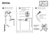
1. MOUNTING RECOMMENDATIONS:<br />
1a. Do not install the receiver against or sheltered by a<br />
metallic part as this might affect the radio transmission.<br />
1b. Minimum distance above floor: 150cm<br />
1c. Minimum distance below ceiling: 30cm<br />
1d. Minimum distance between receiver and<br />
transmitter: 30cm<br />
1e. Minimum distance between two receivers: 20cm<br />
2. OPERATION NOTICE:<br />
2a. Motor single Max running time is 5min<br />
2b. A total of 20 codes/transmitters can be stored.<br />
2c. LED1 will shine constantly when connected to main<br />
power supply except when specified under programming.<br />
2d. JP1 is a ”dry contact” or ”contact closure”<br />
2e. JP2 is a trigger signal (Power in - screen down, power<br />
off - screen up).<br />
3. TRANSMITTER & RECEIVER PROGRAMMING:<br />
3a. Press memory button, SW4. LED1 will begin flashing.<br />
3b. Press UP on selected transmitter within 10s.<br />
Transmitter is memorized and LED1 stops flashing.<br />
Programming is complete.<br />
3c. If no signal is received within the 10s the receiver<br />
goes back to normal state.<br />
3d. IR-remotes needs to be stored in the same way.<br />
4. REVERSE FUNCTION:<br />
4a. Press programming button (SW4), LED1 will start<br />
flashing.<br />
4b. Press STOP button on transmitter, LED1 will stop<br />
falshing and reverse function has been set.<br />
5. DELETE A STORED TRANSMITTER:<br />
5a. Press memory button, SW4. LED1 will begin flashing.<br />
5b. Press DOWN on selected transmitter within 10s.<br />
Transmitter is erased and LED1 stops flashing.<br />
5c. If no signal is received within the 10s the receiver<br />
goes back to normal state.<br />
UP<br />
STOP<br />
DOWN<br />
fig 18<br />
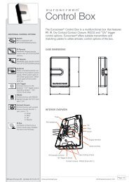
COMPONENTS:<br />
LED1<br />
IR1<br />
JP1<br />
JP2<br />
1 3<br />
2 4<br />
2 4 6<br />
IR STOP GND<br />
+5V UP DOWN<br />
1 3 5<br />
CNT1<br />
L N E<br />
220VAC IN<br />
LED1: Main Power/Signal LED<br />
E N L R<br />
Motor<br />
CNT2<br />
SW4: Transmitter programming/memory button<br />
IR1: IR-receiver eye<br />
CNT1: AC Main Power Terminal (230V)<br />
L: Phase to MAIN<br />
N: Neutral to MAIN<br />
E: Earth to MAIN<br />
CNT2: Motor Cable Terminals<br />
E: Earth to Motor<br />
N: Common to Motor<br />
L: UP/DOWN to Motor<br />
R: DOWN/UP to Motor<br />
JP1: Dry contact Switch<br />
1. (for future use)<br />
2. (for future use)<br />
3. UP: dry contact<br />
4. STOP: dry contact<br />
5. DOWN: dry contact<br />
6. GND: Common to dry contact switch<br />
JP2 - Trigge<br />
1 2<br />
NC GND +1<br />
JP1 - Ext IR &<br />
1 2 3<br />
+5V IR UP<br />
S<br />
7<br />
JP2: Trigger signal<br />
1. (empty)<br />
2. GND<br />
3. +12V<br />
4. (empty)