Linea TabTension - Draper Group Ltd
Linea TabTension - Draper Group Ltd Linea TabTension - Draper Group Ltd
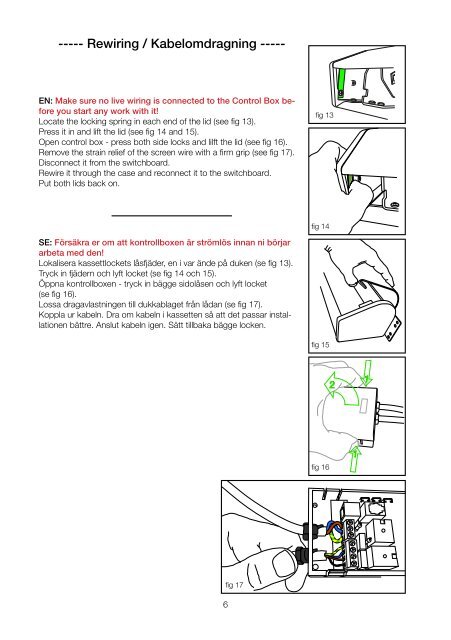
----- Rewiring / Kabelomdragning ----- EN: Make sure no live wiring is connected to the Control Box before you start any work with it! Locate the locking spring in each end of the lid (see fig 13). Press it in and lift the lid (see fig 14 and 15). Open control box - press both side locks and lilft the lid (see fig 16). Remove the strain relief of the screen wire with a firm grip (see fig 17). Disconnect it from the switchboard. Rewire it through the case and reconnect it to the switchboard. Put both lids back on. fig 13 fig 14 SE: Försäkra er om att kontrollboxen är strömlös innan ni börjar arbeta med den! Lokalisera kassettlockets låsfjäder, en i var ände på duken (se fig 13). Tryck in fjädern och lyft locket (se fig 14 och 15). Öppna kontrollboxen - tryck in bägge sidolåsen och lyft locket (se fig 16). Lossa dragavlastningen till dukkablaget från lådan (se fig 17). Koppla ur kabeln. Dra om kabeln i kassetten så att det passar installationen bättre. Anslut kabeln igen. Sätt tillbaka bägge locken. fig 15 2 1 fig 16 1 6 fig 17
Wiring & Programming / Koppling & Programmering SW4 EN: 1. MOUNTING RECOMMENDATIONS: 1a. Do not install the receiver against or sheltered by a metallic part as this might affect the radio transmission. 1b. Minimum distance above floor: 150cm 1c. Minimum distance below ceiling: 30cm 1d. Minimum distance between receiver and transmitter: 30cm 1e. Minimum distance between two receivers: 20cm 2. OPERATION NOTICE: 2a. Motor single Max running time is 5min 2b. A total of 20 codes/transmitters can be stored. 2c. LED1 will shine constantly when connected to main power supply except when specified under programming. 2d. JP1 is a ”dry contact” or ”contact closure” 2e. JP2 is a trigger signal (Power in - screen down, power off - screen up). 3. TRANSMITTER & RECEIVER PROGRAMMING: 3a. Press memory button, SW4. LED1 will begin flashing. 3b. Press UP on selected transmitter within 10s. Transmitter is memorized and LED1 stops flashing. Programming is complete. 3c. If no signal is received within the 10s the receiver goes back to normal state. 3d. IR-remotes needs to be stored in the same way. 4. REVERSE FUNCTION: 4a. Press programming button (SW4), LED1 will start flashing. 4b. Press STOP button on transmitter, LED1 will stop falshing and reverse function has been set. 5. DELETE A STORED TRANSMITTER: 5a. Press memory button, SW4. LED1 will begin flashing. 5b. Press DOWN on selected transmitter within 10s. Transmitter is erased and LED1 stops flashing. 5c. If no signal is received within the 10s the receiver goes back to normal state. UP STOP DOWN fig 18 COMPONENTS: LED1 IR1 JP1 JP2 1 3 2 4 2 4 6 IR STOP GND +5V UP DOWN 1 3 5 CNT1 L N E 220VAC IN LED1: Main Power/Signal LED E N L R Motor CNT2 SW4: Transmitter programming/memory button IR1: IR-receiver eye CNT1: AC Main Power Terminal (230V) L: Phase to MAIN N: Neutral to MAIN E: Earth to MAIN CNT2: Motor Cable Terminals E: Earth to Motor N: Common to Motor L: UP/DOWN to Motor R: DOWN/UP to Motor JP1: Dry contact Switch 1. (for future use) 2. (for future use) 3. UP: dry contact 4. STOP: dry contact 5. DOWN: dry contact 6. GND: Common to dry contact switch JP2 - Trigge 1 2 NC GND +1 JP1 - Ext IR & 1 2 3 +5V IR UP S 7 JP2: Trigger signal 1. (empty) 2. GND 3. +12V 4. (empty)
- Page 1 and 2: 13 dec 2011, 15:12 Linea TabTension
- Page 3 and 4: Limit setting / Gränslägen 1 2 3
- Page 5: Assembly / Montering ----- Width:
- Page 9 and 10: Tensioning / Trådspänning EN: To
- Page 11 and 12: Efterlevda reglement Draper Europe
----- Rewiring / Kabelomdragning -----<br />
EN: Make sure no live wiring is connected to the Control Box before<br />
you start any work with it!<br />
Locate the locking spring in each end of the lid (see fig 13).<br />
Press it in and lift the lid (see fig 14 and 15).<br />
Open control box - press both side locks and lilft the lid (see fig 16).<br />
Remove the strain relief of the screen wire with a firm grip (see fig 17).<br />
Disconnect it from the switchboard.<br />
Rewire it through the case and reconnect it to the switchboard.<br />
Put both lids back on.<br />
fig 13<br />
fig 14<br />
SE: Försäkra er om att kontrollboxen är strömlös innan ni börjar<br />
arbeta med den!<br />
Lokalisera kassettlockets låsfjäder, en i var ände på duken (se fig 13).<br />
Tryck in fjädern och lyft locket (se fig 14 och 15).<br />
Öppna kontrollboxen - tryck in bägge sidolåsen och lyft locket<br />
(se fig 16).<br />
Lossa dragavlastningen till dukkablaget från lådan (se fig 17).<br />
Koppla ur kabeln. Dra om kabeln i kassetten så att det passar installationen<br />
bättre. Anslut kabeln igen. Sätt tillbaka bägge locken.<br />
fig 15<br />
2<br />
1<br />
fig 16<br />
1<br />
6<br />
fig 17


