P-40 Warhawk 300 ARF - Stanbridges Hobby Shop
P-40 Warhawk 300 ARF - Stanbridges Hobby Shop
P-40 Warhawk 300 ARF - Stanbridges Hobby Shop

Create successful ePaper yourself
Turn your PDF publications into a flip-book with our unique Google optimized e-Paper software.
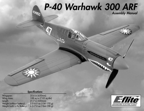
P-<strong>40</strong> <strong>Warhawk</strong> <strong>300</strong> <strong>ARF</strong><br />
Assembly Manual<br />
Specifications<br />
Wingspan:<br />
25.6 in (650mm)<br />
Wing Area:<br />
108 sq in (7.02 sq dm)<br />
Length:<br />
21.7 in (550mm)<br />
Weight (without battery): 5.5–6.0 oz (156–170 g)<br />
Weight (with Li-Po Battery): 6.5–7.0 oz (184–198 g)
Table of Contents<br />
Introduction............................................................ 2<br />
Important Warranty Information.............................. 2<br />
Using the Manual................................................... 2<br />
Product Registration................................................ 2<br />
Contents of Kit/Parts Layout.................................... 2<br />
Recommended Radio Equipment.............................. 3<br />
Additional Electronics.............................................. 3<br />
Optional Accessories.............................................. 3<br />
Required Tools and Adhesives................................. 3<br />
Note on Lithium Polymer Batteries............................ 3<br />
Electronics Installation............................................. 3<br />
Linkage Connections............................................... 6<br />
Wing Installation.................................................... 8<br />
Battery Installation.................................................. 9<br />
Spinner Installation................................................. 9<br />
Propeller Removal and Replacement....................... 10<br />
Display Stand Assembly........................................ 11<br />
Control Throws..................................................... 12<br />
Center of Gravity.................................................. 13<br />
Preflight............................................................... 13<br />
Range Test Your Radio........................................... 14<br />
Flying Your P-<strong>40</strong> <strong>Warhawk</strong>................................... 14<br />
Safety Do’s and Don’ts for Pilots............................ 14<br />
Age Requirements................................................. 14<br />
Safety, Precautions and Warnings.......................... 15<br />
Warranty Information........................................... 15<br />
CE Compliance Information for the<br />
European Union.............................................. 17<br />
2009 Official Academy of<br />
Model Aeronautics Safety Code........................ 17<br />
Declaration of Conformity..................................... 18<br />
Introduction<br />
Thank you for purchasing the E-flite ® P-<strong>40</strong> <strong>Warhawk</strong><br />
<strong>300</strong> <strong>ARF</strong>. On paper, the P-<strong>40</strong> was outclassed by many<br />
of the foes it faced. But in the hands of the pilots of the<br />
American Volunteers Group, the <strong>Warhawk</strong> was used<br />
to deadly effect against “superior” Zeros. Their exploits<br />
made the iconic shark-toothed grin of the “Flying<br />
Tigers” a symbol of victory for the Allies and cause for<br />
concern to any enemy pilot that encountered it.<br />
E-flite has captured the spirit of the Tigers in this funto-fly<br />
recreation of the P-<strong>40</strong> that goes together fast<br />
and is small enough to fly in the park. It comes out<br />
of the box loaded with scale details like an authentic<br />
Flying Tigers paint scheme and molded panel lines. It<br />
also comes equipped with a factory-installed <strong>300</strong> BL<br />
outrunner motor that will provide plenty of power for<br />
warbird aerobatics like loops, rolls and Immelmans. Its<br />
simple 3-channel control setup means you only need to<br />
buy two servos – one for aileron and one for elevator<br />
– making it even more affordable to get flying. When<br />
you’re not flying, you can show off its scale looks with<br />
included static display stand.<br />
Important Warranty Information<br />
Please read our Warranty and Liability Limitations<br />
section on Page 14 before building this product. If you<br />
as the Purchaser or user are not prepared to accept the<br />
liability associated with the use of this Product, you are<br />
advised to return this Product immediately in new and<br />
unused condition to the place of purchase.<br />
Using the Manual<br />
This manual is divided into sections to help make<br />
assembly easier to understand, and to provide breaks<br />
between each major section. In addition, check boxes<br />
have been placed next to each step to keep track of its<br />
completion.<br />
Remember to take your time and follow the directions.<br />
Product Registration<br />
Register your product online at:<br />
www.e-fliterc.com/register/<br />
Contents of Kit/Parts Layout<br />
EFL6076<br />
Fuselage with Tail and Hatch<br />
EFL6077<br />
Main Wing<br />
EFL6078 Propeller (2)<br />
EFL6079<br />
Spinner<br />
EFL6080<br />
Motor<br />
EFL6081<br />
Canopy Hatch<br />
EFL6082 Wing Mount O-rings (3)<br />
EFL6083<br />
Horizontal Stabilizer<br />
2 E-flite P-<strong>40</strong> <strong>Warhawk</strong> Assembly Manual
Recommended Radio Equipment<br />
You will need a minimum 4-channel transmitter,<br />
receiver, and two servos. You can also choose to<br />
purchase a complete radio system. If you are using an<br />
existing transmitter, just purchase the other required<br />
equipment separately. We recommend the crystalfree,<br />
interference-free Spektrum DX5e 2.4GHz DSM ®<br />
5-channel system.<br />
If you own the Spektrum DX5e radio, just add the<br />
AR6100e DSM2 6-channel receiver and two E-flite<br />
S60 Super Sub-Micro Servos.<br />
Transmitter and Receiver<br />
SPMAR5500 DX5e 5-Channel Transmitter only,<br />
Mode 2<br />
Purchase Separately<br />
SPMAR6100E AR6100E 6-Channel Receiver, Air<br />
And<br />
EFLRS60 S60 Super Sub Micro Servo (2)<br />
EFLB4302SJ<br />
EFLA1010<br />
Additional Electronics<br />
430mAh 2S 7.4V 20C LiPo,<br />
20AWG JST<br />
10-Amp Pro Brushless ESC<br />
EFLA110<br />
EFLC<strong>300</strong>5<br />
EFLC505<br />
Optional Accessories<br />
Power Meter<br />
Celectra 1–3 Cell<br />
Li-Po Charger<br />
Intelligent 1- to 5-Cell<br />
Balancing Charger<br />
Required Tools and Adhesives<br />
Tools & Equipment<br />
<strong>Hobby</strong> knife with #11 blade<br />
Phillips screwdriver: #0<br />
Flat blade screwdriver<br />
Nut driver: 5mm<br />
Two-sided tape<br />
Ruler<br />
Adhesives<br />
Foam CA 1oz/Activator 2 oz Pack (EFLA208)<br />
Canopy Glue (PAAPT56)<br />
Note on Lithium Polymer Batteries<br />
Lithium Polymer batteries are significantly<br />
more volatile than alkaline or Ni-Cd/<br />
Ni-MH batteries used in RC applications.<br />
All manufacturer’s instructions and warnings<br />
must be followed closely. Mishandling of<br />
Li-Po batteries can result in fire. Always<br />
follow the manufacturer’s instructions when<br />
disposing of Lithium Polymer batteries.<br />
<br />
Required Parts<br />
Fuselage assembly<br />
Servo with horn (2)<br />
Speed control<br />
Transmitter<br />
Electronics Installation<br />
Wing assembly<br />
Receiver<br />
Flight battery<br />
Required Tools<br />
Foam-safe CA <strong>Hobby</strong> knife with #11 blade<br />
Two-sided tape Phillips screwdriver: #0<br />
If you are using a computer radio, it is recommended<br />
to start with a new program and clear it before<br />
starting the installation of the electronics. Make sure<br />
the trims, sub-trims and sticks are centered, and no<br />
programmable mixing has been turned on as well.<br />
1. Use a #0 Phillips screwdriver to remove the<br />
servo horns from the two servos.<br />
During the course of building your model we suggest<br />
that you use a soft base for the building surface.<br />
Such things as a foam stand, large piece of bedding<br />
foam or a thick bath towel will work well and help<br />
protect the model from damage during assembly.<br />
The Spektrum trademark is used with permission<br />
of Bachmann Industries, Inc.<br />
E-flite P-<strong>40</strong> <strong>Warhawk</strong> Assembly Manual<br />
3
2. Use a hobby knife with a #11 blade to cut a<br />
narrow notch at the edge of the servo pocket in the<br />
wing to allow the servo wire from the aileron servo<br />
to fit in.<br />
<br />
3. Press the servo into the servo pocket in the<br />
wing. Make sure to guide the servo wire into the<br />
notch made in the previous step. Note that the<br />
output of the servo faces to the trailing edge (rear)<br />
of the wing.<br />
<br />
5. Use a hobby knife with a #11 blade to cut a<br />
narrow notch at the edge of the servo pocket in the<br />
fuselage for the elevator servo to allow the servo<br />
wire to fit in.<br />
<br />
4. Place a drop or two of foam-safe CA in the hole<br />
in the servo tab. The CA will go through the hole<br />
and bond the servo to the wing.<br />
<br />
6. Press the servo into the servo pocket in the<br />
fuselage. Make sure to guide the servo wire into<br />
the notch made in the previous step. Note that<br />
the output of the servo faces to the front of the<br />
fuselage. Place a drop or two of foam-safe CA in<br />
the hole in the servo tab. The CA will go through<br />
the hole and bond the servo to the fuselage.<br />
4 E-flite P-<strong>40</strong> <strong>Warhawk</strong> Assembly Manual
7. Plug the speed control and elevator servo<br />
connectors into the receiver.<br />
<br />
9. Connect the leads from the motor to the<br />
speed control.<br />
<br />
11. Check the operation of your motor at this<br />
time using the radio system. The motor should<br />
spin counterclockwise when viewed from the front<br />
of the fuselage. If not, follow the speed control<br />
manufacturer’s recommendations to reverse the<br />
direction if necessary. Once the direction of<br />
rotation is verified, you can install the propeller<br />
back on the motor.<br />
<br />
12. Tuck the motor leads in the fuselage as shown.<br />
<br />
8. Place a small piece of two-sided tape on the<br />
receiver. Slide the receiver into the fuselage and<br />
press it against the tape to secure it into the<br />
fuselage. Make sure to leave enough of the receiver<br />
exposed to know which port to plug the aileron<br />
servo into.<br />
<br />
10. Use two-sided tape to secure the speed control<br />
in the fuselage as shown.<br />
<br />
13. Insert the lead for the battery from the speed<br />
control into the larger hole in the fuselage. The lead<br />
will enter the compartment under the canopy.<br />
Before checking the rotation of your motor,<br />
make sure to remove the propeller to avoid any<br />
accidental injuries. The details for removing<br />
the propeller can be found on Page 10,<br />
“Propeller Removal and Installation.”<br />
E-flite P-<strong>40</strong> <strong>Warhawk</strong> Assembly Manual<br />
5
Linkage Connections<br />
Required Parts<br />
Fuselage assembly Wing assembly<br />
Flight battery Transmitter<br />
Single-sided servo horn<br />
Double-sided servo horn<br />
Required Tools<br />
Ruler<br />
Flat blade screwdriver<br />
Phillips screwdriver: #0<br />
<strong>Hobby</strong> knife with #11 blade<br />
<br />
2. Use a hobby knife to enlarge the hole in a<br />
single-sided servo horn that is 9/32-inch (7mm)<br />
from the center of the servo horn. The hole needs<br />
to be big enough to insert the pushrod wire for the<br />
elevator. Use care not to make the hole too large as<br />
this will cause slop in the control system.<br />
<br />
4. Use the radio system to center the elevator<br />
servo. Secure the servo horn to the elevator servo<br />
using the screw removed in the previous section of<br />
the manual. You will need a #0 Phillips screwdriver<br />
to tighten the screw.<br />
<br />
1. Inspect the clevis and its connection to the elevator<br />
control horn. Note which hole the clevis is attached<br />
to. Use a flat blade screwdriver to open the clevis<br />
and remove it from the elevator control horn.<br />
<br />
3. Insert the pushrod wire from the elevator into the<br />
hole enlarged in the previous step.<br />
<br />
5. Reconnect the clevis to the elevator control horn<br />
in the hole noted in Step 1. Make sure the clevis<br />
is secure before proceeding. Check to see that the<br />
elevator is level when the servo is centered. If not<br />
adjust the clevis to the correct length by adjusting<br />
the clevis in or out on the pushrod.<br />
6 E-flite P-<strong>40</strong> <strong>Warhawk</strong> Assembly Manual
6. Use a hobby knife to enlarge the holes in a<br />
double-sided servo horn that is 1/2-inch (13mm)<br />
from the center of the servo horn. The hole needs<br />
to be big enough to insert the pushrod wires for the<br />
ailerons. Use care not to make the hole too large<br />
as this will cause slop in the control system.<br />
<br />
7. Install the servo horn on the aileron linkages by<br />
inserting both linkages into the holes in the servo<br />
arm. The arm is then rotated on the bends so the<br />
splines face to the aileron servo.<br />
<br />
8. Use the radio system to center the aileron servo.<br />
Secure the servo horn to the aileron servo using<br />
the screw removed in the previous section of the<br />
manual. You will need a #0 Phillips screwdriver to<br />
tighten the screw.<br />
<br />
9. Check to make sure the aileron is aligned with<br />
the trailing edge of the wing. If not, thread the<br />
clevis in or out until the two are aligned. Make sure<br />
to check both the left and right ailerons.<br />
E-flite P-<strong>40</strong> <strong>Warhawk</strong> Assembly Manual<br />
7
Wing Installation<br />
Required Parts<br />
Fuselage assembly Wing assembly<br />
O-ring tool<br />
<br />
3. Position the wing on the bottom of the fuselage.<br />
The pins at the front of the wing will slide into the<br />
holes in the fuselage.<br />
<br />
5. Use the O-ring tool to pull the O-ring upward<br />
so it can be hooked onto the tab at the rear of the<br />
cockpit as shown.<br />
Before installing the wing stretch the O-ring slightly<br />
by holding the base of the mount in the wing and<br />
pulling tension on the O-ring. Do not use much<br />
force as you could damage the wing or the mount.<br />
Repeat this process 2 or 3 times. This will allow<br />
the O-ring to stretch some before it is installed.<br />
<br />
1. Remove the canopy from the fuselage by lifting it<br />
upward. The canopy is held on with magnets.<br />
<br />
4. Press the rear of the wing down so the wing fits<br />
tight against the fuselage. Make sure none of the<br />
wires from the inside of the fuselage are exposed<br />
on the top side of the wing.<br />
<br />
2. Plug the aileron servo into the receiver.<br />
8 E-flite P-<strong>40</strong> <strong>Warhawk</strong> Assembly Manual
Battery Installation<br />
<br />
3. Place the canopy back on the fuselage.<br />
Spinner Installation<br />
<br />
Required Parts<br />
Assembled airframe<br />
Motor battery<br />
1. Slide the motor battery into the fuselage. It<br />
should slide in easily with little force.<br />
Required Parts<br />
Fuselage assembly<br />
Required Tools<br />
Nut driver: 5mm<br />
Spinner<br />
Canopy glue<br />
Please note that your spinner is not<br />
glued on from the factory. It is just slid<br />
on to the prop and needs to be removed<br />
and glued on for saftey.<br />
<br />
1. Apply a small amount of canopy glue to the nut.<br />
Use a small amount so the spinner can be easily<br />
removed if the propeller requires replacement.<br />
Make sure that the leads are tucked into the hole in the<br />
fuselage so that the canopy fits correctly on the model.<br />
If not you could loose your canopy during flight.<br />
<br />
2. When you are ready to fly your aircraft, connect<br />
the lead from the battery to the lead from the speed<br />
control. Tuck the leads into the hole or alongside<br />
the battery so the canopy can be installed.<br />
<br />
2. Slide the spinner back on the propeller. Allow<br />
the glue to fully cure before flying your model.<br />
E-flite P-<strong>40</strong> <strong>Warhawk</strong> Assembly Manual<br />
9
Propeller and Spinner<br />
Removal and Replacement<br />
Required Parts<br />
Fuselage assembly<br />
Spinner<br />
Required Tools<br />
Nut driver: 5mm<br />
Propeller<br />
Canopy glue<br />
<br />
2. Use a 5mm nut driver to remove the nut holding<br />
the propeller on the motor.<br />
<br />
4. Before installing a new propeller, make sure it is<br />
installed in the correct direction. One side will have<br />
a hex that keys to the motor. Make sure it installed<br />
with this hex toward the motor.<br />
<br />
1. Carefully pull the spinner forward to remove it<br />
from the motor. It will take a small amount of force<br />
to remove.<br />
<br />
3. Remove the washer and propeller from the motor.<br />
<br />
5. Slide the propeller on the motor shaft.<br />
If you are checking the rotation of the motor, now is<br />
the time to do so while the propeller is removed.<br />
10 E-flite P-<strong>40</strong> <strong>Warhawk</strong> Assembly Manual
6. Next, slide the washer back on the motor shaft.<br />
Thread the 5mm locknut back on the shaft.<br />
<br />
8. Apply a small amount of canopy glue to the nut.<br />
Use a small amount so the spinner can be easily<br />
removed if the propeller requires replacement.<br />
Display Stand Assembly<br />
Required Parts<br />
Assembled airframe Display stand base<br />
Display stand strut<br />
<br />
1. Insert the tab from the display stand strut into the<br />
slot in the display stand base. They will fit tight and<br />
not require glue to keep them from coming apart.<br />
<br />
7. Use a 5mm nut driver to tighten the nut holding<br />
the propeller on the motor.<br />
<br />
9. Slide the spinner back on the propeller. Allow<br />
the glue to fully cure before flying your model.<br />
E-flite P-<strong>40</strong> <strong>Warhawk</strong> Assembly Manual<br />
11
2. The mount for the plane can swivel on the<br />
display stand strut. This allows you to position your<br />
model for the best dramatic effect while on display.<br />
<br />
3. The plane will rest on the mount. The straight pin<br />
on the mount is inserted into the hole in the area of<br />
the finger grips as shown.<br />
<br />
Control Throws<br />
1. Turn on the transmitter and receiver of<br />
your model.<br />
<br />
2. Check the movement of the elevator with the<br />
radio system. Moving the elevator stick toward the<br />
bottom of the transmitter will make the airplane<br />
elevator move up.<br />
<br />
3. Check the movement of the ailerons with the<br />
radio system. Moving the aileron stick right will<br />
make the right aileron move up and the left aileron<br />
move down.<br />
<br />
4. With the stand and plane upright, you are now<br />
able to display your model when you are not out<br />
flying sorties.<br />
<br />
4. Use a ruler to adjust the throw of the elevator<br />
and ailerons.<br />
12 E-flite P-<strong>40</strong> <strong>Warhawk</strong> Assembly Manual
Range Test Your Radio<br />
Flying Your P-<strong>40</strong> <strong>Warhawk</strong><br />
Age Requirements<br />
<br />
1. Before each flying session, be sure to range<br />
check your radio. See your radio manual for the<br />
recommended range and instructions for your<br />
radio system. Each radio manufacturer specifies<br />
different procedures for their radio systems. Next,<br />
start the motor. With the model securely anchored,<br />
check the range again. The range test should not<br />
be significantly affected. If it is, don’t attempt to<br />
fly! Have your radio equipment checked out by the<br />
manufacturer.<br />
Flying the P-<strong>40</strong> <strong>Warhawk</strong> is a pleasure you will not<br />
soon forget. A gentle hand launch with full throttle is<br />
all that is needed to get the P-<strong>40</strong> into the air. Once you<br />
are airborne, you will find that the P-<strong>40</strong> is very smooth<br />
and handles very well. Basic aerobatics such as loops<br />
and rolls are a breeze with the P-<strong>40</strong>. Both high and<br />
low speed flight are also easily obtained. When it is<br />
time to land, a gentle descent while carrying a little<br />
power is all that is needed. Once you are over the<br />
threshold and about one foot off the ground, pull the<br />
power off and gently apply up elevator to flair for a<br />
smooth landing.<br />
Age Recommendation: 14 years or over. This is not<br />
a toy. This product is not intended for use by children<br />
without direct adult supervision.<br />
<br />
<br />
2. Double-check that all controls (aileron, elevator<br />
and throttle) move in the correct direction.<br />
3. Be sure that your transmitter batteries are<br />
fully charged, per the instructions included with<br />
your radio.<br />
Happy Landings!<br />
Safety Do’s and Don’ts for Pilots<br />
• Check all control surfaces prior to each takeoff.<br />
• Do not fly your model near spectators, parking<br />
areas or any other area that could result in injury to<br />
people or damage of property.<br />
• Do not fly during adverse weather conditions. Poor<br />
visibility can cause disorientation and loss of control<br />
of your aircraft. Strong winds can cause similar<br />
problems.<br />
• Do not take chances. If at any time during flight you<br />
observe any erratic or abnormal operation, land<br />
immediately and do not resume flight until the cause<br />
of the problem has been ascertained and corrected.<br />
Safety can never be taken lightly.<br />
• Do not fly near power lines.<br />
14 E-flite P-<strong>40</strong> <strong>Warhawk</strong> Assembly Manual
Safety, Precautions and Warnings<br />
As the user of this product, you are solely responsible<br />
for operating it in a manner that does not endanger<br />
yourself and others or result in damage to the product<br />
or the property of others.<br />
Carefully follow the directions and warnings for<br />
this and any optional support equipment (chargers,<br />
rechargeable battery packs, etc.) that you use.<br />
This model is controlled by a radio signal that is<br />
subject to interference from many sources outside<br />
your control. This interference can cause momentary<br />
loss of control so it is necessary to always keep a safe<br />
distance in all directions around your model, as this<br />
margin will help to avoid collisions or injury.<br />
• Always operate your model in an open area away<br />
from cars, traffic or people.<br />
• Avoid operating your model in the street where<br />
injury or damage can occur.<br />
• Never operate the model out into the street or<br />
populated areas for any reason.<br />
• Never operate your model with low transmitter<br />
batteries.<br />
• Carefully follow the directions and warnings for<br />
this and any optional support equipment (chargers,<br />
rechargeable battery packs, etc.) that you use.<br />
• Keep all chemicals, small parts and anything<br />
electrical out of the reach of children.<br />
• Moisture causes damage to electronics. Avoid water<br />
exposure to all equipment not specifically designed<br />
and protected for this purpose.<br />
Warranty Period<br />
Warranty Information<br />
Exclusive Warranty- Horizon <strong>Hobby</strong>, Inc., (Horizon)<br />
warranties that the Products purchased (the “Product”)<br />
will be free from defects in materials and workmanship<br />
at the date of purchase by the Purchaser.<br />
Limited Warranty<br />
(a) This warranty is limited to the original Purchaser<br />
(“Purchaser”) and is not transferable. REPAIR<br />
OR REPLACEMENT AS PROVIDED UNDER THIS<br />
WARRANTY IS THE EXCLUSIVE REMEDY OF THE<br />
PURCHASER. This warranty covers only those Products<br />
purchased from an authorized Horizon dealer. Third<br />
party transactions are not covered by this warranty.<br />
Proof of purchase is required for warranty claims.<br />
Further, Horizon reserves the right to change or modify<br />
this warranty without notice and disclaims all other<br />
warranties, express or implied.<br />
(b) Limitations- HORIZON MAKES NO WARRANTY<br />
OR REPRESENTATION, EXPRESS OR IMPLIED,<br />
ABOUT NON-INFRINGEMENT, MERCHANTABILITY<br />
OR FITNESS FOR A PARTICULAR PURPOSE OF THE<br />
PRODUCT. THE PURCHASER ACKNOWLEDGES<br />
THAT THEY ALONE HAVE DETERMINED THAT THE<br />
PRODUCT WILL SUITABLY MEET THE REQUIREMENTS<br />
OF THE PURCHASER’S INTENDED USE.<br />
(c) Purchaser Remedy- Horizon’s sole obligation<br />
hereunder shall be that Horizon will, at its option,<br />
(i) repair or (ii) replace, any Product determined<br />
by Horizon to be defective. In the event of a defect,<br />
these are the Purchaser’s exclusive remedies. Horizon<br />
reserves the right to inspect any and all equipment<br />
involved in a warranty claim. Repair or replacement<br />
decisions are at the sole discretion of Horizon.<br />
This warranty does not cover cosmetic damage or<br />
damage due to acts of God, accident, misuse, abuse,<br />
negligence, commercial use, or modification of or<br />
to any part of the Product. This warranty does not<br />
cover damage due to improper installation, operation,<br />
maintenance, or attempted repair by anyone other<br />
than Horizon. Return of any goods by Purchaser must<br />
be approved in writing by Horizon before shipment.<br />
Damage Limits<br />
HORIZON SHALL NOT BE LIABLE FOR SPECIAL,<br />
INDIRECT OR CONSEQUENTIAL DAMAGES, LOSS<br />
OF PROFITS OR PRODUCTION OR COMMERCIAL<br />
LOSS IN ANY WAY CONNECTED WITH THE<br />
PRODUCT, WHETHER SUCH CLAIM IS BASED IN<br />
CONTRACT, WARRANTY, NEGLIGENCE, OR STRICT<br />
LIABILITY. Further, in no event shall the liability of<br />
Horizon exceed the individual price of the Product on<br />
which liability is asserted. As Horizon has no control<br />
over use, setup, final assembly, modification or misuse,<br />
no liability shall be assumed nor accepted for any<br />
resulting damage or injury. By the act of use, setup or<br />
assembly, the user accepts all resulting liability.<br />
If you as the Purchaser or user are not prepared<br />
to accept the liability associated with the use of<br />
this Product, you are advised to return this Product<br />
immediately in new and unused condition to the place<br />
of purchase.<br />
Law: These Terms are governed by Illinois law (without<br />
regard to conflict of law principals).<br />
Safety Precautions<br />
This is a sophisticated hobby Product and not a toy.<br />
It must be operated with caution and common sense<br />
and requires some basic mechanical ability. Failure to<br />
operate this Product in a safe and responsible manner<br />
could result in injury or damage to the Product or<br />
other property. This Product is not intended for use by<br />
children without direct adult supervision. The Product<br />
manual contains instructions for safety, operation and<br />
maintenance. It is essential to read and follow all<br />
the instructions and warnings in the manual, prior to<br />
assembly, setup or use, in order to operate correctly<br />
and avoid damage or injury.<br />
E-flite P-<strong>40</strong> <strong>Warhawk</strong> Assembly Manual<br />
15
Questions, Assistance, and Repairs<br />
Your local hobby store and/or place of purchase<br />
cannot provide warranty support or repair. Once<br />
assembly, setup or use of the Product has been<br />
started, you must contact Horizon directly. This will<br />
enable Horizon to better answer your questions<br />
and service you in the event that you may need any<br />
assistance. For questions or assistance, please direct<br />
your email to productsupport@horizonhobby.com,<br />
or call 877.504.0233 toll free to speak to a service<br />
technician.<br />
Inspection or Repairs<br />
If this Product needs to be inspected or repaired,<br />
please call for a Return Merchandise Authorization<br />
(RMA). Pack the Product securely using a shipping<br />
carton. Please note that original boxes may be<br />
included, but are not designed to withstand the rigors<br />
of shipping without additional protection. Ship via a<br />
carrier that provides tracking and insurance for lost<br />
or damaged parcels, as Horizon is not responsible<br />
for merchandise until it arrives and is accepted at our<br />
facility. A Service Repair Request is available at www.<br />
horizonhobby.com on the “Support” tab. If you do<br />
not have internet access, please include a letter with<br />
your complete name, street address, email address<br />
and phone number where you can be reached during<br />
business days, your RMA number, a list of the included<br />
items, method of payment for any non-warranty<br />
expenses and a brief summary of the problem.<br />
Your original sales receipt must also be included for<br />
warranty consideration. Be sure your name, address,<br />
and RMA number are clearly written on the outside of<br />
the shipping carton.<br />
Warranty Inspection and Repairs<br />
To receive warranty service, you must include your<br />
original sales receipt verifying the proof-of-purchase<br />
date. Provided warranty conditions have been met,<br />
your Product will be repaired or replaced free of<br />
charge. Repair or replacement decisions are at the sole<br />
discretion of Horizon <strong>Hobby</strong>.<br />
Non-Warranty Repairs<br />
Should your repair not be covered by warranty the<br />
repair will be completed and payment will be required<br />
without notification or estimate of the expense unless<br />
the expense exceeds 50% of the retail purchase cost.<br />
By submitting the item for repair you are agreeing<br />
to payment of the repair without notification. Repair<br />
estimates are available upon request. You must include<br />
this request with your repair. Non-warranty repair<br />
estimates will be billed a minimum of 1/2 hour of<br />
labor. In addition you will be billed for return freight.<br />
Please advise us of your preferred method of payment.<br />
Horizon accepts money orders and cashiers checks,<br />
as well as Visa, MasterCard, American Express, and<br />
Discover cards. If you choose to pay by credit card,<br />
please include your credit card number and expiration<br />
date. Any repair left unpaid or unclaimed after 90<br />
days will be considered abandoned and will be<br />
disposed of accordingly. Please note: non-warranty<br />
repair is only available on electronics and model<br />
engines.<br />
United States:<br />
Electronics and engines requiring inspection or repair<br />
should be shipped to the following address:<br />
Horizon Service Center<br />
4105 Fieldstone Road<br />
Champaign, Illinois 61822<br />
All other Products requiring warranty inspection or<br />
repair should be shipped to the following address:<br />
Horizon Product Support<br />
4105 Fieldstone Road<br />
Champaign, Illinois 61822<br />
Please call 877-504-0233 or e-mail us at<br />
productsupport@horizonhobby.com with any questions<br />
or concerns regarding this product or warranty.<br />
United Kingdom:<br />
Electronics and engines requiring inspection or repair<br />
should be shipped to the following address:<br />
Horizon <strong>Hobby</strong> UK<br />
Units 1-4 Ployters Rd<br />
Staple Tye<br />
Harlow, Essex<br />
CM18 7NS<br />
United Kingdom<br />
Please call +44 (0) 1279 641 097 or e-mail us at<br />
sales@horizonhobby.co.uk with any questions or<br />
concerns regarding this product or warranty.<br />
Germany:<br />
Electronics and engines requiring inspection or repair<br />
should be shipped to the following address:<br />
Horizon Technischer Service<br />
Hamburger Strasse 10<br />
25335 Elmshorn<br />
Germany<br />
Please call +49 4121 46199 66 or e-mail us at<br />
service@horizonhobby.de with any questions or<br />
concerns regarding this product or warranty<br />
16 E-flite P-<strong>40</strong> <strong>Warhawk</strong> Assembly Manual
CE Compliance Information for the<br />
European Union<br />
Instructions for Disposal of WEEE by Users in<br />
the European Union<br />
This product must not be disposed of with other waste.<br />
Instead, it is the user’s responsibility to dispose of their<br />
waste equipment by handing it over to a designated<br />
collection point for the recycling of waste electrical<br />
and electronic equipment. The separate collection<br />
and recycling of your waste equipment at the time<br />
of disposal will help to conserve natural resources<br />
and ensure that it is recycled in a manner that<br />
protects human health and the environment. For more<br />
information about where you can drop off your waste<br />
equipment for recycling, please contact your local city<br />
office, your household waste disposal service or where<br />
you purchased the product.<br />
2009 Official Academy of Model<br />
Aeronautics Safety Code<br />
GENERAL<br />
1. A model aircraft shall be defined as a nonhuman-carrying<br />
device capable of sustained<br />
flight in the atmosphere. It shall not exceed<br />
limitations established in this code and is<br />
intended to be used exclusively for recreational<br />
or competition activity.<br />
2. The maximum takeoff weight of a model aircraft,<br />
including fuel, is 55 pounds, except for those<br />
flown under the AMA Experimental Aircraft<br />
Rules.<br />
3. I will abide by this Safety Code and all rules<br />
established for the flying site I use. I will not<br />
willfully fly my model aircraft in a reckless and/<br />
or dangerous manner.<br />
4. I will not fly my model aircraft in sanctioned<br />
events, air shows, or model demonstrations until<br />
it has been proven airworthy.<br />
5. I will not fly my model aircraft higher than<br />
approximately <strong>40</strong>0 feet above ground level,<br />
when within three (3) miles of an airport without<br />
notifying the airport operator. I will yield the<br />
right-of-way and avoid flying in the proximity<br />
of full-scale aircraft, utilizing a spotter when<br />
appropriate.<br />
6. I will not fly my model aircraft unless it is<br />
identified with my name and address, or AMA<br />
number, inside or affixed to the outside of the<br />
model aircraft. This does not apply to model<br />
aircraft flown indoors.<br />
7. I will not operate model aircraft with metal-blade<br />
propellers or with gaseous boosts (other than<br />
air), nor will I operate model aircraft with fuels<br />
containing tetranitromethane or hydrazine.<br />
8. I will not operate model aircraft carrying<br />
pyrotechnic devices which explode, burn, or<br />
propel a projectile of any kind. Exceptions<br />
include Free Flight fuses or devices that burn<br />
producing smoke and are securely attached to<br />
the model aircraft during flight. Rocket motors<br />
up to a G-series size may be used, provided<br />
they remain firmly attached to the model aircraft<br />
during flight. Model rockets may be flown in<br />
accordance with the National Model Rocketry<br />
Safety Code; however, they may not be launched<br />
from model aircraft. Officially designated AMA<br />
Air Show Teams (AST) are authorized to use<br />
devices and practices as defined within the Air<br />
Show Advisory Committee Document.<br />
9. I will not operate my model aircraft while under<br />
the influence of alcohol or within eight (8) hours<br />
of having consumed alcohol.<br />
10. I will not operate my model aircraft while using<br />
any drug which could adversely affect my ability<br />
to safely control my model aircraft.<br />
11. Children under six (6) years old are only allowed<br />
on a flightline or in a flight area as a pilot or<br />
while under flight instruction.<br />
12. When and where required by rule, helmets<br />
must be properly worn and fastened. They must<br />
be OSHA, DOT, ANSI, SNELL or NOCSAE<br />
approved or comply with comparable standards.<br />
RADIO CONTROL<br />
1. All model flying shall be conducted in a manner<br />
to avoid flying over unprotected people.<br />
2. I will have completed a successful radio<br />
equipment ground-range check before the first<br />
flight of a new or repaired model aircraft.<br />
3. I will not fly my model aircraft in the presence of<br />
spectators until I become a proficient flier, unless I<br />
am assisted by an experienced pilot.<br />
E-flite P-<strong>40</strong> <strong>Warhawk</strong> Assembly Manual<br />
17
4. At all flying sites a line must be established,<br />
in front of which all flying takes place. Only<br />
personnel associated with flying the model<br />
aircraft are allowed at or in front of the line. In<br />
the case of airshows demonstrations straight line<br />
must be established. An area away from the line<br />
must be maintained for spectators. Intentional<br />
flying behind the line is prohibited.<br />
5. I will operate my model aircraft using only<br />
radio-control frequencies currently allowed by<br />
the Federal Communications Commission (FCC).<br />
Only individuals properly licensed by the FCC<br />
are authorized to operate equipment on Amateur<br />
Band frequencies.<br />
6. I will not knowingly operate my model aircraft<br />
within three (3) miles of any preexisting flying<br />
site without a frequency-management agreement.<br />
A frequency management agreement may be<br />
an allocation of frequencies for each site, a<br />
day-use agreement between sites, or testing<br />
which determines that no interference exists.<br />
A frequency-management agreement may<br />
exist between two or more AMA chartered<br />
clubs, AMA clubs and individual AMA<br />
members, or individual AMA members.<br />
Frequency-management agreements, including<br />
an interference test report if the agreement<br />
indicates no interference exists, will be signed<br />
by all parties and copies provided to AMA<br />
Headquarters.<br />
7. With the exception of events flown under official<br />
AMA rules, no powered model may be flown<br />
outdoors closer than 25 feet to any individual,<br />
except for the pilot and located at the flightline.<br />
8. Under no circumstances may a pilot or other<br />
person touch a model aircraft in flight while it is<br />
still under power, except to divert it from striking<br />
an individual.<br />
9. Radio-controlled night flying is limited to lowperformance<br />
model aircraft (less than 100 mph).<br />
The model aircraft must be equipped with a<br />
lighting system which clearly defines the aircraft’s<br />
attitude and direction at all times.<br />
10. The operator of a radio-controlled model<br />
aircraft shall control it during the entire flight,<br />
maintaining visual contact without enhancement<br />
other than by corrective lenses that are<br />
prescribed for the pilot. No model aircraft shall<br />
be equipped with devices which allow it to be<br />
flown to a selected location which is beyond the<br />
visual range of the pilot.<br />
P-<strong>40</strong> <strong>Warhawk</strong> Safe Operating Recommendations<br />
- Inspect your model before every flight to make<br />
certain it is airworthy.<br />
- Be aware of any other radio frequency user who<br />
may present an interference problem.<br />
- Always be courteous and respectful of other<br />
users of your selected flight area.<br />
- Choose an area clear of obstacles and large<br />
enough to safely accommodate your flying<br />
activity.<br />
- Make certain this area is clear of friends and<br />
spectators prior to launching your aircraft.<br />
- Be aware of other activities in the vicinity of your<br />
flight path that could cause potential conflict.<br />
- Carefully plan your flight path prior to launch.<br />
- Abide by any and all established AMA National<br />
Model Aircraft Safety Code.<br />
Declaration of Conformity<br />
(in accordance with ISO/IEC 17050-1)<br />
No. HH20090501<br />
Product(s):<br />
Item Number(s):<br />
Equipment class: 1<br />
P-<strong>40</strong> <strong>Warhawk</strong> <strong>300</strong> <strong>ARF</strong><br />
EFL6075<br />
The object of declaration described above is in<br />
conformity with the requirements of the specifications<br />
listed below, following the provisions of the European<br />
R&TTE directive 1999/5/EC:<br />
EN 301 489-1 v.1.6.1 General EMC requirements<br />
EN 301 489-17 v.1.2.1<br />
Signed for and on behalf of:<br />
Horizon <strong>Hobby</strong>, Inc.<br />
Champaign, IL USA<br />
May 1, 2009<br />
Steven A. Hall<br />
Vice President<br />
International Operations and Risk Management<br />
Horizon <strong>Hobby</strong>, Inc.<br />
18 E-flite P-<strong>40</strong> <strong>Warhawk</strong> Assembly Manual
E-flite P-<strong>40</strong> <strong>Warhawk</strong> Assembly Manual<br />
19
© 2009 Horizon <strong>Hobby</strong>, Inc.<br />
4105 Fieldstone Road<br />
Champaign, Illinois 61822<br />
U.S.A.<br />
(877) 504-0233<br />
horizonhobby.com<br />
E-fliteRC.com<br />
Printed 04/09 15659