E-flite PT-17 Stearman manual - Great Hobbies
E-flite PT-17 Stearman manual - Great Hobbies
E-flite PT-17 Stearman manual - Great Hobbies

You also want an ePaper? Increase the reach of your titles
YUMPU automatically turns print PDFs into web optimized ePapers that Google loves.
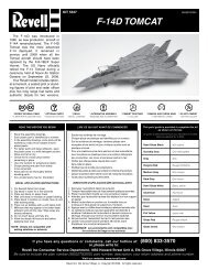
<strong>Stearman</strong> <strong>PT</strong>-<strong>17</strong> 15e ARF<br />
Assembly Manual<br />
Wingspan<br />
Length<br />
Wing Area<br />
Weight with Battery<br />
Weight without Battery<br />
Specifications<br />
44 in (11<strong>17</strong>mm)<br />
35 in (889mm)<br />
608 sq in (37.5 sq dm)<br />
3.5–3.8 lb (1.5–1.7 kg)<br />
3.1–3.3 lb (1.4–1.5 kg)<br />
Pilots not included (available separately)
Table of Contents<br />
Product Registration......................................................2<br />
Introduction ...............................................................2<br />
Warranty Information................................................. 2<br />
Using the Manual...................................................... 2<br />
Contents of Kit/Parts Layout........................................ 2<br />
Recommended Radio Equipment...................................3<br />
Recommended Equipment.............................................3<br />
Optional Accessories....................................................3<br />
Required Tools and Adhesives.......................................3<br />
Warning.....................................................................3<br />
Note on Lithium Polymer Batteries..................................3<br />
Rudder and Elevator Servo Installation............................4<br />
Stabilizer and Fin Installation.........................................5<br />
Rudder and Elevator Pushrod Installation........................8<br />
Landing Gear Installation............................................11<br />
Cabane Strut and Center Section Installation.................11<br />
Aileron Installation.....................................................15<br />
Aileron Linkage Installation.........................................16<br />
Motor and ESC Installation..........................................<strong>17</strong><br />
Cowling Installation....................................................18<br />
Interplane and Wing Transport Jig Installation...............19<br />
Battery Installation......................................................22<br />
Receiver Installation....................................................23<br />
Wing Installation........................................................24<br />
Center of Gravity........................................................25<br />
Control Throws...........................................................26<br />
Preflight.....................................................................26<br />
Safety, Precautions and Warnings...............................27<br />
Age Requirements......................................................27<br />
Safety Do’s and Don’ts for Pilots...................................27<br />
Warranty Information.................................................28<br />
2009 Official Academy of Model<br />
Aeronatics Safety Code........................................30<br />
Instructions for Disposal of WEEE by<br />
Users in the European Union................................31<br />
Product Registration<br />
Registering your product will provide you the option<br />
to stay up-to-date on product information, new<br />
products, customization options and other information<br />
for E-<strong>flite</strong> owners. Register your product today at<br />
www.E-<strong>flite</strong>RC.com/register.<br />
Introduction<br />
The <strong>Stearman</strong> <strong>PT</strong>-<strong>17</strong> was a primary flight trainer used by<br />
the U.S. Army Air Corps (USAAC) during World War II.<br />
The <strong>PT</strong>-<strong>17</strong> was a conventional biplane design with an<br />
open, two-place cockpit to accommodate a student and<br />
instructor, in tandem. The aircraft was constructed with<br />
wood wings and a welded steel fuselage, all covered<br />
with fabric. The plane became highly recognizable with<br />
its biplane design and exposed radial engine. The<br />
<strong>PT</strong>-<strong>17</strong> was known as a rugged aircraft and an excellent<br />
trainer. The <strong>PT</strong>-<strong>17</strong> was designed by the <strong>Stearman</strong><br />
Aircraft Corporation and in 1934 Boeing purchased the<br />
company. Boeing manufactured over 10,500 <strong>PT</strong>-<strong>17</strong>s and<br />
when production ended it became known as the last<br />
production military biplane built in the United States.<br />
Important Warranty Information<br />
Please read our Warranty and Liability Limitations<br />
section on page 25 before building this product. If you<br />
as the Purchaser or user are not prepared to accept the<br />
liability associated with the use of this Product, you are<br />
advised to return this Product immediately in new and<br />
unused condition to the place of purchase.<br />
Using the Manual<br />
This <strong>manual</strong> is divided into sections to help make<br />
assembly easier to understand, and to provide breaks<br />
between each major section. In addition, check boxes<br />
have been placed next to each step to keep track<br />
of its completion. Steps with a single circle (Ο) are<br />
performed once, while steps with two circles (Ο Ο)<br />
indicate that the step will require repeating, such as for<br />
a right or left wing panel, two servos, etc.<br />
Remember to take your time and follow the directions.<br />
Contents of Kit/Parts Layout<br />
Replacement Parts<br />
EFL2951T Top Outboard Wing Set<br />
EFL2951C Center Top Wing<br />
EFL2951B Bottom Wing Set<br />
EFL2952 Fuselage with Hatch<br />
EFL2953 Tail Set<br />
EFL2954 Cowling with Dummy Motor<br />
EFL2955 Wing Tube Set<br />
EFL2956 N Wing Strut Set<br />
EFL2957 Cabane Strut Set<br />
EFL2958 Main Landing Gear Set<br />
EFL2959 Tail Wheel Set<br />
EFL2960 Windscreen Set<br />
EFL2961 Pushrod Set<br />
EFL2962 Wing Transport Jigs<br />
EFL2963 Hatch<br />
EFL2964 Hardware Pack<br />
2<br />
E-<strong>flite</strong> <strong>Stearman</strong> <strong>PT</strong>-<strong>17</strong> 15e ARF Assembly Manual
Recommended Radio Equipment<br />
You will need a minimum of a 4-channel transmitter,<br />
receiver and four servos. You can choose to purchase a<br />
complete radio system, or if you are using an existing<br />
transmitter, just purchase the other required equipment<br />
separately. We recommend the crystal-free, interferencefree<br />
Spektrum DX5e 2.4GHz DSM® 5-channel system.<br />
If using your own transmitter, we recommend the JR<br />
SPORT MN48 and MC35 servos.<br />
If you own a Spektrum radio, just add a DSM2<br />
receiver, two JR SPORT MN48, and two JR SPORT<br />
MC35 servos. We show the installation of the AR500<br />
receiver in this <strong>manual</strong>.<br />
Radio System<br />
SPM5500<br />
DX5e DSM2 5CH system<br />
Or Purchase Separately<br />
any of the Following Receivers<br />
SPMAR500<br />
SPMAR6200<br />
And<br />
AR500 DSM2 5-Channel Full-Range<br />
Receiver (for DX5e, DX6i, or DX7)<br />
AR6200 DSM2 6-Channel Full Range<br />
Receiver (for DX5e, DX6i, or DX7)<br />
JSP20040 MN48 Mini Servo (2)<br />
JSP20030 MC35 Micro Servo (2)<br />
JRPA096 9-inch Servo Extension (2)<br />
EFLM4015A<br />
EFLA1040<br />
EFLB32003S<br />
APC12060E<br />
Recommended Equipment<br />
Power 15 Brushless Outrunner 950Kv<br />
40A Pro Brushless ESC<br />
3200mAh 3S 11.1V 20C Li-Po<br />
Electric Propeller 12 x 6E<br />
Optional Accessories<br />
EFLA110 Power Meter<br />
EFLC3005 Celectra 1- to 3-Cell Li-Po Charger<br />
EFLC505 Intelligent 1- to 5-Cell Balancing<br />
Charger<br />
EFLA150 Military Pilot (1 or 2)<br />
Required Tools and Adhesives<br />
Tools & Equipment<br />
Manila card stock Pliers<br />
Low-tack tape<br />
Pencil<br />
Pin vise<br />
Clear tape<br />
Ruler<br />
Hook and loop tape<br />
T-pins Philips screwdriver: #0, #1<br />
Felt-tipped pen Hobby knife (#11 blade)<br />
Mixing sticks<br />
Toothpicks<br />
1/16-inch drill bit Sidecutters<br />
Rubbing alcohol Paper towels<br />
Double-sided tape Cable tie<br />
Stick-on lead weight Square<br />
Mixing cups<br />
Allen wrench or balldriver: 3/32-inch, 7/64-inch<br />
Adhesives<br />
Thin CA<br />
Threadlock<br />
Medium CA<br />
6-minute epoxy (HAN8000)<br />
Warning<br />
An RC aircraft is not a toy! If misused, it can cause<br />
serious bodily harm and damage to property. Fly only in<br />
open areas, preferably at AMA (Academy of Model<br />
Aeronautics) approved flying sites, following all<br />
instructions included with your radio. Keep loose items<br />
that can get entangled away from the propeller,<br />
including loose clothing, or other objects such as pencils<br />
and screwdrivers. Especially keep your hands away from<br />
the propeller.<br />
During the course of building your <strong>PT</strong>-<strong>17</strong><br />
ARF we suggest that you use a soft surface<br />
for the building surface. A foam stand, large<br />
piece of bedding foam or a thick bath towel<br />
will work well and help protect the model<br />
from damage during assembly.<br />
Note on Lithium Polymer Batteries<br />
Lithium Polymer batteries are<br />
significantly more volatile than<br />
alkaline or Ni-Cd/Ni-MH<br />
batteries used in RC applications.<br />
All manufacturer’s instructions and<br />
warnings must be followed closely.<br />
Mishandling of Li-Po batteries can<br />
result in fire. Always follow the<br />
manufacturer’s instructions when<br />
disposing of Lithium Polymer<br />
batteries.<br />
E-<strong>flite</strong> <strong>Stearman</strong> <strong>PT</strong>-<strong>17</strong> 15e ARF Assembly Manual 3
Rudder and Elevator Servo Installation<br />
Parts Required<br />
Fuselage assembly Mini servos with hardware (2)<br />
Radio system JR MatchMaker<br />
Tools Required<br />
Pin vise<br />
1/16-inch drill bit<br />
Sidecutters<br />
Thin CA<br />
Felt-tipped pen Philips screwdriver #0<br />
Ο 2. Install the grommets and bushings in the rudder<br />
and elevator servos. Note that the bushing is<br />
installed from the bottom of the mounting lugs.<br />
Ο 4. Place the rudder and elevator servos in the<br />
fuselage servo cutouts and mark the mounting<br />
holes with a felt-tipped pen.<br />
Ο 1. Remove the cockpit hatch by lifting at the rear then<br />
pulling aft to disengage the tabs at the forward<br />
end. Set the hatch aside.<br />
Ο 3. Center the servos using your radio or a JR<br />
MatchMaker. Using sidecutters, remove three of<br />
the arms from each standard servo horn,<br />
leaving one long arm on each as shown.<br />
Ο 5. Remove the servos. Use a 1/16-inch drill bit<br />
in a pin vise to drill the mounting holes.<br />
4<br />
E-<strong>flite</strong> <strong>Stearman</strong> <strong>PT</strong>-<strong>17</strong> 15e ARF Assembly Manual
Ο 6. Apply 2-3 drops of thin CA to each mounting<br />
screw hole to strengthen the wood. This will<br />
make the servo mounting screws more secure<br />
when installed.<br />
Parts Required<br />
Fuselage<br />
Elevator<br />
CA hinges (8)<br />
Stabilizer and Fin Installation<br />
Stabilizer<br />
Rudder<br />
Tailwheel assembly<br />
Tools Required<br />
Felt-tipped pen Thin CA Ruler<br />
Allen wrench Square Threadlock<br />
Rubbing alcohol Paper towels T-pins<br />
6-minute epoxy Toothpicks Mixing sticks<br />
Mixing cups Hobby knife (#11 blade)<br />
Ο 3. Slide the stabilizer into the fuselage and align the<br />
marks made with the fuselage sides.<br />
Ο 1. Use a ruler to mark the center of the trailing edge<br />
of the stabilizer. Measure 13/32-inch each side of<br />
center and make a mark using a felt-tip pen.<br />
Ο 7. Using a #0 Philips screwdriver and the screws<br />
provided with the servos, install the rudder and<br />
elevator servos in the fuselage with the arms<br />
inboard and towards the rear of the fuselage.<br />
Ο 2. Use a square to transfer the centerline to the<br />
leading edge, then make a mark 1-1/8-inches<br />
each side of the center.<br />
Ο 4. Use a felt-tipped pen to mark the bottom of the<br />
stabilizer along the fuselage sides.<br />
E-<strong>flite</strong> <strong>Stearman</strong> <strong>PT</strong>-<strong>17</strong> 15e ARF Assembly Manual 5
Ο 5. Remove the stabilizer and use a hobby knife with<br />
#11 blade to remove a section of covering<br />
approximately 1/4- inch inside the marked lines,<br />
and the leading and trailing edges.<br />
Ο 7. Slide the elevator into the fuselage and insert the<br />
six hinges.<br />
Ο 9. Then install the left inboard hinge by angling the<br />
elevator the opposite direction.<br />
Ο 6. Prepare six elevator hinges by folding them in<br />
half to form a crease.<br />
Ο 8. Slide the stabilizer into the fuselage. First install the<br />
right side inboard hinge, by angling the elevator<br />
as shown.<br />
Ο 10. Next, insert the left and right center and outboard<br />
hinges in the stabilizer.<br />
6<br />
E-<strong>flite</strong> <strong>Stearman</strong> <strong>PT</strong>-<strong>17</strong> 15e ARF Assembly Manual
Ο 11. Align the elevator with the stabilizer and apply<br />
2 - 3 drops of thin CA to each hinge. Do not use<br />
accelerator on the hinges as the CA needs to<br />
penetrate the hinge for a complete bond.<br />
Ο 13. Locate the tailwheel assembly. Using the supplied<br />
Allen wrench, separate the tailwheel shaft from the<br />
wheel assembly.<br />
Ο 15. Install two hinges in the rudder. Mix a small<br />
amount of 6-minute epoxy and apply it to the tail<br />
wheel shaft hole in the rudder with a toothpick,<br />
then slide the rudder assembly on to the fin.<br />
Use rubbing alcohol to clean any excess epoxy.<br />
Ο 12. Using the marks made in steps 1, 2 and 4, check<br />
that the stabilizer is aligned with the fuselage.<br />
Apply several drops of thin CA to each side of the<br />
joint to glue the stabilizer in place.<br />
Ο 14. Install the tailwheel shaft in the fuselage.<br />
Use a T-pin in the center of each hinge to ensure<br />
that it remains centered during installation.<br />
E-<strong>flite</strong> <strong>Stearman</strong> <strong>PT</strong>-<strong>17</strong> 15e ARF Assembly Manual 7
Ο 16. Apply a few drops of thin CA to each rudder<br />
hinge. Do not use accelerator on the hinges so the<br />
CA can penetrate the hinges completely.<br />
Rudder and Elevator Pushrod Installation<br />
Parts Required<br />
Fuselage assembly<br />
Elevator pushrod wire, 16-1/2-inch (419mm)<br />
Rudder pushrod wire, <strong>17</strong>-3/4-inch (451mm)<br />
Nylon control horn backplate (2)<br />
2mm x 10mm machine screw (4)<br />
Nylon control horn (2) Nylon clevis (2)<br />
Nylon pushrod keeper (2) Silicone keeper (2)<br />
Ο 2. Use a 1/16-inch drill bit in a pin vise to enlarge<br />
the outer hole in the rudder servo arm and the<br />
inner hole in the elevator servo arm.<br />
Tools Required<br />
Pin vise<br />
Pliers<br />
Felt-tipped pen<br />
Philips screwdriver #0<br />
1/16-inch drill bit<br />
Ruler<br />
Thin CA<br />
Sidecutters<br />
Ο <strong>17</strong>. Install the tailwheel using the supplied 1.5mm<br />
Allen wrench. Apply a small amount of threadlock<br />
to the setscrew before installation to prevent it from<br />
vibrating loose.<br />
Ο 1. Locate the rudder and elevator pushrods. The<br />
longer pushrod is for the rudder and installed on<br />
the left hand side. The shorter pushrod is installed<br />
on the right hand side for the elevator.<br />
Insert the pushrods in the guide tubes by feeding<br />
them into the fuselage through the opening in the<br />
center of the firewall.<br />
Ο 3. Fit the pushrods to the servo arms and secure with<br />
the pushrod keepers. Note that the elevator<br />
pushrod is installed inverted so that the bend in the<br />
wire does not contact the servo case.<br />
Use threadlock on all metal-to-metal fasteners to<br />
keep them from vibrating loose.<br />
8<br />
E-<strong>flite</strong> <strong>Stearman</strong> <strong>PT</strong>-<strong>17</strong> 15e ARF Assembly Manual
Ο 4. Use a pair of pliers to place a bend in the rudder<br />
pushrod so that the threaded end is 1/2-inch from<br />
the fuselage side.<br />
Ο 6. Install a silicone keeper and clevis on the rudder<br />
pushrod so that the clevis pin is aligned with the<br />
rudder hinge line.<br />
Ο 8. Use the marks and the control horn as reference to<br />
drill the mounting holes with a pin vise and 1/16-<br />
inch drill bit.<br />
Ο 5. Use a pair of sidecutters to prepare a control horn<br />
for the rudder by cutting off one corner.<br />
Ο 7. Connect the clevis to the control horn. Hold the<br />
control horn in position against the rudder and<br />
mark the screw locations with a felt-tipped pen.<br />
Ο 9. Apply 1 - 2 drops of thin CA to each screw hole to<br />
strengthen the wood and stop it from crushing.<br />
E-<strong>flite</strong> <strong>Stearman</strong> <strong>PT</strong>-<strong>17</strong> 15e ARF Assembly Manual 9
Ο 10. Install the rudder control horn and backing plate<br />
with two 2mm x 10mm machine screws using a<br />
#0 Philips screwdriver.<br />
Ο 12. Connect a control horn to the clevis at the second<br />
hole from the bottom and mark the screw holes on<br />
the elevator with a felt-tipped pen.<br />
Ο 14. Apply 1 - 2 drops of thin CA to each screw hole<br />
to strengthen the wood and stop it crushing<br />
when the horn is installed.<br />
Ο 11. Place a silicone keeper on the elevator pushrod,<br />
then thread on a clevis until the clevis pin is<br />
aligned with the elevator hinge line.<br />
Ο 13. Use a 1/16-inch drill bit in a pin vise to make the<br />
holes for the control horn screws.<br />
Ο 15. Install the elevator control horn and backing plate<br />
with two 2mm x 10mm machine screws using a<br />
#0 Philips screwdriver.<br />
10<br />
E-<strong>flite</strong> <strong>Stearman</strong> <strong>PT</strong>-<strong>17</strong> 15e ARF Assembly Manual
Landing Gear Installation<br />
Parts Required<br />
Landing gear (left and right)<br />
Fuselage assembly<br />
6-32 x 3/8-inch Allen bolts (4)<br />
#6 washers (4)<br />
ΟΟ 2.<br />
Using a 7/64-inch balldriver, secure the<br />
landing gear with two 6-32 x 3/8-inch Allen<br />
bolts and #6 washers. Use threadlock on the<br />
bolts to prevent them from vibrating loose.<br />
Cabane Strut and Center Section Installation<br />
Parts Required<br />
Cabane struts (4) Fuselage assembly<br />
Wing center section #4 steel washers (4)<br />
4-40 x 1/4-inch Allen bolts (8)<br />
4-40 x 3/8-inch Allen bolts (4)<br />
Tools Required<br />
7/64-inch balldriver or Allen wrench<br />
Threadlock<br />
Tools Required<br />
3/32-inch balldriver or Allen wrench<br />
Threadlock<br />
ΟΟ 1. With the fuselage inverted, insert the landing<br />
gear into the fuselage until the mounting holes<br />
align with the holes in the fuselage.<br />
Ο 1. Use a 3/32-inch balldriver to install each of the<br />
four cabane struts to the fuselage with 4-40 x<br />
1/4-inch Allen bolts. Apply a small amount of<br />
threadlock to each bolt to prevent them from<br />
vibrating loose.<br />
Ο<br />
3. Repeat steps 1 and 2 for the opposite side.<br />
Note: All cabane struts are the same.<br />
Use threadlock on all metal-to-metal fasteners to<br />
keep them from vibrating loose.<br />
E-<strong>flite</strong> <strong>Stearman</strong> <strong>PT</strong>-<strong>17</strong> 15e ARF Assembly Manual 11
Ο 2. Place the wing center section inverted on the work<br />
surface. Lower the fuselage onto the center section<br />
and align the upper ends of the cabane struts with<br />
the mounting locations. Use a 3/32-inch balldriver<br />
to install the four 4-40 x 3/8-inch Allen bolts and<br />
#4 washers. Apply a small amount of threadlock to<br />
the bolts to prevent them from vibrating loose.<br />
Aileron Servo Installation<br />
Parts Required<br />
Lower wing panels (L and R)<br />
Micro servos with hardware (2)<br />
2mm x 10mm sheet metal screws (8)<br />
Servo mounting blocks (4) Control horns (2)<br />
Radio system<br />
JR MatchMaker<br />
Ο 2. Use a #0 screwdriver to remove the small arms<br />
from the servos. Using sidecutters, remove three<br />
arms from a larger servo arm, leaving one long<br />
arm. Center the servos using your radio system or<br />
JR MatchMaker and install an arm on each servo,<br />
one opposite to the other.<br />
Tools Required<br />
Philips screwdriver #0<br />
Mixing cups<br />
Paper towels<br />
Thin CA<br />
Pencil<br />
Pin vise<br />
Low-tack tape<br />
6-minute epoxy<br />
Mixing sticks<br />
Rubbing alcohol<br />
Medium CA<br />
Sidecutters<br />
1/16-inch drill bit<br />
Ο 1. Prepare the aileron servos by installing the<br />
rubber grommets and bushings.<br />
ΟΟ 3. Remove the aileron hatch from the wing.<br />
12<br />
E-<strong>flite</strong> <strong>Stearman</strong> <strong>PT</strong>-<strong>17</strong> 15e ARF Assembly Manual
ΟΟ 4. Hold the servo in place on the underside of the<br />
hatch with the arm centered in the opening and<br />
aligned with the edge of the hatch.<br />
ΟΟ 6. Use medium CA or 6-minute epoxy to glue the<br />
servo mounting blocks to the aileron hatch.<br />
ΟΟ 8. Use a 1/16-inch drill bit in a pin vise to make<br />
the servo mounting holes.<br />
ΟΟ 5. Use a pencil to mark the location of the servo<br />
mounting tabs.<br />
ΟΟ 7. Place the servo on the hatch and use a pencil to<br />
mark the servo mounting holes.<br />
ΟΟ 9. Apply 2-3 drops of thin CA to each hole to<br />
strengthen the wood.<br />
E-<strong>flite</strong> <strong>Stearman</strong> <strong>PT</strong>-<strong>17</strong> 15e ARF Assembly Manual 13
ΟΟ 10. Using a #0 Philips screwdriver, install the<br />
aileron servo to the hatch with the screws<br />
provided with the servo.<br />
ΟΟ 12. Remove the tape from the string near the<br />
aileron servo opening in the wing. Tape or tie<br />
the string to the aileron servo lead. and use it<br />
to pull the lead through the wing.<br />
ΟΟ 14. Apply 1-2 drops of thin CA to each of the<br />
aileron hatch mounting holes in the wing.<br />
ΟΟ 11. Use a 1/16-inch drill bit in a pin vise to<br />
enlarge the outer hole in the servo arm.<br />
ΟΟ 13. Use the string to pull the aileron servo lead<br />
through the wing.<br />
ΟΟ 15. Using a #0 Philips screwdriver, attach the<br />
aileron servo and hatch to the wing with four<br />
2mm x 10mm sheet metal screws.<br />
Ο 16. Repeat steps 3 through 15 for the opposite wing.<br />
14 E-<strong>flite</strong> <strong>Stearman</strong> <strong>PT</strong>-<strong>17</strong> 15e ARF Assembly Manual
Aileron Installation<br />
Parts Required<br />
Lower wing panels w/ailerons (L & R)<br />
CA hinges (6)<br />
ΟΟ 2. Remove the tape holding the aileron to the wing<br />
and separate the aileron. Insert a hinge into<br />
each of the hinge slots in the leading edge of<br />
the aileron.<br />
ΟΟ 4. Slide the aileron and wing panel together on<br />
the hinges then remove the T-pins.<br />
Tools Required<br />
Thin CA<br />
Felt-tipped pen<br />
ΟΟ 1. Prepare three CA hinges by inserting a T-pin in<br />
the center of each hinge.<br />
ΟΟ 3. Slide the aileron hinges into the hinge slots in<br />
the trailing edge of the lower wing panel.<br />
ΟΟ 5. Align the trailing edge of the aileron with the<br />
trailing edge of the wing. Slide the aileron left<br />
or right as necessary to maintain an even gap<br />
at each end of the aileron.<br />
E-<strong>flite</strong> <strong>Stearman</strong> <strong>PT</strong>-<strong>17</strong> 15e ARF Assembly Manual 15
ΟΟ 6. Apply a few drops of thin CA to each of the<br />
three aileron hinges. Do not use accelerator as<br />
the CA needs to penetrate the hinges fully for a<br />
complete bond.<br />
Aileron Linkage Installation<br />
Parts Required<br />
Lower wing panels w/ailerons (L & R)<br />
Aileron wire pushrods, 1-5/8-inch (41mm) (2)<br />
2mm x 10mm sheet metal screws (4)<br />
Nylon control horn (2) Nylon clevis (2)<br />
Silicone keeper (2)<br />
ΟΟ 2. Insert the pushrod into the outer hole in the<br />
servo arm and adjust the clevis so that the clevis<br />
pin is aligned with the aileron hinge line.<br />
Tools Required<br />
1/16-inch drill bit<br />
Felt-tipped pen<br />
Philips screwdriver #0<br />
Pin Vise<br />
Low-tack tape<br />
Ο 7. Repeat steps 1 through 6 for the opposite lower<br />
wing panel.<br />
ΟΟ 1. Install a silicone keeper and nylon clevis on to a<br />
1-5/8-inch (41mm) aileron pushrod.<br />
ΟΟ 3. Attach a control horn to the clevis and mark the<br />
mounting hole locations with a felt-tipped pen.<br />
16 E-<strong>flite</strong> <strong>Stearman</strong> <strong>PT</strong>-<strong>17</strong> 15e ARF Assembly Manual
ΟΟ 4. Use a 1/16-inch drill bit in a pin vise to drill the<br />
control horn mounting holes. Use care not to<br />
drill all the way through the aileron.<br />
ΟΟ 5. Apply 2–3 drops of thin CA to each hole to<br />
strengthen the wood and prevent the screws<br />
vibrating loose.<br />
Motor and ESC Installation<br />
Parts Required<br />
Motor with mounting hardware Fuselage assembly<br />
1/2-inch (13mm) spacers ESC<br />
4-40 x 1 inch Allen bolts (4) #4 washers (4)<br />
Cable tie (not included) Hook and loop tape<br />
Tools Required<br />
Philips screwdriver #1<br />
Threadlock<br />
3/32-inch balldriver<br />
Ο 1. Use hook and loop tape to attach the ESC<br />
to the lower side of the motor box.<br />
ΟΟ 6. Use a #0 Philips screwdriver to install the control<br />
horn to the aileron with 2mm x 10mm sheet<br />
metal screws.<br />
Use a low-tack tape ‘flag’ on the drill bit to prevent<br />
drilling all the way through the aileron. For the<br />
<strong>PT</strong>-<strong>17</strong> a depth of 3/8-inch works well.<br />
Ο 7. Repeat steps 1 to 6 for the oppposite wing panel.<br />
E-<strong>flite</strong> <strong>Stearman</strong> <strong>PT</strong>-<strong>17</strong> 15e ARF Assembly Manual<br />
<strong>17</strong>
Ο 2. Using a #1 Philips screwdriver, install the motor<br />
mount using the screws supplied with the motor.<br />
Use threadlock on the screws to prevent them<br />
loosening due to vibration.<br />
Ο 4. Connect the three motor wires to the ESC wires.<br />
Cowling Installation<br />
Parts Required<br />
Fuselage assembly<br />
Cowling<br />
2mm x 10mm sheet metal screws (4)<br />
Cockpit hatch<br />
Tools required<br />
Pin vise<br />
Manila card stock<br />
Low-tack masking tape<br />
Philips screwdriver #0<br />
1/16-inch drill bit<br />
Felt-tipped pen<br />
Thin CA<br />
Punch or awl<br />
Ο 1. Replace the cockpit hatch on the fuselage. Use a<br />
felt-tipped pen to mark the center of each of the<br />
four cowl mounting blocks.<br />
Ο 3. Using a 3/32-inch balldriver, install the motor and<br />
1/2-inch (13mm) spacers on the firewall with four<br />
4-40 x 1 inch Allen bolts and #4 washers. Use<br />
threadlock on the bolts to prevent them loosening<br />
due to vibration. The motor wires should exit<br />
towards the bottom of the fuselage.<br />
Ο 5. Use a cable tie to organize the motor and ESC<br />
wires on the left side of the firewall.<br />
18 E-<strong>flite</strong> <strong>Stearman</strong> <strong>PT</strong>-<strong>17</strong> 15e ARF Assembly Manual
Ο 2. Use a 1/16-inch drill bit in a pin vise to drill a<br />
hole in the center of each cowl mounting block.<br />
Ο 4. Use low-tack masking tape to tape the alignment<br />
tabs to the fuselage with their holes centered over<br />
the holes in the cowl mounting blocks.<br />
Ο 6. Verify that the motor can rotate without contacting<br />
the cowling, then secure the cowling to the fuselage<br />
with low-tack tape.<br />
Ο 3. Prepare four 2” x 1/2-inch alignment tabs from<br />
manila card stock. At the end of each tab use a<br />
punch or an awl to form a hole.<br />
Ο 5. Install the cowling on the fuselage, making sure<br />
that the alignment tabs are on the outside of the<br />
cowl. Use the cowl opening as an alignment guide<br />
by centering it on the motor.<br />
Ο 7. Use a felt-tipped pen to mark the mounting hole<br />
locations on the cowling.<br />
E-<strong>flite</strong> <strong>Stearman</strong> <strong>PT</strong>-<strong>17</strong> 15e ARF Assembly Manual<br />
19
Ο 8. Remove the cowling. Use a 1/16-inch drill bit in a<br />
pin vise to drill the mounting holes at the marked<br />
locations on the cowling.<br />
Ο 10. Remove the cowling and apply 1-2 drops of thin<br />
CA to each of the mounting holes.<br />
We recommend that this be done after the<br />
cowl has been mounted and the screws have<br />
formed a thread in the blocks. This will prevent<br />
them from splitting.<br />
Interplane Strut and Transport Jig Installation<br />
Parts Required<br />
Upper and lower wing panels (L & R)<br />
Upper carbon wing tube, 14-3/8-inch (365mm)<br />
Lower carbon wing tube, 10-5/8-inch (270mm)<br />
4-40 x 1/4-inch Allen bolts (8)<br />
4-40 x 3/8-inch Allen bolts (4)<br />
Fuselage assembly Interplane struts (2)<br />
Wing transport jigs Rubber bands (4)<br />
#4 washers (12)<br />
Tools Required<br />
3/32-inch balldriver<br />
Threadlock<br />
Ο 9. Use a #0 Philips screwdriver to attach the cowling<br />
to the fuselage with four 2mm x 10mm sheet<br />
metal screws.<br />
Ο 1. Install the upper and lower wing joiner tubes in the<br />
center section and fuselage. The upper tube is 14-<br />
3/8-inches (365mm) long. The lower is 10- 5/8-<br />
inches (70mm).<br />
20 E-<strong>flite</strong> <strong>Stearman</strong> <strong>PT</strong>-<strong>17</strong> 15e ARF Assembly Manual
Ο 2. With the fuselage inverted, slide the lower wing<br />
panels on to the joiner tube and install the 4-40 x<br />
3/8-inch retaining bolts and #4 washers witha<br />
3/32-inch balldriver.<br />
Ο 4. The interplane struts are installed so that they form<br />
an ‘N ’ when viewed fom the right side of the<br />
model. The upper strut ends have squared off ends.<br />
Ο 5. Using a 3/32-inch balldriver, install the interplane<br />
struts to the outboard side of the mounthing lugs in<br />
the wing panels with 4-40 x 1/4-inch Allen bolts<br />
and #4 washers. Use threadlock on the bolts to<br />
prevent them from loosening due to vibration.<br />
The lower ends are angled.<br />
Ο 3. Repeat for the upper wing panels.<br />
Ο 6. A set of wing transport jigs is provided so that the<br />
left and right wing assemblies can be transported<br />
and installed as complete units.<br />
Use threadlock on all metal-to-metal fasteners to<br />
keep them from vibrating loose.<br />
E-<strong>flite</strong> <strong>Stearman</strong> <strong>PT</strong>-<strong>17</strong> 15e ARF Assembly Manual<br />
21
ΟΟ 7. Insert the transport jig between the wing<br />
panels approximately 1/2-inch outboard of the<br />
upper panel separation point.<br />
ΟΟ 9. Use a 3/32-inch balldriver to remove the wing<br />
retaining screws and remove the wing panel<br />
assembly from the fuselage.<br />
Battery Installation<br />
Parts Required<br />
Fuselage assembly<br />
Battery strap<br />
Hook and loop tape<br />
Ο 1. Remove the cockpit hatch. Install a battery strap<br />
around the battery tray in preparation for later<br />
mounting of the battery.<br />
ΟΟ 8. Secure the panels to the transport jig using a<br />
rubber band on the upper and lower panel.<br />
Ο 10.<br />
Repeat Steps 7, 8, and 9 to remove the opposite<br />
wing panels.<br />
Ο 2. Attach a piece of adhesive backed hook<br />
and loop tape to the battery and tray to help<br />
locate the battery and stop it moving in flight.<br />
22 E-<strong>flite</strong> <strong>Stearman</strong> <strong>PT</strong>-<strong>17</strong> 15e ARF Assembly Manual
Receiver Installation<br />
Parts Required<br />
Fuselage assembly<br />
9-inch servo extension lead (2)<br />
Receiver<br />
Tools Required<br />
Clear tape<br />
Hook and loop tape<br />
Double-sided adhesive tape<br />
ΟΟ 2. Feed a 9-inch long servo extension lead from<br />
the aileron lead opening in the lower wing root<br />
to the receiver.<br />
Ο 4. Connect the rudder and elevator servo leads to<br />
the receiver.<br />
Ο 1. Attach the receiver to the right hand side of the<br />
battery compartment with double sided adhesive<br />
tape. Connect the throttle lead from the ESC.<br />
ΟΟ 3. Repeat for the opposite side and connect the<br />
leads to the receiver.<br />
Ο 5. Secure the long antenna to the front of the radio<br />
tray with clear tape.<br />
E-<strong>flite</strong> <strong>Stearman</strong> <strong>PT</strong>-<strong>17</strong> 15e ARF Assembly Manual 23
Wing Installation<br />
Parts Required<br />
Fuselage assembly<br />
Wing panels on transport jigs (L & R)<br />
Upper carbon wing tube, 14-3/8-inch (365mm)<br />
Lower carbon wing tube, 10-5/8-inch (270mm)<br />
4-40 x 3/8-inch Allen bolts (4)<br />
#4 washers (12)<br />
Tools Required<br />
3/32-inch balldriver<br />
Ο 2. Slide the left and right wing panel assemblies<br />
approximately half-way on to the wing tubes,<br />
leaving about a 1-1/2-inch gap between the wing<br />
and fuselage/center section.<br />
Ο 4. Slide the wing assemblies completely on to the<br />
wing tubes while feeding the aileron servo leads<br />
into the fuselage.<br />
Ο 1. Install the upper and lower carbon wing tubes in<br />
the wing center section and fuselage.<br />
Ο 3. Connect the aileron servo lead to the extension<br />
lead coming out of the fuselage.<br />
Ο 5. Use a 3/32-inch balldriver to secure the wing<br />
panels with one 4-40 x 3/8-inch Allen bolt and<br />
#4 washer per wing panel.<br />
Ο 6. Remove the rubber bands and transport jigs<br />
before flight.<br />
24 E-<strong>flite</strong> <strong>Stearman</strong> <strong>PT</strong>-<strong>17</strong> 15e ARF Assembly Manual
Center of Gravity<br />
An important part of preparing the aircraft for flight is<br />
properly balancing the model.<br />
Caution: Do not inadvertently skip this step!<br />
The recommended balance point for the <strong>PT</strong>-<strong>17</strong> is<br />
3-1/4 to 3-3/4 inches (82 to 95mm) behind the<br />
leading edge of the upper wing. Mark the range for<br />
the Center of Gravity on the underside of the upper<br />
wing as shown. Interplane strut removed for clarity.<br />
It will be necessary to assemble the model to a<br />
flight ready state in order to check the center of<br />
gravity location.<br />
Parts Required<br />
Assembled model<br />
Motor battery<br />
Tools Required<br />
Felt-tipped pen<br />
Stick-on lead weight<br />
Ο 1. Install the motor battery.<br />
Propeller<br />
Ruler<br />
Ο 3. Use a commercial balancing device or suspend<br />
the model on fingertips within the recommended<br />
center of gravity range to check the balance.<br />
Ο 4. Due to the short nose moment of the <strong>Stearman</strong><br />
<strong>PT</strong>-<strong>17</strong>, between 2 to 4 ounces of nose weight will<br />
be required. Determine the amount by temporarily<br />
placing it on the dummy engine at the cylinder<br />
location. When the appropriate amount is known,<br />
remove the cowling and attach the weight inside at<br />
the base of the dummy engine cylinders. Form a<br />
curve in the weight prior to installation so that it<br />
conforms to the interior of the cowling and does<br />
not interfere with operation of the motor.<br />
Ο 2. Install the propeller adapter and propeller. The<br />
shaft of a screwdriver or Allen wrench can be used<br />
to tighten the propeller nut.<br />
E-<strong>flite</strong> <strong>Stearman</strong> <strong>PT</strong>-<strong>17</strong> 15e ARF Assembly Manual 25
Control Throws<br />
Ο 1. Turn on your transmitter, plug in the motor battery<br />
and switch on the receiver power. Make any clevis<br />
adjustments necessary to center the control<br />
surfaces, then secure all the clevises with the<br />
silicone keepers.<br />
Ο 2. Check the movement of the rudder using the<br />
transmitter. When the stick is moved right, the<br />
rudder should also move right.<br />
Ο 3. Check the movement of the elevator with the<br />
radio system. Moving the elevator stick toward the<br />
bottom of the transmitter will make the elevator<br />
move up.<br />
Ο 4. Check the movement of the ailerons with the<br />
radio system. Moving the aileron stick right will<br />
make the right aileron move up and the left aileron<br />
move down.<br />
Ο 5. Reverse the direction of the servos at the transmitter<br />
as necessary.<br />
Ο 6. Use a ruler to adjust the throw of the elevator,<br />
ailerons and rudder. Adjust the travel volume or<br />
dual rate in your transmitter to achieve the<br />
following measurements when moving the sticks to<br />
their endpoints.<br />
Aileron<br />
Up 3/4-inch (19mm)<br />
Down 3/4-inch (19mm)<br />
Elevator<br />
Up 1/2-inch (13mm)<br />
Down 1/2-inch (13mm)<br />
Rudder<br />
Left 1-1/2-inch (38mm)<br />
Right 1-1/2-inch (38mm)<br />
These are general guidelines measured from our<br />
own flight tests. You can experiment with higher<br />
rates to match your preferred style of flying.<br />
Due to the lifting nature of the flat-bottomed airfoil,<br />
your <strong>PT</strong>-<strong>17</strong> may require a few clicks of down trim<br />
for level flight, especially at higher power settings.<br />
Measurements are taken at the widest<br />
point on the control surface.<br />
Travel Adjust, Sub Trim and Dual Rates are<br />
not listed and should be adjusted according<br />
to each individual model and preference.<br />
Check Your Radio<br />
Preflight<br />
Before going to the field, be sure that your batteries<br />
are fully charged per the instructions included with<br />
your radio. Charge both the transmitter and receiver<br />
pack for your airplane. Use the recommended charger<br />
supplied with your particular radio system, following<br />
the instructions provided with the radio. In most cases,<br />
the radio should be charged the night before going<br />
out flying.<br />
Before each flying session, be sure to range check your<br />
radio. See your radio <strong>manual</strong> for the recommended<br />
range and instructions for your radio system. Each<br />
radio manufacturer specifies different procedures for<br />
their radio systems. Next, start the motor. With the<br />
model securely anchored, check the range again.<br />
The range test should not be significantly affected. If<br />
it is, don’t attempt to fly! Have your radio equipment<br />
checked out by the manufacturer.<br />
Double-check that all controls (aileron, elevator, rudder<br />
and throttle) move in the correct direction.<br />
Check the radio installation and make sure all the<br />
control surfaces are moving correctly (i.e. the correct<br />
direction and with the recommended throws). Test run<br />
the motor and make sure it transitions smoothly from<br />
off to full throttle and back. Also ensure the engine is<br />
installed according to the manufacturer’s instructions,<br />
and it will operate consistently.<br />
Check all the control horns, servo horns, and<br />
clevises to make sure they are secure and in good<br />
condition. Replace any items that would be considered<br />
questionable. Failure of any of these components in<br />
flight could mean the loss of your aircraft.<br />
26 E-<strong>flite</strong> <strong>Stearman</strong> <strong>PT</strong>-<strong>17</strong> 15e ARF Assembly Manual
Flying Your <strong>Stearman</strong> <strong>PT</strong>-<strong>17</strong> ARF<br />
Flying the <strong>Stearman</strong> <strong>PT</strong>-<strong>17</strong> ARF is a bunch of fun and<br />
will be enjoyable for all skill levels.<br />
A very light wing loading and mild control throws make<br />
for some enjoyable evening flying. Verify that your CG is<br />
at the correct location as per the <strong>manual</strong> and that you<br />
have your rates set up to your liking. Verify all control<br />
throws are in the correct direction and the motor spins in<br />
the correct direction also.<br />
Point the model into the wind and add some throttle trim<br />
until the motor begins to turn. This will be your flight idle.<br />
Now, apply power slowly, the model may swing slightly<br />
to the left so some right rudder may be needed on takeoff.<br />
You will find the model will become airborne very<br />
quickly and at a low speed. This model excels at flying<br />
slow and easy. Trim the model for level flight at half<br />
throttle. In most cases the <strong>PT</strong>-<strong>17</strong> will require a few degrees<br />
of down trim. The <strong>Stearman</strong> <strong>PT</strong>-<strong>17</strong> ARF has plenty<br />
of power with the E-<strong>flite</strong> Power 15 so you will only need<br />
to use full throttle for maneuvering.<br />
To land the <strong>Stearman</strong> <strong>PT</strong>-<strong>17</strong> ARF, just reduce the throttle<br />
to idle and feed in up elevator until the model settles into<br />
a slightly nose-high attitude. Gently fly the model down<br />
to the landing spot with a final flair at touchdown. You<br />
will find the model will have a very short roll out. Both<br />
wheel landings and 3 point landings are capable with<br />
this aircraft. We hope you enjoy the <strong>Stearman</strong> <strong>PT</strong>-<strong>17</strong><br />
ARF as much as we do.<br />
Happy landings.<br />
Safety, Precautions and Warnings<br />
As the user of this product, you are solely responsible<br />
for operating it in a manner that does not endanger<br />
yourself and others or result in damage to the product<br />
or the property of others.<br />
• Always operate your model in an open area away<br />
from cars, traffic or people.<br />
• Avoid operating your model in the street where<br />
injury or damage can occur.<br />
• Never operate the model out into the street or<br />
populated areas for any reason.<br />
• Never operate your model with low transmitter<br />
batteries.<br />
• Carefully follow the directions and warnings for<br />
this and any optional support equipment (chargers,<br />
rechargeable battery packs, etc.) that you use.<br />
• Keep all chemicals, small parts and anything<br />
electrical out of the reach of children.<br />
• Moisture causes damage to electronics. Avoid water<br />
exposure to all equipment not specifically designed<br />
and protected for this purpose.<br />
Age Requirements<br />
Age Recommendation: 14 years or over. This is not<br />
a toy. This product is not intended for use by children<br />
without direct adult supervision.<br />
Safety Do’s and Don’ts for Pilots<br />
• Check all control surfaces prior to each takeoff.<br />
• Do not fly your model near spectators, parking<br />
areas or any other area that could result in injury<br />
to people or damage of property.<br />
• Do not fly during adverse weather conditions.<br />
Poor visibility can cause disorientation and loss of<br />
control of your aircraft. Strong winds can cause<br />
similar problems.<br />
• Do not take chances. If at any time during flight<br />
you observe any erratic or abnormal operation,<br />
land immediately and do not resume flight until the<br />
cause of the problem has been ascertained and<br />
corrected. Safety can never be taken lightly.<br />
• Do not fly near power lines.<br />
E-<strong>flite</strong> <strong>Stearman</strong> <strong>PT</strong>-<strong>17</strong> 15e ARF Assembly Manual 27
Warranty Information<br />
DAMAGE LIMITS<br />
QUESTIONS, ASSISTANCE , AND REPAIRS<br />
WARRANTY PERIOD<br />
Exclusive Warranty- Horizon Hobby, Inc., (Horizon)<br />
warranties that the Products purchased (the "Product")<br />
will be free from defects in materials and workmanship<br />
at the date of purchase by the Purchaser.<br />
LIMITED WARRANTY<br />
(a) This warranty is limited to the original Purchaser<br />
("Purchaser") and is not transferable. REPAIR OR<br />
REPLACEMENT AS PROVIDED UNDER THIS<br />
WARRANTY IS THE EXCLUSIVE REMEDY OF THE<br />
PURCHASER. This warranty covers only those Products<br />
purchased from an authorized Horizon dealer. Third<br />
party transactions are not covered by this warranty.<br />
Proof of purchase is required for warranty claims.<br />
Further, Horizon reserves the right to change or modify<br />
this warranty without notice and disclaims all other<br />
warranties, express or implied.<br />
(b) Limitations- HORIZON MAKES NO WARRANTY OR<br />
REPRESENTATION, EXPRESS OR IMPLIED, ABOUT<br />
NON-INFRINGEMENT, MERCHANTABILITY OR<br />
FITNESS FOR A PARTICULAR PURPOSE OF THE<br />
PRODUCT. THE PURCHASER ACKNOWLEDGES THAT<br />
THEY ALONE HAVE DETERMINED THAT THE PRODUCT<br />
WILL SUITABLY MEET THEREQUIREMENTS OF THE<br />
PURCHASER’S INTENDED USE.<br />
(c) Purchaser Remedy- Horizon's sole obligation<br />
hereunder shall be that Horizon will, at its option, (i)<br />
repair or (ii) replace, any Product determined by Horizon<br />
to be defective. In the event of a defect, these are the<br />
Purchaser's exclusive remedies. Horizon reserves the right<br />
to inspect any and all equipment involved in a warranty<br />
claim. Repair or replacement decisions are at the sole<br />
discretion of Horizon. This warranty does not cover<br />
cosmetic damage or damage due to acts of God,<br />
accident, misuse, abuse, negligence, commercial use, or<br />
modification of or to any part of the Product. This<br />
warranty does not cover damage due to improper<br />
installation, operation, maintenance, or attempted repair<br />
by anyone other than Horizon. Return of any goods by<br />
Purchaser must be approved in writing by Horizon<br />
before shipment.<br />
HORIZON SHALL NOT BE LIABLE FOR SPECIAL,<br />
INDIRECT OR CONSEQUENTIAL DAMAGES, LOSS OF<br />
PROFITS OR PRODUCTION OR COMMERCIAL LOSS IN<br />
ANY WAY CONNECTED WITH THE PRODUCT,<br />
WHETHER SUCH CLAIM IS BASED IN CONTRACT,<br />
WARRANTY, NEGLIGENCE, OR STRICT LIABILITY.<br />
Further, in no event shall the liability of Horizon exceed<br />
the individual price of the Product on which liability is<br />
asserted. As Horizon has no control over use, setup, final<br />
assembly, modification or misuse, no liability shall be<br />
assumed nor accepted for any resulting damage or<br />
injury. By the act of use, setup or assembly, the user<br />
accepts all resulting liability.If you as the Purchaser or<br />
user are not prepared to accept the liability associated<br />
with the use of this Product, you are advised to return this<br />
Product immediately in new and unused condition to the<br />
place of purchase.Law: These Terms are governed by<br />
Illinois law (without regard to conflict of law principals).<br />
SAFETY PRECAUTIONS<br />
This is a sophisticated hobby Product and not a toy. It<br />
must be operated with caution and common sense and<br />
requires some basic mechanical ability. Failure to<br />
operate this Product in a safe and responsible manner<br />
could result in injury or damage to the Product or other<br />
property. This Product is not intended for use by children<br />
without direct adult supervision. The Product <strong>manual</strong><br />
contains instructions for safety, operation and<br />
maintenance. It is essential to read and follow all the<br />
instructions and warnings in the <strong>manual</strong>, prior to<br />
assembly, setup or use, in order to operate correctly and<br />
avoid damage or injury.<br />
Your local hobby store and/or place of purchase cannot<br />
provide warranty support or repair. Once assembly,<br />
setup or use of the Product has been started, you must<br />
contact Horizon directly. This will enable Horizon to<br />
better answer your questions and service you in the<br />
event that you may need any assistance. For questions or<br />
assistance, please direct your email to<br />
productsupport@horizonhobby.com, or call<br />
877.504.0233 toll free to speak to a service technician.<br />
INSPECTION OR REPAIRS<br />
If this Product needs to be inspected or repaired, please<br />
call for a Return Merchandise Authorization (RMA). Pack<br />
the Product securely using a shipping carton. Please note<br />
that original boxes may be included, but are not<br />
designed to withstand the rigors of shipping without<br />
additional protection. Ship via a carrier that provides<br />
tracking and insurance for lost or damaged parcels, as<br />
Horizon is not responsible for merchandise until it arrives<br />
and is accepted at our facility. A Service Repair Request<br />
is available at www.horizonhobby.com on the “Support”<br />
tab. If you do not have internet access, please include a<br />
letter with your complete name, street address, email<br />
address and phone number where you can be reached<br />
during business days, your RMA number, a list of the<br />
included items, method of payment for any non-warranty<br />
expenses and a brief summary of the problem. Your<br />
original sales receipt must also be included for warranty<br />
consideration. Be sure your name, address, and RMA<br />
number are clearly written on the outside of the shipping<br />
carton.<br />
28 E-<strong>flite</strong> <strong>Stearman</strong> <strong>PT</strong>-<strong>17</strong> 15e ARF Assembly Manual
WARRANTY INSPECTION AND REPAIRS<br />
To receive warranty service, you must include your<br />
original sales receipt verifying the proof-of-purchase<br />
date. Provided warranty conditions have been met, your<br />
Product will be repaired or replaced free of charge.<br />
Repair or replacement decisions are at the sole<br />
discretion of Horizon Hobby.<br />
NON-WARRANTY REPAIRS<br />
Should your repair not be covered by warranty the<br />
repair will be completed and payment will be required<br />
without notification or estimate of the expense unless the<br />
expense exceeds 50% of the retail purchase cost. By<br />
submitting the item for repair you are agreeing to<br />
payment of the repair without notification. Repair<br />
estimates are available upon request. You must include<br />
this request with your repair. Non-warranty repair<br />
estimates will be billed a minimum of ½ hour of labor. In<br />
addition you will be billed for return freight. Please<br />
advise us of your preferred method of payment. Horizon<br />
accepts money orders and cashiers checks, as well as<br />
Visa, MasterCard, American Express, and Discover<br />
cards. If you choose to pay by credit card, please<br />
include your credit card number and expiration date.<br />
Any repair left unpaid or unclaimed after 90 days will<br />
be considered abandoned and will be disposed of<br />
accordingly. Please note: non-warranty repair is only<br />
available on electronics and model engines.<br />
United States:<br />
Electronics and engines requiring inspection or repair<br />
should be shipped to the following address:<br />
Horizon Service Center<br />
4105 Fieldstone Road<br />
Champaign, Illinois 61822<br />
All other Products requiring warranty inspection or<br />
repair should be shipped to the following address:<br />
Horizon Product Support<br />
4105 Fieldstone Road<br />
Champaign, Illinois 61822<br />
Please call 877-504-0233 or e-mail us at<br />
productsupport@horizonhobby.com with any questions<br />
or concerns regarding this product or warranty.<br />
United Kingdom:<br />
Electronics and engines requiring inspection or repair<br />
should be shipped to the following address:<br />
Horizon Hobby UK<br />
Units 1-4 Ployters Rd<br />
Staple Tye<br />
Harlow, Essex<br />
CM18 7NS<br />
United Kingdom<br />
Please call +44 (0) 1279 641 097 or e-mail us at<br />
sales@horizonhobby.co.uk with any questions or<br />
concerns regarding this product or warranty.<br />
Germany:<br />
Electronics and engines requiring inspection or repair<br />
should be shipped to the following address:<br />
Horizon Technischer Service<br />
Hamburger Strasse 10<br />
25335 Elmshorn<br />
Germany<br />
Please call +49 4121 46199 66 or e-mail us at<br />
service@horizonhobby.de with any questions or concerns<br />
regarding this product or warranty.<br />
E-<strong>flite</strong> <strong>Stearman</strong> <strong>PT</strong>-<strong>17</strong> 15e ARF Assembly Manual<br />
29
GENERAL<br />
2009 Official Academy of Model<br />
Aeronautics Safety Code<br />
1. A model aircraft shall be defined as a non-human<br />
carrying device capable of sustained flight in the<br />
atmosphere. It shall not exceed limitations established in<br />
this code and is intended to be used exclusively for<br />
recreational or competition activity.<br />
2. The maximum takeoff weight of a model aircraft,<br />
including fuel, is 55 pounds, except for those flown<br />
under the AMA Experimental Aircraft Rules.<br />
3. I will abide by this Safety Code and all rules<br />
established for the flying site I use. I will not willfully<br />
fly my model aircraft in a reckless and/or<br />
dangerous manner.<br />
4. I will not fly my model aircraft in sanctioned events,<br />
air shows, or model demonstrations until it has<br />
been proven airworthy.<br />
5. I will not fly my model aircraft higher than<br />
approximately 400 feet above ground level, when within<br />
three (3) miles of an airport without notifying the airport<br />
operator. I will yield the rightof-way and avoid flying in<br />
the proximity of fullscale aircraft, utilizing a spotter when<br />
appropriate.<br />
6. I will not fly my model aircraft unless it is identified<br />
with my name and address, or AMA number, inside or<br />
affixed to the outside of the model aircraft. This does not<br />
apply to model aircraft flown indoors.<br />
7. I will not operate model aircraft with metal-blade<br />
propellers or with gaseous boosts (other than air), nor<br />
will I operate model aircraft with fuels containing<br />
tetranitromethane or hydrazine.<br />
8. I will not operate model aircraft carrying pyrotechnic<br />
devices which explode burn, or propel a projectile of any<br />
kind. Exceptions include Free Flight fuses or devices that<br />
burn producing smoke and are securely attached to the<br />
model aircraft during flight. Rocket motors up to a G-<br />
series size may be used, provided they remain firmly<br />
attached to the model aircraft during flight. Model<br />
rockets may be flown in accordance with the National<br />
Model Rocketry Safety Code; however ,they may not be<br />
launched from model aircraft.Officially designated<br />
AMAAir Show Teams (AST) are authorized to use<br />
devices and practices as defined within the Air Show<br />
Advisory Committee Document.<br />
9. I will not operate my model aircraft while under<br />
the influence of alcohol or within eight (8) hours of<br />
having consumed alcohol.<br />
10. I will not operate my model aircraft while using<br />
any drug which could adversely affect my ability to<br />
safely control my model aircraft.<br />
11. Children under six (6) years old are only allowed<br />
on a flightline or in a flight area as a pilot or while<br />
under flight instruction.<br />
12. When and where required by rule, helmets must<br />
be properly worn and fastened. They must be<br />
OSHA, DOT, ANSI, SNELL or NOCSAE approved<br />
or comply with comparable standards.<br />
RADIO CONTROL<br />
1. All model flying shall be conducted in a manner to<br />
avoid over flight of unprotected people.<br />
2. I will have completed a successful radio equipment<br />
ground-range check before the first flight of a new<br />
or repaired model aircraft.<br />
3. I will not fly my model aircraft in the presence of<br />
spectators until I become a proficient flier, unless I<br />
am assisted by an experienced pilot.<br />
4. At all flying sites a line must be established, in front of<br />
which all flying takes place. Only personnel associated<br />
with flying the model aircraft are allowed at or in front of<br />
the line. In the case of airshows demonstrations straight<br />
line must be established. An area away from the line<br />
must be maintained for spectators. Intentional flying<br />
behind the line is prohibited.<br />
5. I will operate my model aircraft using only radiocontrol<br />
frequencies currently allowed by the Federal<br />
Communications Commission (FCC). Only individuals<br />
properly licensed by the FCC are authorized to operate<br />
equipment on Amateur Band frequencies.<br />
6. I will not knowingly operate my model aircraft within<br />
three (3) miles of any preexisting flying site without a<br />
frequency-management agreement. A frequency<br />
management agreement may be an allocation of<br />
frequencies for each site, a day use agreement between<br />
sites, or testing which determines that no interference<br />
exists. A frequency-management agreement may exist<br />
between two or more AMA chartered clubs, AMA clubs<br />
and individual AMA members, or individual AMA<br />
members. Frequency-management agreements,<br />
including an interference test report if the agreement<br />
indicates no interference exists, will be signed by all<br />
parties and copies provided to AMA Headquarters.<br />
7. With the exception of events flown under official AMA<br />
rules, no powered model may be flown outdoors closer<br />
than 25 feet to any individual, except for the pilot and<br />
located at the flightline.<br />
8. Under no circumstances may a pilot or other person<br />
touch a model aircraft in flight while it is still under<br />
power, except to divert it from striking an individual.<br />
30 E-<strong>flite</strong> <strong>Stearman</strong> <strong>PT</strong>-<strong>17</strong> 15e ARF Assembly Manual
9. Radio-controlled night flying is limited to low performance<br />
model aircraft (less than 100 mph).<br />
The model aircraft must be equipped with a lighting system<br />
which clearly defines the aircraft’s attitude and direction<br />
at all times.<br />
10. The operator of a radio-controlled model aircraft<br />
shall control it during the entire flight, maintaining<br />
visual contact without enhancement other than by<br />
corrective lenses that are prescribed for the pilot. No<br />
model aircraft shall be equipped with devices which<br />
allow it to be flown to a selected location which is beyond<br />
the visual range of the pilot.<br />
PARK FLYER SAFE OPERATING RECOMMENDATIONS<br />
- Inspect your model before every flight to make<br />
certain it is airworthy.<br />
- Be aware of any other radio frequency user who<br />
may present an interference problem.<br />
- Always be courteous and respectful of other users<br />
of your selected flight area.<br />
- Choose an area clear of obstacles and large<br />
enough to safely accommodate your flying activity.<br />
- Make certain this area is clear of friends and<br />
spectators prior to launching your aircraft.<br />
- Be aware of other activities in the vicinity of your<br />
flight path that could cause potential conflict.<br />
- Carefully plan your flight path prior to launch.<br />
- Abide by any and all established AMA National<br />
Model Aircraft Safety Code.<br />
Instructions for Disposal of WEEE by<br />
Users in the European Union<br />
This product must not be disposed of with other waste.<br />
Instead, it is the user’s responsibility to dispose of their<br />
waste equipment by handing it over to a designated<br />
collection point for the recycling of waste electrical<br />
and electronic equipment. The separate collection<br />
and recycling of your waste equipment at the time<br />
of disposal will help to conserve natural resources<br />
and ensure that it is recycled in a manner that protects<br />
human health and the environment. For more<br />
information about where you can drop off your waste<br />
equipment for recycling, please contact your local city<br />
office, your household waste disposal service or where<br />
you purchased the product.<br />
E-<strong>flite</strong> <strong>Stearman</strong> <strong>PT</strong>-<strong>17</strong> 15e ARF Assembly Manual<br />
31
© 2009 Horizon Hobby, Inc.<br />
4105 Fieldstone Road<br />
Champaign, Illinois 61822<br />
USA<br />
(877) 504-0233<br />
horizonhobby.com<br />
E-<strong>flite</strong>RC.com<br />
Printed 06/09 15665