Apprentice 15e Manual - Horizon Hobby
Apprentice 15e Manual - Horizon Hobby
Apprentice 15e Manual - Horizon Hobby

Create successful ePaper yourself
Turn your PDF publications into a flip-book with our unique Google optimized e-Paper software.
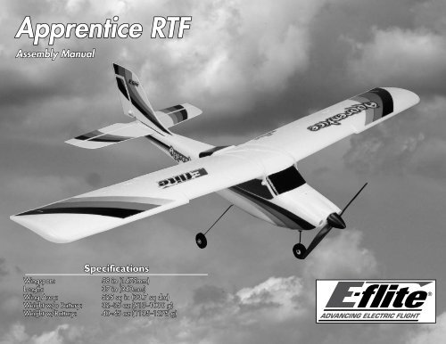
<strong>Apprentice</strong> RTF<br />
Assembly <strong>Manual</strong><br />
Specifications<br />
Wingspan:<br />
58 in (1475mm)<br />
Length:<br />
37 in (940mm)<br />
Wing Area:<br />
525 sq in (33.7 sq dm)<br />
Weight w/o Battery: 32–35 oz (910–1000 g)<br />
Weight w/Battery: 40–45 oz (1135–1275 g)
Table of Contents<br />
Introduction......................................................................... 2<br />
Using the <strong>Manual</strong>................................................................ 2<br />
Contents of Kit/Parts Layout................................................. 3<br />
Required Tools and Adhesives............................................... 3<br />
Optional Accessories........................................................... 3<br />
Note on Lithium Polymer Batteries......................................... 3<br />
Important Warranty Information........................................... 3<br />
Charging the Flight Battery................................................... 4<br />
Tail Installation..................................................................... 6<br />
Landing Gear Installation..................................................... 9<br />
Checking the Receiver........................................................ 10<br />
Wing Installation................................................................ 11<br />
Battery Installation.............................................................. 14<br />
Installing the Transmitter Batteries........................................ 16<br />
Removing the Propeller....................................................... 17<br />
Control Functions............................................................... 19<br />
Centering the Control Surfaces and<br />
Checking Control Direction....................................... 20<br />
Center of Gravity............................................................... 29<br />
Range Test Your Radio........................................................ 30<br />
Flying Your <strong>Apprentice</strong>....................................................... 31<br />
Setting the Control Throws.................................................. 32<br />
Installing the Propeller........................................................ 35<br />
Warning........................................................................... 37<br />
Instructions for Disposal of WEEE by<br />
Users in the European Union.................................... 37<br />
Optional Items for Your <strong>Apprentice</strong>..................................... 38<br />
LiPo Battery Pack Information.............................................. 39<br />
Warranty Information......................................................... 41<br />
Safety, Precautions, and Warnings...................................... 43<br />
2008 Official AMA National Model Aircraft Safety Code.... 44<br />
Building and Flying Notes.................................................. 45<br />
Introduction<br />
The E-flite ® <strong>Apprentice</strong> RTF is a 15-size high wing trainer,<br />
constructed of lightweight, durable Z-Foam . The <strong>Apprentice</strong><br />
ready-to-fly trainer comes with everything needed to go from<br />
purchase directly to the field. This includes the full-range<br />
Spektrum technology DX5e radio with 2.4GHz interference-free<br />
technology and AR500 full-range receiver which will provide you<br />
with years of flying. No building is required for this model. Simply<br />
charge and install the battery, mount the wing and tail, install the<br />
landing gear and go flying.<br />
The <strong>Apprentice</strong> is powered with a 15-size brushless motor that<br />
provides excellent power and performance. This trainer has a flatbottom<br />
wing that produces gentle flight characteristics. This trainer<br />
enables the pilot to learn how to fly through buddy-box training<br />
and progression to aerobatics, as the skills of the pilot allow. The<br />
<strong>Apprentice</strong> is capable of flying mild aerobatics including inverted<br />
flight, performing loops, and rolls. This model is equipped with<br />
tricycle landing gear allowing better ground handling over taildragger<br />
aircraft. This landing gear setup is durable and will also<br />
allow takeoffs and landings on maintained grass runways. This is<br />
a high-quality trainer with an excellent setup, taking the pilot from<br />
beginner to basic aerobatics all from this one-box purchase. Go<br />
from buy to fly with the <strong>Apprentice</strong>.<br />
Using the <strong>Manual</strong><br />
This manual is divided into sections to help make assembly<br />
easier to understand, and to provide breaks between each<br />
major section. In addition, check boxes have been placed next<br />
to each step to keep track of its completion. Steps with a single<br />
circle () are performed once, while steps with two circles (<br />
) indicate that the step will require repeating, such as for a<br />
right or left wing panel, two servos, etc.<br />
Remember to take your time and follow the directions.<br />
The Spektrum trademark is used with<br />
permission of Bachmann Industries, Inc.<br />
2 E-flite <strong>Apprentice</strong> Assembly <strong>Manual</strong>
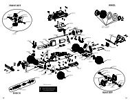
Contents of Kit/Parts Layout<br />
EFL2726<br />
Wing Set<br />
EFL2727<br />
Fuselage<br />
EFL2728<br />
Tail Set<br />
EFL2729<br />
Cowl<br />
EFL2730<br />
Pushrod Set<br />
EFL2731<br />
Nose Gear<br />
EFL2732<br />
Main Landing Gear<br />
EFL2733<br />
Spinner<br />
EFL2734<br />
Motor Mount<br />
EFL2735<br />
5mm Prop Adapter<br />
EFLA1030<br />
30 Amp Pro Switch-mode<br />
BEC Brushless ESC<br />
EFLB1040<br />
3200mAh 3S 11.1v 15C Li-Po Battery<br />
EFLC3010<br />
3 Amp 12V balancing Li-Po charger<br />
EFLM7215<br />
BL15 outrunner, 840 kV motor<br />
EFLP11080E 11 x 8 Electric Propeller<br />
EFLR7130<br />
12g sub micro servo (used on ailerons)<br />
EFLR7140<br />
13g sub micro servo (used on elevator)<br />
EFLR7150<br />
37g standard servo (used on rudder)<br />
SPM5500<br />
DX5e Radio system<br />
SPMAR500<br />
AR500 DSM2 Full-Range Receiver<br />
Tools & Equipment<br />
EFLA250<br />
Required Tools and Adhesives<br />
Or Purchase Separately<br />
Phillips screwdriver: #1<br />
Adjustable wrench<br />
Ruler<br />
EFLA110<br />
EFLC3005<br />
EFLC505<br />
EFLB32003S<br />
EFLP11080E<br />
SPM6805<br />
DYN4055<br />
Parkflyer Tool Assortment, 5-piece<br />
Optional Accessories<br />
Power Meter<br />
Celectra 1- to 3-Cell LiPo Charger<br />
Intelligent 1- to 5-Cell Balancing Charger<br />
3200mAh 3S 11.1V 20C LiPo Battery<br />
11x8 Electric Prop<br />
Trainer Cord<br />
12-Volt, 10-Amp Power Supply<br />
Note on Lithium Polymer Batteries<br />
Lithium Polymer batteries are significantly more<br />
volatile than alkaline or Ni-Cd/Ni-MH batteries used<br />
in RC applications. All manufacturer’s instructions<br />
and warnings must be followed closely. Mishandling<br />
of LiPo batteries can result in fire. Always follow the<br />
manufacturer’s instructions when disposing of Lithium<br />
Polymer batteries.<br />
Important Warranty Information<br />
Please read our Warranty and Liability Limitations section<br />
on Page – before building this product. If you as the<br />
Purchaser or user are not prepared to accept the liability<br />
associated with the use of this Product, you are advised to<br />
return this Product immediately in new and unused condition<br />
to the place of purchase.<br />
E-flite <strong>Apprentice</strong> Assembly <strong>Manual</strong><br />
3
Charging the Flight Battery<br />
Your <strong>Apprentice</strong> can be ready to fly in as little time as it takes<br />
to charge the flight battery. Since this takes approximately 60<br />
minutes, let's get the battery charging right away so it's on<br />
charge while you're assembling your new <strong>Apprentice</strong>. That way<br />
you can start flying as soon as possible.<br />
Required Parts<br />
Charger<br />
3200 3S 11.1V LiPo battery<br />
Power supply or 12-volt battery (not included)<br />
Note: The battery charger can be connected to a power<br />
supply or 12-volt battery. For the pictures in this manual<br />
we will show the use of a power supply.<br />
<br />
1. Connect the charger to a 12-volt battery or 12-volt<br />
power supply. Connect the red lead to the positive (+)<br />
terminal of the power supply or battery. Connect the<br />
black lead to the negative (-) terminal of the power<br />
supply or 12-volt battery. Once your charger has been<br />
correctly powered up, there will be an approximate<br />
3-second delay and then you will hear an audible “beep”<br />
and the green (ready) LED will flash.<br />
4 E-flite <strong>Apprentice</strong> Assembly <strong>Manual</strong>
2. Select the proper number of cells that you will be<br />
charging. Your <strong>Apprentice</strong> includes a 3-cell flight pack,<br />
so set the charger to 3 cells.<br />
<br />
4. Locate the balance charge lead on the battery pack.<br />
The charge lead of a 3-cell LiPo battery will plug into<br />
the larger 4-pin port on the bottom right of the charger.<br />
A 2-cell pack will need to plug into the 3-pin port on<br />
bottom left of the charger. Once the battery is properly<br />
plugged into the correct port, it will beep 3 times if it is a<br />
3-cell, and twice if it is a 2-cell pack. Once this is done,<br />
you are ready to proceed to charge the battery pack.<br />
<br />
3. Set the charge rate for your battery to 3 amps.<br />
Warning: Selecting a charge rate higher than 1x battery<br />
capacity may cause a fire. If the battery capacity is<br />
3000mAh, then set your charger no higher than 3 amps.<br />
E-flite <strong>Apprentice</strong> Assembly <strong>Manual</strong><br />
5
5. Push the start button to begin the charging process.<br />
Once this is done, the charger will make an audible beep<br />
that matches the cell count, and then the red (charge)<br />
LED will begin to flash. Do not adjust the current once the<br />
charger has begun to charge.<br />
Note: At times, the green LED may also flash during<br />
the charging process, indicating that the charger is<br />
balancing one or more of the cells at the same time it<br />
is charging the battery pack. When this is occurring,<br />
the red and green LEDs will both be flashing. It will not<br />
always be necessary for the cells to be balanced.<br />
6. When the battery pack is fully charged, you will hear<br />
an audible beep for about 3 seconds, and the green LED<br />
will be solid. Always unplug the battery from the charger<br />
immediately upon completion. Failure to do so could<br />
cause a fire.<br />
Tail Installation<br />
Required Parts<br />
Fuselage Assembly<br />
Stabilizer/Elevator<br />
Fin/Rudder<br />
2.5mm x 12mm sheet metal screw (2)<br />
Required Tools<br />
Phillips screwdriver: #1<br />
<br />
1. Position the stabilizer on the fuselage. Align the holes<br />
in the stabilizer with the holes in the rear of the fuselage.<br />
The decals on the stabilizer will face toward the top of<br />
the fuselage.<br />
Note: Lithium Polymer batteries, commonly known as<br />
LiPos, are not quite like other batteries.<br />
First, they do not develop any sort of memory<br />
characteristics due to partial use or partial charging.<br />
They can be used as little or as much as needed,<br />
then charged back up to capacity without any loss in<br />
performance.<br />
Second, they do have one quirk that should be<br />
explained. If a LiPo battery is discharged to a voltage<br />
less than about 3.0V per cell (9.0 volts total for the<br />
battery in the <strong>Apprentice</strong>), then it will be permanently<br />
damaged and cannot be restored. The electronic speed<br />
control in the <strong>Apprentice</strong> is pre-set to a cutoff voltage that<br />
will not allow the battery to drain less than this amount.<br />
6 E-flite <strong>Apprentice</strong> Assembly <strong>Manual</strong>
2. Slide the pins on the bottom of the fin through the<br />
holes of the stabilizer and into those in the fuselage.<br />
Make sure to seat the fin completely down on the<br />
horizontal stab. You might need to push the fin down<br />
with some slight pressure to fully seat it.<br />
<br />
3. Use a #1 Phillips screwdriver to install the two<br />
2.5mm x 12mm sheet metal screws that secure the<br />
tail assembly to the fuselage. Tighten the screws until they<br />
stop. Do not overtighten as you may crack the plastic.<br />
E-flite <strong>Apprentice</strong> Assembly <strong>Manual</strong><br />
7
4. Connect the elevator pushrod clevis to the elevator<br />
control horn in the hole that is farthest away from the<br />
elevator. Make sure to slide the silicone retainer onto the<br />
clevis to keep the clevis from popping off of the control<br />
horn.<br />
<br />
5. Connect the rudder pushrod clevis to the rudder<br />
control horn in the hole that is farthest away from the<br />
rudder. Make sure to slide the silicone retainer onto the<br />
clevis to keep the clevis from popping off of the control<br />
horn.<br />
Note: For new pilots, we recommend installing the clevis<br />
for both the elevator and rudder pushrods in the outermost<br />
hole on the control horn.<br />
8 E-flite <strong>Apprentice</strong> Assembly <strong>Manual</strong>
Required Parts<br />
Fuselage Assembly<br />
Main gear w/wheels<br />
Required Tools<br />
Phillips screwdriver: #1<br />
<br />
Landing Gear Installation<br />
Nose gear w/wheel<br />
1. Locate the flat area on the nose gear. This area will be<br />
where the screw will be positioned in the following step.<br />
<br />
2. You will need to back out the screw in the nose wheel<br />
steering arm before sliding in the nose gear wire. Slide<br />
the nose gear into the nose gear bracket. Use a #1<br />
Phillips screwdriver to tighten the screw that secures the<br />
nose gear. Make sure the screw is tightened against the<br />
flat area as indicated in Step 1.<br />
Note: You may need to push the cowling out of the way<br />
slightly to access the screw. The cowl material is flexible<br />
enough to bend a little during this step without damage.<br />
E-flite <strong>Apprentice</strong> Assembly <strong>Manual</strong><br />
9
3. Locate the main gear and press it into the slot in the<br />
fuselage that is behind the battery compartment on the<br />
bottom of the fuselage. You may need to flex the landing<br />
gear wire inwards towards itself to get it to fully seat<br />
inside the slot.<br />
Required Parts<br />
Fuselage Assembly<br />
<br />
Checking the Receiver<br />
1. Check that the servos and speed control are plugged<br />
into the receiver properly. The speed control is plugged<br />
into the slot marked "THRO", the smaller servo in the<br />
slot marked "ELEV", the larger servo in "RUDD" and the<br />
connector that has the two leads for the ailerons into the<br />
slot marked "AILE."<br />
10 E-flite <strong>Apprentice</strong> Assembly <strong>Manual</strong>
Wing Installation<br />
Required Parts<br />
Wing panel (right and left) Wing cover, front<br />
Wing cover, rear Rubber band (8)<br />
Fuselage assembly<br />
<br />
1. Align the carbon wing tube with the socket in the<br />
opposite wing panel. Slide the two panels tightly together.<br />
<br />
2. Locate the front and rear wing covers. The front cover<br />
has a rounded edge, while the rear has a squared edge.<br />
Hint: You may want to practice the next steps before<br />
removing the backing from the adhesive tape on the<br />
wing covers. The adhesive will stick as soon as it touches<br />
the wing surface.<br />
<br />
3. Remove the backing from the adhesive tape on the<br />
front wing cover.<br />
E-flite <strong>Apprentice</strong> Assembly <strong>Manual</strong><br />
11
4. Make sure the two wing panels are pressed tightly<br />
together with no gap between them. Position the front<br />
wing cover in the notch at the front of the wing. Press the<br />
cover down to secure its position on the wing.<br />
<br />
5. Repeat the previous step to install the rear wing cover.<br />
<br />
6. Install the included Y-harness by plugging it into the<br />
Aile port of the receiver.<br />
12 E-flite <strong>Apprentice</strong> Assembly <strong>Manual</strong>
7. Connect the aileron pushrod clevis to the aileron<br />
control horn in the hole that is farthest away from the<br />
aileron. Make sure to slide the silicone retainer onto the<br />
clevis to keep the clevis from popping off of the control<br />
horn. Connect both the right and left aileron linkages at<br />
this time.<br />
<br />
9. Install the first two rubber bands. They should cross as<br />
shown in the image below.<br />
<br />
10. The next two rubber bands will go directly from the<br />
front to the rear of the fuselage, over the wing.<br />
<br />
8. Connect the wires from the aileron servos to the<br />
Y-harness coming from the receiver.<br />
E-flite <strong>Apprentice</strong> Assembly <strong>Manual</strong><br />
13
11. Install the last four rubber bands using the Steps 9<br />
and 10 as a guide. You will install two across (as in step<br />
9) and then two in line (as in step 10), and then two<br />
across (as in step 9) and then two in line (as in step 10),<br />
and so on until there are no more rubber bands.<br />
Battery Installation<br />
Required Parts<br />
Assembled airframe<br />
3200 3S 11.1 V LiPo battery (charged)<br />
<br />
1. Turn the battery hatch keeper 90 degrees to release<br />
the hatch.<br />
14 E-flite <strong>Apprentice</strong> Assembly <strong>Manual</strong>
2. Open the hatch from the rear of the fuselage as<br />
shown. The front of the hatch is hinged so it will not<br />
detach from the fuselage and get lost.<br />
<br />
4. Ensure the battery is slid all the way into the front of<br />
the battery compartment. Use the hook and loop straps to<br />
secure the battery in the fuselage.<br />
<br />
3. Slide the battery into the battery compartment. The<br />
connector will face the back of the airplane.<br />
<br />
5. Close the hatch from the rear of the fuselage. Turn the<br />
battery hatch keeper 90 degrees to secure the hatch.<br />
E-flite <strong>Apprentice</strong> Assembly <strong>Manual</strong><br />
15
Installing the Transmitter Batteries<br />
Required Parts<br />
Transmitter AA battery (4)<br />
<br />
1. Check to make sure the transmitter power switch is in<br />
the "OFF" position.<br />
<br />
3. Remove the battery cover and set it aside so it does<br />
not get lost.<br />
<br />
4. Install the four AA batteries. Note the polarity of the<br />
batteries during their installation.<br />
<br />
2. Slide the cover from the battery compartment.<br />
16 E-flite <strong>Apprentice</strong> Assembly <strong>Manual</strong>
5. Slide the battery cover back into position on the back<br />
of the transmitter.<br />
Required Parts<br />
Fuselage assembly<br />
Required Tools<br />
Adjustable wrench<br />
Removing the Propeller<br />
Important: Before performing any maintainance to the<br />
motor, make sure the battery has been unplugged and<br />
removed from your model to prevent injury. Also remove<br />
the propeller when checking the radio system to prevent<br />
any personal injury if the motor were to start.<br />
<br />
1. Remove the spinner cone from the spinner. It should<br />
snap away from the backplate with a little force.<br />
Note: The installation of the batteries is also covered<br />
in your radio manual. Please read through the radio<br />
manual to familiarize yourself with the operation of your<br />
radio system.<br />
E-flite <strong>Apprentice</strong> Assembly <strong>Manual</strong><br />
17
2. Use an adjustable wrench to remove the nut from the<br />
propeller adapter. Set the nut aside so it does not get lost.<br />
<br />
3. Remove the washer and set it aside with the nut and<br />
spinner cone.<br />
<br />
4. Remove the spinner backplate and set it with the nut,<br />
spinner cone and washer.<br />
18 E-flite <strong>Apprentice</strong> Assembly <strong>Manual</strong>
5. Slide the propeller from the propeller adapter. The<br />
installation of the propeller is the reverse of the previous<br />
steps. Make sure the nut is tightened properly so the<br />
propeller does not depart from your model during flight.<br />
Required Parts<br />
Transmitter<br />
<br />
Control Functions<br />
The following images to identify the controls for both the<br />
Mode 1 and Mode 2 versions of your <strong>Apprentice</strong>.<br />
HI/LO<br />
Rate Switch<br />
Throttle/Aileron Stick<br />
Elevator/Rudder Stick<br />
Rudder Trim<br />
Aileron Trim<br />
Note: Once the radio system has been checked, the<br />
propeller can then be installed. Refer to the section<br />
"Installing the Propeller" later in this manual for details.<br />
Elevator Trim<br />
Reversing Switches<br />
Mix Switch (not used for <strong>Apprentice</strong>)<br />
Mode 1 Transmitter<br />
Throttle Trim<br />
E-flite <strong>Apprentice</strong> Assembly <strong>Manual</strong><br />
19
Throttle/Rudder Stick<br />
Rudder Trim<br />
Throttle Trim<br />
Reversing Switches<br />
Mode 2 Transmitter<br />
Elevator/Aileron Stick<br />
HI/LO<br />
Rate Switch<br />
Aileron Trim<br />
Elevator Trim<br />
Mix Switch (not used for <strong>Apprentice</strong>)<br />
Centering the Control Surfaces and<br />
Checking Control Direction<br />
Required Parts<br />
Assembled airframe<br />
Transmitter<br />
<br />
Flight battery<br />
Note: This section is designed to help you become<br />
acquainted with the operation of the radio in correlation<br />
to the model. If a flight control moves in the incorrect<br />
direction we will instruct you how to change it in the<br />
next section. As always, read through the radio manual<br />
which explains the features of your radio system.<br />
1. Turn the radio on using the power switch on the front<br />
of the transmitter and check that the throttle stick is at its<br />
lowest position. The throttle stick needs to be in the idle/<br />
off position, otherwise the speed control will not arm<br />
in the next step. The DX5e transmitter features digital<br />
trims, so they should be centered when the transmitter is<br />
powered on.<br />
Switch<br />
20 E-flite <strong>Apprentice</strong> Assembly <strong>Manual</strong>
2. Plug the EC3 connector on the flight battery into the<br />
speed control. You will hear a series of beeps or tones<br />
when you plug the battery in. During this process it is<br />
normal for the prop to pulse slightly as the ESC powers<br />
up. Please ensure you are not in line with the prop or in<br />
front of it during power up.<br />
Note: The following steps will ensure your flight controls<br />
are centered for the first flight.<br />
Checking the Elevator (Mode 2)<br />
<br />
3. Center the elevator stick. This is the right stick on the<br />
transmitter. The elevator should not be deflected up or<br />
down, but should be flat with the horizontal stabilizer<br />
when viewed from the side. If the elevator is deflected<br />
up or down you will need to push the silicone keeper<br />
back off the clevis, onto the pushrod. This will enable<br />
you to open the clevis up and remove it from the control<br />
horn. Once removed, screw the clevis in or out to get the<br />
elevator to line up with the stab.<br />
Important: Always use extreme caution around the<br />
propeller when the motor battery is plugged in. A<br />
spinning propeller can cause serious damage or injury.<br />
It is always best to stay behind the propeller and keep<br />
it away from loose objects when the battery and speed<br />
control are connected.<br />
When the battery is connected, you will hear one low<br />
long tone to indicate startup, then the respective number<br />
of medium-length mid tones to indicate the cell count or<br />
a musical tone, followed by three rising tones to indicate<br />
the controller is armed. For more information on your<br />
speed control, refer to the included instructions.<br />
Up—Thread clevis out<br />
Centered<br />
Down—Thread clevis in<br />
E-flite <strong>Apprentice</strong> Assembly <strong>Manual</strong><br />
21
4. Check the movement of the elevator with the radio<br />
system. Pulling the elevator/aileron stick (right stick on<br />
the Mode 2 transmitter) back will make the airplane<br />
elevator move up.<br />
<br />
5. Check the movement of the elevator with the radio<br />
system. Pushing the elevator/aileron stick forward will<br />
make the airplane elevator move down on the Mode 2<br />
transmitter.<br />
22 E-flite <strong>Apprentice</strong> Assembly <strong>Manual</strong>
Checking the Elevator (Mode 1)<br />
<br />
3. Center the elevator stick. This is the left stick on the<br />
transmitter. The elevator should not be deflected up or<br />
down, but should be flat with the horizontal stabilizer<br />
when viewed from the side. If the elevator is deflected<br />
up or down you will need to push the silicone keeper<br />
back off the clevis, onto the pushrod. This will enable<br />
you to open the clevis up and remove it from the control<br />
horn. Once removed, screw the clevis in or out to get the<br />
elevator to line up with the stab.<br />
<br />
4. Check the movement of the elevator with the radio<br />
system. Pulling the elevator/rudder stick (left stick on the<br />
Mode 1 transmitter) back will make the airplane elevator<br />
move up.<br />
E-flite <strong>Apprentice</strong> Assembly <strong>Manual</strong><br />
23
5. Check the movement of the elevator with the radio<br />
system. Pushing the elevator/rudder stick forward will<br />
make the airplane elevator move down on the Mode 1<br />
transmitter.<br />
Checking the Rudder (Mode 1 and 2)<br />
<br />
6. Mode 1 (Rudder/Elevator on left stick): Center the<br />
rudder stick. Thread the clevis in or out on the rudder<br />
pushrod until the rudder is aligned with the fin as shown.<br />
Mode 2 (Rudder/Throttle on left stick): Confirm the<br />
rudder stick is in the down/throttle off position. Thread<br />
the clevis in or out on the rudder pushrod until the rudder<br />
is aligned with the fin as shown.<br />
Right—Thread clevis out<br />
Centered<br />
Left—Thread clevis in<br />
24 E-flite <strong>Apprentice</strong> Assembly <strong>Manual</strong>
7. Check the movement of the rudder using the<br />
transmitter. When the rudder/throttle stick (left side<br />
of the transmitter) is moved right, the rudder should<br />
also move right.<br />
<br />
8. Check the movement of the rudder using the<br />
transmitter. When the left stick is moved left, the<br />
rudder should also move left.<br />
Important: When operating a Mode 2 transmitter<br />
(rudder/throttle on left stick), be very careful that the<br />
left stick is not moved forward when checking the<br />
rudder. Moving the rudder stick forward will result in the<br />
propeller spinning.<br />
E-flite <strong>Apprentice</strong> Assembly <strong>Manual</strong><br />
25
Checking the Steering Trim (Mode 1 and 2)<br />
Note: Checking the steering trim must be done after<br />
the aircraft has been flown and the rudder trimmed for<br />
straight flight at the transmitter. The steering trim is a<br />
mechanical adjustment and should never be corrected<br />
using the rudder trim at the transmitter.<br />
<br />
9. Once the rudder has been trimmed for straight flight,<br />
you can now adjust the steering trim of your <strong>Apprentice</strong>.<br />
Taxi the aircraft to determine if it turns left or right when<br />
the rudder stick is centered. Do not change the rudder<br />
trim at the transmitter. If the aircraft turns right, thread<br />
the clevis IN at the rudder servo, which will shorten the<br />
steering linkage. If the aircraft turns left, thread the clevis<br />
OUT at the rudder servo, which will lengthen the steering<br />
linkage. Adjust until the aircraft will taxi in a straight line<br />
without any rudder control inputs.<br />
Aircraft turns left—<br />
Thread clevis OUT at rudder servo<br />
Aircraft turns right—<br />
Thread clevis IN at rudder servo<br />
26 E-flite <strong>Apprentice</strong> Assembly <strong>Manual</strong>
Checking the Ailerons (Mode 1 and 2)<br />
<br />
10. Center the aileron stick. Thread the clevis in or out on<br />
the aileron pushrod until the ailerons are aligned with the<br />
wing as shown.<br />
<br />
11. Check the movement of the aileron using the<br />
transmitter. When the elevator/aileron stick (Mode 2<br />
transmitter) or throttle/aileron stick (Mode 1 transmitter)<br />
is moved right, the right aileron will move up and the left<br />
aileron will move down.<br />
Up—Thread clevis in<br />
Centered<br />
Down—Thread clevis out<br />
E-flite <strong>Apprentice</strong> Assembly <strong>Manual</strong><br />
27
12. Check the movement of the aileron using the<br />
transmitter. When the aileron/elevator stick (Mode<br />
2 transmitter) or the aileron/throttle stick (Mode 1<br />
transmitter) is moved left, the left aileron will move up<br />
and the right aileron will move down.<br />
Reversing Direction of Flight Controls<br />
If you find any control surface moving in the opposite direction of<br />
what it should (example shown below), use the Servo Reversing<br />
feature of the DX5e to fix the problem. Reversing switches for all<br />
of the control functions are located on the front of the transmitter<br />
below the power switch. Locate the appropriate switch, slide it<br />
to the new position, and check to see if the surface in question is<br />
now moving in the right direction.<br />
28 E-flite <strong>Apprentice</strong> Assembly <strong>Manual</strong>
13. This completes the radio setup section. You may now<br />
power down your airplane and transmitter. To do this<br />
follow these steps.<br />
A. Unplug the aircraft battery<br />
B. Turn transmitter off.<br />
Center of Gravity<br />
An important part of preparing the aircraft for flight is properly<br />
balancing the model.<br />
Caution: Do not inadvertently skip this step!<br />
The recommended Center of Gravity (CG) location for the<br />
<strong>Apprentice</strong> is 3 1 /4-inch (83mm) back from the leading edge of<br />
the top wing. Mark the location for the Center of Gravity on the<br />
bottom of the top wing in the center as shown.<br />
When balancing your <strong>Apprentice</strong>, support the plane upright<br />
at the marks made on the bottom of the wing with your fingers<br />
or a commercially available balancing stand. Move the speed<br />
control and/or receiver as necessary so the model hangs level<br />
or slightly nose down. This is the correct balance point for your<br />
model.<br />
E-flite <strong>Apprentice</strong> Assembly <strong>Manual</strong><br />
29
Range Test Your Radio<br />
<strong>Apprentice</strong> Balanced - No Correction Needed<br />
Before each flying session, and especially with a new model, it<br />
is important to perform a range check. The DX5e incorporates<br />
a range testing system which, when placed in the range check<br />
mode with the trainer switch activated and held, reduces the<br />
output power, allowing a range check.<br />
<br />
1. With the model resting on the ground, stand 30 paces<br />
(approximately 90 feet) away from the model.<br />
<strong>Apprentice</strong> Nose Heavy -<br />
Add Weight to Tail or Move Battery Rearward<br />
<br />
2. Face the model with the transmitter in your normal<br />
flying position. Pull and hold the trainer switch while<br />
toggling the HI/LO Rate Switch four times. The LEDs will<br />
flash and the alarm will sound, indicating the system is in<br />
range check mode.<br />
Trainer Switch<br />
HI/LO Rate Switch<br />
<strong>Apprentice</strong> Tail Heavy -<br />
Add Weight to Nose or Move Battery Forward<br />
After the first flights, the CG position can be adjusted for your<br />
personal preference.<br />
30 E-flite <strong>Apprentice</strong> Assembly <strong>Manual</strong>
3. You should have total control of the model with the<br />
trainer switch pulled at 30 paces (90 feet).<br />
30 paces (90 feet/28 meters)<br />
4. If control issues exist, call the <strong>Horizon</strong> Support Team at<br />
1 877 504 0233 or go to horizonhobby.com to find a<br />
local Spektrum distributor in your country for service.<br />
Flying Your <strong>Apprentice</strong><br />
It is strongly recommended for your first flights to search out the<br />
assistance of a qualified instructor, who will help you through<br />
your first flights and assist you in the basics of Radio Controlled<br />
flight. You can find this guidance at your local hobby dealer’s<br />
store. Your <strong>Apprentice</strong> is capable of flying in winds up to 15 mph<br />
but, for flight training, it is recommended to fly in the lightest<br />
wind possible. You will need to ensure your battery is fully<br />
charged and the model is set up accordingly for your first flight.<br />
Do not attempt to fly the model on a partially charged battery.<br />
Your DX5e can be used with a wide variety of transmitters<br />
when using the buddy box feature. The buddy box feature is<br />
a very useful tool when learning to fly. It allows the instructor<br />
pilot to hold the main transmitter (the DX5e that is included in<br />
your <strong>Apprentice</strong> kit) while you hold another transmitter which is<br />
called the slave transmitter. These two transmitters are connected<br />
together via a buddy cord (SPM6805) which is called out as an<br />
option on page 3 of this manual. Most instructors at your local<br />
flying field will have one of these cords available for your use<br />
the first time out. While you learn to fly, the flight instructor holds<br />
a trainer switch down which gives you (the student) control of<br />
the model. When you encounter any issues in flight or become<br />
disoriented, the flight instructor releases the switch taking over<br />
control of your model in a split second. The end result is that<br />
the model is never in any serious danger of crashing due to this<br />
great feature. The DX5e is compatible with all JR or Spektrum<br />
transmitters when using the buddy box feature.<br />
E-flite <strong>Apprentice</strong> Assembly <strong>Manual</strong><br />
31
Required Parts<br />
Assembled airframe<br />
Transmitter<br />
Setting the Control Throws<br />
Required Tools and Adhesives<br />
Ruler<br />
Charged flight battery<br />
Your transmitter and model come out of the box set up and ready<br />
to fly. Should you need to replace your fuselage or wing due to<br />
a mishap or such, this section will help you reset your control<br />
throws to the factory settings.<br />
Note: Measurements are taken at the widest point on<br />
the surface.<br />
These are general guidelines measured from our own flight tests.<br />
You can experiment with different rates to match your preferred<br />
style of flying. Adjusting of the control throws on the <strong>Apprentice</strong><br />
<strong>15e</strong> is not as critical as it is on other models. The measurements<br />
given in this section are approximations and a place to get close<br />
to when replacing parts and resetting control throws. The location<br />
of the pushrod or clevis on the servo arm and control horn of<br />
the flight control surface are given as they come set from the<br />
factory. With this information you should be able to attain settings<br />
that will be very close to the originals and deliver the flight<br />
performance you have come to expect from the <strong>Apprentice</strong>.<br />
<br />
1. Turn the radio on using the power switch on the front<br />
of the transmitter and check that the throttle stick is at its<br />
lowest position. The throttle stick needs to be in the idle/<br />
off position, otherwise the speed control will not arm in<br />
the next step. The DX5e featuers digital trims, so they<br />
should be centered when the transmitter is powered on.<br />
Switch<br />
32 E-flite <strong>Apprentice</strong> Assembly <strong>Manual</strong>
2. Plug the motor battery into the speed control.<br />
Elevator Throw<br />
<br />
3. Use a ruler to check the control throws on your<br />
elevator. The dimensions are shown below. For your<br />
reference the elevator pushrod is set up in the following<br />
holes: The outside hole on the elevator control horn and<br />
the fourth hole in on the elevator servo arm.<br />
Low Rate:<br />
3/8-inch (9mm) (Up/Down)<br />
Important: Always use extreme caution around the<br />
propeller when the motor battery is plugged in. A<br />
spinning propeller can cause serious damage or injury.<br />
It is always best to stay behind the propeller and keep<br />
it away from loose objects when the battery and speed<br />
control are connected.<br />
High Rate: 3/4-inch (19mm) (Up/Down)<br />
E-flite <strong>Apprentice</strong> Assembly <strong>Manual</strong><br />
33
Rudder Throw<br />
Aileron Throw<br />
<br />
4. Use a ruler to check the control throws on your rudder.<br />
The dimensions are shown below. For your reference<br />
the rudder pushrod is set up in the following holes: The<br />
outside hole on the rudder control horn and the outside<br />
hole on the rudder servo arm.<br />
<br />
5. Use a ruler to check the control throws on the ailerons.<br />
The dimensions are shown below. For your reference the<br />
aileron pushrods are set up in the following holes: The<br />
outside hole on the aileron control horn and the outside<br />
hole on the aileron servo arm.<br />
Low Rate:<br />
1/2-inch (14mm) (Right/Left)<br />
Low Rate:<br />
3/8-inch (9mm) (Up/Down)<br />
High Rate: 1-inch (25mm) (Up/Down)<br />
High Rate: 5/8-inch (16mm) (Up/Down)<br />
34 E-flite <strong>Apprentice</strong> Assembly <strong>Manual</strong>
6. Once all the control throws have been set, make sure<br />
to slide the clevis retainers over the clevises to prevent<br />
them from opening accidentally.<br />
Required Parts<br />
Fuselage assembly<br />
Propeller nut<br />
Spinner cone<br />
Required Tools<br />
Adjustable wrench<br />
Installing the Propeller<br />
Propeller<br />
Propeller washer<br />
Spinner backplate<br />
Important: Before performing any maintainance to the<br />
motor, make sure the battery has been unplugged and<br />
removed from your model to prevent injury.<br />
<br />
1. Slide the propeller on the propeller adapter.<br />
<br />
7. For your reference the nose wheel steering pushrod is<br />
set up in the following holes: The fixed position hole on<br />
the nose wheel steering arm and the outside hole on the<br />
rudder servo arm.<br />
E-flite <strong>Apprentice</strong> Assembly <strong>Manual</strong><br />
35
2. Slide the spinner backplate on the propeller adapter.<br />
<br />
4. Thread the nut on the propeller adapter. Use an<br />
adjustable wrench to tighten the nut. Make sure the nut is<br />
tightened properly so the propeller does not depart from<br />
your model during flight.<br />
<br />
3. Install the washer on the propeller shaft.<br />
36 E-flite <strong>Apprentice</strong> Assembly <strong>Manual</strong>
5. Snap the spinner cone on the spinner backplate. It<br />
should snap on the backplate using a little force.<br />
Warning<br />
An RC aircraft is not a toy! If misused, it can cause serious<br />
bodily harm and damage to property. Fly only in open areas,<br />
preferably at AMA (Academy of Model Aeronautics) approved<br />
flying sites, following all instructions included with your radio.<br />
Keep loose items that can get entangled in the propeller away<br />
from the prop, including loose clothing, or other objects such as<br />
pencils and screwdrivers. Especially keep your hands away from<br />
the propeller.<br />
Instructions for Disposal of WEEE by<br />
Users in the European Union<br />
This product must not be disposed of with other waste. Instead,<br />
it is the user’s responsibility to dispose of their waste equipment<br />
by handing it over to a designated collection point for the<br />
recycling of waste electrical and electronic equipment. The<br />
separate collection and recycling of your waste equipment at<br />
the time of disposal will help to conserve natural resources and<br />
ensure that it is recycled in a manner that protects human health<br />
and the environment. For more information about where you<br />
can drop off your waste equipment for recycling, please contact<br />
your local city office, your household waste disposal service or<br />
where you purchased the product.<br />
E-flite <strong>Apprentice</strong> Assembly <strong>Manual</strong><br />
37
Optional Items for Your <strong>Apprentice</strong><br />
E-flite 32003S Battery<br />
As you have selected the world of electric power to begin your<br />
RC experience, we thought it would be good to show you some<br />
optional equipment that will help you grow and enjoy the world<br />
of electric flight. The equipment included with your <strong>Apprentice</strong><br />
works very well and will serve your needs without hesitation. All<br />
of the items shown in this section are available from your local<br />
hobby dealer.<br />
The charger listed in this section will help you achieve a<br />
more versatile charging network for you to operate your<br />
electric-powered models.<br />
E-flite 1-to 5-cell LiPo Charger<br />
The E-flite 32003S LiPo battery is a high quality replacement<br />
battery that can be charged by the charger listed in this section<br />
or the charger supplied with your model. Ask for part number<br />
EFLB32003S from your local hobby dealer.<br />
The E-flite LiPo balancing charger is capable of charging<br />
up to 5-cell LiPo packs. Ask for part number EFLC505 from<br />
your local hobby dealer. AC to 12V DC power adapter also<br />
available (THP1205P).<br />
38 E-flite <strong>Apprentice</strong> Assembly <strong>Manual</strong>
Warning!<br />
LiPo Battery Pack Information<br />
Lithium Polymer (LiPo) batteries are significantly more volatile than<br />
other rechargeable batteries used in RC applications. Failure to read<br />
and follow these instructions and safety precautions may result in<br />
fire, personal injury and damage to property. E-flite, <strong>Horizon</strong><br />
<strong>Hobby</strong>, Inc., its retailers, and any other representatives, assume<br />
absolutely no liability for use of this product or failure to comply with<br />
these instructions and precautions.<br />
If you are not prepared to accept complete liability for the<br />
purchase and/or use of this product, you are advised to return<br />
it new and unused to the place of purchase immediately.<br />
Never ship batteries without the expressed permission of<br />
the recipient. Batteries carrying 25% or more charge cannot<br />
be shipped safely. Batteries which are damaged cannot be<br />
shipped safely. Damage or loss due to unsafe shipping is the<br />
legal responsibility of the person who shipped the product.<br />
CAUTION: This product may ignite under certain conditions.<br />
Please read all safety precautions before use.<br />
Please call 877-504-0233 with any questions or concerns<br />
regarding this product or warranty.<br />
European Union<br />
Electronics and engines requiring inspection or repair should be<br />
shipped to the following address:<br />
<strong>Horizon</strong> <strong>Hobby</strong> UK<br />
Units 1-4 Ployters Rd<br />
Staple Tye<br />
Southern WayHarlow<br />
Essex CM18 7NS<br />
United Kingdom<br />
<strong>Horizon</strong> <strong>Hobby</strong> Deutschland GmbH<br />
Otto Hahn Str. 9a<br />
25337 Elmshorn<br />
Germany<br />
Usage Guidelines, Warnings and Safety Precautions<br />
• LiPo batteries may explode if damaged or if disposed<br />
of improperly.<br />
• Always inspect batteries before charging.<br />
• Never charge or use a LiPo battery or pack that shows<br />
any damage or disfigurement of any kind. Swelling is a<br />
sign of internal damage. Any breach of protective cover,<br />
wiring or plugs is also reason to discontinue use (see<br />
Disposal Instructions).<br />
• Use specific Lithium Polymer charger only. Do not use a Ni-Cd<br />
or Ni-MH charger – failure to do so may cause a fire, which<br />
may result in personal injury and/or property damage.<br />
• Never charge around or in the area of any flammable or<br />
combustible materials.<br />
• Always charge LiPo batteries in or on fire-resistant materials<br />
or containers.<br />
• Never leave battery and charger unattended while in use.<br />
Improper charging or discharging of LiPo batteries could result<br />
in fire.<br />
• Constantly monitor the temperature of the battery pack while<br />
charging. If the battery becomes hot to the touch, discontinue<br />
charging immediately. Disconnect the battery from the charger<br />
and observe it in a safe place for at least 15 minutes.<br />
• If at any time you see a battery starting to balloon or swell up,<br />
discontinue charging or using immediately.<br />
Please call +44 0 1279 641 097 or sales@horizonhobby.co.uk with<br />
any questions or concerns regarding this product or warranty.<br />
E-flite <strong>Apprentice</strong> Assembly <strong>Manual</strong><br />
39
• Lithium batteries can still ignite after at least 45 minutes<br />
due to a delayed chemical reaction. If battery is damaged or<br />
overheats, observe the battery in a safe area outside of any<br />
building or vehicle and away from combustible material.<br />
• Do not allow children to charge LiPo battery packs.<br />
• Do not allow children to use LiPo batteries without<br />
adult supervision.<br />
• Shorting the wire leads can cause fire. If you accidentally<br />
short the wires, the battery must be placed in a safe area for<br />
observation for at least 15 minutes.<br />
• Never store or charge a battery pack where the temperature<br />
will go below 32 degrees Fahrenheit or above 130 degrees<br />
Fahrenheit. Extreme temperatures will damage the battery pack<br />
and may cause a fire. Battery performance may be diminished<br />
by less extreme temperatures.<br />
• Any of the following may cause the battery to be damaged<br />
resulting in battery swelling, leaking, or fire:<br />
• Bending, folding or dropping of the battery<br />
• Damaging the edge seal of the battery<br />
• Taking apart the battery<br />
• Mixing cells of differing chemistry, or types, or sizes<br />
• Mixing cells of different ages<br />
Crash Damage<br />
If there are signs of smoke or overheating, DO NOT go<br />
near the battery or equipment until it has been observed from<br />
a safe distance for at least 15 minutes. Once it is safe, remove<br />
the battery and check for damage. Dispose of damaged<br />
batteries appropriately.<br />
Swollen Batteries<br />
Immediately stop using or charging. If the battery is not warm<br />
to the touch, move it to an open safe area and observe it for at<br />
least 15 minutes. Be VERY CAREFUL when moving the batteries.<br />
Do NOT put ANY pressure on the batteries or covering as this<br />
may cause fire.<br />
Additional Information & Guidelines<br />
1. Battery temperature the best indicator for safety. The E-flite LiPo<br />
battery’s temperature should never drop below 32 degrees<br />
Fahrenheit or go above 130 degrees Fahrenheit while charging<br />
or discharging.<br />
2. Changing plugs is NOT recommended as the process is<br />
dangerous and any error can cause immediate fire. Improperly<br />
installed plugs can also cause fire due to shorts, reverse polarity<br />
or other improper handling which can cause battery damage.<br />
3. Batteries should be stored in a vented, fire-resistant container.<br />
Each pack should be stored in its own locked plastic bag within<br />
the container. The number of battery packs per container<br />
should be extremely limited to avoid chain reactions. Storage<br />
temperatures should not fall below 32 degrees F or above<br />
130 degrees F. Damaged batteries must be kept at even more<br />
ambient temperatures. High temperatures may cause fire even<br />
with undamaged batteries.<br />
Battery Disposal<br />
LiPo batteries require special handling for safe disposal. The<br />
following are basic instructions for safe disposal. For more<br />
detailed safety, disposal and recycling information please go to:<br />
www.rbrc.org or www.earth911.org.<br />
40 E-flite <strong>Apprentice</strong> Assembly <strong>Manual</strong>
Basic Disposal Instructions<br />
Before discarding any LiPo battery it must be rendered safe.<br />
The following steps must be taken to avoid damage or injury to<br />
yourself, your property and anyone who comes in contact with<br />
the battery.<br />
If the battery is undamaged but no longer useful:<br />
1. Discharge the battery to a maximum of 2.5V using a slow, safe<br />
discharge method.<br />
2. Leave battery uncharged and retest after at least 24 hours.<br />
Many batteries experience “rebound” and may have more<br />
than 2.5V after 24 hours. If the battery is over 2.5V, repeat the<br />
procedure until the battery is 2.5V or less.<br />
3. Insulate each wire lead with electrical tape or other<br />
appropriate material.<br />
4. Assure that wire leads cannot touch each other by taping them<br />
to opposite sides of the battery.<br />
5. Place battery in a sealed plastic bag and place plastic bag in a<br />
vented, fire-safe container.<br />
6. Use fire-safe container to deliver battery to a recycling center<br />
authorized for Lithium Polymer batteries. Please note that not<br />
all battery recycling services include LiPo’s. If no LiPo recycling<br />
facility is available in your area, contact your state or local<br />
Hazmat agency for instructions.<br />
7. If the battery or wiring is damaged please contact your<br />
state or local Hazmat facility for instructions. Batteries must<br />
be rendered safe before being transported or recycled. Do<br />
NOT transport or ship batteries which have more than 2.5V<br />
charge OR that show signs of damage without following the<br />
instructions given by authorities. Damaged batteries should be<br />
rendered as safe as possible and stored in a vented fireproof<br />
container until recycled.<br />
Warranty Period<br />
Warranty Information<br />
<strong>Horizon</strong> <strong>Hobby</strong>, Inc., (<strong>Horizon</strong>) warranties that the Products purchased<br />
(the “Product”) will be free from defects in materials and workmanship<br />
at the date of purchase by the Purchaser.<br />
Limited Warranty<br />
(a) This warranty is limited to the original Purchaser ("Purchaser") and<br />
is not transferable. REPAIR OR REPLACEMENT AS PROVIDED UNDER<br />
THIS WARRANTY IS THE EXCLUSIVE REMEDY OF THE PURCHASER.<br />
This warranty covers only those Products purchased from an<br />
authorized <strong>Horizon</strong> dealer. Third party transactions are not covered<br />
by this warranty. Proof of purchase is required for warranty claims.<br />
Further, <strong>Horizon</strong> reserves the right to change or modify this warranty<br />
without notice and disclaims all other warranties, express or implied.<br />
(b) Limitations- HORIZON MAKES NO WARRANTY OR<br />
REPRESENTATION, EXPRESS OR IMPLIED, ABOUT NON-<br />
INFRINGEMENT, MERCHANTABILITY OR FITNESS FOR A<br />
PARTICULAR PURPOSE OF THE PRODUCT. THE PURCHASER<br />
ACKNOWLEDGES THAT THEY ALONE HAVE DETERMINED THAT<br />
THE PRODUCT WILL SUITABLY MEET THE REQUIREMENTS OF THE<br />
PURCHASER’S INTENDED USE.<br />
(c) Purchaser Remedy- <strong>Horizon</strong>'s sole obligation hereunder<br />
shall be that <strong>Horizon</strong> will, at its option, (i) repair or (ii) replace, any<br />
Product determined by <strong>Horizon</strong> to be defective. In the event of a<br />
defect, these are the Purchaser's exclusive remedies. <strong>Horizon</strong> reserves<br />
the right to inspect any and all equipment involved in a warranty<br />
claim. Repair or replacement decisions are at the sole discretion of<br />
<strong>Horizon</strong>. This warranty does not cover cosmetic damage or damage<br />
due to acts of God, accident, misuse, abuse, negligence, commercial<br />
use, or modification of or to any part of the Product. This warranty<br />
does not cover damage due to improper installation, operation,<br />
maintenance, or attempted repair by anyone other than <strong>Horizon</strong>.<br />
Return of any goods by Purchaser must be approved in writing by<br />
<strong>Horizon</strong> before shipment.<br />
E-flite <strong>Apprentice</strong> Assembly <strong>Manual</strong><br />
41
Damage Limits<br />
HORIZON SHALL NOT BE LIABLE FOR SPECIAL, INDIRECT OR<br />
CONSEQUENTIAL DAMAGES, LOSS OF PROFITS OR PRODUCTION<br />
OR COMMERCIAL LOSS IN ANY WAY CONNECTED WITH THE<br />
PRODUCT, WHETHER SUCH CLAIM IS BASED IN CONTRACT,<br />
WARRANTY, NEGLIGENCE, OR STRICT LIABILITY. Further, in no<br />
event shall the liability of <strong>Horizon</strong> exceed the individual price of the<br />
Product on which liability is asserted. As <strong>Horizon</strong> has no control over<br />
use, setup, final assembly, modification or misuse, no liability shall be<br />
assumed nor accepted for any resulting damage or injury. By the act<br />
of use, setup or assembly, the user accepts all resulting liability.<br />
If you as the Purchaser or user are not prepared to accept the<br />
liability associated with the use of this Product, you are advised to<br />
return this Product immediately in new and unused condition to the<br />
place of purchase.<br />
Law: These Terms are governed by Illinois law (without regard to<br />
conflict of law principals).<br />
Safety Precautions<br />
This is a sophisticated hobby Product and not a toy. It must be<br />
operated with caution and common sense and requires some basic<br />
mechanical ability. Failure to operate this Product in a safe and<br />
responsible manner could result in injury or damage to the Product<br />
or other property. This Product is not intended for use by children<br />
without direct adult supervision. The Product manual contains<br />
instructions for safety, operation and maintenance. It is essential to<br />
read and follow all the instructions and warnings in the manual, prior<br />
to assembly, setup or use, in order to operate correctly and avoid<br />
damage or injury.<br />
Questions, Assistance, and Repairs<br />
Your local hobby store and/or place of purchase cannot provide<br />
warranty support or repair. Once assembly, setup or use of the<br />
Product has been started, you must contact <strong>Horizon</strong> directly. This will<br />
enable <strong>Horizon</strong> to better answer your questions and service you in the<br />
event that you may need any assistance. For questions or assistance,<br />
please direct your email to productsupport@horizonhobby.com, or call<br />
877.504.0233 toll free to speak to a service technician.<br />
Inspection or Repairs<br />
If this Product needs to be inspected or repaired, please call for a<br />
Return Merchandise Authorization (RMA). Pack the Product securely<br />
using a shipping carton. Please note that original boxes may be<br />
included, but are not designed to withstand the rigors of shipping<br />
without additional protection. Ship via a carrier that provides tracking<br />
and insurance for lost or damaged parcels, as <strong>Horizon</strong> is not<br />
responsible for merchandise until it arrives and is accepted<br />
at our facility. A Service Repair Request is available at www.<br />
horizonhobby.com on the “Support” tab. If you do not have internet<br />
access, please include a letter with your complete name, street<br />
address, email address and phone number where you can be reached<br />
during business days, your RMA number, a list of the included items,<br />
method of payment for any non-warranty expenses and a brief<br />
summary of the problem. Your original sales receipt must also be<br />
included for warranty consideration. Be sure your name, address, and<br />
RMA number are clearly written on the outside of the shipping carton.<br />
Warranty Inspection and Repairs<br />
To receive warranty service, you must include your original<br />
sales receipt verifying the proof-of-purchase date. Provided warranty<br />
conditions have been met, your Product will be repaired or replaced<br />
free of charge. Repair or replacement decisions are at the sole<br />
discretion of <strong>Horizon</strong> <strong>Hobby</strong>.<br />
Non-Warranty Repairs<br />
Should your repair not be covered by warranty the repair<br />
will be completed and payment will be required without<br />
notification or estimate of the expense unless the expense<br />
exceeds 50% of the retail purchase cost. By submitting the<br />
item for repair you are agreeing to payment of the repair without<br />
notification. Repair estimates are available upon request. You must<br />
include this request with your repair. Non-warranty repair estimates<br />
will be billed a minimum of ½ hour of labor. In addition you will be<br />
billed for return freight. Please advise us of your preferred method of<br />
payment. <strong>Horizon</strong> accepts money orders and cashiers checks, as well<br />
as Visa, MasterCard, American Express, and Discover cards.<br />
42 E-flite <strong>Apprentice</strong> Assembly <strong>Manual</strong>
If you choose to pay by credit card, please include your credit card<br />
number and expiration date. Any repair left unpaid or unclaimed<br />
after 90 days will be considered abandoned and will be disposed of<br />
accordingly. Please note: non-warranty repair is only available<br />
on electronics and model engines.<br />
Electronics and engines requiring inspection or repair should be<br />
shipped to the following address:<br />
<strong>Horizon</strong> Service Center<br />
4105 Fieldstone Road<br />
Champaign, Illinois 61822<br />
or<br />
<strong>Horizon</strong> <strong>Hobby</strong> UK<br />
Units 1-4, Ployters Road<br />
Staple Tye - Southern Way<br />
Harlow<br />
Essex<br />
CM187NS<br />
United Kingdom<br />
or<br />
<strong>Horizon</strong> Technischer Service<br />
Otto-Hahn-Str. 9a<br />
25337 Elmshorn<br />
Germany<br />
Telephone: +49 4121 46199 66<br />
Fax: +49 4121 46199 70<br />
Mail: service@horizonhobby.de<br />
All other Products requiring warranty inspection or repair should be<br />
shipped to the following address:<br />
<strong>Horizon</strong> Support Team<br />
4105 Fieldstone Road<br />
Champaign, Illinois 61822<br />
Please call 1 877 504 0233 or visit horizonhobby.com to find<br />
our distributor for your country for support with any questions<br />
or concerns regarding this product or warranty.<br />
Safety, Precautions, and Warnings<br />
As the user of this product, you are solely responsible for<br />
operating it in a manner that does not endanger yourself<br />
and others or result in damage to the product or the property<br />
of others.<br />
Carefully follow the directions and warnings for this and any<br />
optional support equipment (chargers, rechargeable battery<br />
packs, etc.) that you use.<br />
This model is controlled by a radio signal that is subject to<br />
interference from many sources outside your control. This<br />
interference can cause momentary loss of control so it is<br />
necessary to always keep a safe distance in all directions around<br />
your model, as this margin will help to avoid collisions or injury.<br />
• Always operate your model in an open area away from cars,<br />
traffic or people.<br />
• Avoid operating your model in the street where injury or<br />
damage can occur.<br />
• Never operate the model out into the street or populated areas<br />
for any reason.<br />
• Never operate your model with low transmitter batteries.<br />
• Carefully follow the directions and warnings for this and any<br />
optional support equipment (chargers, rechargeable battery<br />
packs, etc.) that you use.<br />
• Keep all chemicals, small parts and anything electrical out of<br />
the reach of children.<br />
• Moisture causes damage to electronics. Avoid water exposure<br />
to all equipment not specifically designed and protected for<br />
this purpose.<br />
E-flite <strong>Apprentice</strong> Assembly <strong>Manual</strong><br />
43
2008 Official AMA National<br />
Model Aircraft Safety Code<br />
GENERAL<br />
1) I will not fly my model aircraft in sanctioned events, air shows<br />
or model flying demonstrations until it has been proven to be<br />
airworthy by having been previously, successfully flight tested.<br />
2) I will not fly my model higher than approximately 400 feet within 3<br />
miles of an airport without notifying the airport operator. I will give<br />
right-of-way and avoid flying in the proximity of full-scale aircraft.<br />
Where necessary, an observer shall be utilized to supervise flying<br />
to avoid having models fly in the proximity of full-scale aircraft.<br />
3) Where established, I will abide by the safety rules for the flying<br />
site I use, and I will not willfully or deliberately fly my models in a<br />
careless, reckless and/or dangerous manner.<br />
4) The maximum takeoff weight of a model is 55 pounds, except<br />
models flown under Experimental Aircraft rules.<br />
5) I will not fly my model unless it is identified with my name and<br />
address or AMA number on or in the model. (This does not apply<br />
to models while being flown indoors.)<br />
6) I will not operate models with metal-bladed propellers or with<br />
gaseous boosts, in which gases other than air enter their internal<br />
combustion engine(s); nor will I operate models with extremely<br />
hazardous fuels such as those containing tetranitromethane or<br />
hydrazine.<br />
RADIO CONTROL<br />
1) I will have completed a successful radio equipment ground range<br />
check before the first flight of a new or repaired model.<br />
2) I will not fly my model aircraft in the presence of spectators until I<br />
become a qualified flier, unless assisted by an experienced helper.<br />
3) At all flying sites a straight or curved line(s) must be established<br />
in front of which all flying takes place with the other side for<br />
spectators. Only personnel involved with flying the aircraft are<br />
allowed at or in front of the flight line. Intentional flying behind the<br />
flight line is prohibited.<br />
4) I will operate my model using only radio control frequencies<br />
currently allowed by the Federal Communications Commission.<br />
(Only properly licensed Amateurs are authorized to operate<br />
equipment on Amateur Band frequencies.)<br />
5) Flying sites separated by three miles or more are considered safe<br />
from site-to-site interference, even when both sites use the same<br />
frequencies. Any circumstances under three miles separation<br />
require a frequency management arrangement, which may be<br />
either an allocation of specific frequencies for each site or testing<br />
to determine that freedom from interference exists. Allocation plans<br />
or interference test reports shall be signed by the parties involved<br />
and provided to AMA Headquarters.<br />
Documents of agreement and reports may exist between (1) two<br />
or more AMA Chartered Clubs, (2) AMA clubs and individual<br />
AMA members not associated with AMA Clubs, or (3) two or<br />
more individual AMA members.<br />
6) For Combat, distance between combat engagement line<br />
and spectator line will be 500 feet per cubic inch of engine<br />
displacement. (Example: .40 engine = 200 feet.); electric motors<br />
will be based on equivalent combustion engine size. Additional<br />
safety requirements will be per the RC Combat section of the<br />
current Competition Regulations.<br />
7) At air shows or model flying demonstrations, a single straight line<br />
must be established, one side of which is for flying, with the other<br />
side for spectators.<br />
8) With the exception of events flown under AMA Competition rules,<br />
after launch, except for pilots or helpers being used, no powered<br />
model may be flown closer than 25 feet to any person.<br />
9) Under no circumstances may a pilot or other person touch a<br />
powered model in flight.<br />
44 E-flite <strong>Apprentice</strong> Assembly <strong>Manual</strong>
Building and Flying Notes<br />
E-flite <strong>Apprentice</strong> Assembly <strong>Manual</strong><br />
45
Building and Flying Notes<br />
46 E-flite <strong>Apprentice</strong> Assembly <strong>Manual</strong>
Building and Flying Notes<br />
E-flite <strong>Apprentice</strong> Assembly <strong>Manual</strong><br />
47
13464.1<br />
© 2008 <strong>Horizon</strong> <strong>Hobby</strong>, Inc.<br />
4105 Fieldstone Road<br />
Champaign, Illinois 61822<br />
1 877 504 0233<br />
horizonhobby.com<br />
E-fliteRC.com