SERVICE MANUAL - Stag ICP AG
SERVICE MANUAL - Stag ICP AG
SERVICE MANUAL - Stag ICP AG

You also want an ePaper? Increase the reach of your titles
YUMPU automatically turns print PDFs into web optimized ePapers that Google loves.
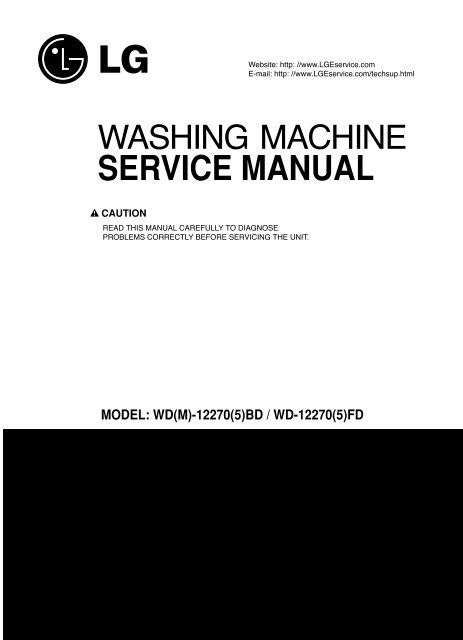
Website: http: //www.LGEservice.com<br />
E-mail: http: //www.LGEservice.com/techsup.html<br />
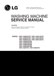
WASHING MACHINE<br />
<strong>SERVICE</strong> <strong>MANUAL</strong><br />
!<br />
CAUTION<br />
READ THIS <strong>MANUAL</strong> CAREFULLY TO DI<strong>AG</strong>NOSE<br />
PROBLEMS CORRECTLY BEFORE SERVICING THE UNIT.<br />
MODEL: WD(M)-12270(5)BD / WD-12270(5)FD<br />
100
FEB. 2004 PRINTED IN KOREA<br />
P/No.:3828ER3027E<br />
101
CONTENTS<br />
1. SPECIFICATIONS .........................................................................................................................3<br />
2. FEATURES & TECHNICAL EXPLANATION ................................................................................ 4<br />
3. PARTS IDENTIFICATION ............................................................................................................ 7<br />
4. INSTALLATION & TEST ............................................................................................................... 8<br />
5. WIRING DI<strong>AG</strong>RAM/PROGRAM CHART .....................................................................................11<br />
6. OPERATION ................................................................................................................................12<br />
7. TROUBLESHOOTING.................................................................................................................14<br />
7-1. BEFORE PERFORMING <strong>SERVICE</strong> ...................................................................................14<br />
7-2. QC TEST MODE.................................................................................................................14<br />
7-3. HOW TO CHECK THE WATER LEVEL FREQUENCY ......................................................14<br />
7-4. ERROR DISPLAY ...............................................................................................................15<br />
8. ERROR DI<strong>AG</strong>NOSIS AND CHECK LIST ....................................................................................17<br />
8-1. DI<strong>AG</strong>NOSIS AND SOLUTION FOR ABNORMAL OPERATION ........................................17<br />
8-2. FAULT DI<strong>AG</strong>NOSIS AND TROUBLESHOOTING ..............................................................20<br />
9. DISASSEMBLY INSTRUCTIONS ...............................................................................................29<br />
10. EXPLODED VIEW .....................................................................................................................38<br />
10-1. CABINET & CONTROL PANEL ASSEMBLY....................................................................38<br />
10-2. DRUM & TUB ASSEMBLY................................................................................................39<br />
10-3. DISPENSER ASSEMBLY .................................................................................................40<br />
2
1. SPECIFICATIONS<br />
ITEM<br />
WD(M)-12270(5)BD, WD-12270(5)FD<br />
COLOR<br />
BLUE WHITE<br />
POWER SUPPLY<br />
AC 220-240V~, 50Hz<br />
PRODUCT WEIGHT<br />
86 kg<br />
ELECTRIC POWER<br />
WASHING<br />
200 W<br />
CONSUMTION<br />
DRAIN MOTOR<br />
37 W<br />
WASH HEATER<br />
2200 W<br />
WASH<br />
42 rpm<br />
REVOLUTION SPEED<br />
SPIN<br />
1200 rpm<br />
CYCLES 9<br />
WASH/RINSE TEMPERATURES 5<br />
SPIN SPEEDS 5<br />
OPTIONS<br />
CUSTOM PROGRAM<br />
WATER CIRCULATION<br />
OPERATIONAL WATER PRESSURE<br />
CONTROL TYPE<br />
WASH CAPACITY<br />
DIMENSIONS<br />
DELAY WASH<br />
DOOR SWITCH TYPE<br />
WATER LEVEL<br />
LAUNDRY LOAD SENSING<br />
ERROR DI<strong>AG</strong>NOSIS<br />
AUTO POWER OFF<br />
CHILD LOCK<br />
Bio, Soak, Pre Wash, Rinse+Spin, Spin Only<br />
Incorporated<br />
Incorporated<br />
30-1000 kPa<br />
Electronic<br />
10 kg<br />
686 m(W) x 767 m(D) x 982m(H)<br />
From 3 hours to 19 hours<br />
PTC + Solenoid<br />
10 steps (by sensor)<br />
Incorporated<br />
Incorporated<br />
Incorporated<br />
Incorporated<br />
3
2. FEATURES & TECHNICAL EXPLANATION<br />
2-1. FEATURES<br />
Direct Drive System<br />
The advanced Brushless DC motor directly drives the drum<br />
without belt and pulley.<br />
Tilted Drum and Extra Large Door Opening<br />
The tilted drum and extra large door opening make it possible<br />
to load and unload easily.<br />
Water Circulation<br />
Spray detergent solution and water onto the load repeatedly.<br />
Clothes are soaked more quickly and thoroughly during the wash cycle.<br />
Detergent suds are eliminated more easily by the water shower<br />
during rinse cycle. The water circulation system uses both<br />
water and detergent more efficiently.<br />
RollerJets<br />
The washing ball enhances wash performance and reduces<br />
damage to clothing. The jets spray and help tumble clothes to enhance<br />
washing performance while maintaining fabric care.<br />
Automatic Wash Load Detection<br />
Automatically detects the load and optimizes the washing time.<br />
Built-in Heater<br />
The internal heater automatically heats the water to the optimum<br />
temperature on selected cycles.<br />
<br />
<br />
Child Lock<br />
The Child lock feature prevents children from pressing any buttons<br />
to change the settings during operation.<br />
4
2-2. NEURO FUZZY WASHING TIME OPTIMIZATION<br />
To get the best washing performance, optimal time is determined by the water temperature,<br />
the selected washing temperature, and the size of the load.<br />
water<br />
temperature<br />
washing time<br />
selected<br />
washing<br />
temperature<br />
NEURO-<br />
FUZZY<br />
rinsing time<br />
the best<br />
washing<br />
performance<br />
load<br />
size<br />
spin rhythm, time<br />
SENSING PROCESSING DETERMINATION EFFECT<br />
2-3. WATER LEVEL CONTROL<br />
This model incorporates a pressure sensor which can sense the water level in the tub.<br />
The water supply is stopped when the water level reaches the preset level, the washing<br />
program then proceeds.<br />
Spinning does not proceed until the water in the tub drains to a certain level.<br />
2-4. DOOR CONTROL<br />
The door can be opened by pulling the door handle whenever washer is not in operation.<br />
When the cycle is completed, the DOOR LOCKED light will turn off.<br />
If a power failure has occurred while in operation, the door will unlock after 5 minutes.<br />
Clicking sounds can be heard when the door is locked/unlocked.<br />
5
2-5. THE DOOR CAN NOT BE OPENED<br />
While program is operating<br />
When a power failed and power plug is taken out in operation<br />
While Door Lock lights turn on.<br />
White the motor is in the process of intertial rotating, through the operation is paused.<br />
2-6. DOOR LOCKED LAMP LIGHTS<br />
When the frequency of water level is lower than 22.9 kHz<br />
(It can be canceled when the frequency is more than 23.8 kHz)<br />
When the temperature inside the tub is higher than 45 °C and water level is not 25.5 kHz<br />
(It can be canceled when the water level is 25.5 kHz or the temperature inside the tub is lower than 40 °C)<br />
2-7. CHILD LOCK<br />
Use this option to prevent unwanted use of the washer. Press and hold Option and Rinse button for 3<br />
seconds to lock/unlock control.<br />
When Child lock is set, CHILD LOCK lights and all buttons are disabled except the Power<br />
You can lock the washer while it is operating.<br />
button.<br />
2-8. WATER CIRCULATION<br />
When Washing and Rinsing function of shower at the upper part of Gasket.<br />
When Washing, it continuously operates for 3 minutes and intermittently.<br />
When Rinsing, it continuously operates after completion of water supply.<br />
6
3. PARTS IDENTIFICATION<br />
ACCESSORIES<br />
7
4. INSTALLATION & TEST<br />
Before servicing, ask the customer what the trouble is.<br />
Check the setup (power supply is 220-240V AC, remove the transit bolts....).<br />
Check with the troubleshooting guide.<br />
Plan your service method by referring to the disassembly instructions.<br />
Service the unit.<br />
After servicing, operate the appliance to see whether it functions correctly.<br />
STANDARD INSTALLATION<br />
The appliance should be installed as follows:<br />
REMOVE THE SHIPPING INSTALL THE APPLIANCE ADJUST THE<br />
BOLTS ON A FLAT AND FIRM SURFACE LEVELING<br />
Remove the 4 shipping bolts<br />
with the supplied wrench.<br />
Do first lower side to remove easily.<br />
Turn the leveling feet to adjust<br />
the appliance.<br />
Keep the shipping bolts and<br />
spanner for future use.<br />
Insert the 4 caps<br />
(provided) into the hole.<br />
Turn clockwise to raise;<br />
counterclockwise to lower.<br />
8
HOW TO CONNECT THE INLET HOSE<br />
Verify that the rubber washer is inside of the<br />
valve connector.<br />
Tighten the inlet hose securely to prevent leaks.<br />
CONNECT THE DRAIN HOSE<br />
Make sure that the hose is not twisted.<br />
Avoid submerging the end of the hose.<br />
The end of the drain hose should be placed less than 100 cm from the floor.<br />
CONNECT POWER PLUG<br />
Connect the power plug to the wall outlet.<br />
Avoid connecting several electric devices, as<br />
doing so may cause a fire.<br />
9
TEST OPERATION<br />
Preparation for Press the POWER button. Press the START/PAUSE<br />
washing.<br />
button.<br />
Connect the power plug to<br />
the outlet.<br />
Connect the inlet hoses.<br />
Listen for a click to determine if<br />
the door has locked.<br />
Check the water heating Check the automatic Check the water supply.<br />
function.<br />
reverse rotation.<br />
Press the Temp. button Check if the drum rotates Check if water is supplied<br />
and the present temperature will clockwise and counterclockwise. through the detergent dispenser.<br />
be displayed.<br />
Check the drain and spin Press the Water removal<br />
functions.<br />
START/PAUSE button.<br />
Power off and the power on.<br />
Press the SPIN button.<br />
Press the START/PAUSE button.<br />
Check the spin and drain<br />
functions.<br />
Listen for a click to determine<br />
if the door is unlocking.<br />
If SVC is needed during check,<br />
remove the remaining water by<br />
pulling out the hose cap.<br />
10
5. WIRING DI<strong>AG</strong>RAM/PROGRAM CHART<br />
3 2 1<br />
3 2 1<br />
3 2 1<br />
3 2 1<br />
WH<br />
2:19<br />
1:22<br />
1:04<br />
1:01<br />
52<br />
30<br />
Duvet<br />
1:21<br />
18<br />
1<br />
11
6. OPERATION<br />
• Use this button to turn the power<br />
On/Off.<br />
• This display shows:<br />
a) the estimated time remaining in the<br />
cycle when operating.<br />
b) an error code when an error has been<br />
detected.<br />
Synthetic<br />
Delicate<br />
Wool/Silk<br />
Hand Wash<br />
Quick 30<br />
• Rotate the Cycle selector<br />
knob to select the cycle<br />
designed for different<br />
types of fabric and soil<br />
levels.<br />
Cotton-Eco<br />
Cotton<br />
Duvet<br />
Drain<br />
• Use this button to Start/<br />
Stop the washer.<br />
• Use this option to prevent unwanted use of the<br />
washer. Press and hold Option and Rinse<br />
button for 3 seconds to lock/unlock control.<br />
• When Child lock is set, CHILD LOCK lights and<br />
all buttons are disabled except the Power<br />
button. You can lock the washer while it is<br />
operating.<br />
12
TIME DELAY<br />
• These lights show which portion of the<br />
cycle the washer is operating.<br />
• Allows the start of any cycle<br />
to be delayed for 3~19<br />
hours.<br />
Pre Wash Wash Rinse Spin<br />
Processing<br />
Child Lock Time Delay Time Save<br />
Time Left<br />
Bio Rinse + + Hold 1200 95(°C)<br />
Soak<br />
Normal + Hold 1000<br />
60<br />
Pre Wash Rinse ++ 800<br />
40<br />
Rinse+Spin Rinse +<br />
400<br />
30<br />
Spin Only Normal No Spin Cold<br />
Time Delay<br />
Time Save<br />
High<br />
Low<br />
Off<br />
• Lights whenever the door<br />
of the washer is locked.<br />
• The door can be unlocked<br />
by pressing the<br />
Start/Pause button to<br />
stop the washer.<br />
Option<br />
Rinse Spin Temp. Beeper<br />
• Pre Wash: Use this option for loads that need pretreatment.<br />
It adds 17 minutes prewash and drain.<br />
• Rinse+Spin: Use this option to rinse and then spin.<br />
• Spin Only: If you want Spin Only Select the this option.<br />
• Soak: Use this mode to wash normal clothes or think and<br />
heavy clothes which are excessively dirty<br />
• Bio: If you want to elimenate protein stains(milk, blood,<br />
chocolate...), you may select Bio by pressing the<br />
option button.[You can select Bio when temperature is<br />
higher than 60 C in Cotton, Cotton-Eco and Synthetic.]<br />
RINSE, SPIN, TEMP. and<br />
BEEPER For Manual<br />
• Use these button to change<br />
Rinse/Spin/Temp./Beeper<br />
• When lamp is off, no selection has been<br />
mode.<br />
• Pre Wash and Soak available for<br />
Cotton, Cotton-Eco and Synthetic.<br />
13
7. TROUBLESHOOTING<br />
7-1. BEFORE PERFORMING <strong>SERVICE</strong><br />
Be careful of electric shock when disconnecting parts while troubleshooting.<br />
The voltage of each terminal is 220-240V AC and DC when the unit is plugged in.<br />
7-2. QC TEST MODE.<br />
The washer must be empty and the controls must be in the off state.<br />
1. Press the RINSE and SPIN buttons simultaneously.<br />
2. Press the Power button, while the above condition. Then buzzer will sound twice.<br />
3. Press the Start/Pause button repeatedly to cycle through the test modes.<br />
Number of times the<br />
Start/Pause button is pressed<br />
None<br />
Check Point<br />
Turns on all lamps and locks the door.<br />
Display Status<br />
1 time Tumble clockwise. rpm (40~50)<br />
2 times Low speed Spin. rpm<br />
3 times High speed Spin. rpm<br />
4 times Inlet valve for prewash turns on. Water level frequency (25~65)<br />
5 times Inlet valve for main wash turns on. Water level frequency (25~65)<br />
6 times Inlet valve for hot water turns on. Water level frequency (25~65)<br />
7 times Inlet valve for bleach turns on. Water level frequency (25~65)<br />
8 times Tumble counterclockwise. rpm (40~50)<br />
9 times Heater turns on for 3 sec. Water temperature<br />
10 times Circulation pump turns on. Water level frequency (25~65)<br />
11 times Drain pump turns on. Water level frequency (25~65)<br />
12 times Power off and unlock the door. Turn off all lamps.<br />
7-3. HOW TO CHECK THE WATER LEVEL FREQUENCY<br />
Press the Spin and Rinse button simultaneously.<br />
The digits indicate the water level frequency ( x.1 kHz ).<br />
So, for example a display indicating 241: a Water level frequency of 241 x.1 kHz<br />
= 24.1 kHz<br />
14
7-4. ERROR DISPLAY<br />
If you press the START/PAUSE button when an error is displayed, any error except will<br />
disappear and the machine will go into the pause status.<br />
In case of<br />
if the error is not resolved within 20 sec., or the in case of other errors,<br />
if the error is not resolved within 4 min., power will be turned off automatically and the error code will<br />
blink. But in the case of , power will not be turned off.<br />
ERROR SYMPTOM CAUSE<br />
1<br />
2<br />
WATER INLET<br />
ERROR<br />
IMBALANCE<br />
ERROR<br />
• Correct water level (246) is not reached within 8 minutes<br />
after water is supplied or it does not reach the preset water<br />
level within 25 minutes.<br />
• The load is too small.<br />
• The appliance is tilted.<br />
• Laundry is gathered to one side.<br />
• Non distributable things are put into the drum.<br />
3<br />
DRAIN<br />
ERROR<br />
• Not fully drained within 10 minutes.<br />
4<br />
OVER FLOW<br />
ERROR<br />
• Water is overflowing (water level frequency is over 213).<br />
If is displayed, the drain pump will operate to<br />
drain the water automatically.<br />
5<br />
6<br />
PRESSURE<br />
SENSOR<br />
ERROR<br />
DOOR OPEN<br />
ERROR<br />
• The SENSOR SWITCH ASSEMBLY is out of order.<br />
• Door not all the way closed.<br />
• Loose electrical connections at Door switch and<br />
PWB Assembly.<br />
• The DOOR SWITCH ASSEMBLY is out of order.<br />
7<br />
HEATING<br />
ERROR<br />
• The THERMISTOR is out order.<br />
15
ERROR SYMPTOM CAUSE<br />
8<br />
OVER<br />
CURRENT<br />
ERROR<br />
• MAIN PWB ASSEMBLY is out of order.<br />
• Winding in the STATOR ASSEMBLY is short-circuited.<br />
9<br />
10<br />
11<br />
LOCKED<br />
MOTOR<br />
ERROR<br />
BALL SENSOR<br />
ERROR<br />
EEPROM<br />
ERROR<br />
• The connector (3-pin, male, white) in the MOTOR<br />
HARNESS is not connected to the connector<br />
(3-pin, female, white) of STATOR ASSEMBLY.<br />
• The electric contact between the connectors<br />
(3-pin, male, white) in the MOTOR HARNESS<br />
and 4-pin, female, white connector in the MAIN PWB<br />
ASSEMBLY is bad or unstable.<br />
• The MOTOR HARNESS between the STATOR<br />
ASSEMBLY and MAIN PWB ASSEMBLY is cut (open<br />
circuited).<br />
• The hall sensor is out of order/defective.<br />
• Loose Ball Sensor Connector.<br />
• Ball Sensor is out of order.<br />
Displayed only when the START/PAUSE button is first<br />
pressed in the QC Test Mode.<br />
• EEPROM is out of order.<br />
Displayed only when the START/PAUSE button is first<br />
pressed in the QC Test Mode.<br />
12<br />
POWER<br />
FAILURE<br />
• The washer experienced a power failure.<br />
16
8. ERROR DI<strong>AG</strong>NOSIS AND CHECK LIST<br />
8-1. DI<strong>AG</strong>NOSIS AND SOLUTION FOR ABNORMAL OPERATION<br />
SYMPTOM<br />
GUIDE FOR <strong>SERVICE</strong> CALL<br />
No power<br />
Is the power plug connected firmly to<br />
220-240V AC outlet?<br />
YES<br />
Power failure? or Breaker opened?<br />
Is the outlet controlled by a switch?<br />
NO<br />
Visit to service.<br />
Water inlet trouble<br />
Is<br />
displayed?<br />
YES<br />
Is the tap opened?<br />
Is the tap frozen?<br />
YES<br />
NO<br />
Is the water supply shut-off?<br />
NO<br />
Is filter in the inlet valve clogged with<br />
foreign material?<br />
YES<br />
Clean the filter of<br />
inlet valve<br />
NO<br />
Visit to service.<br />
17
SYMPTOM<br />
GUIDE FOR <strong>SERVICE</strong> CALL<br />
Door error<br />
Was the load too large?<br />
Visit to service.<br />
Drain trouble<br />
Visit to service.<br />
18
SYMPTOM<br />
GUIDE FOR <strong>SERVICE</strong> CALL<br />
Suds overflow from the<br />
appliance.<br />
(In this condition, wash and<br />
spin do not operate normally)<br />
Is a low-sudsing detergent used?<br />
YES<br />
Is the proper amount of detergent used<br />
as recommended?<br />
YES<br />
Recommend to reduce the amount<br />
of detergent.<br />
LOW-SUDSING<br />
This appliance has an automatic suds sensing function which<br />
prevents overflow.<br />
When excessive suds are sensed, the suds removing<br />
implementations such as drain, water input, pause will operate,<br />
without rotating the drum.<br />
Liquid laundry products do not<br />
flow in.<br />
Is liquid laundry product put in the correct<br />
compartment of the dispenser?<br />
YES<br />
Is the cap clogged?<br />
YES<br />
Explain proper use of liquid laundry products.<br />
Clean the compartment.<br />
Visit to service.<br />
19
8-2. FAULT DI<strong>AG</strong>NOSIS AND TROUBLESHOOTING<br />
CAUTION<br />
1. Be careful of electric shock if disconnecting parts while troubleshooting.<br />
2. First of all, check the connection of each electrical terminal with the wiring diagram.<br />
3. If you replace the MAIN PWB ASSEMBLY, reinsert the connectors correctly.<br />
NO POWER<br />
Is the supplied voltage 220-240V AC?<br />
NO<br />
Check the fuse or reset<br />
the circuit breaker.<br />
YES<br />
Connector<br />
Is the voltage between the 2 FILTER ASSEMBLY<br />
connectors 220-240V AC?<br />
NO<br />
Replace the FILTER<br />
ASSEMBLY (CIRC).<br />
YES<br />
Is the LED (1) on?<br />
NO<br />
Replace MAIN PWB<br />
ASSEMBLY.<br />
YES<br />
Are the connectors (2) on the PWB loose?<br />
YES<br />
Reconnect.<br />
NO<br />
Is wire of the DISPLAY PWB ASSEMBLY<br />
broken?<br />
NO<br />
Replace the MAIN PWB<br />
ASSEMBLY.<br />
YES<br />
Replace DISPLAY PWB ASSEMBLY<br />
or repair wire.<br />
20
VIBRATION & NOISE IN SPIN<br />
Have all the transit bolts and base packing<br />
been removed?<br />
NO<br />
Remove the transit bolts<br />
and Base packing.<br />
YES<br />
Is the washer installed on a solidly constructed<br />
floor?<br />
NO<br />
Move the washer or<br />
reinforce the floor.<br />
YES<br />
Base Packing<br />
Check if the washer is perfectly level as follows:<br />
Level<br />
Check the leveling of the washer with a Level<br />
and check that the washer is stable.<br />
Put an unbalance part (rubber) inside of drum<br />
and start QC test mode and run in high spin<br />
(Refer to section 7-2).<br />
When the machine is spinning in high speed,<br />
verify that it is stable.<br />
Unbalance Part<br />
If you do not have the unbalance part, put 4.5 to<br />
6.5 lbs (2 to 3 kg) of clothing. Once loaded,<br />
press power, Rinse+Spin and the start/pause<br />
button in sequence.<br />
When the machine is spinning in high speed,<br />
verify that it is stable.<br />
YES<br />
Lock<br />
Nut<br />
Adjustable feet<br />
Higher<br />
If it is not stable, adjust feet accordingly. After<br />
the washer is level, tighten the lock nuts up<br />
against of the base of the washer. All lock nuts<br />
must be tightened.<br />
Lower<br />
Adjustable feet<br />
21
If it still has severe vibration and noise, regulate a specific spin speed that generates excessive vibration and<br />
noise as follows:<br />
1) Put an unbalance part (rubber) inside of the drum.<br />
2) Start the QC test mode (Refer to section 7-2).<br />
3) Press Delay Wash button, then ‘ ’ is displayed.<br />
4) Press the Spin Speed button repeatedly to select Extra High.<br />
5) Press the Quick Cycle button, the spin speed is displayed.<br />
6) Press the Start/Pause button.<br />
7) Press the Beeper button repeatedly to set spin speed (600, 800, 1000, 1200 rpm) and check if there is vibration<br />
and noise.<br />
8) If there is no vibration and noise, increase the spin speed by pressing Beeper button.<br />
9) If there is vibration and noise, rotate the Cycle selector knob clockwise to reduce the Spin Speed (reduce by 50<br />
and 100 rpm). In case of 600 rpm, it can not reduce the spin speed.<br />
10) If vibration and noise are reduced, press the Quick Cycle button to store (2 beep sounds).<br />
* If you want to return to factory default spin speed setting, repeat above steps except step 9).<br />
22
NO WATER SUPPLY<br />
Is water supply shut-off?<br />
NO<br />
Is the tap opened?<br />
NO<br />
Open the tap.<br />
YES<br />
When you press both SPIN button and RINSE<br />
button simultaneously, is the water level frequency<br />
below 246?<br />
NO<br />
YES<br />
Check the AIR CHAMBER<br />
and the tube (clogged).<br />
Is the inlet valve filter clogged?<br />
YES<br />
Clean the filter.<br />
NO<br />
Pre Wash<br />
Is resistance between each terminal of INLET<br />
VALVE ASSEMBLY 0.8-1.2 kΩ?<br />
NO<br />
Replace the INLET VALVE<br />
ASSEMBLY.<br />
YES<br />
Main Wash<br />
Verify the voltage of the inlet valve connector is<br />
220-240V AC.<br />
(Refer to 7-2 QC TEST MODE)<br />
NO<br />
Check electrical connection.<br />
Replace the MAIN PWB<br />
ASSEMBLY.<br />
DETERGENT DOES NOT FLOW IN<br />
Is water supplied?<br />
YES<br />
NO<br />
Refer to<br />
NO WATER SUPPLY<br />
Are receptacles correctly connected to the<br />
terminals of the INLET VALVE ASSEMBLY?<br />
YES<br />
Has detergent been put in the correct compartment<br />
of the dispenser?<br />
YES<br />
NO<br />
NO<br />
Check the wiring.<br />
Put the detergent in the<br />
correct place.<br />
Is the detergent caked or hardened?<br />
YES<br />
Clean the dispenser.<br />
23
LIQUID DETERGENT/SOFTENER DOES NOT FLOW IN<br />
Is water supplied?<br />
Refer to<br />
NO WATER SUPPLY<br />
Are the plugs correctly connected to the terminals of<br />
the INLET VALVE ASSEMBLY?<br />
Check the wiring on the<br />
dispenser.<br />
Is liquid detergent/softener/bleach put in the correct<br />
compartment of the drawer?<br />
Put it in the correct<br />
compartment.<br />
Is the liquid detergent/softener/bleach cap clogged?<br />
Clean the Cap and<br />
Container.<br />
Softener<br />
cap<br />
ABNORMAL SOUND<br />
Is the motor bolt loosened?<br />
Secure the bolt.<br />
Is there friction noise coming from the motor?<br />
Replace the STATOR<br />
ASSEMBLY or ROTOR<br />
ASSEMBLY.<br />
24
HEATING WITHOUT WATER<br />
Rinse<br />
Spin<br />
When pressing SPIN and RINSE at the same time after<br />
draining, is the water level frequency 255?<br />
When pressing SPIN and RINSE buttons at the same<br />
time while washing, is the water level frequency<br />
between 230 - 243 ?<br />
NO<br />
Replace the<br />
SENSOR SWITCH<br />
ASSEMBLY.<br />
YES<br />
Check the voltage between two pins while pressing<br />
the POWER button. Is the voltage 220-240V AC?<br />
YES<br />
Replace the MAIN PWB<br />
ASSEMBLY.<br />
AC 220-240V<br />
DRAIN MALFUNCTION<br />
Is the drain hose twisted or frozen?<br />
YES<br />
Repair the DRAIN HOSE<br />
ASSEMBLY.<br />
NO<br />
Is the impeller of the drain pump clogged?<br />
YES<br />
Remove foreign material.<br />
NO<br />
Is the connector disconnected, disassembled?<br />
YES<br />
Reconnect or repair the<br />
connector<br />
NO<br />
Is the coil of the drain pump too high or low?<br />
(resistance of the coil is 10-20 Ω)<br />
YES<br />
Replace the DRAIN<br />
PUMP ASSEMBLY.<br />
NO<br />
When checking voltage between connectors during<br />
spin, is the voltage 220-240V AC as in the figure?<br />
NO<br />
Replace the MAIN PWB<br />
ASSEMBLY.<br />
AC 220-240V<br />
25
WASH HEATER TROUBLE<br />
220-240V<br />
AC 220-240V<br />
HEATING CONTINUOUSLY ABOVE<br />
THE SETTING WATER TEMPERATURE<br />
Temp. button<br />
Temp.<br />
(1)<br />
When checking the THERMISTOR on the tub,<br />
is the THERMISTOR loose?<br />
Push the THERMISTOR<br />
tightly to the rubber.<br />
26
WILL NOT CIRCULATE WATER<br />
Is the impeller of the drain pump clogged?<br />
YES<br />
Remove foreign material.<br />
Hose<br />
Hose<br />
Connector<br />
(White)<br />
NO<br />
Are the Hose Connector and/or Hose clogged?<br />
YES<br />
Remove foreign material.<br />
NO<br />
Connector<br />
Is the connector disconnected, disassembled?<br />
YES<br />
Reconnect or repair<br />
the connector.<br />
NO<br />
Connector<br />
Is the coil of the right side of drain pump open<br />
or short circuited? (Coil R is 18-30 Ω)<br />
YES<br />
Replace PUMP MOTOR<br />
ASSEMBLY.<br />
NO<br />
When checking voltage between the<br />
connectors during spin, is the voltage 220-240V<br />
AC, as the figure?<br />
NO<br />
Replace the MAIN PWB<br />
ASSEMBLY.<br />
27
SPIN TROUBLE<br />
Rinse<br />
Spin<br />
Check during spin if the frequency of the water<br />
level is 248 or more.<br />
When pressing Rinse, Spin, and Power buttons<br />
at the same time after powerr, press the<br />
START/PAUSE button 2 times in QC Test mode,<br />
is the drum spinning at low speed?<br />
Check the SENSOR SWITCH<br />
ASSEMBLY or HOSE (Pressure).<br />
If the problem is on the SENSOR<br />
SWITCH ASSEMBLY or the<br />
HOSE, replace the SENSOR<br />
SWITCH ASSEMBLY or the<br />
HOSE.<br />
Normal<br />
Rinse<br />
Spin<br />
Is it disconnected, or disassembled?<br />
[Red: 3pin (1), NA: 4pin (2)]<br />
Correct the connection.<br />
(1) (2)<br />
Check the motor connector, Is the resistance of<br />
the terminal the same as the figure?<br />
MOTOR TERMINAL<br />
<br />
Resistance of terminal:<br />
About 5 Ω<br />
15 Ω<br />
Replace the STATOR<br />
ASSEMBLY<br />
Replace the MAIN PWB ASSEMBLY<br />
Does the spring of Latch Hook actuate?<br />
Replace Door Assembly.<br />
(1)<br />
Is there clicking sound once or twice when the<br />
START/PAUSE button is pressed to start the cycle?<br />
Check the DOOR SWITCH<br />
ASSEMBLY Connector and<br />
MAIN PWB ASSEMBLY<br />
(Red 3 pin, Yellow 4 pin and<br />
white 3 pin connector (1)).<br />
Is DOOR SWITCH ASSEMBLY broken?<br />
Replace the DOOR<br />
SWITCH ASSEMBLY.<br />
28
9. DISASSEMBLY INSTRUCTIONS<br />
Be sure to unplug the machine out of the outlet before disassembling and repairing the parts.<br />
<br />
TOP PLATE ASSEMBLY<br />
Unscrew 2 screws on the back of the top plate.<br />
Pull the top plate backward and upward as shown.<br />
DRAWER<br />
Disconnect the Display PWB Assembly connector<br />
from Trans cable.<br />
Pull out the drawer and unscrew 2 screws.<br />
Lift the left side of the Control Panel Assembly and<br />
pull it out.<br />
CONTROL PANEL ASSEMBLY<br />
DISPLAY PWB ASSEMBLY<br />
Unscrew the 9 screws from the Control Panel<br />
Assembly.<br />
Disassemble the Display PWB Assembly.<br />
29
Disconnect the POWER connector and SENSOR<br />
SWITCH ASSEMBLY.<br />
Remove the Protect Cover.<br />
CONNECTOR<br />
PROTECT COVER<br />
Disconnect the connectors.<br />
Unscrew 1 screw on the back.<br />
Disassemble the Main PWB.<br />
30
Disassemble the top plate assembly.<br />
Pull out the drawer.<br />
Push out the DISPENSER ASSEMBLY after<br />
unscrew 2 screws.<br />
Unscrew the nut at the lower part of the dispenser.<br />
Disassemble the 2 or 3 connectors from the valves.<br />
2<br />
Wire Color<br />
Blue Housing (BK-GR/WH)<br />
White Housing (BK-WH/BK)<br />
Red Housing (BK-BL/RD)<br />
Unscrew 2 or 4 screws from the back of the cabinet.<br />
<br />
Unscrew a screw from the TOP BRACKET.<br />
Disassemble two connectors from the POWER<br />
CORD.<br />
31
Unscrew the a screw from the Top Bracket.<br />
Disassembly one connector from the Main PWB.<br />
<br />
Unscrew the 4 screws from upper of the canbinet<br />
cover.<br />
Unscrew the screw from filter cover.<br />
Put a flat ( - ) screwdriver or putty knife into the both<br />
sides of the filter cover, and pull it out.<br />
Unscrew the screw from the lower side of the cabinet<br />
cover.<br />
32
Open the door.<br />
Disassemble the clamp assembly.<br />
Tilt the cabinet cover.<br />
Disconnect the door switch connector.<br />
NOTE: When assembling the CABINET<br />
COVER, connect the connector.<br />
Lift and separate the cabinet cover.<br />
Disassemble the clamp assembly.<br />
Disassemble the Gasket.<br />
33
Open the door.<br />
Unscrew the 7 screws from the HINGE COVER.<br />
Put a flat ( - ) screwdriver into the openng of the hinge,<br />
and pull out the hinge cover.<br />
Unscrew a screw from the lower side of door.<br />
Disassemble the door upward.<br />
Be careful! The door is heavy.<br />
<br />
Open the door and disassemble the CLAMP<br />
ASSEMBLY.<br />
Unscrew the 2 screws.<br />
NOTE<br />
• Reconnect the connector after replacing the<br />
DOOR SWITCH ASSEMBLY.<br />
34
Disassemble the cabinet cover.<br />
Separate the pump hose, the bellows<br />
and the circulation hose assembly from the<br />
pump assembly.<br />
Disassemble the pump assembly in arrow<br />
direction.<br />
Disassemble the cabinet cover.<br />
Separate 2 connectors from the heater.<br />
Loosen the nut and pull out the heater.<br />
CAUTION<br />
• When assembling the heater, insert the<br />
heater into the heater clip on the bottom of<br />
the tub.<br />
• Tighten the fastening nut so the heater is<br />
secure.<br />
Disassemble the cabinet cover.<br />
Unplug the white connector from the thermistor.<br />
Pull it out by holding the bracket of the<br />
thermistor.<br />
35
Disassemble the cabinet cover.<br />
Separate the heater from the tub.<br />
Remove any foreign objects (wire, coin, etc.) by<br />
inserting a long bar in the opening.<br />
Unscrew the 4 screws from the back cover.<br />
Unscrew the single screw from the lower-right<br />
side of the cabinet.<br />
Disconnect the connector from PWB Harness.<br />
36
Disassemble the back cover.<br />
Remove the bolt.<br />
Pull out the Rotor.<br />
Unscrew the 2 screws from the tub bracket.<br />
Remove the 6 bolts on the stator.<br />
Unplug the 2 connectors from the stator.<br />
Disassemble the damper hinges from the tub<br />
and base.<br />
Separate the dampers.<br />
NOTE<br />
• Once removed, replace the damper with<br />
new one.<br />
37
10. EXPLODED VIEW<br />
10-1. CABINET & CONTROL PANEL ASSEMBLY<br />
A105<br />
A490<br />
A495<br />
A201<br />
A220<br />
A303<br />
38
10-2. DRUM & TUB ASSEMBLY<br />
K143<br />
K123<br />
K115<br />
F466<br />
K111<br />
F315<br />
F465<br />
K130<br />
F463<br />
F464<br />
K125<br />
K122<br />
K121<br />
K560<br />
K311<br />
K512<br />
K135<br />
K131<br />
K342<br />
K340<br />
F467<br />
F468<br />
K346<br />
K344<br />
K345<br />
F145<br />
K105<br />
39
10-3. DISPENSER ASSEMBLY<br />
HOT (RED)<br />
COLD (BLUE)<br />
40