gr-359/399 - Stag ICP AG
gr-359/399 - Stag ICP AG
gr-359/399 - Stag ICP AG

Create successful ePaper yourself
Turn your PDF publications into a flip-book with our unique Google optimized e-Paper software.
REFRIGERATOR<br />
SERVICE MANUAL<br />
CAUTION<br />
BEFORE SERVICING THE UNIT, READ THE "SAFETY<br />
PRECAUTIONS" IN THIS MANUAL.<br />
MODEL: GR-<strong>359</strong>/<strong>399</strong>
CONTENTS<br />
SAFETY PRECAUTIONS ....................................................................................................................................................... 2<br />
SERVICING PRECAUTIONS.................................................................................................................................................. 3<br />
SPECIFICATIONS................................................................................................................................................................... 4<br />
PARTS IDENTIFICATION ....................................................................................................................................................... 5<br />
REPLACEMENT OF DOOR OPENING TYPE ....................................................................................................................... 6<br />
DISASSEMBLY.................................................................................................................................................................... 7-8<br />
DOOR................................................................................................................................................................................... 7<br />
DOOR SWITCH.................................................................................................................................................................... 7<br />
FAN AND FAN MOTOR ........................................................................................................................................................ 7<br />
DEF' CONTROL ASM .......................................................................................................................................................... 8<br />
LAMP.................................................................................................................................................................................... 8<br />
ADJUSTMENT................................................................................................................................................................... 9-10<br />
COMPRESSOR.................................................................................................................................................................... 9<br />
PTC-STARTER..................................................................................................................................................................... 9<br />
OLP (OVER LOAD PROTECTOR) ..................................................................................................................................... 10<br />
CIRCUIT DI<strong>AG</strong>RAM.............................................................................................................................................................. 10<br />
TROUBLESHOOTING..................................................................................................................................................... 11-16<br />
COMPRESSOR AND ELECTRIC COMPONENTS ........................................................................................................... 11<br />
PTC AND OLP.................................................................................................................................................................... 12<br />
ANOTHER ELECTRIC COMPONENT ............................................................................................................................... 13<br />
SERVICE DI<strong>AG</strong>NOSIS CHART.......................................................................................................................................... 14<br />
REFRIGERATING CYCLE ............................................................................................................................................ 15-16<br />
MICOM FUNCTION & PCB CIRCUIT EXPLANATION ................................................................................................... 17-34<br />
EXPLODED VIEW .......................................................................................................................................................... 35-38<br />
REPLACEMENT PARTS LIST ............................................................................................................................................ 39-<br />
SAFETY PRECAUTIONS<br />
Please read the following instructions before servicing your<br />
refrigerator.<br />
1. Check the set for electric losses.<br />
2. Unplug prior to servcing to prevent electric shock.<br />
3. Whenever testing with power on, wear rubber gloves to<br />
prevent electric shock.<br />
4. If you use any kind of appliance, check regular current,<br />
voltage and capacity.<br />
5. Don't touch metal products in the freezer with wet<br />
hands. This may cause frostbite.<br />
6. Prevent water from following onto electric elements in<br />
the mechanical parts.<br />
7. When standing up after having checked the lower<br />
section of the refrigerator with the upper door open,<br />
move with care to avoid hitting the upper door.<br />
8. When tilting the set, remove any materials on the set,<br />
especially the thin plates(ex. Glass shelf or books.)<br />
9. When servicing the evaporator, wear cotton gloves.<br />
This is to prevent injuries from the sharp evaporator<br />
fins.<br />
10. Leave the disassembly of the refrigerating cycle to a<br />
specialized service center. The gas inside the circuit<br />
may pollute the environment.<br />
11. When you discharge the refrigerant, wear the<br />
protective safety glasses or goggle for eye safety.<br />
12. When you repair the cycle system in refrigerator, the<br />
work area is well ventilated.<br />
Especially if the refrigerant is R600a, there are no fire<br />
or heat sources. (No smoking)<br />
- 2 -
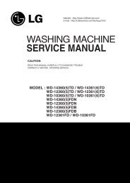
TUBE<br />
LOKRING<br />
LOKRING<br />
JOINT<br />
Figure 23. LOKRING<br />
ASSEMBLY JAWS<br />
BOLT<br />
TOOL<br />
Figure 24. LOKRING TOOL<br />
- 17 -
SERVICING PRECAUTIONS<br />
Features of refrigerant (R600a)<br />
• Achromatic and odor less gas.<br />
• Flammable gas and the ignition (explosion) at 494°C.<br />
• Upper/lower explosion limit: 1.8%~8.4%/Vol.<br />
Features of the R600a refrigerator<br />
• Charging of 60% refrigerant compared with a R134a model<br />
• The suction pressure is below 1bar (abs) during the operation.<br />
• Because of its low suction pressure, the external air may<br />
flow in the cycle system when the refrigerant leak, and it<br />
causes malfunction in the compressor.<br />
• The displacement of compressor using R600a must be at<br />
least 1.7 times larger than that of R134a.<br />
• Any type of dryer is applicable (XH-5, 7, 9).<br />
• The EVAPORATOR or any other cycle part that has<br />
welding joint is hidden in the foam. (If not hidden inside,<br />
the whole electric parts must be tested with the<br />
LEAK<strong>AG</strong>E TEST according to the IEC Standard.)<br />
• The compressor has label of the refrigerant R600a.<br />
• Only the SVC man must have an access to the system.<br />
Installation place<br />
• Must be well ventilated.<br />
• Must be 20 m 3 or larger.<br />
• Must be no-smoking area.<br />
• No ignitable factors must be present.<br />
Utilities<br />
• Refrigerant cylinder (MAX NET 300g)<br />
• Manometer<br />
• Vacuum pump (600L/min)<br />
• Piercing Clamp<br />
• Quick coupler<br />
• Hoses (5m-1EA, 1m-3EA)<br />
• LOKRING<br />
• Portable Leakage detector (3g/year↓)<br />
• Nitrogen cylinder (for leakage test)<br />
• Concentration gauge<br />
Make sure before Servicing<br />
• Refrigerant<br />
Confirm the refrigerant by checking Name Plate and the label<br />
on the compressor, after opening the COVER ASSY,<br />
BACK-M/C.<br />
• If the refrigerant is R600a, you must not weld or apply a<br />
heat source.<br />
Air Recharging in Compressor<br />
Before refilling the refrigerant, you must perform the test according<br />
to Chapter 5 (TROUBLESHOOTING CHART). When the defects<br />
are found, you must discharge the residual refrigerant (R600a) in<br />
the outdoor. For discharging the refrigerant R600a, break the<br />
narrow portion of tube extension by hand or with a pipe cutter as<br />
shown in Figure 1. Leave it for 30min in outside to stabilize the<br />
pressure with ambient. Then, check the pressure by piercing the<br />
dryer part with piercing pliers. If the refrigerant is not completely<br />
discharged, let the refrigerator alone for more 30min in outside.<br />
POINT TO BE<br />
BROKEN<br />
SERVICE TUBE<br />
EXTENSION<br />
CHARGE TUBE<br />
EXTENSION<br />
SCHRADER VALVE<br />
(ONE-WAY VALVE)<br />
LOKRING<br />
Figure 1 Figure 2<br />
Attach the service tube installed with a Schrader valve (one-way<br />
valve) by using the LOKRING (Figure 2). Then, connect the<br />
Schrader valve (one-way valve) to the pump that is connected to<br />
the discharging hose leading to the outside. When discharging the<br />
residual refrigerant, repeat 3 cycle that includes 3min of the pump<br />
running->pump off->30sec of the compressor running.<br />
- 3 -<br />
After the refrigerant (R600a) is completely discharged, repair any<br />
defective parts and replace the dryer. At any case you must use the<br />
LOKRING for connecting or replacing any part in the cycle (No Fire,<br />
No Welding). Connect the Schrader valve to pump with the coupler.<br />
And then turn the pump on for vacuum state (Figure 3). Let the<br />
pump run until the low-pressure gauge indicates the vacuum (gauge<br />
pressure 0, absolute pressure -1atm or -760mmHg). Recommended<br />
vacuum time is 30 min. Charge the N2 gas in order to check for<br />
leakage from welding points and the LOKRING. If leakages are<br />
found, repair the defects and repeat the vacuum process.<br />
Figure 3<br />
TO THE<br />
VACUUM<br />
PUMP<br />
PRESSURE<br />
GAUGE<br />
After the system is completely vacuumed, fill it with the refrigerant<br />
R600a up to what has been specified at your refrigerator Name<br />
Plate. The amount of refrigerant (R600a) must be precisely<br />
measured within the error of ±2g by an electron scale (Figure 4).<br />
If you use the manifold connected with both the refrigerant<br />
(R600a) cylinder and the vacuum pump simultaneously,<br />
make sure the pump valve is closed (Figure 5).<br />
Figure 4<br />
REFRIGERANT<br />
(R600a)<br />
COUPLE<br />
THROTTLE<br />
VALVE<br />
FILLING OR<br />
CHARGE TUBE<br />
TO THE<br />
REFRIGERATION<br />
SYSTEM<br />
TO THE VACUUM PUMP<br />
CHARGING HOSE<br />
WEIGH SCALE<br />
VALVE TO BE OPENED<br />
WHEN REFILLING<br />
TO THE CHARGE<br />
CYLINDER<br />
VALVE TO BE CLOSED<br />
AFTER VACUUM<br />
Figure 5<br />
Connect the charging hose (that is connected to the refrigerant<br />
(R600a) cylinder) to the Schrader valve installed on the service<br />
tube. Then, charge the refrigerant (R600a) by controlling the<br />
Throttle valve. When you do so, do not fully open the Throttle valve<br />
because it may make damage to the compressor. Gradually charge<br />
the refrigerant (R600a) by changing open and close the Throttle<br />
Valve (5g at each time). The charging hose must use a one-way<br />
valve to prevent the refrigerant refluence. Close the Schrader valve<br />
cap after the refrigerant (R600a) is completely recharged.<br />
After you completely recharge the refrigerant (R600a), perform the<br />
leakage test by using a portable leakage detector or soapy water.<br />
Test the low pressure (suction) parts in compressor off time and<br />
high pressure parts in compressor on time. If the leakages are<br />
found, restart from the refrigerant (R600a) discharging process and<br />
repairs defects of leaks.<br />
After the leakage test, check the temperature of each parts of the<br />
cycle. Check with hands if the CONDENSER and the case (HOT-<br />
LINE pipe) that is contacted to the door gasket are warm. Confirm<br />
that frost is uniform distributed on the surface of the EVAPORATOR.
SPECIFICATIONS<br />
1.Ref. No: GR-<strong>399</strong><br />
ITEMS<br />
SPECIFICATIONS<br />
ITEMS<br />
SPECIFICATIONS<br />
DIMENSIONS (mm)<br />
595(W)X626(D)X1880(H)<br />
Transparent Shelf(3 EA)<br />
NET WEIGHT (kg) 74<br />
REFRIGERATOR<br />
Vegetable Container(2 EA)<br />
COOLING SYSTEM<br />
Fan Cooling<br />
COMPARTMENT<br />
Vegetable Container Cover(1 EA)<br />
TEMPERATURE<br />
CONTROL<br />
REFRIGERATOR<br />
FREEZER<br />
Knob Dial<br />
Button<br />
Chilled Container(1 EA)*<br />
Dairy Pocket Cover(1 EA)<br />
DEFROSTING SYSTEM<br />
Full Automatic<br />
Heater Defrost<br />
DOOR POCKET<br />
Egg Tray(2 EA)<br />
Little Pocket(5 EA)<br />
DOOR FINISH<br />
Pre-Coated Metal<br />
or Vinyl Coated Metal<br />
Bottle Pocket(1 EA)<br />
OUT CASE<br />
Painted Steel Sheet<br />
FREEZER<br />
Tray Drawer(4 EA)<br />
INNER CASE<br />
ABS<br />
COMPARTMENT<br />
Ice Tray(1 EA)<br />
INSULATION<br />
Polyurethane Foam<br />
COMPRESSOR<br />
PTC Starting Type<br />
DEFROSTING DEVICE<br />
Heater, Sheath & Heater, Cord-L<br />
EVAPORATOR<br />
Fin Tube Type<br />
REFRIGERANT<br />
R600a(54g)<br />
CONDENSER<br />
Side & Wire Condenser<br />
LUBRICATION OIL<br />
FREOL S10(280 cc)<br />
* Optional Parts<br />
2.Ref. No: GR-<strong>359</strong><br />
ITEMS<br />
SPECIFICATIONS<br />
ITEMS<br />
SPECIFICATIONS<br />
DIMENSIONS (mm)<br />
595(W)X626(D)X1710(H)<br />
Transparent Shelf(2 EA)<br />
NET WEIGHT (kg) 69<br />
REFRIGERATOR<br />
Vegetable Container(2 EA)<br />
COOLING SYSTEM<br />
Fan Cooling<br />
COMPARTMENT<br />
Vegetable Container Cover(1 EA)<br />
TEMPERATURE<br />
CONTROL<br />
REFRIGERATOR<br />
FREEZER<br />
Knob Dial<br />
Button<br />
Chilled Container(1 EA)*<br />
Dairy Pocket Cover(1 EA)<br />
DEFROSTING SYSTEM<br />
Full Automatic<br />
Heater Defrost<br />
DOOR POCKET<br />
Egg Tray(1 EA)<br />
Little Pocket(3 EA)<br />
DOOR FINISH<br />
Pre-Coated Metal<br />
or Vinyl Coated Metal<br />
Bottle Pocket(1 EA)<br />
OUT CASE<br />
Painted Steel Sheet<br />
FREEZER<br />
Tray Drawer(4 EA)<br />
INNER CASE<br />
ABS<br />
COMPARTMENT<br />
Ice Tray(1 EA)<br />
INSULATION<br />
Polyurethane Foam<br />
COMPRESSOR<br />
PTC Starting Type<br />
DEFROSTING DEVICE<br />
Heater, Sheath & Heater, Cord-L<br />
EVAPORATOR<br />
Fin Tube Type<br />
REFRIGERANT<br />
R600a(54g)<br />
CONDENSER<br />
Side & Wire Condenser<br />
LUBRICATION OIL<br />
FREOL S10(280 cc)<br />
* Optional Parts<br />
- 4 -
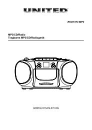
PARTS IDENTIFICATION<br />
Freezer Temperature<br />
Control<br />
Egg Tray(1 or 2)<br />
Removable<br />
Glass Shelf(2 or 3)<br />
Lamp<br />
Rotatable<br />
Door Basket<br />
(3 or 5)<br />
Multi-air Flow Duct<br />
Fresh Meat Keeper<br />
(Optional)<br />
Refrigerator<br />
Temperature Control<br />
Vegetable Drawer<br />
Used to keep fruits<br />
and vegetables, etc.<br />
fresh and crisp.<br />
Ice Cube Tray<br />
Utility Corner<br />
(movable)<br />
Bottle Holder<br />
2L Bottle<br />
Door Basket<br />
Freezer<br />
Compartment<br />
Removable<br />
Plinth<br />
Leveling Screw<br />
NOTE : This is a basic model. The shape of refrigerator is subject to change.<br />
- 5 -
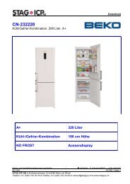
REPLACEMENT OF DOOR OPENING TYPE<br />
1. PRECAUTION<br />
1) Before reversing the door, first of all, you should take<br />
out food and accessories like shelves or trays which are<br />
not fixed in the refrigerator.<br />
2) Use Torque Wrench or Spanner to fix or remove the bolt.<br />
3) Don't lay the refrigerator down in working with it, it will<br />
cause to get out of order.<br />
4) Be careful not to drop the door in disassembling or<br />
assembling the freezer or the refrigerator door.<br />
2. HOW TO REVERSE THE DOORS<br />
1) Seperate screw ➋ and remove lower cover ➊ and move<br />
cap lower cover ➌. And, seperate screw ➍, lower hinge<br />
➎, and remove pin ➏. Separating the freezer door in<br />
opening, and more the position the cap ➐.<br />
21<br />
Move the position of bracket door ➑ and screw ➒.<br />
2) Separating screw 10 and remove the center hinge 11<br />
and the refrigerator door 12 . Move the position of cap 13 .<br />
Move the position of bracket door 16 and screw 17 .<br />
3) Move the position of upper hinge pin 14 , and cap 15 .<br />
Assemble the refrigerator door 12 . Assemble center<br />
hinge 11 and bolt 10 . Assemble freezer door 21 .<br />
Assemble the lower hinge ➎, bolt ➍ and lower cover ➊.<br />
14<br />
7<br />
6<br />
5<br />
3<br />
21<br />
8<br />
4<br />
15<br />
9<br />
1<br />
2<br />
12<br />
12<br />
11<br />
10<br />
13<br />
11<br />
10<br />
16<br />
17<br />
21<br />
5<br />
4<br />
1<br />
2<br />
- 6 -
DISASSEMBLY<br />
1 DOOR<br />
● Freezer Door<br />
1) Loosen 2 screws and pull the Lower Cover.<br />
2) Loosen hexagonal bolts fixing the lower hinge to the<br />
body to remove the freezer door only.<br />
2 DOOR SWITCH<br />
1) Loosen four screws in upper part and disconnect top<br />
cover.<br />
2) Disconnect Lead Wire from switch.<br />
3) Disengage hook behind the switch by pressing it with<br />
hands.<br />
Lower Hinge<br />
Bolt<br />
Figure 6<br />
3) Pull out the Door Gasket to remover from the<br />
Door Foam Assy, F.<br />
GASKET<br />
Figure 9<br />
3 REFRIGERATOR ROOM LAMP<br />
1) Remove the Cover Lamp, R by pulling with a '–' type<br />
driver.<br />
2) Remove the Lamp by turning.<br />
Figure 7<br />
● Refrigerator Door<br />
1) Loosen hexagonal bolts fixing the center hinge(Hinge,C)<br />
to the body to remove the refrigerator door only.<br />
Figure 10<br />
3) After removing the lamp, you must check<br />
the O-RING, which is made by rubber and prevent<br />
electric spark, in the socket.<br />
Hinge, C<br />
Bolt<br />
Figure 8<br />
2) Pull out the Door Gasket to remove from the<br />
Door Foam Assy, R.<br />
- 7 -
4 FAN AND FAN MOTOR<br />
1) Remove freezer drawers.<br />
2) Remove two cap, screws and loosen two screws in Grille Fan.<br />
3) Pull out the Grille Fan and Shroud, F.<br />
4) Disconnect the housing of lead wire.<br />
5) Separate the Fan Assy.<br />
6) Losse 2 screw fixed to the Bracket.<br />
7) Pull out Shroud, F remove the Fan Motor Assy.<br />
8) Separate the Motor Bracket and Rubber.<br />
6 DAMPER CONTROL<br />
1) Remove the Cover Lamp, R and loosen 2 screw.<br />
2) Pull the Control Box, R and separate the lead wire<br />
housing.<br />
3) Remove the Cover Lamp, R.<br />
4) Separate the Insulation Multi Duct and Control Box, R.<br />
5) Disassemble the Knob.<br />
6) Separate the Damper Control and Control Box, R.<br />
7) Separate the Damper Control and Resistor.<br />
8) Disconnect the lead wire.<br />
SHROUD<br />
FAN MOTOR<br />
REFRIGERATOR ROOM LAMP<br />
GUIDE FAN<br />
FAN<br />
GRILLE<br />
Figure 11<br />
5 DEFROST CONTROL ASSY<br />
Defrost Control Assy consists of Thermistor and Fuse, Melting.<br />
Thermistor functions to defrost automatically and it is attached to<br />
metal side of the Evaporator and senses temperature.<br />
Fuse, Melting is a kind of safety device for preventing overheating<br />
of the Heater when defrosting.<br />
At the temperature of 72°C, it stops the emission of heat from the<br />
Heater.<br />
1) Pull out the Shroud, F after removing the Grille.<br />
2) Separate the connector connected with the Defrost Control<br />
Assy and replace new one.<br />
Figure 13<br />
7 HEATER, SHEATH & HEATER, CORD-L<br />
In this refrigerator, Heater, Sheath & Heater, Cord-L are<br />
used for defrosting heater. During heating, the temperature<br />
of heater rises about 300~350°C. Therefore, be careful not<br />
to burn while servicing.<br />
1) After removing the Grille and Shroud, separate the<br />
Heater, Sheath by disconnecting the connectors.<br />
2) Exchanged Heater, Sheath and connected the housing.<br />
Thermister<br />
Heater, Cord-L<br />
Fuse, Melting<br />
Figure 12<br />
Heater, Sheath<br />
Figure 14<br />
3) If the Heater, Cord-L is defected, disconnect the<br />
connectors, and separate the Heater, Cord-L with<br />
Long Nose.<br />
4) Replace and assembly the Heater, Cord-L and connect<br />
the connectors.<br />
- 8 -
ADJUSTMENT<br />
1 COMPRESSOR<br />
1) Role<br />
The compressor intakes low temperature and low pressure<br />
gas evaporated from Evaporator of the Refrigerator, and<br />
condenses this gas to high temperature and high pressure<br />
gas, and then plays delivering role to Condenser.<br />
2) Composition<br />
The Compressor is Composed of Compressor Apparatus<br />
compressing gas, Compressor Motor moving Compressor<br />
Apparatus and Case protecting Compressor Apparatus<br />
and Motor. There is Relay Assy (one set of PTC-Starter<br />
and Over Load Protector (OLP)) in Compressor. On the<br />
other hand, because the Compressor consists of<br />
1/1000mm processing precision components and is sealed<br />
after production in absence of dust or humidity, deal and<br />
repair with care.<br />
3) Note for Usage<br />
(1) Be careful not to allow over-voltage and over-current.<br />
(2) No Strike<br />
If applying forcible power or strike (dropping or careless<br />
dealing), poor operation and noise may occur.<br />
(3) Use proper electric components appropriate to the<br />
Compressor.<br />
(4) Note to Keep Compressor.<br />
If Compressor gets wet in the rain and rust in the pin of<br />
Hermetic Terminal, the result may be poor operation<br />
and poor contact may cause.<br />
(5) Be careful that dust, humidity, and flux welding don't<br />
inflow in the Compressor inside in replacing the<br />
Compressor. Dust, humidity, and flux due to welding<br />
which inflows to Cylinder may cause lockage and noise.<br />
2 PTC-STARTER<br />
1) Composition of PTC-Starter<br />
(1) PTC (Positive Temperature Coefficient) is a no-contact<br />
semiconductor starting device which uses ceramic<br />
material and this material consists of BaTiO3.<br />
(2) The higher the temperature is, the higher becomes the<br />
resistance value. These features are used as starting<br />
device for the Motor.<br />
2) Role of PTC-Starter<br />
(1) PTC is attached to Hermetic Compressor used for<br />
Refrigerator, Show Case and starts Motor.<br />
(2) Compressor for household refrigerator applies to<br />
single-phase induction Motor.<br />
For normal operation of the single-phase induction<br />
motor, in the starting operation flows in both main coil<br />
and sub-coil. After the starting is over, the current in<br />
subcoil is cut off. The proper features of PTC play all<br />
the above roles. So, PTC is used as a motor starting<br />
device.<br />
3) PTC-Applied Circuit Dia<strong>gr</strong>am<br />
● According to Starting Method for the Motor<br />
OVERLOAD<br />
PROTECTOR(O.L.P)<br />
PTC<br />
S<br />
3 M<br />
COMPRESSOR<br />
MOTOR<br />
M<br />
S M<br />
PTC STARTER<br />
HERMETIC<br />
RSIR<br />
TERMINAL<br />
RELAY ASSY Figure 19<br />
4) Motor Restarting and PTC Cooling<br />
(1) For restarting after power off during normal<br />
Compressor Motor operation, plug the power cord after<br />
5 min. for pressure balance of Refrigerating Cycle and<br />
PTC cooling.<br />
(2) During normal operation of the Compressor Motor, PTC<br />
elements generate heat continuously. Therefore,<br />
if PTC isn't cooled for a while after the power has been<br />
shut off, Motor can't operate again.<br />
5) Relation of PTC-Starter and OLP<br />
(1) If the power is off during operation of Compressor and<br />
the power is on before the PTC is cooled, (instant shutoff<br />
within 2 min. or reconnect a power plug due to<br />
misconnecting), the PTC isn't cooled and a resistance<br />
value <strong>gr</strong>ows. As a result, current can't flow to the subcoil<br />
and the Motor can't operate and the OLP operates<br />
by flowing over current in only in the main-coil.<br />
(2) While the OLP repeats on and off operation about 3-5<br />
times, PTC is cooled and Compressor Motor performs<br />
normal operation.<br />
If OLP doesn't operate when PTC is not cooled,<br />
Compressor Motor is worn away and causes circuitshort<br />
and fire. Therefore, use a properly fixed OLP<br />
without fail.<br />
6) Note to Use PTC-Starter<br />
(1) Be careful not to allow over-voltage and over-current.<br />
(2) No Strike<br />
Don't apply a forcible power or strike.<br />
(3) Keep apart from any liquid.<br />
If liquid such as oil or water away enter the PTC,<br />
PTC materials it may break due to insulation breakdown<br />
of the material itself.<br />
(4) Don't change PTC at your convenience.<br />
Don't disassemble PTC and mold. If the exterior to the<br />
PTC-starter is damaged, resistance value is altered and<br />
it may cause poor starting of the compressor motor may<br />
cause.<br />
(5) Use a properly fixed PTC.<br />
S<br />
C<br />
- 9 -
CIRCUIT DI<strong>AG</strong>RAM<br />
NOTE : 1. This is a basic dia<strong>gr</strong>am and specifications vary in different localities.<br />
- 10 -
TROUBLESHOOTING (Mechanical Part)<br />
1 COMPRESSOR AND ELECTRIC COMPONENTS<br />
1<br />
Power<br />
Source.<br />
Remove the Relay Assy<br />
from the Compressor<br />
and measure the voltage<br />
between Terminal C of<br />
Compressor and<br />
Terminals M or S of<br />
Relay Assy<br />
(Rating Voltage<br />
±10%)?<br />
YES<br />
2<br />
No Voltage.<br />
5<br />
Applied voltage isn't<br />
in the range of Rating<br />
Voltage ±10%.<br />
Advise the customer<br />
to use a regular<br />
Trans.<br />
5<br />
2<br />
Check the<br />
resistance of<br />
Motor<br />
Compressor.<br />
Check the resistance<br />
among M-C, S-C and<br />
M-S in Motor<br />
Compressor.<br />
NO<br />
YES<br />
Replace Compressor.<br />
3<br />
4<br />
3<br />
5<br />
3<br />
Check the<br />
resistance of<br />
PTC-Starter.<br />
Check the resistance of<br />
two terminals in PTC-<br />
Starter.<br />
YES<br />
NO<br />
Replace<br />
Relay Assy<br />
4<br />
5<br />
4<br />
Check OLP.<br />
Check if applying<br />
a regular OLP.<br />
YES<br />
OLP works within<br />
30 sec. in forcible<br />
OLP operation by<br />
turning instant power<br />
on and off.<br />
NO<br />
YES<br />
Replace<br />
Relay Assy<br />
5<br />
5<br />
Check<br />
starting state.<br />
Measure minimum<br />
starting voltage after 5<br />
min. for balancing cycle<br />
pressure and cooling the<br />
PTC.<br />
Components start in<br />
the voltage of Rating<br />
Voltage ±10% below.<br />
YES<br />
NO<br />
O.K.<br />
1<br />
- 11 -
2 RELAY ASSY (PTC AND OLP)<br />
Normal operation of<br />
Compressor is<br />
impossible or poor.<br />
Separate the Relay Assy<br />
from Compressor and<br />
measure the resistance<br />
between M and S with a<br />
Tester or Whistone Bridge.<br />
(Figure 21)<br />
Observation value is<br />
220V/50Hz : 22Ω±30%<br />
115V/60Hz : 6.8Ω±30%<br />
240V/50Hz : 33Ω±30%<br />
127, 220V/60Hz :<br />
22Ω±30%<br />
Check another<br />
electric<br />
components.<br />
The resistance value is 0<br />
or serveral hundreds Ω.<br />
Replace<br />
Relay Assy.<br />
The value is ∞.<br />
Separate the Relay Assy<br />
from the Compressor and<br />
check the resistance value<br />
between two terminals of<br />
OLP with a Tester.<br />
(Figure 22)<br />
YES<br />
NO<br />
Check another<br />
electric components.<br />
Replace Relay Assy.<br />
T<br />
L<br />
2<br />
N<br />
C<br />
C<br />
M<br />
S<br />
M<br />
S<br />
3 2<br />
Figure 21 Figure 22<br />
- 12 -
3 ANOTHER ELECTRIC COMPONENTS<br />
▼ Cooling is impossible<br />
Compressor<br />
doesn't run.<br />
Check if current flows to<br />
the following<br />
components.<br />
Cause.<br />
a. Thermistor<br />
Poor contacting.<br />
b. Starting devices<br />
c. OLP<br />
d. Compressor coil<br />
e. Circuit Parts<br />
Shorted or broken.<br />
Poor contacting<br />
or shorted.<br />
Coil shorted.<br />
Poor contacting<br />
or shorted.<br />
Replace<br />
each component.<br />
Running state of<br />
Compressor is poor.<br />
Check a starting<br />
voltage.<br />
Low voltage.<br />
Raise the voltage.<br />
Check if current flows<br />
to starting devices.<br />
Poor contacting<br />
and broken.<br />
Replace<br />
each component.<br />
Check current flowing<br />
in sub-coil of<br />
Compressor.<br />
Shorted.<br />
Check capacity of OLP.<br />
Lack of capacity.<br />
The items described<br />
above are normal.<br />
Coil of motor<br />
Compressor.<br />
Replace<br />
the compressor.<br />
▼ Cooling ability is poor<br />
Fan motor<br />
doesn't run.<br />
Check current flowing<br />
in SWITCH, DOOR.<br />
Check current flowing in the<br />
MOTOR[MECH], FAN.<br />
Poor contacting.<br />
Coil is shorted.<br />
Replace<br />
each component.<br />
Much frost are sticked<br />
to the EVAPORATOR.<br />
Check current flowing<br />
of the following<br />
components.<br />
• THERMISTOR<br />
• FUSE, MELTING<br />
Shorted.<br />
Replace<br />
each component.<br />
Check current flowing<br />
of the following<br />
components.<br />
• HEATER, SHEATH<br />
• HEATER, CORD-L<br />
Defect on<br />
Heater, Cord-L<br />
Replace<br />
the Heater, Sheath<br />
Replace<br />
the Heater, Cord-L<br />
- 13 -
4 SERVICE DI<strong>AG</strong>NOSIS CHART<br />
COMPLAINT POINTS TO BE CHECKED REMEDY<br />
Cooling is • Is the power cord unplugged from the outlet? • Plug to the outlet.<br />
impossible. • Check if the power switch is set to OFF. • Set the switch to ON.<br />
• Check if the fuse of power switch is shorted.<br />
• Replace a regular fuse.<br />
• Measure the voltage of power outlet.<br />
• If voltage is low, wire newly.<br />
Cooling ability • Check if the set is placed close to wall. • Place the set with the space of about 10cm.<br />
is poor. • Check if the set is placed close to stove, gas • Place the set apart from these heat<br />
• cooker and direct rays.<br />
• appliances.<br />
• Is the ambient temperature high or<br />
• Make the ambient temperature below.<br />
• the room door closed?<br />
• Check if put in is hot.<br />
• Put in foods after cooled down.<br />
• Did you open the door of the set too often<br />
• Don't open the door too often and close<br />
• or check if the door is closed up?<br />
• it firmly.<br />
• Check if the Damper Control is set to "cold-position". • Set the control to mid-position.<br />
Foods in the • Is foods placed in cooling air outlet? • Place foods in high temperature section.<br />
Refrigerator<br />
• (Front Part)<br />
are frozen. • Check if the control is set to "cold-position". • Set the control to "mid-position".<br />
• Is the ambient temperature below 5°C?<br />
• Set the control to "warm-position".<br />
Dew or ice • Is liquid food stored? • Seal up liquid foods with wrap.<br />
forms in the • Check if put in is hot. • Put in foods after cooled down.<br />
chamber of • Did you open the door of the set too • Don't open the door too often and close<br />
the set. • often or check if the door is closed up. • it firmly.<br />
Dew forms • Check if ambient temperature and humidity • Wipe dew with a dry cloth. This occurrence<br />
in the Exterior Case. of surroumcling air are high. • is solved naturally in low temperature and humidity.<br />
• Is there gap in the door packed?<br />
• Fill up the gap.<br />
Abnormal • Are the set positioned in a firm and even place? • Adjust the Adjust Screw, and position<br />
noise generates.<br />
• in the firm place.<br />
• Are any unnecessary objects set<br />
• Remove the objects.<br />
• in the back side of the set?<br />
• Check if the Tray Drip is not firmly fixed.<br />
• Fix it firmly on the original position.<br />
• Check if the cover of mechanical room<br />
• Place the cover at the original position.<br />
• in below and front side is taken out.<br />
To close the door • Check if the door packing is dirty • Clean the door packing.<br />
is not handy.<br />
• with filth such as juice.<br />
• Is the set positioned in a firm and even place? • Position in the firm place and adjust the<br />
• Adjust Screw.<br />
• Is too much food putted in the set?<br />
• Keep foods not to reach the door.<br />
Ice and foods • Check if the inside of the set is dirty. • Clean the inside of the set.<br />
smell unpleasant. • Did you keep smelly foods without wrapping? • Wrap smelly foods.<br />
• It smells of plastic.<br />
• The new products smells of plastic, but it is<br />
• eliminated after 1-2 weeks.<br />
● In addition to the items described left, refer to the followings to solve the complaint.<br />
Check if dew forms in<br />
the Freezer.<br />
Defrosting<br />
is poor.<br />
Replace the<br />
Components of<br />
defrosting circuit.<br />
Check Refrigerating<br />
Cycle.<br />
The cycle<br />
is faulty.<br />
Repair the cycle.<br />
Check the<br />
Damper Control<br />
The operation of<br />
the Damper<br />
Control is poor.<br />
Replace the<br />
Damper Control<br />
- 14 -
5 REFRIGERATING CYCLE<br />
▼ Troubleshooting Chart<br />
CAUSE<br />
STATE OF<br />
THE SET<br />
STATE OF THE<br />
EVAPORATOR<br />
TEMPERATURE<br />
OF THE<br />
COMPRESSOR<br />
REMARKS<br />
LEAK<strong>AG</strong>E CLOGGED BY DUST<br />
DEFECTIVE<br />
COMPRESSION<br />
PARTIAL Freezer room and Low flowing sound of A little high • A little Refrigerant<br />
LEAK<strong>AG</strong>E Refrigerator Refrigerant is heard and more than • discharges.<br />
don't cool frost forms in inlet only ambient • Normal cooling is possible<br />
normally. temperature. • when injecting of Refrigerant<br />
• the regular amount.<br />
WHOLE Freezer room and Flowing sound of Refrigerant Equal to ambient • No discharging of Refrigerant.<br />
LEAK<strong>AG</strong>E Refrigerator is not heard and frost isn't temperature. • Normal cooling is possible<br />
don't cool formed. • when injecting of Refrigerant<br />
normally.<br />
• the regular amount.<br />
PARTIAL Freeze room and Flowing sound of Refrigerant A little high • Normal discharging of<br />
CLOG Refrigerator is heard and frost forms more than • refrigerant.<br />
don't cool in inlet only. ambient • The capillary tube is faulty.<br />
normally.<br />
temperature.<br />
WHOLE Freezer room and Flowing sound of Refrigerant Equal to ambient • Normal discharging of<br />
CLOG Refrigerator is not heard and frost isn't temperature. • Refrigerant.<br />
don't cool. formed.<br />
MOISTURE Cooling operation Flowing sound of Refrigerant Low than • Cooling operation restarts<br />
CLOG stops periodically. is not heard and frost melts. ambient • when heating the inlet of<br />
temperature • capillary tube.<br />
COMP- Freezer and Low flowing sound of A little high • The pressure of high<br />
RESSION Refrigerator Refrigerant is heard and than ambient • pressure part in<br />
don't cool. frost forms in inlet only. temperature. • compressor is low.<br />
NO COMP- No compressing Flowing sound of Refrigerant Equal to ambient • No pressure of high pressure<br />
RESSION operation. is not heard and no frost. temperature. • part in the compressor.<br />
▼ Leakage Detection<br />
● Observe discharging point of refrigerant which may be in the oil discharging part in the compressor and hole of evaporator.<br />
Whether Compressor<br />
runs or not.<br />
Frost formed normally<br />
YES<br />
Normal amount<br />
Whether frost<br />
forms or not in<br />
Evaporator.<br />
No frost<br />
or forms<br />
in inlet only<br />
Whether oil<br />
leaks or not.<br />
Observe the discharged<br />
amount of Refrigerant.<br />
No or much amount<br />
YES<br />
Moisture Clog.<br />
Faulty<br />
Compressor.<br />
Inject Refrigerant to Compressor<br />
and check cooling operation.<br />
Check Compressor<br />
Clogged by dust.<br />
Gas leakage.<br />
Frost formed normally<br />
(Check the leakage point)<br />
- 15 -
▼ General Control of Refrigerating Cycle<br />
NO. ITEMS CONTENTS AND SPECIFICATIONS REMARKS<br />
1<br />
2<br />
3<br />
4<br />
5<br />
WELDING (1) H 30<br />
ROD (1) • Chemical In<strong>gr</strong>edients • Recommend H34 containing 34% Ag in the<br />
(1) • Ag: 30%, Cu: 27%, Zn: 23%, Cd: 20% • Service Center.<br />
(1) • Brazing Temperature: 710~840°C<br />
(2) Bcup-2<br />
(1) • Chemical In<strong>gr</strong>edients<br />
(1) • Cu: About 93%<br />
(1) • P: 6.8~7.5%<br />
(1) • The rest: within 0.2%<br />
(1) • Brazing Temperature: 735~840°C<br />
FLUX (1) • In<strong>gr</strong>edients and how to make • Make amount for only day. (1)<br />
(1) ••Borax 30% • Holding period: 1 day<br />
(1) ••Borax 35% • Close the cover of container to prevent dust<br />
(1) • Fluoridation kalium: 35% • putting in the FLUX.<br />
(1) • Water: 4% • Keep it in a stainless steel container.<br />
(1) • Mix the above in<strong>gr</strong>edients and boil until<br />
(1) • they are transformed into liquid.<br />
LOKRING (1) Both of the tube is inserted up to the stop. • For a hermetically sealed metal/metal<br />
(Figure 23,24) (2) Both of the LOKRING is pushed up to the stop connection, the tube ends have to be clean.<br />
(3) The bending point is not too close to the • LOKPREP is distributed all of out-surface of<br />
joint ending.<br />
• the tube ends.<br />
(4) During the assembly it is important that<br />
both ends remain completely within the<br />
joint.<br />
DRIER (1) Assemble the drier within 30min. • Don't keep the drier in a outdoors because<br />
ASM (1) after unpacking. • humidity damages to it.<br />
(2) Keep the unpacked drier at the temperature<br />
of 80~100°C.<br />
VACUUM (1) When measuring with pirant Vacuum • Apply M/C Vacuum Gauge without fail.<br />
(1 )gauge the charging M/C, vacuum • Perform vacuum operation until a proper<br />
(1 )de<strong>gr</strong>ee is within 1 Torr. • vacuum de<strong>gr</strong>ee is built up.<br />
(2) If the vacuum de<strong>gr</strong>ee of the cycle inside is • If a proper vacuum de<strong>gr</strong>ee isn't built up,•<br />
(2) 10 Torr. below for low pressure and 20 Torr. • check the leakage from<br />
(2) for high pressure, it says no vacuum • the Cycle Pipe line part and<br />
(2) leakage state. • Quick Coupler Connecting part.<br />
(3) Vacuum de<strong>gr</strong>ee of vacuum pump must be<br />
(3) 0.05 Torr. below after 5 min.<br />
(4) Vacuum de<strong>gr</strong>ee must be same to the<br />
value described item (2) above for more than<br />
20 min.<br />
6<br />
DRY AND<br />
AIR<br />
NITROGEN<br />
GAS<br />
(1) The pressure of dry air must be more<br />
han 12~16kg/cm 2<br />
(2) Temperature must be more than<br />
-20~-70°C.<br />
(3) Keep the pressure at 12~6kg/cm 2 also<br />
when substituting dry air for Nitrogen Gas.<br />
7<br />
NIPPLE (1) Check if gas leaks with soapy water. • Check if gas leaks from joint of the<br />
AND (2) Replace Quick Coupler in case of leakage. • Coupler.<br />
COUPLER<br />
8<br />
PIPE<br />
(1)• Put all Joint Pipes in a clean box and<br />
(1)• cover tightly with the lid so that dust or<br />
(1)• humidity is not inserted.<br />
- 16 -
MICOM FUNCTION & PCB CIRCUIT EXPLANATION<br />
This description is made for GR-349, 389SQ. Please refer to overall PCB circuits for other models.<br />
1 FUNCTION EXPOSITION<br />
1) FUNCTION<br />
(1) The refrigerator starts from optimum condition when electric power is first on. But the operation condition changes "Mid"<br />
➝ "Mid/Max" ➝ "Max" ➝ "Min" ➝ "Min/Mid" ➝ "Mid" whenever pressing the FREEZE TEMP button.<br />
(2) It returns to "Mid" conditions if power off and on again.<br />
VACATION FREEZE TEMP QUICK FREEZE<br />
NOTCH<br />
Min<br />
Min/<br />
Mid<br />
Mid<br />
Mid/<br />
Max<br />
Max<br />
TEMP(˚C)<br />
-15 -16.5 -18 -19.5<br />
-22<br />
ROOM<br />
FREEZER<br />
2) QUICK FREEZER<br />
(1) Function to raise the freezing speed by operating the COMP successively. As pressing the QUICK FREEZE button, the<br />
QUICK FREEZE LED is displayed. Then after 3 hours' successive operation of COMP, the QUICK FREEZING function<br />
will be released.<br />
(2) Defrosting During the QUICK FREEZING operates as follow.<br />
When the QUICK FREEZING time is below 90 minutes, defrost and then operate the QUICK FREEZING for the<br />
remaining time. When the QUICK FREEZING time is over 90 minutes, defrost and then operate the QUICK FREEZING<br />
for 2 hours<br />
(3) If QUICK FREEZE button is pressed during defrosting, the QUICK FREEZE LED is lit up. But the QUICK FREEZING<br />
operates for 3 hours after 7 minutes from the end of defrosting.<br />
(4) If VACATION button is pressed during the QUICK FREEZING, the QUICK FREEZING LED function is released.<br />
(5) If power off during the QUICK FREEZING and power on again, the QUICK FREEZING function is released.<br />
3) VACATION FUNCTION<br />
(1) Function for Energy Saving. As pressing the VACATION button, the VACATION LED is displayed and this function is<br />
operated.<br />
(2) Freezer Compartment is not kept by compressor at the notch displayed but at -13°C± differential.<br />
(3) Defrosting and Fan control is same as normal operation.<br />
(4) If QUICK FREEZE button is pressed during the VACATION FUNCTION, VACATION FUNCTION is released.<br />
(5) If power off during the VACATION FUNCTION and power on again, the VACATION FUNCTION is released.<br />
- 18 -
4) DOOR OPENING ALARM<br />
(1) When the REFRIGERATOR DOOR is opened and won't be closed after 1 minute from the its opened, BUZZER sounds<br />
to notify it.<br />
(2) At frist, BUZZER sounds three times at each intervals of 0.5 second. Then makes a 0.5 second ON/OFF alarm three<br />
times at intervals of 30 seconds.<br />
(3) If the REFRIGERATOR door closed during ALARM, it is released.<br />
REFRIGERATOR<br />
DOOR CLOSE OPEN CLOSE OPEN CLOSE<br />
three three three<br />
times times times<br />
BUZZER<br />
within<br />
1 minute<br />
1 minute 30<br />
seconds<br />
30<br />
seconds<br />
5) DISPLAY BUTTON RING<br />
(1) If display function button(FREEZE TEMP, QUICK FREEZE, VACATION) of the front of the TOP COVER is pushed,<br />
BUZZER rings with "DING~ DONG~"(See the BUZZER OPERATION CHECK)<br />
6) DEFROSTING<br />
(1) If the accumulated time for the operation of the COMPRESSOR is meet with 7 hours, the DEFROSTING HEATER is<br />
started.<br />
(2) The first defrosting is performed at 4 hours(compressor ON) later since the power is on.<br />
(3) If DEFROST SENSOR is over 7°C during DEFROSTING, end the operation of DEFROSTING with DEFROSTING<br />
HEATER paused, And after 7 minutes, the operation for the freezing is started.<br />
But, if DEFROST SENSOR is not reach to 7°C after 2 hours' operation of the defrosting heater, it represents a defrosting<br />
trouble.(See the TROUBLE REPRESENTING FUNCTION)<br />
(4) If DEFROST SENSOR is short or open, defrosting is not performed.<br />
7) ORDERLY OPERATION OF ELECTRIC PARTS<br />
To avoid NOISE and DAM<strong>AG</strong>E, the items containing an electric parts such as COMP, DEFROSTING HEATER and FAN<br />
MOTOR operate in order as follows.<br />
WHEN PLUGGED AT FIRST<br />
OPERATION STATE<br />
WHEN DEFROST SENSOR<br />
TEMPERATURE IS OVER<br />
7°C. (WHEN PURCHASING<br />
OR MOVING)<br />
WHEN DEFROST SENSOR<br />
TEMPERATURE IS BELOW<br />
7°C. (WHEN POWER<br />
FAILURE OR SERVICING)<br />
OPERATION ORDER<br />
POWER after 0.5 sec. COMP after 0.5 sec. FAN<br />
ON ON ON<br />
POWER after 0.5 sec. DEFROSTING after 10 sec. DEFROSTING<br />
ON HEATER ON HEATER ON<br />
after 0.5 sec. COMP after 0.5 sec. FAN<br />
ON<br />
ON<br />
WHEN RETURNING TO NORMAL<br />
STATE FROM TEST MODE<br />
All Elec. Parts after 7 min . COMP after 0.5 sec. FAN<br />
OFF ON ON<br />
- 19 -
8) SELF-TEST<br />
(1) Function to make service easy in case of occuring a trouble in the product.<br />
(2) When occurring a trouble, if the button is pushed, but the function could not operate.<br />
(3) If a toruble release during the representation of trouble, a refrigerator performs the normal function(RESET).<br />
(4) To represent a ERROR CODE, it use FREEZE TEMP LEDs on TOP COVER. If ERROR occurs, the other LEDs except<br />
ERROR CODE LEDs are all off.<br />
VACATION FREEZE TEMP QUICK FREEZE<br />
F1<br />
F2 F3 F4<br />
ERROR CODE LEDs<br />
O : OPERATE NORMAL<br />
:ON<br />
:OFF<br />
NO.<br />
ITEMS<br />
ERROR CODE LEDs<br />
F1 F2 F3 F4<br />
DESCRIPTION<br />
OPERATION IN TROUBLE'S OCCURRING<br />
COMP FAN DEFROST HEATER<br />
1 FREEZER FREEZER SENSOR open<br />
SENSOR abnormal<br />
or short.<br />
2 DEFROST DEFROST SENSOR open<br />
SENSOR abnormal<br />
or short.<br />
3 DEFROSTING DEFROST HEATER,<br />
FUNCTION<br />
TEMP. FUSE open or<br />
is abnormal<br />
disconnection (Displayed<br />
after at least 4 hours<br />
from the trouble's<br />
occurring.)<br />
4 RT-SENSOR NOTE 1) Room Temperature<br />
abnormal<br />
SENSOR open or short<br />
15 minutes On/<br />
15 minutes Off<br />
O<br />
O O No defrosting<br />
O<br />
O O O<br />
O O O<br />
* NOTE 1) If one second pass after pressing the QUICK FREEZE and FREEZE TEMP buttons togather in normal operation,<br />
operates as follow.<br />
RT-SENSOR<br />
If normal, LEDs on the TOP COVER is all on.<br />
If abnormal, LEDs are all on except VACATION LED.<br />
- 20 -
9) FUNCTION TEST<br />
(1) Function to check the testing function of PCB and refrigerator and to find where the trouble.<br />
(2) The test switch is on the MAIN PCB of refrigerator.<br />
TEST FUNCTION is released and RESET after MAX. 2hours regardless of TEST MODE.<br />
(3) If the buttons on TOP COVER is pushed during TEST MODE, Function is not operated and only BUZZER ring with<br />
"DING~ DONG~"<br />
(4) After the end of TEST MODE, pull out the power cord and plug it in again(RESET).<br />
(5) If a ERROR occurs during the TEST MODE, TEST FUNCTION is released and DISPLAY LEDs represent ERROR<br />
CODE.<br />
(6) If the TEST swithch is pushed during ERROR CODE, TEST FUNCTION is not operated.<br />
MODE OPERATION CONTENTS REMARKS<br />
TEST 1 Press TEST button 1. COMP OPERATES SUCCESSIVELY.<br />
once.<br />
2. FAN OPERATES SUCCESSIVELY.<br />
3. DEFROSTING HEATER OFF<br />
4. ALL DISPLAY LEDS ON.<br />
TEST 2 Press TEST button 1. COMP OFF. If DEFROST HEATER<br />
once in the state of 2. FAN OFF. is over 7°C, it returns<br />
TEST MODE 1. 3. DEFROST HEATER ON. to the NORMAL STATE.<br />
4. ALL THE DISPLAY LEDS OFF EXCEPT<br />
QUICK FREEZE AND VACATION LEDS.<br />
NORMAL Press TEST button Return to the initial condition. Comp starts<br />
STATE once in the state of (RESET) after 7 minutes.<br />
TEST MODE 2.<br />
• LED Check Function : Press the QUICK FREEZE and FREEZE TEMP buttons at the same time. After 1 sec., all the<br />
LEDs of the DISPLAY are ON simultaneously. If release the BUTTON, return to the previous<br />
condition.<br />
- 21 -
2 FUNCTION DESCRIPTION<br />
1) ELECTRIC CIRCUITS<br />
TRANS secondary side is composed of electric power circuits for RELAY driving electricity (12Vdc) and for supplying<br />
electricity to MICOM and IC (5Vdc). The voltage in each part is as follows.<br />
PARTS both ends of VA1 both ends of CM1 both ends of CM2 both ends of CE2 both ends of CC2<br />
VOLT<strong>AG</strong>E 230Vac 14Vac 17Vdc 12Vdc 5Vdc<br />
VA1 is the part to protect over voltage and noise. When more than 385V is applied, the thermal-fuse(130°C cut-off, local<br />
option) in a first part of TRANS is cut so that the elements in the secondary side of TRANS are protected.<br />
2) OSCILLATION CIRCUIT<br />
CIRCUIT for occurring CLOCK which motivates the internal local element of IC1 to transmit and receive an information and<br />
BASIC TIME for calculating time. Use a proper form for OSC 1. Because in case that SPECIFICATION is changed, the<br />
calculated time in IC1 is changed or IC1 isn't able to operate.<br />
3) RESET CIRCUIT<br />
All the internal parts of MICOM(IC1) return to the initial condition when the early power ON or apply power again in MICOM<br />
after temporary power failure. As a result, all the functions operate according to the early condition. At the early period of<br />
power ON the "LOW" voltage is applied in the RESET terminal of MICOM for the fixed time. The RESET terminal is 5V<br />
during the general operation.<br />
- 22 -
4) LOAD/BUZZER OPERATION, DOOR OPENING SENSING CIRCUIT<br />
(1) LOAD OPERATION CHECK<br />
KIND OF LOAD<br />
COMP,<br />
COMP COOLING FAN<br />
FAN MOTOR<br />
• If the DOOR-R is opened during FAN MOTOR is operated, FAN MOTOR is stopped immediately.<br />
• The A , B of DOOR S/W-R is connected DOOR OPEN DETECTION CIRCUIT as follow.<br />
• If the DOOR-R is opened or closed, then the DOOR S/W-R is ON/OFF, and the LAMP-R is ON/OFF,<br />
and at the same time, S/W of the A , B of DOOR S/W-R for detection of DOOR-R open is ON/OFF.<br />
(2) DOOR OPENING PERCEPTION CHECK<br />
DEFROSTING HEATER<br />
MEASURING POINT (IC4) No.11 No.12 No.13<br />
STATE<br />
ON<br />
OFF<br />
below 1V<br />
12V<br />
*NOTICE: If you would change DOOR S/W-R, must use the componenot of right PART NUMBER. Because there is a similar<br />
type DOOR S/W-R of NOT MICOM MODEL, it's logic of the A , B of DOOR S/W-R is reversed.<br />
REFRIGERATOR DOOR<br />
MEASURING POINT<br />
NO.13 OF IC 1 (MICOM)<br />
CLOSE<br />
5V(S/W of A , B is OFF state)<br />
OPEN<br />
0V(S/W of A , B is ON state)<br />
• Even though LAMP-R is operated a normal ON/OFF according to DOOR S/W-R, but the MICOM couldn't detect a<br />
DOOR-R opened or closed of lead wire of the A , B is abnormal or S/W of the A , B of DOOR S/W-R is abnormal.<br />
• When DOOR-R open isn't detected : Even though DOOR-R is opened, FAN MOTOR couldn't stop.<br />
When DOOR-R close isn't detected : Even though DOOR-R is closed, BUZZER sounds a DOOR OPEN ALARM.<br />
check a lead wire of the A , B and DOOR S/W-R.<br />
- 23 -
(3)BUZZER OPERATION CHECK<br />
MEASURING<br />
POINT<br />
CONDITIONS<br />
DISPLAY FUNCTION BUTTON RING<br />
(DING~ DONG~)<br />
DOOR OPEN ALARM<br />
(SCREECHING)<br />
OFF<br />
IC1 (No.23 Pin)<br />
5V<br />
0.05s 0.2s 0.1s 1s<br />
5V<br />
0.5s 0.5s<br />
ov<br />
0V<br />
0V<br />
IC1 (No.22 Pin)<br />
5V<br />
0V<br />
0V<br />
2.66khz (DING~) 2.232khz (DONG~) 3.1khz OFF<br />
5V<br />
ov<br />
- 24 -
5) TEMP SENSOR CIRCUITS<br />
A<br />
B<br />
C<br />
The above circuit reads the surrounding temperature, DEFROSTING temperature and FREEZER ROOM temperature into<br />
MICOM(IC1). OPEN or SHORT state of each SENSOR is as follows.<br />
SENSOR CHECK POINT NORMAL (-30°C~50°C) SHORT OPEN<br />
ROOM TEMPERATURE<br />
SENSOR<br />
DEFROST SENSOR<br />
FREEZER SENSOR<br />
POINT A Voltage<br />
POINT B Voltage<br />
POINT C Voltage<br />
0.5V ~ 4.5V 0V 5V<br />
6) SWITCH INPUT CIRCUIT<br />
The following circuit is a test switch input circuit for checking the refrigerator.<br />
- 25 -
7) TEMPERATURE COMPENSATION<br />
FREEZER ROOM<br />
RESISTANCE VALUES(R1) TEMPERATURE COMPENSATION REMARKS<br />
180 kΩ + 5.0°C COMPENSATE WARMLY<br />
56 kΩ +4.0°C<br />
33 kΩ +3.0°C<br />
18 kΩ +2.0°C<br />
12 kΩ +1.0°C<br />
10 kΩ 0°C STANDARD<br />
8.2 kΩ -1.0°C<br />
5.6 kΩ -2.0°C<br />
3.3 kΩ -3.0°C<br />
2 kΩ -4.0°C<br />
470 Ω -5.0°C COMPENSATE COOLLY<br />
• TEMPERATURE COMPENSATION TABLE by adjusting resistance values. (the temp difference compared to the present<br />
temp.)<br />
eg) If the compensation resistance of freezer compartment is changed from 10K (present resistance) to 18K (revised<br />
resistance), the temp of freezer compartment goes up by +2°C.<br />
- 26 -
• TEMPERATURE COMPENSATION OF FREEZER ROOM<br />
Revised resistance<br />
Present resistance<br />
470Ω 2kΩ 3.3kΩ 5.6kΩ 8.2kΩ 10kΩ 12kΩ 18kΩ 33kΩ 56kΩ 180kΩ<br />
470Ω<br />
NOT<br />
COMPENSATE<br />
1°C↑ 2°C↑ 3°C↑ 4°C↑ 5°C↑ 6°C↑ 7°C↑ 8°C↑ 9°C↑ 10°C↑<br />
2kΩ<br />
1°C↓<br />
NOT<br />
COMPENSATE<br />
1°C↑ 2°C↑ 3°C↑ 4°C↑ 5°C↑ 6°C↑ 7°C↑ 8°C↑ 9°C↑<br />
3.3kΩ<br />
2°C↓<br />
1°C↓<br />
NOT<br />
COMPENSATE<br />
1°C↑ 2°C↑ 3°C↑ 4°C↑ 5°C↑ 6°C↑ 7°C↑ 8°C↑<br />
5.6kΩ<br />
3°C↓ 2°C↓ 1°C↓<br />
NOT<br />
COMPENSATE<br />
1°C↑ 2°C↑ 3°C↑ 4°C↑ 5°C↑ 6°C↑ 7°C↑<br />
8.2kΩ<br />
4°C↓ 3°C↓ 2°C↓ 1°C↓<br />
NOT<br />
COMPENSATE<br />
1°C↑ 2°C↑ 3°C↑ 4°C↑ 5°C↑ 6°C↑<br />
FREEZER<br />
ROOM<br />
10kΩ<br />
5°C↓ 4°C↓ 3°C↓ 2°C↓ 1°C↓<br />
NOT<br />
COMPENSATE<br />
1°C↑ 2°C↑ 3°C↑ 4°C↑ 5°C↑<br />
(R1)<br />
12kΩ<br />
6°C↓ 5°C↓ 4°C↓ 3°C↓ 2°C↓ 1°C↓<br />
NOT<br />
COMPENSATE<br />
1°C↑ 2°C↑ 3°C↑ 4°C↑<br />
18kΩ<br />
7°C↓ 6°C↓ 5°C↓ 4°C↓ 3°C↓ 2°C↓ 1°C↓<br />
NOT<br />
COMPENSATE<br />
1°C↑ 2°C↑ 3°C↑<br />
33kΩ<br />
8°C↓ 7°C↓ 6°C↓ 5°C↓ 4°C↓ 3°C↓ 2°C↓ 1°C↓<br />
NOT<br />
COMPENSATE<br />
1°C↑<br />
2°C↑<br />
56kΩ<br />
9°C↓ 8°C↓ 7°C↓ 6°C↓ 5°C↓ 4°C↓ 3°C↓ 2°C↓ 1°C↓<br />
NOT<br />
COMPENSATE<br />
1°C↑<br />
180kΩ<br />
10C↓ 9°C↓ 8°C↓ 7°C↓ 6°C↓ 5°C↓ 4°C↓ 3°C↓ 2°C↓ 1°C↓<br />
NOT<br />
COMPENSATE<br />
• This circuit is aimed to input the necessary temperature compensation values into the MICOM in order to adjust the freezer<br />
temperature which is different in each model.<br />
- 27 -
8) LIGHTING CIRCUITS OF KEY BUTTON INPUT AND DISPLAY PARTS<br />
The above circuit is to judge the operation conditions of function key and to light each function indicating LED. It is operated<br />
by SCAN method.<br />
- 28 -
3. SENSOR RESISTANCE CHARACTERISTICS TABLE<br />
MEASURED TEMPERATURE RESISTANCE OF FREEZER SENSOR RESISTANCE OF DEFROST SENSOR, ROOM TEMPERATURE SENSOR<br />
-20°C 22.3kΩ 77kΩ<br />
-15°C 16.9kΩ 60kΩ<br />
-10°C 13.0kΩ 47.3kΩ<br />
-5°C 10.1kΩ 38.4kΩ<br />
0°C 7.8kΩ 30kΩ<br />
+5°C 6.2kΩ 24.1kΩ<br />
+10°C 4.9kΩ 19.5kΩ<br />
+15°C 3.9kΩ 15.9kΩ<br />
+20°C 3.1kΩ 13kΩ<br />
+25°C 2.5kΩ 11kΩ<br />
+30°C 2.0kΩ 8.9kΩ<br />
+40°C 1.4kΩ 6.2kΩ<br />
+50°C 0.8kΩ 4.3kΩ<br />
• The tolerance of sensor resistance is ±5%.<br />
• Be sure to measure the sensor resistance after keeping the sensor more than 3 minutes at a measuring temperature.<br />
(It needs delay due to sensor speed.)<br />
• Measure the resistances of SENSORs with a digital tester after disconnecting CON 3 of MAIN PWB ASSY.<br />
- 29 -
4. MAIN PWB ASS'Y AND PARTS LIST<br />
1) MAIN PWB ASS'Y<br />
D1 D2 D3 D4<br />
CE3<br />
CC1<br />
CC2<br />
CE5<br />
TEST<br />
CM1<br />
+<br />
CE1<br />
CM2 + +<br />
CE2<br />
IC2<br />
D5<br />
TRANS<br />
D6<br />
J11<br />
D7<br />
IC4<br />
D8<br />
R7<br />
RF1<br />
R1<br />
CC7<br />
R16<br />
CC8<br />
R15<br />
CC10<br />
CC4<br />
R6<br />
J01<br />
OSC1<br />
RF2<br />
IC3<br />
R10<br />
IC1<br />
CC3<br />
R8<br />
CE7<br />
J04<br />
+<br />
Q8<br />
J05<br />
+<br />
IC6<br />
R9<br />
CC9 OP1<br />
CC5 OP2<br />
J06<br />
Q5<br />
Q4<br />
BUZZER<br />
+<br />
CE6<br />
J03<br />
J07<br />
R3<br />
R18<br />
J08<br />
R17<br />
R20<br />
R21<br />
R4<br />
Q7 Q6 Q3 Q2 Q1<br />
J02<br />
6871JB1037<br />
VA1<br />
RY1<br />
RY2<br />
L COMP FAN HEATER1 HEATER2<br />
CON1<br />
RY3<br />
D9<br />
D10<br />
STICKER<br />
6 1<br />
R-DOOR F D<br />
R19<br />
CON3<br />
RF3<br />
CC6<br />
R14<br />
J10<br />
RT<br />
R11<br />
R12<br />
R13<br />
9 1<br />
J09<br />
CON2<br />
DIP<br />
- 30 -
2) REPLACEMENT PARTS LIST<br />
- 31 -
3) PWB ASS'Y, DISPLAY AND PARTS LIST<br />
- 32 -
5. PWB circuit drawing- The PWB circuit drawing may change without notice.<br />
- 33 -
- 34 -
EXPLODED VIEW & REPLACEMENT PARTS LIST<br />
1.Ref. No : GR-<strong>399</strong><br />
• •The parts of refrigerator and the shape of each part are subject to change in different localities.<br />
103B<br />
102A<br />
114A<br />
407B<br />
103A<br />
281B<br />
503B<br />
102B<br />
120H<br />
281F<br />
120E<br />
109C<br />
120B<br />
406B<br />
501A<br />
120D<br />
RING<br />
409B<br />
304A<br />
120C<br />
120A<br />
405C<br />
604F<br />
282B<br />
401A<br />
404A<br />
405A<br />
301A<br />
329A<br />
610E<br />
5300AJ<br />
330B<br />
109A<br />
411A<br />
105A<br />
108A<br />
407A<br />
283B<br />
318A<br />
317A<br />
307A<br />
314A<br />
420A<br />
328A<br />
310A 4860<br />
6921<br />
329C<br />
327A<br />
323B<br />
104A<br />
104C<br />
106B<br />
104A<br />
315C<br />
315B<br />
109B<br />
104C<br />
106B<br />
332A<br />
312A<br />
103C<br />
319A<br />
319C<br />
315C<br />
315B<br />
315A<br />
- 35 -
230A<br />
136E<br />
235A<br />
233A<br />
231A<br />
136E<br />
136E<br />
OPTIONAL<br />
241A<br />
136F<br />
145C<br />
249B<br />
241A<br />
249C<br />
140A<br />
237A<br />
249A<br />
155A<br />
241C<br />
210A<br />
151A<br />
151B<br />
200A<br />
125A<br />
203A<br />
201A<br />
136A<br />
281D<br />
136B<br />
136C<br />
136D<br />
210A<br />
- 36 -
301A<br />
407A<br />
2.Ref. No : GR-<strong>359</strong><br />
- 37 -<br />
503B<br />
406B<br />
114A<br />
102B<br />
109C<br />
102A<br />
120D<br />
120B<br />
120E<br />
501A<br />
120C<br />
120A<br />
282B<br />
283B<br />
104C<br />
106B<br />
104A<br />
109A<br />
109B<br />
103C<br />
401A<br />
104C<br />
106B<br />
104A<br />
315A<br />
315B<br />
315C<br />
315B<br />
315C<br />
319A<br />
319C<br />
328A<br />
327A<br />
420A<br />
329C<br />
323B<br />
310A<br />
314A<br />
312A<br />
317A<br />
307A<br />
318A<br />
105A<br />
304A<br />
411A<br />
404A<br />
405A<br />
329A<br />
332A<br />
409B<br />
330B<br />
405C<br />
281B<br />
281F<br />
610E<br />
108A<br />
604F<br />
120H<br />
4860<br />
6921<br />
5300AJ<br />
RING<br />
407B<br />
103A<br />
103B
230A<br />
233A<br />
231A<br />
136E<br />
235A<br />
136E<br />
241A<br />
OPTIONAL<br />
249B<br />
136F<br />
145C<br />
241A<br />
249C<br />
249A<br />
140A<br />
237A<br />
155A<br />
151A<br />
241C<br />
210A<br />
151B<br />
200A<br />
203A<br />
201A<br />
125A<br />
281D<br />
136A<br />
136B<br />
136C<br />
210A<br />
136D<br />
- 38 -
REPLACEMENT PARTS LIST<br />
BUYER NAME:BNL MODEL NAME:GR-<strong>359</strong>SNQ LG REFERENCE NO:GC-<strong>359</strong>SNQ.CPIQBNL<br />
COLOR:Pearl Inox<br />
S AL LOC No. PART No. Description SPEC REMARK<br />
R 102A 3123JQ2005U TOP COVER ASSEMBLY<br />
R 102B 3122JD1004L TOP COVER,FRONT<br />
R 103A 3650JQ2021W HANDLE,BACK<br />
R 103B 3650JQ2021X HANDLE,BACK<br />
R 103C 3550JQ0002D COVER,LOWER<br />
R 104A 4981JQ3001A SUPPORTER ASSEMBLY,LEG<br />
R 104C 4980JQ3033A SUPPORTER,LEG<br />
R 105A 5251JQ3002A DRAIN ASSEMBLY,PIPE-Z<br />
R 106B 4779JQ3002A LEG ASSEMBLY,ADJUST<br />
R 109A 5006JQ3032A CAP,COVER<br />
R 109B 5006JQ3038D CAP,COVER<br />
R 109C 5006JQ3039D CAP,COVER<br />
R 114A 5020JD1004D BUTTON,LINK<br />
R 120A 4995JQ1005H CONTROL BOX ASSEMBLY,R<br />
R 120B 4994JS1002D CONTROL BOX,R<br />
R 120C 4940JQ3003A KNOB,DAMPER<br />
R 120D 3550JQ3009B COVER,LAMP<br />
R 120E 5209JQ1005B DUCT ASSEMBLY,INSULATION<br />
R 120H 3550JA2082A COVER,LED<br />
R 125A 3390JQ2001A TRAY,ICE<br />
R 136A 3391JQ2011A TRAY ASSEMBLY,DRAWER<br />
R 136B 3391JQ2011B TRAY ASSEMBLY,DRAWER<br />
R 136C 3391JQ2011C TRAY ASSEMBLY,DRAWER<br />
R 136D 3391JQ2011D TRAY ASSEMBLY,DRAWER<br />
R 136E 5027JQ2006A SHELF ASSEMBLY,R<br />
R 136F 5027JQ2007A SHELF ASSEMBLY,R<br />
R 140A 3390JS1013A TRAY,MEAT<br />
R 145C 4974JA2040A GUIDE,RAIL<br />
R 151A 3391JA2015B TRAY ASSEMBLY,VEGETABLE<br />
R 151B 3391JA2015A TRAY ASSEMBLY,VEGETABLE<br />
R 155A 3551JQ2013A COVER ASSEMBLY,T/V<br />
R 201A 5433JQ2003L DOOR FOAM ASSEMBLY,F<br />
R 203A 4987JQ1012A GASKET ASSEMBLY,DOOR<br />
R 210A 4810JQ3019B BRACKET,DOOR<br />
R 210A 4810JQ3019B BRACKET,DOOR<br />
R 231A 5433JQ0009G DOOR FOAM ASSEMBLY,R<br />
R 233A 4987JQ1012C GASKET ASSEMBLY,DOOR<br />
R 235A 3390JQ2006A TRAY,EGG<br />
R 237A 4974JA2020A GUIDE,BOTTLE<br />
R 241A 5004JD1098A BASKET,DOOR<br />
R 241C 5004JD1099A BASKET,DOOR<br />
R 249A 5075JQ2002A BANK ASSEMBLY,DAIRY<br />
R 249B 3550JA1087A COVER,TRAY<br />
R 249C 5074JD1006A BANK,DAIRY<br />
R 281B 4775JQ3002A HINGE ASSEMBLY,U<br />
R 281D 5006JQ3012K CAP,HINGE<br />
R 281F 4775JQ3002B HINGE ASSEMBLY,U<br />
R 282B 4775JQ2026A HINGE ASSEMBLY,C<br />
R 283B 4775JQ2027A HINGE ASSEMBLY,L<br />
R 301A 5421JQ0023A EVAPORATOR ASSEMBLY<br />
R 304A 3550JQ0001A COVER,BACK-M/C<br />
R 307A 2521JA1002A COMPRESSOR,ASSEMBLY DC110E10RAW5<br />
R 310A 3550JA2149A COVER,P.T.C PPO BLACK T2.0 NORYL SE-1J DC110<br />
R 312A 5040JA3071A RUBBER,SEAT
REPLACEMENT PARTS LIST<br />
BUYER NAME:BNL MODEL NAME:GR-<strong>359</strong>SNQ LG REFERENCE NO:GC-<strong>359</strong>SNQ.CPIQBNL<br />
COLOR:Pearl Inox<br />
S AL LOC No. PART No. Description SPEC REMARK<br />
R 314A 4J03277A STOPPER,COMP<br />
R 315A 3103JQ1006B COMP BASE ASSEMBLY,STD<br />
R 315B 4580JQ3001A ROLLER<br />
R 315C 1PZZJQ3017A PIN,DRAWING<br />
R 317A 5851JQ2001B DRIER ASSEMBLY<br />
R 318A 4930JQ3020A HOLDER,DRIER<br />
R 319A 3390JA0018A TRAY,DRIP<br />
R 319C 4974JQ1006A GUIDE,FAN<br />
R 323B 5403JQ1026A CONDENSER ASSEMBLY,WIRE<br />
R 327A 5040JQ3006A RUBBER,DAMPING<br />
R 328A 5040JQ3023A RUBBER,DAMPING<br />
R 329A 5901JQ1003A FAN ASSEMBLY<br />
R 329C 5901JQ1004A FAN ASSEMBLY<br />
R 330B 4999JQ2001A SHROUD ASSEMBLY,F<br />
R 332A 3531JQ2001A GRILLE ASSEMBLY,FAN<br />
R 404A 4680JR1009F MOTOR(MECH),COOLING<br />
R 405A 4810JQ3021A BRACKET,MOTOR<br />
R 405C 5040JQ3003A RUBBER,MOTOR-N<br />
R 406B 6600JR1002C SWITCH,[PUSH] PS102 PARK ELEC 125-250VAC 0.5A<br />
R 407A 5300JR1009B HEATER,SHEATH 240V 170W 6.6<br />
R 407B 0CZZJB2003B CAPACITOR,DRAWING<br />
R 409B 6912JR2001P LAMP,[VACUUM] 240V 20W<br />
R 411A 6411JR1003L POWER CORD ASSEMBLY<br />
R 420A 4680JR1008C MOTOR(MECH),COOLING<br />
R 4860 4860JA3003A CLAMP<br />
R 501A 6871JR1022J PWB(PCB) ASSEMBLY,MAIN<br />
R 503B 6871JR3001B PWB(PCB) ASSEMBLY,DISPLAY<br />
R 604F 3550JQ2046A COVER,DUCT<br />
R 610E 3550JQ2025A COVER,SENSOR<br />
R 6921 6921JA2001A RELAY ASSEMBLY
P/No. 3828JS8027F