The Design of a Family of Screw Compressors for Oil–Flooded ...
The Design of a Family of Screw Compressors for Oil–Flooded ...
The Design of a Family of Screw Compressors for Oil–Flooded ...

Create successful ePaper yourself
Turn your PDF publications into a flip-book with our unique Google optimized e-Paper software.
<strong>The</strong> <strong>Design</strong> <strong>of</strong> a <strong>Family</strong> <strong>of</strong> <strong>Screw</strong> <strong>Compressors</strong><br />
<strong>for</strong> <strong>Oil–Flooded</strong> Operation<br />
K Venu Madhav<br />
Elgi Equipments, Coimbatore, India<br />
N Stosic, I K Smith and A Kovacevic<br />
Centre <strong>for</strong> positive displacement compressor technology<br />
City University, London, EC1V 0HB, U.K.<br />
ABSTRACT<br />
<strong>The</strong> design <strong>of</strong> a family <strong>of</strong> efficient oil-flooded twin screw air compressors was per<strong>for</strong>med at<br />
City University London <strong>for</strong> Elgi Equipments Coimbatore, India. It was carried out using a<br />
s<strong>of</strong>tware package, which included almost every aspect <strong>of</strong> the rotor pr<strong>of</strong>iling and compressor<br />
thermodynamic and geometric modelling with the capacity to transmit calculated output<br />
directly into a CAD drawing system. Rack generated ‘N’ rotors <strong>of</strong> the 4/5 configuration were<br />
applied to 5 screw compressors which covered deliveries between 0.6 to 60 m 3 /min.<br />
<strong>The</strong> compressor family is being gradually introduced by manufacturing prototypes, preproduction<br />
compressors and finally, production units. Experimental tests showed that at<br />
delivery pressures between 5 and 13 bar gauge the compressor volumetric and adiabatic<br />
efficiencies were high when compared with the best compressors currently manufactured.<br />
1 INTRODUCTION<br />
<strong>The</strong>re are relatively few publications on screw compressor design since their large scale<br />
manufacture began in the early nineteen seventies as a result <strong>of</strong> the introduction <strong>of</strong> the ‘A’<br />
pr<strong>of</strong>ile by the Swedish company, SRM. However, the principles on which this was based,<br />
were published earlier by Sakun 1960 [1]. Amosov et al 1977 [2] later reviewed contemporary<br />
pr<strong>of</strong>iles in their handbook on screw compressors, in Russian and Rinder 1979 [3] gives a<br />
comprehensive description <strong>of</strong> the 'A' pr<strong>of</strong>ile in his book in German. Later, O'Neill 1993 [4]<br />
produced a book on industrial compressors with a major part devoted to screw compressors<br />
while Arbon 1994 [5] dedicated his book exclusively to twin shaft compressors. Only<br />
recently Xing, 2000 [6] published a comprehensive book on this topic but it is written in<br />
Chinese.<br />
<strong>The</strong> majority <strong>of</strong> screw compressors are still manufactured with 4 lobes in the main rotor and 6<br />
lobes in the gate rotor with both rotors <strong>of</strong> the same outer diameter. This configuration is a<br />
compromise which has favourable features <strong>for</strong> both, dry and oil-flooded compressor<br />
application and is used <strong>for</strong> air and refrigeration or process gas compressors. However, other
configurations, like 5/6 and 5/7 and recently 4/5 and 3/5 are becoming increasingly popular.<br />
Five lobes in the main rotor are suitable <strong>for</strong> higher compressor pressure ratios, especially if<br />
combined with larger helix angles. <strong>The</strong> 4/5 arrangment has emerged as the best combination<br />
<strong>for</strong> oil-flooded applications <strong>of</strong> moderate pressure ratios. <strong>The</strong> 3/5 is favoured in dry<br />
applications, because it <strong>of</strong>fers a high gear ratio between the gate and main rotors which may<br />
be taken advantage <strong>of</strong> to reduce the required drive shaft speed.<br />
In the U.K, Compair pioneered the use <strong>of</strong> the 4/5 combination with their ‘Cyclon’ rotors.<br />
<strong>The</strong>y were soon followed by Tamrotor in Finland, who produced a very efficient family <strong>of</strong><br />
oil-flooded screw air compressor called ‘Enduro’ using SRM ‘D’ rotors. <strong>The</strong> 4/5<br />
configuration permits the smallest overall dimension <strong>for</strong> the rotors compared to any other<br />
reasonable combination. Also, one less lobe in the gate rotor compared with the 4/6<br />
combination can improve the efficiency <strong>of</strong> the rotor manufacturing.<br />
2 ESTIMATION OF THE COMPRESSOR FAMILY SIZE AND ITS<br />
PERFORMANCE<br />
<strong>The</strong> specification <strong>for</strong> the compressor family was <strong>for</strong> an air delivery <strong>of</strong> 0.6–60 m 3 /min at 5–13<br />
bars gauge with a maximum pressure <strong>of</strong> 15 bars.<br />
Based on the success <strong>of</strong> an earlier design, the 4/5 rotor configuration with ‘N’ pr<strong>of</strong>iles<br />
developed at City University, London, was selected <strong>for</strong> the entire family <strong>of</strong> units required to<br />
cover this range. <strong>The</strong> rotor pr<strong>of</strong>iles were generated using the rack principle, as described by<br />
Stosic and Hanjalic, 1997 [7].<br />
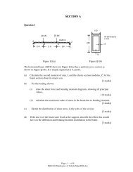
Fig 1. 4/5 ‘N’ rotors scaled <strong>for</strong> the family <strong>of</strong> screw air compressors
This pr<strong>of</strong>ile/configuration combination has the advantage <strong>of</strong> high displacement with a short<br />
sealing line together with a small blow-hole area, when optimised <strong>for</strong> medium pressure air<br />
compression. A low torque to the gate rotor and involute rotor contact resulted in low rotor<br />
surface stress, while ‘negative’ torque on the gate rotor causes contact along the straight<br />
flanks, which minimises the interlobe leakage path.<br />
A s<strong>of</strong>tware package <strong>for</strong> design <strong>of</strong> screw compressors developed by the authors, described in<br />
Hanjalic and Stosic, 1997 [8], was used to determine the optimum rotor size and speed and<br />
the compressor volume ratio. <strong>The</strong> output from this, which included almost every aspect <strong>of</strong><br />
geometric and thermodynamic modelling and capacity was transmitted directly into a CAD<br />
drawing system. <strong>The</strong> entire flow range required was thereby covered by only 5 rotor sizes, all<br />
<strong>of</strong> the same L/D ratio <strong>of</strong> 1.55, thus unifying the rotor pr<strong>of</strong>iles and compressor shapes and<br />
<strong>for</strong>ms <strong>for</strong> the whole family. <strong>The</strong> main rotor diameters thus selected were 73, 102, 159, 225<br />
and 284 mm diameter and these are shown in Fig. 1 together with a photograph <strong>of</strong> one <strong>of</strong><br />
them.<br />
As can be seen in Fig 1, ‘N’ rotors have very strong gate pr<strong>of</strong>ile lobes. This allows higher<br />
cutting <strong>for</strong>ces to be applied during their manufacturing by the milling manufacturing<br />
procedure. <strong>The</strong> milling tool to produce them was also designed at City University.<br />
<strong>The</strong> main per<strong>for</strong>mance parameters calculated by the simulation program, are presented in<br />
logarithmic coordinates in Fig. 2.<br />
Fig 2 Predicted Per<strong>for</strong>mance <strong>of</strong> the Elgi family <strong>of</strong> oil-flooded air compressors
3 MECHANICAL DESIGN OF THE COMPRESSOR FAMILY<br />
On completion <strong>of</strong> the rotor pr<strong>of</strong>ile generation and thermodynamic per<strong>for</strong>mance estimation by the<br />
design s<strong>of</strong>tware, the component sizes and shapes, as well as the resulting <strong>for</strong>ce loads thus<br />
estimated, were transferred to a CAD system by means <strong>of</strong> a full internal interface. In addition,<br />
modern design concepts, such as late closing <strong>of</strong> the suction port and early exposure <strong>of</strong> the<br />
discharge port were included, together with improved bearing and seal specification, to<br />
maximise the compressor endurance and reliability, as presented by Stosic et al, 1997 [9].<br />
Fig. 3 <strong>The</strong> smallest compressor <strong>of</strong> the family, 4/5-73 mm
<strong>The</strong> key factor <strong>for</strong> all screw compressor applications is the rotor design. Although advanced<br />
rotor pr<strong>of</strong>iles are a necessary condition <strong>for</strong> a screw compressor to be efficient, all other<br />
components must be designed to enhance rotor superiority if their full advantage is to be<br />
achieved. Thus rotor to housing clearances, especially at the high pressure end must be properly<br />
selected. This in turn requires either expensive bearings with smaller clearances or cheaper<br />
bearings with their clearances reduced to an acceptable value by preloading. <strong>The</strong> latter practice<br />
was chosen as the most convenient and economic solution.<br />
A screw compressor, especially <strong>of</strong> the oil flooded type, which operates with high pressure<br />
differences, is heavily loaded by axial and radial <strong>for</strong>ces which are transferred to the housing by<br />
the bearings. Rolling element bearings are normally chosen <strong>for</strong> small and medium screw<br />
compressors and these must be carefully selected to obtain a satisfactory design. Usually two<br />
bearings are employed on the discharge end <strong>of</strong> the rotor shafts in order to absorb the radial and<br />
axial loads separately. Also the distance between the rotor centre lines is in part determined by<br />
the bearing size and internal clearance. An assembly drawing <strong>of</strong> the compressor is shown in Fig<br />
3 in which the bearing arrangement can be seen.<br />
<strong>The</strong> same oil is used <strong>for</strong> rotor flooding and <strong>for</strong> bearing lubrication but the supply to and<br />
evacuation from the bearings is separate to minimise the bearing friction losses. Oil is injected<br />
into the compressor chamber at the place where thermodynamic calculations show the air and oil<br />
inlet temperature to coincide. <strong>The</strong> position is defined on the rotor helicoid with the injection hole<br />
located so that the oil enters tangentially in line with the gate rotor tip in order to recover as much<br />
as possible <strong>of</strong> the oil kinetic energy.<br />
Special care was given to minimise the flow losses in the suction and discharge ports. <strong>The</strong><br />
suction port is positioned in the housing to let the air enter with the fewest possible bends and the<br />
air approach velocity is kept low by making the flow area as large as possible. <strong>The</strong> photograph in<br />
Fig 3 demonstrates this feature. <strong>The</strong> discharge port size was first determined by estimating the<br />
built-in-volume ratio required <strong>for</strong> optimum thermodynamic per<strong>for</strong>mance. It was then increased<br />
in order to reduce the exit air velocity and hence obtain the minimum combination <strong>of</strong> internal<br />
and discharge flow losses.<br />
<strong>The</strong> cast iron casing, which was carefully dimensioned to minimize its weight, contained a<br />
rein<strong>for</strong>cing bar visible in Fig. 3 across the suction port to improve its rigidity at higher pressures.<br />
After casting it was hydraulically tested at a pressure <strong>of</strong> 22.5 bar.<br />
<strong>The</strong> mechanical design <strong>of</strong> the compressor family was per<strong>for</strong>med interactively and involved close<br />
liaison between the authors at the Centre and Elgi engineers. <strong>The</strong> first two compressors were<br />
designed fully by the Centre, while the third and fourth compressors were designed by the<br />
manufacturer’s designer under direct supervision <strong>of</strong> the Centre. Finally, the fifth compressor was<br />
designed by the manufacturer’s engineers. All other activities, including tool and rotor<br />
manufacture and compressor production and assembly were per<strong>for</strong>med at the manufacturer’s<br />
premises in India.
4 TESTING OF THE COMPRESSOR PROTOTYPES<br />
Two test rigs were used <strong>for</strong> simultaneous testing <strong>of</strong> the compressor prototypes, one at City<br />
University and another at Elgi. Both test rigs meet all Pneurop/Cagi requirements <strong>for</strong> screw<br />
compressor acceptance tests. <strong>The</strong> compressors were tested according to ISO 1706 and their<br />
delivery flow was measured following BS 5600. High accuracy test equipment was used <strong>for</strong> the<br />
measurement <strong>of</strong> all relevant parameters.<br />
Fig. 4 Compressor test layout and the computer screen<br />
Fig. 5 Comparison <strong>of</strong> the estimated and measured flow in function <strong>of</strong> compressor power,<br />
Compressor 4/5-73
Fig. 6 Comparison <strong>of</strong> the estimated and measured flow in function <strong>of</strong> compressor power,<br />
Compressor 4/5-102<br />
Fig. 5 Comparison <strong>of</strong> the estimated and measured flow in function <strong>of</strong> compressor power,<br />
Compressor 4/5-159
<strong>The</strong> measurements were taken by transducers and both recorded and processed in a<br />
computerized data logger <strong>for</strong> real time presentation. A screen record <strong>of</strong> the compressor<br />
measurement is given in Fig. 4. A Diesel engine prime mover <strong>of</strong> 100 kW maximum output,<br />
which may operate at variable speed, was used as a prime mover. This enabled the testing <strong>of</strong> oilflooded<br />
screw compressors with discharge rates <strong>of</strong> up to 16 m 3 /min.<br />
At the time <strong>of</strong> writing <strong>of</strong> this paper, three compressor sizes had been produced and tested.<br />
Measured values were used to calculate compressor flow, power and specific power and the oil<br />
injection rate was estimated by means <strong>of</strong> a heat balance. Both the predicted and measured test<br />
results <strong>of</strong> three compressor sizes, namely the 4/5-73 mm, 4/5-102 and 4/5-159 mm units are<br />
presented in Figs 5, 6 and 7 in the <strong>for</strong>m <strong>of</strong> compressor flow as a function <strong>of</strong> input power. As may<br />
be observed, the correlation between the estimated and measured values is good and it may be<br />
concluded from the plot <strong>of</strong> specific power, given in Fig 2 that the compressor efficiency is higher<br />
than in majority <strong>of</strong> commercially available compressors.<br />
<strong>The</strong> experimentally derived compressor per<strong>for</strong>mance data has been compared with results taken<br />
from brochures issued by all well known manufactures <strong>of</strong> equivalent machines. It should be<br />
noted that there are wide variations between machines and it is normal practice to base such<br />
publications on the best results. Despite this, no published results could be found with better<br />
per<strong>for</strong>mance than that recorded in this paper.<br />
5 CONCLUSION<br />
<strong>The</strong> execution <strong>of</strong> the development <strong>of</strong> the compressor family described in this paper has been<br />
used as an opportunity to publicise the advantages <strong>of</strong> advanced simulation models and<br />
modern rotor pr<strong>of</strong>iling techniques to determine the optimum rotor pr<strong>of</strong>ile, size and speed, the<br />
volume ratio and the shape and position <strong>of</strong> the suction and discharge and oil port. <strong>The</strong>se have<br />
been made easy to incorporate into the design by the ability to transfer the output data thus<br />
derived directly in a CAD system. However, it should be noted that, apart from the<br />
improvements made due to the superior rotor pr<strong>of</strong>ile and computer optimisation, attention was<br />
paid to every detail <strong>of</strong> the designs such as the ports, the oil injection system and the bearings<br />
in order to derive the full benefit possible from this approach. <strong>The</strong> high efficiencies obtained<br />
on test, as well as the reduced size and weight <strong>of</strong> these machines, compared to the models which<br />
they have been designed to replace, all confirm the validity <strong>of</strong> this approach.<br />
REFERENCES<br />
1 Sakun I.A, 1960: Vintovie kompresorii, (screw <strong>Compressors</strong>) Mashinostroenie Leningrad<br />
2 Amosov P.E, Bobrikov, N.I, Schwartz A.I, Vernii A.L, 1977: Vintovie kompresornie mashinii - Spravochnik,<br />
(Handbook <strong>of</strong> <strong>Screw</strong> Comp ressor Machines) Mashinstroienie, Leningrad<br />
3 Rinder L, 1979: Schraubenverdichter (<strong>Screw</strong> <strong>Compressors</strong>), Springer Verlag, New York<br />
4 O'Neill P.A, 1993: Industrial <strong>Compressors</strong>, <strong>The</strong>ory and Equipment, Butterworth-Heinemann, Ox<strong>for</strong>d<br />
5 Arbon A, 1994: Twin Shaft <strong>Compressors</strong> in Gas Process Industry, IMechE Publications London<br />
6 Xing Z. W, 2000: <strong>Screw</strong> <strong>Compressors</strong>, Machine Press, Beijing<br />
7 Stosic N, Hanjalic K, 1997: Development and Optimization <strong>of</strong> <strong>Screw</strong> Machines with a Simulation Model, Part<br />
I: Pr<strong>of</strong>ile Generation, ASME Transactions, Journal <strong>of</strong> Fluids Engineering, Vol 119, p 654<br />
8 Hanjalic K, Stosic N, 1997: Development and Optimization <strong>of</strong> <strong>Screw</strong> Machines with a Simulation Model, Part<br />
II: <strong>The</strong>rmodynamic Per<strong>for</strong>mance Simulation and <strong>Design</strong> Optimization, ASME Transactions, Journal <strong>of</strong> Fluids<br />
Engineering, Vol 119, p 659<br />
9 Stosic N, Smith I. K, Kovacevic A, Aldis C. A, 1997: <strong>The</strong> <strong>Design</strong> <strong>of</strong> a Twin-screw Compressor Based on a New<br />
Pr<strong>of</strong>ile, Journal <strong>of</strong> Engineering <strong>Design</strong>, Vol 8, 389