Improving screw compressor performance - Staff.city.ac.uk - City ...
Improving screw compressor performance - Staff.city.ac.uk - City ...
Improving screw compressor performance - Staff.city.ac.uk - City ...

You also want an ePaper? Increase the reach of your titles
YUMPU automatically turns print PDFs into web optimized ePapers that Google loves.
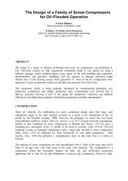
<strong>Improving</strong> <strong>screw</strong> <strong>compressor</strong> <strong>performance</strong><br />
Nikola StoÄi , Ian K. Smith, Ahmed Kova evi<br />
Centre for Positive Displ<strong>ac</strong>ement Compressor Technology, <strong>City</strong> University, London, U.K.<br />
Jung-<strong>uk</strong> Kim, Jinwoo Park<br />
Airplus Co Ltd, Korea<br />
ABSTRACT<br />
Screw <strong>compressor</strong> efficiency is improved by reducing internal leakage and this can be effected<br />
by minimising the clearance between the rotors and the casing. The effect on <strong>performance</strong> of<br />
three f<strong>ac</strong>tors which influence the working clearance was analysed. These are: the interlobe<br />
clearance, adjusted to the rotor temperature change, rotor cont<strong>ac</strong>t on the lobe flat side and<br />
displ<strong>ac</strong>ement of the discharge bearing centres. Due <strong>ac</strong>count of the results of this study was<br />
taken in the design of a large <strong>screw</strong> <strong>compressor</strong>, which was then built and tested. The<br />
efficiencies obtained were the highest ever reported for <strong>screw</strong> <strong>compressor</strong>s in the open<br />
literature. This confirmed the validity of this appro<strong>ac</strong>h.<br />
1 INTRODUCTION<br />
Since the <strong>performance</strong> of <strong>screw</strong> <strong>compressor</strong>s is highly affected by leakage, any reduction of the<br />
clearances within them must improve their efficiency.<br />
Modern rotor manuf<strong>ac</strong>turing methods, such as grinding with simultaneous measurement,<br />
control and correction of the profile, enable the profile tolerance to be maintained within Ä5<br />
m. This enables the clearances between the rotors to be kept below 15 m. With such small<br />
clearances, rotor cont<strong>ac</strong>t is very likely and hence the profile and its clearance distribution must<br />
be generated in such a manner that damage or seizure will be avoided should this occur.<br />
Current pr<strong>ac</strong>tice to avoid rotor cont<strong>ac</strong>t and seizure is to make clearances larger than required by<br />
manuf<strong>ac</strong>turing limitations. However, the clearances can be reduced by making their<br />
distribution non-uniform around the profile so that should hard rotor cont<strong>ac</strong>t occur, it will not<br />
be in rotor areas where sliding motion between the rotors is dominant.<br />
The design of <strong>screw</strong> <strong>compressor</strong>s is an inter<strong>ac</strong>tive process in which the <strong>performance</strong> estimated<br />
in the design process is compared with that obtained from prototype testing. The prototype is<br />
then repeatedly modified until the desired values are obtained. However, as more <strong>ac</strong>curate<br />
methods of simulating the <strong>performance</strong> become available, the need for modifying the prototype<br />
can be minimised. To this end, the authors have developed a suite of subroutines for the<br />
estimation of <strong>screw</strong> <strong>compressor</strong> <strong>performance</strong>. These include f<strong>ac</strong>ilities for the generation of new
otor profiles, the estimation of the thermodynamic processes within the <strong>compressor</strong> and hence,<br />
the <strong>performance</strong> changes that are likely to result from modifying the profiles. The <strong>ac</strong>cur<strong>ac</strong>y of<br />
these estimates has been enhanced by extensive comparison with test results on many<br />
m<strong>ac</strong>hines, followed by modification of the model to obtain better agreement not only with the<br />
bulk parameters, such as flow delivery and power consumption, but also with the cyclic<br />
variation of important instantaneous values, such as the pressure distribution within the<br />
<strong>compressor</strong> working chamber. More details of this are given by Hanjalic and Stosic 1997.<br />
Essentially, the computational procedure is as follows:<br />
(i)<br />
(ii)<br />
(iii)<br />
A pre-processor generates the lobe profiles from which the complete <strong>screw</strong> rotor<br />
pair is formed and the working chamber volume function is generated.<br />
The <strong>performance</strong> is estimated by the numerical solution of a set of differential<br />
equations, which <strong>ac</strong>count for the conservation of mass, momentum and energy and<br />
which include estimates of the thermodynamic properties of the working fluid and<br />
associated flow processes. The results include not only estimates of bulk<br />
parameters, such as the delivery flow rate and power input, but also instantaneous<br />
values of how the working fluid pressure and temperature vary within the<br />
<strong>compressor</strong> cycle.<br />
A post-processing program is then used to present the results in graphical and<br />
tabular form.<br />
This procedure was used to estimate what effect the three main f<strong>ac</strong>tors that govern the<br />
<strong>compressor</strong> working clearance have on its <strong>performance</strong>. The results thus obtained were then<br />
applied to the design of a 4/5-220 mm rotor diameter oil injected air <strong>compressor</strong>.<br />
2 ROTOR MODIFICATION AND ITS EFFECT ON PERFORMANCE<br />
In order to maximise <strong>screw</strong> <strong>compressor</strong> delivery rates and efficiencies, interlobe clearances<br />
must be made as small as possible without the likelihood of hard rotor cont<strong>ac</strong>t between the<br />
rotors, in regions where the sliding velo<strong>city</strong> is high. Three main effects must be allowed for in<br />
the design in order to ensure this.<br />
2.1 Thermal Expansion of the Rotors and Housing<br />
Although the temperature range over which <strong>screw</strong> <strong>compressor</strong>s operate is not large, the effects<br />
of thermal expansion are highly significant if the small clearances required between the rotors<br />
and between the rotors and the housing are to be maintained under working conditions. Thus,<br />
the rotor clearances obtained under manuf<strong>ac</strong>turing conditions must be estimated while taking<br />
<strong>ac</strong>count of thermal distortion that will occur when the <strong>compressor</strong> re<strong>ac</strong>hes its operating<br />
temperature and pressure and the calculation must allow for the unequal expansion of the rotors<br />
in different coordinate directions. An example of this is given in Fig. 1, where the left diagram<br />
shows the estimated clearance distribution when the rotors are cold, while, the centre and right<br />
diagrams show the clearances after the rotors re<strong>ac</strong>h their working temperatures. Additional<br />
information about the <strong>screw</strong> <strong>compressor</strong> clearance management and other means of improving<br />
efficiency may be found in Stosic, 2004.<br />
Despite the cold clearances being adequate, under operating conditions, rotor cont<strong>ac</strong>t may<br />
occur on the round flank, as shown in Fig 1b, or on the flat flank, as shown in Fig 1c.<br />
14
a) Cold rotors, b) Rotor cont<strong>ac</strong>t on the round f<strong>ac</strong>e, c) Cont<strong>ac</strong>t on the flat f<strong>ac</strong>e<br />
Fig. 1 Rotor interlobe clearance distribution<br />
1-main, 2-gate, 3-rotor external and 4-pitch circles, 5-sealing line,<br />
6-clearance distribution, 7-area between the rotors and housing<br />
Fig 2 Screw rotor profile<br />
2.2 Rotor cont<strong>ac</strong>t on the lobe flat side<br />
Oil flooded <strong>compressor</strong>s have direct cont<strong>ac</strong>t between their rotors. In well designed rotors, the<br />
clearance distribution will be set so that this is first made along their, so called, cont<strong>ac</strong>t bands,<br />
which are positioned close to the rotor pitch circles. Since the relative motion between the<br />
cont<strong>ac</strong>ting lobes in this region is almost pure rolling, the danger of their seizing, as a result of<br />
sliding cont<strong>ac</strong>t, is thereby minimised. As already shown in Fig 1, the cont<strong>ac</strong>t band may be either<br />
on the rotor round flank b), or on the rotor flat flank c).<br />
15
The traditional appro<strong>ac</strong>h is to maintain a high, so called, positive gate rotor torque, which<br />
ensures round flank cont<strong>ac</strong>t. What is not widely appreciated is that there are significant<br />
advantages to be gained by maintaining a negative gate rotor torque to ensure that cont<strong>ac</strong>t,<br />
when it occurs, will be on the flat f<strong>ac</strong>e. The reason for this can be understood by examination<br />
of the sealing line lengths, shown as item 5 in Fig 2. Here it can be seen clearly that the flat<br />
flank sealing line is much longer than that of the round flank. Thus, minimising the clearance<br />
on the flat flank will reduce the interlobe leakage more than minimising the round flank<br />
clearance. Also, negative gate torque is <strong>ac</strong>hieved by making the gate rotor lobes thicker and<br />
the main rotor lobes correspondingly thinner. The displ<strong>ac</strong>ement is thereby increased. Thus both<br />
these effects lead to higher <strong>compressor</strong> flows and efficiencies.<br />
2.3 Displ<strong>ac</strong>ement of the bearing centres<br />
Since there must be some clearance in the bearings, the pressure loads will tend to push the<br />
rotors apart and displ<strong>ac</strong>e their centres from their design position with respect to the <strong>compressor</strong><br />
housing. Thus, if the bearing centres are set to be the same as those of the rotors, the rotors will<br />
be eccentric and as a result the clearance between the rotors and housing will be smaller at the<br />
low pressure side of the rotors and larger at the high pressure side. Since leakage is caused by<br />
the pressure difference, this displ<strong>ac</strong>ement creates the least favourable rotor position for<br />
efficient <strong>compressor</strong> operation.<br />
Also the resulting rotor displ<strong>ac</strong>ements from their design positions may result in cont<strong>ac</strong>t<br />
between the rotor tips and the housing unless allowance is made for them during the design.<br />
The situation can be remedied by making the bearing centre distance smaller than that of the<br />
rotor housing and aligned to maintain a uniform clearance between the rotors and housing. To<br />
minimise the rotor interlobe clearance, the bearing centre distance must be even further<br />
reduced.<br />
2.4 Optimising the rotor profile<br />
Although rotor profiles are designed to minimise the blow-hole area, this is frequently<br />
associated with increase in the sealing line length. The optimum profile shape is therefore that<br />
which minimises the sum of both the blow-hole and sealing line leakage areas.<br />
2.5 Performance simulations of optimised rotors<br />
The three possible improvements described in Sections 2.1-2.3 were applied systematically to<br />
<strong>performance</strong> simulations of an oil flooded air <strong>compressor</strong> of 223mm male rotor diameter when<br />
running at a shaft speed of 2100rpm with a suction pressure of 1 bar and a discharge pressure of 9<br />
bar. The results of these are presented in Table 1.<br />
Table 1 Compressor Performance at 1500 rpm and 9 bars<br />
Q[m 3 /min] v P[kW] Psp[kW/m3/min] t out [ o C]<br />
15.9 0.901 103.7 6.506 0.835 86<br />
16.1 0.911 102.9 6.383 0.850 85<br />
16.2 0.916 102.6 6.327 0.858 84<br />
16.0 0.906 103.7 6.444 0.843 85<br />
16
The first row gives the results without any modification. The second row shows the <strong>performance</strong><br />
obtained by introducing Åhot clearancesÇ. The third row shows the effect of displ<strong>ac</strong>ing the<br />
discharge bearings 50 m in the direction opposite to that of the line of <strong>ac</strong>tion of the pressure<br />
radial forces and the fourth row represent the effects of inducing rotor cont<strong>ac</strong>t on the flat flank<br />
side.<br />
3 MODIFICATIONS IN SCREW COMPRESSOR DESIGN<br />
Following the above analysis, a 220 mm diameter rotor oil flooded 4/5 air <strong>compressor</strong> was<br />
designed with a L/D ratio of 1.55, including all the proposed improvements described in Section<br />
2. The rotors are shown in Fig 3 and its estimated <strong>performance</strong> in Figs 4 and 5.<br />
Fig. 3 4/5 220 mm rotors<br />
The rotors were made of steel and were manuf<strong>ac</strong>tured by grinding, thus ensuring excellent<br />
precision and cont<strong>ac</strong>t. The rotor L/D ratio was kept optimally low to minimise deflection,<br />
maintain favourable dynamic char<strong>ac</strong>teristics and <strong>ac</strong>hieve the required <strong>compressor</strong> comp<strong>ac</strong>tness.<br />
The housing was designed for manuf<strong>ac</strong>ture from normalized nodular iron for easy and precise<br />
m<strong>ac</strong>hining, while ensuring both tightness and structural integrity.<br />
Cylindrical roller bearings and two-point cont<strong>ac</strong>t ball bearings for the axial loads were employed<br />
to ensure long operating life. A high quality mechanical shaft seal was provided for safe and<br />
reliable operation.<br />
After manuf<strong>ac</strong>ture of all the components, the <strong>compressor</strong> was assembled and tested.<br />
17
Fig. 4 Estimated flow as function of <strong>compressor</strong> power<br />
Fig. 5 Estimated specific power as function of shaft speed<br />
18
4 TESTING OF THE PROTOTYPE COMPRESSOR<br />
A photograph of the test rig with the <strong>compressor</strong> installed in it is presented in Fig 6 and a basic<br />
piping and instrumentation diagram of it is shown in Fig 7. The <strong>compressor</strong> was driven by a<br />
100 kW electrical motor, with its speed controlled by a frequency converter. A six band belt<br />
drive with a speed reduction ratio of 1:2.52 was used to transmit the power from the motor to<br />
the <strong>compressor</strong> drive shaft, which was mounted on two pedestal bearings to resist the side load<br />
imposed on it. After discharge from the <strong>compressor</strong>, oil was removed from the compressed air<br />
in a separator. The separated oil was then recirculated into the <strong>compressor</strong>, via a water cooled<br />
heat exchanger, and reinjected through a nozle, as a result of the pressure difference between<br />
the discharge pressure and the pressure in the <strong>compressor</strong> working chamber at the oil<br />
admission point. The separated discharge air was then passed through an orifice plate, in order<br />
to determine its flow rate and then vented to a flue below the test cell.<br />
Fig. 6 Layout of the test rig<br />
Instrumentation scheme of the test rig is shown in Fig 7. The measurements from which<br />
<strong>performance</strong> estimates of the <strong>compressor</strong> were derived are <strong>compressor</strong> speed and torque,<br />
<strong>compressor</strong> inlet pressure and temperature p 1 and t 1 , <strong>compressor</strong> discharge pressure and<br />
temperature p 2 and t 2 , the orifice plate inlet pressure and temperature p 3 and t 3 and the pressure<br />
drop <strong>ac</strong>ross the orifice plate p. The orifice plate section of the discharge pipe was 100 mm<br />
diameter and the orifice platewas designed <strong>ac</strong>cording to BS 1042. Additionally, the<br />
atmospheric pressure p 0 and temperature t 0 were measured.<br />
19
Fig. 7 Instrumentation of the test rig<br />
Apart from the laboratory atmospheric pressure, which was input manually, all measurements<br />
were obtained from electrically generated signals derived directly from the speed, torque,<br />
pressure and temperature measurements. These were logged in an Instrunet data logger,<br />
programmed to display average values at 5 second intervals. In addition, instantaneous values<br />
were displayed visually by a variety of digital electronic meters and centrally at the computer<br />
screen. The latter, were very helpful in setting up the required test conditions. The recorded<br />
data was then input to a computer as an unformatted data file for further processing. The test<br />
schedule employed followed the guidelines laid down by PNEUROP and CAGI in document<br />
PN2CPTC1.<br />
The test data were obtained at discharge pressures of 7, 9 and 11 bars. The estimated delivery,<br />
power and specific power are compared with the experimentally derived values, as shown in<br />
Figs 8 and 9. The results show good agreement between the predicted and test values.<br />
The specific power obtained, as a result of the optimisation procedure described, is 5-8 %<br />
lower than that of any other m<strong>ac</strong>hine of this type, as reported to date in published literature.<br />
20
Fig. 8 Comparison of the estimated and measured flow and power<br />
Fig. 9 Comparison of the estimated and measured specific power<br />
21