Owner's Manual - Fostex
Owner's Manual - Fostex Owner's Manual - Fostex
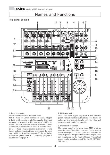
Top panel section Model VM88 Owner’s Manual Names and Functions 1. Input connector External sound sources are input here. MIC 1 - 4 are for Canon connectors (XLR-3-31; pin 2=hot), which comply to mic/line signals. The input gain can be trimmed within a range of -50dBu ~ - 10dBu. Because phantom power is available at these connectors, condenser mics can also be connected. LINE 1 ~ 4 are TRS phone jacks exclusively for line inputs and each input gain can be trimmed the same as with MIC 1 ~ 4, within a range of -30dBu ~ +10dBu. For details, please refer to “Connecting peripheral equipment” on page 9. 2. AUX send jack AUX SEND level signal adjusted in the channel parameter edit mode is output here. For details on adjusting the output signals, refer to “Channel parameter edit mode” on page 20. 3. Stereo out connector The mixed signal to be input to an MTR or other mixer is output from this connector. Connectors for balanced output (XLR-3-32 type) and unbalanced output (phone) are provided and the output level can be adjusted by the MASTER fader. The output signal can be switched on/off by the ST OUT ON/ OFF switch. 4
Model VM88 Owner’s Manual 4. Stereo out ON/OFF switch Stereo out signal ON/OFF is controlled by this switch. For details, please refer to “Normal mix mode” on page 15. 5. Monitor in jack External signals are input here. The input signal is adjusted via the MON IN GAIN knob and directly mixed into the monitor circuit, so that it can be monitored at the PHONES and MON OUT L, R jacks together with a monitor signal selected by the MON SEL switch. 6. Monitor out jack Powered monitoring speakers or an amplifier + speaker combination are plugged in here. The signal to be monitored is selected by the MON SEL switch and the output is adjusted with the MON OUT GAIN knob. For details, please refer to “Connecting peripheral equipment” on page 9. 7. Foot switch connecting jack A foot switch (Fostex Model 8051) is plugged in here. The foot switch function can be changed by the [SETUP mode] explained later. The initial setting recalls the scene memory. Refer to page 33 for details. 8. Headphone jack The monitoring headphone is connected here. Use the PHONES GAIN control to adjust the sound level. 9. Monitor output adjusting knob This controls the sound volume at the MON OUT L, R jacks. 10. Headphone volume This adjusts the monitor headphone sound volume. 11. Monitor input adjusting knob Use this to adjust the input signal level from the MON IN jack. 12. Monitor select switch This is for selecting the monitor signal to be output at the MON OUT L, R and PHONES jacks. Either one signal in the stereo buss, AUX 1 buss or AUX 2 buss can be selected. 13. Scene Recall key This is pressed to recall the scene memory explained later. Refer to [Recall of the scene memory] on page 30 for details. 14. Scene Store key This is pressed to store a scene memory. Refer to [Storing the scene memory] on page 30 for details. 15. Effect 2 key This is pressed to select the EFF 2 effects type or the parameter to be edited. Also, if this key is pressed while pressing the EXIT key, muting of EFF 2 can be switched ON/OFF. Refer to [Effect edit mode] on page 24 for details. 16. Effect 1 key This is pressed to select the EFF 1 effects type or the parameter to be edited. Also, if this key is pressed while pressing the EXIT key, muting of EFF 1 can be switched ON/OFF. Refer to [Effect edit mode] on page 24 for details. 17. Enter key This is used to accept the current mode setting. This key will setup scene memory mode (page 30), the setup mode (page 33) and also the setup of effects type (page 26). Please refer to their respective explanation for details. 18. Exit key This is used to exit from all modes but the normal mix mode. This key works for the channel parameter edit mode (page 20), the effects edit mode (page 24), the scene memory mode (page 30) and the setup mode (page 33). Refer to their respective explanations for details. 19. Data encoder This dial is rotated to make settings such as setup of PAN and EQ. This dial works in the channel parameter edit mode (page 20), the scene memory mode (page 30) and the effects edit mode (page 24). Refer to their respective explanations for details. 20. Phantom LED When the phantom power supply ON/OFF setting in the setup mode is set to ON, the LED will light but and extinguish when set to OFF. The phantom power supply is OFF from the factory. For details on ON/ OFF of phantom power supply, refer to “Setup mode” on page 33. 21. Master fader This adjusts the master level of signal output from the STEREO OUT L, R jacks and DIGITAL OUTPUT connector. 22. Input fader Signal levels of sound sources connected to each IN- PUT jack can be adjusted with these fader. Input faders 5/6 and 7/8 controls both channels at the same time. 23. PAN/EQ select key The channel parameter edit mode is entered when this key is pressed to setup of PAN and EQ. Refer to [Channel parameter edit mode] on page 20 for details. 24. EFF/AUX select key The channel parameter edit mode is entered by pressing so the EFFECT send output and AUX send output can be adjusted. If this key is pressed while pressing the EXIT key, PRE/POST of EFFECT send/AUX send 5
- Page 1 and 2: Owner’s Manual Model Eight Channe
- Page 3: Model VM88 Owner’s Manual Table o
- Page 7 and 8: Model VM88 Owner’s Manual Rear pa
- Page 9 and 10: OUT DIGITAL OPTICAL IN RESET AC IN
- Page 11 and 12: Model VM88 Owner’s Manual (3) INS
- Page 13 and 14: Model VM88 Owner’s Manual < Examp
- Page 15 and 16: Normal Mix Mode Model VM88 Owner’
- Page 17 and 18: CH ON/CH SEL -40 Model VM88 Owner
- Page 19 and 20: Model VM88 Owner’s Manual < Pleas
- Page 21 and 22: Setup method for EQ setting Model V
- Page 23 and 24: Model VM88 Owner’s Manual PRE/POS
- Page 25 and 26: About the effect types 25 Model VM8
- Page 27 and 28: Model VM88 Owner’s Manual 3. Pres
- Page 29 and 30: Model VM88 Owner’s Manual Doublin
- Page 31 and 32: Model VM88 Owner’s Manual Level a
- Page 33 and 34: Setup Mode Model VM88 Owner’s Man
- Page 35 and 36: Model VM88 Owner’s Manual * Setup
- Page 37 and 38: Model VM88 Owner’s Manual * Setup
- Page 39 and 40: Specifications Model VM88 Owner’s
Top panel section<br />
Model VM88 Owner’s <strong>Manual</strong><br />
Names and Functions<br />
1. Input connector<br />
External sound sources are input here.<br />
MIC 1 - 4 are for Canon connectors (XLR-3-31; pin<br />
2=hot), which comply to mic/line signals. The input<br />
gain can be trimmed within a range of -50dBu ~ -<br />
10dBu. Because phantom power is available at these<br />
connectors, condenser mics can also be connected.<br />
LINE 1 ~ 4 are TRS phone jacks exclusively for line<br />
inputs and each input gain can be trimmed the same<br />
as with MIC 1 ~ 4, within a range of -30dBu ~ +10dBu.<br />
For details, please refer to “Connecting peripheral<br />
equipment” on page 9.<br />
2. AUX send jack<br />
AUX SEND level signal adjusted in the channel<br />
parameter edit mode is output here. For details on<br />
adjusting the output signals, refer to “Channel<br />
parameter edit mode” on page 20.<br />
3. Stereo out connector<br />
The mixed signal to be input to an MTR or other<br />
mixer is output from this connector. Connectors for<br />
balanced output (XLR-3-32 type) and unbalanced<br />
output (phone) are provided and the output level<br />
can be adjusted by the MASTER fader. The output<br />
signal can be switched on/off by the ST OUT ON/<br />
OFF switch.<br />
4


