
You also want an ePaper? Increase the reach of your titles
YUMPU automatically turns print PDFs into web optimized ePapers that Google loves.
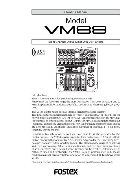
Owner’s <strong>Manual</strong><br />
Model<br />
Eight Channel Digital Mixer with DSP Effects<br />
Introduction<br />
Thank you very much for purchasing the <strong>Fostex</strong> VM88.<br />
Please read the following to get the most satisfaction from your purchase, and to<br />
learn important information about safety precautions when using <strong>Fostex</strong> products.<br />
The VM88 digital mixer does all internal signal processing digitally.<br />
The input features 8 analog channels, of which 4 channels (XLR or PHONE) are for<br />
microphones; digital inputs (S/P DIF or ADAT) via optical connection are provided.<br />
For outputs, an optical digital output (S/P DIF or ADAT) in addition to stereo out<br />
(balanced/unbalanced), headphone out, AUX send/out and monitor outs in analog<br />
are also provided. An insert function is featured in channels 1 - 4 for more<br />
flexibility during mixing.<br />
In addition to each input channel, an three band EQ is also provided for the<br />
master output. The VM88 also incorporates high performance DSP multi-effects<br />
on two channels that operate by A.S.P. (<strong>Fostex</strong> Advanced Signal Processing Technology*)<br />
exclusively developed by <strong>Fostex</strong>. This allows a wide range of equalizing<br />
and effects processing. All settings, including mix and effects settings, are stored<br />
in scene memory, and a desired scene memory can be recalled instantaneously.<br />
Although small and lightweight, the VM88 is a high performance unit. Please<br />
read this manual carefully before operation to understand all functions of the<br />
VM88.<br />
* See page 24 for more details on the A.S.P. (<strong>Fostex</strong> Advanced Signal Processing Technology).
Model VM88 Owner’s <strong>Manual</strong><br />
CAUTION<br />
CAUTION: TO REDUCE THE RISK OF ELECTRIC SHOCK,<br />
DO NOT REMOVE COVER (OR BACK).<br />
NO USER - SERVICEABLE PARTS INSIDE.<br />
REFER SERVICING TO QUALIFIED SERVICE PERSONNEL.<br />
"WARNING"<br />
RISK OF ELECTRIC SHOCK<br />
DO NOT OPEN<br />
"TO REDUCE THE RISK OF FIRE OR ELECTRIC<br />
SHOCK, DO NOT EXPOSE THIS APPLIANCE TO RAIN<br />
OR MOISTURE."<br />
SAFETY INSTRUCTIONS<br />
1. Read Instructions - All the safety and operating instructions<br />
should be read before the appliance is operated.<br />
2. Retain Instructions - The safety and operating instructions<br />
should be retained for future reference.<br />
3. Heed Warnings - All warnings on the appliance and in the<br />
operating instructions should be adhered to.<br />
4. Follow Instructions - All operating and use instructions should<br />
be followed.<br />
5. Water and Moisture - The appliance should not be used near<br />
water - for example, near a bathtub, washbowl, kitchen sink,<br />
laundry tub, in a wet basement, or near a swimming pool, and<br />
the like.<br />
6. Carts and Stands - The appliance should be used only with a<br />
cart or stand that is recommended by the manufacturer.<br />
An appliance and cart combination should be moved with care.<br />
Quick stops, excessive force, and uneven surfaces may cause<br />
the appliance and cart combination to overturn.<br />
7. Wall or Ceiling Mounting - The appliance should be mounted<br />
to a wall or ceiling only as recommended by the manufacturer.<br />
8. Ventilation - The appliance should be situated so that its location<br />
or position dose not interfere with its proper ventilation. For<br />
example, the appliance should not be situated on a bed, sofa,<br />
rug, or similar surface that may block the ventilation openings;<br />
or, placed in a built-in installation, such as a bookcase or cabinet<br />
that may impede the flow of air through the ventilation openings.<br />
9. Heat - The appliance should be situated away from heat sources<br />
such as radiators, heat registers, stoves, or other appliances<br />
(including amplifiers) that produce heat.<br />
10. Power Sources - The appliance should be connected to a power<br />
supply only of the type described in the operating instructions or as<br />
marked on the appliance.<br />
11. Grounding or Polarization - The precautions that should be taken<br />
so that the grounding or polarization means of an appliance is not<br />
defeated.<br />
CAUTION:<br />
TO PREVENT ELECTRIC SHOCK, MATCH WIDE BLADE<br />
OF PLUG TO WIDE SLOT, FULLY INSERT.<br />
ATTENTION:<br />
POUR EVITER LES CHOCS ELECTRIQUES,<br />
INTRODUIRE LA LAME LA PLUS LARGE DE LA FICHE<br />
DANS LA BORNE CORRESPONDANTE DE LA PRISE<br />
ET POUSSER JUSQU' AU FOND.<br />
The lightning flash with arrowhead symbol,<br />
within an equilateral triangle, is intended to alert<br />
the user to the presence of uninsulated<br />
"dangerous voltage" within the product's<br />
enclosure that may be of sufficient magnitude<br />
to constitute a risk of electric shock to persons.<br />
The exclamation point within an equilateral<br />
triangle is intended to alert the user to the<br />
presence of important operating and<br />
maintenance (servicing) instructions in the<br />
literature accompanying the appliance.<br />
12. Power Cord Protection - Power supply cords should be routed so<br />
that they are not likely to be walked on or pinched by items placed<br />
upon or against them, paying particular attention to cords at plugs,<br />
convenience receptacles, and the point where they exit from the<br />
appliance.<br />
13. Cleaning - The appliance should be cleaned only as recommended<br />
by the manufacturer.<br />
14. Nonuse Periods - The power cord of the appliance should be<br />
unplugged from the outlet when left unused for a long period of<br />
time.<br />
15. Object and Liquid Entry - Care should be taken so that objects do<br />
not fall and liquids are not spilled into the enclosure through<br />
openings.<br />
16. Damage Requiring Service - The appliance should be serviced<br />
by qualified service personnel when:<br />
A. The power supply cord or the plug has been damaged; or<br />
B. Objects have fallen, or liquid has been spilled into the appliance;<br />
or<br />
C. The appliance has been exposed to rain; or<br />
D. The appliance does not appear to operate normally or exhibits<br />
a marked change in performance; or<br />
E. The appliance has been dropped, or the enclosure damaged.<br />
17. Servicing - The user should not attempt to service the appliance<br />
beyond that described in the operating instructions.<br />
All other servicing should be referred to qualified service personnel.<br />
< IMPORTANT! ><br />
Equipment name, electrical ratings, serial number and other information<br />
for the VM88, are written on bottom side.<br />
2
Model VM88 Owner’s <strong>Manual</strong><br />
Table of Contents<br />
Precautions............................................2<br />
Names and Functions...........................4<br />
Top panel section...........................................4<br />
Rear panel section..........................................7<br />
Block Diagram........................................7<br />
Before Operation...................................8<br />
Remove the insulation paper.......................8<br />
Reset of VM88.................................................8<br />
Internal battery for the memory back up...8<br />
Peripheral Equipment Connection.....9<br />
Application Examples........................12<br />
Initial State of the VM88.......................14<br />
Normal Mix Mode.................................15<br />
Muting the input/master channels..........16<br />
On and off of the stereo output L, R..........16<br />
Select of the monitor signals......................17<br />
Input/output of an digital signals.............18<br />
Channel Parameter Edit Mode..........20<br />
Setup method for PAN setting....................20<br />
EQ setup method..........................................21<br />
Setup method of the effect send level.......21<br />
Setup method of the aux send level..........22<br />
PRE/POST setup method............................23<br />
Effect Edit Mode...................................24<br />
About the effect types.................................25<br />
Selecting the effect type..............................26<br />
Effect parameter settings............................27<br />
Muting an effect...........................................27<br />
Effect parameter details..............................28<br />
Scene Memory Mode..........................30<br />
Storing a scene memory.............................30<br />
Recalling a scene memory..........................30<br />
Level adjust..................................................31<br />
Fader adjust.................................................31<br />
Directly recalling a scene memory...........32<br />
Clearing a scene memory...........................32<br />
Setup Mode..........................................33<br />
Making settings in setup mode..................33<br />
Details of the setup menu...........................34<br />
Setup of the SYSTEM CLOCK..........................34<br />
Setup of DIGITAL IN........................................34<br />
Setup of DIGITAL OUT....................................35<br />
Setup of phantom power ON/OFF.................35<br />
Setup of peak hold time..................................35<br />
Setup of input mode for INPUT 5/6..............35<br />
Setup of input mode for INPUT 7/8..............36<br />
Setup of the fader fix mode............................36<br />
Setup of the channel fader recall mode........36<br />
Setup of the master fader recall mode..........36<br />
Setup of the foot switch function..................37<br />
Voltage check of the internal battery...........37<br />
The Options..........................................38<br />
Specifications......................................39<br />
Precautions (please read before use)<br />
Power Supply<br />
* When unplugging the power cable the<br />
outlet, be sure to grasp the adaptor.<br />
Attempting to unplug it by pulling on the<br />
AC cable may damage the wiring.<br />
* It is dangerous to use any power cable that<br />
is cut or frayed. If the power cable is<br />
damaged, immediately stop using it, and<br />
have it repaired.<br />
* Do not plug in or unplug the power cable<br />
with wet hands. Doing so may result in<br />
dangerous electric shock.<br />
* Do not open the unit or touch any parts<br />
inside. Doing so may result in a<br />
dangerous electric shock, and could<br />
damage the unit.<br />
* Do not let water or other liquids,<br />
flammable materials, or metal objects such<br />
as pins get in side the unit.<br />
These things may cause electric shock or<br />
short circuit the VM88, and damage it.<br />
If the VM88 should become wet, unplug<br />
the power cable from the AC outlet, and<br />
contact your authorized service station.<br />
Location<br />
Avoid using the VM88 in the following<br />
locations:<br />
* Locations of extreme low or high temperatures,<br />
or extreme changes in temperature.<br />
* Locations with excessive moisture or dust.<br />
* Locations where direct sunlight falls for an<br />
extended time, or near a stove or other<br />
source of heat.<br />
* Locations where electrical voltage varies.<br />
* Unstable locations or where there is heavy<br />
vibration.<br />
* Near strong magnetic fields (on top of a<br />
television or speaker).<br />
3
Top panel section<br />
Model VM88 Owner’s <strong>Manual</strong><br />
Names and Functions<br />
1. Input connector<br />
External sound sources are input here.<br />
MIC 1 - 4 are for Canon connectors (XLR-3-31; pin<br />
2=hot), which comply to mic/line signals. The input<br />
gain can be trimmed within a range of -50dBu ~ -<br />
10dBu. Because phantom power is available at these<br />
connectors, condenser mics can also be connected.<br />
LINE 1 ~ 4 are TRS phone jacks exclusively for line<br />
inputs and each input gain can be trimmed the same<br />
as with MIC 1 ~ 4, within a range of -30dBu ~ +10dBu.<br />
For details, please refer to “Connecting peripheral<br />
equipment” on page 9.<br />
2. AUX send jack<br />
AUX SEND level signal adjusted in the channel<br />
parameter edit mode is output here. For details on<br />
adjusting the output signals, refer to “Channel<br />
parameter edit mode” on page 20.<br />
3. Stereo out connector<br />
The mixed signal to be input to an MTR or other<br />
mixer is output from this connector. Connectors for<br />
balanced output (XLR-3-32 type) and unbalanced<br />
output (phone) are provided and the output level<br />
can be adjusted by the MASTER fader. The output<br />
signal can be switched on/off by the ST OUT ON/<br />
OFF switch.<br />
4
Model VM88 Owner’s <strong>Manual</strong><br />
4. Stereo out ON/OFF switch<br />
Stereo out signal ON/OFF is controlled by this switch.<br />
For details, please refer to “Normal mix mode” on<br />
page 15.<br />
5. Monitor in jack<br />
External signals are input here.<br />
The input signal is adjusted via the MON IN GAIN<br />
knob and directly mixed into the monitor circuit, so<br />
that it can be monitored at the PHONES and MON<br />
OUT L, R jacks together with a monitor signal selected<br />
by the MON SEL switch.<br />
6. Monitor out jack<br />
Powered monitoring speakers or an amplifier +<br />
speaker combination are plugged in here. The signal<br />
to be monitored is selected by the MON SEL switch<br />
and the output is adjusted with the MON OUT GAIN<br />
knob. For details, please refer to “Connecting<br />
peripheral equipment” on page 9.<br />
7. Foot switch connecting jack<br />
A foot switch (<strong>Fostex</strong> Model 8051) is plugged in here.<br />
The foot switch function can be changed by the<br />
[SETUP mode] explained later. The initial setting<br />
recalls the scene memory. Refer to page 33 for details.<br />
8. Headphone jack<br />
The monitoring headphone is connected here.<br />
Use the PHONES GAIN control to adjust the sound<br />
level.<br />
9. Monitor output adjusting knob<br />
This controls the sound volume at the MON OUT L, R<br />
jacks.<br />
10. Headphone volume<br />
This adjusts the monitor headphone sound volume.<br />
11. Monitor input adjusting knob<br />
Use this to adjust the input signal level from the MON<br />
IN jack.<br />
12. Monitor select switch<br />
This is for selecting the monitor signal to be output<br />
at the MON OUT L, R and PHONES jacks. Either one<br />
signal in the stereo buss, AUX 1 buss or AUX 2 buss<br />
can be selected.<br />
13. Scene Recall key<br />
This is pressed to recall the scene memory explained<br />
later. Refer to [Recall of the scene memory] on page<br />
30 for details.<br />
14. Scene Store key<br />
This is pressed to store a scene memory. Refer to<br />
[Storing the scene memory] on page 30 for details.<br />
15. Effect 2 key<br />
This is pressed to select the EFF 2 effects type or the<br />
parameter to be edited. Also, if this key is pressed<br />
while pressing the EXIT key, muting of EFF 2 can be<br />
switched ON/OFF. Refer to [Effect edit mode] on<br />
page 24 for details.<br />
16. Effect 1 key<br />
This is pressed to select the EFF 1 effects type or the<br />
parameter to be edited. Also, if this key is pressed<br />
while pressing the EXIT key, muting of EFF 1 can be<br />
switched ON/OFF. Refer to [Effect edit mode] on<br />
page 24 for details.<br />
17. Enter key<br />
This is used to accept the current mode setting.<br />
This key will setup scene memory mode (page 30),<br />
the setup mode (page 33) and also the setup of effects<br />
type (page 26). Please refer to their respective<br />
explanation for details.<br />
18. Exit key<br />
This is used to exit from all modes but the normal<br />
mix mode. This key works for the channel parameter<br />
edit mode (page 20), the effects edit mode (page<br />
24), the scene memory mode (page 30) and the setup<br />
mode (page 33). Refer to their respective explanations<br />
for details.<br />
19. Data encoder<br />
This dial is rotated to make settings such as setup of<br />
PAN and EQ. This dial works in the channel parameter<br />
edit mode (page 20), the scene memory mode<br />
(page 30) and the effects edit mode (page 24). Refer<br />
to their respective explanations for details.<br />
20. Phantom LED<br />
When the phantom power supply ON/OFF setting in<br />
the setup mode is set to ON, the LED will light but<br />
and extinguish when set to OFF. The phantom power<br />
supply is OFF from the factory. For details on ON/<br />
OFF of phantom power supply, refer to “Setup mode”<br />
on page 33.<br />
21. Master fader<br />
This adjusts the master level of signal output from<br />
the STEREO OUT L, R jacks and DIGITAL OUTPUT<br />
connector.<br />
22. Input fader<br />
Signal levels of sound sources connected to each IN-<br />
PUT jack can be adjusted with these fader. Input<br />
faders 5/6 and 7/8 controls both channels at the<br />
same time.<br />
23. PAN/EQ select key<br />
The channel parameter edit mode is entered when<br />
this key is pressed to setup of PAN and EQ. Refer to<br />
[Channel parameter edit mode] on page 20 for details.<br />
24. EFF/AUX select key<br />
The channel parameter edit mode is entered by pressing<br />
so the EFFECT send output and AUX send output<br />
can be adjusted. If this key is pressed while pressing<br />
the EXIT key, PRE/POST of EFFECT send/AUX send<br />
5
Model VM88 Owner’s <strong>Manual</strong><br />
can be setup. Refer to [Channel parameter edit mode]<br />
on page 20 for details.<br />
25. Fader adjust key<br />
This key warns by blinking if a fader position drifts<br />
or sound volume is accidentally changed at switch<br />
ON of power or at recall of the scene memory.<br />
Use this key to enter the fader adjust mode to manually<br />
adjust the fader position. Refer to [Fader adjust<br />
mode] on page 31 for details.<br />
26. Channel On/Channel Select key<br />
The channel to be edited can be selected while in the<br />
channel parameter edit mode. In other modes, channel<br />
ON/OFF is possible. Refer to [Normal mix mode]<br />
on page 18 and [Channel parameter edit mode] on<br />
page 20 for details.<br />
27. Level adjust key<br />
This key will blink together with of the FADER AD-<br />
JUST key. The level adjust mode is entered when<br />
this key is pressed so the sound level can be matched<br />
to the present fader position. Refer to [Level adjust<br />
mode] on page 31 for details.<br />
28. Contrast adjusting knob<br />
Adjust he LCD display contrast with this knob.<br />
Rotating this knob clockwise increases the contrast.<br />
29. Display/status/meter section<br />
(D) Digital in status display section<br />
This displays the [DIGITAL IN] setting in the setup<br />
mode, and the external digital input signal status.<br />
For details, refer to [IN/OUT of digital signals] in<br />
“Normal mix mode” on page 18.<br />
(E) Scene number display<br />
The current scene number is displayed here.<br />
Refer to [Scene memory mode] on page 30 for<br />
details.<br />
(F) LED level meter display section<br />
The output level of the STEREO BUSS is displayed<br />
here. When ST OUT ON/OFF is switched to OFF<br />
( ), all LEDs will blink to indicate that no signal is<br />
output from the ST OUT L, R connectors.<br />
This level meter has a peak hold function, which<br />
is adjustable in the setup mode. The initial state<br />
peak hold time is set to 1.0 sec. For details, refer<br />
to “Setup mode” on page 33.<br />
(G) Status indicator<br />
Using the channel parameter edit mode explained<br />
later, what is currently setup can be confirmed<br />
by the dot display. Items to be set can be selected<br />
with the PAN/EQ key or the EFF/AUX key. Refer<br />
to [Channel parameter edit mode] on page 20 for<br />
details.<br />
(H) LCD level meter<br />
In normal mix mode, this indicates channels 1 ~ 8<br />
input levels and the stereo buss level. In the<br />
various edit modes, the setup status will be<br />
displayed. The peak hold function is not provided<br />
in the LCD level meter.<br />
30. TRIM knob<br />
These knobs are for adjusting the input gain to match<br />
the sound source connected to INPUT 1 ~ 8. These<br />
can be adjusted within the range of -50dBu ~ -10dBu<br />
for MIC INPUT 1 ~ 4, -30dBu ~ +10dBu for LINE INPUT<br />
1 ~ 4 and -40dBu ~ +4dBu for INPUT 5 ~ 8.<br />
(A) Character display section<br />
Names of the scene memory or various edit modes<br />
are displayed.<br />
(B) CHANNEL fader display section<br />
In channel parameter edit mode, the INPUT fader<br />
position of the selected channel is displayed in<br />
units of 00 ~ 99. Nothing will be displayed in the<br />
initial state and the normal mix mode.<br />
(C) MASTER fader display section<br />
The MASTER fader position is displayed in units<br />
00 ~ 99.<br />
31. Input jack 5 ~ 8<br />
Line level sound sources can be connected to channels<br />
5 ~ 8 input jacks (TRS phone jacks). In the initial<br />
setup, the input mode of INPUT 5-6 and INPUT 7-8<br />
are set to stereo so that stereo output sound sources<br />
can be connected.<br />
The input mode can also be set for monaural by the<br />
setup mode. Trim is adjustable to match the output<br />
of the sound source that is connected (Adjusting<br />
range: -40dBu ~ +4dBu). To setup of the input mode,<br />
refer to “Setup mode” on page 33.<br />
32. Insert jack 1 ~ 4<br />
These jacks are used when using a compressor/limiter<br />
on mic sound sources at inputs 1 ~ 4. For details,<br />
refer to “Connecting peripheral equipment” on page<br />
9.<br />
6
Model VM88 Owner’s <strong>Manual</strong><br />
Rear panel sectin<br />
1. Digital in/out jacks<br />
Digital signals (S/P DIF or ADAT) from external digital<br />
equipment can be input to these DIGITAL IN jacks<br />
and then assigned to the desired input channel. S/P<br />
DIF or ADAT digital signals can be output from the<br />
DIGITAL OUT connectors. For details, please refer to<br />
“Connecting peripheral equipment” on page 9 and<br />
“In/out of digital signals” explained in “Normal mix<br />
mode” on page 18.<br />
2. RESET switch<br />
This switch resets the CPU inside VM88.<br />
Refer to page 8 for details.<br />
3. POWER switch<br />
The On/Off power switch.<br />
4. AC IN connector [AC IN]<br />
Plug-in the power cable included with the VM88 here.<br />
< NOTE ><br />
If the VM88 is not to be used for long periods (more<br />
than one month) be sure to remove the power cable<br />
plug from the wall outlet.<br />
Block Diagram<br />
-48V<br />
PHANTOM (SETUP)<br />
INSERT<br />
(-10dBV)<br />
MIC<br />
(-10dBu~-50dBu)<br />
TRIM<br />
A/D<br />
From DIGI IN<br />
To DIGI OUT<br />
LO<br />
100Hz<br />
To METER<br />
1kHz 10kHz<br />
MID HI<br />
CH ON<br />
GAIN<br />
EFF 1<br />
EFF 2<br />
PAN<br />
ST<br />
L R<br />
EFF AUX<br />
12 12<br />
ST MASTER<br />
100Hz 1kHz 10kHz<br />
LO MID HI<br />
CH ON<br />
ST MASTER<br />
D/A<br />
D/A<br />
To METER<br />
To DIGI OUT<br />
ST OUT<br />
To MON<br />
L<br />
R<br />
ST OUT<br />
(+4dBu)<br />
L<br />
R<br />
ST OUT<br />
(-10dBV)<br />
LINE<br />
(+10dBu~-30dBu)<br />
AUX 1<br />
AUX MASTER<br />
CH 1<br />
CH 2<br />
CH 3<br />
CH 4<br />
CH5 INPUT<br />
(+4dBu~-40dBu)<br />
CH6 INPUT<br />
(+4dBu~-40dBu)<br />
TRIM<br />
TRIM<br />
A/D<br />
A/D<br />
From DIGI IN<br />
To DIGI OUT<br />
To METER<br />
100Hz 1kHz 10kHz<br />
MONO/STEREO<br />
(SETUP)<br />
DIGI IN<br />
(SETUP)<br />
LO MID HI<br />
CH ON<br />
PRE/POST<br />
AUX 2<br />
GAIN<br />
EFF 1<br />
EFF 2<br />
AUX 1<br />
PAN<br />
MON<br />
AUX 1<br />
MASTER<br />
AUX 2<br />
MASTER<br />
From AUX 1<br />
AUX 1<br />
From AUX 2<br />
AUX 2<br />
From ST<br />
ST<br />
D/A<br />
D/A<br />
To MON<br />
To MON<br />
AUX 1 OUT<br />
(-10dBV)<br />
AUX 2 OUT<br />
(-10dBV)<br />
L (M)<br />
R<br />
SUB IN<br />
(-10dBV)<br />
L (M)<br />
R<br />
CH5/6<br />
PRE/POST<br />
AUX 2<br />
MON SEL<br />
MON OUT<br />
(-10dBV)<br />
CH7/8<br />
DIGI IN<br />
EFF 1-2<br />
From ST<br />
S/P DIF<br />
ENCODE<br />
DIGI OUT<br />
PHONES<br />
(100mW)<br />
To CH1<br />
From CH1-A/D<br />
DIGI IN<br />
S/P DIF<br />
or<br />
ADAT<br />
DECODE<br />
(SETUP)<br />
To CH2<br />
To CH3<br />
To CH4<br />
To CH5<br />
To CH6<br />
To CH7<br />
To CH8<br />
EFF 1<br />
MASTER<br />
ASP<br />
DIGITAL EFFECT<br />
EFF MUTE<br />
From CH2-A/D<br />
From CH3-A/D<br />
From CH4-A/D<br />
From CH5-A/D<br />
From CH6-A/D<br />
From CH7-A/D<br />
From CH8-A/D<br />
ADAT<br />
ENCODE<br />
S/P DIF<br />
ADAT<br />
(SETUP)<br />
DIGI OUT<br />
7
Model VM88 Owner’s <strong>Manual</strong><br />
Before Operation (IMPORTANT Be sure to read below before first using your VM88.)<br />
* Remove the insulation paper<br />
The VM88 uses a memory back up battery<br />
inside. You will find a piece of insulation<br />
paper attached to avoid current dissipation.<br />
When using the VM88 for the first time, turn ON<br />
the power and then remove the insulation paper.<br />
The insulation paper is easily removed by<br />
pulling it in direction of arrow as shown at<br />
right.<br />
Insulation paper<br />
* Reset of VM88<br />
It is possible for the computer to malfunction<br />
at power ON/OFF or by electro induction<br />
noise from lightning. In this happens,<br />
switch the power ON/OFF to the VM88 several<br />
times.<br />
If it does not return to normal operation,<br />
press the rear panel [RESET] switch with a<br />
slender ball point pen or similar tool. This<br />
returns all settings to the initial figures setup<br />
at shipping from the plant.<br />
This procedure can be used to clear all stored<br />
scene memories.<br />
RESET switch<br />
<br />
If reset is executed with the INPUT and MASTER raised simultaneous with start up of this unit, the<br />
LEVEL ADJUST key/FADER ADJUST key will blink. This indicates that the VM88 has entered the<br />
Level Adjust Mode/Fader Adjust Mode because of the difference between present fader position<br />
and the fader position at start up following reset. To exit from this mode, retard all faders to the<br />
[MIN] position, and the key blinking will stop.<br />
* Internal battery for the memory back up<br />
The internal battery has a life expectancy of<br />
about two years. When the battery runs low<br />
and its voltage falls below a certain level, the<br />
warning message "BattEmpty" will appear in<br />
the display. If you continue to use the unit<br />
an old battery, your stored scene memories<br />
will be lost when the power is turned off.<br />
Do not try to replace the battery yourself as there<br />
are no user-serviceable parts inside. Please ask<br />
your <strong>Fostex</strong> distributor or an authorized service<br />
station to do the job.<br />
<br />
There is an automatic internal battery voltage check function in the VM88.<br />
Refer to [Setup mode] on page 33.<br />
8
OUT<br />
DIGITAL<br />
OPTICAL<br />
IN<br />
RESET<br />
AC IN<br />
POWER<br />
+10<br />
-10<br />
LINE<br />
MIC<br />
[dBu]<br />
INPUT<br />
AUX SEND<br />
ST OUT<br />
MIC<br />
MIC<br />
MIC<br />
MIC<br />
L<br />
R<br />
2:HOT 2:HOT 2:HOT<br />
2:HOT<br />
2:HOT<br />
2:HOT<br />
1<br />
2<br />
LINE<br />
INSERT<br />
-30<br />
-50<br />
+10<br />
-10<br />
LINE<br />
MIC<br />
[dBu]<br />
LINE<br />
INSERT<br />
-30<br />
-50<br />
+10<br />
-10<br />
LINE<br />
MIC<br />
[dBu]<br />
LINE<br />
INSERT<br />
-30<br />
-50<br />
+10<br />
-10<br />
TRIM<br />
LINE<br />
MIC<br />
[dBu]<br />
LINE<br />
INSERT<br />
-30<br />
-50<br />
+4 -40<br />
[dBu]<br />
+4 -40<br />
[dBu]<br />
INPUT<br />
+4 -40<br />
[dBu]<br />
L<br />
BAL/+4dBu<br />
R<br />
UNBAL/-10dBV<br />
+4 -40<br />
[dBu]<br />
OFF<br />
ON<br />
ST OUT<br />
MON IN<br />
L (MONO)<br />
R<br />
GAIN<br />
+6<br />
[dB]<br />
ST<br />
MON OUT<br />
L (MONO)<br />
R<br />
GAIN<br />
[dB]<br />
MON SEL<br />
AUX 1<br />
MONITOROR<br />
MIN<br />
FOOT SW<br />
PHONES<br />
GAIN<br />
AUX 2<br />
MAX<br />
DIGITAL MULTITRACKER<br />
Model VM88 Owner’s <strong>Manual</strong><br />
Peripheral Equipment Connection<br />
Sound sources and external equipment shown in the examples below can be connected to the VM88’s<br />
input and output connectors. When connecting external equipment to the in/out connectors, be<br />
sure to switch off power to the VM88.<br />
External Equipment<br />
Other Mixing Console<br />
or Amplifier<br />
CD Player<br />
External Equipment<br />
Monitor Speaker System<br />
Microphones<br />
Amplifier<br />
Guitar & Guitar Processor<br />
1<br />
2<br />
3<br />
4<br />
5<br />
6<br />
7<br />
8<br />
-∞<br />
-∞ +6<br />
Foot Switch<br />
Headphones<br />
Compressor/Limitter<br />
multitrackerX-14<br />
Multitracker<br />
Keyboard<br />
Keyboard<br />
Digital Master Recorder<br />
CAUTION<br />
FD-8<br />
AC outlet<br />
<br />
If external digital equipment to be connected is provided with only COAXIAL (RCA pin jack) type IN/<br />
OUT connectors, use the optional <strong>Fostex</strong> COP-1/96k optical-coaxial converting adaptor sold separately.<br />
9
Model VM88 Owner’s <strong>Manual</strong><br />
(1) INPUT 1 ~ 4 connectors<br />
Two types of connectors - Canon connectors (XLR-3-31 type) and TRS phone jacks - are provided for INPUT 1 ~<br />
4 and either can be used to input of signals depending on the application. Refer to < NOTES > below.<br />
Canon connectors that comply to mic/line levels and microphones are connected here in most cases. Condenser<br />
type mics requiring phantom power can be connected because phantom power is provided to these connectors.<br />
Also, you can trim within a range of -50dBu ~ -10dBu to match the equipment connected.<br />
Line level sound sources can be plugged into the TRS phone jacks, which complies to both TRS type and common<br />
phone plugs. The same as with the Canon connectors, trim is possible within a range of -30dBu ~ +10dBu to<br />
match the output level of the equipment connected.<br />
Canon connectors (balanced: 2 HOT)<br />
TRS phone jacks (balanced)<br />
TRIM knobs for use the INPUT 1-4<br />
< NOTES ><br />
* The Canon connector and TRS phone jack of each channel cannot be used in parallel. Use either input only.<br />
A malfunction could occur if both are used at the same time.<br />
* Be sure to switch off the power to the VM88 or switch off the phantom power when plugging or unplugging<br />
microphone cables.<br />
* Do not switch on the phantom power when using a dynamic mic. This could damage the microphone.<br />
< NOTICE><br />
When using condenser microphones that require phantom power, first check “On/Off setting of phantom<br />
power” explained later in “Setup mode” (Initially set at off). For details, refer to “Setup mode” on page 33.<br />
(2) INPUT 5 ~ 8 connectors<br />
INPUT 5 ~ 8 are TRS phone jacks and line level sound sources can be plugged in here. The input mode (stereo<br />
or monaural) of the input connectors INPUT 5-6 and 7-8 can be changed depending on the application. Initially,<br />
the input mode of INPUT 5-6 and 7-8 are set to stereo.<br />
The input jacks comply to both TRS type and common phone plugs, and just as with INPUT 1 ~ 4, the input level<br />
can be trimmed within a range of -40dBu ~ +4dBu to match the output level of the equipment connected.<br />
TRS phone jacks (balanced)<br />
TRIM knobs for use the INPUT 5-8<br />
< Please remember! ><br />
The input mode (stereo/mono) of INPUT 5-6 and 7-8 can be changed to match the application. Initially,<br />
they are set for stereo and thus stereo signals can be input to INPUT 5-6 and 7-8.<br />
For example, if INPUT 5-6 are set to mono, the INPUT 5 jack will be effective and a signal input to INPUT 5<br />
will be simultaneously sent to channels 5 and 6. For details on setup of the input mode, refer to “Setup<br />
mode” on page 33.<br />
10
Model VM88 Owner’s <strong>Manual</strong><br />
(3) INSERT 1 ~ 4 jacks<br />
INSERT 1-4 jacks are used when a compressor/limiter is applied to the mic input signals into INPUT 1-4, as<br />
shown in the previous connecting example. The in/out are TRS phone jacks and standard input/output levels<br />
are -10dBV.<br />
TRS phone jacks<br />
< Please remember! ><br />
When connecting a compressor/limiter to the INSERT jack, be sure to use the connecting cables shown<br />
below.<br />
To VM88 INSERT jack<br />
RING: RETURN<br />
To compressor/limiter input jack<br />
TIP: SEND<br />
To compressor/limiter output jack<br />
(4) ST OUT L, R connectors<br />
Balanced output Canon connectors (XLR-3-32 type) and unbalanced output phone jacks are provided for ST<br />
OUT L, R, either of which can be selected depending on the application. Amplifiers and other mixers are<br />
connected here. The standard output level is balanced output +4dBu and unbalanced output -10dBV.<br />
Canon connectors (balanced: 2 HOT)<br />
Phone jacks (unbalanced)<br />
ST OUT ON/OFF switch<br />
< Please remember! ><br />
Outputs from the ST OUT L, R connectors can be<br />
switched on/off with the ST OUT ON/OFF switch.<br />
For details, refer to “Normal mix mode” on page<br />
15.<br />
(5) DIGITAL IN/OUT jacks (Rear panel)<br />
A digital signal (S/P DIF or ADAT) from external digital equipment is input to the DIGITAL IN jack; these signals<br />
can be applied to any input channel. From the DIGITAL OUT jack, mixed signal, which is the same as those<br />
output from the ST OUT L, R connectors can be output in digital (S/P DIF) or the INPUT 1-8 input signals can be<br />
directly output in digital (ADAT) signal. If ADAT is selected, the input signal prior to being affected by the INPUT<br />
fader and EQ can be output digitally.<br />
< Please remember! ><br />
If a digital signal (S/P DIF or ADAT) is to be input to VM88 or a digital signal (S/P DIF or ADAT) is to be output<br />
from the VM88, it will be necessary to setup the system clock and DIGITAL IN or DIGITAL OUT modes.<br />
For details, refer to “Normal mix mode” on page 15 and “Setup mode” on page 33.<br />
11
Model VM88 Owner’s <strong>Manual</strong><br />
Application Examples<br />
The following are actual examples in application of VM88 and could be helpful in your application.<br />
< Example 1 > :<br />
As a live performance keyboard mixer<br />
The VM88 can be used as a submixer for<br />
keyboards and sound source modules. Scene<br />
memory in which the sound balance has been<br />
set can be switched with a foot switch.<br />
Model 8051<br />
Keyboard<br />
Sound module<br />
PA mixer<br />
VM88<br />
< Example 2 > :<br />
As a live performance keyboard mixer with sync<br />
Keyboard<br />
Sound module<br />
In addition to the keyboard and sound source<br />
module mix, playback of ADAT sound can be<br />
mixed simultaneously. By outputting a track<br />
containing a click from the AUX SEND jacks via<br />
the pre-fader, a cue can be sent to the monitor<br />
headphone and the drummer.<br />
AUX<br />
ADAT<br />
Digital Recorder<br />
D-108 etc.<br />
PH50<br />
Model 8051<br />
PA mixer<br />
Headphone<br />
VM88<br />
< Example 3 > :<br />
As a small PA mixer<br />
The VM88 can be used as a PA mixer with two<br />
channels of monitor sends.<br />
Balance can be pre-stored in the scene memory<br />
and sequentially called in accordance to the<br />
script.<br />
CD player<br />
Sound module<br />
Recorder<br />
SPA11<br />
(main)<br />
AUX 1<br />
AUX 2<br />
SPA11<br />
(monitor)<br />
VM88<br />
< Example 4 > :<br />
As a recording mixer (overdub) for an ADAT<br />
recorder<br />
Overdubbing of ADAT or one-time recording of<br />
8 tracks is possible by setting Digital In to [ADAT-<br />
All Ch] and Digital Out to [ADAT Dir].<br />
Playback monitor level is adjusted via the fader<br />
and the recording level by the TRIM knob.<br />
Sound source<br />
Keyboard<br />
ADAT<br />
Digital recorder<br />
D-108 etc.<br />
ADAT<br />
Headphone<br />
VM88<br />
12
Model VM88 Owner’s <strong>Manual</strong><br />
< Example 5 > :<br />
As a recording mixer (mixdown) for an ADAT<br />
recorder<br />
ADAT<br />
Digital Recorder<br />
D-108<br />
S/P DIF<br />
DAT<br />
Sound sources (Ch 1 ~ Ch 8) recorded in the<br />
ADAT recorder can be mixed in the VM88 and<br />
digitally mixed down to external digital<br />
equipment such as DAT.<br />
Headphone<br />
VM88<br />
<br />
To expand the FD-8 analog simultaneous recording<br />
channel<br />
The FD-8 analog simultaneous recording track<br />
can be extended to “4” by connecting the FD-<br />
8 DATA IN connector to the VM88 DIGITAL<br />
OUT connector.<br />
You can also take advantage of the high quality<br />
DSP multi-effects contained in the VM88<br />
when recording.<br />
VM88<br />
DIGITAL OUT<br />
S/P DIF<br />
ANALOG IN<br />
DATA IN<br />
FD-8<br />
<br />
To use as a MONO IN/STEREO OUT effects<br />
The VM88 internal DSP multi-effects can be<br />
utilized for high quality external processing<br />
by connecting the VM88 ST OUT L, R to the<br />
FD-8 AUX RTN L, R jack.<br />
If the input channel fader is set “0” and the<br />
EFF BUSS is sent via the pre-fader, the effects<br />
sound only can be output from ST OUT.<br />
INPUT ST OUT L, R AUX SEND AUX RTN L/R<br />
FD-8<br />
VM88<br />
<br />
To produce original remix<br />
You can send the remixed sound of the Sampler<br />
and CD player with the internal digital<br />
effect to a DAT recorder via the S/P DIF.<br />
S/P DIF<br />
Sampler<br />
CD player<br />
DAT<br />
VM88<br />
13
Model VM88 Owner’s <strong>Manual</strong><br />
VM88 Initial State<br />
The following explains what to do the first time you use the VM88 directly from the shipping carton.<br />
When the power cable is plugged into the wall outlet and the VM88 POWER is switched on, the VM88<br />
display and the operating panel lamps will become active as shown below.<br />
This is the same as when the CPU is reset by pressing the RESET switch.<br />
Character display section:<br />
Following the -><br />
display, [Init.Mix] will be<br />
displayed. If the INPUT fader/MAS-<br />
TER fader is manipulated in this state,<br />
will be lit behind the [Init.Mix] display<br />
(Refer to next page).<br />
Channel fader display section:<br />
After entering the channel parameter<br />
edit mode, the INPUT fader<br />
position of the channel selected by<br />
the CH ON/CH SEL key will be indicated<br />
by numbers 00 ~ 99.<br />
In the initial state, nothing is displayed.<br />
For details, refer to [Channel<br />
parameter edit mode] on page<br />
20.<br />
MASTER fader section:<br />
The MASTER fader position is indicated<br />
by numbers 00 ~ 99.<br />
The initial setting is [00] which is<br />
the initial mix setting (The fader<br />
[MIN] position).<br />
DIGITAL IN status display section:<br />
The DIGITAL IN status will be displayed<br />
and during initial setup [44.1kHz] will<br />
be lit. For details, refer to “Normal mix<br />
mode” on page 15.<br />
Scene number display section:<br />
The current active scene<br />
number (00 ~ 20) is displayed.<br />
In the initial setting,<br />
[00] will be displayed.<br />
Level display section:<br />
If in any mode except the channel<br />
parameter edit mode and the fader adjust<br />
mode, the signal level input to each INPUT<br />
connector for channels 1 ~ 8 will be<br />
indicated by the prefader. In other words,<br />
the input signal level will be constantly<br />
displayed regardless of the INPUT fader<br />
position. At TRIM knob to adjust the gain<br />
is provided to match the sound source<br />
input for each INPUT for channels 1 ~ 8.<br />
By watching the level display while<br />
adjusting the gain, the most suitable gain<br />
adjustment can be made. Channels L and<br />
R display the signal level which is output<br />
from the STEREO OUT L, R connectors but,<br />
in the initial state, the level meter will not<br />
show any value as the MASTER fader will<br />
be at [MIN]. For both inputs and outputs,<br />
if the signal level reaches [OL] (over load),<br />
the sound will distort and therefore, the<br />
TRIM and INPUT faders should be checked<br />
and adjusted if necessary.<br />
CH ON/CH SEL key:<br />
The channel to be edited can be selected<br />
with this key in the channel parameter<br />
edit mode and, in other modes, each<br />
channel can be switched ON/OFF. In<br />
the initial state, all channels will be indicated<br />
as ON and the key LED's will all<br />
light.<br />
Status indicator:<br />
The dot selected by the<br />
channel parameter edit<br />
mode will light but<br />
nothing lights in the<br />
initial state.<br />
Refer to [Channel parameter<br />
edit mode] on<br />
page 20 for details.<br />
< Please remember! ><br />
* The scene number of the sber of the ssber of the scene memory which the user can setup are [01] ~<br />
[20] but the preset scene [00] cannot be changed. Refer to page 30 for details on the scene memory.<br />
* If, for some reason, you would like to return the VM88 setting to the factory default figure, refer to<br />
[Reset of VM88] on page 8.<br />
14
Normal Mix Mode<br />
Model VM88 Owner’s <strong>Manual</strong><br />
Normal mix mode means each INPUT fader/MASTER fader is active, and the ON/OFF of each<br />
channel is operational so basic mixing functions can be executed. When the VM88 is in [Initial<br />
state of VM88], as explained in the previous section, if the INPUT fader of the channel to which<br />
a signal is being input (Example: The channel 1 INPUT fader if a sound source is connected to<br />
INPUT 1.) and the MASTER fader is raised, signals will be output from the STEREO OUT L, R jacks<br />
and the DIGITAL OUT connector. Also, if headphones are connected to the PHONES jack, the<br />
same signal will be heard in the headphones. The headphone monitoring sound volume can be<br />
adjusted by the top panel PHONES GAIN knob. Throughout these operation, the VM88 LCD<br />
display will change as explained below.<br />
Character display section:<br />
lights following the [Init.Mix] display. This symbol means<br />
"edit" and indicates that the setting had been changed from<br />
the initial state. At this point of operation, the initial state<br />
had been changed by this moving the INPUT and MASTER<br />
faders.<br />
The MASTER fader display section:<br />
The present position to which the<br />
MASTER fader is set will be indicated<br />
by numbers 00 ~ 99. The standard<br />
level setup number is [80].<br />
Scene number display<br />
section:<br />
The current scene number<br />
will be displayed.<br />
Level display section:<br />
The input signal level<br />
will be displayed for<br />
channels 1 ~ 4, 5/6 and<br />
7/8 and the output level<br />
in accordance to the<br />
MASTER fader position<br />
indicated by L and R.<br />
OPTICAL<br />
OL<br />
1<br />
6<br />
12<br />
24<br />
48<br />
-<br />
1<br />
2<br />
3<br />
4<br />
5<br />
CH<br />
6<br />
7<br />
8<br />
MASTER<br />
L<br />
R<br />
MAX<br />
R<br />
L<br />
MIN<br />
DIGITAL<br />
E1<br />
PAN<br />
44.1kHz<br />
E2<br />
LO<br />
SCENE NO.<br />
EFF/AUX<br />
A1<br />
MID<br />
EQ<br />
48kHz<br />
A2<br />
HI<br />
L<br />
R<br />
Level meter:<br />
Displays the STEREO BUSS L,<br />
R output levels.<br />
Status display section:<br />
Nothing will light up in the<br />
normal mix mode.<br />
PHANTOM<br />
CH ON/CH SEL<br />
All channels are ON.<br />
+6<br />
+6<br />
+6<br />
+6<br />
+6<br />
+6<br />
+6<br />
0<br />
0<br />
0<br />
0<br />
0<br />
0<br />
0<br />
-10<br />
-10<br />
-10<br />
-10<br />
-10<br />
-10<br />
-10<br />
-20<br />
-20<br />
-20<br />
-20<br />
-20<br />
-20<br />
-20<br />
-30<br />
-40<br />
-30<br />
-40<br />
-30<br />
-40<br />
-30<br />
-40<br />
-30<br />
-40<br />
-30<br />
-40<br />
-30<br />
-40<br />
-∞<br />
-∞ -∞ -∞ -∞ -∞ -∞<br />
1<br />
2<br />
3<br />
4<br />
5/6<br />
7/8<br />
MASTER<br />
< Useful information !><br />
* When the MASTER fader is rotated, its position will be digitally indicated in the MASTER fader section<br />
in the display and the sound volume will vary. A digital indication of the INPUT fader position will<br />
be displayed in the [Channel parameter edit mode] explained in the next section. For details, refer to<br />
[Channel parameter edit mode] on page 20.<br />
* The relationship between the actual gain and the INPUT fader and MASTER fader is, 00 = -∞, 80dB =<br />
0dB, 99 = +6dB.<br />
15
Model VM88 Owner’s <strong>Manual</strong><br />
<br />
If [Fader Fix mode], discussed below, in the [Setup mode] is set to [ON], no signal will be output even<br />
though the fader is moved. The [Fader Fix mode] is set to [OFF]. For details refer to [Setup mode] on<br />
page 33.<br />
Mute of the various input channel/master output<br />
Mute ON/OFF of channels 1 ~ 4, 5/6, 7/8 and master output can be done using the CH ON/CH<br />
SEL key. Normally, the CH ON/CH SEL keys for channels 1 ~ 4, 5/6, 7/8 and MASTER are all ON<br />
(key LED is lit). Therefore, when the CH ON/CH SEL key of the channel you wish to mute is<br />
pressed, sound from that channel only will be muted (the CH ON/CH SEL key LED of the channel<br />
that was pressed will be extinguished). Mute ON/OFF alternates with each pressing of the CH<br />
ON/CH SEL key.<br />
Mute ON channel (LED is off).<br />
CH ON/CH SEL<br />
+6<br />
0<br />
-10<br />
-20<br />
-30<br />
-40<br />
+6<br />
0<br />
-10<br />
-20<br />
-30<br />
-40<br />
+6<br />
0<br />
-10<br />
-20<br />
-30<br />
-40<br />
+6<br />
0<br />
-10<br />
-20<br />
-30<br />
-40<br />
+6<br />
-10<br />
-20<br />
-30<br />
-40<br />
0<br />
+6<br />
0<br />
-10<br />
-20<br />
-30<br />
-40<br />
+6<br />
0<br />
-10<br />
-20<br />
-30<br />
-40<br />
<br />
In addition to operating with the CH ON/CH SEL<br />
key, mute ON/OFF of master output is also possible<br />
using the foot switch (Optional Model 8051).<br />
In the foot switch functional setting is set for [Mute<br />
function of master output] in the [Setup mode] of<br />
the VM88, mute can be executed by stepping on<br />
the foot switch. For details on the [Setup mode],<br />
please refer to page 33.<br />
-∞<br />
-∞ -∞ -∞ -∞ -∞ -∞<br />
1<br />
2<br />
3<br />
4<br />
5/6<br />
7/8<br />
MASTER<br />
On/off of the stereo out L, R signals<br />
The stereo L, R output signals from ST OUT L, R connectors (balanced/unbalanced) can be set to on<br />
or off by the VM88 top panel ST OUT ON/OFF switch. This is ON ( ) at leaving the plant.<br />
Outputs from ST OUT L, R<br />
connectors (balanced/unbalanced)<br />
can be switched ON or OFF.<br />
< NOTE ><br />
When ST OUT is switched OFF ( ), all of the LED<br />
level meters will blink. This is not a malfunction,<br />
but indicates that no signal is being output from<br />
the ST OUT L, R connectors.<br />
* ST OUT ON/OFF switch (ON and OFF alternates with<br />
each press of this switch)<br />
< Please remember! ><br />
Switching on/off the output signal from the ST OUT L, R connectors is also possible by muting (see<br />
previous explanation) the master channel with the MASTER channel CH ON/CH SEL key.<br />
This procedure also mutes the monitor output and the S/P DIF digital signal (except the ADAT<br />
digital signal).<br />
When manipulating the ST OUT ON/OFF switch, the ST OUT L, R connector output signal only is<br />
controlled; the monitor output/DIGITAL OUT signal (S/P DIF or ADAT) will not be affected.<br />
16
CH ON/CH SEL<br />
-40<br />
Model VM88 Owner’s <strong>Manual</strong><br />
Selecting the monitor signal<br />
For monitor signals from MON OUT L, R and PHONES jack, any one of the stereo buss L, R signal, AUX<br />
buss 1 signal or AUX buss 2 signal can be output and selected by the MON SEL switch depending on<br />
the application as shown in the schematic below.<br />
* Monitor signal selected by the MON SEL switch is output<br />
from the MON OUT L, R jacks and PHONES jack.<br />
* The monitor signal sound level output from each connector<br />
can be adjusted by these knobs.<br />
* ON/OFF is switched with each press of the respective<br />
MON SEL switch ( =OFF, =ON).<br />
< Caution at monitoring with headphones! ><br />
Because the PHONES output is designed for high sensitivity, there is ample gain available through the<br />
PHONE GAIN knob even when it is only raised a small amount. Therefore, when monitoring the various buss<br />
signals or input signals from external equipment connected to the MON IN connector, gradually raise the<br />
PHONES GAIN knob from its MIN position so as not to raise the gain to an unnecessarily high level. Otherwise,<br />
a loud noise could injure your ears.<br />
< Please remember! ><br />
Regardless to the MON SEL switch setting, the input signal from MON IN L, R can be monitored by adjusting<br />
the GAIN knob of MON IN.<br />
<br />
In the normal mix mode, if the position of the INPUT fader/MASTER fader before switching off power<br />
is different from when power is switched on (refer to schematic below), the FADER ADJUST and LEVEL<br />
ADJUST key LED’s (red) will flash. This is because the fader setting before switching off power is in<br />
memory, and the VM88 is indicating that fader and level adjustment is possible.<br />
The fader position can be reset to the position prior to switching off power, and the level position can<br />
be deliberately set to the present sound volume setting.<br />
* To return to the setting before switching off power:<br />
Press the flashing FADER ADJUST key (It will enter the fader adjust mode). Subsequently, adjust each<br />
fader position by referring to [Fader adjust mode] explanation.<br />
* To set to the present fader position:<br />
Press the flashing LEVEL ADJUST key and the VM88 will enter the level adjust mode.<br />
Then setup by following [Level adjust mode] on page 31.<br />
If it is not necessary to match the fader positions, the FADER ADJUST key flashing will extinguished after all<br />
faders are moved and the VM88 will return to the normal mix mode.<br />
<br />
<br />
+6<br />
+6<br />
+6<br />
+6<br />
+6<br />
+6<br />
+6<br />
0<br />
0<br />
0<br />
0<br />
0<br />
0<br />
0<br />
-10<br />
-10<br />
-10<br />
-10<br />
-10<br />
-10<br />
-10<br />
-20<br />
-20<br />
-20<br />
-20<br />
-20<br />
-20<br />
-20<br />
-30<br />
-30<br />
-30<br />
-30<br />
-30<br />
-30<br />
-30<br />
-40<br />
-40<br />
-40<br />
-40<br />
-40<br />
-40<br />
-∞<br />
-∞ -∞ -∞ -∞ -∞ -∞<br />
1<br />
2<br />
3<br />
4<br />
5/6<br />
7/8<br />
MASTER<br />
17
Model VM88 Owner’s <strong>Manual</strong><br />
IN/OUT OF DIGITAL SIGNALS<br />
For the purpose of mixing digital signal from external digital equipment via the VM88 DIGITAL IN/OUT connecter<br />
or to output digital signals to external digital equipment, it is necessary to match the objective to the setup.<br />
* When mixing digital signals from external digital equipment<br />
The system clock (INT or EXT) and digital in (format/channel of digital in) must be setup via the setup mode.<br />
For details on setup of the system clock and digital in, please refer to “Setup mode” on page 33.<br />
(1) Setup of the system clock<br />
The system clock must be setup for operation (refer to below) of the VM88 using its internal clock<br />
(sampling frequency: 44.1kHz) or operation in sync with signal from external digital equipment.<br />
The system clock can be setup for INT (Internal) or EXT (External). The initial setting is [EXT].<br />
(2) Setup of digital in<br />
When setting up of digital in, the digital in format and input channel must be set.<br />
* Setup of format<br />
The VM88 input format must be setup to match the digital signal to be input. In addition to formatting<br />
to either [S/P DIF], [ADAT 48kHz] or [ADAT 44.1kHz], [OFF] can also be selected (the VM88 is set to [OFF]<br />
in the initial state). The sampling frequency (44.1kHz/48kHz) at input of S/P DIF signals is automatically<br />
selected by reading the FS status contained in the signal. However, as ADAT digital signals cannot<br />
automatically acknowledge the sampling frequency, it must be set to either [ADAT 48kHz] or [ADAT<br />
44.1kHz] in match with the input signal sampling frequency.<br />
* Setup of the input channel<br />
To which channel of the VM88 should the external digital input (S/P DIF or ADAT) be assigned, must be<br />
setup. For the channels to be assigned, either 2 channels from among CH 1/2, CH3/4 CH 5/6 or CH 7/<br />
8, 4 channels from CH 1 ~ 4 and CH 5 ~ 8 or ALL CH for 8 channels, must be setup. In the initial state, the<br />
digital in format is set to ALL CH for ADAT 48/44.1 and 7/8 for S/P DIF. Should the lock of the digital<br />
input signal become disengaged, the channel set for digital input is automatically switched to analog<br />
input. Therefore, in a situation where you cannot redo, such as during a live session, if both analog and<br />
digital inputs are simultaneously applied to the VM88, even though the digital signal is interrupted, it<br />
will automatically switch to analog and thus a lost opportunity for recording can be avoided.<br />
< NOTES ><br />
* If the VM88 is used as a slave with the system clock set to [INT], noise will occur. Therefore, if the<br />
system clock must be set to [INT], the VM88 must be used as the master machine.<br />
For example, when connecting a digital recorder which can function only as a slave machine to the<br />
VM88, use the VM88 as the master machine and set its system clock to [INT] for the purpose of<br />
synchronizing the digital recorder with the VM88 digital output. Otherwise, use the VM88 as the slave<br />
and set the system clock to the initial state setting of [EXT].<br />
* When selecting channels 5/6 or 7/8 for input channels of digital in, be careful when setting the input<br />
modes of channels 5/6 or 7/8 which are in the setup mode. For example, with the input mode of<br />
channels 5/6 set to “monaural,” even though the digital in channels 5/6 are selected, signals different<br />
between channel 5 and 6 will not be input although the same signal input to channel 5 will also be input<br />
to channel 6 (The same applies to channels 7/8). For setup of channel 5/6 and 7/8 input modes, refer<br />
to ”Setup mode” on page 33.<br />
< Please remember! ><br />
At input of S/P DIF signals, the S/P DIF L channels will be assigned to odd number channels and R<br />
channels to even number channels. For example, if the digital input channel is set to [CH 1/2] (2<br />
channels), S/P DIF L signal will be assigned to channel 1 and the R signal to channel 2. If it is set to [CH5-<br />
8] (4 channels), the L and R signals will be simultaneously assigned, the L signal to channels 5 and 7, and<br />
the R signal to channels 6 and 8. When an ADAT signal is input, the ADAT (Ch1 ~ 8) signals will be<br />
assigned to their corresponding channel numbers. In other words, ADAT Ch 1 will be assigned to channel<br />
1, Ch 2 to channel 2, and so on. Thus, for example, if set to [CH 1 ~ 4], the ADAT Ch 1 ~ 4 signals only will<br />
be input. Analog signals can be simultaneously mixed in channels not setup for digital inputs.<br />
18
Model VM88 Owner’s <strong>Manual</strong><br />
< Please remember the DIGITAL IN status display function ><br />
The DIGITAL IN status indication (DIGITAL, 44.1kHz, 48kHz) in the display will light or blink when the<br />
VM88 is in the status shown below.<br />
DIGITAL<br />
44.1kHz<br />
48kHz<br />
* [44.1kHz] only will light (Initial setup) when the setup mode DIGITAL IN setting is OFF.<br />
* [DIGITAL] will light when the setup mode DIGITAL IN setting is in other than OFF and DIGITAL IN is correctly locked, and<br />
the setup FS ([44.1kHz] or [48kHz]) will be lit.<br />
* [DIGITAL] will blink and [44.1kHz] will be lit when the setup mode DIGITAL IN setting is in other than OFF and DIGITAL IN<br />
is incorrectly locked. In other words, this indicates that the VM88 is operating switched to the internal clock (44.1kHz).<br />
* At output of digital signals to external digital equipment<br />
The formatting (S/P DIF or ADAT Dir) of the digital output signal is setup during setup of DIGITAL OUT via<br />
the setup mode. It is set to S/P DIF in the initial state.<br />
(1) Setup of digital out<br />
Depending on the format setup for S/P DIF or ADAT Dir, the signal output content from the DIGITAL OUT<br />
connector will differ as shown below. To setup of DIGITAL OUT, refer to “Setup mode” on page 33.<br />
* When set to [S/P DIF]:<br />
The same signal output from the ST OUT L, R connectors (The STEREO L, R mixed signal) will be output<br />
in digital. The S/P DIF digital signal shown at center of the block diagram below will be output at the<br />
DIGITAL OUT connector.<br />
ST EFF AUX<br />
L R 12 12<br />
ST MASTER<br />
To DIGI OUT<br />
L<br />
100Hz<br />
1kHz<br />
10kHz<br />
D/A<br />
R<br />
LO<br />
MID<br />
HI<br />
CH ON<br />
ST MASTER<br />
D/A<br />
To METER<br />
ST OUT<br />
To MON<br />
ST OUT<br />
(-40dBV)<br />
L<br />
R<br />
ST OUT<br />
(-10dBV)<br />
< Please remember! ><br />
If the digital output format is set to [S/P DIF], the digital mix signal will be output from the DIGITAL<br />
OUT connector without being affect by the ST OUT ON/OFF switch. However, the signal of a channel<br />
whose mute is switched ON will not be output.<br />
* When set to [ADAT Dir]:<br />
Input signals of INPUT 1 ~ 8 that are not affected by the INPUT fader and EQ will be output in digital.<br />
ADAT digital signals at the center of the block diagram below, will be output from the DIGITAL OUT<br />
-48V<br />
connector.<br />
PHANTOM (SETUP)<br />
INSERT<br />
(-10dBV)<br />
ST<br />
L R<br />
EFF<br />
12 AUX<br />
12<br />
To DIGI OUT<br />
To METER<br />
MIC<br />
(+4dBu~-50dBu)<br />
A/D<br />
100Hz<br />
1kHz<br />
10kHz<br />
CH ON<br />
GAIN<br />
PAN<br />
TRIM<br />
From DIGI IN<br />
LO<br />
MID<br />
HI<br />
EFF 1<br />
EFF 2<br />
LINE<br />
(+4dBu~-30dBu)<br />
AUX 1<br />
CH 1<br />
CH 2<br />
CH 3<br />
CH 4<br />
PRE/POST<br />
AUX 2<br />
< Please remember! ><br />
If the digital output format is set to [ADAT Dir], the signal will be output from the DIGITAL OUT<br />
connector without being affected by the ST OUT ON/OFF switch and channel mute.<br />
19
Model VM88 Owner’s <strong>Manual</strong><br />
Channel Parameter Edit Mode<br />
Twelve items, as shown in list below, can be set by the channel parameter edit mode. Regardless<br />
of the VM88’s current mode, their respective edit modes can be entered by executing the<br />
key operations listed below. To exit from the channel parameter edit mode, press the EXIT key.<br />
Setting Item<br />
Setup of PAN (sound image)<br />
Setup of LO-EQ<br />
Setup of MID-EQ<br />
Setup of HI-EQ<br />
Level setup of EFF SEND 1<br />
Level setup of EFF SEND 2<br />
Level setup of AUX SEND 1<br />
Level setup of AUX SEND 2<br />
PRE/POST setup of EFF SEND 1<br />
PRE/POST setup of EFF SEND 2<br />
PRE/POST setup of AUX SEND 1<br />
PRE/POST setup of AUX SEND 2<br />
Executing Key Changing the channel Changing the setup content<br />
When the PAN/EQ key is repeatedly<br />
pressed, the setup item will<br />
alternately switch. In the initial<br />
state, the channel 1 PAN setup will<br />
be displayed.<br />
When the EFF/AUX key is repeatedly<br />
pressed, the setup item will<br />
alternately switch. In the initial<br />
state, the channel 1 EFF SEND 1<br />
level setup will be displayed.<br />
If the EFF/AUX key is pressed<br />
while pressing on the EXIT key, the<br />
setup item will alternately switch.<br />
In the initial state, the display will<br />
be PRE/POST setup of channel 1<br />
EFF SEND 1.<br />
Channel 1 is selected in<br />
the initial state and the<br />
channel to be edited is selected<br />
by pressing each respective<br />
CH ON/CH SEL<br />
key. The CH ON/CH SEL<br />
key LED (green) of the selected<br />
channel will blink.<br />
Setup is changed by utilizing<br />
the DATA encoder.<br />
<br />
When selecting a desired item, each time the respective key is pressed, it will move to the next item, and<br />
if the key is held down, it will change one item backward in the setup item list.<br />
Setup method for PAN setting<br />
Balance of channels 1 ~ 4, 5/6, 7/8 and STEREO MASTER signals must be setup.<br />
1. Press the PAN/EQ key to light up the [PAN] dot<br />
in the status display section.<br />
The LCD will display the following:<br />
* Character display section:<br />
[1-Pan: C] will be displayed. Now PAN of channel 1<br />
can be setup, and this indicates that the present<br />
PAN setting is for centering the sound image (C).<br />
3. The number is adjusted with the DATA encoder.<br />
The number can be changed within the range<br />
of [L10] ~ [C] ~ [R10] and the sound image<br />
position will change accordingly. The graphic<br />
display will also change at the same time.<br />
[L10] ~ [L1] ~ [C] ~ [R1] ~ [R10] will be displayed.<br />
The digit moves up and down.<br />
Blinking<br />
2. Press the desired CH ON/CH SEL key and<br />
select the channel to be adjusted.<br />
CH ON/CH SEL key of the selected channel will<br />
blink.<br />
Lit<br />
<br />
When the DATA encoder is activated to set PAN,<br />
its position will be displayed digitally in 21 steps<br />
within the range of [L10] ~ [C] ~ [R10] but the<br />
actual change in sound will be continuous<br />
(smooth). If channels 5/6 and 7/8 had been selected,<br />
balance between the two channels can<br />
be setup. If the MASTER had been selected, balance<br />
between L and R can be setup.<br />
20
Setup method for EQ setting<br />
Model VM88 Owner’s <strong>Manual</strong><br />
Individual setup of the low region (LO), mid region (MID) and high region (HI) for the signals of<br />
channels 1 ~ 4, 5/6, 7/8 and STEREO MASTER.<br />
<br />
The equalizer specs of VM88 are, 100Hz +/- 18dB (shelving type) for LO-EQ, 1kHz +/- 18dB (peaking<br />
type) for MID-EQ, and 10kHz +/- 18dB (shelving type) for HI-EQ. Each can be adjusted in 1dB<br />
steps.<br />
1. [LO], [MID] or [HI] dots in the status display<br />
section will light by successively pressing the<br />
PAN/EQ key.<br />
The LCD display will show the following:<br />
Example: Character display section when [LO] is<br />
made to light.<br />
[1-LO: 0] will be displayed. In this condition, LO-<br />
EQ of channel 1 can be adjusted and is the indication<br />
that the present LO-EQ setting is flat (0dB).<br />
3. The number is set with the DATA encoder.<br />
The number will change in the range of [-18dB]<br />
~ [+18dB] and the equalized sound will also<br />
change. The graphic display will also change at<br />
the same time.<br />
[+18] ~ [+1] ~ [0] ~ [-1] ~ [-18] will be displayed.<br />
Digit will move up and down.<br />
Blinking<br />
2. The channel you wish to adjust is selected by<br />
pressing the desired CH ON/CH SEL key.<br />
The selected channel CH ON/CH SEL key will<br />
blink.<br />
Lit<br />
<br />
When channels 5/6 and 7/8 are selected, the<br />
two channels will be simultaneously equalized.<br />
If MASTER is selected, both L and R will be equalized<br />
at the same time.<br />
Setup method of the EFFECT SEND level<br />
In the following, the effects send level of the signal in the channel to which effects is to be<br />
applied is adjusted before sending it to the DSP multi-effects (EFF 1/EFF 2) contained in the<br />
VM88. It is also possible for the effect send signal to select either POST (post fader) or PRE (prefader).<br />
The VM88 is set to POST (post fader) in the initial state.<br />
<br />
* The EFFECT SEND signal adjusted in channels 1 ~ 4, 5/6 and 7/8 is sent to the VM88 internal DSP<br />
multi-effects (EFF1 or EFF 2). The operating explanation used here is based on the effects type<br />
([Norm. HALL] in EFF 1, [CHORUS] in EFF 2) which are preset in EFF 1/EFF 2. Twenty-eight preset<br />
effects for EFF 1 and 38 types for EFF 2 are provided in the VM88.<br />
To select other effects or adjust effect parameters, refer to [Effect edit mode] on page 24.<br />
* Because EFFECT SEND is set in the post fader (the signal controllable by the INPUT fader) in the<br />
initial state, in this explanation it is necessary for the INPUT fader to be raised on the channel in<br />
which the EFFECT SEND level is to be adjusted. In addition, the MASTER fader to adjust output<br />
level from ST OUT L, R is also raised. To setup of the EFFECT SEND PRE/POST, see page 23.<br />
21
Model VM88 Owner’s <strong>Manual</strong><br />
1. Status display section [E1] or [E2] dots are lit<br />
by pressing the EFF/AUX key.<br />
The LCD will display the following:<br />
Example: Character section when [E1] is lit.<br />
[1-Eff1:00] is displayed. Channel 1 EFFECT SEND<br />
1 level can now be adjusted. The present EFFECT<br />
SEND 1 level setting is "dry" (0).<br />
3. Adjust the number with the DATA encoder.<br />
The number will change in a [0] ~ [99] range<br />
and the depth of effects will also change. The<br />
graphic display will change at the same time.<br />
[00] ~ [99] will be displayed.<br />
Bar graph extends in step by blinking.<br />
2. Select the channel to be adjusted by pressing<br />
the desired CH ON/CH SEL key.<br />
Lit<br />
<br />
If channels 5/6 or 7/8 are selected, the two<br />
channels will be set at the same time. If MAS-<br />
TER is selected, the effect send level master can<br />
be adjusted and the L, R meter used to indicate<br />
the level.<br />
Setup method of the AUX SEND level<br />
Adjusting the signal level output from the VM88 rear panel AUX SEND jack (1/2).<br />
The adjusted signal is sent to external equipment (external effects and monitor amplifier) from<br />
the AUX SEND jack. The same as with the EFFECT SEND signal, either POST or PRE can be<br />
selected for the AUX SEND signal. The VM88 is set to POST in the initial state. To change the<br />
setting, please see below [Setup of PRE/POST].<br />
1. Light up the [A1] or [A2] dots in the status<br />
display section but pressing the EFF/AUX key.<br />
The LCD will display the following:<br />
Example: The character display section with light<br />
up [A1].<br />
[1-Aux1:00] is displayed. Now, channel 1 AUX<br />
SEND 1 level can be adjusted. This also indicates<br />
that the present AUX SEND 1 level setting is MIN<br />
(00).<br />
3. Adjust the number with the DATA encoder.<br />
The number will change in the [0] ~ [99] range<br />
and depth of effects will also change. The graphics<br />
display will change at the same time.<br />
[00] ~ [99] will be displayed.<br />
Lit<br />
Bar graph extended in step with blinking.<br />
2. Press the desired CH ON/CH SEL key and<br />
select the channel you wish to adjust.<br />
<br />
When channels 5/6 or 7/8 are selected, the two<br />
channels will be set at the same time. If MAS-<br />
TER is selected, the effect send level master can<br />
be adjusted and the L, R meter used to display<br />
the level.<br />
22
Model VM88 Owner’s <strong>Manual</strong><br />
PRE/POST setup method for EFFECT SEND/AUX SEND<br />
In the procedure here, the effect send and AUX send signals are setup for PRE (pre-fader) or<br />
POST (post fader). In the initial state, EFFECT SEND 1, 2, AUX SEND 1, 2 are all setup for POST<br />
(post fader).<br />
<br />
PRE (pre-fader) means that the signal is obtained before the INPUT fader and is not affected by the<br />
INPUT fader. POST (post fader) means that the signal is obtained following the INPUT fader and is<br />
affected by the INPUT fader. In other words, in the PRE setting, although the INPUT fader is at MIN,<br />
the EFFECT SEND or SUX SEND levels can be adjusted but in the POST setting, no signal can be sent<br />
if the INPUT fader is at MIN.<br />
1. While pressing the EXIT key, press the EFF/AUX<br />
key to light up [E1], [E2], [A1] or [A2] in the<br />
status display section.<br />
The LCD will display the following:<br />
Example: The character display section with [E1]<br />
is lit.<br />
[1-E1:Post] is displayed. Now, channel 1 EFFECT<br />
SEND 1 PRE/POST can be setup. This indicates<br />
that the present EFFECT SEND 1 PRE/POST is set at<br />
POST.<br />
3. Adjust the number with the DATA encoder.<br />
[Pre] or [Post] can be selected.<br />
The graphic display will also change at the same<br />
time.<br />
Changes to [Post] or [Pre].<br />
If [Pre] is selected, the blinking 3 digits move upward.<br />
Blinking<br />
2. Press the desired CH ON/CH SEL key and<br />
select the channel you wish to adjust.<br />
Lit<br />
<br />
When channels 5/6 or 7/8 are selected, the two<br />
channels will be set at the same time. If MAS-<br />
TER is selected, all channels will be at the same<br />
time.<br />
23
Model VM88 Owner’s <strong>Manual</strong><br />
Effect Edit Mode<br />
The VM88 offers high quality ambient effects by employing the A. S. P. (<strong>Fostex</strong> Advanced Signal<br />
Processing Technology), which is exclusively developed by <strong>Fostex</strong>. With the A. S. P., you can<br />
obtain an incomparably clean and high density Hall Reverb, overwhelmingly clear Room Reverb<br />
and wonderfully hi-fidelity Plate Reverb. In addition to these typical Reverbs, the VM88<br />
provides not only various practical algorithms such as Delay, Chorus, Flanger and Pitch Bend,<br />
but some combinations of these are also available, e.g., Delay+Reverb.<br />
* A. S. P. (<strong>Fostex</strong> Advanced Signal Processing Technology)<br />
The A. S. P. is an exclusive new digital effect processing technology designed by<br />
<strong>Fostex</strong>. This method extracts maximum efficiency from the limited DSP power.<br />
It achieves an overwhelmingly high density Early Reflection sound and wonderfully<br />
smooth High Dump response through the H. F. A. (Harmonic Feedback<br />
Algorithm). Also, it carries out an elaborate reverb simulation with clear sounds<br />
through the H. D. L. P. (Hi-Density Logarithmic Processing), which eliminates<br />
the mutual interference between the numerous integrated delay modules and<br />
reduce the impurity and girt of the sound.<br />
* H. F. A. (Harmonic Feedback Algorithm)<br />
There is one of indispensable elements in the natural echo called “Early Reflection Sound,” which is<br />
usually sacrificed in commercial reverb products in order to reduce costs. (In practice, the Early<br />
Reflection Sound means the very first reverberated sound that bounces back from walls, floors and<br />
ceilings of concert halls). The entire reverb sound quality depends on this Early Reflection Sound<br />
and how closely it can resemble the real echo. The H. F. A. is an algorithm that enables the effect unit<br />
to reproduce a clear and natural Early Reflection Sound by applying an ideal harmonic feedback to<br />
each delay module.<br />
* H. D. L. P. (Hi-Density Logarithmic Processing)<br />
The reverb sounds consist of lots of small delay elements combined in a complex way, which are<br />
produced by many delay modules inside the effect unit. In order to obtain smooth and comfortable<br />
reverb sounds, it is very important to efficiently organize the relationship between each delay module<br />
and minimize negative mutual interference. The H. D. L. P. is a technology which applies efficient<br />
logarithmic processing to each delay module, so that they can work in the most efficient way in order<br />
to eliminate harmful reverb elements and roughness. This makes it possible to establish high density<br />
and transparent sounds.<br />
Before the partical operation, we will briefly discuss the effect functions here such as Reverb,<br />
Delay, Chorus, and Flanger, which are integrated in the VM88.<br />
Reverb<br />
The so called Reverb effect consists of various reflection<br />
sounds mixed together. For example, when you<br />
clap your hands in a tunnel, you will hear the sound<br />
linger even after you stop clapping your hands. This<br />
is the Reverb.<br />
The sounds we normally hear in daily life have three<br />
types of sounds mixed together, i.e., “Direct sound,”<br />
“Early Reflection sound” and “Late Reflection sound.”<br />
The Direct sound means the sound directly reaches<br />
the ears from the sound source. The Early Reflection<br />
sound means the sound that comes after the Direct<br />
sound and has rebound off the wall of the tunnel up<br />
to a few times. The Late Reflection sound means that<br />
the sound rebounds many times long after the Direct<br />
sound has disappeared. Our ears normally hear the<br />
“Direct sound” - “Early Reflection sound” - “Late Reflection<br />
sound” in the order.<br />
24<br />
Delay<br />
This is the effect to added a delayed sound to the<br />
original sound. You can obtain a richer sound or completely<br />
change the original source sound by using the<br />
Delay.<br />
Chorus<br />
This makes the one original sound appear to have<br />
many sources. The Chorus is used to widen or thicken<br />
the original sound.<br />
Flanger<br />
The Flanger is one of applications of the Delay. This<br />
is used to create a sound like a jet airplane ascending<br />
or descending.
About the effect types<br />
25<br />
Model VM88 Owner’s <strong>Manual</strong><br />
The VM88 contains two independent DSP multi-effect units; EFF 1 and EFF 2.<br />
A variety of effect types are preset for each effect unit. By selecting a suitable effect type, you<br />
can process the sound as you wish. You can also edit the parameters of the selected effect type<br />
to create your own effect sounds.<br />
The following 28 effect types are preset for EFF 1. The 38 effect types shown on the next page<br />
are provided for EFF 2, and these include the same 28 effect types as EFF 1.<br />
Effect types preset for EFF 1<br />
Name Parameter type Explanation<br />
1 Norm HALL REVERB Standard hall reverb; detailed and transparent, with a moderate amount of early<br />
reflections.<br />
2 Pres HALL REVERB Hall reverb with presence and definition.<br />
3 Wet HALL REVERB Hall reverb with restrained high-frequency and a refreshing atmosphere.<br />
4 NoER HALL REVERB All-purpose hall reverb with no early reflections, and even decay of all frequencies.<br />
5 Lo-F HALL REVERB Hall reverb with lingering low-frequency reverberation.<br />
6 STADIUM REVERB Stadium reverb characterized by long early reflections.<br />
7 Auditrium REVERB Reverb simulating an auditorium with suppressed reverberation.<br />
8 Space HALL REVERB Reverb with a long pre-delay, creating the impression of an extended space.<br />
9 Norm ROOM REVERB Room reverb simulating a moderate space with some sparkle.<br />
10 Dead ROOM REVERB Room reverb simulating a narrow and dead room. Adding a slight amount will give warmth<br />
to the sound.<br />
11 Pres ROOM REVERB All-purpose room reverb, with good definition and few early reflections.<br />
12 DrumBOOTH REVERB Room reverb simulating a drum booth.<br />
13 GARAGE REVERB Room reverb simulating a narrow and live space like a garage, with crisp presence.<br />
14 NormPLATE REVERB Modern-sounding plate reverb with wide bandwidth.<br />
15 Old PLATE REVERB Standard plate reverb with the character of older plate units.<br />
16 PresPLATE REVERB Plate reverb with good definition and extended high-frequencies.<br />
17 Wet PLATE REVERB Plate reverb with a gentle character.<br />
18 DigiPLATE REVERB Plate reverb that emphasizes a digital character, with metallic early reflections.<br />
19 NormVOCAL REVERB All-purpose hall reverb with no early reflections, and uniform decay at all frequencies.<br />
20 PresVOCAL REVERB Short reverberation with extended high frequency is added to the early reflections of an<br />
ideal vocal booth. Since this adds sparkle to the sound, it is effective when you wish to<br />
bring the vocal to the forefront.<br />
21 SoloVOCAL REVERB Plate-like reverb is added to a spacious short delay. This blends well with any genre of<br />
music.<br />
22 Arena VOC REVERB Gentle reverb is added to spacious stadium-type early reflections.<br />
23 Arena CHO REVERB Short reverb with extended high frequency is added to spacious stadium-type early<br />
reflections. Effective on chorus parts.<br />
24 KARAOKE REVERB All-purpose reverb (karaoke style) that makes any vocal sound professional.<br />
25 MnDL-HALL DLY+REVERB A combined effect of mono delay and hall reverb.<br />
26 MnDL-PLT DLY+REVERB A combined effect of mono delay and plate reverb.<br />
27 PnDL-HALL DLY+REVERB A combined effect of panning delay and hall reverb.<br />
28 PnDL-PLT DLY+REVERB A combined effect of panning delay and plate reverb.
Effect types preset for EFF 2<br />
Model VM88 Owner’s <strong>Manual</strong><br />
Name Parameter type Explanation<br />
1<br />
~<br />
28<br />
1~28 are the same effect types as the EFF 1 presets listed on the preceding page. (For details refer to the preceding page.)<br />
29 MonoDELAY DELAY Mono delay<br />
30 PanDELAY DELAY Panning delay<br />
31 MonoBpmDL BPM DELAY Mono delay. Specify BPM and note value to set the delay time.<br />
32 PanBpmDL BPM DELAY Panning delay. Specify BPM and note value to set the delay time.<br />
33 Short DL SHORT DELAY Short delay that allows you to set the delay time precisely.<br />
34 DOUBLING DOUBLING Doubling that allows you to set separate delay times for L and R.<br />
35 CHORUS CHORUS Produces a chorus effect. A doubling effect can also be added.<br />
36 FLANGE FLANGE Produces a flanging effect.<br />
37 MonoPITCH MONO PITCH Pitch shift adjustable in a +/-2 octave range.<br />
38 DlyPITCH DELAY PITCH Pitch shift with a feedback delay, allowing strange effects to be produced.<br />
Selecting the effect type<br />
Here's how to select the effect type for EFF 1 or EFF 2.<br />
Press this to set the effect type<br />
for EFF 1.<br />
Press this to set the effect type<br />
for EFF 2.<br />
* As described earlier in "Normal mix mode," raise the INPUT fader of a channel to which a<br />
signal is being input and raise the MASTER fader, so that the sound is heard at an appropriate<br />
level.<br />
* As described earlier in "Setting the effect send level," raise the EFF 1 SEND level or the EFF 2<br />
SEND level for the channel(s) to which you wish to apply the effect.<br />
1.If you wish to set EFF 1, press the EFF EDIT<br />
mode EFF 1 key. To set EFF 2, press the EFF 2<br />
key.<br />
With the initial settings, the following displays<br />
will appear.<br />
When the EFF 2 key is pressed:<br />
With the initial settings, [CHORUS] will appear.<br />
When the EFF 1 key is pressed:<br />
With the initial settings, [Norm HALL] will appear.<br />
2. Use the DATA encoder to select the effect type.<br />
The effect types listed in the foregoing tables<br />
will appear in succession. When an effect type<br />
appears, it will be blinking. The blinking<br />
indicates that the effect type has not yet been<br />
selected.<br />
26
Model VM88 Owner’s <strong>Manual</strong><br />
3. Press the [ENTER] key.<br />
The effect type will be finalized, and the<br />
parameter setting screen will appear.<br />
The default (initial) parameter values will be<br />
displayed.<br />
Details on the parameters are given in the<br />
following section, "Parameter settings."<br />
4. To exit Effect Edit mode, press the EXIT key<br />
twice in succession.<br />
You will return to Normal Mix mode.<br />
< NOTE ><br />
When you press the ENTER key to finalize the<br />
effect type, the sound will be muted for an<br />
instant.<br />
Effect parameter settings<br />
Here's how to set the effect parameters.<br />
1.If the effect parameter that you wish to adjust is<br />
not displayed, press the EFF 1 key (or the EFF 2<br />
key) twice.<br />
One of the parameters of that effect type will<br />
appear.<br />
2. Press the EFF 1 key (or the EFF 2 key) several<br />
times to display the desired parameter.<br />
The parameters that appear will differ,<br />
depending on the effect type that is selected.<br />
3. Use the DATA encoder to adjust the value.<br />
For details on the meaning and range of each<br />
parameter, refer to "Effect parameter details"<br />
on the next page.<br />
4. If you wish to adjust another parameter, repeat<br />
from .<br />
5. When you are finished making settings, press<br />
the EXIT key twice to exit Effect Edit mode.<br />
<br />
The parameter display will change as you repeatedly<br />
press the EFF 1 (or EFF 2) key. If you<br />
hold down the key for a certain length of time,<br />
the parameter display will go back to the previous<br />
screen.<br />
<br />
When the effect parameter being edited is "Delay Time" or "BPM," you can also use the ENTER key or<br />
a foot switch to make the setting by tapping, as an alternative to using the DATA encoder.<br />
In order to use the foot switch for tap input, you need to make settings in the Setup mode "Foot switch<br />
function setting" menu. For details refer to page 33 "Setup mode."<br />
< Note for tap input using the ENTER key / foot switch ><br />
When tap input is used, the value will be finalized on the fourth tap. This means that you must tap<br />
four times or more.<br />
Muting an effect<br />
You can mute the effect sound of effect 1 or effect 2.<br />
To mute the effect sound:<br />
Hold down the EXIT key and press the EFF 1 key<br />
(or EFF 2 key).<br />
The effect sound of effect 1 (or effect 2) will be<br />
muted, and the dry sound will be heard.<br />
When muting is on, the EFF 1 key (or EFF 2 key)<br />
LED will blink.<br />
To cancel muting:<br />
Once again hold down the EXIT key and press<br />
the EFF 1 key (or EFF 2 key).<br />
The dry sound will change back to the effect sound.<br />
When mute is turned off, the EFF 1 key (or EFF 2<br />
key) LED is off.<br />
<br />
Effect muting can also be switched on/off by a foot switch (separately sold) as an alternative to the<br />
above procedure.<br />
The foot switch can be used to switch muting on/off for effect 1 or effect 2, or can simultaneously mute<br />
both effect 1 and effect 2. For details refer to page 33 “Setup mode.”<br />
27
Effect parameter details<br />
Model VM88 Owner’s <strong>Manual</strong><br />
The parameters that can be adjusted will depend on the parameter type.<br />
Reverb effect parameters (parameter type: REVERB)<br />
For effect types 1--24 of the preceding "Effect type" table, the following four parameters can be adjusted.<br />
1. REVERB TIME Adjust the length of reverberation. Range: 0.1--9.9 seconds (99 steps in 0.1 second units)<br />
2. PRE DELAY Adjust the time from the original sound until reverberation begins. Range: 0--100 ms<br />
(101 steps in 1 ms units)<br />
3. HI RATIO Adjust the decay ratio of the high frequencies. Range: 0--10 (11 steps in increments of 1)<br />
4. E/R BALANCE Adjust the volume of the early reflections. Range: 0--99 (100 steps in increments of 1)<br />
Delay+reverb effect parameters (parameter type: DELAY+REVERB)<br />
For effect types 25--28 of the preceding "Effect type" table, the following four parameters can be adjusted.<br />
1. DELAY TIME Adjust the delay time: Range: 1--230 ms (230 steps in 1 ms units)<br />
* The ENTER key / foot switch can be used for tap input (refer to page 27).<br />
2. FEEDBACK Adjust the number of delay repeats. Range: 0--99 (100 steps in increments of 1)<br />
3. DLY BAL Adjust the delay balance. Range: 0--99 (100 steps in increments of 1)<br />
4. REVERB TIME Adjust the length of reverberation. Range: 0.1--9.9 seconds (99 steps in 0.1 second units)<br />
Delay effect parameters (parameter type: DELAY)<br />
For effect types 29 and 30 of the preceding "Effect type" table, the following four parameters can be<br />
adjusted.<br />
1. DELAY TIME Adjust the delay time. Range: 5--680 ms (136 steps in 5 ms units)<br />
* The ENTER key / foot switch can be used for tap input (refer to page 27).<br />
2. FEEDBACK Adjust the number of delay repeats. Range: 0--99 (100 steps in increments of 1)<br />
3. HI RATIO Adjust the decay ratio of the high frequencies. Range: 0--10 (11 steps in increments of 1)<br />
4. FILTER Adjust the tone of the delay sound. Range: L9~L1, -, H1~H9<br />
* [-] is Filter Off<br />
* L1~L9 = LPF (larger numbers will lower the cutoff frequency)<br />
* H1~H9 = HPF (larger numbers will raise the cutoff frequency)<br />
BPM delay effect parameters (parameter type: BPM DELAY)<br />
For effect types 31 and 32 of the preceding "Effect type" table, the following four parameters can be<br />
adjusted.<br />
1. BPM Adjust the BPM. Range: 30--250 bpm (221 steps in units of 1)<br />
* The ENTER key / foot switch can be used for tap input (refer to page 27).<br />
2. NOTE Select the note value for the delay. Range: 24, 16, 8T, 16...8, 4T, 8., 4, 2T, 4., 2, 2., 1<br />
* 24 = 16th note sextuplets, 16 = 16th notes, 8T = 8th note triplets, 16. = dotted<br />
sixteenth notes, 8 = 8th notes, 4T = quarter note triplets, 8. = dotted eighth notes,<br />
4 = quarter notes, 2T = half-note triplets, 4. = dotted quarter notes, 2 = half notes,<br />
2. = dotted half notes, 1 = whole notes<br />
* The "." shown in the ninth character of the LCD indicates a dotted note.<br />
* The "T" shown in the ninth character of the LCD indicates a triplet.<br />
3. FEEDBACK Adjust the number of delay repeats. Range: 0--99 (100 steps in increments of 1)<br />
4. FILTER Adjust the tone of the delay sound. Range: L9~L1, -, H1~H9<br />
* [-] is Filter Off<br />
* L1~L9 = LPF (larger numbers will lower the cutoff frequency)<br />
* H1~H9 = HPF (larger numbers will raise the cutoff frequency)<br />
Short delay effect parameters (parameter type: SHORT DELAY)<br />
For effect type 33 of the preceding "Effect type" table, the following four parameters can be adjusted.<br />
1. DELAY TIME Adjust the delay time. Range: 0.1--9.9 ms (99 steps in 0.1 ms units), 10--99 ms (90 steps<br />
in 1 ms units), 100--200 ms (51 steps in 2 ms units)<br />
* The ENTER key / foot switch cannot be used for tap input.<br />
2. FEEDBACK Adjust the number of delay repeats. Range: 0--99 (100 steps in increments of 1)<br />
3. HI RATIO Adjust the decay ratio of the high frequencies. Range: 0--10 (11 steps in increments of 1)<br />
4. FILTER Adjust the tone of the delay sound. Range: L9~L1, -, H1~H9<br />
* [-] is Filter Off<br />
* L1~L9 = LPF (larger numbers will lower the cutoff frequency)<br />
* H1~H9 = HPF (larger numbers will raise the cutoff frequency)<br />
28
Model VM88 Owner’s <strong>Manual</strong><br />
Doubling effect parameters (parameter type: DOUBLING)<br />
For effect type 34 of the preceding "Effect type" table, the following three parameters can be adjusted.<br />
1. Lch DELAY TIME Adjust the delay time of the L channel. Range: 0.1--9.9 ms (99 steps in 0.1 ms units), 10-<br />
-99 ms (90 steps in 1 ms units), 100--200 ms (51 steps in 2 ms units)<br />
* The ENTER key / foot switch cannot be used for tap input.<br />
2. Rch DELAY TIME Adjust the delay time of the R channel. Range: 0.1--9.9 ms (99 steps in 0.1 ms units), 10-<br />
-99ms (90 steps in 1 ms units), 100--200 ms (51 steps in 2 ms units)<br />
* The ENTER key / foot switch cannot be used for tap input.<br />
3. FILTER Adjust the tone of the delay sound. Range: L9~L1, -, H1~H9<br />
* [-] is Filter Off<br />
* L1~L9 = LPF (larger numbers will lower the cutoff frequency)<br />
* H1~H9 = HPF (larger numbers will raise the cutoff frequency)<br />
Chorus effect parameters (parameter type: CHORUS)<br />
For effect type 35 of the preceding "Effect type" table, the following four parameters can be adjusted.<br />
1. DEPTH Adjust the chorus depth. Range: 0--99 (100 steps in increments of 1)<br />
2. DOUBLING TIME Adjust the time difference of the doubling effect. Range: 0--99 (100 steps in increments<br />
of 1)<br />
3. DOUBLING BALANCE Adjust the volume of the doubling effect. Range: 0--99 (100 steps in increments of 1)<br />
4. FILTER Adjust the tone of the delay sound. Range: L9~L1, -, H1~H9<br />
* [-] is Filter Off<br />
* L1~L9 = LPF (larger numbers will lower the cutoff frequency)<br />
* H1~H9 = HPF (larger numbers will raise the cutoff frequency)<br />
Flanger effect parameters (parameter type: FLANGE)<br />
For effect type 36 of the preceding "Effect type" table, the following four parameters can be adjusted.<br />
1. RATE Adjust the speed of modulation. Range: 0.1--2.0 Hz (200 steps in 0.01 Hz units)<br />
2. DEPTH Adjust the depth of modulation. Range: 0--99 (100 steps in increments of 1)<br />
3. MOD DELAY Adjust the modulation delay. Range: 0--200 (201 steps in increments of 1)<br />
4. FEEDBACK Adjust the number of modulation repeats. Range: 0--99 (100 steps in increments of 1)<br />
Mono pitch effect parameters (parameter type: MONO PITCH)<br />
For effect type 37 of the preceding "Effect type" table, the following three parameters can be adjusted.<br />
1. PITCH Adjust the amount of pitch shift. Range: -24--0--+24 (49 steps in semitone units)<br />
* +/-12 is one octave. +/-24 is two octaves.<br />
2. ADJUST Make fine adjustments to the amount of pitch shift. Range: -50--0--+50 (101 steps in<br />
increments of 1)<br />
* +50 is a semitone sharp. -50 is a semitone flat.<br />
3. MODE Select the processing method. Range: 1--3 (3 steps)<br />
Delay pitch effect parameters (parameter type: DELAY PITCH)<br />
For effect type 38 of the preceding "Effect type" table, the following four parameters can be adjusted.<br />
1. PITCH Adjust the amount of pitch shift. Range: -24--0--+24 (49 steps in semitone units)<br />
* +/-12 is one octave. +/-24 is two octaves.<br />
2. ADJUST Make fine adjustments to the amount of pitch shift. Range: -50--0--+50 (101 steps in<br />
increments of 1)<br />
* +50 is a semitone sharp. -50 is a semitone flat.<br />
3. DLY TIME Adjust the delay time until the pitch-shifted sound is heard. Range: 0--500 ms (251 steps<br />
in increments of 2)<br />
* The ENTER key / foot switch can be used for tap input (refer to page 27).<br />
4. FEEDBACK Adjust the number of delay repeats. Range: 0--99 (100 steps in increments of 1)<br />
29
Model VM88 Owner’s <strong>Manual</strong><br />
Scene Memory Mode<br />
The VM88 provides 21 scene memories (scene numbers 00--20).<br />
Of these, scene number [00] is a preset scene named "Initial Mix," and cannot be modified by<br />
the user. Your own settings can be stored in scene numbers [01]--[20]. Each scene stores the<br />
contents of Normal Mix mode, Channel Parameter Edit mode, and Effect Edit mode as a set.<br />
An eight-character alphanumeric name can be assigned to each scene memory you store.<br />
Storing a scene memory<br />
Here's how to store the current mix data as a scene memory.<br />
1. Press the SCENE STORE key.<br />
The number and name of the currently selected<br />
scene will blink.<br />
Blinking<br />
2. Rotate the DATA encoder to select the scene<br />
number [01]--[20] into which you wish to store<br />
the settings.<br />
3. Press the ENTER key.<br />
The store destination scene number will be<br />
finalized, and you will now be able to input the<br />
scene name. The current scene name will be dis<br />
played.<br />
Lit<br />
Blinking<br />
Lit<br />
< NOTE ><br />
If you select scene number [00] and attempt to<br />
store, the display will indicate [Read Only], and<br />
the operation will be ignored.<br />
4. Use the DATA encoder and cursor keys (EFF 1<br />
key / EFF 2 key) to input the scene name.<br />
A scene name of up to eight characters can be<br />
assigned, using the following characters and<br />
symbols.<br />
A ~ Z a ~ z 0 ~ 9 + - * / # & ! ? ( ) [ ]<br />
< > : . , _<br />
5. When you have finished entering the scene<br />
name, press the ENTER key.<br />
<br />
The scene memories you store are preserved<br />
even when the power is turned off. However if<br />
you reset the VM88 (by pressing the RESET<br />
key), all scene memories other than scene number<br />
[00] will return to the initial state.<br />
If you decide to halt the process during the scene<br />
memory store procedure, press the EXIT key. From<br />
any point in the procedure, this will return you to<br />
Normal Mix mode.<br />
Lit<br />
Recalling a scene memory<br />
Here's how to recall a previously-stored scene memory.<br />
1. Press the SCENE RECALL key.<br />
The scene number and scene name will blink.<br />
Blinking<br />
Blinking<br />
Lit<br />
2. Rotate the DATA encoder to select the scene<br />
number [00]--[20] that you wish to recall.<br />
As the scene number changes, the<br />
corresponding scene name will be displayed.<br />
3. Press the ENTER key.<br />
The scene will be recalled.<br />
30
Model VM88 Owner’s <strong>Manual</strong><br />
Level adjust<br />
< NOTES ><br />
* The contents that are recalled will depend<br />
on the Setup mode settings "Channel fader<br />
recall" and "Master fader recall" described<br />
later in this manual. For details refer to "Setup<br />
mode" later in this manual.<br />
* Regardless of the position of the faders when<br />
a scene is recalled, the sound will be output<br />
at the stored volumes from the instant of the<br />
recall. If you are monitoring through head<br />
phones, be careful of the sudden loud sounds<br />
that may occur when a scene is recalled.<br />
When the physical fader locations and the actual volumes do not match (for example, after a<br />
scene memory has been recalled), you can use this function to force the volume levels to the<br />
current fader locations.<br />
1. Press the LEVEL ADJUST key.<br />
The display will ask [Level Adj?].<br />
2. Press the ENTER key.<br />
The Level Adjust operation will be executed.<br />
This will cause the volumes to change to the<br />
current fader locations.<br />
Blinking<br />
Fader adjust<br />
When the physical fader locations and the actual volumes do not match (for example, after a<br />
scene memory has been recalled), you can use this function to manually adjust the fader locations.<br />
< NOTE ><br />
Fader Adjust will function in Normal Mix mode as well as after a scene is recalled. In Normal Mix<br />
mode, the FADER ADJUST key/LEVEL ADJUST key will blink to indicate that the fader locations before<br />
the VM88's power is turned off are different than the fader locations when the power was turned on.<br />
1. Press the FADER ADJUST key.<br />
The display will indicate [Fader Adj]. The level<br />
section of the display will show dots to indicate<br />
the current locations of the faders, and blinking<br />
dots to indicate the current actual volume<br />
levels.<br />
2. Move each fader so that the lit dots move to the<br />
locations of the blinking dots.<br />
Raising or lowering the faders will not affect the<br />
actual volume that you are hearing.<br />
Blinking<br />
Lit<br />
Moves each fader so that the lit dots coinside with the blinking dits.<br />
3. Press the EXIT key to exit the Fader Adjust<br />
function.<br />
31
OPTICAL<br />
Model VM88 Owner’s <strong>Manual</strong><br />
Directly recalling a scene memory<br />
In addition to the method described earlier in "Scene recall," a scene memory can also be<br />
recalled directly using the following method of stepping consecutively through the stored scenes.<br />
< NOTE ><br />
Only user scene memories (scene numbers [01]--[20]) can be selected using this method of direct<br />
recall. Preset scene number [00] cannot be recalled.<br />
1. Hold down the EXIT key and press the SCENE<br />
RECALL key.<br />
Blinking<br />
44.1kHz<br />
L<br />
OL<br />
R<br />
RECALL<br />
SCENE<br />
CLEAR<br />
STORE<br />
2. Press the EFF 1 key or EFF 2 key.<br />
Pressing the EFF 2 key will make the scene<br />
number change in the forward direction.<br />
Pressing the EFF 1 key will make the scene<br />
number change in the backward direction.<br />
OL<br />
1<br />
6<br />
12<br />
24<br />
48<br />
-<br />
1<br />
2<br />
3<br />
4<br />
5<br />
CH<br />
6<br />
7<br />
8<br />
MASTER<br />
L<br />
R<br />
MAX<br />
R<br />
L<br />
MIN<br />
E1<br />
PAN<br />
E2<br />
LO<br />
SCENE NO.<br />
A1<br />
MID<br />
A2<br />
HI<br />
-3<br />
-6<br />
-9<br />
-12<br />
-18<br />
-24<br />
-36<br />
PHANTOM<br />
EFF EDIT<br />
EFF 1 EFF 2<br />
SETUP<br />
3. To exit this mode, press the EXIT key.<br />
You will exit scene direct recall mode and<br />
return to normal mix mode.<br />
Lit<br />
Lit<br />
<br />
Scene direct recall can also be performed using a separately sold foot switch.<br />
If you connect an unlatch type foot switch (e.g., model 8051) to the FOOT SW jack, you can use the foot<br />
switch to perform the procedure described above.<br />
When you press the foot switch, you will enter scene direct recall mode, and pressing the foot switch<br />
again will step through the scene numbers. If you hold down the foot switch, you will return to the<br />
previous scene number. Here too, you can press the EXIT key to exit scene direct recall mode.<br />
In order to use a foot switch to recall scenes, you must make the appropriate setting in "Setup mode"<br />
described later in this manual. For details refer to "Setup mode" on the following page.<br />
Clearing a scene memory<br />
Here's how to clear a specific scene memory.<br />
1. Simultaneously hold down the SCENE RECALL<br />
key and SCENE STORE key.<br />
The number and name of the currently selected<br />
scene will be displayed.<br />
2. Rotate the DATA encoder to select the scene<br />
number that you wish to clear, and press the<br />
ENTER key.<br />
The display will ask whether you wish to clear<br />
the selected scene number. (The example screen<br />
shown here is when you have selected scene<br />
number [02].)<br />
Lit<br />
The display will indicate [Clear 02 ?], and [?] will blink.<br />
3. Press the ENTER key.<br />
The scene memory will be cleared.<br />
< NOTE ><br />
If you select scene number [00] and attempt to<br />
clear it, the display will indicate [Read Only],<br />
and the operation will be ignored. Only scene<br />
numbers [01]--[20] can be cleared.<br />
32
Setup Mode<br />
Model VM88 Owner’s <strong>Manual</strong><br />
In the Setup mode, you can make the following settings to specify how the VM88 will operate.<br />
1. Setup of the SYSTEM CLOCK (Set to INT or EXT).<br />
2. Setup of DIGITAL IN (Setup of DIGITAL IN format/input channel)<br />
3. Setup of DIGITAL OUT (Setup of DIGITAL OUT format)<br />
4. Setup of phantom power ON/OFF<br />
5. Setup of peak hold time (Setup of the level meter peak hold time)<br />
6. Setup of input mode for INPUT 5/6 (Setup to STEREO or MONO inputs)<br />
7. Setup of input mode for INPUT 7/8 (Setup to STEREO or MONO inputs)<br />
8. Setup of ON/OFF for the fader fix mode<br />
9. Setup of ON/OFF for the channel fader recall mode<br />
10. Setup of ON/OFF for the master fader recall mode<br />
11. Setup of the foot switch function (Setup for functioning of the foot switch)<br />
12. Voltage check of the internal battery<br />
Making settings in setup mode<br />
Setting the various setup menus can be carried out in the same manner as shown below.<br />
However, the internal battery check menu only is for confirmation of the voltage display.<br />
< Please remember! ><br />
The battery check menu is the only one which simply displays the current internal battery voltage when<br />
the ENTER key, in , is pressed and there is no setup item to be selected.<br />
Using the DIGI IN setup menu, two items - DIGI IN format and input channel - can be set. When the<br />
ENTER key is pressed (Step-3) after selecting the DIGI IN setup menu, the VM88 will change to the<br />
display to select the DIGI IN format. Then, when the ENTER key is pressed, simultaneous with<br />
setup of format, the display will change to the next layer input channel select.<br />
By repeating ~ the DIGI IN input channel can be set. For details on the DIGI IN setup<br />
menu, refer to the next page.<br />
1.Simultaneously press the EFFECT EDIT keys<br />
EFF 1 and EFF 2.<br />
You will enter Setup mode.<br />
Blinking<br />
The previously-selected setup menu item will appear.<br />
2.Use the DATA encoder to select the desired<br />
setup menu item.<br />
3.Press the ENTER key.<br />
The currently selected item will blink in the<br />
display.<br />
Lit<br />
4.Use the DATA encoder to select the desired<br />
setting.<br />
For details on the available settings, refer to the<br />
following page.<br />
5.Press the ENTER key.<br />
The selection will be finalized, and you will<br />
return to the display of .<br />
6.Press the EXIT key.<br />
You will return to Normal Mix mode.<br />
33
Model VM88 Owner’s <strong>Manual</strong><br />
Details of the setup menu. The (*) symbol in the chart indicates initial setup.<br />
* System clock setup menu<br />
During input of a digital signal from external digital equipment, either operate the VM88 with its internal<br />
clock (44.1kHz) or operate it in sync with the digital signal from the external digital equipment. The setup<br />
content will be held even if the main power is switched off.<br />
<br />
<br />
-> INT<br />
-> EXT (*)<br />
<br />
The VM88 operates by its internal clock (FS: 44.1kHz).<br />
The VM88 operates in sync with external digital signals.<br />
< NOTE ><br />
If the system clock is set to [INT], noise will be generated unless the VM88 is used as the master machine.<br />
< Please remember! ><br />
If there is no external digital signal or DIGITAL IN lock is disengaged, the VM88 will operate by [INT]<br />
(Internal clock).<br />
* DIGITAL IN setup menu<br />
DIGITAL IN format and the DIGITAL IN initiating channel can be set via the DIGITAL IN setup menu.<br />
Setup content will be held even if the main power is switched off.<br />
<br />
<br />
<br />
-> OFF (*)<br />
-> ADAT 44.1<br />
-> ADAT 48.0<br />
-> S/P DIF<br />
<br />
->-> ALL Ch (*)<br />
->-> ch1/ch2<br />
->-> ch3/ch4<br />
->-> ch5/ch6<br />
->-> ch7/ch8 (*)<br />
->-> ch1-ch4<br />
->-> ch5-ch8<br />
<br />
DIGI IN setup not functional.<br />
Setup to FS: 44.1kHz ADAT digital signals.<br />
Setup to FS: 48kHz ADAT digital signals.<br />
Setup to FS:44.1 or 48kHz S/P DIF digital signals.<br />
<br />
<br />
Setup to input channels all 8 channels ch1 ~ ch8.<br />
Setup 2 channels, ch1 and ch2 to input channels.<br />
Setup 2 channels, ch3 and ch4 to input channels.<br />
Setup 2 channels, ch5 and ch6 to input channels.<br />
Setup 2 channels, ch7 and ch8 to input channels.<br />
Setup 4 channels, ch1 ~ ch4 to input channels.<br />
Setup 4 channels, ch5 ~ ch8 to input channels.<br />
(*) The initial setup of the input channel is [ALLCh] when the DIGI IN format is set to ADAT 44.1 or ADAT<br />
48.0, and [ch7/ch8] if setup to S/P DIF.<br />
< Please remember! ><br />
* If the DIGI IN format is set to S/P DIF, of the input channels to which it is set, S/P DIF L signal is input<br />
to the odd number channel and the R signal to the even number channel. In other words, in the initial<br />
setup of ch7/ch8, the L signal is routed to channel 7, and the R signal to channel 8. Also, if the input<br />
channels are setup to 4 channels, ch1 ~ ch4, then the L signal will be routed to channels 1 and 3, and<br />
the R signal to channels 2 and 4.<br />
* If set to ADAT 44.1 or 48.0, signal will be input to the channel number corresponding to the ADAT<br />
signals, ch1 ~ ch8. In other words, at the initial setup of ALL Ch, the ADAT signal ch1 ~ ch8 will be<br />
routed to their respective channels. Also, if the input channels are set to 2 channels ch1/ch2, then, the<br />
ADAT signal ch1 and ch2 only will be active.<br />
34
Model VM88 Owner’s <strong>Manual</strong><br />
* Setup menu for DIGITAL OUT<br />
Formatting of the digital signal output from the VM88 DIGITAL OUT connectors can be setup.<br />
The setup content will be held even if the main power is switched off.<br />
<br />
<br />
-> S/P DIF (*)<br />
-> ADAT_Dir<br />
<br />
The signal same as the mixed signal output from STEREO<br />
OUT L, R will be output in digital (S/P DIF).<br />
Input signals at INPUT 1 ~ 8 will be directly output in digital<br />
(ADAT) without any affect from the INPUT fader and EQ.<br />
* Setup menu for ON/OFF of phantom power (+48V)<br />
ON/OFF of phantom power provided at INPUT 1 ~ 4 (XLR-3-31) can be setup.<br />
<br />
<br />
-> ON<br />
-> OFF (*)<br />
<br />
Phantom power (+48V) is supplied to INPUT 1 ~ 4.<br />
Top panel PHANTOM LED will be lit.<br />
Phantom power (+48V) will not be supplied.<br />
Top panel PHANTOM LED will be extinguished.<br />
<br />
* The phantom power is set to ON, it will be returned to the initial setting (OFF) by switching ON/OFF the<br />
power to the VM88.<br />
* When the setting is switched ON/OFF, the output signal will be muted for several seconds but this is not<br />
a malfunction.<br />
<br />
Do the following before using the phantom power:<br />
* When connecting a condenser microphone to MIC INPUT 1-4 (XLR-3-31 type) of the VM88, be sure<br />
this microphone requires phantom power (+48V).<br />
* Switch ON the phantom power after connecting the condencer microphone.<br />
* Always mute the VM88 output when switching ON-OFF the phantom power and when connecting or<br />
disconnecting the microphone cable from the VM88.<br />
* Always switch OFF the phantom power when connecting a dynamic microphone to MIC INPUT 1-4<br />
(XLR-3-31 type). Otherwise, a malfunction could occur.<br />
Phantom power cannot be used with the following equipment:<br />
* Unbalanced output microphones.<br />
* High impedance microphones.<br />
* In a microphone where there is voltage leak between pin 2/pin 3 and pin 1 of the microphone cable<br />
canon connector.<br />
* Old model ribbon microphones of the ground center tap output type.<br />
35
Model VM88 Owner’s <strong>Manual</strong><br />
* Setup menu for peak hold time<br />
The LED bar graph meter (excluding the LCD display meter) peak hold time can be set.<br />
The setup content will be held even if the main power is switched off.<br />
<br />
<br />
<br />
-> OFF<br />
-> 0.5s<br />
Peak hold will not function.<br />
Peak hold time is set to 0.5 seconds.<br />
-> 1.0s (*)<br />
-> 1.5s<br />
Peak hold time is set to 1.0 seconds.<br />
Peak hold time is set to 1.5 seconds.<br />
-> 2.0s<br />
-> 3.0s<br />
-> 5.0s<br />
Peak hold time is set to 2.0 seconds.<br />
Peak hold time is set to 3.0 seconds.<br />
Peak hold time is set to 5.0 seconds.<br />
-> HOLD Peak will be held continuously.<br />
* Input mode setup menu for Input 5, 6<br />
The input mode of INPUT 5 and 6 can be set. The setup content will be held even if the main power is<br />
switched off.<br />
<br />
<br />
<br />
-> STEREO (*)<br />
-> In 5>Mono<br />
INPUT 5 and 6 will enter the stereo input mode and thus<br />
separate signals can be input to channels 5 and 6. This is<br />
convenient for inputting a stereo output.<br />
INPUT 5/6 will enter the monaural input mode and INPUT<br />
5 only will be effective. The signal to INPUT 5 will be<br />
simultaneously input to channels 5 and 6.<br />
* Input mode setup menu for Input 7, 8<br />
Input mode of INPUT 7, 8 can be set. The setup content will be held even if the main power is switched off.<br />
<br />
<br />
-> STEREO (*)<br />
-> In 7>Mono<br />
<br />
INPUT 7 and 8 enters the stereo input mode and separate<br />
signals can be input to channels 7 and 8. This is convenient<br />
at input of stereo outputs.<br />
INPUT 7/8 will be in the monaural input mode and INPUT<br />
7 only will be effective. The signal input to INPUT 7 will be<br />
simultaneously input to channels 7 and 8.<br />
* Setup menu for fader fix<br />
Whether the fader manipulation should be reflected on the sound volume or not can be set.<br />
The setup content will be held even if the main power is switched off.<br />
<br />
<br />
-> ON<br />
-> OFF (*)<br />
<br />
For all modes, manipulation of the INPUT fader/MASTER<br />
fader will have not affect on the sound volume. Any<br />
accidental shifting of the fader position by vibration and<br />
misoperation can be prevented.<br />
Manipulation of the INPUT fader/MASTER fader will affect<br />
the sound volume.<br />
36
Model VM88 Owner’s <strong>Manual</strong><br />
* Setup menu for CHANNEL fader recall<br />
When a scene is recalled, whether or not each channel INPUT fader setting only should be recalled can be<br />
set. The setup content will be held even if the main power is switched off.<br />
<br />
<br />
-> ON (*)<br />
-> OFF<br />
<br />
When scene is recalled, setup figures of each channel<br />
INPUT fader position will be called.<br />
When scene is recalled, setup figures of each channel<br />
INPUT fader position will not be called and the fader position<br />
immediately prior to recalling the scene will be employed<br />
directly.<br />
In all modes including the stored scene, the INPUT faders will function<br />
normally regardless to the ON/OFF setting.<br />
* Setup menu for MASTER fader recall<br />
Whether or not the MASTER fader setting only should be recalled when recalling the scene can be set.<br />
The setup content will be held even if the main power is switched off.<br />
<br />
<br />
-> ON (*)<br />
-> OFF<br />
<br />
When a scene is recalled, the setup figure of the MASTER<br />
fader position will be called.<br />
When a scene is recalled, setup figure of the MASTER<br />
fader position will not be called and the fader position<br />
immediately prior to recalling the scene will be emploiyed<br />
directly. This is convenient for live performances where<br />
you do not wish to recall only the output level, but would like<br />
to set it at the performance site.<br />
In all modes including the stored scene, the MASTER fader will function<br />
normally regardless to the ON/OFF setting.<br />
* Setup menu for foot switch function<br />
Functions possible using the foot switch can be set. The setup content will be held even if the main power is<br />
switched on/off.<br />
<br />
<br />
-> SceneU/D (*)<br />
-> ST Mute<br />
<br />
Possible in scene direct recall. (Refer to box below).<br />
Possible in mute ON/OFF of the stereo master signal.<br />
-> EFF 1 Mute<br />
-> EFF 2 Mute<br />
-> E1 & E2 Mute<br />
-> Delay Tap<br />
Possible in mute ON/OFF of effect 1.<br />
Possible in mute ON/OFF of effect 2.<br />
Possible in mute ON/OFF of effect 1 and 2.<br />
Possible in tap input of both Delay Time and BPM during<br />
effect parameter editing.<br />
< Please remember! ><br />
When set to [Scene U/D], the VM88 enters the scene direct recall mode when the foot switch is stepped<br />
on once, then with each press of the foot switch, the scene number changes in the forward direction.<br />
If the foot switch is pressed continuously, it will return one scene number in the reverse direction.<br />
The EXIT key is pressed to exit from the scene direct recall mode.<br />
< NOTE ><br />
There are some effect parameters in which tap input by the foot switch cannot be done. For details on<br />
this, please refer to “Details on effect parmeters” on page 28.<br />
37
Model VM88 Owner’s <strong>Manual</strong><br />
* Battery check menu<br />
This lets you check the voltage of the internal battery. After selecting this menu item, press the ENTER<br />
key. The voltage of the internal battery will be displayed, allowing you to check it.<br />
When you have checked the voltage, press the EXIT key to exit Setup mode.<br />
<br />
The life of the internal battery is approximately two years. When the battery runs down and the<br />
voltage decreases to a certain level, a warning message of [Batt Empty] will appear in the display when<br />
the VM88 is powered-on.<br />
<br />
It is not possible for the user to replace the internal battery. Please contact a nearest <strong>Fostex</strong> Service<br />
Station. For details on the [Batt Empty] message, refer to page 8 “Before Operation.”<br />
The Options<br />
Multi-purpose clamper can be installed on bottom of VM88. By using the clamper, the VM88 can be<br />
mounted on a pipe mic stand.<br />
To install the clamper, use the four screws provided on the bottom of the VM88, as indicated by<br />
arrows in schematic below. Do not use the screws included with the clamper as the screw pitch is<br />
different.<br />
Location for installing the clamper.<br />
< NOTE ><br />
Remove the four screws (arrows in left schematic)<br />
from the bottom of the VM88 with a screwdriver<br />
and using these screws, securely attach the clamper<br />
to bottom of the VM88.<br />
For safety’s sake when using the clamper, carefully<br />
read its operating manual.<br />
(*) Specific clamper:<br />
As of December 1999, the Roland Model APC-33 is<br />
the most suitable.<br />
38
Specifications<br />
Model VM88 Owner’s <strong>Manual</strong><br />
0dBu = 0.775Vrms, 0dBV = 1.0Vrms<br />
XLR connector pin assign=1: GND, 2: HOT, 3: COLD<br />
TRS jack pin assign=T: HOT, R: COLD, S: GND<br />
* INSERT connector=T: SEND, R: RETURN, S: GND<br />
<br />
Connector : XLR-3-31 type (Mics)/Balanced<br />
ø6mm TRS phone jack (Lines)<br />
/Balanced<br />
Input level : -50dBu ~ -10dBu (Mics)<br />
: -30dBu ~ +10dBu (Lines)<br />
Input impedance : 3kΩ or more (Mics)<br />
: 40kΩ or more (Lines)<br />
PHANTOM switch : +48V (Mic In only, ON/OFF setting<br />
by Setup mode)<br />
<br />
Connector : ø6mm TRS phone jack/Balanced<br />
Input level : -40dBu ~ +4dBu<br />
Input impedance : 10kΩ or more<br />
<br />
Connector<br />
Input level<br />
Input impedance<br />
Output level<br />
Load impedance<br />
<br />
Connector<br />
Input level<br />
Input impedance<br />
: ø6mm TRS phone jack/Unbalanced<br />
: -10dBV<br />
: 10kΩ or more<br />
: -10dBV<br />
: 10kΩ or more<br />
: ø6mm TRS phone jack/Unbalanced<br />
: -10dBV<br />
: 10kΩ or more<br />
<br />
Connector : Optical<br />
Format<br />
: IEC 60958 (S/P DIF)<br />
: ADAT (Alesis Proprietary Multi<br />
Channel Optical Digital Interface)<br />
<br />
Connector : XLR-3-32 type/Balanced<br />
: ø6mm phone jack/Unbalanced<br />
Output level : +4dBu (Balanced)<br />
: -10dBV (Unbalanced)<br />
Load impedance : 10kΩ or more<br />
<br />
Connector : ø6mm stereo phone jack<br />
Load impedance : 8Ω or more<br />
Output level : 100mW (at 32Ω load)<br />
<br />
Connector<br />
: ø6mm TRS phone jack<br />
Model 8051 foot switch<br />
<br />
Equalizer<br />
HI : 10kHz +/-18dB (shelving type)<br />
MID : 1kHz +/-18dB (peaking type)<br />
LO : 100Hz +/-18dB (shelving type)<br />
Frequency response : 20Hz ~ 20kHz (TYPICAL)<br />
Dynamic range : 90dB (TYPICAL)<br />
A/D<br />
: 20bit 64 times over sampling ∆∑<br />
D/A<br />
: 24bit 128 times over sampling ∆∑<br />
Sampling frequency : Internal=44.1kHz<br />
: External input=44.1kHz/48kHz<br />
(S/P DIF or ADAT)<br />
Total harmonic distortion : 0.01% (TYPICAL)<br />
Crosstalk<br />
: 60dB or more @1kHz<br />
<br />
Dimensions : 273 (W) x 95(H) x 299(D) mm<br />
Weight<br />
: Approx. 2.9kg<br />
Power supply : 120VAC 50/60Hz<br />
: 230VAC 50/60Hz<br />
Power consumption : 18W<br />
Specifications and appearance are subject to change without<br />
notice for product improvement.<br />
“Adat” and the OPTICAL symbol are trademarks of Alesis Corporation.<br />
<br />
Connector : ø6mm phone jack/Unbalanced<br />
Output level : -10dBV<br />
Load impedance : 10kΩ or more<br />
<br />
Connector : ø6mm phone jack/Unbalanced<br />
Output level : -10dBV<br />
Load impedance : 10kΩ or more<br />
39
Model VM88 Owner’s <strong>Manual</strong><br />
Declaration of EC Directive<br />
This equipment is compatible with the EMC Directive (89/336/EEC) - Directive on approximation of<br />
member nation's ordinance concerning the electromagnetic compatibility and with the Low Voltage<br />
Directive (73/23/EEC) - Directive on approximation of member nation's ordinance concerning electric<br />
equipment designed to be used within the specified voltage range.<br />
The Affect of Immunity on This Equipment<br />
The affect of the European specification EN50082-1 (coexistence of electromagnetic waves - common immunity specification) on<br />
this equipment are as shown below.<br />
In the electrical fast transient / burst requirements, radiated electromagnetic field requirements and static electricity discharging<br />
environment, this could be affected by generation of noise in some cases.<br />
<strong>Fostex</strong> Distributors List In Europe<br />
* Including non - EU countries. * underlined: contracted distributors (as of April, 1999)<br />
<br />
NAME: ATEC Audio-u. Videogeraete VertriebsgesmbH.<br />
ADD: Im Winkel 5, A-2325 Velm, Austria<br />
TEL: (+43) 2234-74004, FAX: (+43) 2234-74074<br />
<br />
NAME: EML Sound Industries NV<br />
ADD: Bijvennestraat 1A, B3500 Hasselt, Belgium<br />
TEL: (+32) 11-232355, FAX: (+32) 11-232172<br />
<br />
NAME: SC Sound ApS<br />
ADD: Malervej 2, DK-2630 Taastrup, Denmark<br />
TEL: (+45) 4399-8877, FAX: (+45) 4399-8077<br />
<br />
NAME: Noretron Oy Audio<br />
ADD: P. O. Box 22, FIN-02631 Espoo, Finland<br />
TEL: (+358) 9-5259330, FAX: (+358) 9-52593352<br />
<br />
NAME: Musikengro<br />
ADD: ZAC de Folliouses, B. P. 609, 01706 Les Echets, France<br />
TEL: (+33) 472 26 27 00, FAX: (+33) 472 26 27 01<br />
<br />
NAME: Studiosound & Music GmbH<br />
ADD: Industriestrasse 20, D-35041 Marburg, F. R. Germany<br />
TEL: (+49) 6421-92510, FAX: (+49) 6421-925119<br />
<br />
NAME: Bon Studio S. A.<br />
ADD: 6 Zaimi Street, Exarchia, 106.83 Athens, Greece<br />
TEL: (+30) 1-3809605-8, 3302059, FAX: (+30) 1-3845755<br />
<br />
NAME: I. D. elrf. electronic Ltd.<br />
ADD: Armula 38 108 Reykjavik, Iceland<br />
TEL: (+354) 588 5010, FAX: (+354) 588 5011<br />
<br />
NAME: Recoton Italia Srl.<br />
ADD:V. 1 Maggio, N 18, 40050 Quarto Inferiore, (BO) Italy<br />
TEL: (+39) 051-768576, FAX: (+39) 051-768336<br />
<br />
NAME: IEMKE ROOS AUDIO B. V.<br />
ADD: Kuiperbergweg 20, 1101 AG Amsterdam, The Netherlands<br />
TEL: (+31) 20-697-2121, FAX: (+31) 20-697-4201<br />
<br />
NAME: Siv. Ing. Benum A/S<br />
ADD: P. O. Box 145 Vinderen, 0319 Oslo 3, Norway<br />
TEL: (+47) 22-139900, FAX: (+47) 22-148259<br />
<br />
NAME: Caius - Tecnologias Audio e Musica, Lda.<br />
ADD: Rua de Santa Catarina, 131 4000 Porto, Portugal<br />
TEL: (+351) 2-2086009/2001394, FAX: (+351) 2-2054760/<br />
2087488<br />
<br />
NAME: Multitracker. S. A.<br />
ADD: C/Garcilaso No. 9, Madrid 28010, Spain<br />
TEL: (+34) 91-4470700, 91-4470898, FAX: (+34) 91-5930716<br />
<br />
NAME: TTS Professional Television AB<br />
ADD: Kavallerivagen 24, 172 48 Sundbyberg, Sweden<br />
TEL: (+46) 8-59798000, FAX: (+46) 8-59798001<br />
<br />
NAME: Audio Bauer Pro AG<br />
ADD: Bernerstrasse-Nord 182, CH-8064 Zurich, Switzerland<br />
TEL: (+41) 1-4323230, FAX: (+41) 1-4326558<br />
<br />
NAME: SCV London<br />
ADD: 3A 6-24 Southgate Road, London N1 3JJ, England, UK<br />
TEL: (+44) 171-923-1892, FAX: (+44) 171-241-3644<br />
40