You also want an ePaper? Increase the reach of your titles
YUMPU automatically turns print PDFs into web optimized ePapers that Google loves.
Model 8335<br />
(Model D-15 exclusive TC/SYNC card)<br />
<strong>Owner's</strong> <strong>Manual</strong>
Model 8335 (TC/SYNC card) <strong>Owner's</strong> <strong>Manual</strong><br />
Table of Contents<br />
Introduction............................................................................................................................3<br />
1. Contents of Package................................................................................................3<br />
2. Installing the card in the D-15...............................................................................3<br />
Major Functions..................................................................................................................4<br />
Names and Functions.........................................................................................................6<br />
Changing in D-15 functions and new SETUP menu items..............................................8<br />
1. TC on tape will be shown in the FL display!.........................................................8<br />
2. External time code (LTC) input will be displayed as the Reference!.................8<br />
3. Input monitor of audio/time code is possible!....................................................9<br />
Changes and the new effective SETUP menu................................................................10<br />
1. Version display function [vErSion 001 -chk]....................................................10<br />
2. Setup of the playback time code format [ReProtc 401 -***]............................11<br />
3. Frame rate setup of playback time code [FrAME 402 -***]..............................11<br />
4. Time code output ON/OFF setup at pause [PAUS tc 403 -***].........................12<br />
5. Setup of time code output at fast winding [Wind tc 404 -***].........................12<br />
6. Setup of the event start mode by REF TC [rEF PLY 405 -***]............................13<br />
7. Setup of time code to be recorded [rEC Fr AM 411 -***]..................................13<br />
8. Setup of the CHASE operation mode [CH SE M od 501 -***]............................14<br />
9. Setup of the lock window [Lo ck Wind 502 -***]...............................................14<br />
10. Setup of the external clock [Ex tC LK 503 -***]................................................15<br />
Additional Functions........................................................................................................16<br />
1. Recording the external time code (LTC)............................................................16<br />
2. Conversion of A-TIME/IEC time code to LTC and output.................................18<br />
3. Chase synchronizing by external TC (Playback only)......................................19<br />
4. Phase modified operation by external sync signal...........................................21<br />
5. Using the event start mode..................................................................................23<br />
6. MEM NO locate/TIME locate by TC time............................................................25<br />
7. Editing the OFFSET figure....................................................................................26<br />
Major Specifications.........................................................................................................28<br />
2
Model 8335 (TC/SYNC card) <strong>Owner's</strong> <strong>Manual</strong><br />
Introduction<br />
We wish to thank you for purchasing the <strong>Fostex</strong> Model 8335.<br />
The Model 8335 is an optional TC/SYNC card designed exclusively for the<br />
Model D-15 Digital Master Recorder.<br />
By installing this TC/SYNC card in the D-15, external time codes (LTC) can be<br />
converted to the IEC time code (set of PRO R-TIME and PRO binary) and<br />
recorded. Furthermore, A-TIME or IEC time codes recorded on the tape can<br />
be converted to time codes (LTC) and played back.<br />
Also, new functions such as the CHASE function (playback only) by external<br />
time code, phase modifying operation using WORD, VIDEO, and AES/EBU<br />
signals will be added to further complement the D-15 function.<br />
In addition to functions added to the D-15 by installing the Model 8335,<br />
functions before installation and partial changes after installation are also<br />
explained in this manual.<br />
Before operation, we suggest that you read the D-15 manual together with<br />
this explanation.<br />
1. Contents of Package<br />
Accessory items packaged with the 8335 are as listed below.<br />
Please check contents with this list for any missing items.<br />
If anything is missing, please contact the <strong>Fostex</strong> Dealer or Distributor.<br />
Accessory Amount<br />
TC/SYNC card 1<br />
Screws 7<br />
Connecting cable (with 5 pin connector) 1<br />
Connecting cable (without 30 pin connector) 1<br />
<strong>Owner's</strong> <strong>Manual</strong> 1<br />
2. Installing the card in the D-15<br />
Normally, <strong>Fostex</strong> Dealer or Distributor will install this card in the D-15.<br />
Therefore, please request the dealer or distributor of purchase to do the<br />
installation.<br />
3
Model 8335 (TC/SYNC card) <strong>Owner's</strong> <strong>Manual</strong><br />
Major Functions<br />
Recording external time code (LTC)<br />
External time code (LTC) applied to the TIME CODE connector can be<br />
converted to the IEC time code (consisting of PRO R-TIME time code and PRO<br />
binary), which is the standard format for professional DAT time code<br />
recording, and then recorded.<br />
<br />
In a D-15 installed with this card, 24 and 25 fps time codes can be<br />
automatically discriminated and recorded but 29.97 and 30 fps cannot be<br />
discriminated. Consequently, if recording 29.97 or 30 fps time codes are to<br />
be recorded, the D-15 must be setup matched with the time code which is<br />
recorded by the Model 8335 SETUP menu "411 -***."<br />
<br />
Time code (LTC) can be recorded only during recording of audio signals<br />
(or no sound recording) and time code cannot be recorded individually.<br />
Also, if audio insert is carried out, time code of that section will be erased.<br />
Refer to page [16] for time code recording and page [13] for SETUP menu "411 -***."<br />
Conversion and output of A-TIME/IEC time code to LTC<br />
When A-TIME or IEC time code is recorded on tape, it can be converted to<br />
LTC and output from the TIME CODE OUT connector.<br />
The frame rate and format of the time code (LTC) to be output can be<br />
randomly set by the SETUP mode.<br />
Refer to page [18] for time code playback and page [11] ~ [12] for the SETUP mode.<br />
Chase by external time code (LTC) is possible (At PLAYBACK only)<br />
Time code chase against externally input time code is possible.<br />
In this case, the chase mode selecting and external sync signal selecting is set<br />
by the SETUP mode.<br />
Refer to page [19] for chase synchronizing and page [15] for the SETUP mode.<br />
Phase modifying operation by WORD IN, VIDEO IN, AES/EBU IN is also possible<br />
Phase modifying operation by the external sync signal (WORD, VIDEO, AES/<br />
EBU) is possible with the 8335 installed.<br />
External sync signal selecting can be set by the SETUP mode.<br />
Refer to page [21] for details on phase modifying operation by an external sync signal<br />
and page [15] for the SETUP mode.<br />
Time locate/memory edit by TC is possible<br />
In addition to time locate/memory edit by A-TIME, time locate/memory edit<br />
by TC time will be possible.<br />
4
Model 8335 (TC/SYNC card) <strong>Owner's</strong> <strong>Manual</strong><br />
Event start by REF TC is possible<br />
Simultaneous with the external time code (REFERENCE TC) time coinciding<br />
with the memory [00] time, the D-15 will execute event start (playback mode).<br />
If the D-15 GPI switch is ON during this operation, then EVENT 0 will be<br />
output from GPI OUT.<br />
5
Model 8335 (TC/SYNC card) <strong>Owner's</strong> <strong>Manual</strong><br />
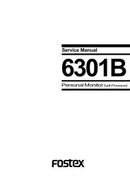
Names and Functions<br />
10 9 8 7 6 5 4 3 2 1<br />
WORD<br />
IN<br />
OUT<br />
75 <br />
75<br />
IN<br />
VIDEO<br />
THRU<br />
IN<br />
OUT<br />
IN<br />
TIME CODE<br />
OUT<br />
ON<br />
OFF<br />
ON<br />
OFF<br />
1. TIME CODE OUT connector (Connector: RCA pin jack - unbalanced)<br />
Time code (LTC) converted from A-TIME on the tape or IEC time code is<br />
output here.<br />
2. TIME CODE IN connector (Connector: RCA pin jack - unbalanced)<br />
External time code (LTC) is input here.<br />
Because this connector is the switching type, if it is used in parallel with<br />
the balanced connector (XLR), priority is given to the unbalanced (RCA)<br />
connector.<br />
3. TIME CODE OUT connector (Connector: XLR-3-32 type - balanced)<br />
Time code (LTC) converted from A-TIME on the tape or IEC time code is<br />
output here.<br />
4. TIME CODE IN connector (Connector: XLR-3-31 type - balanced)<br />
External time code (LTC) is input here.<br />
If this is used in parallel with the unbalanced (RCA) connector, the RCA<br />
type will be given priority and thus this connector will not function.<br />
5. VIDEO THRU connector (Connector: BNC type)<br />
The external video sync signal is input here when synchronizing with the<br />
video sync signal.<br />
6. VIDEO IN connector (Connector: BNC type)<br />
The external video sync signal is input here when synchronizing with the<br />
video sync signal.<br />
7. VIDEO IN terminating switch (75 ON/OFF)<br />
Termination of the VIDEO IN signal is switched ON or OFF but is normally<br />
switched ON.<br />
If a multiple connection is made via VIDEO THRU, then the last equipment<br />
only is switched ON and others switched OFF.<br />
6
Model 8335 (TC/SYNC card) <strong>Owner's</strong> <strong>Manual</strong><br />
8. WORD OUT connector (Connector: BNC type)<br />
Word sync signals are output here.<br />
When synchronizing with an external signal, word sync signals in sync<br />
with the external sync signal is output here.<br />
9. WORD IN connector (Connector: BNC type)<br />
The external word sync signal is input here when synchronizing with the<br />
word sync signal.<br />
10. WORD IN terminating switch (75 ON/OFF)<br />
Termination of the WORD IN signal is switched ON or OFF but is normally<br />
switched ON.<br />
7
Model 8335 (TC/SYNC card) <strong>Owner's</strong> <strong>Manual</strong><br />
Changes in D-15 functions and new SETUP menu items<br />
There will be some changes in the displays and key functions by installing<br />
the 8335 in the D-15 Furthermore, SETUP mode menu items heretofore not<br />
effective will now be effective.<br />
The content of these changes and now effective functions only will be<br />
explained here. Therefore, in regards to other functions, please refer to the<br />
D-15 Owners <strong>Manual</strong>.<br />
Content of changes<br />
1. TC on tape will be shown in the FL display!<br />
2. External time code (LTC) input will be displayed as the Reference (REF<br />
TC)!<br />
Due to these changes in above 1. and 2., the display content will be different<br />
as a result of the D-15 DISP TIME key operation.<br />
[Display switching by the DISP TIME key without 8335]<br />
A-time<br />
DATE<br />
[Display switching by the DISP TIME key with 8335]<br />
A-time TC (*1) or A-Time TC (*2) DATE REF TC (*3)<br />
(*1) TC Displays IEC time code figures recorded on tape.<br />
(*2) A-time TC Displays the resulting time code figures when A-time recorded on the<br />
tape is converted to time codes.<br />
(*3) REF TC Taking the externally input time code as a Reference, it is displayed as<br />
follows:<br />
: When indicating 1h:34m:28s:15f, frame rate = 24<br />
H M S F<br />
Other frame rate figures will be displayed as shown below:<br />
Type of TC<br />
Display<br />
24 (FILM) 24<br />
25 (EBU) 25<br />
30 or 29.97 drop frame (SMPTE) 30D or 29D<br />
30 or 29.97 nondrop frame (SMPTE) 30N or 29N<br />
8
Model 8335 (TC/SYNC card) <strong>Owner's</strong> <strong>Manual</strong><br />
3. Input monitor of audio/time code is possible!<br />
Input monitoring of audio and time code is possible by pressing the D-15<br />
[INPUT MONITOR] key.<br />
However, if audio data is being read into the RAM under the INSTANT<br />
START mode, input monitoring will be switched OFF automatically.<br />
Refer to page [14] of the D-15 <strong>Owner's</strong> <strong>Manual</strong> on judging input monitor<br />
conditions by the INPUT MONITOR LED.<br />
<br />
If it is desired to confirm the time code time which is being input,<br />
change to the "REF TC" display by pressing the [DISP TIME] key so that<br />
the time code figure being input can be confirmed.<br />
9
Model 8335 (TC/SYNC card) <strong>Owner's</strong> <strong>Manual</strong><br />
Changes and the new effective SETUP menu<br />
Together with changes in the SETUP menu "Version display function" by<br />
installation of 8335, the following 9 item menu can be setup.<br />
[Menu changed of display function]<br />
* Version display function (vErSion 001-chk)<br />
[New menu possible of setup]<br />
* Setup of the playback time code format (rEProtc 401 -***)<br />
* Frame rate setup of playback time code (FrAME 402 -***)<br />
* Time code output ON/OFF setup at pause (PAUStc 403 -***)<br />
* Setup of time code output at fast winding (Windtc 404 -***)<br />
* Setup of the event start mode by REF TC (rEFPLY 405 -***)<br />
* Setup of the time code to be recorded (rECFrAM 411 -***)<br />
* Setup of the CHASE operation mode (CASEMod 501 -***)<br />
* Setup of the lock window (LockWind 502 -***)<br />
* Setup of the external clock (ExtCLK 503 -***)<br />
1. Version display function [vE r Si on 001 -chk]<br />
In addition to the D-15 version/date, the version/date of 8335 that is installed<br />
can be confirmed.<br />
After simultaneously pressing [0] and [1] of the [numerical keypad] to enter<br />
the SETUP mode, select the [vErSion 001 -chk] menu by rotating the [JOG] dial<br />
and press the [EXECUTE/YES] key (It will change to the [D-15 version] display).<br />
Successively, if the [JOG] dial is rotated clockwise, it will alternately be<br />
displayed as follows in this order, and the order will be reversed when rotated<br />
counter clockwise.<br />
D-15 version<br />
8335 version<br />
D-15 date<br />
8335 date<br />
10
Model 8335 (TC/SYNC card) <strong>Owner's</strong> <strong>Manual</strong><br />
2. Setup of the playback time code format [rE Pr o tc 401 -***]<br />
The original time data to be converted to time code (LTC) and output is<br />
selected by this menu. Time data can be selected and setup from three types<br />
- "IEC AUTO," "IEC MANUAL" and "A-time."<br />
After entering the SETUP mode, rotate the [JOG] dial, select the [rEProtc 401<br />
-***] menu, and press the [EXECUTE/SET] key. Then, after rotating the [JOG]<br />
dial CW and CCW to select the desired time data, press the [EXECUTE/SET]<br />
key again to set it up (* is the initial setting).<br />
This setup content will be held even though power is switched OFF.<br />
Functional note Menu No. Setup No. Functional content<br />
IEC AUto 401 000(*) Converted to LTC from IEC time code.<br />
Frame rate will be "Auto."<br />
IEC MANU 401 001 Converted to LTC from IEC time code.<br />
Frame rate is setup by the next item<br />
"402 -***."<br />
A-time 401 002 Converted to LTC from A-TIME.<br />
Frame rate is setup by "402 -***."<br />
If "401-000" (IEC AUTO) is selected, it will be output automatically in<br />
the same frame rate as at recording regardless to the frame rate setup<br />
by the next item "Frame 402 -***."<br />
3. Frame rate setup of playback time code [Fr A ME 402 -***]<br />
When the original time data to be converted is set in "401 -001" or "401 -<br />
002" and played back by converting A-TIME or IEC time code to LTC, the<br />
frame rate, of the time code to be played back, can be randomly setup.<br />
Frame rates can be selected can be selected from the following six types.<br />
Should the time data be set in "401 -000" (IEC AUTO), this setting will be<br />
ineffective and will be output automatically in the frame rate that was<br />
recording.<br />
After entering the SETUP mode, rotate the [JOG] dial, select the [FrAME 402 -<br />
***] menu, and press the [EXECUTE/SET] key. Then, after rotating the [JOG]<br />
dial CW and CCW to select the desired frame rate, press the [EXECUTE/SET]<br />
key again (* is the initial setting).<br />
This setup content will be held even though power is switched OFF.<br />
Functional note Menu No. Setup No. Functional content<br />
Fr 24 402 000 24 frames<br />
Fr 25 402 001 (*) 25 frames<br />
Fr 29.97dF 402 002 29.97 drop frame<br />
Fr 29.97 402 003 29.97 non drop frame<br />
Fr 30 402 004 30 non drop frame<br />
Fr 30 dF 402 005 30 drop frame<br />
11
Model 8335 (TC/SYNC card) <strong>Owner's</strong> <strong>Manual</strong><br />
4. Time code output ON/OFF setup at pause [PA US tc 403 -***]<br />
Whether time code should be output or not in the PAUSE mode of D-15 is<br />
selected by this menu.<br />
After entering the SETUP mode, rotate the [JOG] dial, select the [PAUStc 403<br />
-***] menu, and press the [EXECUTE/SET] key. Then, after rotating the [JOG]<br />
dial CW and CCW to select the desired frame rate, press the [EXECUTE/SET]<br />
key again (* is the initial setting).<br />
This setup content will be held even though power is switched OFF.<br />
Functional note Menu No. Setup No. Functional content<br />
OFF 403 000 (*) PAUSE TC OFF (TC not output)<br />
ON 403 001 PAUSE TC ON (The read out time code<br />
is repeatedly out put in complete units of<br />
hour, minute, second and frame)<br />
5. Setup of time code output at fast winding [Wi nd tc 404 -***]<br />
Whether time code should be output or not in the fast wind mode of F FWD/<br />
REWIND of D-15 is selected by this menu.<br />
After entering the SETUP mode, rotate the [JOG] dial, select the [Windtc 404 -<br />
***] menu, and press the [EXECUTE/SET] key. Then, after rotating the [JOG]<br />
dial CW and CCW to select the desired frame rate, press the [EXECUTE/SET]<br />
key again (* is the initial setting).<br />
This setup content will be held even though power is switched OFF.<br />
Functional note Menu No. Setup No. Functional content<br />
1 Fr AM 404 000 (*) The read out time code is output in<br />
complete units of hour, minute, second<br />
and frame units.<br />
5 Fr AM 404 001 The read out time code in complete units<br />
of hour, minute, second and frame, and<br />
in addition four frames are pseudo<br />
attached for a total of 5 frames in the<br />
positive direction are converted to a<br />
continuous time code and output.<br />
Stop 404 002 Time code will not be output in other than<br />
the PLAY and REC modes.<br />
12
Model 8335 (TC/SYNC card) <strong>Owner's</strong> <strong>Manual</strong><br />
6. Setup of the event start mode by REF TC [rE FP LY 405 -***]<br />
When the D-15 is in the STOP or PAUSE mode, whether D-15 should event<br />
start (in PLAY mode) automatically or not when the time of the external time<br />
code (REFERENCE TC) that is input and the time setup in the D-15 memory<br />
[00] coincide, is selected from this menu.<br />
The event start mode can be selected from 3 different types - "oncE," "EVEry"<br />
and "oFF." If the D-15 GPI ON/OFF switch is "ON," "EVENT 0" is simultaneously<br />
output from the GPI OUT connector.<br />
After entering the SETUP mode, rotate the [JOG] dial, select the [rEFPLY 405<br />
-***] menu, and press the [EXECUTE/SET] key. Then, after rotating the [JOG]<br />
dial CW and CCW to select the desired frame rate, press the [EXECUTE/SET]<br />
key again (* is the initial setting).<br />
This setup content will return to the initial setting when power is switched<br />
OFF or after completion of the "oncE" mode.<br />
Functional note Menu No. Setup No. Functional content<br />
oFF 405 000 (*) It will not event start by ignoring the REF<br />
TC time.<br />
oncE 405 001 Functions only under the positive direction<br />
one time speed time code and will execute<br />
event start once.<br />
EVEry 405 002 Functions only under the positive direction<br />
one time speed time code and will<br />
repeatedly execute event start.<br />
If the event start mode is set to "oncE" or "EVEry," [REF] in the REF TC<br />
display will blink to indicate that it is in the event start mode.<br />
7. Setup of time code to be recorded [rE C Fr AM 411 -***]<br />
When either 9.97fps or 30fps external time code is to be input and recorded<br />
or when executing time code CHASE, this menu selects the frame rate which<br />
matches the external time code that is input. Either 29.97fps or 30fps is<br />
selected for the frame rate. However, should 24fps or 25fps time codes be<br />
input, the D-15 will automatically acknowledge this.<br />
After entering the SETUP mode, rotate the [JOG] dial, select the [rECFrAM 411<br />
-***] menu, and press the [EXECUTE/SET] key. Then, after rotating the [JOG]<br />
dial CW and CCW to select the desired frame rate, press the [EXECUTE/SET]<br />
key again (* is the initial setting).<br />
This setup content will be held even if the power is switched OFF.<br />
Functional note Menu No. Setup No. Functional content<br />
Fr 29.97 411 000 (*) The 29.97fps time code is selected.<br />
Fr 30 411 001 The 30fps time code is selected.<br />
13
Model 8335 (TC/SYNC card) <strong>Owner's</strong> <strong>Manual</strong><br />
8. Setup of the CHASE operation mode [CH SE M od 501 -***]<br />
The mode for locking (chase locking) D-15 to the external time code is selected<br />
by this menu. Operating modes can be selected from "oncE," "Cont" or<br />
"FrAME."<br />
After entering the SETUP mode, rotate the [JOG] dial, select the [CHSEMod<br />
501 -***] menu, and press the [EXECUTE/SET] key. Then, after rotating the<br />
[JOG] dial CW and CCW to select the desired frame rate, press the [EXECUTE/<br />
SET] key again (* is the initial setting).<br />
This setup content will be held even if the power is switched OFF.<br />
Functional note Menu No. Setup No. Functional content<br />
oncE 501 000 (*) After CHASE ON of D-15, chase is ended<br />
upon locking once on REF TC, then D-15<br />
will free run. Also, even if lock is<br />
disengaged, it will not enter chase again.<br />
Cont 501 001 After CHASE ON of D-15, it will lock onto<br />
REF TC, then will free run.<br />
If lock is disengaged, it will automatically<br />
chase again.<br />
FrAME 501 002 After CHASE ON of D-15, it will lock on to<br />
REF TC and frame sync playback<br />
executed at a sufficiently low fluctuation<br />
variable speed playback on the hearing<br />
characteristics such that it will remain<br />
locked (Refer to ) .<br />
Should lock be disengaged, it will automatically<br />
chase again.<br />
When the audio sampling clock and the time code clock do not match,<br />
the lock is apt to become disengaged if the transport is run for a long<br />
time. In such a case, use the above "FrAME (002)" mode.<br />
<br />
Permissible clock deviation between external time code and chaseable clock is<br />
about 0.1 %. Therefore, it will not function if clock deviation is larger than this.<br />
9. Setup of the lock window [Lo ck Wi nd 502 -***]<br />
The reference frame to determine the UNLOCK state subsequent to CHASE<br />
locking when selecting the "Cont (continue)" or "FrAME" CHASE operation<br />
mode to make the D-15 CHASE by the external time code, is selected by this<br />
menu. The reference frames can be setup within the one to 20 frame range<br />
in one frame units.<br />
After entering the SETUP mode, rotate the [JOG] dial, select the [LockWind<br />
502 -***] menu, and press the [EXECUTE/SET] key. Then, after rotating the<br />
[JOG] dial CW and CCW to select the desired frame rate, press the [EXECUTE/<br />
SET] key again (* is the initial setting).<br />
This setup content will be held even if the power is switched OFF.<br />
Functional note Menu No. Setup No. Functional content<br />
1 FrAM 502 000 The 1~20 frames can be set in one frame<br />
steps.<br />
20 FrAM 502 020 (*) "010" = 10 frames.<br />
14
Model 8335 (TC/SYNC card) <strong>Owner's</strong> <strong>Manual</strong><br />
10. Setup of the external clock [Ex tC LK 503 -***]<br />
The external sync signal to be used in phase modifying operation of the D-15<br />
with external equipment is selected by this menu. The external sync signal<br />
can be selected from three different types - "AES/Ebu," "Word" and "VidEo."<br />
After entering the SETUP mode, rotate the [JOG] dial, select the [ExtCLK 503<br />
-***] menu, and press the [EXECUTE/SET] key. Then, after rotating the [JOG]<br />
dial CW and CCW to select the desired frame rate, press the [EXECUTE/SET]<br />
key again (* is the initial setting).<br />
This setup content will be held even if the power is switched OFF.<br />
Functional note Menu No. Setup No. Functional content<br />
AES Ebu 503 000 Select the AES/EBU digital signal.<br />
Word 503 001 Select the word sync signal.<br />
VidEo 503 002 (*) Select the video sync signal.<br />
<br />
If external sync is not normal, the display [EXT CLOCK] will blink in warning.<br />
In such a case, check the connection and the setup content of the SETUP<br />
menu [ExtCLK 503 -***].<br />
<br />
When SETUP "503 -000 (AES/EBU)" is selected, use the XLR type connector to<br />
input the digital signal. Note that it will function if the OPTICAL IN connector<br />
is used.<br />
15
Model 8335 (TC/SYNC card) <strong>Owner's</strong> <strong>Manual</strong><br />
Additional Functions<br />
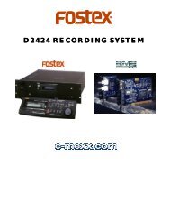
1. Recording the external time code (LTC)<br />
By installing this equipment in the D-15, external time codes (LTC) can be<br />
converted to IEC time codes (PRO R-TIME and PRO binary) and recorded in<br />
the sub code area while recording an audio signal.<br />
<br />
The D-15 with the Model 8335 installed cannot separately record audio and<br />
time codes. Therefore, it must be noted that if audio is inserted in a no sound<br />
recorded section, the time code of that section will be erased.<br />
Connection with external equipment<br />
In order to record time codes (LTC) during recording of audio signals, the<br />
8335 must be installed in the D-15 and external equipment connected to it<br />
as shown below.<br />
1. Connect the external equipment time code (LTC) output to the TIME CODE<br />
IN (XLR-3-31 type or RCA) connector of 8335 installed in D-15.<br />
<br />
If cables are connected to both XLR (balanced) and RCA (unbalanced)<br />
connectors, RCA will have priority and thus XLR cannot be used.<br />
If XLR must be used, do not plug anything in the RCA jack.<br />
2. Connect the audio input to the D-15 DIGITAL IN (or ANALOG IN) connector.<br />
Other audio equipment<br />
Time code generator<br />
LTC OUT<br />
WORD<br />
IN<br />
OUT<br />
IN<br />
VIDEO<br />
THRU<br />
IN<br />
OUT<br />
TIME CODE<br />
IN<br />
OUT<br />
75 75<br />
ON<br />
OFF<br />
ON<br />
OFF<br />
CH2<br />
CH1<br />
ANALOG INPUT<br />
CH2<br />
CH1<br />
ANALOG OUTPUT<br />
CAUTION<br />
UNBAL<br />
CH2<br />
CH1<br />
CH2<br />
CH1<br />
AC IN<br />
BAL<br />
IN<br />
OUT<br />
DIGITAL I/O<br />
IN<br />
OUT<br />
GPI IN<br />
GPI OUT<br />
37P-REMOTE<br />
D-15 + 8335<br />
AES/EBU OUT<br />
OPTICAL OUT<br />
Other DAT, etc.<br />
16
Model 8335 (TC/SYNC card) <strong>Owner's</strong> <strong>Manual</strong><br />
Recording<br />
1. Set the D-15 front panel [CLOCK] switch to [INT].<br />
When an external sync signal is input as a reference to record the time<br />
code in sync with this sync signal, set the [CLOCK] switch to [EXT] using<br />
the SETUP menu "503 -***.” Set it to the external clock identical with the<br />
external sync signal (Refer to below).<br />
Refer to page [15] for setup of the SETUP menu "503 -***."<br />
2. Setup the frame rate by the SETUP menu "411 -***" when time code to be<br />
recorded is 29.97fps or 30fps.<br />
When recording the 24fps, 25fps time codes, they will be automatically<br />
acknowledged and recorded regardless to the setting of the SETUP menu.<br />
The D-15 will automatically acknowledge 24 and 25fps time codes<br />
and record them but 29.97 and 30fps cannot be acknowledged.<br />
Therefore, if 29.97 or 30fps time codes are to be recorded, they<br />
must be specified by the SETUP menu "411 -***."<br />
Refer to page [13] for setting by the SETUP menu "411-***."<br />
3. Start the externally connected audio equipment and the TC generator.<br />
4. Start the D-15 in the record mode by pressing the [PLAY] button while<br />
pressing the [RECORD] button.<br />
5. After completing the recording, press the [STOP] button.<br />
<br />
Because ASSEMBLE recording only can be made by the D-15, if recording is<br />
temporarily stopped and then resumed, continuous time code cannot be<br />
recorded.<br />
<br />
If a recording is made with the [CLOCK] switch at [INT], a slight deviation of the<br />
clock will be created between the recorded time code (LTC) and the inner<br />
sampling clock.<br />
In such a case, synchronize the entire system by input of an external video sync<br />
signal as a reference to the VIDEO IN connector of this equipment.<br />
17
Model 8335 (TC/SYNC card) <strong>Owner's</strong> <strong>Manual</strong><br />
2. Conversion of A-TIME/IEC time code to LTC and output<br />
A-TIME or IEC time code recorded on the tape can be converted to LTC and<br />
output by installing the 8335 in the D-15. However, it must be noted that<br />
discontinuous or missing IEC time codes are not guaranteed).<br />
Procedures in converting A-TIME or IEC time code to LTC is explained here.<br />
Setup procedure<br />
1. Select time data to be converted.<br />
Time data to be converted to time code (LTC) is selected by SETUP menu<br />
"401 -***."<br />
Select "401 -002 (A-time)" to convert A-TIME and setup a random frame rate<br />
according to procedure [2] below, in regards to SETUP menu "401 -***."<br />
On the other hand, select either "401 -000 (IEC AUTO)" or "401-001 (IEC<br />
MANUAL)" to convert IEC time code.<br />
If "401-000 (IEC AUTO)" is selected, it will be output automatically, regardless<br />
to the frame rate setting, at a frame rate identical with that at recording.<br />
When "401-001 (IEC MANUAL)" is selected, it can be setup for a random<br />
frame rate by procedure [2] below, explaining SETUP menu "401 -***" (For<br />
example, even though the frame rate recorded on the tape is 25 frames, it<br />
can be set to 29.97 Drop Frame).<br />
Refer to page [11] for setup of SETUP menu "401-***."<br />
When A-TIME or IEC time code is converted and output, the time code<br />
figure can be confirmed by switching to the TC display with the<br />
[DISP TIME] key.<br />
Thus, the time code time can be confirmed by changing the display to<br />
show TC at which [A-TIME TC] will be shown during conversion of A-TIME,<br />
and [TC] when converting the IEC time code.<br />
2. Set frame rate of time code (LTC) to be output.<br />
When "401 -001 (IEC MANUAL)" or "401 -002 (A-TIME)" is selected and output<br />
as specified in above step [1], frame rate of the time code that is output<br />
can be setup. The frame rate can be set by the SETUP menu "402-***."<br />
Refer to page [11] for setup of SETUP menu "402-***."<br />
3. Setup the output type as necessary for time code outputs in the PAUSE<br />
and F FWD/REWIND modes.<br />
These can be setup by SETUP menus "403 -***" and "404 -***."<br />
Refer to page [12] on SETUP menus "403 -***" and "404 -***."<br />
18
1234567<br />
1234567<br />
1234567<br />
1234567<br />
1234567<br />
1234567<br />
1234567<br />
1234567<br />
1234567<br />
1234567<br />
1234567<br />
1234567<br />
Model 8335 (TC/SYNC card) <strong>Owner's</strong> <strong>Manual</strong><br />
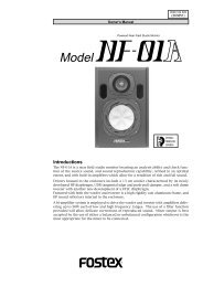
3. Chase synchronizing by external TC (Playback only)<br />
This function is for playing back tape in sync with externally input time<br />
codes which is possible when external time code is input to the TIME CODE<br />
IN (XLR or RCA) of the 8335 installed in the D-15, and then switching "ON"<br />
(by pressing the D-15 front panel CHASE key) the CHASE mode which is<br />
activated by installing of the 8335.<br />
<br />
Time code CHASE is executed at playback only and recording cannot be<br />
executed.<br />
Interconnections<br />
As an example, a D-15 installed with the 8335 is connected as the slave and<br />
a VTR as the master are interconnected as shown in the schematic.<br />
In this example, time codes recorded in the VTR is input to D-15+8335, then<br />
the audio signal is played back by letting the VTR chase it.<br />
In this operation, the video sync signal or word sync signal from the VTR is<br />
input as a reference by the connections shown in the schematic.<br />
Model 6301B<br />
Model 6301B<br />
Analog audio mixer<br />
Audio signal<br />
WORD<br />
IN<br />
OUT<br />
IN<br />
VIDEO<br />
THRU<br />
IN<br />
OUT<br />
TIME CODE<br />
IN<br />
OUT<br />
75 75<br />
ON<br />
OFF<br />
ON<br />
OFF<br />
CH2<br />
CH1<br />
ANALOG INPUT<br />
CH2<br />
CH1<br />
ANALOG OUTPUT<br />
CAUTION<br />
UNBAL<br />
CH2<br />
CH1<br />
CH2<br />
CH1<br />
AC IN<br />
BAL<br />
IN<br />
OUT<br />
DIGITAL I/O<br />
IN<br />
OUT<br />
GPI IN<br />
GPI OUT<br />
37P-REMOTE<br />
VIDEO SYNC signal<br />
TC<br />
D-15 + 8335<br />
WORD SYNC signal<br />
VTR<br />
19
Model 8335 (TC/SYNC card) <strong>Owner's</strong> <strong>Manual</strong><br />
Settings Prior to Operation<br />
Setup the following items prior to actual operation.<br />
1. Set the D-15 front panel [CLOCK] switch to [EXT].<br />
2. Set the 8335 external clock to match that of the master.<br />
[EXT CLOCK] will be shown in the display.<br />
Set the external clock by the SETUP menu "503-***."<br />
Refer to page [15] on setup of the SETUP menu "503-***."<br />
3. Setup CHASE mode of 8335.<br />
Select and setup the CHASE operation mode suitable for your application<br />
from among "501 -000 (ONCE)," "501 -001 (CONTINUE)" or "501 -002 (FRAME)"<br />
in the SETUP menu "501 -***."<br />
Refer to page [14] on setup of the SETUP menu "501-***."<br />
4. Setup LOCK WINDOW when "501 -001 (CONT)" or "501 -002 (FrAME)" is selected<br />
for the CHASE mode.<br />
Setup the reference frame by the SETUP menu "502 -***" to determine the<br />
UNLOCK state after entering the CHASE LOCK mode.<br />
Refer to page [14] on setup of the SETUP menu "502-***."<br />
5. Setup the CHASE OFFSET figure.<br />
If the CHASE OFFSET figure is randomly set, the D-15 will chase by<br />
maintaining the interval for the time setup by CHASE OFFSET.<br />
CHASE OFFSET can be setup with the OFFSET data edit mode by pressing<br />
the D-15 front panel [OFFSET] key, then the [QUIT/RCL] key.<br />
Refer to page [26] for details on editing the OFFSET figure.<br />
Executing CHASE SYNC<br />
After finishing the previous "Settings Prior to Operation," chase sync is<br />
executed.<br />
1. Start playback of the master machine (VTR in this case).<br />
2. Switch on the D-15 front panel [CHASE] key (CHASE LED blinks).<br />
By using the playback time code of D-15 (slave), it will start playback in<br />
chase lock with the master machine time code.<br />
When the slave machine is chase locked to the master machine, [CHASE<br />
LOCK] will appear in the display and, at the same time, CHASE LED will<br />
change from blinking to constant lighting.<br />
3. To stop the chase operation, press the [CHASE] key again (CHASE LED will<br />
be extinguished).<br />
20
Model 8335 (TC/SYNC card) <strong>Owner's</strong> <strong>Manual</strong><br />
4. Phase Modified Operation by External Sync Signal<br />
Even though time code is not recorded on the tape, the D-15 can be locked<br />
onto external sync signals such as WORD IN, VIDEO IN, AES/EBU digital signals<br />
in phase modified operation.<br />
Interconnections<br />
As shown in the schematic, external sync signals are input to either WORD<br />
IN, VIDEO IN or AES/EBU IN which matches the output of external equipment.<br />
External equipment<br />
External equipment<br />
WORD SYNC signal<br />
VIDEO SYNC signal<br />
WORD<br />
IN<br />
OUT<br />
IN<br />
VIDEO<br />
THRU<br />
IN<br />
OUT<br />
TIME CODE<br />
IN<br />
OUT<br />
75 75<br />
ON<br />
OFF<br />
ON<br />
OFF<br />
CH2<br />
CH1<br />
ANALOG INPUT<br />
CH2<br />
CH1<br />
ANALOG OUTPUT<br />
CAUTION<br />
UNBAL<br />
CH2<br />
CH1<br />
CH2<br />
CH1<br />
AC IN<br />
BAL<br />
IN<br />
OUT<br />
DIGITAL I/O<br />
IN<br />
OUT<br />
GPI IN<br />
GPI OUT<br />
37P-REMOTE<br />
AES/EBU signal<br />
External equipment<br />
Settings Prior to Phase Modified Operation<br />
Any one of the following setups are made depending on type of external<br />
sync signal that is to be input.<br />
<br />
1. Set the D-15 front panel [CLOCK] switch to [EXT].<br />
2. Select "503-001 (WORD)" by the SETUP mode "503-***" (Selecting the external<br />
sync signal).<br />
When the external sync signal is correctly input, [EXT CLOCK] will be lit in<br />
the display.<br />
3. Set FS to the same FS of the external sync signal which is input.<br />
Set to [44.1kHz] or [48kHz] with the D-15 front panel [SAMPLING FREQ]<br />
switch.<br />
21
Model 8335 (TC/SYNC card) <strong>Owner's</strong> <strong>Manual</strong><br />
<br />
1. Set the D-15 front panel [CLOCK] switch to [EXT].<br />
2. Select "503 -002 (VIDEO)" by the SETUP mode "503 -***" (Selecting the external<br />
sync signal).<br />
When the external sync signal is correctly input, [EXT CLOCK] will be lit in<br />
the display.<br />
<br />
1. Set the D-15 front panel [CLOCK] switch to [EXT].<br />
2. Select "503 -003 (AES/EBU)" by the SETUP mode "503 -***" (Selecting the<br />
external sync signal).<br />
When the external sync signal is correctly input, [EXT CLOCK] will be lit in<br />
the display.<br />
3. Set FS to the same FS of the external sync signal which is input.<br />
Set to [44.1kHz] or [48kHz] with the D-15 front panel [SAMPLING FREQ]<br />
switch.<br />
Refer to page [15] for setup of the SETUP menu "503-***."<br />
22
ON<br />
ON<br />
OFF<br />
OFF<br />
CH2<br />
IN<br />
CH2<br />
IN<br />
IN<br />
IN<br />
WORD<br />
WORD<br />
OUT<br />
CH1<br />
OUT<br />
OUT<br />
CH1<br />
OUT<br />
BAL<br />
BAL<br />
UNBAL<br />
IN<br />
UNBAL<br />
IN<br />
ON<br />
ANALOG INPUT<br />
CH2<br />
DIGITAL I/O<br />
OUT<br />
ON<br />
OFF<br />
CH1<br />
ANALOG INPUT<br />
CH2<br />
DIGITAL I/O<br />
OUT<br />
OFF<br />
CH1<br />
IN<br />
IN<br />
VIDEO<br />
CH2<br />
VIDEO<br />
CH2<br />
THRU<br />
GPI IN<br />
CH1<br />
THRU<br />
GPI IN<br />
CH1<br />
GPI OUT<br />
GPI OUT<br />
CH2<br />
CH2<br />
IN<br />
IN<br />
37P-REMOTE<br />
37P-REMOTE<br />
OUT<br />
OUT<br />
CH1<br />
CH1<br />
IN<br />
TIME CODE<br />
OUT<br />
ANALOG OUTPUT<br />
IN<br />
TIME CODE<br />
OUT<br />
ANALOG OUTPUT<br />
AC IN<br />
AC IN<br />
Model 8335 (TC/SYNC card) <strong>Owner's</strong> <strong>Manual</strong><br />
5. Using the Event Start Mode<br />
The event start mode is one of the additional functions after installing the<br />
8335 in the D-15. With this function, when the D-15 is in the STOP or PAUSE<br />
mode, it will automatically playback when an external time code is input to<br />
a D-15 installed with an 8335, and becomes the same as the time previously<br />
set in the D-15 memory [00]. That is, the same as the data used for AUTO<br />
REC in which the TC figure is previously edited and stored in memory [00].<br />
If the D-15 front panel [GPI] switch had been switched [ON] prior to above<br />
operation, [EVENT 0] will be simultaneously output from the GPI OUT<br />
connector.<br />
Use this function for situations such as simultaneously starting two D-15's<br />
connected to external equipment at a randomly set time.<br />
Interconnections<br />
In the example shown in the schematic, a D-15 installed with the 8335 is<br />
connected to a VTR and time code from the VTR is input to TIME CODE IN of<br />
the first D-15. Then, the first D-15 GPI OUT is connected to the 2nd D-15 GPI<br />
IN (or other external equipment containing GPI IN).<br />
Furthermore, to guarantee perfect sync of the two D-15's, AES/EBU signal<br />
lines from the first D-15 to the second D-15 should be provided (Refer to<br />
schematic below).<br />
External equipment<br />
# 1<br />
75 75<br />
CAUTION<br />
# 2<br />
75 75<br />
CAUTION<br />
Audio mixer<br />
23
Model 8335 (TC/SYNC card) <strong>Owner's</strong> <strong>Manual</strong><br />
Setup of the First D-15<br />
1. Switch [ON] the front panel [GPI] switch.<br />
2. Switch [ON] the event start mode by the SETUP mode.<br />
Select and setup either "001 (oncE)" or "002 (EVEry)" by the SETUP menu<br />
"405 -***." Simultaneous with setup of the SETUP menu "405 -***" to either<br />
one of these, [REF] will blink in the display to indicate that the event start<br />
mode is [ON].<br />
<br />
When "001 (oncE)" is selected by the SETUP menu "405-***," event start is<br />
executed once and simultaneously switch to "000" (OFF) and [REF] will be<br />
extinguished. When power is switched off, the setup content will not be held<br />
but switch to "000" (OFF).<br />
Refer to page [13] for details on setup of SETUP menu "405-***."<br />
3. Set recording to head of playback.<br />
4. Press the [INSTANT START] key to switch [ON] the INSTANT START mode.<br />
INSTANT START can then be executed from head of recording.<br />
Setup of the 2nd D-15<br />
1. Switch [ON] the front panel [GPI] switch.<br />
2. Switch [ON] the INSTANT START mode.<br />
3. Set the external clock to "503-000 (AES/EBU)" by the SETUP menu "503-***."<br />
4. Set recording to head of playback.<br />
Refer to page [15] for details on the SETUP menu "503-***."<br />
Setup of Memory [00]<br />
The time figure identical to the reference time code from which event is to<br />
be started is edited and stored in memory [00] of the first D-15.<br />
Although memory [00] is setup using by the same procedure as for executing<br />
the AUTO REC mode, it can also be set by TC time in addition to A-TIME by<br />
installing 8335. In order to setup by A-TIME, change the display to A-TIME<br />
and if TC time is to be setup, change to the TC display.<br />
Refer to [AUTO REC mode] of the D-15 Owners <strong>Manual</strong> for setup method of memory [00].<br />
24
Model 8335 (TC/SYNC card) <strong>Owner's</strong> <strong>Manual</strong><br />
<br />
When editing to the same time as the external time code, either A-TIME or TC<br />
can be used to match down to second units.<br />
However, if it is to be set in frame units with external time code, frame errors<br />
will be created and thus accurate event start cannot always be expected.<br />
Therefore, in order to operate the recorder more accurately (down to frame<br />
units), use the following method in setup of memory [00].<br />
1. Set to "IEC MANU" by the SETUP menu "401-***" and likewise use<br />
SETUP menu "402-***" to set the frame rate same as in the external time<br />
code.<br />
2. Change the display to [TC].<br />
Executing Event Start<br />
1. Start playback of the external equipment.<br />
At the instant the external time code time and the time set in memory [00]<br />
of the first D-15 becomes the same, the D-15 in standby in the STOP or<br />
PAUSE mode will start to playback. At the same time, [EVENT 0] is output<br />
from GPI OUT of the first D-15 and the second D-15 will start playback at<br />
the same timing.<br />
6. MEM NO Locate / TIME Locate by TC Time<br />
By installing the 8335, in addition to the time of A-TIME, memory by TC<br />
time, MEM NO locate and time locate then becomes possible.<br />
The actual operating method is the same as when the 8335 is not installed<br />
but before operation, the display must be changed to [TC] by the [DISP TIME]<br />
key. For operating methods of memory/locate, refer to the D-15 Owners<br />
<strong>Manual</strong>.<br />
<br />
To execute memory/locate with the TC time, the display must always be<br />
changed to TC. For example, when attempting to locate to the MEM NO stored<br />
in TC time in the memory, if this is executed while A-TIME is displayed, the TC<br />
time for locating will be by the A-TIME and thus be located by this time.<br />
25
Model 8335 (TC/SYNC card) <strong>Owner's</strong> <strong>Manual</strong><br />
7. Editing the OFFSET Figure<br />
By installing the 8335, it will then be possible to edit memory data of TC<br />
time aside from A-TIME. The same method as when an 8335 is not installed<br />
can be used by changing the display to TC.<br />
In addition, editing CHASE OFFSET is now possible as a new function.<br />
When executing CHASE operation in sync with external time codes, a certain<br />
amount of time difference (CHASE OFFSET TIME) can be set between two<br />
time codes functioning in synchronization.<br />
If this OFFSET figure is setup, when the slave D-15 starts the CHASE operation,<br />
it can be synchronized with the external time code while maintaining an<br />
interval equal to the CHASE OFFSET time. The operating method below, as<br />
explained by "Chase Synchronizing" on page 19, is explained in the situation<br />
of inputing an external time code to the D-15.<br />
Editing Method<br />
1. Press once the D-15 front panel [OFFSET] key.<br />
When the key is pressed, time difference between the presently input<br />
external time code and time code on the tape, and the frame rate is<br />
displayed (Example below shows that the present OFFSET is 00: 01: 18: 03:<br />
84 and frame rate is 25).<br />
OFFSET<br />
H M S F<br />
2. Next, press the [QUIT/RCL] key.<br />
It is entered in the OFFSET data edit mode and [H] will blink as shown in<br />
the schematic.(Example: OFFSET is set to [00:00:00:00:00])<br />
Blink<br />
OFFSET<br />
H M S F<br />
3. Input the desired OFFSET data.<br />
A new number can be input at the blinking digit.<br />
The blinking digit can be shifted to right or left by the [SHUTTLE] dial and<br />
numbers input at the blinking digit with the [JOG] dial or the [10] key<br />
(numerical keypad).<br />
Input by JOG<br />
Input by [10] key<br />
When rotated clockwise at the blinking digit other than [H], it will<br />
count up, and count down in the counter clockwise rotation.<br />
At the instant two numbers are input at the blinking digit, the<br />
blinking digit will shift to the right.<br />
26
Model 8335 (TC/SYNC card) <strong>Owner's</strong> <strong>Manual</strong><br />
4. After input of a new OFFSET data, press the [EXECUTE/SET] key.<br />
Simultaneous with fixing the input data as the CHASE OFFSET figure, the<br />
D-15 will be released from the edit mode and return to the OFFSET display.<br />
Depending on the CHASE OFFSET setup content, D-15 will operate as follows:<br />
1. If OFFSET is set to (+) time, the D-15 will sync ahead of the master<br />
machine time code by the OFFSET amount.<br />
2. If OFFSET is set to (-) time, the D-15 will sync behind of the master<br />
machine time code by the OFFSET amount.<br />
3. If OFFSET is set to (00:00:00:00:00) time, the D-15 will catch up with<br />
the master machine and sync at the same time as the time code.<br />
27
Model 8335 (TC/SYNC card) <strong>Owner's</strong> <strong>Manual</strong><br />
Major Specifications<br />
TIME CODE INPUTS/OUTPUTS<br />
Format<br />
<br />
Connector<br />
Standard input level<br />
Minimum input level<br />
Input impedance<br />
<br />
Connector<br />
Standard input level<br />
Minimum input level<br />
Input impedance<br />
<br />
Connector<br />
Standard output level<br />
Load impedance<br />
<br />
Connector<br />
Standard output level<br />
Load impedance<br />
: SMPTE/EBU<br />
: XLR-3-31 type (x1)<br />
: 2V p-p<br />
: 0.25V p-p<br />
: 20k or more<br />
: RCA pin (x1)<br />
: 1V p-p<br />
: 0.25V p-p<br />
: 10k or more<br />
: XLR-3-32 type (x1)<br />
: 2V p-p<br />
: 600 or more<br />
: RCA pin (x1)<br />
: 1V p-p<br />
: 600 or more<br />
VIDEO IN<br />
Connector<br />
Format<br />
Standard input level<br />
Input impedance<br />
: BNC type (x1)<br />
: Composite<br />
: 1V p-p<br />
: 75 (On/off by terminating switch)<br />
VIDEO THRU<br />
WORD IN<br />
WORD OUT<br />
Connector<br />
Standard output level<br />
Connector<br />
Standard input level<br />
Input impedance<br />
Connector<br />
Standard output level<br />
Load impedance<br />
: BNC type (x1)<br />
: Video input is directly output.<br />
: BNC type (x1)<br />
: TTL level<br />
: 75 (On/off by terminating switch)<br />
: BNC type (x1)<br />
: TTL level<br />
: 75 or more<br />
POWER SUPPLY : Supplied from D-15 (DC +5V, DC 15V)<br />
* Specifications and appearance of this product subject to change without notice.<br />
28
Model 8335 (TC/SYNC card) <strong>Owner's</strong> <strong>Manual</strong><br />
Declaration of EC Directive<br />
This equipment is compatible with the EMC Directive (89/336/EEC) - Directive<br />
on approximation of member nation's ordinance concerning the electromagnetic<br />
compatibility and with the Low Voltage Directive (73/23/EEC) - Directive on<br />
approximation of member nation's ordinance connecting electric equipment<br />
designed to be used within the specified voltage range.<br />
29
Model 8335 (TC/SYNC card) <strong>Owner's</strong> <strong>Manual</strong><br />
FOSTEX DISTRIBUTORS LIST IN EUROPE<br />
* Including non-EU countries (as of August, 2002)<br />
<br />
NAME: ATEC Audio-u. Videogeraete VertriebsgesmbH.<br />
ADD: Im Winkel 5, A-2325 Velm, Austria<br />
TEL: (+43) 2234-74004, FAX: (+43) 2234-74074<br />
<br />
NAME: EML Sound Industries NV<br />
ADD: Bijvennestraat 1A, B3500 Hasselt, Belgium<br />
TEL: (+32) 11-232355, FAX: (+32) 11-232172<br />
<br />
NAME: SC Sound ApS<br />
ADD: Malervej 2, DK-2630 Taastrup, Denmark<br />
TEL: (+45) 4399-8877, FAX: (+45) 4399-8077<br />
<br />
NAME: Noretron Oy Audio<br />
ADD: P. O. Box 22, FIN-02631 Espoo, Finland<br />
TEL: (+358) 9-5259330, FAX: (+358) 9-52593352<br />
<br />
NAME: Guillard Musiques<br />
ADD: ZAC de Folliouses, B. P. 609, Les Echets, 01706<br />
Miribel, France<br />
TEL: (+33) 472 26 27 00, FAX: (+33) 472 26 27 01<br />
<br />
NAME: Studiosound & Music GmbH<br />
ADD: Industriestrasse 20, D-35041 Marburg, F. R.<br />
Germany<br />
TEL: (+49) 6421-92510, FAX: (+49) 6421-925119<br />
<br />
NAME: Bon Studio S. A.<br />
ADD: 6 Zaimi Street, Exarchia, 106.83 Athens, Greece<br />
TEL: (+30) 1-3809605-8, 3302059<br />
FAX: (+30) 1-3845755<br />
<br />
NAME: I. D. elrf. electronic Ltd.<br />
ADD: Armula 38 108 Reykjavik, Iceland<br />
TEL: (+354) 588 5010, FAX: (+354) 588 5011<br />
<br />
NAME: IEMKE ROOS AUDIO B. V.<br />
ADD: Kuiperbergweg 20, 1101 AG Amsterdam, The<br />
Netherlands<br />
TEL: (+31) 20-697-2121, FAX: (+31) 20-697-4201<br />
<br />
NAME: Siv. Ing. Benum A/S<br />
ADD: P. O. Box 145 Vinderen, 0319 Oslo 3, Norway<br />
TEL: (+47) 22-139900, FAX: (+47) 22-148259<br />
<br />
NAME: Caius - Tecnologias Audio e Musica, Lda.<br />
ADD: Rua de Santa Catarina, 131 4000 Porto, Portugal<br />
TEL: (+351) 2-2086009/2001394<br />
FAX: (+351) 2-2054760/2087488<br />
<br />
NAME: Multitracker, S. A.<br />
ADD: C/Garcilaso No.9, Madrid 28010, Spain<br />
TEL: (+34) 91-4470700, 91-4470898<br />
FAX: (+34) 91-5930716<br />
<br />
NAME: TTS Scandinavia AB<br />
ADD: Kavallerivagen 24, 172 48 Sundbyberg, Sweden<br />
TEL: (+46) 8-59798000, FAX: (+46) 8-59798001<br />
<br />
NAME: Audio Bauer Pro AG<br />
ADD: Bernerstrasse-Nord 182, CH-8064 Zurich,<br />
Switzerland<br />
TEL: (+41) 1-4323230, FAX: (+41) 1-4326558<br />
<br />
NAME: SCV London<br />
ADD: 40 Chigwell Lane, Oakwood Hill Industrial<br />
Estate, Loughton, Essex IG10 3NY U. K.<br />
TEL: (+44) 020-8418-0778<br />
FAX: (+44) 020-8418-0624<br />
<br />
NAME: Proel S. p. A.<br />
ADD: Zona Via Alla Ruenia, 37/43 64027-Sant'Omero<br />
(Teramo), Italy<br />
TEL: (+39) 0861-81241, FAX: (+39) 0861-887862<br />
30