PD-606 Owners Manual - Fostex
PD-606 Owners Manual - Fostex
PD-606 Owners Manual - Fostex

You also want an ePaper? Increase the reach of your titles
YUMPU automatically turns print PDFs into web optimized ePapers that Google loves.
LOCATION RECORDER<br />
Model <strong>PD</strong><strong>606</strong><br />
Owner’s <strong>Manual</strong>
Safety Instructions/Table of contents<br />
CAUTION<br />
RISK OF ELECTRIC SHOCK<br />
DO NOT OPEN<br />
CAUTION: TO REDUCE THE RISK OF ELECTRIC SHOCK,<br />
DO NOT REMOVE COVER (OR BACK).<br />
NO USER - SERVICEABLE PARTS INSIDE.<br />
CAUTION:<br />
TO PREVENT ELECTRIC SHOCK, MATCH WIDE<br />
BLADE OF PLUG TO WIDE SLOT, FULLY INSERT.<br />
ATTENTION:<br />
POUR EVITER LES CHOCS ELECTRIQUES,<br />
INTRODUIRE LA LAME LA PLUS LARGE DE LA<br />
FICHE DANS LA BORNE CORRESPONDANTE DE<br />
LA PRISE ET POUSSER JUSQU' AU FOND.<br />
REFER SERVICING TO QUALIFIED SERVICE PERSONNEL.<br />
"WARNING"<br />
"TO REDUCE THE RISK OF FIRE OR ELECTRIC SHOCK,<br />
DO NOT EXPOSE THIS APPLIANCE TO RAIN OR<br />
MOISTURE."<br />
SAFETY INSTRUCTIONS<br />
1. Read Instructions - All the safety and operating instructions<br />
should be read before the appliance is operated.<br />
2. Retain Instructions - The safety and operating instructions<br />
should be retained for future reference.<br />
3. Heed Warnings - All warnings on the appliance and in the<br />
operating instructions should be adhered to.<br />
4. Follow Instructions - All operating and use instructions should<br />
be followed.<br />
5. Water and Moisture - The appliance should not be used near<br />
water - for example, near a bathtub, washbowl, kitchen sink,<br />
laundry tub, in a wet basement, or near a swimming pool, and<br />
the like.<br />
6. Carts and Stands - The appliance should be used only with a<br />
cart or stand that is recommended by the manufacturer.<br />
An appliance and cart combination should be moved with care.<br />
Quick stops, excessive force, and uneven surfaces may cause<br />
the appliance and cart combination to overturn.<br />
7. Wall or Ceiling Mounting - The appliance should be mounted<br />
to a wall or ceiling only as recommended by the manufacturer.<br />
8. Ventilation - The appliance should be situated so that its location<br />
or position dose not interfere with its proper ventilation.<br />
For example, the appliance should not be situated on a bed,<br />
sofa, rug, or similar surface that may block the ventilation<br />
openings; or, placed in a built-in installation, such as a bookcase<br />
or cabinet that may impede the flow of air through the ventilation<br />
openings.<br />
9. Heat - The appliance should be situated away from heat<br />
sources such as radiators, heat registers, stoves, or other<br />
appliances (including amplifiers) that produce heat.<br />
10. Power Sources - The appliance should be connected to a power<br />
supply only of the type described in the operating instructions<br />
or as marked on the appliance.<br />
11. Grounding or Polarization - The precautions that should be<br />
taken so that the grounding or polarization means of an<br />
appliance is not defeated.<br />
The lightning flash with arrowhead symbol, within an<br />
equilateral triangle, is intended to alert the user to<br />
the presence of uninsulated "dangerous voltage"<br />
within the product's enclosure that may be of sufficient<br />
magnitude to constitute a risk of electric shock to<br />
persons.<br />
The exclamation point within an equilateral triangle<br />
is intended to alert the user to the presence of<br />
important operating and maintenance (servicing)<br />
instructions in the literature accompanying the<br />
appliance.<br />
12. Power Cord Protection - Power supply cords should be routed<br />
so that they are not likely to be walked on or pinched by items<br />
placed upon or against them, paying particular attention to<br />
cords at plugs, convenience receptacles, and the point where<br />
they exit from the appliance.<br />
13. Cleaning - The appliance should be cleaned only with dry cloth.<br />
14. Nonuse Periods - The power cord of the appliance should be<br />
unplugged from the outlet when left unused for a long period<br />
of time.<br />
15. Object and Liquid Entry - Care should be taken so that objects<br />
do not fall and liquids are not spilled into the enclosure through<br />
openings.<br />
16. Damage Requiring Service - The appliance should be serviced<br />
by qualified service personnel when:<br />
A. The power supply cord or the plug has been damaged; or<br />
B. Objects have fallen, or liquid has been spilled into the<br />
appliance; or<br />
C. The appliance has been exposed to rain; or<br />
D. The appliance does not appear to operate normally or<br />
exhibits a marked change in performance; or<br />
E. The appliance has been dropped, or the enclosure damaged.<br />
17. Servicing - The user should not attempt to service the appliance<br />
beyond that described in the operating instructions.<br />
All other servicing should be referred to qualified service<br />
personnel.<br />
18. The appliance should be situated away from drops of water or<br />
spray of water.<br />
19. Objects containing liquid such as vase must not be put on the<br />
appliance.<br />
20. The appliance is not completely isolated from the power supply<br />
even if the power switch is at off position.<br />
21. Appliance shall not be exposed to dripping or splashing and<br />
no objects filled with liquids, such as vases, shall be placed on<br />
the appliance.<br />
22. Only use attachments/accessories specified by the<br />
manufacturer.<br />
23. An appliance with a protective earth terminal should be<br />
connected to a mains outlet with a protective earth connection.<br />
24. An appliance should be placed in a position where an AC plug/<br />
inlet can be easily pulled out by hand.<br />
25. Main plug is used as the disconnection device. It shall remain<br />
readily operable and should not be obstructed during intended<br />
use. To be completely disconnected the apparatus from supply<br />
mains, the mains plug of the apparatus shall be disconnected<br />
from the mains socket outlet completely.<br />
2 Location Recorder Model <strong>PD</strong><strong>606</strong>
Safety Instructions/Table of contents<br />
Important Safety Instructions<br />
1) Read these instructions.<br />
2) Keep these instructions.<br />
3) Heed all warnings.<br />
4) Follow all instructions.<br />
5) Do not use this apparatus near water.<br />
6) Clean only with dry cloth.<br />
11) Only use attachments/accessories<br />
specified by the manufacturer.<br />
12) Use only with the cart, stand, tripod,<br />
bracket, or table specified by the<br />
manufacturer, or sold with the apparatus.<br />
When a cart is used, use caution when<br />
moving the cart/apparatus combination<br />
to avoid injury from tip-over.<br />
7) Do not block any ventilation openings.<br />
Install in accordance with the<br />
manufacturer's instructions.<br />
8) Do not install near any heat sources such<br />
as radiators, heat registers, stoves, or<br />
other apparatus (including amplifiers) that<br />
produce heat.<br />
9) Do not defeat the safety purpose of the<br />
polarized or grounding-type plug.<br />
A polarized plug has two blades with one<br />
wider than the other. A grounding type<br />
plug has two blades and a third grounding<br />
prong. The wide blade or the third prong<br />
are provided for your safety.<br />
If the provided plug does not fit into your<br />
outlet, consult an electrician for<br />
replacement of the obsolete outlet.<br />
13) Unplug this apparatus during lightning<br />
storms or when unused for long periods<br />
of time.<br />
14) Refer all servicing to qualified service<br />
personnel. Servicing is required when the<br />
apparatus has been damaged in any<br />
way, such as power-supply cord or plug<br />
is damaged, liquid has been spilled or<br />
objects have fallen into the apparatus, the<br />
apparatus has been exposed to rain or<br />
moisture, does not operate normally, or<br />
has been dropped.<br />
10) Protect the power cord from being walked<br />
on or pinched particularly at plugs,<br />
convenience receptacles, and the point<br />
where they exit from the apparatus.<br />
Location Recorder Model <strong>PD</strong><strong>606</strong><br />
3
Safety Instructions/Table of contents<br />
Table of contents<br />
Introduction of this manual ................................................................................................................11<br />
Precautions ..........................................................................................................................................11<br />
Cautions for use ..................................................................................................................................13<br />
Precautions of installation .................................................................................................................13<br />
Chapter-1: Main features .....................................................................................15<br />
Main features and functions .........................................................................................................16<br />
What is in the box? .........................................................................................................................19<br />
<strong>PD</strong><strong>606</strong> options and related <strong>Fostex</strong> products .............................................................................19<br />
Chapter-2: Preparation before using the <strong>PD</strong><strong>606</strong> ..............................................21<br />
Preparation of power supply ........................................................................................................22<br />
Mounting the battery .....................................................................................................................23<br />
Important settings for using the battery .....................................................................................24<br />
Battery priority setting (essential when using more than one battery) ....................................24<br />
Low battery warning setting ............................................................................................................24<br />
Power supply priority setting (essential when using both [DC-IN] and a battery) ..................25<br />
Protector adjustment ........................................................................................................................25<br />
Saving the battery power ...............................................................................................................26<br />
Battery condition display ..............................................................................................................26<br />
Dismounting the battery ...............................................................................................................27<br />
Using [DC-IN] (Connecting the AC adaptor) ...............................................................................28<br />
Important settings for using [DC-IN] ...........................................................................................28<br />
Low battery warning setting ............................................................................................................28<br />
Power supply priority setting (essential when using both [DC-IN] and a battery) ..................28<br />
Turning on the power ....................................................................................................................29<br />
Display backlight and contrast .....................................................................................................30<br />
Turning on the display backlight .............................................................................................. ......30<br />
Adjusting the display contrast ........................................................................................................30<br />
Turning off the power ....................................................................................................................30<br />
Internal clock setting ...........................................................................................................................31<br />
Preparation of a DVD-RAM disk ........................................................................................................33<br />
Inserting a disk ................................................................................................................................33<br />
Initial format of a DVD-RAM disk .................................................................................................34<br />
Replacing the internal hard disk drive ..............................................................................................37<br />
4 Location Recorder Model <strong>PD</strong><strong>606</strong>
Safety Instructions/Table of contents<br />
Chapter-3: Names and functions .......................................................................39<br />
Left side panel (inputs/outputs) ........................................................................................................40<br />
Right side panel (inputs/outputs) ......................................................................................................42<br />
Front panel ...........................................................................................................................................45<br />
Top panel ..............................................................................................................................................53<br />
Rear panel .............................................................................................................................................55<br />
LCD display details .............................................................................................................................56<br />
Home screen ....................................................................................................................................56<br />
Time display .......................................................................................................................................56<br />
Status information ....................................................................................................................57<br />
File name/Next file name .........................................................................................................58<br />
Disk remaining ..........................................................................................................................58<br />
Current drive/file number ......................................................................................................58<br />
Protect icon ........................................................................................................................................58<br />
Screen examples ........................................................................................................................59<br />
MENU list screen ..........................................................................................................................59<br />
SYS SETUP menu screen ..............................................................................................................59<br />
BATTERY SETUP menu screen ...................................................................................................59<br />
TC SETUP menu screen ...............................................................................................................59<br />
DISK UTILITY menu screen ........................................................................................................59<br />
USB to PC menu screen ...............................................................................................................59<br />
EDIT EDL FILE menu screen .......................................................................................................60<br />
Audio file select screen ...............................................................................................................60<br />
Drive select screen ......................................................................................................................60<br />
CUE LIST screen ...........................................................................................................................60<br />
Contrast adjustment screen .....................................................................................................60<br />
Chapter-4: Basic connections ............................................................................61<br />
Input connection .................................................................................................................................62<br />
Analog audio input connection ....................................................................................................62<br />
Digital audio input connection .....................................................................................................63<br />
Time code input connection .........................................................................................................63<br />
Sync signal connection ...................................................................................................................63<br />
Output connection ..............................................................................................................................64<br />
Analog audio output connection ..................................................................................................65<br />
Digital audio output connection ...................................................................................................65<br />
Time code output connection .......................................................................................................65<br />
Word clock output connection ....................................................................................................65<br />
STEREO BUS output connection ....................................................................................................65<br />
Other connections ..............................................................................................................................66<br />
USB keyboard connection ..............................................................................................................66<br />
PC connection ..................................................................................................................................68<br />
External controller connection .....................................................................................................68<br />
Power connection ............................................................................................................................69<br />
Location Recorder Model <strong>PD</strong><strong>606</strong><br />
5
Safety Instructions/Table of contents<br />
Connection examples .........................................................................................................................70<br />
Connection example for recording (1) ........................................................................................70<br />
Connection example for recording (2) ........................................................................................71<br />
Chapter-5: Recording/playback .........................................................................73<br />
Preparation before recording ............................................................................................................74<br />
Setup for recording in quick setup mode ....................................................................................74<br />
How to make settings in the quick setup mode .............................................................................74<br />
Frame rate selection for LTC (or external time code) ...................................................................75<br />
System clock reference selection ....................................................................................................75<br />
Sampling frequency and bit length selection ................................................................................76<br />
TC recording mode setting ..............................................................................................................76<br />
Clock pull up/pull down setting .....................................................................................................76<br />
Power source priority selection .......................................................................................................77<br />
Setting in the MENU mode ............................................................................................................77<br />
Recording source setting ..................................................................................................................77<br />
Pre/post fader selection ...........................................................................................................77<br />
Default file name setting ..................................................................................................................78<br />
Maximum file size setting .................................................................................................................78<br />
Partition link setting .........................................................................................................................78<br />
Error tone output setting .................................................................................................................78<br />
Mixer settings ..................................................................................................................................79<br />
Input signal selection ........................................................................................................................79<br />
High-pass filter setting ......................................................................................................................80<br />
Limiter setting ..................................................................................................................................80<br />
Adjusting the input gain (for channels 1 through 6) ...........................................................81<br />
Input channel link .......................................................................................................................82<br />
Phase setting (for channels 1 through 6) .......................................................................................83<br />
Controlling signals sent to the stereo bus ..............................................................................83<br />
Monitoring recording signals ..................................................................................................84<br />
Arming tracks (safe/ready setting) ........................................................................................85<br />
Selecting the drive for recording ............................................................................................87<br />
Recording analog audio .....................................................................................................................88<br />
Starting recording ...........................................................................................................................88<br />
About overloading during recording .............................................................................................89<br />
Canceling recording (False Start) .................................................................................................89<br />
Recording in Pre rec mode .............................................................................................................90<br />
Recording a slate tone/slate mic signal .......................................................................................91<br />
Recording digital audio ......................................................................................................................92<br />
Selecting recording source ............................................................................................................92<br />
Selecting the sampling frequency/bit length .............................................................................92<br />
Selecting the system clock .............................................................................................................92<br />
Recording time code ...........................................................................................................................93<br />
Selecting the TC frame rate ...........................................................................................................93<br />
Selecting the TC generator mode (TC recording mode) ...........................................................93<br />
6 Location Recorder Model <strong>PD</strong><strong>606</strong>
Safety Instructions/Table of contents<br />
Automatic record start by external time code ............................................................................94<br />
Setting the time code output .........................................................................................................94<br />
Force jam to external time code ........................................................................................................95<br />
Cue point setting ............................................................................................................. ....................96<br />
Setting a cue point on the fly during audio recording ..............................................................96<br />
Viewing the cue point list ...............................................................................................................96<br />
Editing a cue point ..........................................................................................................................97<br />
Editing a cue label .............................................................................................................................97<br />
Editing cue point data .......................................................................................................................97<br />
Deleting a cue point ..........................................................................................................................98<br />
Adding a new cue point to the cue point list ...............................................................................98<br />
Basic playback ....................................................................................................................................99<br />
Normal audio playback ..................................................................................................................99<br />
Cueing playback ...........................................................................................................................100<br />
Time code playback .....................................................................................................................100<br />
Skip/locate functions ........................................................................................................................101<br />
Skipping by file .............................................................................................................................101<br />
Skipping by cue point .................................................................................................................101<br />
Locating to the beginning (ABS 0) of a file ................................................................................102<br />
Locating to the end (REC END) of a file ......................................................................................102<br />
Locating to the previous locate point ........................................................................................102<br />
Locating to the desired time ........................................................................................................103<br />
Locating to the desired cue point ...............................................................................................104<br />
Chapter-6: Advanced operations .....................................................................105<br />
Auto copy function ............................................................................................................................106<br />
Setting a partition .........................................................................................................................106<br />
Selecting auto copy mode ............................................................................................................107<br />
Making auto copy .........................................................................................................................108<br />
Disk copy function ............................................................................................................................109<br />
Selecting source drive ..................................................................................................................109<br />
Making disk copy ..........................................................................................................................110<br />
File copy function ..............................................................................................................................112<br />
Selecting source drive ..................................................................................................................112<br />
Making file copy ............................................................................................................................113<br />
Dual drive recording .........................................................................................................................115<br />
Formatting in the “DDR” mode ..................................................................................................115<br />
Making dual drive recording ......................................................................................................117<br />
Location Recorder Model <strong>PD</strong><strong>606</strong><br />
7
Safety Instructions/Table of contents<br />
Data export to PC ...............................................................................................................................118<br />
Connecting PC to the unit ............................................................................................................119<br />
How to unmount the <strong>PD</strong><strong>606</strong> from the PC ..................................................................................119<br />
Example of copying data to a computer hard disk ..................................................................120<br />
Example of exporting data to a computer application ............................................................120<br />
Chapter-7: Creating and editing ALE files (EDIT EDL FILE menu) ..............123<br />
Creating a new ALE file .....................................................................................................................124<br />
Adding audio file entries to an ALE file ..........................................................................................127<br />
Viewing and editing audio file entries .............................................................................................129<br />
Viewing audio file entries ............................................................................................................129<br />
Adding an audio file entry to an existing ALE file ....................................................................130<br />
Deleting an audio file entry .........................................................................................................130<br />
Editing an ALE file .............................................................................................................................131<br />
Editing an ALE file name ..............................................................................................................131<br />
Remarking an ALE file ..................................................................................................................132<br />
Deleting an ALE file .......................................................................................................................133<br />
Chapter-8: MENU mode .....................................................................................135<br />
About MENU mode ...........................................................................................................................136<br />
SYS SETUP menu .............................................................................................................................138<br />
Project name setting [Set project name] ....................................................................................139<br />
Default file name setting [Default file name] ............................................................................140<br />
Default track name setting [Default TrkName] ........................................................................142<br />
Next event number setting [Next event No] ..............................................................................143<br />
Recording FS/bit length setting [Record FS&Bit] .....................................................................144<br />
Pull up/down setting [Pull up/down] ........................................................................................145<br />
Recording source setting [Rec source sel] .................................................................................146<br />
Digital output signal format selection [Digital out] .................................................................147<br />
Diagnoses file setting [Diagnoses] ..............................................................................................148<br />
Peak hold time setting [Peak hold] .............................................................................................149<br />
Slate tone/pop tone recording mode setting [Tone rec mode] .............................................150<br />
Pause cancel time setting [Pause time] ......................................................................................152<br />
USB keyboard type setting [Keyboard] .....................................................................................153<br />
Pre recording time setting [Pre rec time] ..................................................................................154<br />
Maximum file length setting [Max file length] .........................................................................155<br />
8 Location Recorder Model <strong>PD</strong><strong>606</strong>
Safety Instructions/Table of contents<br />
Continuous recording function [Auto part. link] ....................................................................156<br />
False start mode setting [False start] ..........................................................................................158<br />
Limiter parameter setting [Limiter parameter] .......................................................................159<br />
ST BUS OUT nominal level setting [Stereo out level] .............................................................161<br />
Custom settings for monitoring [Monitor custom] ...............................................................162<br />
Monitor speaker mute setting [Speaker mute] .........................................................................164<br />
Error tone output setting [Error tone] .......................................................................................165<br />
Chain play mode setting [Chain play] .......................................................................................168<br />
Pre/post fader selection [Disk Feed] ..........................................................................................169<br />
ROM version checking [Version] ................................................................................................170<br />
BATTERY SETUP menu ............................................................................................................ .......171<br />
Battery low voltage warning setting [BATT. warning] .............................................................172<br />
DC-IN low voltage warning setting [DC-IN warning] ...............................................................173<br />
Power supply priority setting [Power priority] ........................................................................174<br />
Battery priority setting [Active battery] ....................................................................................175<br />
Battery setting examples .............................................................................................................176<br />
Battery remaining time [BATT. Remain] ...................................................................................178<br />
Battery status [BATT. status] .......................................................................................................179<br />
TC SETUP menu ...............................................................................................................................180<br />
System clock selection [Sync clock] ...........................................................................................181<br />
TC frame rate selection [Frame rate] .........................................................................................182<br />
Generator mode selection [Gen mode] .....................................................................................183<br />
Internal TC generator setting [Set Gen. TC] ..............................................................................184<br />
User bit setting [Set Gen Ubit] .....................................................................................................186<br />
Jam mode setting [JAM mode] ....................................................................................................188<br />
Time code output source selection [Sel. TC Out] .....................................................................189<br />
Default LTC start time setting [Default LTC start] ....................................................................190<br />
LTC start time editing [Edit LTC start] .......................................................................................191<br />
UBIT setting of playback time code [Ref TC Ubit] ....................................................................192<br />
Time code output while paused [Rep pause TC] ......................................................................193<br />
Automatic recording start by external TC [Recin via ExtTC] ..................................................194<br />
Internal TC generator power-off timer setting [TC PWR Timer] ..........................................195<br />
DISK UTILITY menu ..........................................................................................................................196<br />
Editing a file name [Edit file name] ............................................................................................197<br />
Viewing a file information and editing descriptor information [File info.] .........................198<br />
Editing descriptor information .....................................................................................................200<br />
Adding descriptor information ....................................................................................................200<br />
Deleting descriptor information ...................................................................................................200<br />
Viewing iXML Chunk data information .......................................................................................201<br />
Editing iXML Chunk data information .........................................................................................201<br />
Location Recorder Model <strong>PD</strong><strong>606</strong><br />
9
Safety Instructions/Table of contents<br />
Deleting an unnecessary audio file [Delete file] .................................................................202<br />
Restoring a deleted audio file [Restore Del. file] .................................................................203<br />
Formatting a disk (or a hard disk partition) [Format] .......................................................204<br />
Editing the reel number (Volume label) [Reel No.] ............................................................208<br />
Record protection On/Off setting [Rec protect] ...............................................................209<br />
Resume function On/Off setting [Resume] .........................................................................210<br />
Partition protection On/Off setting [Part. protect] ............................................................211<br />
HDD operating time display [HDD Ope. Time] ...................................................................212<br />
LOAD SETUP menu ....................................................................................................................213<br />
SAVE SETUP menu .....................................................................................................................214<br />
Chapter-9: Specifications .............................................................................215<br />
Inputs/outputs ..............................................................................................................................216<br />
Recording/playback ....................................................................................................................217<br />
General ..........................................................................................................................................217<br />
Physical dimensions ...................................................................................................................218<br />
Block diagram ..............................................................................................................................219<br />
INDEX ............................................................................................................................................220<br />
10 Location Recorder Model <strong>PD</strong><strong>606</strong>
Introduction<br />
Introduction of this manual<br />
This manual is a guidebook for using the <strong>Fostex</strong> <strong>PD</strong><strong>606</strong> Location Recorder.<br />
This manual is intended for users who have experience and knowledge of<br />
using a professional digital recorder.<br />
You may roughly understand how to use the <strong>PD</strong><strong>606</strong> by reading "Chapter<br />
1: Main features" and "Chapter 3: Names and functions".<br />
"Chapter 3: Names and functions" describes names and functions of keys,<br />
controls and connectors, as well as reference pages. So you can refer to<br />
this chapter as index for detail information.<br />
"Chapter 2: Preparations before using the <strong>PD</strong><strong>606</strong>" contains the necessary<br />
information when using the <strong>PD</strong><strong>606</strong> for the first time, such as "About power<br />
supply" and "Initial format of a DVD-RAM disk".<br />
Precautions<br />
• For supplying the power to the unit from an AC outlet, only use the<br />
<strong>Fostex</strong> authorized AC adaptor (optional).<br />
If you use any unauthorized AC adaptor, the unit may not work<br />
correctly and there is a serious risk of damage to the unit.<br />
• Make sure that the voltage of your AC power outlet matches the<br />
voltage requirements printed on the AC adaptor.<br />
If you wish to use the unit in a country where the voltage of the AC<br />
power outlet does not match your AC adaptor, ask your local <strong>Fostex</strong><br />
dealer or service station for purchasing an appropriate AC adaptor.<br />
Note that the AC adaptor can be used both in 50 Hz and 60 Hz areas.<br />
• Never supply voltage other than DC12V to the unit.<br />
• Only use the IDX ENDURA or NP-1 type battery (if you use the NP-1<br />
type battery, the dedicated holder and holder plate are needed).<br />
* IDX, IDX (logo), ENDURE, V-Mount, V-Plate, Digi-View and i-Trax are the trademarks of IDX<br />
Company Ltd..<br />
• When inserting/replacing batteries or disconnecting the AC<br />
adaptor, make sure that the unit main power is off. Otherwise,<br />
memory data may be damaged because the unit always handles data<br />
while the power is on.<br />
• While the unit is accessing to a disk, never turn off the power.<br />
Make sure that the unit completely stops accessing to the disk<br />
before you turn off the power. Otherwise, recorded data may be<br />
lost, as well as the internal hard disk or DVD drive may be damaged.<br />
: <strong>Fostex</strong> assumes no responsibility on data loss or whatsoever<br />
due to use of the unit.<br />
: <strong>Fostex</strong> is not responsible for any "direct damage" or "indirect<br />
damage" caused by using the unit.<br />
Location Recorder Model <strong>PD</strong><strong>606</strong><br />
11
Introduction<br />
• Do not let water or other liquid, or metal objects such as pins,<br />
accidentally enter the inside of the unit (especially inside of the disk<br />
tray) because this may lead to electric shock or damage. Should<br />
water enter the inside of the unit, turn off the power, unplug the AC<br />
adaptor and remove batteries, and consult your dealer or the<br />
nearest FOSTEX service station.<br />
• Do not drop the unit or give it a strong shock. Doing so may damage<br />
the internal circuits, display or panels. Handle the unit with great<br />
care because it is a precision mechanical device.<br />
• Do not open the case or touch inside the unit because of the danger<br />
of electric shock and failure.<br />
• Do not give a strong shock to the LCD display. The liquid used inside<br />
the LCD display is toxic. If the liquid is spilled, do not suck it in.<br />
If it is stained to your hand or skin, wash immediately with plenty of<br />
water.<br />
• Though the unit is designed to be used outside, it is not perfectly<br />
waterproofed. So do not use the unit where it catches the rain or<br />
spray directly.<br />
<br />
The unit contains the internal lithium battery for running the internal<br />
clock. The battery should be replaced approximately every five years.<br />
To replace the battery, ask your dealer or the nearest FOSTEX service<br />
station. If the battery is not correctly replaced, there may be a risk of<br />
explosion, etc.<br />
<br />
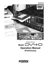
The model name, power requirement<br />
and serial number for the <strong>PD</strong>-<br />
<strong>606</strong> are indicated on the bottom<br />
side.<br />
MODEL <strong>PD</strong><strong>606</strong><br />
LOCATION RECORDER<br />
FOSTEX CO.<br />
INPUT: 12~24VDC<br />
SERIAL NO.<br />
MADE IN JAPAN<br />
12 Location Recorder Model <strong>PD</strong><strong>606</strong>
(dB/oct)<br />
HPF<br />
(Hz)<br />
ADJUST<br />
REW F FWD PLAY STOP<br />
-12 -6 OFF<br />
300<br />
200<br />
50<br />
130<br />
-12 -6 OFF<br />
300<br />
50<br />
Introduction<br />
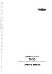
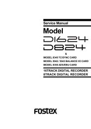
Cautions for use<br />
If you make recording or playback using a DVD-RAM disk, do not hang<br />
the unit using the shoulder belt, which may damage the DVD drive.<br />
Put the unit on a horizontal surface within the adjustable range of the<br />
height adjustment arm.<br />
* You can put the unit vertically when you make recording to the internal hard disk.<br />
PANEL LOCK<br />
LOCK OFF<br />
LOCATE REC END<br />
LOCATE ABS 0<br />
48V DM T12<br />
200<br />
130<br />
INPUT<br />
SEL<br />
MIC<br />
LINE<br />
-12 -6 OFF<br />
300<br />
200<br />
MIC<br />
DC-IN<br />
12-24V<br />
50<br />
130<br />
LINE<br />
48V DM T12<br />
-12 -6 OFF<br />
300<br />
200<br />
MIC<br />
50<br />
130<br />
LINE<br />
-12 -6 OFF<br />
300<br />
200<br />
50<br />
130<br />
-12 -6 OFF<br />
300<br />
200<br />
50<br />
130<br />
DISC IN<br />
48V DM T12<br />
48V DM T12<br />
48V DM T12<br />
48V DM T12<br />
DC-OUT<br />
12-24V<br />
( 0.5A MAX)<br />
PC<br />
USB<br />
HOST<br />
KYBD<br />
MIC<br />
LINE<br />
MIC<br />
1 2<br />
3 4 5 6<br />
ANALOG LINE OUT<br />
2<br />
PC<br />
HOST<br />
KYBD<br />
LINE<br />
MIC<br />
ST BUS OUT<br />
LINE<br />
OPEN<br />
ADJUST<br />
1 3 4 5 6<br />
ANALOG LINE OUT<br />
DC-IN<br />
DC-OUT<br />
12-24V<br />
12-24V<br />
ST BUS OUT<br />
( 0.5A MAX)<br />
USB<br />
Precautions on installation<br />
• Do not install the unit in the following conditions<br />
* In an extremely hot or cold place<br />
* In a moist place<br />
* In a vibrated place<br />
* In a dusty place<br />
* In a strong magnetic field or near a device which generates a<br />
magnetic field<br />
* In the direct sunshine<br />
* In the direct shower or rain<br />
• Notes on moisture condensation<br />
When you bring the unit from a cold place to a warm place,<br />
moisture may condense on the drive, display, panels, etc. In such a<br />
case, leave the unit for a while until it warms up and evaporates any<br />
moisture.<br />
Location Recorder Model <strong>PD</strong><strong>606</strong><br />
13
Introduction<br />
14 Location Recorder Model <strong>PD</strong><strong>606</strong>
Chapter 1: Main features<br />
Chapter 1: Main features<br />
Location Recorder Model <strong>PD</strong><strong>606</strong><br />
15
PC<br />
HOST<br />
KYBD<br />
LINE<br />
48V<br />
130<br />
50<br />
300<br />
-12 -6 OFF<br />
LOCK<br />
DM<br />
MIC<br />
T12<br />
200<br />
OFF<br />
LINE<br />
48V<br />
130<br />
50<br />
DM<br />
MIC<br />
T12<br />
200<br />
300<br />
-12 -6 OFF<br />
LINE<br />
48V<br />
130<br />
50<br />
DM<br />
MIC<br />
T12<br />
200<br />
300<br />
-12 -6 OFF<br />
LINE<br />
48V<br />
130<br />
50<br />
DM<br />
MIC<br />
T12<br />
200<br />
300<br />
-12 -6 OFF<br />
LINE<br />
48V<br />
130<br />
50<br />
DM<br />
MIC<br />
T12<br />
200<br />
300<br />
-12 -6 OFF<br />
LINE<br />
48V<br />
130<br />
50<br />
LOCATE REC END<br />
LOCATE ABS 0<br />
DM<br />
MIC<br />
T12<br />
200<br />
300<br />
-12 -6 OFF<br />
INPUT<br />
SEL<br />
(Hz)<br />
HPF<br />
(dB/oct)<br />
Chapter 1: Main features<br />
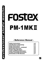
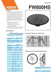
Main features and functions<br />
• Provides six analog inputs and outputs (on XLR connectors) and eight AES/<br />
EBU digital inputs and outputs (on a 25-pin D-sub connector). You can make<br />
up to six track recording to tracks 1 through 6, as well as six mono and stereo<br />
track recording (eight-track polyphonic file, in 44.1/48 kHz mode).<br />
Six analog inputs Six analog outputs<br />
6<br />
5<br />
PARALLEL<br />
9P-REMOTE<br />
DIGITAL I/ O<br />
( AUTO INPUT SELECT)<br />
4<br />
WORD<br />
OUT<br />
AUTO<br />
SEL<br />
WORD/<br />
VIDEO<br />
IN<br />
3<br />
ANALOG IN<br />
ON OFF<br />
2<br />
1<br />
TIME CODE<br />
IN<br />
OUT<br />
ADJUST<br />
1 2<br />
3 4 5 6<br />
ANALOG LINE OUT<br />
ADJUST<br />
DC-IN<br />
DC-OUT<br />
12-24V<br />
12-24V<br />
ST BUS OUT<br />
( 0.5A MAX)<br />
USB<br />
Eight digital inputs and outputs<br />
• Equipped with a 1.8-inch hard disk drive (80GB) and a 12-cm DVD multi<br />
drive as standard. You can directly make recording to the hard disk partition<br />
or DVD-RAM disk. In addition, you also can make "Auto copy", "File Copy"<br />
and "Disk Copy" between a DVD-RAM disk and a hard disk partition, as well<br />
as "Dual Drive Recording".<br />
The internal hard disk drive can be replaced with the optional hard disk<br />
drive unit (Model EX-HD1) by a user. The DVD combo drive is the slot loading<br />
type and can accept a 4.7GB, non-cartridge DVD-RAM, DVD-R or DVD-RW<br />
disk (only a DVD-RAM disk can be used for direct recording).<br />
1.8-inch hard disk drive<br />
12-cm DVD combo drive<br />
DISC IN<br />
PANEL LOCK<br />
REW F FWD PLAY STOP<br />
OPEN<br />
For the optional hard disk drive unit for replacement, ask your local <strong>Fostex</strong><br />
dealer or service station.<br />
16 Location Recorder Model <strong>PD</strong><strong>606</strong>
Chapter 1: Main features<br />
• The DVD-RAM disk format is conformed to "UDF Rev1.5", which ensures great<br />
compatibility with personal computers.<br />
• The recording file format is conformed to the versatile BWF format. You can<br />
export a recorded file including time code information to a BWF-compatible<br />
application.<br />
• Can be used with the optional AC adaptor or IDX ENDURA battery (V-mount<br />
type). You can stack up to four batteries for longer recording time.<br />
• Built in the internal generator with the jam sync function. The unit is equipped<br />
with the time code input/output connectors (XLR), so you can stripe not only<br />
the internal time code but also an external time code.<br />
6<br />
5<br />
PARALLEL<br />
9P-REMOTE<br />
4<br />
3<br />
ANALOG IN<br />
2<br />
1<br />
TIME CODE<br />
ADJUST<br />
WORD<br />
OUT<br />
IN<br />
OUT<br />
DIGITAL I/ O<br />
( AUTO INPUT SELECT)<br />
AUTO<br />
SEL<br />
WORD/<br />
VIDEO<br />
IN<br />
ON<br />
OFF<br />
TIME CODE IN/OUT connectors<br />
• Provides the word sync function, allowing synchronization with external<br />
digital equipment.<br />
6<br />
5<br />
PARALLEL<br />
9P-REMOTE<br />
4<br />
3<br />
ANALOG IN<br />
2<br />
1<br />
TIME CODE<br />
ADJUST<br />
WORD<br />
OUT<br />
IN<br />
OUT<br />
DIGITAL I/ O<br />
( AUTO INPUT SELECT)<br />
AUTO<br />
SEL<br />
WORD/<br />
VIDEO<br />
IN<br />
ON<br />
OFF<br />
WORD/VIDEO IN and WORD OUT connectors<br />
• Equipped with the [USB PC] port for PC connection. You can directly connect<br />
to a PC, allowing to mount the internal hard disk and DVD drives to the PC.<br />
The unit also provides the [USB HOST] port for future expansion.<br />
In addition, the [USB KYBD] port is also provided for USB keyboard<br />
connection, which allows you to enter file names and volume labels from a<br />
USB keyboard.<br />
1 2<br />
3 4 5 6<br />
ANALOG LINE OUT<br />
ADJUST<br />
DC-IN<br />
DC-OUT<br />
12-24V<br />
12-24V<br />
ST BUS OUT<br />
( 0.5A MAX)<br />
USB<br />
PC<br />
HOST<br />
KYBD<br />
USB port<br />
Location Recorder Model <strong>PD</strong><strong>606</strong><br />
17
Chapter 1: Main features<br />
• Provides the stereo bus output connector (XLR 5-pin). From this connector<br />
and output channels 1 through 6, you can output eight-channel signals.<br />
ADJUST<br />
DC-IN<br />
12-24V<br />
DC-OUT<br />
12-24V<br />
( 0.5A MAX)<br />
ST BUS OUT<br />
USB<br />
PC<br />
HOST<br />
KYBD<br />
Stereo bus output connector<br />
• You can export a recorded audio file to the AVID system by creating the ALE<br />
file.<br />
• The Mark/Cue function allows to store markers (cue points) during<br />
recording. You can locate or skip to a cue point quickly.<br />
• The "False start" function allows to cancel recording easily.<br />
• "Pre Record" function allows glitch-free recording. When this function is<br />
active, recent audio data is pooled in the buffer and recording starts from the<br />
audio data in the buffer.<br />
• During recording, the audio file is automatically saved every minute in<br />
background.<br />
• Equipped with the digital mixer which you can enjoy intuitive analog-like<br />
operation.<br />
Mixer section<br />
• In 24-bit/48kHz mode, you can record up to approximately 85 minutes onto<br />
six tracks, or 64 minutes onto eight tracks.<br />
* The times shown above are the recording times on a DVD-RAM disk (4.7GB)<br />
or a partition (approx. 4.5GB) of the hard disk.<br />
• In 24-bit mode, you can make recording with sampling frequencies of 44.1/<br />
48 kHz (up to 8 tracks), 88.2/96 kHz (up to 4 tracks) or 176.4/192 kHz (up to<br />
2 tracks).<br />
In 16-bit mode, you can make recording with sampling frequencies of 44.1/<br />
48 kHz (up to 8 tracks).<br />
18 Location Recorder Model <strong>PD</strong><strong>606</strong>
Chapter 1: Main features<br />
What is in the box?<br />
Make sure that the box contains the following. If any of them are missing, please<br />
contact your dealer.<br />
<strong>PD</strong><strong>606</strong><br />
Shoulder belt<br />
Operation manual (this manual)<br />
Driver software (CD) 1<br />
1<br />
1<br />
1<br />
<strong>PD</strong><strong>606</strong> options and related <strong>Fostex</strong> products<br />
The following <strong>PD</strong><strong>606</strong> options and related products are available.<br />
Ask your local <strong>Fostex</strong> dealer or sale office for details about them such as prices,<br />
specifications, etc.<br />
You can also get product information from our web site below.<br />
http://www.fostex.com<br />
Options<br />
• AC adaptor: Model AD15-4300 or AD-15C<br />
• 1.8-inch hard disk drive: Model EX-HD1<br />
• Battery plate: Model EX-BP1<br />
• Soft case: Model ZP-62<br />
Related products<br />
• Location recorder: Model <strong>PD</strong>204<br />
• DVD multitrack recorder: Model DV824<br />
• Portable location recorder: Model FR-2LE<br />
• Personal powered monitor: Model 6301B/BX/BE<br />
• Stereo headphones: Model T20RPMkII/T-5/T-7/T40RPMkII/T50RP<br />
Location Recorder Model <strong>PD</strong><strong>606</strong><br />
19
Chapter 1: Main features<br />
20 Location Recorder Model <strong>PD</strong><strong>606</strong>
Chapter 2: Preparation before using the <strong>PD</strong><strong>606</strong><br />
Chapter 2: Preparation before using the <strong>PD</strong><strong>606</strong><br />
This chapter explains what you should do before using the <strong>PD</strong><strong>606</strong> for the first time, including<br />
power connection, internal clock setting and preparation of the DVD-RAM disk.<br />
It also explains how to replace the internal hard disk drive.<br />
Chapter 2 - Table of contents<br />
Preparation of power supply .....................................................................................................22<br />
Mounting the battery .............................................................................................................23<br />
Important settings for using the battery .............................................................................24<br />
Battery priority setting (essential when using more than one battery) ......................24<br />
Low battery warning setting ..............................................................................................24<br />
Power supply priority setting (essential when using both [DC IN] and battery) ..25<br />
Protector adjustment ..........................................................................................................25<br />
Saving the battery power .......................................................................................................26<br />
Battery condition display ......................................................................................................26<br />
Dismounting the battery .......................................................................................................27<br />
Using [DC IN] (Connecting the AC adaptor) .......................................................................28<br />
Important settings for using [DC IN] ....................................................................................28<br />
Low battery warning setting ..............................................................................................28<br />
Power supply priority setting (essential when using both [DC IN] and battery) ..28<br />
Turning on the power ............................................................................................................29<br />
Display backlight and contrast .............................................................................................30<br />
Turning on the display backlight ......................................................................................30<br />
Adjusting the display contrast ..........................................................................................30<br />
Turning off the power ............................................................................................................30<br />
Internal clock setting ..................................................................................................................31<br />
Preparation of a DVD-RAM disk ................................................................................................33<br />
Inserting a disk ........................................................................................................................33<br />
Initial format of a DVD-RAM disk .........................................................................................34<br />
Replacing the internal hard disk drive .....................................................................................37<br />
Location Recorder Model <strong>PD</strong><strong>606</strong><br />
21
Chapter 2: Preparation before using the <strong>PD</strong><strong>606</strong><br />
Preparation of power supply<br />
The unit can operate on the mobile IDX ENDURA or NP-1 type battery, as well as the dedicated<br />
AC adaptor.<br />
IDX ENDURA battery<br />
NP-1 type battery<br />
Holder and holder plate for the NP series<br />
Dedicated AC adaptor (optional)<br />
: The IDX ENDURA battery, NP-1 type battery (including the holder and holder<br />
plate) and AC adaptor are not included with the unit. For the information about the<br />
AC adaptor, ask your dealer or the nearest FOSTEX service station.<br />
: In general, a battery is not charged when shipped. Therefore, before using<br />
the battery, you must charge it according to the manual of the battery (note that the<br />
<strong>PD</strong><strong>606</strong> does not provide the battery charge function). Also note that you must handle<br />
the battery correctly according to the manual of the battery.<br />
: You can mount the NP-1 battery housed in the dedicated holder to the<br />
<strong>PD</strong><strong>606</strong> without any special parts, however, the holder projects from the <strong>PD</strong><strong>606</strong> body.<br />
If you want to mount the NP-1 battery housed in the dedicated holder to the <strong>PD</strong><strong>606</strong><br />
without projecting from the <strong>PD</strong><strong>606</strong> body, the optional mounting hardware (Model<br />
EX-BP1) is needed. Ask your dealer or the local <strong>Fostex</strong> service station for installing<br />
the mounting hardware. The mounting hardware must be installed by <strong>Fostex</strong> service<br />
station.<br />
* IDX, IDX (logo), ENDURE, V-Mount, V-Plate, Digi-View and i-Trax are the trademarks of IDX Company Ltd..<br />
22 Location Recorder Model <strong>PD</strong><strong>606</strong>
Chapter 2: Preparation before using the <strong>PD</strong><strong>606</strong><br />
Mounting the battery<br />
The ENDURA battery is mounted to the bottom of the <strong>PD</strong><strong>606</strong>.<br />
There are two mounts for mounting the batteries. If you use the non-PowerLink type<br />
batteries, you can mount one battery for each base. If you use the PowerLink type<br />
batteries, you can mount up to four batteries (two batteries for each base).<br />
: When you mount or replace the battery, make sure that the unit power is off.<br />
By sudden power failure, memory data may be reset or the unit may be damaged because<br />
the unit handles data while the power is on. However, note that, if you set two<br />
batteries, you can replace a battery which is not currently active.<br />
: If you use the IDX ENDURA battery, read the operation manual supplied with<br />
the battery and handle it correctly. The <strong>PD</strong><strong>606</strong> does not provide battery charge function.<br />
Charge the IDX ENDURA battery correctly according to the battery manual.<br />
Battery mount 2 (BATT2)<br />
Battery mount 1 (BATT1)<br />
ENDURA battery<br />
Connectors<br />
ENDURA battery<br />
<br />
Location Recorder Model <strong>PD</strong><strong>606</strong><br />
23
Chapter 2: Preparation before using the <strong>PD</strong><strong>606</strong><br />
When you use PowerLink batteries, you<br />
can mount up to four batteries (two batteries<br />
for each base, as shown on the<br />
right).<br />
: When you mount four batteries,<br />
you cannot use the protector on the<br />
bottom panel. Use the unit horizontally.<br />
<br />
• When you use PowerLink batteries, use batteries of the same charging<br />
condition. If the charging conditions are significantly different, the PowerLink<br />
function may not operate correctly resulting the <strong>PD</strong><strong>606</strong> powered off.<br />
• You cannot mount more than two batteries. Each battery mount can accept up<br />
to two batteries.<br />
Important settings for using the battery<br />
Battery priority setting (essential when using more than one battery)<br />
When you use two batteries or four PowerLink batteries, you must set the battery<br />
priority (BATT1 or BATT2).<br />
You can specify the battery to be used preferentially. When the preferential battery<br />
gets empty, the display shows the warning popup window and the other battery automatically<br />
takes over.<br />
You can make setting via the quick setup mode or via the "Active battery" item in the<br />
"BATTERY SETUP" menu of the MENU mode (see pages 77 and 175).<br />
Low battery warning setting<br />
Whether you use a battery with or without BMS (Battery Management System), you<br />
can set the threshold voltage for warning low battery.<br />
When the battery voltage gets lower than the threshold voltage you set, the warning<br />
tone is output from the headphones connected to the unit.<br />
By default, the threshold voltage is set to 13.2V for battery with BMS or 13.0V for<br />
battery without BMS. However, you can set the desired threshold voltage via the "BATT.<br />
warning" item in the "BATTERY SETUP" menu of the MENU mode (see page 172).<br />
: When you use a battery with BMS (Battery Management System), you can check<br />
the battery information via the "BATT. status" item in the "BATTERY SETUP" menu of<br />
the MENU mode (see page 179).<br />
: When you use a battery with BMS (Battery Management System), you can check<br />
the remaining time until the battery voltage reaches the threshold voltage in one-minute<br />
steps via the "BATT. Remain" item in the "BATTERY SETUP" menu of the MENU mode<br />
(see page 178).<br />
: While the battery has power, the output voltage is between 13 V to 15 V. When<br />
the remaining power gets short, the output voltage rapidly drops. Therefore, to replace<br />
the battery well in advance, we recommend setting the threshold voltage to 13 V or<br />
around.<br />
24 Location Recorder Model <strong>PD</strong><strong>606</strong>
Chapter 2: Preparation before using the <strong>PD</strong><strong>606</strong><br />
Power supply priority setting (essential when using both [DC IN] and a battery)<br />
When you use both a battery and the [DC IN] connector, you must set the power<br />
supply priority ("DC-IN" or "BATT"). For example, if you set it to "DC-IN", the battery<br />
automatically takes over only when the power supply from the "DC-IN" jack is cut off<br />
(power failure, disconnection, etc).<br />
Note that, if you use only batteries, you do not need to make this setting.<br />
You can make setting via the "Power priority" item in the "BATTERY SETUP" menu of<br />
the MENU mode (see page 174).<br />
Protector adjustment<br />
When the battery is mounted, pull out the protector to protect the battery, as shown<br />
below. While sliding the [ADJUST] levers on left and right side panels to the arrow<br />
direction, pull out the protector. There are two locked positions for the protector.<br />
Set it to the appropriate position. Note that you should push it down when replacing<br />
the battery.<br />
Protector<br />
E<br />
OUT<br />
ADJUST<br />
[ADJUST] levers<br />
: The protector can protect the IDX ENDURA-7 and ENDURA-7S. When you<br />
use the ENDURA-10 or ENDURA-10S, or PowerLink is active, we recommend using<br />
the <strong>PD</strong><strong>606</strong> horizontally.<br />
Location Recorder Model <strong>PD</strong><strong>606</strong><br />
25
Chapter 2: Preparation before using the <strong>PD</strong><strong>606</strong><br />
Saving the battery power<br />
The <strong>PD</strong><strong>606</strong> offers the following measures for saving the battery power to extend the<br />
battery life.<br />
• Pressing the [STOP] key stops the disk rotation to save the power consumption.<br />
It is also possible to set the desired pause release time using the "Pause time" item in<br />
the SYS SETUP menu of the MENU mode (the default pause time is three minutes).<br />
• When the internal monitor speaker is not used or when a headphone plug is inserted<br />
to the [PHONES] jack, no power is supplied to the amplifier for the speaker.<br />
The following describes some tips for saving the battery power, as well as some notes on<br />
using the battery.<br />
• When you do not operate the unit on battery power for a long period of time, remove<br />
the battery. Even if the [POWER] switch is set to "OFF", a small amount of electric<br />
power is consumed.<br />
• Set the monitor level as lower as possible (regardless of whether using headphones<br />
or the internal monitor speaker).<br />
• You should use the display backlight only when needed.<br />
• When you do not use a DVD-RAM disk, remove the disk.<br />
• The load impedance connected to <strong>PD</strong><strong>606</strong> output connectors should be greater than<br />
10k ohm.<br />
• When converting a balanced output to an unbalanced output, you should not<br />
connect the unused pin to the ground pin and leave it open. Though it lowers the<br />
output level by 6dB, it does not influence to the audio characteristics.<br />
You can check the current battery remaining amount in realtime by following the procedure<br />
described below.<br />
Battery condition display<br />
You can check the battery remaining amount in realtime from the [ST BUS] bar-graph<br />
meters beside the LCD display on the front panel.<br />
By pressing and holding down the [EXIT/BATT] key when you use a BMS battery and<br />
the display shows the Home screen (in stop, playback or record mode), the [ST BUS]<br />
bargraph meters show the battery remaining amount in % and the display pops up the<br />
battery power voltage in V. Releasing the [EXIT/BATT] key returns the meters to the<br />
stereo buss level monitoring and dismiss the popup window).<br />
When you use a non-BMS battery, only the display pops up the battery power voltage.<br />
EXIT<br />
[ST BUS] bar-graph meters<br />
[EXIT / BATT] key<br />
BATT<br />
POWER<br />
QUICK SET TIME FILE SEL LIGHT<br />
EXIT<br />
LINK MASTER<br />
ENTER / YES<br />
space<br />
ABC<br />
DEF<br />
LOCATE<br />
FILE<br />
CUE<br />
CIRCLE TAKE<br />
PAUSE<br />
REC<br />
ON<br />
OFF<br />
SHIFT TC SET DRV/PAT. CONTRAST BATT MENU<br />
MS R<br />
1 1 / 3 / 5 + 2 / 4 / 6<br />
ACCESS<br />
C4 L<br />
2 L+R<br />
C3 6<br />
3 READY TRK<br />
HDD DVD<br />
C2 5<br />
4 C1<br />
ST<br />
<strong>PD</strong><strong>606</strong> LOCATION RECORDER<br />
SOLO<br />
MONO<br />
MONITOR<br />
1<br />
4<br />
7<br />
GHI<br />
PQRS<br />
2<br />
JKL<br />
3<br />
MNO<br />
CLEAR<br />
5<br />
6<br />
TUV WXYZ symbol<br />
Shows the<br />
8<br />
9<br />
0<br />
BATT1<br />
remaining<br />
amount<br />
PREV CUE NEXT<br />
PRE REC JAM<br />
ON<br />
OFF<br />
SLATE FALSE START<br />
TONE<br />
OFF<br />
MIC<br />
Shows the<br />
BATT2<br />
remaining<br />
amount<br />
MIN<br />
MAX<br />
PHONES<br />
26 Location Recorder Model <strong>PD</strong><strong>606</strong>
Chapter 2: Preparation before using the <strong>PD</strong><strong>606</strong><br />
Dismounting the battery<br />
To dismount the battery, make sure that the power is off, and remove the battery<br />
while pressing the release button on the IDX ENDURA battery or press down the eject<br />
lever on the <strong>PD</strong><strong>606</strong>.<br />
Eject lever on the <strong>PD</strong><strong>606</strong><br />
Eject lever on the <strong>PD</strong><strong>606</strong><br />
Release button<br />
: Dispose the used battery properly (see the instruction manual of your battery).<br />
Keep the removed battery away from children.<br />
Location Recorder Model <strong>PD</strong><strong>606</strong><br />
27
Chapter 2: Preparation before using the <strong>PD</strong><strong>606</strong><br />
Using [DC-IN] (Connecting the AC adaptor)<br />
You can connect the AC adaptor or another appropriate power source to the [DC IN]<br />
connector on the left side panel of the <strong>PD</strong><strong>606</strong>. If you use the AC adaptor, insert the<br />
XLR-4-32 type connector of the AC adaptor to the [DC IN] connector until it is locked,<br />
then connect the AC plug to the AC main outlet (see the figure below).<br />
<br />
• When you connect or disconnect the connector, make sure that the power is off.<br />
• Use only the <strong>Fostex</strong> dedicated AC adaptor. Using another AC adaptor may damage<br />
the <strong>PD</strong><strong>606</strong> due to the mismatch of the power voltage, polarity, etc. When connect or<br />
disconnect the AC adaptor, make sure that the [POWER] switch is set to "OFF".<br />
The AC adaptor for the <strong>PD</strong><strong>606</strong> is optionally available (ask your local <strong>Fostex</strong> dealer or<br />
sale office for purchasing the option).<br />
1 2<br />
3 4 5 6<br />
ANALOG LINE OUT<br />
ADJUST<br />
DC-IN<br />
DC-OUT<br />
12-24V<br />
12-24V<br />
ST BUS OUT<br />
( 0.5A MAX)<br />
USB<br />
PC<br />
HOST<br />
KYBD<br />
[DC IN] connector<br />
AC adaptor<br />
To the AC main outlet<br />
Important settings for using [DC IN]<br />
Low battery warning setting<br />
When you get the power from the [DC IN] connector (such as use the AC adaptor), you<br />
can set the threshold voltage for warning low battery.<br />
When the DC-IN voltage gets lower than the threshold voltage you set, the warning<br />
tone is output from the headphones connected to the unit.<br />
By default, the threshold voltage is set to 13.0V. However, you can set the desired<br />
threshold voltage via the "DC-IN warning" item in the "BATTERY SETUP" menu of the<br />
MENU mode (see page 173).<br />
Power supply priority setting (essential when using both [DC IN] and battery)<br />
When you use both a battery and the [DC IN] connector, you must set the power<br />
supply priority ("DC-IN" or "BATT"). For example, if you set it to "DC-IN", a warning<br />
message pops up on the display and the battery automatically takes over only when<br />
the power supply from the "DC-IN" jack is cut off (power failure, disconnection, etc).<br />
Note that, if you use only batteries, you do not need to make this setting.<br />
You can make setting via the "Power priority" item in the "BATTERY SETUP" menu of<br />
the MENU mode (see page 174).<br />
28 Location Recorder Model <strong>PD</strong><strong>606</strong>
Chapter 2: Preparation before using the <strong>PD</strong><strong>606</strong><br />
Turning on the power<br />
After mounting the battery or connecting the power source such as the AC adaptor to<br />
the [DC IN] connector, you can turn on the power by setting the [POWER] switch to<br />
"ON". The unit starts up and the screen similar to below appears (the screen example<br />
below shows the one the first time you turn on the power after purchasing the unit).<br />
[POWER] switch<br />
POWER<br />
QUICK SET TIME FILE SEL LIGHT<br />
EXIT<br />
LINK MASTER<br />
ENTER / YES<br />
space<br />
ABC<br />
DEF<br />
LOCATE<br />
FILE<br />
CUE<br />
CIRCLE TAKE<br />
PAUSE<br />
REC<br />
ON<br />
1<br />
GHI<br />
2<br />
JKL<br />
3<br />
MNO<br />
CLEAR<br />
PREV CUE NEXT<br />
OFF<br />
SHIFT TC SET DRV,PAT. CONTRAST BATT MENU<br />
4<br />
5<br />
6<br />
PRE REC<br />
JAM<br />
SLATE<br />
FALSE START<br />
MS R<br />
C4 L<br />
C3 6<br />
C2 5<br />
1 1 / 3 / 5 + 2 / 4 / 6<br />
2 ST BUS<br />
3 READY TRK<br />
4 C1<br />
ACCESS<br />
HDD DVD<br />
PQRS TUV WXYZ symbol<br />
7<br />
8<br />
9<br />
0<br />
ON<br />
OFF<br />
TONE<br />
OFF<br />
MIC<br />
ST<br />
SOLO<br />
MONO<br />
<strong>PD</strong><strong>606</strong> LOCATION RECORDER<br />
MONITOR<br />
MIN<br />
MAX<br />
PHONES<br />
This screen shows the current drive is partition 01 of the internal hard disk and there<br />
is no file recorded in the partition.<br />
The internal hard disk has been formatted when shipped. So you can make recording<br />
to the partition in this condition. The hard disk is divided into 16 partitions (approximately<br />
4.5GB per partition). If you want to record a file to another partition, select the<br />
desired partition by using the drive selection function (see page 86).<br />
: If you make recording to a DVD-RAM disk, you must format the disk (see page<br />
34) and select the DVD-RAM drive by using the drive selection function.<br />
: When the power is being supplied from a battery, the [BATT1] or [BATT2]<br />
indicator on the top panel lights, while the "POWER" area on the display shows "BATT1"<br />
or "BATT2".<br />
These depend on the settings of the "Active battery" and "Power priority" items in the<br />
"BATTERY SETUP" menu of the MENU mode.<br />
Battery indicators<br />
When the power is being supplied from the [DC IN] connector, both battery indicators<br />
on the top panel are unlit, while the "POWER" area on the display shows "DC-IN".<br />
Location Recorder Model <strong>PD</strong><strong>606</strong><br />
29
Chapter 2: Preparation before using the <strong>PD</strong><strong>606</strong><br />
Display backlight and contrast<br />
[LIGHT / CONTRAST] key<br />
[SHIFT] key<br />
[MENU] dial<br />
LINK MASTER<br />
POWER<br />
QUICK SET TIME FILE SEL LIGHT<br />
EXIT<br />
ENTER / YES<br />
ON<br />
OFF<br />
MS R<br />
C4 L<br />
SHIFT TC SET DRV,PAT. CONTRAST BATT MENU<br />
1 1 / 3 / 5 + 2 / 4 / 6<br />
ACCESS<br />
2 ST BUS<br />
1<br />
4<br />
C3 6<br />
C2 5<br />
3 READY TRK<br />
4 C1<br />
HDD<br />
DVD<br />
7<br />
SOLO<br />
ST<br />
MONO<br />
<strong>PD</strong><strong>606</strong> LOCATION RECORDER<br />
MONITOR<br />
Turning on the display backlight<br />
Turns on or off the backlight of the display.<br />
Pressing the [LIGHT/CONTRAST] key turns on the backlight of the display, which is<br />
automatically turned off after three seconds. If you keep holding down the [LIGHT/<br />
CONTRAST] key for more than three seconds, the display shows "--Light on hold--" and<br />
the backlight keeps on lighting until you press this key again.<br />
: When you operate the unit on battery, we recommend not using the display<br />
backlight unless necessary, because the backlight consumes the battery power.<br />
Adjusting the display contrast<br />
The display contrast is adjusted appropriately when shipped. However, you can adjust<br />
it as your favor by the following procedure after turning on the power.<br />
1) Press the [SHIFT] key to enter shift mode, followed by the [LIGHT/CONTRAST] key.<br />
The display shows the popup screen for adjusting the display contrast.<br />
2) Use the [MENU] dial to adjust the display contrast.<br />
Rotating the [MENU] dial clockwise weakens the contrast while rotating the dial counter<br />
clockwise strengthens the contrast.<br />
3) Press the [ENTER/YES] key to confirm the setting.<br />
The display contrast is set.<br />
The popup screen is dismissed and the unit exits the contrast adjustment mode.<br />
Turning off the power<br />
Before you turn off the power, make sure that the unit stops access to the drive.<br />
To turn off the power, switch the [POWER] switch to the OFF position.<br />
The display backlight flashes weakly and slowly. This indicates that the internal TC generator<br />
is still working after turning off the main unit.<br />
The time until the TC generator turns off is set to five minutes by default, however, you can<br />
set it to the desired time via the "TC PWR Timer" item in the "TC SETUP" menu of the MENU<br />
mode (see page 195).<br />
30 Location Recorder Model <strong>PD</strong><strong>606</strong>
Chapter 2: Preparation before using the <strong>PD</strong><strong>606</strong><br />
Internal clock setting<br />
The <strong>PD</strong><strong>606</strong> offers realtime clock.<br />
The realtime clock data is used for a default file name when creating a new audio file on a disk,<br />
the file creation date/time information, the time code start time when recording a time code by<br />
the internal time code generator, and so on (see Notes below) .<br />
The realtime clock is adjusted according to the local time when shipped, therefore, set the time<br />
to your local time before using the <strong>PD</strong><strong>606</strong> by following the procedure below.<br />
: The realtime clock date is used for the default file name of a newly created file<br />
when the file name mode is set to "DATE" using the "Default file name" item in the "SYS<br />
SETUP" menu of the MENU mode (see page 140).<br />
The following screen example shows the Home screen of the file created when the file<br />
name mode is set to "DATE".<br />
File name<br />
: Only when the TC GEN mode is set to "24H RUN", the realtime clock data is used<br />
as the TC start time (see pages 76 and 183 for details about the TC GEN mode).<br />
The following procedure assumes that partition 1 (PT01) which has no recorded file is currently<br />
selected.<br />
1) While the unit is stopped, press the [SHIFT] key to enter shift mode, followed by the<br />
[ENTER/YES] key.<br />
The unit enters MENU mode and brings up the MENU list screen for selecting the desired<br />
main menu.<br />
2) While "SYS SETUP" is highlighted, press the [ENTER/YES] key.<br />
The display shows the SYS SETUP menu screen, on which you can select system setup<br />
menu item.<br />
Location Recorder Model <strong>PD</strong><strong>606</strong><br />
31
Chapter 2: Preparation before using the <strong>PD</strong><strong>606</strong><br />
3) Use the [MENU] dial to select "Adjust RTC" and press the [ENTER/YES] key.<br />
The display now shows current internal clock time which runs in realtime.<br />
By pressing the [ENTER/YES] key while "SET "00s":" is highlighted (as the screen shown<br />
above right), the second field is reset to "00". If you reset the second field when the<br />
second value is 30 or more, the minute field value is incremented. If you reset the second<br />
field when the second value is less than 30, only the second field is reset.<br />
4) Use the [MENU] dial to select "EDIT" and press the [ENTER/YES] key.<br />
The clock data at the moment when you press the [ENTER/YES] key is held and you can<br />
now edit it (the second field flashes).<br />
Flashing<br />
5) Enter the desired date/time data.<br />
Use the [MENU] dial (or the alphanumeric keys) to enter a desired value to the current<br />
cursor position (flashing field).<br />
You can move the cursor position using the [ ] and [ ] keys.<br />
6) After entering date/time data, move the cursor to the offset time value (by default, "+0:00")<br />
of Time Zone, and enter the desired offset time according to the country where the unit is<br />
used.<br />
By rotating the [MENU] dial, you can select the desired offset time within the range<br />
between -12:00 and +13:00.<br />
Example: London: +0:00, Tokyo: +9:00, Los Angels: -8:00 (-7:00)<br />
Flashing<br />
7) After entering all data, press the [ENTER/YES] key to start running the clock.<br />
: We recommend entering a time shortly ahead of "now" (such as one<br />
minute ahead) in step 5 above and pressing the [ENTER/YES] key (in step 7<br />
above) at the moment when the current time reaches the entered time.<br />
8) Press the [EXIT] key repeatedly to exit the MENU mode.<br />
32 Location Recorder Model <strong>PD</strong><strong>606</strong>
Chapter 2: Preparation before using the <strong>PD</strong><strong>606</strong><br />
Preparation of a DVD-RAM disk<br />
The internal DVD multi drive of the <strong>PD</strong><strong>606</strong> features a slim drive and accepts a non-cartridge DVD-<br />
RAM disk (4.7GB, 2-3 x or more than 3x). An unused DVD-RAM disk must be formatted in UDF 1.5.<br />
Inserting a disk<br />
The following procedure assumes that partition 1 (PT01) which has no recorded file is<br />
currently selected.<br />
1) Slide the [OPEN] lever to the right.<br />
The cover of the disk tray opens a little, so you can open the cover by hand.<br />
DISC IN<br />
PANEL LOCK<br />
REW<br />
F FWD<br />
LOCK<br />
OFF<br />
OPEN<br />
OPEN<br />
LINK MASTER<br />
space<br />
ABC<br />
DEF<br />
LOCATE<br />
FILE<br />
CUE<br />
POWER<br />
QUICK SET TIME FILE SEL LIGHT<br />
EXIT<br />
ENTER / YES<br />
ON<br />
1<br />
GHI<br />
2<br />
JKL<br />
3<br />
MNO<br />
CLEAR<br />
PREV CUE NEXT<br />
OFF<br />
SHIFT TC SET DRV,PAT. CONTRAST BATT MENU<br />
4<br />
5<br />
6<br />
PRE REC<br />
JAM<br />
SLATE<br />
MS R<br />
C4 L<br />
1 1 / 3 / 5 + 2 / 4 / 6<br />
2 ST BUS<br />
ACCESS<br />
PQRS<br />
TUV<br />
WXYZ<br />
symbol<br />
ON<br />
OFF<br />
C3 6<br />
3 READY TRK<br />
HDD<br />
DVD<br />
7<br />
8<br />
9<br />
0<br />
2) Insert a disk to the drive slot.<br />
The unit loads the disk and reads the disk information.<br />
When the unit is shipped from the factory, the current drive is set to the internal hard<br />
disk drive, so the display shows the Home screen for partition 1. Therefore, the screen<br />
does not change when loading a DVD-RAM disk.<br />
To eject the disk, press the eject button located at the left of the slot.<br />
: Do not eject a DVD disk from the disk tray while the current drive is set<br />
to the DVD drive and the disk is running. Before you eject the disk, make sure<br />
that the disk stopped (the [PAUSE] indicator is unlit). Also note that it takes some<br />
time to eject the disk. Do not press the [PLAY], [F FWD] or [REW] key.<br />
Eject button<br />
POWER<br />
QUICK SET TIME FILE SEL LIGHT<br />
EXIT<br />
ENTER<br />
YES<br />
space<br />
ABC<br />
DEF<br />
LOCATE<br />
FILE<br />
CU<br />
ON<br />
1<br />
GHI<br />
2<br />
JKL<br />
3<br />
MNO<br />
CLEAR<br />
PREV CUE NEXT<br />
OFF<br />
SHIFT TC SET DRV/PAT. CONTRAST BATT/ MENU<br />
4<br />
5<br />
6<br />
PRE REC<br />
JAM<br />
SLA<br />
MS R<br />
C4 L<br />
1 1 / 3 / 5 + 2 / 4 / 6<br />
2 ST BUS<br />
ACCESS<br />
PQRS<br />
TUV<br />
WXYZ<br />
symbol<br />
ON<br />
OFF<br />
C3 6<br />
C2 5<br />
3 READY TRK<br />
4 C1<br />
HDD<br />
DVD<br />
7<br />
8<br />
9<br />
0<br />
3) Close the tray cover until locked by hand.<br />
Now you can format the DVD-RAM disk by following the procedure described on the next<br />
page.<br />
Location Recorder Model <strong>PD</strong><strong>606</strong><br />
33
Chapter 2: Preparation before using the <strong>PD</strong><strong>606</strong><br />
Initial format of a DVD-RAM disk<br />
1) While the unit is stopped, press the [SHIFT] key to enter shift mode, followed by the<br />
[ENTER/YES] key.<br />
The unit enters MENU mode and brings up the MENU list screen for selecting the desired<br />
main menu.<br />
2) Use the [MENU] dial to select "DISK UTILITY" and press the [ENTER/YES] key.<br />
The display shows the DISK UTILITY menu screen, on which you can select disk utility<br />
menu item.<br />
3) Use the [MENU] dial to select "Format" and press the [ENTER/YES] key.<br />
The display now shows the screen for formatting.<br />
On this screen, you can make the following four settings.<br />
This procedure example assumes that the "Reel No" and "Physical Format" items are left<br />
as default.<br />
Drive<br />
Selects the drive to be formatted.<br />
You can select "DVD-RAM" or any of the hard disk partitions ("PT01HD" through<br />
"PT16HD").<br />
Sets the reel number for the DVD-RAM disk or partition to be formatted.<br />
The default reel numbers for a DVD-RAM disk and partitions are as follows.<br />
Reel No<br />
DVD-RAM: S001<br />
Partitions: S002 through S017<br />
You can change the reel number later via the "Reel No" item in the "DISK UTILITY"<br />
menu of the MENU mode (see page 208).<br />
Format<br />
Mode<br />
Physical<br />
Format<br />
Selects the format mode.<br />
When you format a DVD-RAM disk, only "Normal" is available.<br />
When you format a partition, "Normal" and "DDR" are available. The "DDR" option is<br />
used when executing dual drive recording described later (see page115).<br />
Selects whether or not you physically format a DVD-RAM disk or partition.<br />
When selecting "Off", a quick format is performed.<br />
When selecting "On", a physical format is performed, which takes longer time (see<br />
on the next page).<br />
34 Location Recorder Model <strong>PD</strong><strong>606</strong>
Chapter 2: Preparation before using the <strong>PD</strong><strong>606</strong><br />
: When formatting a well-used DVD-RAM disk, perform the physical format.<br />
The following shows the approximate required time for formatting a 4.7GB<br />
DVD-RAM disk.<br />
When "Physical Format" is set to "Off":<br />
When "Physical Format" is set to "On":<br />
approx. 1 min. 30 sec.<br />
approx. 1 hour 30 min.<br />
4) Press the [ENTER/YES] key.<br />
You can now select the drive.<br />
Flashing<br />
5) Use the [MENU] dial to select "DVD-RAM" and press the [ENTER/YES] key.<br />
The drive selection is confirmed and "Reel No: [S001" is highlighted.<br />
Flashing<br />
For the operation of setting the desired reel number on this screen, see the next page.<br />
Also, you can set the desired reel number after formatting via the "Reel No" item in the<br />
"DISK UTILITY" menu of the MENU mode (see page 208).<br />
6) Use the [MENU] dial to highlight "[EXECUTE]" and press the [ENTER/YES] key.<br />
The display shows the caution screen, where "Are you sure?" flashes.<br />
Flashing<br />
7) While "Are you sure?" flashes, press the [ENTER/YES] key.<br />
The unit starts formatting.<br />
The display shows the formatting countdown, as well as the progress status by the<br />
bar-graph meter. When formatting completes, the display shows "Fmt. Completed!".<br />
: Note that the formatting countdown and bar-graph meter show the approximate<br />
information. Do not proceed to the next step until "Fmt. Completed!"<br />
is shown.<br />
Location Recorder Model <strong>PD</strong><strong>606</strong><br />
35
Chapter 2: Preparation before using the <strong>PD</strong><strong>606</strong><br />
: In rare cases, the unit shows "Disk error!" and releases the disk lock after<br />
formatting is performed. In such a case, set "Physical Format" to "On" and format<br />
the disk again. If "Disk error!" is shown again after the physical format is performed,<br />
do not use the disk.<br />
8) After formatting, press the [EXIT] key to exit the MENU mode.<br />
The display returns to the Home screen previously shown before entering the MENU<br />
mode.<br />
To make recording to the DVD-RAM disk, select the current drive to the DVD drive (see<br />
page 86 for details).<br />
: If you format a DVD-RAM disk when any partition is selected as the current<br />
drive, the current drive does not change after formatting is completed. Therefore,<br />
if you want to make recording to the DVD-RAM disk, you must change the<br />
current drive from the partition to the DVD drive.<br />
On the other hand, if you format a partition when the DVD drive is selected as the<br />
current drive, the current drive automatically changes to the partition after formatting<br />
is completed.<br />
How to set the desired reel number<br />
During the process of initial formatting, you can set the desired reel number by the<br />
following procedure.<br />
1) While "Reel No: [S001" is highlighted, press the [ENTER/YES] key.<br />
The first digit of the reel number field starts flashing. You are ready for editing the<br />
reel number.<br />
flashing<br />
2) Use the [MENU] dial (or the alphanumeric keys) to enter the desired reel number.<br />
Use the [ ] and [ ] keys to move the cursor position when entering the number<br />
using the [MENU] dial.<br />
When using the alphanumeric keys for entering characters, pressing any other<br />
alphanumeric key moves the cursor to the right automatically.<br />
Pressing the [CLEAR] key clears the character at the cursor position.<br />
3) After editing the reel number, press the [ENTER/YES] key to confirm your setting.<br />
36 Location Recorder Model <strong>PD</strong><strong>606</strong>
Chapter 2: Preparation before using the <strong>PD</strong><strong>606</strong><br />
Replacing the internal hard disk drive<br />
You can replace the internal hard disk drive with the optional Model EX-HD1 hard disk drive by<br />
following the procedure below.<br />
: Before you replace the hard disk drive, turn off the power and remove the AC<br />
adaptor (or battery). Handle the optional and internal hard disk drives gently and carefully<br />
because they contain precision parts.<br />
: When you use the unit vertically with the front panel down, put the unit on a soft<br />
fabric, etc. and fix the unit so that it does not fall down.<br />
Optional hard disk drive (Model EX-HD1)<br />
: The optional hard disk is formatted when<br />
shipped so you do not have to format it after mounting<br />
it to the <strong>PD</strong><strong>606</strong>.<br />
1) Loosen the four fixed screws around battery mount 1 and remove the panel.<br />
The internal hard disk drive appears as indicated in the figure below.<br />
Fixed screw 1<br />
Fixed screw 2<br />
Fixed screw 3 Fixed screw 4<br />
Internal hard disk drive<br />
2) Loosen the two fixed screws which fixes the hard disk drive and remove the hard disk drive.<br />
The fixed screws are not removed. Grip the screw heads by fingers and pull out the hard<br />
disk drive. The drive is connected to the connector inside so take great care for pulling it<br />
out.<br />
Location Recorder Model <strong>PD</strong><strong>606</strong><br />
37
Chapter 2: Preparation before using the <strong>PD</strong><strong>606</strong><br />
Fixed screw 1 Fixed screw 2<br />
After removing the hard disk drive, you can see the connector inside for connecting with<br />
the hard disk drive.<br />
Connector<br />
3) Insert the optional hard disk drive to the slot.<br />
Insert the drive into the slot until it is fully inserted to the connector inside, and fix it with<br />
two screws.<br />
4) Cover the slot with the panel and fix it with four screws.<br />
Now you finish hard disk drive replacement.<br />
38 Location Recorder Model <strong>PD</strong><strong>606</strong>
Chapter 3: Names and Functions<br />
Chapter 3: Names and Functions<br />
Chapter 3 - Table of contents<br />
Left side panel .............................................................................................................................40<br />
Right side panel ...........................................................................................................................42<br />
Front panel ..................................................................................................................................45<br />
Top panel .....................................................................................................................................53<br />
Rear panel ...................................................................................................................................55<br />
LCD display details .....................................................................................................................56<br />
Location Recorder Model <strong>PD</strong><strong>606</strong><br />
39
PC<br />
Chapter 3: Names and Functions<br />
Left side panel (inputs/outputs)<br />
1<br />
1 2<br />
3 4 5 6<br />
ANALOG LINE OUT<br />
11 ADJUST<br />
2<br />
DC-IN<br />
DC-OUT<br />
12-24V<br />
12-24V<br />
ST BUS OUT<br />
( 0.5A MAX)<br />
USB<br />
PC<br />
HOST<br />
KYBD<br />
10 9 8 7 6<br />
5<br />
4<br />
3<br />
1. [ANALOG LINE OUT] connectors (XLR-3-32 type/balanced)<br />
These connectors feed analog audio signals of tracks 1 through 6.<br />
1<br />
2<br />
1<br />
2<br />
3<br />
GND<br />
HOT<br />
COLD<br />
2. Handle<br />
Used to fix the supplied shoulder belt.<br />
3<br />
3. Angle adjustment arm<br />
Used to adjust the angle of the unit when you use it on a desk.<br />
4 5 6<br />
ANALOG LINE OUT<br />
ST BUS OUT<br />
ADJUST<br />
1 2<br />
3 4 5 6<br />
ANALOG LINE OUT<br />
DC-IN<br />
DC-OUT<br />
12-24V<br />
12-24V<br />
ST BUS OUT<br />
( 0.5A MAX)<br />
USB<br />
HOST<br />
KYBD<br />
4. Internal monitor speaker<br />
Outputs audio signals of tracks 1 though 6, error tones, etc.<br />
When a headphones plug is inserted to the [PHONES] jack, the monitor speaker is<br />
inactive.<br />
40 Location Recorder Model <strong>PD</strong><strong>606</strong>
Chapter 3: Names and Functions<br />
5. [ST BUS OUT] connector (XLR-5-32 type/balanced)<br />
Outputs the stereo bus L/R signals. It is used to connect to an external audio<br />
device. The reference level is set to +4dBu by default but you can change it to<br />
-10dBu or -60dBu using the "Stereo out level" menu item in the "SYS SETUP" menu<br />
of the MENU mode (see page 161).<br />
1<br />
2<br />
3<br />
4<br />
1 GND<br />
2 L HOT<br />
3 L COLD<br />
4 R HOT<br />
5 R COLD<br />
6. [USB HOST] connector (Series A Receptacle/USB 2.0 High speed)<br />
Not currently supported. Prepared for the future expansion.<br />
5<br />
1 2 3 4<br />
1 VBUS<br />
2 D -<br />
3 D +<br />
4 GND<br />
: When you connect the <strong>PD</strong><strong>606</strong> to a personal computer using the<br />
[USB PC] connector, do not connect any device to the [USB HOST] connector.<br />
7. [USB KYBD] connector (Series A Receptacle/USB 1.1)<br />
Used to connect to a USB keyboard. You can control the <strong>PD</strong><strong>606</strong> from the keyboard<br />
(see “Connection examples of a keyboard” on page 66).<br />
1 2 3 4<br />
4 GND<br />
8. [USB PC] connector (Series B Receptacle)<br />
Used to connect to a personal computer. You can transfer audio files between the<br />
<strong>PD</strong><strong>606</strong> and your personal computer (see pages 68 and 118).<br />
1<br />
2<br />
3<br />
VBUS<br />
D -<br />
D +<br />
: When you connect the <strong>PD</strong><strong>606</strong> to a personal computer using the<br />
[USB PC] connector, do not connect any device to the [USB HOST] connector.<br />
9. [DC IN 12-24V] connector (XLR-4-32 type/male)<br />
Connects the optional AC adaptor or an external battery.<br />
4<br />
3<br />
2<br />
1<br />
1 GND<br />
2 NC<br />
3 NC<br />
4 12-24V<br />
10. [DC OUT] connectors (Hirose 4-pin, HR10A-7R-4S type/female)<br />
Outputs DC 12 V/0.5 A power. You can supply power to an external device.<br />
4<br />
3<br />
2<br />
1<br />
1 GND<br />
2 NC<br />
3 NC<br />
4 12-24V<br />
11. [ADJUST] lever<br />
Used to adjust the protector on the left of the rear panel (see page 25).<br />
Location Recorder Model <strong>PD</strong><strong>606</strong><br />
41
Chapter 3: Names and Functions<br />
Right side panel<br />
1<br />
11<br />
6<br />
5<br />
PARALLEL<br />
9P-REMOTE<br />
4<br />
3<br />
ANALOG IN<br />
2<br />
1<br />
TIME CODE<br />
ADJUST<br />
2<br />
WORD<br />
OUT<br />
IN<br />
OUT<br />
DIGITAL I/ O<br />
( AUTO INPUT SELECT)<br />
AUTO<br />
SEL<br />
WORD/<br />
VIDEO<br />
IN<br />
ON<br />
OFF<br />
10<br />
9<br />
8<br />
7<br />
6<br />
5<br />
4<br />
3<br />
1. [ANALOG INPUT] connectors (XLR-3-31 type/balanced)<br />
These connector receive analog audio signals (mic or line level), which can be sources<br />
of channels 1 through 6.<br />
2<br />
1<br />
1<br />
2<br />
3<br />
GND<br />
HOT<br />
COLD<br />
3<br />
2. [ADJUST] lever<br />
Used to adjust the protector on the right of the rear panel (see page 25).<br />
3. [TIME CODE OUT] connector (XLR-3-32 type/balanced)<br />
Outputs time code.<br />
1<br />
2<br />
1<br />
2<br />
3<br />
GND<br />
HOT<br />
COLD<br />
4. [TIME CODE IN] connector (XLR-3-31 type/balanced)<br />
Inputs external time code.<br />
3<br />
2<br />
1<br />
1<br />
2<br />
3<br />
GND<br />
HOT<br />
COLD<br />
3<br />
42 Location Recorder Model <strong>PD</strong><strong>606</strong>
Chapter 3: Names and Functions<br />
5. [WORD IN] termination switch<br />
Terminates the word input signal by setting the switch to "ON".<br />
6. [WORD/VIDEO IN] and [WORD OUT] connectors (BNC type)<br />
The [WORD/VIDEO IN] connector receives word or video clock. It automatically<br />
detects the clock type (word or video).<br />
The [WORD OUT] connector feeds a word clock.<br />
7. [DIGITAL I/O] connector (D-sub 25-pin/female)<br />
Receives and feeds AES/EBU or S/P DIF digital signals.<br />
It automatically detects the digital audio input format (AES/EBU or S/P DIF).<br />
You can set the digital input channels in the SETUP menu.<br />
13<br />
25<br />
1<br />
14<br />
Signal<br />
Input 1/2<br />
Input 3/4<br />
Input 5/6<br />
Input 7/8<br />
Output 1/2<br />
Output 3/4<br />
Output 5/6<br />
Output 7/8<br />
Frame GND<br />
Open<br />
Hot<br />
1<br />
2<br />
3<br />
4<br />
5<br />
6<br />
7<br />
8<br />
Cold<br />
14<br />
15<br />
16<br />
17<br />
18<br />
19<br />
20<br />
21<br />
10, 12, 13, 22,<br />
23, 24, 25<br />
9, 11<br />
Terminal<br />
treatment<br />
Open<br />
GND<br />
• The pin assignment is compatible with the 25-pin D-sub connectors provided on<br />
the <strong>Fostex</strong> 8350 and Yamaha equipment.<br />
• Recommended connection cable:<br />
DBK-258, DB-25 (M), TO 4XLR (M), AND 4XLR (F), 5M (16.5FT.), AES/EBU DIGITAL<br />
AUDIO TRANSFER CABLE HOSA TECHNOLOGY,INC.<br />
8. Angle adjustment arm<br />
9. [9P-REMOTE] connector (D-sub 9-pin/female)<br />
Not currently supported. Prepared for the future expansion.<br />
10. [PARALLEL] connector (MINI DIN 8-pin)<br />
This connector accepts parallel remote signals for controlling the <strong>PD</strong><strong>606</strong> externally.<br />
You can control the following nine operations remotely.<br />
1<br />
2<br />
3<br />
4<br />
5<br />
PLAY<br />
STOP<br />
RECORD<br />
REWIND<br />
F. FORWARD<br />
6<br />
7<br />
8<br />
9<br />
CUE point registration<br />
PAUSE<br />
FILE<br />
FILE<br />
Location Recorder Model <strong>PD</strong><strong>606</strong><br />
43
Chapter 3: Names and Functions<br />
<br />
When each terminal is grounded, the corresponding function is active.<br />
Note that you can always control the <strong>PD</strong><strong>606</strong> via this connector regardless of the setting<br />
of the [PANEL LOCK] key on the panel.<br />
8 7 6<br />
5 4 3<br />
2 1<br />
1 PLAY<br />
2 STOP<br />
3 REC<br />
4 GND<br />
5<br />
6<br />
7<br />
SHIFT<br />
REW<br />
DC-OUT<br />
8 FF<br />
SHIFT + STOP<br />
SHIFT + REC<br />
SHIFT + REW<br />
SHIFT + FF<br />
CUE<br />
PAUSE<br />
FILE<br />
FILE<br />
(*) V BATT (12V), Max 500mA.<br />
It is output regardless of power on/off.<br />
: Pin 7 (DC-12V) is supplied from the <strong>PD</strong><strong>606</strong>.<br />
If it is short-circuited to GND or used with a heavy load, the <strong>PD</strong><strong>606</strong> internal<br />
battery life may be exhausted faster or the <strong>PD</strong><strong>606</strong> may generate heat abnormally.<br />
Be careful not to use it with a heavy load or short-circuit it to GND.<br />
11. Handle<br />
Used to fix the supplied shoulder belt.<br />
44 Location Recorder Model <strong>PD</strong><strong>606</strong>
Chapter 3: Names and Functions<br />
Front panel<br />
1<br />
2<br />
3<br />
4<br />
5 6 7<br />
8<br />
9 10<br />
11 13 15 17 19<br />
12 14 16 18 20 21<br />
POWER<br />
QUICK SET TIME FILE SEL LIGHT<br />
EXIT<br />
LINK MASTER<br />
ENTER / YES<br />
space<br />
ABC<br />
DEF<br />
LOCATE<br />
FILE<br />
CUE<br />
CIRCLE TAKE<br />
PAUSE<br />
REC<br />
ON<br />
1<br />
GHI<br />
2<br />
JKL<br />
3<br />
MNO<br />
CLEAR<br />
PREV CUE NEXT<br />
OFF<br />
SHIFT TC SET DRV,PAT. CONTRAST BATT MENU<br />
4<br />
5<br />
6<br />
PRE REC<br />
JAM<br />
SLATE<br />
FALSE START<br />
MS R<br />
C4 L<br />
C3 6<br />
C2 5<br />
1 1 / 3 / 5 + 2 / 4 / 6<br />
2 ST BUS<br />
3 READY TRK<br />
4 C1<br />
ACCESS<br />
HDD DVD<br />
PQRS<br />
7<br />
8<br />
TUV<br />
WXYZ symbol<br />
9<br />
0<br />
ON<br />
OFF<br />
TONE<br />
OFF<br />
MIC<br />
SOLO<br />
ST<br />
MONO<br />
<strong>PD</strong><strong>606</strong> LOCATION RECORDER<br />
MONITOR<br />
MIN<br />
MAX<br />
PHONES<br />
25 24<br />
23<br />
22<br />
ON<br />
OFF<br />
POWER<br />
1. [POWER] switch<br />
Turns on or off the main power of the <strong>PD</strong><strong>606</strong>.<br />
To prevent pressing the switch by accident, it is located in the depressed<br />
area on the panel .<br />
SHIFT<br />
2. [SHIFT] key/indicator<br />
Pressing this key turns the shift mode on or off. When on, the indicator is<br />
lit and you can execute a SHIFTed (secondary) function of a key which<br />
has dual functions. The SHIFTed function of a key (if available) is labeled<br />
under the key.<br />
: When the shift mode is on, pressing any key which has a<br />
shifted function executes the shifted function and turns off the<br />
shift mode.<br />
About Non-shift mode and Shift mode<br />
Some keys have the secondary function which is available when the<br />
SHIFT indicator is lit (i.e. in the Shift mode), while the primary function<br />
is available when the SHIFT indicator is unlit (i.e. in the Nonshift<br />
mode). In this manual, we sometimes say "when SHIFTed" and<br />
"when unSHIFTed", instead of "when the SHIFT indicator is lit" (or<br />
"in the Shift mode") and "when the SHIFT indicator is unlit" (or "in<br />
the Non-shift mode") respectively.<br />
LIGHT<br />
CONTRAST<br />
<br />
For example, the [LIGHT/CONTRAST] key as shown<br />
on the left has the secondary (SHIFTed) function<br />
which is labeled under the key. When "unSHIFTed",<br />
pressing this key turn on the backlight of the display.<br />
When "SHIFTed", pressing this key adjusts the<br />
display contrast.<br />
Location Recorder Model <strong>PD</strong><strong>606</strong><br />
45
Chapter 3: Names and Functions<br />
QUICK SET<br />
3. [QUICK SET] key<br />
Pressing this key enters the quick setup mode. In this mode, you can<br />
directly select the setting items shown in the status indication area on<br />
the Home screen (see page 74 for details).<br />
To cancel the quick setup mode, press the [EXIT] key.<br />
TIME<br />
TC SET<br />
4. [TIME / TC SET] key<br />
This key has primary (unSHIFTed) and secondary (SHIFTed) functions.<br />
• When unSHIFTed:<br />
Selects the time display mode on the display from ABS, LTC, TC IN and<br />
GEN (see page 56).<br />
• When SHIFTed:<br />
Brings up the TC SETUP menu screen, on which you can make the<br />
necessary settings for recording and playing back time code (see page<br />
180). To exit the TC SETUP menu, press the [EXIT] key.<br />
FILE SEL<br />
DRV,PAT.<br />
5. [FILE SEL / DRV, PAT] key<br />
This key has primary (unSHIFTed) and secondary (SHIFTed) functions.<br />
• When unSHIFTed:<br />
Brings up the screen for selecting an audio file from the files recorded on<br />
the current disk (or a hard disk partition) (see page 99). You can select a<br />
file by highlighting the desired file using the [MENU] dial and pressing<br />
the [ENTER/YES] key.<br />
• When SHIFTed:<br />
Brings up the screen for selecting the active drive for recording/play<br />
back (see page 87). To exit the mode, press the [EXIT] key.<br />
LIGHT<br />
CONTRAST<br />
6. [LIGHT / CONTRAST] key<br />
This key has primary (unSHIFTed) and secondary (SHIFTed) functions.<br />
• When unSHIFTed:<br />
Turns on or off the backlight of the display (see page 30).<br />
Pressing this key turns on the backlight of the display, which is<br />
automatically turned off after three seconds. If you keep holding down<br />
this key for more than three seconds, the backlight keeps on lighting<br />
until you press this key again.<br />
• When SHIFTed:<br />
By pressing this key, you can bring up the screen for adjusting the<br />
display contrast using the [MENU] dial (see page 30).<br />
After adjusting the contrast, pressing the [ENTER/YES] key confirms the<br />
setting.<br />
EXIT<br />
BATT<br />
7. [EXIT / BATT] key<br />
Used to cancel an edit operation or execution, as well as used to exit the<br />
SETUP or UTILITY mode.<br />
While the Home screen is shown, pressing and holding down this key<br />
switches the screen to show the battery remaining condition instead of<br />
the stereo bus bar-graph meters (see page 26).<br />
46 Location Recorder Model <strong>PD</strong><strong>606</strong>
Chapter 3: Names and Functions<br />
LINK MASTER<br />
ENTER/YES<br />
MENU<br />
8. [MENU]/[LINK MASTER] dial / [ENTER/YES] key<br />
You can rotate or press this knob. This knob has three main functions.<br />
• [MENU] dial function:<br />
In the MENU or editing mode, rotating this knob selects an item, option,<br />
alphanumeric character, etc.<br />
• [LINK MASTER] dial function:<br />
Rotating this knob controls the master gain of linked channels.<br />
• [ENTER/YES] key function.<br />
When unSHIFTed, pressing this knob confirms the setting or executes a<br />
function. When SHIFTed, pressing this knob brings up the main menu<br />
screen.<br />
: In this manual, we describe this knob as the [MENU] dial,<br />
[LINK MASTER] dial or [ENTER/YES] key, depending on the function<br />
used.<br />
HDD<br />
ACCESS<br />
DVD<br />
9. [ACCESS] indicator (HDD, DVD)<br />
Each indicator Indicates the access condition of the internal hard disk<br />
drive or the DVD-RAM drive.<br />
Each indicator lights in green while the corresponding drive is not<br />
accessed, in orange while it is accessed for reading, and in red while it is<br />
accessed for writing.<br />
* When no disk is set to the DVD-RAM drive, the "DVD" indicator is unlit.<br />
1<br />
4<br />
space<br />
GHI<br />
PQRS<br />
2<br />
5<br />
ABC<br />
JKL<br />
TUV<br />
3<br />
6<br />
DEF<br />
MNO<br />
WXYZ<br />
symbol<br />
10. Alphanumeric keys<br />
While the display shows the Home screen, pressing any of the<br />
alphanumeric keys enters the time data edit mode. After editing time<br />
data, you can locate to the edited time position by pressing the [LOCATE]<br />
key (see page 103). While the unit is in any of the edit modes, you can<br />
enter time data or name.<br />
7<br />
8<br />
9<br />
0<br />
: Using the "3" key, you can enter "d", "e", "f", "D", "E" and<br />
"F", as well as "3".<br />
LOCATE<br />
11. [LOCATE] key<br />
Locates to the desired position in the following manners.<br />
• While a cue point is selected, pressing the key locates to the selected<br />
cue point (see page 104).<br />
• While time data is being edited, pressing the key locates to the edited<br />
time position (see page 103).<br />
• While the display shows the Home screen, pressing the key locates to<br />
the point previously located to (the default setting is "ABS 0")(see page<br />
102).<br />
CLEAR<br />
12. [CLEAR] key<br />
Pressing this key functions in the following manners.<br />
• While entering characters:<br />
Erases the next character on the right of the cursor position.<br />
• While editing time data:<br />
Clears time data and sets it to “00h 00m 00f 00sf”.<br />
• While the "Peak hold" setting menu in the Setup mode is set to "∞":<br />
Resets the peak level indication on the level meters.<br />
• While a warning popup window is shown:<br />
Dismisses the popup window.<br />
Location Recorder Model <strong>PD</strong><strong>606</strong><br />
47
Chapter 3: Names and Functions<br />
PRE REC<br />
ON<br />
OFF<br />
13. [PRE REC] switch<br />
When this switch is set to "ON", recording starts from audio data stored<br />
in the buffer (see page 90). The buffered time can be set using the "Pre<br />
rec time" menu item in the "SYS SETUP" menu of the MENU mode (see<br />
page 154).<br />
FILE<br />
PREV CUE NEXT<br />
JAM<br />
CUE<br />
14. [ / PREV] and [ / NEXT] keys<br />
These keys have primary (unSHIFTed) and secondary (SHIFTed)<br />
functions.<br />
• When unSHIFTed:<br />
• Pressing the [ / PREV] or [ / NEXT] key skips to "ABS 0" of the<br />
previous or next audio file. You can skip to "ABS 0" of the desired audio<br />
file by pressing the appropriate key as many times as required.<br />
• While editing time or a label in the edit mode, pressing the [ / PREV]<br />
or [ / NEXT] key moves the cursor to right or left.<br />
• When SHIFTed:<br />
Pressing the [ / PREV] or [ / NEXT] key skips to the previous or<br />
next cue point. You can skip to the desired cue point by pressing the<br />
appropriate key as many times as required.<br />
15. [JAM] switch<br />
Used to execute the jamming function (see page 95).<br />
When this switch is set to "ON" and the <strong>PD</strong><strong>606</strong> is receiving external time<br />
code, the internal time code generator takes over (jams) time code.<br />
Note that the jamming function is only available when the TC generator<br />
mode is set to "Free Run". Depending on the setting of the "JAM mode"<br />
menu item in the TC SETUP menu of the MENU mode, the <strong>PD</strong><strong>606</strong> also<br />
jams the time code user bits (see page 188).<br />
16. [CUE] key<br />
This key functions as follows depending on the recorder condition.<br />
• During recording:<br />
By pressing this key during recording, the current position data is stored<br />
as a cue point "on the fly". The data is entered into the next available cue<br />
point (see page 96).<br />
• In any condition except during recording:<br />
Pressing this key brings up the cue point list. While the cue point list is<br />
shown, you can check the cue points which hold data, as well as can<br />
locate to the desired cue point, edit the cue point data and performs cue<br />
point entry (see page 96).<br />
TONE<br />
OFF<br />
MIC<br />
17. [SLATE] (TONE, OFF, MIC) switch<br />
While you slide up and holding the switch knob to the “TONE” position,<br />
the slate tone is output. While sliding down and hold the knob to the<br />
“MIC” position, the internal slate microphone is active (see page 91).<br />
TONE<br />
MIC<br />
While sliding up and hold the switch knob to the “TONE” position, the<br />
slate tone (at 1 kHz, reference level) is fed to all channels and the<br />
stereo bus. During recording, you can record the slate tone.<br />
: If you slide up and hold the switch knob to the “TONE” position<br />
for more than three seconds, the slate tone is continuously output<br />
even after you release the switch knob. Sliding up the knob to the<br />
“TONE” position stops slate tone output.<br />
While sliding down and holding the switch knob to the “MIC” position,<br />
the slate microphone signal is fed to all channels and the stereo bus.<br />
During recording, you can record the slate microphone signal.<br />
48 Location Recorder Model <strong>PD</strong><strong>606</strong>
Chapter 3: Names and Functions<br />
CIRCLE TAKE<br />
FALSE START<br />
18. [CIRCLE TAKE / FALSE START] key<br />
This key has primary (unSHIFTed) and secondary (SHIFTed) functions.<br />
• When unSHIFTed:<br />
Adds "@" to the beginning of the name of the current audio file. If the<br />
name of the current audio file already has "@" at the beginning, pressing<br />
this key deletes "@" (see page 128).<br />
• When SHIFTed:<br />
Pressing this key after making recording cancels the recording (False<br />
start function) (see page 88). You can select whether the canceled file is<br />
stored to or deleted from the disk (or partition) using the "False start"<br />
item in the "SYS SETUP" menu of the MENU mode (see page 158).<br />
TONE<br />
OFF<br />
MIC<br />
19. Slate microphone<br />
This internal slate microphone is active while you slide and hold the<br />
[SLATE] switch knob to the "MIC" position. The protection circuit (AGC)<br />
is provided for protecting against excessive input (see page 91).<br />
PAUSE<br />
20. [PAUSE] key/indicator (green)<br />
Pressing this key enters the recorder to the standby mode and lights up<br />
the indicator. Only this key can stop recording.<br />
You cannot stop recording with any other key. You can set the pause<br />
release time using the "Pause time" menu in the SYS SETUP menu of the<br />
MENU mode (see page 152).<br />
REC<br />
21. [REC] key/indicator (red)<br />
Pulling this key to the right starts recording.<br />
Depending on the "PRE REC mode" setting (on or off), it works as follows.<br />
• When recording with the PRE REC mode set to "OFF":<br />
By pulling this key, the <strong>PD</strong><strong>606</strong> automatically creates a new file to the<br />
current disk (or a partition) and starts recording audio and time code.<br />
It also records the offset between time code and ABS one second after<br />
recording starts.<br />
• When recording with the PRE REC mode set to "ON":<br />
Pulling this key starts recording from the audio data stored in the buffer.<br />
The offset between the time code and ABS time values after a second<br />
from the beginning of recording is also recorded.<br />
You can select the buffered time between 1 and 10 seconds using the<br />
"Pre rec time" menu item in the SYS SETUP menu of the MENU mode (the<br />
default setting is 10 seconds) (see page 154).<br />
: The time code recorded is conformed to the setting done<br />
by the quick setup mode or the "TC GEN" item in the "TC SETUP"<br />
menu of the MENU mode. See pages 76 and 183 for details about<br />
the "TC GEN" item.<br />
Location Recorder Model <strong>PD</strong><strong>606</strong><br />
49
Chapter 3: Names and Functions<br />
22. Mixer section<br />
The mixer section allows you to mix signals from inputs 1 through 6 and<br />
send the mixed signals to the stereo bus. It also allows you to control<br />
track arming for tracks 1 through 6, as well as the stereo tracks.<br />
a<br />
b<br />
c<br />
d<br />
l<br />
j<br />
l<br />
k<br />
j<br />
i<br />
h<br />
g<br />
f<br />
e<br />
a. [ST BUS READY] key (for stereo tracks)<br />
This key has primary (unSHIFTed) and secondary (SHIFTed)<br />
functions.<br />
• When unSHIFTed:<br />
Arms or disarms the stereo L/R tracks. When they are armed, the<br />
[READY] indicator flashes. The indicator will steadily light when<br />
recording starts (see page 85).<br />
• When SHIFTed:<br />
Switches on/off of the stereo bus limiter. When it is on, the [LIM.]<br />
indicator below the [ST BUS MASTER] control is lit.<br />
When the limiter is working, the indicator quickly flashes (see page<br />
80). You can set the limiter parameter using the<br />
"Limiter parameter" item in the "SYS SETUP" menu of the MENU<br />
mode (see page 159).<br />
b. [ST BUS MASTER] control<br />
Controls the master level of the signals sent to the stereo bus (see<br />
page 83).<br />
c. [READY] key (for each track)<br />
This key has primary (unSHIFTed) and secondary (SHIFTed)<br />
functions.<br />
• When unSHIFTed:<br />
Arms or disarms each track. When it is armed, the [READY]<br />
indicator flashes. The indicator will steadily light when recording<br />
starts (see page 85).<br />
• When SHIFTed:<br />
Switches on/off of the limiter of the corresponding channel (see<br />
page 80). When it is on, the [LIM.] indicator below the bar-graph<br />
meter is lit. When the limiter is working, the indicator quickly<br />
flashes. You can set the limiter parameter using the<br />
"Limiter parameter" item in the "SYS SETUP" menu of the MENU<br />
mode (see page 159).<br />
d. [PFL/SEL] key<br />
This key has primary (unSHIFTed) and secondary (SHIFTed)<br />
functions.<br />
• When unSHIFTed:<br />
While pressing down the [PFL/SEL] key(s) for the desired channel(s),<br />
you can monitor the pre-fader signal(s) of the channel(s) (see page<br />
85). Switches on/off of PFL (Pre Fader Listen) for each channel (1<br />
through 6).<br />
50 Location Recorder Model <strong>PD</strong><strong>606</strong>
Chapter 3: Names and Functions<br />
• When SHIFTed:<br />
You can reverse the input phase of each channel.<br />
When reversed, the [REV.] indicator below the bar-graph meter is<br />
lit (see page 83).<br />
e. [PAN] key<br />
This key has primary (unSHIFTed) and secondary (SHIFTed)<br />
functions.<br />
• When unSHIFTed:<br />
Selects the pan mode for sending the channel signal to the stereo<br />
bus. Each press of the key switches among three modes: "L" (left),<br />
"C" (center), “OFF” and “R” (right). The indicator of the selected<br />
pan mode is lit (see page 83).<br />
• When SHIFTed:<br />
Switches on/off of the link function of each channel.<br />
The [LINK] indicator for a linked channel is lit. You can control<br />
the link master gain by the [LINK MASTER] dial (see page 82).<br />
f. [SEND LEVEL] control<br />
Controls the channel send level to the stereo bus (see page 83).<br />
Note that when the “Disk Feed” item in the “SYS SETUP” menu of<br />
the MENU mode is set to “Post”, it controls the send level to the<br />
corresponding track as well as the send level to the stereo bus (see<br />
page 169).<br />
g. [PEAK/LINK] indicator<br />
Lights in green when the channel is linked.<br />
Lights or flashes in red when the input signal reaches the peak<br />
level.<br />
h. [GAIN] control<br />
Controls the channel input gain.<br />
Depending on the setting of the [INPUT SEL] switch on the top<br />
panel, you can control the gain within the following ranges.<br />
• When the [INPUT SEL] switch is set to "LINE":<br />
• When the [INPUT SEL] switch is set to "MIC":<br />
i. [REV.] indicator<br />
Lights when the phase is reversed.<br />
+4dBu to -32dBu<br />
-34dBu to -70dBu<br />
j. [LIM.] indicator<br />
Lights when the limiter function is enabled.<br />
When the limiter is actually working, the indicator flashes.<br />
k. Bargraph meter (on each of channels 1 through 6)<br />
Indicates the input or output levels of the channel.<br />
l. [READY] indicator<br />
Flashes when the track is armed (in record ready mode).<br />
When recording starts, it lights up.<br />
23. ST BUS bargraph meters<br />
Indicates the input or output levels of the stereo bus (L and R) or battery<br />
remaining (see page 26). The display mode can be selected by the<br />
[EXIT/BATT] key.<br />
24. LCD display<br />
Displays information for time, file, settings, etc. (see page 56).<br />
Location Recorder Model <strong>PD</strong><strong>606</strong><br />
51
Chapter 3: Names and Functions<br />
25. Monitor section<br />
a<br />
MS<br />
R 1 1 / 3 / 5 + 2 / 4 / 6<br />
C4<br />
L<br />
2<br />
ST BUS<br />
C3 6<br />
3 READY TRK<br />
C2 5<br />
4 C1<br />
ST<br />
SOLO<br />
MONO<br />
MONITOR<br />
MIN MAX<br />
PHONES<br />
b<br />
c<br />
d<br />
a. Monitor select dial<br />
Selects the tracks/inputs to be monitored (see the table below).<br />
b. Monitor mode select switch<br />
Selects the monitor mode.<br />
SOLO<br />
ST<br />
MONO<br />
You can monitor a single track/input channel in mono.<br />
You can monitor multiple tracks/input channels (any of four preset<br />
and four custom combinations) in stereo.<br />
You can monitor multiple tracks/input channels (any of four preset<br />
and four custom combinations) in mono.<br />
The signal to be monitored depends on the setting of the monitor mode select switch and monitor select<br />
dial, as shown in the table below.<br />
SOLO ST MONO<br />
INPUT Playback INPUT Playback INPUT Playback<br />
1 1/3/5+2/4/6<br />
CH1<br />
L: CH1+3+5<br />
R: CH2+4+6<br />
CH1+2+3+4+5+6<br />
2 ST BUS<br />
CH2<br />
L: BUS L<br />
R: BUS R<br />
BUS L+R<br />
3 READY TRK<br />
CH3<br />
Ready Track<br />
Recorded tracks<br />
in a file<br />
Ready Track<br />
Recorded tracks<br />
in a file<br />
4 C1<br />
CH4<br />
CUSTOM 1<br />
CUSTOM 1<br />
5 C2<br />
CH5<br />
CUSTOM 2<br />
CUSTOM 2<br />
6 C3<br />
CH6<br />
CUSTOM 3<br />
CUSTOM 3<br />
L C4<br />
BUS L<br />
CUSTOM 4<br />
CUSTOM 4<br />
R MS<br />
BUS R<br />
L: BUS MS L<br />
R: BUS MS R<br />
MS L<br />
* You can define the tracks for CUSTOM 1 through CUSTOM 4 using the "Monitor Custom" item in the "SYS SETUP" mode of the<br />
MENU mode (see page 162).<br />
52 Location Recorder Model <strong>PD</strong><strong>606</strong>
Chapter 3: Names and Functions<br />
c. [MONITOR] control<br />
Controls the monitor level of headphones (or the internal speaker).<br />
At the leftmost position, monitoring is completely switched off.<br />
This control can be pushed-lock. Pressing the control puts it down<br />
to the panel height level. Pressing it again releases it.<br />
d. [PHONES] jack<br />
Connects headphones.<br />
Inserting a plug automatically disables the internal monitor speaker.<br />
Top panel<br />
1 2 3<br />
4<br />
LINE<br />
MIC<br />
LINE<br />
MIC<br />
LINE<br />
MIC<br />
LINE<br />
MIC<br />
LINE<br />
MIC<br />
LINE<br />
MIC<br />
48V DM T12 48V DM T12 48V DM T12 48V DM T12 48V DM T12 48V DM T12<br />
INPUT<br />
SEL<br />
5<br />
6<br />
130<br />
200<br />
130<br />
200<br />
130<br />
200<br />
130<br />
200<br />
130<br />
200<br />
130<br />
200<br />
(Hz)<br />
50<br />
300<br />
50<br />
300<br />
50<br />
300<br />
50<br />
300<br />
50<br />
300<br />
50<br />
300<br />
HPF<br />
-12 -6 OFF -12 -6 OFF -12 -6 OFF -12 -6 OFF -12 -6 OFF -12 -6 OFF<br />
(dB/oct)<br />
7<br />
DISC IN<br />
PANEL LOCK<br />
REW F FWD PLAY STOP<br />
LOCK<br />
OFF<br />
LOCATE REC END<br />
OPEN<br />
LOCATE ABS 0<br />
13<br />
12<br />
11<br />
10<br />
9<br />
8<br />
1. Disk tray<br />
Sets a DVD disk.<br />
To set a disk, use the [OPEN] lever to release the lock of the protection<br />
cover, and open the disk tray (see page 33 for details).<br />
: Do not eject a DVD disk from the disk tray while the current<br />
drive is set to the DVD drive and the disk is running. Before<br />
you eject the disk, make sure that the disk stopped (the [PAUSE]<br />
indicator is unlit). Also note that it takes some time to eject the<br />
disk. Do not press the [PLAY], [F FWD] or [REW] key.<br />
2. [BATT1] indicator<br />
Lights up when the battery mounted to battery mount 1 is supplying the<br />
power (see page 29 for details).<br />
3. [BATT2] indicator<br />
Lights up when the battery mounted to battery mount 2 is supplying the<br />
power (see page 29 for details).<br />
Location Recorder Model <strong>PD</strong><strong>606</strong><br />
53
Chapter 3: Names and Functions<br />
4. [INPUT SEL] switches<br />
Each switch selects the input gain (LINE or MIC). Set it appropriately<br />
according to the analog audio input source of the corresponding channel<br />
(see page 79 for details).<br />
5. Microphone power supply switches<br />
You should set each switch to the appropriate position depending on the<br />
microphone connected to the corresponding input (see page 79).<br />
DM<br />
48V<br />
T12<br />
No power is supplied. (For a dynamic microphone)<br />
48 V phantom power is supplied.<br />
12 V A-B power (T12) is supplied.<br />
6. [HPF] frequency controls<br />
Each control adjusts the cutoff frequency of the high pass filter for the<br />
corresponding input (see page 80).<br />
The adjustable range is from 50 Hz to 300 Hz.<br />
7. [HPF] switches<br />
Each switch selects the high pass filter response from the followings (see<br />
page 80).<br />
OFF, -6 dB/oct. and -12 dB/oct.<br />
8. [STOP] key/indicator (green)<br />
Stops the recorder, as well as stops the disk rotation.<br />
: While operating the unit on battery, we recommend using<br />
the [STOP] key to stop the disk rotation for saving battery power.<br />
By pressing the [REW] or [F FWD] key while holding down the [STOP] key,<br />
the following operation is possible.<br />
[STOP] + [REW]<br />
[STOP] + [F FWD]<br />
Moves the recorder to the beginning (ABS 0) of the current<br />
file.<br />
Moves the recorder to the recording end (REC END) of<br />
the current file.<br />
9. [PLAY] key/indicator (green)<br />
Starts playback.<br />
10. [F FWD] key/indicator (green)<br />
Pressing this key while stopped fast-forwards the recorder at maximum<br />
30 x speed. Pressing this key during playback fast-forwards with sound<br />
(cues forwards) at 2 x speed.<br />
Pressing this key while holding down the [STOP] key moves the recorder<br />
to the recording end (REC END) of the current file.<br />
11. [REW] key/indicator (green)<br />
Pressing this key while stopped rewinds the recorder at maximum 30 x<br />
speed. Pressing this key during playback rewinds with sound (cues back<br />
wards) at 2 x speed.<br />
Pressing this key while holding down the [STOP] key moves the recorder<br />
to the beginning (ABS 0) of the current file.<br />
12. [PANEL LOCK] switch<br />
Switches the panel lock function active (LOCKED) or inactive (OFF).<br />
When set it to the “LOCKED” position, all keys except the [REC], [PAUSE]<br />
and [EXIT/BATT] keys are inactive.<br />
54 Location Recorder Model <strong>PD</strong><strong>606</strong>
Chapter 3: Names and Functions<br />
13. [OPEN] lever<br />
Releases the lock of the protection cover of the tray (see page 33).<br />
When you close the cover, press and lock the protection cover by hand.<br />
Rear panel<br />
1<br />
2 3 1<br />
1. Protectors<br />
These protect the bottom panel when the unit is used vertically.<br />
When a battery is fitted, extend the protectors.<br />
You can adjust the height of the protectors by hand while sliding the<br />
[ADJUST] levers on the left and right side panels (see page 25).<br />
LINE<br />
MIC<br />
LINE<br />
MIC<br />
LINE<br />
MIC<br />
LINE<br />
MIC<br />
LINE<br />
MIC<br />
LINE<br />
MIC<br />
48V DM T12<br />
48V DM T12<br />
48V DM T12<br />
48V DM T12<br />
48V DM T12<br />
48V DM T12<br />
INPUT<br />
SEL<br />
130<br />
200<br />
130 200 130 200 130 200 130 200 130 200<br />
(Hz)<br />
When no battery is fitted, the protectors protect the projections on the<br />
bottom panel.<br />
: When the unit is set vertically with the projectors extended,<br />
it should be set on a flat and stable surface, because it is easily<br />
upset.<br />
2. Battery mount 2<br />
Mounts one or two IDX ENDURA batteries (see page 23 for details).<br />
In this manual, we sometimes describe this mount as "BATT2".<br />
3. Battery mount 1<br />
Mounts one or two IDX ENDURA batteries (see page 23 for details).<br />
In this manual, we sometimes describe this mount as "BATT1".<br />
By opening the cover of battery mount 1, you can exchange the internal<br />
hard disk drive (see page 37 for details about how to change the hard<br />
disk drive).<br />
* IDX, IDX (logo), ENDURE, V-Mount, V-Plate, Digi-View and i-Trax are the trademarks of IDX Company<br />
Ltd..<br />
Location Recorder Model <strong>PD</strong><strong>606</strong><br />
55
Chapter 3: Names and Functions<br />
LCD display details<br />
Home screen<br />
Each of the following screen examples is the screen which appears when an audio file<br />
recorded on a DVD-RAM disk or the internal hard disk is loaded.<br />
Depending whether or not at least any one track is armed, the Home screen looks slightly<br />
different, as shown below.<br />
<br />
<br />
The Home screen displays information for audio file, settings, etc.<br />
Time display<br />
File name<br />
Remaining<br />
Current drive/file number<br />
Protect icon<br />
Status information<br />
Time display<br />
This area shows the time value of the current file position in "ABS" or "LTC".<br />
It also can show an external time code value or internal generator time code value. You can<br />
switch the time display mode in the following order by pressing the [TIME/TC SET] key.<br />
Ubit<br />
ABS<br />
LTC<br />
GEN<br />
LTC IN<br />
LTC<br />
Ubit<br />
LTC IN<br />
ABS<br />
GEN<br />
Shows LTC recorded on the disk. You can set the start time of LTC recording using the TC<br />
SETUP menu of the MENU mode.<br />
Shows the user bit information of playback time code.<br />
Shows incoming external LTC and the frame rate. If no LTC is received, "----------" is shown.<br />
Shows the absolute time, which is set to "00H 00M 00S 00F" at the beginning of the file.<br />
Shows time code generated by the internal TC generator.<br />
The value depends on the setting of the "Gen mode" item in the TC SETUP menu of the MENU<br />
mode.<br />
56 Location Recorder Model <strong>PD</strong><strong>606</strong>
Chapter 3: Names and Functions<br />
Status information<br />
The status information area shows the current settings including the Fs/bit information of<br />
the playback file. Using the quick setup mode, you can make settings directly via the status<br />
information area.<br />
The FS/bit and the number of recorded tracks of the current playback audio file are<br />
shown. When playing back an audio file, the status of the playback audio file takes<br />
priority over the menu setting. The example on the left indicates that, in the current<br />
audio file, six tracks are recorded at 44.1kHz/16-bit.<br />
This section shows the currently available input signals.<br />
When no digital input signal is available, "Analog" is shown and all channels handle<br />
analog inputs.<br />
If at lease one channel is locked to the digital input, "Digital" is<br />
indicated. In this case, the channel whose record source is set to<br />
digital by the "Rec source sel" item is highlighted (the example on<br />
the right shows the default condition). Note that the <strong>PD</strong><strong>606</strong> automatically<br />
detects digital or analog (see page 146).<br />
Shows the time code frame rate currently set (the default is "25"). You can set the<br />
frame rate via the quick setup mode or via the "Frame rate" menu item in the "TC<br />
SETUP" menu of the MENU mode (see pages 75/182).<br />
Shows the current reference clock (the default is "INT").<br />
You can set the clock reference via the quick setup mode or the "Sync Clock" menu<br />
item in the "TC SETUP" menu of the MENU mode (see pages 75/181). If the unit<br />
does not lock to the external clock reference, the selected option flashes quickly.<br />
Shows the current FS/bit setting (the default is "48/24").<br />
You can set the FS/bit rate via the quick setup mode or the "Record FS/BIT" menu<br />
item in the "SYS SETUP" menu of the MENU mode (see pages 76/144).<br />
Shows the active power source. You can specify the power source to be used preferentially<br />
when more than one source is available via the quick setup mode or the<br />
"Active battery" menu item in the "BATTERY SETUP" menu of the MENU mode<br />
(see pages 77/175). Note that when only one power source is available, the available<br />
source ("DC-IN", "BATT1" or "BATT2") is shown regardless of "Active battery"<br />
setting.<br />
Shows the current pull up/down setting which is effective when the <strong>PD</strong><strong>606</strong> is referenced<br />
to the internal clock (the default is "0.0%").<br />
You can make the pull up/down setting via the quick setup mode or the "Pull up/<br />
down" menu item in the "SYS SETUP" menu of the MENU mode (see pages 76/<br />
145).<br />
Shows the current time code recording mode (the default is "REC RUN").<br />
You can set the time code recording mode via the quick setup mode or the "Gen<br />
mode" menu item in the "TC SETUP" menu of the MENU mode (see pages 76/183).<br />
When executing the auto copy function, it shows the auto copy recording mode<br />
currently set (the default is "Off" and none is shown).<br />
When the recording mode is set to "Immediately", "Imm-C" is shown, while "BGR-C"<br />
is shown when the recording mode is set to "Background". You can set the auto copy<br />
recording mode via the quick setup mode or the "Auto copy" menu item in the "SYS<br />
SETUP" menu of the MENU mode (see page 106).<br />
When executing dual drive recording, "DDR-m" is shown (see page 115).<br />
Location Recorder Model <strong>PD</strong><strong>606</strong><br />
57
Chapter 3: Names and Functions<br />
File name/Next file name<br />
During playback or recording, this area shows the name of the current audio file.<br />
In record pause mode, it shows the name of the next audio file to be created.<br />
During playback (including while stopped)<br />
or recording, the name of the current audio<br />
file is shown. During recording, the remaining<br />
time is also shown.<br />
If any track is record-armed, the name of the<br />
next audio file to be created is shown, as well<br />
as the remaining time.<br />
A file name is automatically given and shown according to the setting of the "Default file<br />
name" item in the "SYS SETUP" menu of the MENU mode, as follows.<br />
(By default, the "Default file name" item is set to "Take". See page 140 for details about<br />
the "Default file name" item.)<br />
When "Take" is selected<br />
When "Date" is selected<br />
When "Reel" is selected<br />
The file name is given as " + ". You can<br />
specify the Scene name and the starting take number via the MENU mode.<br />
The Take number is incremented automatically each time a file is created.<br />
The file name is given as the internal realtime clock data when you start<br />
recording.<br />
The file name is given as " + ".<br />
Disk remaining<br />
When any track is record-armed, the remaining recordable time of the disk or partition<br />
is shown.<br />
Depending on the number of record-armed tracks, the remaining time changes.<br />
Current drive/file number<br />
This area shows the current drive name and the audio file number.<br />
The following shows the examples when an audio file recorded on a DVD-RAM disk or<br />
hard disk partition is loaded.<br />
The DVD drive is selected as the current drive<br />
and the audio file "002" is currently loaded.<br />
Partition 1 is selected as the current drive and<br />
the audio file "001" is currently loaded.<br />
Protect icon<br />
When a hard disk partition is protected, "<br />
" is shown.<br />
You can protect or unprotect a hard disk partition via the "DISK UTILITY" menu of the<br />
MENU mode (see page 211).<br />
58 Location Recorder Model <strong>PD</strong><strong>606</strong>
Chapter 3: Names and Functions<br />
Screen examples<br />
MENU list screen<br />
You can bring up the MENU list screen by pressing the<br />
[SHIFT] key followed by the [ENTER/YES] key.<br />
This screen is the first level screen of the MENU mode<br />
and you can select a desired menu from the menus for<br />
various settings or preferences of the <strong>PD</strong><strong>606</strong>. See page<br />
136 for details.<br />
SYS SETUP menu screen<br />
You can bring up this menu screen by selecting "SYS<br />
SETUP" from the MENU list screen and pressing the [EN-<br />
TER/YES] key. The "SYS SETUP" menu includes system<br />
setup and execution menu items. See page 138 for details.<br />
BATTERY SETUP menu screen<br />
You can bring up this menu screen by selecting "BAT-<br />
TERY SETUP" from the MENU list screen and pressing the<br />
[ENTER/YES] key.<br />
The "BATTERY SETUP" menu includes the setup menu<br />
items regarding the battery which powers the <strong>PD</strong><strong>606</strong>.<br />
See page 171 for details.<br />
TC SETUP menu screen<br />
You can bring up this menu screen by pressing the [SHIFT]<br />
key followed by the [TIME] key, or by selecting "TC SETUP"<br />
from the MENU list screen and pressing the [ENTER/YES]<br />
key.<br />
The "TC SETUP" menu includes the setup menu items<br />
for time code recording/playback. See page 180 for details.<br />
DISK UTILITY menu screen<br />
You can bring up this menu screen by selecting "DISK<br />
UTILITY" from the MENU list screen and pressing the [EN-<br />
TER/YES] key.<br />
The "DISK UTILITY" menu includes the setup or execution<br />
menu items regarding a DVD-RAM disk (or a partition).<br />
See page 196 for details.<br />
USB to PC menu screen<br />
You can bring up this menu screen by selecting "USB to<br />
PC" from the MENU list screen and pressing the [ENTER/<br />
YES] key.<br />
The "USB to PC" menu is used when connecting the <strong>PD</strong><strong>606</strong><br />
to a personal computer for audio file transfer. See page<br />
119 for details.<br />
Location Recorder Model <strong>PD</strong><strong>606</strong><br />
59
Chapter 3: Names and Functions<br />
EDIT EDL FILE menu screen<br />
You can bring up this menu screen by selecting "EDIT<br />
EDL FILE" from the MENU list screen and pressing the<br />
[ENTER/YES] key.<br />
From the EDIT EDL FILE menu, you can create or edit<br />
an EDL (Edit Decision List) file (ALE file) for exporting<br />
recorded audio files to the AVID system. See page 123<br />
for details.<br />
Audio file select screen<br />
You can bring up this screen by pressing the [FILE<br />
SEL] key, or by selecting "FILE SEL" from the MENU<br />
list screen and press the [ENTER/YES] key. This screen<br />
shows the list of audio files recorded on the current<br />
disk (or partition).<br />
By highlighting the desired file using the [MENU] dial<br />
and pressing the [ENTER/YES] key, the file is loaded.<br />
See page 99 for details.<br />
Drive select screen<br />
You can brings up this screen by pressing the [SHIFT]<br />
key followed by the [FILE SEL] key, or by selecting<br />
"DRV/PAT SEL" from the MENU list screen and press<br />
the [ENTER/YES] key. From this screen, you can select<br />
the drive (DVD or partition) by highlighting the<br />
desired file using the [MENU] dial and pressing the<br />
[ENTER/YES] key. See page 86 for details.<br />
CUE LIST screen<br />
You can brings up this screen by pressing the [CUE]<br />
key, or by selecting "CUE LIST" from the MENU list<br />
screen and press the [ENTER/YES] key. From this<br />
screen, you can select the cue point to be checked<br />
and edited by highlighting the desired file using the<br />
[MENU] dial and pressing the [ENTER/YES] key. See<br />
page 96 for details.<br />
Contrast adjustment screen<br />
You can bring up this screen by pressing the [SHIFT]<br />
key followed by the [LIGHT/CONTRAST] key.<br />
On this screen, you can adjust the contrast using the<br />
[MENU] dial, and press the [ENTER/YES] key to confirm<br />
the setting as well as dismiss the screen.<br />
Rotating the [MENU] dial clockwise weakens the contrast,<br />
while rotating the dial counterclockwise<br />
strengthens the contrast. See page 30 for details.<br />
60 Location Recorder Model <strong>PD</strong><strong>606</strong>
Chapter 4: Basic connections<br />
Chapter 4: Basic connections<br />
This chapter describes the basic connection between the <strong>PD</strong><strong>606</strong> and external devices.<br />
Chapter 4 - Table of contents<br />
Input connection .........................................................................................................................62<br />
Analog audio input connection ............................................................................................62<br />
Digital audio input connection .............................................................................................63<br />
Time code input connection ................................................................................................63<br />
Sync signal input connection ................................................................................................63<br />
Output connection ......................................................................................................................64<br />
Analog audio output connection ..........................................................................................65<br />
Digital audio output connection ..........................................................................................65<br />
Time code output connection ...............................................................................................65<br />
Sync signal output connection .............................................................................................65<br />
Stereo bus output connection ........................................................................................65<br />
Other connection ........................................................................................................................66<br />
USB keyboard connection ......................................................................................................66<br />
PC connection ..........................................................................................................................68<br />
External controller connection .............................................................................................68<br />
Power supply connection ......................................................................................................69<br />
Connection examples ................................................................................................................70<br />
Connection example for recording (1) ................................................................................70<br />
Connection example for recording (2) ................................................................................71<br />
Location Recorder Model <strong>PD</strong><strong>606</strong><br />
61
Chapter 4: Basic connections<br />
Input connection<br />
Analog audio signals (mic/line)<br />
6<br />
5<br />
PARALLEL<br />
9P-REMOTE<br />
4<br />
WORD<br />
OUT<br />
3<br />
ANALOG IN<br />
2<br />
1<br />
TIME CODE<br />
IN<br />
OUT<br />
ADJUST<br />
DIGITAL I/ O<br />
( AUTO INPUT SELECT)<br />
AUTO<br />
SEL<br />
WORD/<br />
VIDEO<br />
IN<br />
ON OFF<br />
Digital audio signals<br />
External time code<br />
Sync signal<br />
Analog audio input connection<br />
The <strong>PD</strong><strong>606</strong> provides six analog mic/line input channels (channels 1 through 6).<br />
The balanced XLR-3-31 type connector on each channel accepts a wide range of<br />
audio signal level from mic to line.<br />
Each channel provides the input selector (LINE or MIC), power supply for microphone,<br />
limiter circuit and HPF (high pass filter). The power supply for microphone<br />
supports both phantom power (P48) and A-B power (T12) which allows the <strong>PD</strong><strong>606</strong><br />
to accept various condenser microphones.<br />
The limiter threshold and ratio can be adjusted using the "Limiter parameter" item<br />
in the "SYS SETUP" menu of the MENU mode (see page 159).<br />
As for the HPF, you can adjust the cutoff frequency and select the slope curve.<br />
To record an analog audio signal, follow the procedure below (for details, see "Chapter<br />
5: Recording/Playback").<br />
1) Set the [INPUT SEL] switch on the top panel to the appropriate position (LINE<br />
or MIC) according to the input source.<br />
2) Select the Microphone power switch appropriately when you use a microphone.<br />
3) Connect an analog source to the [ANALOG IN] connector.<br />
62 Location Recorder Model <strong>PD</strong><strong>606</strong>
Chapter 4: Basic connections<br />
Digital audio input connection<br />
The <strong>PD</strong><strong>606</strong> accepts digital signals conformed to IEC 60958 Part3 (AES/EBU) or IEC<br />
60958 Part2 (S/P DIF) format (the format of the digital source is automatically<br />
detected).<br />
The digital connection is made via the D-sub 25-pin DIGITAL I/O connector.<br />
To record a digital audio source, follow the procedure below.<br />
1) Connect a digital source to the [DIGITAL I/O] connector.<br />
2) Use the "Rec source sel" item in the "SYS SETUP" menu of the MENU mode to<br />
set the record source appropriately (you can set the record source in channel/<br />
track pairs: 1-2, 3-4, 5-6, L-R).<br />
3) Set the system clock to "Digi in" via the quick setup mode or the "Sync clock"<br />
item in the "TC SETUP" menu of the MENU mode (see pages 75 and 181).<br />
When the <strong>PD</strong><strong>606</strong> receives a digital source from the selected channel, the PLL (Phasedlocked<br />
loop) circuit activates and locks to the input sync signal.<br />
: The sampling frequency of the digital input signal must match the Fs/bit<br />
setting of the <strong>PD</strong><strong>606</strong>. You can set the Fs/bit via the "Record FS&Bit" item in the "SYS<br />
SETUP" menu of the MENU mode (see pages 76 and 144).<br />
Time code input connection<br />
The [TIME CODE IN] connector (balanced, XLR-3-31) accepts SMPTE/EBU time code.<br />
To record external time code, set the TC generator mode to "Ext Run" (Ext).<br />
By default, the TC generator mode is set to "Rec Run", however, you can select the<br />
desired mode via the quick setup mode or the "Gen mode" item in the "TC SETUP"<br />
menu of the MENU mode (see pages 76 and 183).<br />
When the <strong>PD</strong><strong>606</strong> receives "valid" external time code from the [TIME CODE IN] connector<br />
and the time display mode on the display is set to "LTC IN", you can view the<br />
incoming time code value as well as the frame rate (you can switch the time display<br />
mode using the [TIME/TC SET] key).<br />
When incoming time code satisfies the following conditions, it is "valid".<br />
1) Time code runs in normal direction and value is continuous.<br />
2) Sync word matches the frame rate.<br />
3) Time code is not dropped out.<br />
• For details about how to jam to external time code, see "Chapter 5: Recording/<br />
playback" described later.<br />
Sync signal connection<br />
The <strong>PD</strong><strong>606</strong> provides the [WORD/VIDEO IN] connector (BNC type) which is used to<br />
lock the <strong>PD</strong><strong>606</strong> to an external word or video reference.<br />
The connector accepts a word or video clock from an external device (the clock<br />
type is automatically detected), which makes the <strong>PD</strong><strong>606</strong> locked to the external device.<br />
Location Recorder Model <strong>PD</strong><strong>606</strong><br />
63
Chapter 4: Basic connections<br />
Output connection<br />
Analog audio devices<br />
1 2<br />
3 4 5 6<br />
ANALOG LINE OUT<br />
ADJUST<br />
DC-IN<br />
12-24V<br />
DC-OUT<br />
12-24V<br />
ST BUS OUT<br />
( 0.5A MAX)<br />
USB<br />
PC<br />
HOST<br />
KYBD<br />
External analog<br />
device<br />
External device<br />
6<br />
5<br />
PARALLEL<br />
9P-REMOTE<br />
4<br />
WORD<br />
OUT<br />
3<br />
ANALOG IN<br />
2<br />
1<br />
TIME CODE<br />
IN<br />
OUT<br />
ADJUST<br />
DIGITAL I/ O<br />
( AUTO INPUT SELECT)<br />
AUTO<br />
SEL<br />
WORD/<br />
VIDEO<br />
IN<br />
ON OFF<br />
Digital audio devices<br />
External device<br />
64 Location Recorder Model <strong>PD</strong><strong>606</strong>
Chapter 4: Basic connections<br />
Analog audio output connection<br />
Analog audio signals can be output from the [ANALOG OUT] connectors (1 through<br />
6), which are balanced, XLR-3-32 type. The output reference level is +4 dBu which<br />
corresponds to -20 dB of the ST BUS bargraph meters.<br />
: To connect the [ANALOG OUT] connector to an unbalanced input, only use<br />
the GND and hot pins. With this connection, the output level is 6 dB lower than the<br />
balanced connection but there is no audio quality deterioration. Connecting the cold<br />
pin to the GND pin increases the crosstalk and noise, as well as consumes more<br />
battery power.<br />
Digital audio output connection<br />
The digital audio signals can be output from the [DIGITAL OUT] connector (D-sub<br />
25-pin type) in the IEC 60958 Part3 (AES/EBU) or IEC 60958 Part2 (S/P DIF) format.<br />
You can select the digital output signal format (AES/EBU or S/P DIF) using the<br />
"Digital out" item in the "SYSTEM SETUP" menu of the MENU mode.<br />
See page 147 for details about the "Digital out" item.<br />
Time code output connection<br />
You can output SMPTE/EBU time code from the [TIME CODE OUT] connector (balanced,<br />
XLR-3-32 type).<br />
According to the "Sel. TC Out" item in the "TC SETUP" menu of the MENU mode,<br />
time code recorded on a disk (REPRO TC) or generated by the internal time code<br />
generator (INT GEN TC) is output (see page 189).<br />
Word clock output connection<br />
Using the [WORD OUT] connector (BNC type), you can feed a word clock to a digital<br />
device which needs a word clock for synchronization.<br />
STEREO BUS output connection<br />
The stereo bus L/R signals can be output from the [ST BUS OUT] connectors (XLR-5-<br />
32 type).<br />
The reference level is set to +4dBu by default, however, you can change it to -10dBu<br />
or -60dBu using the "Stereo out level" item in the "SYS SETUP" menu of the MENU<br />
mode (see page 161).<br />
Location Recorder Model <strong>PD</strong><strong>606</strong><br />
65
Chapter 4: Basic connections<br />
Other connections<br />
USB keyboard connection<br />
The <strong>PD</strong><strong>606</strong> provides the [USB (KYBD)] connector for connecting a USB keyboard.<br />
By connecting a USB keyboard to this connector, you can enter file and label names<br />
as well as carry out some of menu operations from the keyboard.<br />
<br />
• To control the unit from a USB keyboard, make setting of the "Keyboard Sel"<br />
item in the "SYS SETUP" menu of the MENU mode appropriately ("US" or<br />
"JAPAN") according to the keyboard you use (see page 153).<br />
• With some keyboard, indicators may not light until you press any key after<br />
connection.<br />
• We cannot guarantee to work correctly if you use a keyboard with the built-in<br />
USB hub, USB mouse or PS2 mouse.<br />
1 2<br />
3 4 5 6<br />
ANALOG LINE OUT<br />
ADJUST<br />
DC-IN<br />
DC-OUT<br />
12-24V<br />
12-24V<br />
ST BUS OUT<br />
( 0.5A MAX)<br />
USB<br />
PC<br />
HOST<br />
KYBD<br />
USB (KYBD)<br />
USB keyboard<br />
ESC<br />
F1 F2<br />
Help<br />
F3<br />
F4<br />
F5<br />
F6<br />
F7<br />
F8<br />
F9 F10 F11 F12<br />
Print<br />
Screen<br />
SysReq<br />
Scroll<br />
Lock<br />
Pause<br />
Break<br />
~ ! @ # $ % & * ( )<br />
_<br />
+<br />
1<br />
` 2 3 4 5<br />
^6 7 8 9 0 - =<br />
{ }<br />
TAB<br />
Q W E R T Y U I O P<br />
|<br />
[ ]<br />
A S D F G H J K L J K<br />
ENTER<br />
Caps Lock<br />
SHIFT<br />
Z X C V B N M <<br />
,<br />
><br />
.<br />
?<br />
/<br />
SHIFT<br />
Ctrl<br />
Alt<br />
Alt<br />
Ctrl<br />
Back Space Insert Home<br />
/<br />
Delete<br />
End<br />
Page<br />
Up<br />
Page<br />
Down<br />
Num<br />
Lock<br />
7<br />
Home<br />
/ * -<br />
8 9<br />
Pg Up<br />
+<br />
4 5 6<br />
1 2 3<br />
End<br />
Pg Dn<br />
Enter<br />
0<br />
.<br />
Ins<br />
Del<br />
Function keys<br />
F1 key<br />
F2 key<br />
F3 key<br />
F4 key<br />
F5 key<br />
Brings up the screen for the "Edit file name" item in the DISK UTILITY menu.<br />
Acts the same as the [CIRCLE TAKE] key on the panel.<br />
Brings up the screen for the "Default file name" item in the SYS SETUP menu.<br />
Brings up the screen for the "Default track name" item in the SYS SETUP menu.<br />
Brings up the screen for the "Set Gen TC" item in the TC SETUP menu.<br />
66 Location Recorder Model <strong>PD</strong><strong>606</strong>
Chapter 4: Basic connections<br />
Shortcuts<br />
ALT + F keys<br />
ALT + D keys<br />
ALT + C keys<br />
ALT + S keys<br />
ALT + U keys<br />
ALT + T keys<br />
ALT + E keys<br />
Acts the same as the [FILE SEL] key on the panel.<br />
Acts the same as the [SHIFT] key + [FILE SEL] key on the panel.<br />
Acts the same as the [CUE] key on the panel.<br />
Enters the SYS SETUP menu.<br />
Enters the DISK UTILITY menu.<br />
Enters the TC SETUP menu.<br />
Enters the EDIT EDL SEL menu.<br />
Control key<br />
CTRL+ L key<br />
Acts the same as the [LOCATE] key on the panel.<br />
Other keys<br />
Left/Right/Up/<br />
Down key<br />
These keys can be used to enter characters or move the cursor point when editing<br />
a name for a label or file name or in the MENU mode.<br />
Left/Right key Act as the [ ] and [ ] keys respectively.<br />
BS key<br />
DEL key<br />
ENTER key<br />
ESC key<br />
HOME key<br />
Deletes the character to the left of the cursor point when editing a name.<br />
Deletes the characters of the cursor point as well as at the cursor point when<br />
editing a name.<br />
Acts the same as the [ENTER/YES] key on the panel.<br />
Acts the same as the [EXIT] key on the panel.<br />
Returns the display to the Home screen.<br />
: The functions assigned to keys of USB keyboard may change for product<br />
improvement.<br />
Location Recorder Model <strong>PD</strong><strong>606</strong><br />
67
Chapter 4: Basic connections<br />
PC connection<br />
The <strong>PD</strong><strong>606</strong> provides the [USB (PC)] connector dedicated for PC connection.<br />
By connecting a personal computer to this connector, you can control the <strong>PD</strong><strong>606</strong><br />
drive from the personal computer as well as transfer an audio file between the<br />
<strong>PD</strong><strong>606</strong> and personal computer (see page 116 for details).<br />
: To use the <strong>PD</strong><strong>606</strong> with a personal computer, make setting of the "USB to PC"<br />
menu of the MENU mode to "CONNECT". See page 119 for details.<br />
1 2<br />
3 4 5 6<br />
ANALOG LINE OUT<br />
ADJUST<br />
DC-IN<br />
DC-OUT<br />
12-24V<br />
12-24V<br />
ST BUS OUT<br />
( 0.5A MAX)<br />
USB<br />
PC<br />
HOST<br />
KYBD<br />
[USB (PC)] connector<br />
External controller connection<br />
The <strong>PD</strong><strong>606</strong> provides the [PARALLEL] connector (MINI DIN 8-pin) on the right side<br />
panel. By connecting an appropriate controller to this connector, you can control<br />
the following <strong>PD</strong><strong>606</strong> operations externally.<br />
1<br />
4<br />
7<br />
PLAY<br />
STOP<br />
REC<br />
2<br />
5<br />
8<br />
REWIND<br />
FAST FORWARD<br />
CUE point entry<br />
3<br />
6<br />
9<br />
PAUSE<br />
<br />
Each operation is active by grounding the corresponding terminal (see page 44 for<br />
details).<br />
8 7 6<br />
5 4 3<br />
2 1<br />
6<br />
5<br />
PARALLEL<br />
9P-REMOTE<br />
DIGITAL I/ O<br />
( AUTO INPUT SELECT)<br />
External controller<br />
4<br />
WORD<br />
OUT<br />
AUTO<br />
SEL<br />
WORD/<br />
VIDEO<br />
IN<br />
3<br />
ANALOG IN<br />
ON<br />
OFF<br />
2<br />
1<br />
TIME CODE<br />
IN<br />
OUT<br />
ADJUST<br />
PARALLEL<br />
1 PLAY<br />
2 STOP<br />
3 REC<br />
4 GND<br />
5 SHIFT<br />
6 REW<br />
7 DC-OUT<br />
8 FF<br />
68 Location Recorder Model <strong>PD</strong><strong>606</strong>
Chapter 4: Basic connections<br />
Power connection<br />
The [DC IN] connector (XLR-4-32 type) on the left side panel is used for operating<br />
the unit on the optional AC adaptor or an external battery. The <strong>PD</strong><strong>606</strong> also provides<br />
the [DC OUT] connector for supplying DC-12V to an external device.<br />
External device<br />
3<br />
4<br />
1<br />
2<br />
4<br />
3<br />
1<br />
2<br />
1 2<br />
3 4 5 6<br />
ANALOG LINE OUT<br />
ADJUST<br />
DC-IN<br />
DC-OUT<br />
12-24V<br />
12-24V<br />
ST BUS OUT<br />
( 0.5A MAX)<br />
USB<br />
HOST<br />
PC KYBD<br />
1<br />
2<br />
3<br />
4<br />
DC OUT<br />
GND<br />
NC<br />
NC<br />
DC12~24V<br />
1<br />
2<br />
3<br />
4<br />
DC IN<br />
GND<br />
NC<br />
NC<br />
DC12~24V<br />
Optional AC adaptor, etc.<br />
<br />
• The [DC OUT] connector can deliver up to 0.5 ampere electric current at DC 12V<br />
to 24V. Only connect a device which meets this requirement.<br />
• We strongly recommend using the [DC OUT] connector while you are operating<br />
the <strong>PD</strong><strong>606</strong> on the AC adaptor (or an external battery). If you use the [DC OUT]<br />
connectors to supply the power to an external device while the <strong>PD</strong><strong>606</strong> runs on<br />
the battery, the battery power is exhausted quickly.<br />
Location Recorder Model <strong>PD</strong><strong>606</strong><br />
69
LINE<br />
48V<br />
130<br />
50<br />
300<br />
-12 -6 OFF<br />
LOCK<br />
DM<br />
MIC<br />
T12<br />
200<br />
OFF<br />
LINE<br />
48V<br />
130<br />
50<br />
DM<br />
MIC<br />
T12<br />
200<br />
300<br />
-12 -6 OFF<br />
LINE<br />
48V<br />
130<br />
50<br />
DM<br />
MIC<br />
T12<br />
200<br />
300<br />
-12 -6 OFF<br />
LINE<br />
48V<br />
130<br />
50<br />
DM<br />
MIC<br />
T12<br />
200<br />
300<br />
-12 -6 OFF<br />
LINE<br />
48V<br />
130<br />
50<br />
DM<br />
MIC<br />
T12<br />
200<br />
300<br />
-12 -6 OFF<br />
LINE<br />
48V<br />
130<br />
50<br />
LOCATE REC END<br />
LOCATE ABS 0<br />
DM<br />
MIC<br />
T12<br />
200<br />
300<br />
-12 -6 OFF<br />
INPUT<br />
SEL<br />
(Hz)<br />
HPF<br />
(dB/oct)<br />
Chapter 4: Basic connections<br />
Connection examples<br />
Connection example for recording (1)<br />
The following shows the example of using the <strong>PD</strong><strong>606</strong> with microphones, which<br />
makes the best use of the <strong>PD</strong><strong>606</strong> and can be applied to news gathering, audio<br />
recording for film, etc.<br />
In the example below, audio signals from microphones and time code generated by<br />
the external time code generator are simultaneously recorded to the <strong>PD</strong><strong>606</strong>, while<br />
the same time code is also recorded to the VTR along with a video camera signal.<br />
Up to six microphones can be connected to the <strong>PD</strong><strong>606</strong> input channels, allowing<br />
recording various sources simultaneously.<br />
The external time code generator output is connected to time code inputs of both<br />
the VTR and <strong>PD</strong><strong>606</strong>. Using the <strong>PD</strong><strong>606</strong> jam function, the <strong>PD</strong><strong>606</strong> time code generator<br />
can run with extreme accuracy after it locks to external time code.<br />
Therefore, you can make <strong>PD</strong><strong>606</strong> recording in sync with the VTR even if you disconnect<br />
the time code input after the <strong>PD</strong><strong>606</strong> generator locks to external time code.<br />
When external time code is disconnected, the internal generator runs with its own<br />
crystal (when the generator mode is set to "FREE RUN"). See pages 94 and 188 for<br />
details about the jam function.<br />
External TC generator<br />
<br />
VTR<br />
ANALOG IN<br />
DISC IN<br />
PANEL LOCK<br />
REW F FWD PLAY STOP<br />
OPEN<br />
Camera<br />
70 Location Recorder Model <strong>PD</strong><strong>606</strong>
LINE<br />
48V<br />
130<br />
50<br />
300<br />
-12 -6 OFF<br />
LOCK<br />
DM<br />
MIC<br />
T12<br />
200<br />
OFF<br />
LINE<br />
48V<br />
130<br />
50<br />
DM<br />
MIC<br />
T12<br />
200<br />
300<br />
-12 -6 OFF<br />
LINE<br />
48V<br />
130<br />
50<br />
DM<br />
MIC<br />
T12<br />
200<br />
300<br />
-12 -6 OFF<br />
LINE<br />
48V<br />
130<br />
50<br />
DM<br />
MIC<br />
T12<br />
200<br />
300<br />
-12 -6 OFF<br />
LINE<br />
48V<br />
130<br />
50<br />
DM<br />
MIC<br />
T12<br />
200<br />
300<br />
-12 -6 OFF<br />
LINE<br />
48V<br />
130<br />
50<br />
LOCATE REC END<br />
LOCATE ABS 0<br />
DM<br />
MIC<br />
T12<br />
200<br />
300<br />
-12 -6 OFF<br />
INPUT<br />
SEL<br />
(Hz)<br />
HPF<br />
(dB/oct)<br />
Chapter 4: Basic connections<br />
Connection example for recording (2)<br />
In the following example, four main microphones (mono) and two ambience microphones<br />
(stereo) are connected to the <strong>PD</strong><strong>606</strong> six-channel mixer, without using an<br />
external mixer.<br />
Unlike the previous example, the time code generated by the <strong>PD</strong><strong>606</strong> internal time<br />
code generator is the master which is fed to the VTR. The [ST BUS OUT] connector<br />
always feeds the mixed source signals, which can be recorded to the VTR audio<br />
tracks for backup purpose.<br />
For backup purpose<br />
LINE IN<br />
TC<br />
VTR<br />
ST BUS OUT<br />
ANALOG IN<br />
DISC IN<br />
PANEL LOCK<br />
REW F FWD PLAY STOP<br />
OPEN<br />
Main microphones<br />
(mono)<br />
Ambience microphones<br />
(stereo)<br />
Location Recorder Model <strong>PD</strong><strong>606</strong><br />
71
Chapter 4: Basic connections<br />
72 Location Recorder Model <strong>PD</strong><strong>606</strong>
Chapter 5: Recording/Playback<br />
Chapter 5: Recording/Playback<br />
This chapter describes basic recording and playback of analog and digital audio signals, as well<br />
as cue point setting and skip/locate functions.<br />
Chapter 5 - Table of contents<br />
Preparation before recording ....................................................................................................74<br />
Setup for recording in quick setup mode ....................................................................................74<br />
Setting in the MENU mode .............................................................................................................77<br />
Mixer settings ..................................................................................................................................79<br />
Selecting the drive for recording ..................................................................................................87<br />
Recording analog audio signals ...............................................................................................88<br />
Starting recording ...........................................................................................................................88<br />
Canceling recording (False Start) .................................................................................................89<br />
Recording in Pre rec mode .............................................................................................................90<br />
Recording a slate tone/slate mic signal .......................................................................................91<br />
Recording digital audio signals ................................................................................................92<br />
Selecting recording source ............................................................................................................92<br />
Selecting the sampling frequency/bit length .............................................................................92<br />
Selecting the system clock .............................................................................................................92<br />
Recording time code ..................................................................................................................93<br />
Selecting the TC frame rate ...........................................................................................................93<br />
Selecting the TC generate mode (TC recording mode) .............................................................93<br />
Automatic record start by external time code ............................................................................94<br />
Setting the time code output .........................................................................................................94<br />
Force jamming to external time code (Jam function) ............................................................95<br />
Cue point setting .........................................................................................................................96<br />
Setting a cue point on the fly during audio recording ..............................................................96<br />
Viewing the cue point list ...............................................................................................................96<br />
Editing a cue point ..........................................................................................................................97<br />
Adding a new cue point to the cue point list ..............................................................................98<br />
Playback .......................................................................................................................................99<br />
Normal audio playback ..................................................................................................................99<br />
Cueing playback ...........................................................................................................................100<br />
Time code playback .....................................................................................................................100<br />
Skip/locate functions ................................................................................................................101<br />
Skipping by file .............................................................................................................................101<br />
Skipping by cue point .............................................................................................................101<br />
Locating to the beginning (ABS 0) of a file .............................................................................102<br />
Locating to the end (REC END) of a file ......................................................................................102<br />
Locating to the previous locate point ........................................................................................102<br />
Locating to the desired time ........................................................................................................103<br />
Locating to the desired cue point ...............................................................................................104<br />
Location Recorder Model <strong>PD</strong><strong>606</strong><br />
73
Chapter 5: Recording/Playback<br />
Preparation before recording<br />
Before starting audio recording, make necessary settings in the quick setup mode (or the MENU<br />
mode), as well as mixer settings.<br />
Setup for recording in quick setup mode<br />
In the quick setup mode, you can make basic settings for recording via the Home screen, while<br />
you can make all preferences for the unit via the appropriate menu items in the MENU mode.<br />
You can make the settings of the following items listed below from the status information area<br />
pointed by the arrow on the Home screen example below.<br />
1. LTC frame rate<br />
2. System reference clock<br />
3. Recording Fs/bit<br />
4. TC recording mode<br />
5. Clock pull up/down<br />
6. Prioritized power source<br />
How to make settings in the quick setup mode<br />
You can make settings in the quick setup mode by following the procedure below.<br />
QUICK SET<br />
LINK MASTER<br />
ENTER/YES<br />
FILE<br />
PREV CUE NEXT<br />
MENU<br />
POWER<br />
QUICK SET TIME FILE SEL LIGHT<br />
EXIT<br />
LINK MASTER<br />
ENTER/YES<br />
space<br />
ABC<br />
DEF<br />
LOCATE<br />
FILE<br />
CUE<br />
CIRCLE TAKE<br />
PAUSE<br />
REC<br />
ON<br />
OFF<br />
MS R<br />
C4 L<br />
C3 6<br />
C2 5<br />
SHIFT TC SET DRV,PAT. CONTRAST BATT MENU<br />
1 1 / 3 / 5 + 2 / 4 / 6<br />
ACCESS<br />
2 ST BUS<br />
3 READY TRK<br />
HDD DVD<br />
4 C1<br />
1<br />
2<br />
GHI JKL<br />
4<br />
5<br />
PQRS TUV<br />
7<br />
8<br />
3<br />
MNO CLEAR<br />
6<br />
WXYZ symbol<br />
9<br />
0<br />
PREV CUE NEXT<br />
PRE REC JAM<br />
ON<br />
OFF<br />
SLATE FALSE START<br />
TONE<br />
OFF<br />
MIC<br />
SOLO<br />
ST<br />
MONO<br />
<strong>PD</strong><strong>606</strong> LOCATION RECORDEREXIT<br />
MONITOR<br />
MIN<br />
MAX<br />
BATT<br />
PHONES<br />
1) While the display shows the Home screen and the unit is stopped, press the [QUICK SET] key.<br />
By default, "FRAME" in the status information area flashes.<br />
Flashing<br />
74 Location Recorder Model <strong>PD</strong><strong>606</strong>
Chapter 5: Recording/Playback<br />
In this condition, rotating the [MENU] dial (or pressing the [ ] or [ ] key) moves<br />
the flashing position in the following order.<br />
2) Select the desired item you want to edit and press the [ENTER/YES] key.<br />
The current option of the selected item starts flashing and you can now select the<br />
desired option using the [MENU] dial.<br />
Flashing<br />
3) Use the [MENU] dial to select the desired option and press the [ENTER/YES] key.<br />
The selected option is set and the item name flashes again.<br />
Repeat steps 2) and 3) for setting another item if required.<br />
4) After completing settings, press the [EXIT] key to exit the quick setup mode.<br />
For details about each item in the quick setup mode, see the following.<br />
Frame rate selection for LTC (or external time code) [ ]<br />
You can select the frame rate of LTC generated by the internal TC generator or external time<br />
code.<br />
Available frame rate options (default: 25)<br />
23 (23.97), 24, 25, 29.97DF, 29.97ND, 30DF, 30ND<br />
The unit records LTC together with audio signals. By default, "01h 00m 00s 00f" is stamped<br />
at the beginning (one-hour offset to ABS) and the generator records LTC jammed to this start<br />
time code. The LTC recording mode ("TC GEN" mode) is set to "Rec Run" by default, so each<br />
time you make audio recording, uninterrupted LTC is recorded. When you record an external<br />
time code, set the frame rate to match the incoming time code.<br />
You can set the time code frame rate also via the "Frame rate" menu item in the "TC SETUP"<br />
menu of the MENU mode (see page 182 for details). You can edit the LTC start time via the<br />
"Default LTC Start" menu item in the "TC SETUP" menu of the MENU mode. See page 190 for<br />
details.<br />
System clock reference selection [ ]<br />
You can select the system clock reference.<br />
Available clock reference options (default: INT)<br />
INT, DIGI, WORD, VIDEO<br />
To make recording with internal clock reference, select "INT" (default). To make the unit<br />
lock to an external digital, word or video clock, select "DIGI", "WORD" or "VIDEO".<br />
You can select the system clock reference also via the "Sync Clock" menu item in the "TC<br />
SETUP" menu of the MENU mode (see page 181 for details).<br />
Location Recorder Model <strong>PD</strong><strong>606</strong><br />
75
Chapter 5: Recording/Playback<br />
: When "DIGI" (or "WORD" or “VIDEO”) is selected but the unit does not receive<br />
a correct digital (or word or video) signal or does not lock to the reference<br />
signal, "DIGI" (or "WORD" or “VIDEO”) quickly flashes. In such a case, check cable<br />
connection, etc.<br />
: When the system clock is set to "DIGI" or "WORD", the FS of a file to be<br />
played back must match the FS setting of the unit. Otherwise, you cannot play back<br />
the file. In such a case, make the FS setting of the unit to match the FS of the file.<br />
Sampling frequency and bit length selection [ ]<br />
You can select a sampling frequency and bit length combination.<br />
Available FS/BIT options (default: 48/24)<br />
44.1/16, 44.1/24, 48/16, 48/24, 88.2/24, 96/24, 176.4/24, 192/24<br />
You can select a sampling frequency and bit length combination also via the "Record FS&Bit"<br />
menu item in the "SYS SETUP" menu of the MENU mode (see page 144 for details).<br />
: The sampling frequency of the digital input signal must match the Fs/Bit<br />
setting of the <strong>PD</strong><strong>606</strong>.<br />
: If you change the FS/BIT setting during recording, the new setting is not<br />
valid until recording stops.<br />
: The relation between the number of recording tracks and the Fs/Bit setting<br />
is shown on page 84.<br />
TC generator mode setting (TC recording mode) [ ]<br />
You can select the recording mode of the LTC generated by the internal TC generator or<br />
external time code.<br />
Available TC recording mode options (default: Rec-Run)<br />
FREE (Free Run), Rec-R (Rec-Run), 24H-R (24H-Run), EXT (Ext Run)<br />
You can also select the TC recording mode via the "Gen mode" menu item in the "TC SETUP"<br />
menu of the MENU mode (see page 183).<br />
: You can set the default LTC start time via the "Default LTC Start" menu item<br />
in the "TC SETUP" menu of the MENU mode (see page 190).<br />
Clock pull up/pull down setting [ ]<br />
You can make the pull up/pull down setting of the sampling clock/internal TC frame rate<br />
when the clock reference is set to "INT".<br />
Available pull up/pull down options (default: 0.0%)<br />
+0.1%, 0.0%, -0.1%<br />
76 Location Recorder Model <strong>PD</strong><strong>606</strong>
Chapter 5: Recording/Playback<br />
You can also make the pull up/pull down setting via the "Pull up/down" menu item in the<br />
"SYS SETUP" menu of the MENU mode (see page 145 for details).<br />
: You cannot make pull up or down setting when the time code frame rate is<br />
set to 25 fps. If you select "+0.1%" or "-0.1%" when the frame rate is set to 25 fps,<br />
"+0.1%" or "-0.1%" is shown in the "UP/DW" field.<br />
Power source priority selection [ ]<br />
You can select the prior power source when the unit can get power from both the battery and<br />
[DC-IN] connection.<br />
Available power source options (default: BATT1)<br />
BATT1, BATT2, DC-IN<br />
: Only the available power source(s) can be selected. When only one power<br />
source is available, it is automatically selected.<br />
You can also select the prior power source via the "Active battery" and "Power priority" items<br />
in the "BATTERY SETUP" menu of the MENU mode. (see page s 174 and 175)<br />
Settings in the MENU mode<br />
In the MENU mode, you can set many items besides those you can set via the quick setup mode.<br />
Set the items in the MENU mode for recording/playback shown below if required.<br />
Recording source setting<br />
Before recording, you need to select the recording source for each channel appropriately.<br />
By default, the recording sources for channels 1 through 6 are set to "Digital". Therefore, if<br />
an input channel receives a correct digital signal and locks to it, you can record the digital<br />
signal. (If no correct digital signal is available, the analog input is effective.) For the stereo L/<br />
R channels, you can select the recording source between digital input 7-8 and the stereo bus.<br />
You can select the recording source via the "Rec source sel" item in the "SYS SETUP" menu of<br />
the MENU mode (see page 146).<br />
Pre/post fader selection<br />
You can select whether you record pre or post fader signals to tracks 1 through 6.<br />
By default "pre fader" is selected, so signals are directly sent to tracks 1 through 6 without<br />
being affected by the [SEND LEVEL] controls.<br />
If you select "post fader", each input signal is sent to the corresponding track after being<br />
controlled by the [SEND LEVEL] control.<br />
You can select pre or post fader via the "Disk Feed" item in the "SYS SETUP" menu of the<br />
MENU mode (see page 169).<br />
Location Recorder Model <strong>PD</strong><strong>606</strong><br />
77
Chapter 5: Recording/Playback<br />
Default file name setting<br />
The "Default file name" menu item selects the default name format of an audio file which is<br />
created automatically when recording starts.<br />
The "Default file name" is initially set to "SCENE NAME + Take number". So the name of the<br />
first file recorded is "SCENE_001.wav." (You can set the desired scene name instead of the<br />
default "SCENE").<br />
You can select the default name format from "DATE" and "Reel Number + File Number" in<br />
addition to the default "SCENE NAME + Take number".<br />
You can select the default file name via the "Default file name" item in the "SYS SETUP" menu<br />
of the MENU mode (see page 140).<br />
Maximum file size setting<br />
The maximum recording size per file can be selected. The default size is 2GB.<br />
You can change it to 4GB according to the capacity of your personal computer which receives<br />
an audio file created by the <strong>PD</strong><strong>606</strong>.<br />
You can select the maximum file size via the "Max file length" item in the "SYS SETUP" menu<br />
of the MENU mode (see page 155).<br />
Partition link setting<br />
This setting is valid only when you make recording to a hard disk partition.<br />
If partition link is enabled, when there is no recording space left in the current partition<br />
during recording, the unit automatically creates a new file in the next partition and continues<br />
recording to it. By default, partition link is disabled.<br />
You can select partition link setting via the "Auto part. link" item in the "SYS SETUP" menu of<br />
the MENU mode (see page 156).<br />
Error tone output setting<br />
During recording, if the unit encounters the following problems, the error tone is output for<br />
warning.<br />
1. A write error happens during recording.<br />
2. The input amplifier is clipped during recording.<br />
3. The battery voltage drops below the specified level.<br />
4. The remaining volume of a disk (or partition) becomes less than the specified volume.<br />
You can make error tone output setting via the "Error tone" item in the "SYS SETUP" menu of<br />
the MENU mode (see page 165).<br />
78 Location Recorder Model <strong>PD</strong><strong>606</strong>
Chapter 5: Recording/Playback<br />
Mixer settings<br />
The mixer section provides the function for mixing and sending six input sources (analog or<br />
digital) to the stereo bus. You can record the stereo bus signals to stereo L/R tracks.<br />
The six input channels of the mixer section provide controls for the analog input signal, including<br />
the gain, limiter, HPF, phase, etc. The mixer section also features track arming function<br />
(ready/safe selection) for tracks 1 through 6 and the stereo L/R tracks.<br />
The following diagram shows the signal flow of the mixer section of the <strong>PD</strong><strong>606</strong>.<br />
DIGITAL IN<br />
ANALOG IN 1-6<br />
FROM RECORDER<br />
(REPRO DATA 1-8)<br />
P48V<br />
T12V<br />
LINE/MIC<br />
AMP<br />
GAIN<br />
DA<br />
TO ANALOG OUT 1-6<br />
LIMITER<br />
HPF<br />
AD<br />
REPRO/<br />
INPUT<br />
SEL<br />
MONITOR<br />
SEL/PFL<br />
DA<br />
TO HP/MON SP<br />
PHASE<br />
DA<br />
TO STEREO BUS OUT<br />
ST BUS<br />
SEND<br />
SAFE/<br />
READY<br />
TO RECORDER<br />
(1 - 8TRK FILE)<br />
PAN<br />
ST BUS<br />
MASTER<br />
LIMITER<br />
Input signal selection<br />
According to the analog audio signal fed to the [ANALOG IN] connector, set the LINE-MIC<br />
switch to "LINE" or "MIC". When you select "MIC", set the phantom power switch to "48V",<br />
"DM" or "T12" appropriately according to the microphone connected.<br />
LINE<br />
MIC<br />
LINE<br />
MIC<br />
LINE<br />
MIC<br />
LINE<br />
MIC<br />
LINE<br />
MIC<br />
LINE<br />
MIC<br />
48V DM T12 48V DM T12 48V DM T12 48V DM T12 48V DM T12 48V DM T12<br />
INPUT<br />
SEL<br />
LINE-MIC switches and<br />
phantom power switches<br />
130<br />
200<br />
130<br />
200<br />
130<br />
200<br />
130<br />
200<br />
130<br />
200<br />
130<br />
200<br />
(Hz)<br />
50<br />
300<br />
50<br />
300<br />
50<br />
300<br />
50<br />
300<br />
50<br />
300<br />
50<br />
300<br />
HPF<br />
-12 -6 OFF -12 -6 OFF -12 -6 OFF -12 -6 OFF -12 -6 OFF -12 -6 OFF<br />
(dB/oct)<br />
Location Recorder Model <strong>PD</strong><strong>606</strong><br />
79
Chapter 5: Recording/Playback<br />
High-pass filter setting<br />
The <strong>PD</strong><strong>606</strong> is equipped with the high-pass filter circuit. The cutoff frequency can be adjusted<br />
within the range between 50 Hz and 300 Hz, while the filter slope can be selected between<br />
-6 dB/oct. and -12 dB/oct.<br />
The filter is useful to eliminate the wind noise during location recording or unnecessary low<br />
frequency noise when recording voice or sound. You can make filter setting for each channel<br />
individually.<br />
LINE<br />
MIC<br />
LINE<br />
MIC<br />
LINE<br />
MIC<br />
LINE<br />
MIC<br />
LINE<br />
MIC<br />
LINE<br />
MIC<br />
48V DM T12 48V DM T12 48V DM T12 48V DM T12 48V DM T12 48V DM T12<br />
INPUT<br />
SEL<br />
130<br />
200<br />
130<br />
200<br />
130<br />
200<br />
130<br />
200<br />
130<br />
200<br />
130<br />
200<br />
50 300 50 300 50 300 50 300 50 300 50 300<br />
OFF<br />
-12 -6 OFF -12 -6 OFF -12 -6 OFF -12 -6 OFF -12 -6 OFF -12 -6<br />
(Hz)<br />
HPF<br />
(dB/oct)<br />
[HPF] controls<br />
and switches<br />
Limiter setting<br />
By using the limiter when recording microphone sound, the signal level is prevented from<br />
exceeding a certain level. In result, the signal level fluctuation is suppressed. By default, the<br />
threshold of the <strong>PD</strong><strong>606</strong> limiter is set to -12 dB under the 24-bit full-scale level (all bits are<br />
ON) and the compressed ratio is set to 1:5. The limiter attack time is fixed to 5 ms, while the<br />
release time is fixed to 200 ms. You can set limiter parameters using the "Limiter parameter"<br />
menu item in the "SYS SETUP" menu of the MENU mode (see page 159 for details).<br />
: When you use the limiter function, see also "Gain adjustment" on the next page.<br />
To activate/deactivate the limiter function, press the [SHIFT] key, followed by the [READY]<br />
key of the desired channel (from channels 1 through 6 and the stereo bus channels).<br />
When the limiter function is active, the [LIM.] indicator of the corresponding input channel<br />
is lit. When the limiter is actually working, the [LIM.] indicator flashes quickly.<br />
CH1~CH6 [READY] key<br />
ST BUS [READY] key<br />
SHIFT<br />
[LIM.] indicator of the<br />
Stereo bus channels<br />
[LIM.] indicator of each<br />
channel (1 through 6)<br />
80 Location Recorder Model <strong>PD</strong><strong>606</strong>
Chapter 5: Recording/Playback<br />
Adjusting the input gain (for channels 1 through 6)<br />
Using the [GAIN] control, you can adjust the input gain for each channel.<br />
The nominal input level can be adjusted within the following range.<br />
• When the LINE-MIC switch is set to "LINE": -32dBu to +4dBu<br />
• When the LINE-MIC switch is set to "MIC": -34dBu to -70dBu<br />
You can adjust the input gain regardless of track arming (safe/ready) condition.<br />
[GAIN] control<br />
<br />
The <strong>PD</strong><strong>606</strong> controls the gain by the advanced digital control volume with the latest<br />
technology, which offers the following advantages.<br />
(1) Improvement of audio quality by simplifying the analog circuit.<br />
(2) Controls the volume of an input signal and can be used as an analog limiter with no<br />
sound deterioration unlike a conventional VCA limiter.<br />
This volume control provides the zero-crossing control function which restrains an<br />
unwanted stepping noise.<br />
<br />
The zero-crossing is the instantaneous<br />
point at which there is no voltage present<br />
(indicated by arrows in the figure on the<br />
right). The zero-crossing control function<br />
alters the audio level at the zero-crossing<br />
point to prevent generating a stepping<br />
noise of a digitally controlled volume.<br />
0V<br />
: When no signal or very low-level signal is fed, the unit may not<br />
detect zero-crossing points, resulting generating a small amount of the stepping noise.<br />
<br />
On channels 1 through 6, the limiter function is achieved by automatically controlling<br />
the digital control volume on each channel. (Note that the stereo bus limiter works<br />
differently.)<br />
: Due to the nature of the digitally-controlled volume,<br />
a small amount of the stepping noise may be generated in the following conditions.<br />
(1) When a single low frequency signal is fed.<br />
(2) When channels are linked and the limiter on the channel with no input signal works.<br />
If you hear the stepping noise in the condition as above, we recommend that you do not<br />
use the limiter function of the <strong>PD</strong><strong>606</strong> or you use an external limiter.<br />
Location Recorder Model <strong>PD</strong><strong>606</strong><br />
81
Chapter 5: Recording/Playback<br />
: By default, each signal adjusted by the [GAIN] control is directly sent to the corresponding<br />
track. If you set the "Disk Feed" item in the "SYS SETUP" menu of the MENU mode to<br />
"Post", each signal adjusted by the [GAIN] control is sent to the corresponding track after<br />
being controlled by the [SEND LEVEL] control (see page 169).<br />
<br />
While pressing and holding down the [SHIFT] key, pressing any [PAN] key(s) links the corresponding<br />
channel(s). The [LINK.] indicator of the linked channel is lit.<br />
You can control the master gain of the linked channels using the [MENU] dial. To unlink the<br />
linked channel, press the [PAN] key of the desired channel while holding down the [SHIFT] key.<br />
[PAN] keys<br />
SHIFT<br />
[LINK.] indicators<br />
If you rotate the [MENU] dial while more than one channel is linked, the display shows the<br />
popup screen below and you can control the master gain using the [MENU] dial. The master<br />
gain can be changed from "-20.0dB" to "0.0dB" in 0.5dB steps. Rotating the [MENU] dial<br />
clockwise increases the gain, while rotating it counterclockwise reduces the gain.<br />
<br />
• Adjust the recording level appropriately so that the level meter does not exceed "0 dB" but<br />
goes up near to the "0 dB" at the loudest part of the signal.<br />
The reference level is set to "-20 dB" by default. This means a +4 dBu signal indicates 20 dB<br />
down from the 24-bit full-scale level (0 dB) on the level meter.<br />
• You can set to generate the error tone when the input amplifier clips using the "Error tone"<br />
menu item in the "SYS SETUP" menu of the MENU mode (see page 165).<br />
82 Location Recorder Model <strong>PD</strong><strong>606</strong>
Chapter 5: Recording/Playback<br />
Phase setting (for channels 1 through 6)<br />
You can reverse the phase of the input signal by pressing the [SHIFT] key followed by the<br />
[PFL/SEL] key of the desired channel. The [REV.] indicator under the bargraph meter of a<br />
phase-reversed channel is lit. To disable the phase reverse, press the [SHIFT] key followed by<br />
the [PFL/SEL] key again.<br />
[PFL/SEL] key<br />
SHIFT<br />
[REV.] indicator<br />
Controlling signals sent to the stereo bus<br />
Using the [PAN] key on each of channels 1 through 6, you can select "L", "C" or "R" for the<br />
panning position of the channel signal sent to the stereo bus. Each time you press the [PAN]<br />
key, the option ("C", "R", "OFF" or "L") changes, and the corresponding indicator lights.<br />
When "Off" is selected, no indicator is lit and the channel signal is not sent to the stereo bus.<br />
L<br />
light in green light in yellow unlit<br />
C<br />
unlit<br />
light in yellow<br />
unlit<br />
R<br />
unlit<br />
light in yellow light in green<br />
[PAN] keys<br />
OFF<br />
unlit unlit unlit<br />
Using the [SEND LEVEL] control on each of channels 1 through 6, you can adjust the signal<br />
level sent to the stereo bus. Using the [ST BUS MASTER] control, you can adjust the stereo bus<br />
master level.<br />
[ST BUS MASTER] control<br />
[SEND LEVEL] controls<br />
When the READY indicator in the stereo bus master section flashes, you are ready to record<br />
the stereo bus signals or digital input 7/8 (depending on the setting of the "Rec source sel"<br />
item) to the stereo tracks (see pages 91 and 146).<br />
: By default, each [SEND LEVEL] control affects the level of the corresponding input<br />
signal sent to the stereo bus. However, by setting the "Disk Feed" item in the "SYS SETUP" menu<br />
of the MENU mode to "Post", it also affects the level of the signal sent to the corresponding<br />
track as well as the level of the signal sent to the stereo bus (see page 169).<br />
Location Recorder Model <strong>PD</strong><strong>606</strong><br />
83
Chapter 5: Recording/Playback<br />
Monitoring recording signals<br />
You can monitor recording signals via headphones or the internal monitor speaker.<br />
While a plug is inserted to the [PHONES] jack, the internal speaker automatically turns off,<br />
and you can monitor the signals only via headphones.<br />
The monitor level can be adjusted by the [MONITOR] control. This control can be pushedlock.<br />
By pushing down the control, you can put it down to the panel height level. By pressing<br />
the control again, it comes out and you can rotate the control to adjust the level.<br />
: By default, the internal monitor speaker is automatically muted during recording.<br />
You can select on or off of this mute function via the "Speaker mute" item in the<br />
"SYS SETUP" menu of the MENU mode (see page 164).<br />
POWER<br />
QUICK SET<br />
TIME<br />
FILE SEL<br />
LIGHT<br />
EXIT<br />
LINK MASTER<br />
ENTER/YES<br />
space<br />
Monitor select dial<br />
Monitor mode select switch<br />
[MONITOR] control<br />
ON<br />
OFF<br />
SHIFT TC SET DRV,PAT. CONTRAST BATT MENU<br />
MS R<br />
1 1 / 3 / 5 + 2 / 4 / 6<br />
ACCESS<br />
C4 L<br />
2 ST BUS<br />
C3 6<br />
3 READY TRK<br />
HDD DVD<br />
C2 5<br />
4 C1<br />
ST<br />
<strong>PD</strong><strong>606</strong> LOCATION RECORDER<br />
SOLO<br />
MONO<br />
MONITOR<br />
1<br />
GHI<br />
4<br />
PQRS<br />
7<br />
MIN<br />
MAX<br />
[PHONES] jack<br />
PHONES<br />
Depending on the settings of the monitor mode select switch and monitor select dial, you can<br />
monitor the sound as shown on the table below.<br />
SOLO<br />
ST<br />
MONO<br />
Monitors a solo track/input channel.<br />
Monitors the stereo mix of the multiple tracks/inputs (with four custom settings).<br />
Monitors the mono mix of the multiple tracks/inputs (with four custom settings).<br />
1<br />
1/3/5+2/4/6<br />
2<br />
ST BUS<br />
3<br />
READY TRK<br />
4 C1<br />
5 C2<br />
6 C3<br />
L C4<br />
R MS<br />
SOLO ST MONO<br />
INPUT Playback INPUT Playback INPUT Playback<br />
L: CH1+3+5<br />
CH1<br />
CH1+2+3+4+5+6<br />
R: CH2+4+6<br />
CH2<br />
CH3<br />
CH4<br />
CH5<br />
CH6<br />
BUS L<br />
BUS R<br />
L: BUS L<br />
R: BUS R<br />
Recorded<br />
Ready track tracks<br />
in the file<br />
CUSTOM 1<br />
CUSTOM 2<br />
CUSTOM 3<br />
CUSTOM 4<br />
L: BUS MS L<br />
R: BUS MS R<br />
BUS L+R<br />
Recorded<br />
Ready track tracks<br />
in the file<br />
CUSTOM 1<br />
CUSTOM 2<br />
CUSTOM 3<br />
CUSTOM 4<br />
* You can define four custom settings (CUSTOM 1 through CUSTOM 4) using the "Monitor Custom" item in<br />
the "SYS SETUP" menu of the MENU mode (see page 162).<br />
MS L<br />
84 Location Recorder Model <strong>PD</strong><strong>606</strong>
Chapter 5: Recording/Playback<br />
By pressing any of the [PFL/SEL] keys on channels 1 through 6, you can monitor Pre-fader<br />
listen of the corresponding channel(s).<br />
[PFL/SEL] keys<br />
Arming tracks (safe/ready setting)<br />
By pressing the [READY] key of the desired channel, you can arm the corresponding track.<br />
Pressing the [READY] key switches between arming and disarming the corresponding track.<br />
When armed, the [READY] indicator flashes, which turns to light solid when recording starts.<br />
ST BUS [READY] key<br />
CH1 - CH6 [READY] keys<br />
For example, when the [READY] indicator on channel 1 is flashing, you are ready to make<br />
recording to track 1.<br />
When the [READY] indicator on stereo bus channels is flashing, you are ready to record<br />
mixed signals of channels 1 through 6 to stereo L/R tracks (unless the record source is set to<br />
"Digital").<br />
When you arms all tracks (1 through 6 and stereo L/R), you can make recording to eight<br />
tracks (tracks 1 through 6 and the stereo L/R tracks).<br />
: When you set the record source of the stereo L/R tracks to "Digital" via the<br />
"Rec source sel" item in the "SYS SETUP" menu of the MENU mode, the signal of<br />
digital input 7/8 is recorded to the stereo L/R tracks. Therefore, you cannot record<br />
the mixed signals of channels 1 through 6 (see page 146).<br />
When any of tracks is armed, the display changes as below.<br />
In the example below, partition 1 which contains no recorded file is loaded.<br />
When armed, the name of the file created by the next recording is shown. Also, remaining<br />
recordable time of the partition is shown below the next file name.<br />
Location Recorder Model <strong>PD</strong><strong>606</strong><br />
85
Chapter 5: Recording/Playback<br />
The following table shows the relation between the number of recording tracks and Fs/bit<br />
combination.<br />
Rec Trk FS/BIT Rec Trk FS/BIT<br />
1TRK<br />
2TRK<br />
44.1kHz/16Bit, 48kHz/16Bit<br />
44.1kHz/24Bit, 48kHz/24Bit<br />
88.2kHz/24Bit, 96kHz/24Bit<br />
176.4kHz/24Bit, 192kHz/24Bit<br />
ST BUS<br />
1TRK+ST BUS<br />
2TRK+ST BUS<br />
44.1kHz/16Bit, 48kHz/16Bit<br />
44.1kHz/24Bit, 48kHz/24Bit<br />
88.2kHz/24Bit, 96kHz/24Bit<br />
3TRK<br />
4TRK<br />
5TRK<br />
6TRK<br />
44.1kHz/16Bit, 48kHz/16Bit<br />
44.1kHz/24Bit, 48kHz/24Bit<br />
88.2kHz/24Bit, 96kHz/24Bit<br />
44.1kHz/16Bit, 48kHz/16Bit<br />
44.1kHz/24Bit, 48kHz/24Bit<br />
3TRK+ST BUS<br />
4TRK+ST BUS<br />
5TRK+ST BUS<br />
6TRK+ST BUS<br />
44.1, 48kHz/16Bit<br />
44.1, 48kHz/24Bit<br />
86 Location Recorder Model <strong>PD</strong><strong>606</strong>
Chapter 5: Recording/Playback<br />
Selecting the drive for recording<br />
The <strong>PD</strong><strong>606</strong> is equipped with the DVD multi drive and hard disk drive.<br />
Before recording, select the drive to which recording is made. By default, partition 1 (PT01) on<br />
the hard disk drive is selected as the current drive.<br />
To record to a DVD-RAM disk or another partition, select the desired drive by following the<br />
procedure below.<br />
In the procedure below, it is assumed that a formatted DVD-RAM disk is set to the DVD drive.<br />
FILE SEL<br />
SHIFT<br />
DRV,PAT.<br />
POWER<br />
QUICK SET<br />
TIME<br />
FILE SEL LIGHT<br />
EXIT<br />
LINK MASTER<br />
ENTER / YES<br />
space<br />
AB<br />
MS<br />
C4<br />
ON<br />
OFF<br />
R<br />
L<br />
SHIFT TC SET DRV,PAT. CONTRAST BATT MENU<br />
1 1 / 3 / 5 + 2 / 4 / 6<br />
ACCESS<br />
2 ST BUS<br />
1<br />
GHI<br />
4<br />
PQRS<br />
2<br />
5<br />
JK<br />
TU<br />
C3 6<br />
C2 5<br />
3 READY TRK<br />
4 C1<br />
HDD<br />
DVD<br />
7<br />
8<br />
SOLO<br />
ST<br />
MONO<br />
<strong>PD</strong><strong>606</strong> LOCATION RECORDER<br />
MONITOR<br />
1) While stopped, press the [SHIFT] key to enter shift mode, followed by the [FILE SEL / DRV, PAT.]<br />
key.<br />
The display changes to show the screen for selecting a drive. On the screen, the current<br />
selection is initially highlighted.<br />
: You can also bring up the screen for selection a drive (as shown above) by the<br />
following methods.<br />
1) While stopped, press the [SHIFT] key to enter shift mode, followed by the [ENTER/YES] key.<br />
The display shows the MENU list screen for selecting the desired main menu.<br />
2) Use the [MENU] dial to select "DRV/PAT SEL" and press the [ENTER/YES] key.<br />
The display shows the screen for selecting a drive as above.<br />
2) Use the [MENU] dial to select the desired drive (the DVD drive or a partition) and press the<br />
[ENTER/YES] key.<br />
The selected drive is loaded and the display shows the Home screen of the current drive as<br />
below (in the both examples below, no recording has been made to the current drive).<br />
<br />
<br />
Location Recorder Model <strong>PD</strong><strong>606</strong><br />
87
Chapter 5: Recording/Playback<br />
Starting recording<br />
Recording analog audio<br />
The following procedure assumes that all the necessary preparations for recording such as<br />
signal source connection, drive selection, level settings, etc. have been completed.<br />
: You can always record analog input signals regardless of the record source<br />
setting if each channel receives only an analog signal. When a channel whose record<br />
source is set to "Digital" receives both digital and analog signals and it locks to the<br />
digital signal, the digital signal takes priority (the analog signal of this channel is not<br />
recorded). The record source can be set using the "Rec source set" item in the "SYS<br />
SETUP" menu of the MENU mode. See page 146 for details.<br />
[PAUSE] key<br />
[REC] key<br />
EXIT<br />
LINK MASTER<br />
ENTER / YES<br />
space<br />
ABC<br />
DEF<br />
LOCATE<br />
FILE<br />
CUE<br />
CIRCLE TAKE<br />
PAUSE<br />
REC<br />
1<br />
2<br />
3<br />
GHI<br />
JKL<br />
MNO<br />
CLEAR<br />
PREV<br />
CUE NEXT<br />
BATT<br />
MENU<br />
4<br />
5<br />
6<br />
PRE REC<br />
JAM<br />
SLATE<br />
FALSE START<br />
S<br />
DVD<br />
7<br />
PQRS<br />
8<br />
TUV<br />
9<br />
WXYZ<br />
0<br />
symbol<br />
ON<br />
OFF<br />
TONE<br />
OFF<br />
MIC<br />
R<br />
1) Press the [READY] key to arm the desired track for recording.<br />
The [READY] indicator for the armed track starts flashing in red.<br />
If you attempt to start recording when no track is armed, "Select ready!" is shown.<br />
2) Slide the [REC] key.<br />
The <strong>PD</strong><strong>606</strong> automatically creates a new audio file and starts recording to it.<br />
The file name given to the created audio file depends on the setting of the "Default file<br />
name" item in the "SYS SETUP" menu of the MENU mode.<br />
3) To stop recording, press the [PAUSE] key.<br />
During recording, only the [PAUSE] key is effective. To stop the recorder completely, press<br />
the [STOP] key after pressing the [PAUSE] key.<br />
Note that the recorder automatically stops completely after a certain period of time since<br />
it enters the pause mode. This period is set to three minutes by default, but can be changed<br />
to a desired period between 0.1 and 9.9 minutes in 0.1 minute steps or infinity using the<br />
"Pause time" menu in the "SYS SETUP" menu of the MENU mode (see page 152).<br />
If you press the [LOCATE] (or [STOP] + [REW]) key after stopping recording, the recorder<br />
locates to the beginning of the newly created audio file. Therefore, you can check the<br />
recorded sound by pressing the [PLAY] key in this condition.<br />
: Every time you start recording after you stop recording, a new audio file is<br />
created and recording is made from the beginning of the new file.<br />
88 Location Recorder Model <strong>PD</strong><strong>606</strong>
Chapter 5: Recording/Playback<br />
About overloading during recording<br />
While a channel receives an analog audio signal, if the input amplifier is clipped, the<br />
corresponding [OL] indicator lights in red. The [OL] indicator keeps lighting for a<br />
predetermined period set by the "Peak hold" menu item in the "SYS SETUP" menu of<br />
the MENU mode (see page 149).<br />
By setting "Input clip" in the "Error tone" menu item to "On", the error tone is generated<br />
from the internal speaker or headphones for warning overloading. The "Error<br />
tone" menu item is found in the "SYS SETUP" menu of the MENU mode ( see page 165).<br />
: If the [MONITOR] control is set to the "MIN" position, you cannot hear the<br />
error tone.<br />
[OL] indicator<br />
Canceling recording (False Start)<br />
By pressing the [SHIFT] key followed by the [CIRCLE TAKE / FALSE START] key while the<br />
recorder is stopped, you can cancel the last recording.<br />
: You can cancel only the file most recently recorded.<br />
[SHIFT] key<br />
[CIRCLE TAKE/ FALSE START] key<br />
POWER<br />
QUICK SET TIME FILE SEL LIGHT<br />
EXIT<br />
LINK MASTER<br />
ENTER / YES<br />
space<br />
ABC<br />
DEF<br />
LOCATE<br />
FILE<br />
CUE<br />
CIRCLE TAKE<br />
PAUSE<br />
REC<br />
ON<br />
1<br />
GHI<br />
2<br />
JKL<br />
3<br />
MNO<br />
CLEAR<br />
PREV CUE NEXT<br />
OFF<br />
SHIFT TC SET DRV,PAT. CONTRAST BATT MENU<br />
4<br />
5<br />
6<br />
PRE REC<br />
JAM<br />
SLATE<br />
FALSE START<br />
MS R<br />
C4 L<br />
C3 6<br />
C2 5<br />
1 1 / 3 / 5 + 2 / 4 / 6<br />
2 ST BUS<br />
3 READY TRK<br />
4 C1<br />
ACCESS<br />
HDD DVD<br />
PQRS TUV<br />
7<br />
8<br />
WXYZ symbol<br />
9<br />
0<br />
ON<br />
OFF<br />
TONE<br />
OFF<br />
MIC<br />
SOLO<br />
ST<br />
MONO<br />
<strong>PD</strong><strong>606</strong> LOCATION RECORDER<br />
MONITOR<br />
MIN<br />
MAX<br />
PHONES<br />
By pressing the [CIRCLE TAKE / FALSE START] key while the unit is in shift mode, the popup<br />
message as below appears.<br />
If you cancel the last recording, press the [ENTER/YES] key. If you do not cancel the last<br />
recording, press the [EXIT] key.<br />
Location Recorder Model <strong>PD</strong><strong>606</strong><br />
89
Chapter 5: Recording/Playback<br />
The false start function has two mode: Rename and Delete. You can select the desired mode<br />
via the "False start" item in the "SYS SETUP" menu of the MENU mode (the default is "Rename")<br />
(see page 158 for details about how to select the mode).<br />
In the Rename mode, the canceled audio file is stored to the DVD-RAM disk (or partition)<br />
even if you execute the false start function.<br />
In the Delete mode, the canceled audio file is automatically deleted after you execute the<br />
false start function.<br />
: When the mode is set to "Rename", each time you execute the false start function,<br />
the remaining recordable space is reduced. If you do not want to reduce the remaining<br />
space by executing the false start function, set the false start mode to "Delete".<br />
Note that, however, the deleted file cannot be restored.<br />
: If an error occurs during recording, you can log the error in the diagnoses file.<br />
You can select whether or not an error is logged in the diagnoses file using the "Diagnoses"<br />
item in the "SYS SETUP" menu of the MENU mode (by default, an error is not<br />
logged). See page 148.<br />
Recording in Pre rec mode<br />
If you start recording with the [PRE REC] switch set to "ON", the buffered audio data is also<br />
recorded. This function may prevent you from missing the start of important recording.<br />
The buffered time is set to 10 seconds by default, but this can be changed to desired time<br />
between 1 and 10 seconds in 1 second steps using the "Pre rec time" item in the "SYS SETUP"<br />
menu of the MENU mode (see page 154).<br />
When you press the [PAUSE] key to stop recording, the recorder will stop after executing<br />
"post recording" which records audio data stored in the buffer.<br />
space<br />
ABC<br />
DEF<br />
LOCATE<br />
FILE<br />
CUE<br />
CIRCLE TAKE<br />
PAUSE<br />
REC<br />
1<br />
2<br />
3<br />
GHI<br />
JKL<br />
MNO<br />
CLEAR<br />
PREV<br />
CUE NEXT<br />
PRE REC<br />
JAM<br />
SLATE<br />
FALSE START<br />
4<br />
5<br />
PQRS<br />
TUV<br />
6<br />
WXYZ<br />
symbol<br />
ON<br />
OFF<br />
TONE<br />
OFF<br />
MIC<br />
7<br />
8<br />
9<br />
0<br />
[PRE REC] switch<br />
<br />
• When the [PRE REC] switch is set to "ON", the [ANALOG OUT] connectors output<br />
analog audio input signals with no delay, but output a delayed digital input signal.<br />
• If you switch the Fs setting to "ON", wait ten seconds to start recording.<br />
Otherwise, the audio signal stored in the buffer is recorded with altered Fs.<br />
90 Location Recorder Model <strong>PD</strong><strong>606</strong>
Chapter 5: Recording/Playback<br />
Recording a slate tone/slate mic signal<br />
While sliding and holding the [SLATE] switch to "TONE" or "MIC", the slate tone (at 1kHz,<br />
reference level) or the slate microphone signal is fed to all tracks, allowing you to record the<br />
slate tone or the slate microphone signal during recording.<br />
space<br />
ABC<br />
DEF<br />
LOCATE<br />
FILE<br />
CUE<br />
CIRCLE TAKE<br />
PAUSE<br />
REC<br />
1<br />
2<br />
3<br />
GHI<br />
JKL<br />
MNO<br />
CLEAR<br />
PREV<br />
CUE NEXT<br />
PRE REC<br />
JAM<br />
SLATE<br />
FALSE START<br />
4<br />
5<br />
PQRS<br />
7<br />
8<br />
TUV<br />
6<br />
WXYZ symbol<br />
9<br />
0<br />
ON<br />
OFF<br />
TONE<br />
OFF<br />
MIC<br />
Slate microphone<br />
[SLATE] switch<br />
If you set the "Tone rec mode" item in the "SYS SETUP" menu of the MENU mode appropriately,<br />
the slate tone is automatically recorded at the beginning of an audio file which is<br />
created when recording is made.<br />
You can select the slate tone type between continuous tone and 4 pop tones. For details<br />
about "Tone rec mode" menu item, see page 150.<br />
<br />
• While sliding up and holding the [SLATE] switch to the "TONE" position, the slate<br />
tone is output from the [ANALOG OUT] connectors, allowing you to calibrate<br />
external devices.<br />
• If you keep holding the [SLATE] switch for more than three seconds, the display<br />
shows "--Slate tone hold--" and the slate tone is continuously output even if you<br />
release the switch. In this condition, sliding up the [SLATE] switch again stops slate<br />
tone output.<br />
<br />
Besides recording capability to a DVD-RAM disk or hard disk partition, the <strong>PD</strong><strong>606</strong> has the<br />
following recording capabilities.<br />
(1) While you make recording to a hard disk partition, you can automatically record the same<br />
materials to a DVD-RAM, DVD-R/RW or CD-R/RW disk (auto copy function). See page 106.<br />
(2) You can copy all recorded files between a DVD-RAM disk and a hard disk partition or between<br />
hard disk partitions (disk copy function). See page 109.<br />
(3) You can copy a desired file between a DVD-RAM disk and a hard disk partition or between hard<br />
disk partitions (file copy function). See page 112.<br />
(4) While making recording to a hard disk partition formatted in the DDR mode, you can<br />
simultaneously make recording to the mirror disk of DDR (dual drive recording). See page 115.<br />
Location Recorder Model <strong>PD</strong><strong>606</strong><br />
91
Chapter 5: Recording/Playback<br />
Recording digital audio<br />
Before executing recording of digital audio, you have to make the following settings besides<br />
track arming. Note that time code is recorded according to the time code generator mode<br />
setting (see the next page).<br />
Selecting recording source<br />
Using the "Rec source sel" item in the "SYS SETUP" menu of the MENU mode, you can select<br />
the recording sources for each track pair (1-2, 3-4, 5-6, L-R) (see page 146 for details about<br />
the "Rec source sel" menu item). By default, "Digital" is selected for track pairs 1-2, 3-4 and<br />
5-6, while "ST BUS" is selected for track pair L-R. In this condition, you can record digital<br />
inputs 1 through 6 to tracks 1 through 6, while you can record the stereo-mixed signals to<br />
the stereo L/R tracks. Note that the maximum number of recordable tracks depends on the<br />
Fs/Bit setting (see page 85).<br />
: When the "Rec source sel" item is in the default condition and correct digital<br />
signals are fed to channels 1 through 6, the "INPUT" area on the display looks like the<br />
one on the left below ("Digital" is shown and "1" through "6" are highlighted). When<br />
correct digital signals are not fed, analog signals take priority and the "INPUT" looks like<br />
the one on the right below ("Analog" is shown and "1" through "6" are not highlighted).<br />
: If you set the record sources of all pair tracks (1-2, 3-4, 5-6 and<br />
ST-LR) to "Digital" using the "Rec source sel" menu item, when correct<br />
digital signals are fed to digital inputs 1 through 8, the "INPUT" area on<br />
the display looks like the one on the right. In this condition, the stereomixed<br />
signals are not recorded to the stereo L/R tracks because digital<br />
input 7-8 signals are recorded to the L/R tracks.<br />
Selecting the sampling frequency/bit length<br />
You can select the Fs (sampling frequency) and bit length for recording.<br />
: The sampling frequency of the digital input signal must match the Fs/Bit setting<br />
of the <strong>PD</strong><strong>606</strong>. You can set the Fs/Bit via the “Record FS&Bit” item in the “SYS SETUP”<br />
menu of the MENU mode (see pages 76 and 144).<br />
Selecting the system clock<br />
To record a digital signal, set the system clock of the <strong>PD</strong><strong>606</strong> to "DIGITAL" for synchronizing<br />
with an external device (by default, the system clock is set to "INT (Internal)").<br />
When the unit receives a correct digital audio signal and locks to it, "DIGI" is shown on the<br />
Home screen. If the unit does not lock to the incoming digital signal, "DIGI" flashes.<br />
If you want to synchronize the unit to a video or word clock, set the system clock to "VIDEO"<br />
or "WORD" appropriately.<br />
You can select the system clock via the quick setup mode or the "Sync clock" item in the "SYS<br />
SETUP" menu of the MENU mode (see pages 75 and 181).<br />
92 Location Recorder Model <strong>PD</strong><strong>606</strong>
Chapter 5: Recording/Playback<br />
Recording time code<br />
The <strong>PD</strong><strong>606</strong> is equipped with the internal SMPTE time code generator/reader, which is used<br />
when recording internal time code together with audio. You can also record external time code,<br />
or the internal generator time code while jamming to external time code.<br />
Before recording time code, you must make the following settings via the "TC SETUP" menu of<br />
the MENU mode.<br />
Selecting the TC frame rate<br />
The frame rate of recording time code follows the setting of the unit.<br />
You can select a desired frame rate via the quick setup mode or the "Frame Rate" item in the<br />
"TC SETUP" menu of the MENU mode (see pages 75 and 182). The available frame rates are<br />
23.976, 24, 25, 29.97, 29.97DF, 30DF and 30.<br />
: When the frame rate is set to "29.97" (or "30DF"), the time code does not agree<br />
with clock time and slips off at the rate of 3.6 seconds per hour.<br />
Also note that, when selecting either of these frame rates, the time code continuity<br />
cannot be obtained when it passes through "24h 00m 00s 00f", according to the nature<br />
of the EIAJ format time code.<br />
: When recording external time code, you can view the external time code value<br />
by switching the time display to "LTC IN" using the [TIME] key (see the screen example<br />
below). The external time code frame rate flashes on the right of the time display area.<br />
To record external time code, select the TC generator mode to "EXT" (see below).<br />
Incoming time code value<br />
Frame rate of incoming<br />
time code<br />
Selecting the TC generate mode (TC recording mode)<br />
You can select the generate mode for time code recording from the following via the quick<br />
setup mode or the "Gen mode" item in the "TC SETUP" menu of the MENU mode (see pages<br />
76 and 183).<br />
24H RUN<br />
REC RUN<br />
FREE RUN<br />
EXT RUN<br />
Time code starts from the internal RTC (real-time clock) data.<br />
When recording to a new file, the generator records time code from the value which<br />
continues to the last time code value of the previous audio file. When recording to a new<br />
disk which has no audio file, the generator records time code from the value which<br />
continues to the last time code value of the previous disk used before disk exchange.<br />
Runs the internal generator by the free run mode, and records the current internal<br />
generator time as the start time.<br />
Records an incoming external time code value as the start time.<br />
Location Recorder Model <strong>PD</strong><strong>606</strong><br />
93
Chapter 5: Recording/Playback<br />
Automatic record start by external time code<br />
The <strong>PD</strong><strong>606</strong> provides the function which automatically starts recording when the unit receives<br />
external time code.<br />
You can make this function active or inactive via the "RecIn via ExtTc" item in the "TC<br />
SETUP" menu of the MENU mode (the default is "Off"). See page 194 for details.<br />
Off<br />
On<br />
The unit does not automatically start recording when the unit receives external<br />
time code. You must start recording manually.<br />
The unit automatically starts recording when the unit receives external time code.<br />
: To activate this function, you must set the TC generate mode to "EXT RUN".<br />
: If the unit receives external time code whose frame rate does not match the<br />
frame rate setting of the unit when the "RecIn via ExtTc" item is set to "On", the unit<br />
does not start recording. Make sure that the frame rate setting matches the frame rate<br />
of external time code.<br />
Setting the time code output<br />
You can select the time code source ("Repro" or "Gen") fed from the [TIME CODE OUT]<br />
connector via the "Sel TC Out" item in the "TC SETUP" menu of the MENU mode (see page<br />
189).<br />
Repro<br />
Gen<br />
Outputs time code recorded on a disk (or partition).<br />
Outputs the internal generator time code.<br />
: By setting the "Sel TC out" item to "Gen", the [TIME CODE OUT] connector can<br />
output the internal generator time code when the generator mode is set to "FREE RUN",<br />
or when the generator mode is set to "REC RUN" or "24H RUN" and the unit is in<br />
recording mode.<br />
: See "TC SETUP menu" on page 180 for details about the LTC start time, TC user<br />
bit editing, internal TC generator start time setting, the generator user bit setting, etc.<br />
94 Location Recorder Model <strong>PD</strong><strong>606</strong>
Chapter 5: Recording/Playback<br />
Force jam to external time code<br />
The jam function of the <strong>PD</strong><strong>606</strong> internal generator allows to take over generating time code after<br />
the generator locks to the external time code timing.<br />
Using the jam function, the <strong>PD</strong><strong>606</strong> time code generator can run with extreme accuracy (its own<br />
crystal accuracy) after it locks to the external time code. Therefore, you can make <strong>PD</strong><strong>606</strong> recording<br />
in sync with the VTR even if you disconnect the time code input after the <strong>PD</strong><strong>606</strong><br />
generator locks to the external time code. In other words, you can use the <strong>PD</strong><strong>606</strong> away from the<br />
VTR, which is essential for location recording.<br />
: The jam function is available only when<br />
the "TC GEN" item in the quick setup mode is set<br />
to "FREE" (FREE RUN). If you press the [JAM] key<br />
when "TC GEN" is not set to "FREE", the display<br />
shows "Void!".<br />
• Before activating the jam function, check that the following conditions are satisfied.<br />
(1) The [TIME CODE IN] connector is receiving external time code.<br />
(2) The time display on the Normal screen is set to “LTC IN” and external time code value is shown.<br />
(3) The external time code frame rate matches the [FRAME] setting.<br />
Otherwise, if you try to activate the jam function, “Illegal Frame!” is shown on the display<br />
and operation is ignored.<br />
• The following shows the basic jam operation procedure.<br />
(1) Feed external time code from a VTR, etc, to the [TIME CODE IN] connector.<br />
Set the “Jam mode” menu in the TC SETUP menu of the MENU mode if required (see “TC<br />
SETUP menu” page 188 for details).<br />
(2) Set the [JAM] switch to “ON”.<br />
The display shows “--Force JAM!--” and the internal generator takes over generating time<br />
code.<br />
(3) Cut off the external time code from the [TIME CODE IN] connector.<br />
[JAM] switch<br />
FILE<br />
CUE<br />
CIRCLE TAKE<br />
PAUSE<br />
REC<br />
PREV<br />
CUE NEXT<br />
PRE REC<br />
JAM<br />
SLATE<br />
FALSE START<br />
ON<br />
OFF<br />
TONE<br />
OFF<br />
MIC<br />
3<br />
ANALOG IN<br />
2<br />
1<br />
TIME CODE<br />
ADJUST<br />
IN<br />
OUT<br />
ON<br />
OFF<br />
External time code<br />
Location Recorder Model <strong>PD</strong><strong>606</strong><br />
95
Chapter 5: Recording/Playback<br />
Cue point setting<br />
The <strong>PD</strong><strong>606</strong> provides the following two ways of setting a cue point.<br />
(1) During audio recording, you can set a cue point “on-the-fly” at the desired point.<br />
(2) During playback or while stopped, you can set a cue point using the cue point list on the screen.<br />
Setting a cue point on the fly during audio recording<br />
You can set a “cue point” at the point you press the [CUE] key during recording.<br />
Up to 99 cue points can be set in a single audio file.<br />
[CUE] key<br />
space<br />
ABC<br />
DEF<br />
LOCATE<br />
FILE<br />
CUE<br />
CIRCLE TAKE<br />
PAUSE<br />
REC<br />
1<br />
2<br />
3<br />
GHI<br />
JKL<br />
MNO<br />
CLEAR<br />
PREV<br />
CUE NEXT<br />
PRE REC<br />
JAM<br />
SLATE<br />
FALSE START<br />
4<br />
PQRS<br />
5<br />
TUV<br />
6<br />
WXYZ<br />
symbol<br />
ON<br />
OFF<br />
TONE<br />
OFF<br />
MIC<br />
7<br />
8<br />
9<br />
0<br />
If you press the [CUE] key during recording, a cue point holding the current time value is set,<br />
while “Cue: ** Stored!” (** is a cue number) and the cue time value are briefly shown on the<br />
screen. Setting a cue point repeatedly counts up the cue number.<br />
You can view cue points after recording.<br />
Viewing the cue point list<br />
Pressing the [CUE] key while the unit is stopped brings up the CUE LIST screen as<br />
shown below. In this screen, the existing cue points are listed. In the screen example<br />
below, cue points 01 through 04 are set, while no data is stored on and after cue point<br />
05. The time data is shown by the format based on the time display indicator.<br />
Labels are automatically given to the recorded CUEs. “BC$START” to CUE 01, “BC$END”<br />
to CUE 02, and “Cue 03”, “Cue 04”.... “Cue 99” to CUE 03 and the following cues.<br />
“BC$START” and “BC$END” are the label names reserved by the BWF-J specification.<br />
On this list screen, you can not only view cue points but also locate to a cue point, edit<br />
a cue point and add a new cue point to the list.<br />
96 Location Recorder Model <strong>PD</strong><strong>606</strong>
Chapter 5: Recording/Playback<br />
Editing a cue point<br />
By selecting a desired cue point in the CUE LIST screen, you can edit its label or point<br />
(time data) or delete it.<br />
By highlighting a desired cue point and press the [ENTER/YES] key, the display changes<br />
to show the screen for editing the selected cue point (by default, “Label” flashes on the<br />
screen).<br />
flashing<br />
• Editing a cue label<br />
To edit a cue point label, press the [ENTER/YES] key while “Label” flashes.<br />
The first character of the current label flashes, showing that you can now edit it.<br />
Use the [MENU] dial (or alphanumeric keys) to edit the label. After editing the<br />
label, press the [ENTER/YES] key (“Label” starts flashing again).<br />
flashing<br />
When using the alphanumeric keys for entering characters, pressing any other<br />
alphanumeric key moves the cursor to the right automatically.<br />
You can move the cursor position using the [ ] / [ ] keys. Pressing the [CLEAR]<br />
key clears the right next character to the cursor position. To delete the whole<br />
label, press the [CLEAR] key repeatedly when the first character flashes.<br />
• Editing cue point data<br />
To edit a cue point data, use the [MENU] dial to select “” while “Label”<br />
is flashing and press the [ENTER/YES] key.<br />
The subframe value of the current time data flashes, showing that you can now<br />
edit it.<br />
flashing<br />
flashing<br />
Select the edit point using the [ ] / [ ] keys, edit the value using the [MENU]<br />
dial, and confirm the setting by pressing the [ENTER/YES] key (the display returns<br />
to the CUE LIST screen).<br />
: Regardless of the cursor position, pressing the [CLEAR] key resets the<br />
time data to “00h 00m 00s 00sf”.<br />
Location Recorder Model <strong>PD</strong><strong>606</strong><br />
97
Chapter 5: Recording/Playback<br />
• Deleting a cue point<br />
To delete an unnecessary cue point, select “” using the [MENU] dial and<br />
press the [ENTER/YES] key (“Sure?” flashes).<br />
flashing<br />
flashing<br />
Press the [ENTER/YES] key again to delete the cue point from the list.<br />
The display returns to the home screen<br />
: After deleting a cue point, the label column of the cue point becomes<br />
empty while the time value column shows “--h --m --s --f --sf”.<br />
To exit the CUE LIST screen, press the [EXIT] key.<br />
Adding a new cue point to the cue point list<br />
While the CUE LIST screen is shown, you can add a new cue point to the list.<br />
Select a desired cue number which does not hold data.<br />
By pressing the [ENTER/YES] key, time data of the current recorder position is set as<br />
the cue point.<br />
In the example below, Cue 05 is set when the current recorder position is “01h 58m<br />
20s **f **sf” (LTC time).<br />
To exit the CUE LIST screen, press the [EXIT] key.<br />
98 Location Recorder Model <strong>PD</strong><strong>606</strong>
Chapter 5: Recording/Playback<br />
Basic playback<br />
Normal audio playback<br />
The following procedure assumes that an audio file is recorded to a DVD-RAM disk or<br />
hard disk partition.<br />
1) Press the [SHIFT] key followed by the [FILE SEL / DRV, PAT.] key to enter drive select<br />
mode.<br />
2) Use the [MENU] dial to select the desired drive and press the [ENTER/YES] key.<br />
3) Select the desired audio file you want to play back using either of the following methods.<br />
<br />
By pressing the [ ] or [ ] keys<br />
while the unit is stopped, you can<br />
skip backward or forward to the<br />
beginning of the previous or next<br />
audio file.<br />
DEF<br />
3<br />
MNO<br />
LOCATE<br />
CLEAR<br />
FILE<br />
PREV CUE NEXT<br />
FILE<br />
PREV CUE NEXT<br />
CUE<br />
CIRCLE TAKE<br />
PAUSE<br />
REC<br />
PRE REC<br />
JAM<br />
SLATE<br />
FALSE START<br />
6<br />
WXYZ<br />
symbol<br />
ON<br />
OFF<br />
TONE<br />
OFF<br />
MIC<br />
9<br />
0<br />
See "Skip/locate functions" on page 100 for details.<br />
<br />
While the unit is stopped, press the [FILE SEL/DRV,PAT.] key to bring up the<br />
FILE SEL screen, on which all audio files recorded to the selected drive are<br />
listed.<br />
FILE SEL<br />
DRV,PAT.<br />
POWER<br />
QUICK SET TIME FILE SEL LIGHT<br />
EXIT<br />
LINK MASTER<br />
ENTER / YES<br />
ON<br />
OFF<br />
SHIFT TC SET DRV,PAT. CONTRAST BATT MENU<br />
MS R<br />
C4 L<br />
1 1 / 3 / 5 + 2 / 4 / 6<br />
2 ST BUS<br />
ACCESS<br />
C3 6<br />
C2 5<br />
3 READY TRK<br />
4 C1<br />
HDD<br />
DVD<br />
SOLO<br />
ST<br />
MONO<br />
<strong>PD</strong><strong>606</strong> LOCATION RECORDER<br />
MONITOR<br />
MIN<br />
MAX<br />
PHONES<br />
Use the [MENU] dial to select the desired audio file and press the [ENTER/<br />
YES] key.<br />
The display shows the Home screen of the selected audio file.<br />
Location Recorder Model <strong>PD</strong><strong>606</strong><br />
99
Chapter 5: Recording/Playback<br />
4) Press the [PLAY] key to start playback.<br />
The [PLAY] indicator is lit.<br />
You can monitor the playback sound via headphones, the internal speaker or the<br />
[ANALOG OUT] connectors.<br />
5) To stop playback, press the [STOP] (or [PAUSE]) key.<br />
: While operating the unit on battery, we recommend using the [STOP] key<br />
to stop playback for saving battery power.<br />
: If you stop playback using the [PAUSE] key, the recorder goes into pause<br />
mode. The pause mode is automatically released after the pause release time has<br />
passed and the recorder completely stops.<br />
You can set the pause release time using the "Pause time" item in the "SYS SETUP"<br />
menu of the MENU mode. The default pause release time is three minutes (see<br />
page 152).<br />
<br />
You can select how the recorder behaves after it finishes playback of an audio<br />
file, using the "Chain play" item in the "SYS SETUP" menu of the MENU mode (see<br />
page 168). By default, the recorder stops after playback ends. However, depending<br />
on your selection, it can pause at the beginning of the next audio file or<br />
continue playback of audio files one after another.<br />
Cueing playback<br />
In the cue mode, forward or backward cueing (at up to 2 x speed) is possible.<br />
During playback, pressing the [F FWD] (or [REW]) key enters the cue mode and you<br />
can monitor audio at 2 x speed.<br />
To cancel the cue mode, press the [PLAY] mode.<br />
Time code playback<br />
Recorded time code is played back together with audio and can be output from the<br />
[TIME CODE OUT] connector.<br />
To output recorded time code from the [TIME CODE OUT] connector, set the "Sel. TC<br />
Out" item in the "TC SETUP" menu of the MENU mode to "Repro". By default, the "Sel.<br />
TC Out" item is set to "Repro".<br />
If the "Sel. TC Out" item is set to "Gen", set it to "Repro" (see page 189 for details about<br />
how to set the "Sel. TC Out" item).<br />
: If the "Sel. TC Out" item is set to "Gen", always the internal TC generator<br />
time code is output from the [TIME CODE OUT] connector.<br />
In the "TC SETUP" menu, the following menu items regarding time code playback are<br />
available. Set these item appropriately.<br />
1) LTC start time setting ("Edit LTC start") -> page 191<br />
2) Time code output setting in pause mode ("Pause TC") -> page 193<br />
3) Userbit setting of repro. time code ("Rep TC Ubit") -> page 192<br />
100 Location Recorder Model <strong>PD</strong><strong>606</strong>
Chapter 5: Recording/Playback<br />
Skip / locate functions<br />
The <strong>PD</strong><strong>606</strong> offers comprehensive skip/locate functions.<br />
Skipping by file<br />
When more than one audio file is created on the current DVD-RAM disk (or hard disk<br />
partition), you can quickly skip to the beginning (ABS 0) of a desired track.<br />
By pressing the [ ] or [ ] key while the recorder is stopped, you can skip forward<br />
or backward to the beginning (ABS 0) of the previous or next file.<br />
Therefore, pressing the [ ] or [ ] key as many times as required skips to the<br />
beginning of the desired file.<br />
FILE<br />
PREV<br />
CUE NEXT<br />
POWER<br />
QUICK SET TIME FILE SEL LIGHT<br />
EXIT<br />
LINK MASTER<br />
ENTER / YES<br />
space<br />
ABC<br />
DEF<br />
LOCATE<br />
FILE<br />
CUE<br />
CIRCLE TAKE<br />
PAUSE<br />
REC<br />
ON<br />
1<br />
GHI<br />
2<br />
JKL<br />
3<br />
MNO<br />
CLEAR<br />
PREV CUE NEXT<br />
OFF<br />
SHIFT TC SET DRV,PAT. CONTRAST BATT MENU<br />
4<br />
5<br />
6<br />
PRE REC<br />
JAM<br />
SLATE<br />
FALSE START<br />
MS R<br />
C4 L<br />
C3 6<br />
C2 5<br />
1 1 / 3 / 5 + 2 / 4 / 6<br />
2 ST BUS<br />
3 READY TRK<br />
4 C1<br />
ACCESS<br />
HDD DVD<br />
PQRS TUV<br />
7<br />
8<br />
WXYZ symbol<br />
9<br />
0<br />
ON<br />
OFF<br />
TONE<br />
OFF<br />
MIC<br />
SOLO<br />
ST<br />
MONO<br />
<strong>PD</strong><strong>606</strong> LOCATION RECORDER<br />
MONITOR<br />
MIN<br />
MAX<br />
PHONES<br />
Skipping by cue point<br />
You can quickly skip to a desired cue point on the current audio file.<br />
By pressing the [SHIFT] key followed by the [ ] or [ ] key while the recorder is<br />
stopped, you can skip to the next or previous cue point.<br />
Therefore, pressing the [ ] or [ ] key as many times as required skips to the desired<br />
cue point.<br />
FILE<br />
PREV<br />
CUE NEXT<br />
SHIFT<br />
POWER<br />
QUICK SET TIME FILE SEL LIGHT<br />
EXIT<br />
LINK MASTER<br />
ENTER / YES<br />
space<br />
ABC<br />
DEF<br />
LOCATE<br />
FILE<br />
CUE<br />
CIRCLE TAKE<br />
PAUSE<br />
REC<br />
ON<br />
1<br />
GHI<br />
2<br />
JKL<br />
3<br />
MNO<br />
CLEAR<br />
PREV CUE NEXT<br />
OFF<br />
SHIFT TC SET DRV,PAT. CONTRAST BATT MENU<br />
4<br />
5<br />
6<br />
PRE REC<br />
JAM<br />
SLATE<br />
FALSE START<br />
MS R<br />
C4 L<br />
C3 6<br />
C2 5<br />
1 1 / 3 / 5 + 2 / 4 / 6<br />
2 ST BUS<br />
3 READY TRK<br />
4 C1<br />
ACCESS<br />
HDD DVD<br />
PQRS TUV<br />
7<br />
8<br />
WXYZ symbol<br />
9<br />
0<br />
ON<br />
OFF<br />
TONE<br />
OFF<br />
MIC<br />
SOLO<br />
ST<br />
MONO<br />
<strong>PD</strong><strong>606</strong> LOCATION RECORDER<br />
MONITOR<br />
MIN<br />
MAX<br />
PHONES<br />
Location Recorder Model <strong>PD</strong><strong>606</strong><br />
101
Chapter 5: Recording/Playback<br />
Locating to the beginning (ABS 0) of a file<br />
While the recorder is stopped, pressing the [REW] key while holding down the [STOP]<br />
key locates to the beginning (ABS 0) of the current file quickly.<br />
130<br />
200<br />
130<br />
200<br />
130<br />
200<br />
130<br />
200<br />
130<br />
200<br />
130<br />
200<br />
(Hz)<br />
50 300 50 300 50 300 50 300 50 300<br />
-12 -6 OFF -12 -6 OFF -12 -6 OFF -12 -6 OFF -12 -6 OFF<br />
REW<br />
50 300<br />
-12 -6 OFF<br />
STOP<br />
HPF<br />
(dB/oct)<br />
DISC IN<br />
PANEL LOCK<br />
LOCK<br />
OFF<br />
REW F FWD PLAY STOP<br />
OPEN<br />
LOCATE REC END<br />
LOCATE ABS 0<br />
Locating to the end (REC END) of a file<br />
While the recorder is stopped, pressing the [F FWD] key while holding down the [STOP]<br />
key locates to the record end position (REC END) of the current file quickly.<br />
130<br />
200<br />
130<br />
200<br />
130<br />
200<br />
130<br />
200<br />
130<br />
200<br />
130<br />
200<br />
(Hz)<br />
50 300 50 300<br />
-12 -6 OFF -12 -6 OFF<br />
50 300 50 300 50 300 50 300<br />
-12 -6 OFF<br />
F FWD<br />
-12 -6 OFF<br />
-12 -6 OFF<br />
-12 -6 OFF<br />
STOP<br />
HPF<br />
(dB/oct)<br />
DISC IN<br />
PANEL LOCK<br />
LOCK<br />
OFF<br />
REW F FWD PLAY STOP<br />
OPEN<br />
LOCATE REC END<br />
LOCATE ABS 0<br />
Locating to the previous locate point<br />
While the recorder is stopped, pressing the [LOCATE] key locates to the position where<br />
you located last time.<br />
LOCATE<br />
POWER<br />
QUICK SET TIME FILE SEL LIGHT<br />
EXIT<br />
LINK MASTER<br />
ENTER / YES<br />
space<br />
ABC<br />
DEF<br />
LOCATE<br />
FILE<br />
CUE<br />
CIRCLE TAKE<br />
PAUSE<br />
REC<br />
ON<br />
OFF<br />
MS R<br />
C4 L<br />
C3 6<br />
C2 5<br />
SHIFT TC SET DRV,PAT. CONTRAST BATT MENU<br />
1 1 / 3 / 5 + 2 / 4 / 6<br />
ACCESS<br />
2 ST BUS<br />
3 READY TRK<br />
HDD DVD<br />
4 C1<br />
1<br />
2<br />
GHI JKL<br />
4<br />
5<br />
PQRS TUV<br />
7<br />
8<br />
3<br />
MNO CLEAR<br />
6<br />
WXYZ symbol<br />
9<br />
0<br />
PREV CUE NEXT<br />
PRE REC JAM<br />
ON<br />
OFF<br />
SLATE FALSE START<br />
TONE<br />
OFF<br />
MIC<br />
SOLO<br />
ST<br />
MONO<br />
<strong>PD</strong><strong>606</strong> LOCATION RECORDER<br />
MONITOR<br />
MIN<br />
MAX<br />
PHONES<br />
102 Location Recorder Model <strong>PD</strong><strong>606</strong>
Chapter 5: Recording/Playback<br />
Locating to the desired time<br />
You can locate the recorder to the desired position by specifying the time value.<br />
1) While the recorder is stopped (or playing back), press any one of alphanumeric keys.<br />
The unit enters time edit mode and the EDIT TIME screen pops up on the display.<br />
POWER<br />
QUICK SET TIME FILE SEL LIGHT<br />
EXIT<br />
LINK MASTER<br />
ENTER / YES<br />
space<br />
ABC<br />
DEF<br />
LOCATE<br />
FILE<br />
CUE<br />
CIRCLE TAKE<br />
PAUSE<br />
REC<br />
ON<br />
1<br />
GHI<br />
2<br />
JKL<br />
3<br />
MNO<br />
CLEAR<br />
PREV CUE NEXT<br />
OFF<br />
SHIFT TC SET DRV,PAT. CONTRAST BATT MENU<br />
4<br />
5<br />
6<br />
PRE REC<br />
JAM<br />
SLATE<br />
FALSE START<br />
MS R<br />
C4 L<br />
C3 6<br />
C2 5<br />
1 1 / 3 / 5 + 2 / 4 / 6<br />
2 ST BUS<br />
3 READY TRK<br />
4 C1<br />
ACCESS<br />
HDD DVD<br />
PQRS TUV<br />
7<br />
8<br />
WXYZ symbol<br />
9<br />
0<br />
ON<br />
OFF<br />
TONE<br />
OFF<br />
MIC<br />
SOLO<br />
ST<br />
MONO<br />
<strong>PD</strong><strong>606</strong> LOCATION RECORDER<br />
MONITOR<br />
space<br />
ABC<br />
DEF<br />
MIN<br />
MAX<br />
1<br />
2<br />
3<br />
GHI<br />
JKL<br />
MNO<br />
PHONES<br />
4<br />
5<br />
6<br />
PQRS<br />
TUV<br />
WXYZ<br />
symbol<br />
7<br />
8<br />
9<br />
0<br />
: The time value can be specified according to the time display mode selected<br />
before entering time edit mode. In the screen example above, you can specify<br />
the time value in LTC.<br />
2) Enter the desired time value using the [MENU] dial (or alphanumeric keys).<br />
You can move the field to be edited using the [ ] / [ ] keys.<br />
Pressing the [CLEAR] key resets the time value to "00h 00m 00s 00sf".<br />
You can enter the time value between “00h 00m 00s 00f 00sf” and “23h 59m 59s **f<br />
**sf” (** depends on the frame rate of the audio file).<br />
3) After entering desired time value, press the [LOCATE] key.<br />
The recorder quickly locates to the position at the specified time.<br />
: If you enter a time value which is out to the current file and press the<br />
[LOCATE] key, “Out of Zone” is shown and the locate operation is not executed.<br />
Location Recorder Model <strong>PD</strong><strong>606</strong><br />
103
Chapter 5: Recording/Playback<br />
Locating to the desired cue point<br />
You can locate the recorder quickly to a desired cue point by selecting the cue point<br />
from the cue list.<br />
1) While the recorder is stopped (or playing back), press the [CUE] key.<br />
The CUE LIST screen appears.<br />
CUE<br />
POWER<br />
QUICK SET TIME FILE SEL LIGHT<br />
EXIT<br />
LINK MASTER<br />
ENTER / YES<br />
space<br />
ABC<br />
DEF<br />
LOCATE<br />
FILE<br />
CUE<br />
CIRCLE TAKE<br />
PAUSE<br />
REC<br />
ON<br />
1<br />
GHI<br />
2<br />
JKL<br />
3<br />
MNO<br />
CLEAR<br />
PREV CUE NEXT<br />
OFF<br />
SHIFT TC SET DRV,PAT. CONTRAST BATT MENU<br />
4<br />
5<br />
6<br />
PRE REC<br />
JAM<br />
SLATE<br />
FALSE START<br />
MS R<br />
C4 L<br />
C3 6<br />
C2 5<br />
1 1 / 3 / 5 + 2 / 4 / 6<br />
2 ST BUS<br />
3 READY TRK<br />
4 C1<br />
ACCESS<br />
HDD DVD<br />
PQRS TUV<br />
7<br />
8<br />
WXYZ symbol<br />
9<br />
0<br />
ON<br />
OFF<br />
TONE<br />
OFF<br />
MIC<br />
SOLO<br />
ST<br />
MONO<br />
<strong>PD</strong><strong>606</strong> LOCATION RECORDER<br />
MONITOR<br />
MIN<br />
MAX<br />
PHONES<br />
2) Use the [MENU] dial to select the desired cue point from the cue list, and press the<br />
[LOCATE] key.<br />
The unit quickly locates to the selected cue point and the display returns to the<br />
Home screen.<br />
: The recorder skips to the selected cue point as with described in "Skipping<br />
by cue point" on page 101.<br />
104 Location Recorder Model <strong>PD</strong><strong>606</strong>
Chapter 6: Advanced operations<br />
Chapter 6: Advanced operations<br />
Chapter 6 - Table of contents<br />
Auto copy function .........................................................................................................................................106<br />
Selecting a partition ...............................................................................................................106<br />
Selecting auto copy mode .....................................................................................................107<br />
Making auto copy ...................................................................................................................108<br />
Disk copy function .........................................................................................................................................109<br />
Selecting source drive ............................................................................................................109<br />
Making disk copy ...................................................................................................................110<br />
File copy function ...........................................................................................................................................112<br />
Selecting source drive ............................................................................................................112<br />
Making file copy .....................................................................................................................113<br />
Dual drive recording .......................................................................................................................................115<br />
Formatting in the “DDR” mode ............................................................................................115<br />
Making Dual drive recording ...............................................................................................117<br />
Data export to PC ............................................................................................................................................118<br />
Connecting PC to the unit .....................................................................................................119<br />
How to unmount the <strong>PD</strong><strong>606</strong> from the PC ............................................................................119<br />
Example of copying data to a computer hard disk ............................................................120<br />
Example of exporting data to a computer application .....................................................120<br />
Location Recorder Model <strong>PD</strong><strong>606</strong><br />
105
Chapter 6: Advanced operations<br />
Auto copy function<br />
When recording to an audio file on a partition of the <strong>PD</strong><strong>606</strong> hard disk drive, the auto copy<br />
function automatically copies the same audio file to a DVD-RAM disk. You can select the auto<br />
copy mode from the following two auto copy modes.<br />
Immediately mode<br />
Back ground mode<br />
Copy recording to a DVD-RAM disk is executed simultaneously when recording to a<br />
hard disk partition. The recording size of a take is limited to the capacity of the hard<br />
disk partition or DVD-RAM disk.<br />
: In this mode, if no DVD-RAM disk is set, the <strong>PD</strong><strong>606</strong> cancels the auto copy<br />
mode and returns to the normal recording mode.<br />
Immediately after the <strong>PD</strong><strong>606</strong> ends recording to the partition and stops, the copy<br />
starts.<br />
In this mode, even if no DVD-RAM disk is set when starting recording, you can start<br />
copying by setting a disk later.<br />
: If you turn off the <strong>PD</strong><strong>606</strong> before setting a DVD-RAM disk, the copy data is<br />
erased.<br />
: While the auto copy mode is “On” and a DVD-RAM disk is set to the DVD multi<br />
drive, if the partition you are going to record to is formatted in the “DDR” mode (for dual<br />
drive recording), dual recording takes priority to auto copy.<br />
: Editing the name or meta data of the file on the partition does not reflect to the<br />
data on the DVD-RAM disk.<br />
: Auto copy cannot be canceled by False start.<br />
Selecting a partition<br />
Select a partition to which audio data is recorded.<br />
1) While the unit is stopped, press the [SHIFT] key to light [SHIFT] indicator, followed by the<br />
[FILE SEL/DRV.PAT] key.<br />
The display shows the “DRIVE SEL” screen. On this screen, “DVD” represents the DVD<br />
multi drive, while “PT01” through “PT16” represent the hard disk partition.<br />
FILE SEL<br />
SHIFT<br />
DRV,PAT.<br />
: You can also bring up the "DRIVE SEL" screen by the procedure below.<br />
1) While the unit is stopped, press the [SHIFT] key to light [SHIFT] indicator,<br />
followed by the [ENTER/YES] key.<br />
2) Use the [MENU] dial to select “DRV/PAT SEL” and press the [ENTER/YES] key.<br />
The display now shows the “DRIVE SEL” screen.<br />
106 Location Recorder Model <strong>PD</strong><strong>606</strong>
Chapter 6: Advanced operations<br />
2) Use the [MENU] dial to select the desired partition and press the [ENTER/YES] key.<br />
The display changes to show the Home screen for the selected partition.<br />
The following shows the screen example when you select unused partition 2 (P02).<br />
Selecting auto copy mode<br />
You can make setting of the auto copy mode via the "Auto copy" item in the "SYS SETUP"<br />
menu of the MENU mode. The following procedure assumes that an unused DVD-RAM disk<br />
is set to the DVD multi drive.<br />
1) While the unit is stopped, press the [SHIFT] key to light [SHIFT] indicator, followed by the<br />
[ENTER/YES] key.<br />
The display now shows the MENU list screen.<br />
2) While “SYS SETUP” is highlighted, press the [ENTER/YES] key.<br />
The display now shows the SYS SETUP menu screen.<br />
3) Use the [MENU] dial to select the “Auto copy” menu item and press the [ENTER/YES] key.<br />
The current setting flashes and you can now select the desired auto copy mode.<br />
By default, “Off” flashes.<br />
Flashing<br />
You can select from among “Off”, “BGRD” (Background) and “IMME” (Immediately).<br />
4) Use the [MENU] dial to select the desired option and press the [ENTER/YES] key.<br />
After the display shows “Setup auto copy” followed by “Ready auto copy”, the selected<br />
mode is set. In this procedure example, it is assumed that “IMME” is selected.<br />
Location Recorder Model <strong>PD</strong><strong>606</strong><br />
107
Chapter 6: Advanced operations<br />
5) Pressing the [EXIT] key repeatedly to exit the MENU mode.<br />
The display now shows the Home screen for the partition.<br />
According to the copy mode selection in set 4) before, “ ” icon (when selecting<br />
“IMME”) or “ ” icon (when selecting “BGRD”) is shown on the left of the status<br />
information area.<br />
Making auto copy<br />
1) Press the [READY] keys to make the unit record ready (the [READY] indicator flashes).<br />
By making the unit record ready while the auto copy mode is active, the copy source<br />
(partition) remaining time and copy destination (DVD-RAM disk) remaining time is<br />
alternately shown.<br />
<br />
2) Slide the [REC] key to start recording to the partition.<br />
When the auto copy mode is set to “IMME”, audio data is recorded to the partition, while<br />
it is copied to the <strong>PD</strong><strong>606</strong> DVD-RAM disk.<br />
3) Press the [PAUSE] key to stop recording.<br />
If you choose the “BGRD” (Background mode) in step 4) and execute recording,<br />
auto copy actually starts when pressing the [STOP] key to stop recording.<br />
When starting auto copy, “Backup Copy start!” is shown on the display for a few<br />
seconds, and immediately after copy finishes, “Backup Copy Finished!” is shown.<br />
In the “BGRD” (background mode), even if no DVD-RAM disk is set, the <strong>PD</strong><strong>606</strong><br />
makes recording to the partition. In such a case, the copy data remains internally<br />
after recording to the partition finishes, therefore, auto copy is executed when setting<br />
a blank DVD-RAM disk.<br />
: If you execute auto copy without setting a copy destination (blank DVD-<br />
RAM) disk, the copy data remains until turning off the unit.<br />
However, once you turn off the unit, the copy data is erased and the unit does<br />
not execute auto copy.<br />
: If you do not need to make auto copy, set the “Auto copy” menu item back<br />
to “Off”.<br />
108 Location Recorder Model <strong>PD</strong><strong>606</strong>
Chapter 6: Advanced operations<br />
Disk copy function<br />
The disk copy function fully copies all audio files recorded on a DVD-RAM disk (or hard disk<br />
partition) to another DVD-RAM disk (or hard disk partition).<br />
To execute the disk copy function, use the “Disk copy” menu item in the “DISK UTILITY” menu<br />
of the MENU mode.<br />
DVD-RAM disk<br />
Hard disk partition<br />
Hard disk partition<br />
Hard disk partition<br />
: You cannot make disk copy using a DVD-R, DVD-RW, CD-R or CD-RW disk.<br />
Selecting source drive<br />
Before executing disk copy, select the desired copy source as the current drive (DVD multi<br />
drive or a hard disk partition).<br />
1) While the unit is stopped, press the [SHIFT] key to light [SHIFT] indicator, followed by the<br />
[FILE SEL/DRV.PAT] key.<br />
The display shows the “DRIVE SEL” screen. In this screen, “DVD” represents the<br />
DVD multi drive, while “PT01” through “PT16” represent the hard disk partition.<br />
FILE SEL<br />
SHIFT<br />
DRV,PAT.<br />
: You can also bring up the "DRIVE SEL" screen by the procedure below.<br />
1) While the unit is stopped, press the [SHIFT] key to light [SHIFT] indicator,<br />
followed by the [ENTER/YES] key.<br />
2) Use the [MENU] dial to select “DRV/PAT SEL” and press the [ENTER/YES] key.<br />
The display now shows the “DRIVE SEL” screen.<br />
2) Use the [MENU] dial to select the desired partition and press the [ENTER/YES] key.<br />
The display changes to show the Home screen for the selected partition.<br />
Location Recorder Model <strong>PD</strong><strong>606</strong><br />
109
Chapter 6: Advanced operations<br />
Making disk copy<br />
The following procedure assumes that partition 1 (PT01) is selected as the current drive and<br />
you attempt to copy audio data recorded on the partition to the DVD-RAM disk.<br />
1) While the unit is stopped, press the [SHIFT] key to light [SHIFT] indicator, followed by the<br />
[ENTER/YES] key.<br />
The display now shows the MENU list screen.<br />
2) Use the [MENU] dial to select “DISK UTILITY” and press the [ENTER/YES] key.<br />
The display now shows the DISK UTILITY menu screen.<br />
3) Use the [MENU] dial to select the “Disk copy” menu item and press the [ENTER/YES] key.<br />
The display now shows the screen for selecting the drive of the copy destination.<br />
The default setting “DVD” is flashing.<br />
Flashing<br />
4) While “DVD” is flashing, press the [ENTER/YES] key.<br />
The display now shows the screen for selecting the copy mode.<br />
Flashing<br />
Flashing<br />
Options<br />
Rec area<br />
Full area<br />
Copies only the recorded area at high speed. (default).<br />
Copies the whole UDF-formatted area.<br />
110 Location Recorder Model <strong>PD</strong><strong>606</strong>
Chapter 6: Advanced operations<br />
5) Use the [MENU] dial to select the “Copy mode” item and press the [ENTER/YES] key.<br />
The display shows the “---CAUTION---” message on which “Are you sure?” flashes, as<br />
shown below. In the bottom of this message screen, the approximate time required for<br />
disk copy is shown.<br />
Flashing<br />
: You cannot select the disk copy destination to the same medium as the copy<br />
source. If you do so, the display shows “Void!” and returns to the screen for selecting<br />
the copy destination medium.<br />
6) If you are sure, press the [ENTER/YES] key.<br />
The <strong>PD</strong><strong>606</strong> starts disk copy to the selected destination medium.<br />
During disk copy, the display shows estimated time and space remaining progress<br />
indication for disk copy. When disk copy completes, “Completed!” is shown on the<br />
display and the <strong>PD</strong><strong>606</strong> stops disk access.<br />
7) Pressing the [EXIT] key repeatedly to exit the MENU mode.<br />
Location Recorder Model <strong>PD</strong><strong>606</strong><br />
111
Chapter 6: Advanced operations<br />
File copy function<br />
The file copy function copies an audio file recorded on a DVD-RAM disk (or hard disk partition)<br />
to another DVD-RAM disk (or hard disk partition).<br />
To execute the file copy function, use the “File copy” menu item in the “DISK UTILITY” menu of<br />
the MENU mode.<br />
DVD-RAM disk<br />
Hard disk partition<br />
Hard disk partition<br />
Hard disk partition<br />
: You can make file copy to a DVD-R, DVD-RW, CD-R or CD-RW disk, as well as a<br />
DVD-RAM disk. However note that you cannot use DVD-R/RW and CD-R/RW discs for<br />
normal recording. You can use them only when you make audio file copy from a hard disk<br />
partition. Also note that you cannot make file copy to a recorded DVD-R/RW or CD-R/RW<br />
disk because file copy to a disk is made in disc-at-once mode.<br />
: When you select a hard disk partition as the copy destination, you cannot make<br />
file copy from a DVD-R/RW or CD-R/RW disk, though you can do it from a DVD-RAM disk.<br />
Selecting source drive<br />
Before executing file copy, select the desired copy source as the current drive (DVD multi<br />
drive or a hard disk partition).<br />
: When you execute file copy to a DVD-R/RW or CD-R/RW disk, you<br />
must select a hard disk partition as the current drive before you set a DVD-R/RW or<br />
CD-R/RW disk.<br />
1) While the unit is stopped, press the [SHIFT] key to light [SHIFT] indicator, followed by the<br />
[FILE SEL/DRV.PAT] key.<br />
The display shows the “DRIVE SEL” screen. In this screen, “DVD” represents the<br />
DVD multi drive, while “PT01” through “PT16” represent the hard disk partition.<br />
FILE SEL<br />
SHIFT<br />
DRV,PAT.<br />
: You can also bring up the "DRIVE SEL" screen by the procedure below.<br />
1) While the unit is stopped, press the [SHIFT] key to light [SHIFT] indicator,<br />
followed by the [ENTER/YES] key.<br />
2) Use the [MENU] dial to select “DRV/PAT SEL” and press the [ENTER/YES] key.<br />
The display now shows the “DRIVE SEL” screen.<br />
2) Use the [MENU] dial to select the desired drive and press the [ENTER/YES] key.<br />
The display changes to show the Home screen for the selected partition.<br />
112 Location Recorder Model <strong>PD</strong><strong>606</strong>
Chapter 6: Advanced operations<br />
Making file copy<br />
The following procedure assumes that partition 1 (PT01) is selected as the current drive and<br />
you attempt to copy audio files recorded on the partition to the DVD-RAM disk.<br />
1) While the unit is stopped, press the [SHIFT] key to light [SHIFT] indicator, followed by the<br />
[ENTER/YES] key.<br />
The display now shows the MENU list screen.<br />
2) Use the [MENU] dial to select “DISK UTILITY” and press the [ENTER/YES] key.<br />
The display now shows the DISK UTILITY menu screen.<br />
3) Use the [MENU] dial to select “File copy” and press the [ENTER/YES] key.<br />
The display now shows the screen for selecting the copy destination.<br />
The default setting “DVD” is flashing.<br />
Flashing<br />
4) While “DVD” is flashing, press the [ENTER/YES] key.<br />
The display now shows the screen for selecting the desired audio file from those<br />
recorded on the hard disk partition 1 (PT01).<br />
: You cannot select the file copy destination to the same medium as the copy<br />
source. If you do so, the display shows “Void!” and returns to the screen for selecting<br />
the copy destination medium.<br />
5) Use the [MENU] dial to select the desired audio file(s) to be copied, and press the<br />
[FILE SEL] key.<br />
The audio file to be copied is selected and a checkmark is placed to the left of its name.<br />
You can select more than one audio file by repeating the operation above.<br />
To deselect an audio file, select the file with a checkmark and press the [FILE SEL] key<br />
again.<br />
Location Recorder Model <strong>PD</strong><strong>606</strong><br />
113
Chapter 6: Advanced operations<br />
If you select "" at the bottom of the file list on the screen and press the<br />
[FILE SEL] key, all audio files are selected and checkmarked.<br />
6) After making audio file selection, press the [ENTER/YES] key.<br />
The <strong>PD</strong><strong>606</strong> starts file copy to the destination medium (DVD-RAM disk or partition).<br />
During file copy, the display shows estimated time and space remaining progress<br />
indication for file copy. When file copy completes, “Completed!” is shown on the<br />
display and the <strong>PD</strong><strong>606</strong> stops disk access.<br />
: If the available recording space of the copy destination is smaller than the<br />
copy source size, “Over copy size!” is shown and the display returns to the previous<br />
screen for selecting an audio file.<br />
: After file copy to a DVD-R/RW or CD-R/RW is completed, the disk is automatically<br />
finalized. While finalizing the disk, the popup screen as shown below appears.<br />
When you copy an audio file whose size is less than 1GB to a DVD-R/RW disk,<br />
the unit must write readout area from the center of the disk to the 70mm diameter<br />
position, resulting longer finalizing time.<br />
We recommend using a CD-R/RW disk when you make a file copy of an audio file<br />
whose size is less than 650 MB.<br />
7) Pressing the [EXIT] key repeatedly to exit the MENU mode.<br />
: If you set a recorded DVD-R/RW or CD-R/RW disk to the copy destination,<br />
the display shows “Write protected!” or "No Blank disk". In such a case, do the following.<br />
• When a recorded DVD-R or CD-R disk is set:<br />
After briefly showing "Write protected!", the display shows the screen for selecting<br />
the drive of the copy destination. Change the disk.<br />
• When a recorded DVD-RW or CD-RW is set:<br />
After briefly showing "No Blank disk", the display shows the popup screen as below.<br />
If you erase the disk, press the [ENTER/YES] key. If you do not erase the disk, press<br />
the [EXIT] key. If erasing the disk is properly completed, the display automatically<br />
returns to the execution screed for disk copy.<br />
114 Location Recorder Model <strong>PD</strong><strong>606</strong>
Chapter 6: Advanced operations<br />
Dual drive recording<br />
Dual drive recording is a special function which simultaneously records the same data to a<br />
“mirror” DVD-RAM disk (*) while recording audio data to a hard disk partition specially formatted<br />
for “dual drive recording”.<br />
Dual drive recording intends to make a clone disk. Therefore, editing meta data or disk volume<br />
label (reel No.) of an audio file recorded to a hard disk partition is reflected to a “mirror” DVD-<br />
RAM disk.<br />
(*) About “mirror” disk<br />
A DVD-RAM disk which is the partner of the current drive formatted for “dual drive<br />
recording” is called a “mirror disk”.<br />
When formatting the <strong>PD</strong><strong>606</strong> internal hard disk partition for “dual drive recording”,<br />
a DVD-RAM disk set to the DVD-RAM drive is automatically assigned as a “mirror<br />
disk”. Therefore, when making dual drive recording, the “mirror disk” must be set<br />
to the drive.<br />
: You cannot record data only to the mirror disk.<br />
To make it possible to record data only to the mirror disk, reformat the current hard<br />
disk partition for normal recording via the “Format” menu item in the “DISK UTIL-<br />
ITY” menu of the MENU mode.<br />
The following explains how to format a partition for dual drive recording and how to<br />
make dual drive recording.<br />
Formatting in the “DDR” mode<br />
To carry out dual drive recording, you have to format the current partition in the “DDR”<br />
mode for dual drive recording. The following procedure is assumed that the “PT02HD” hard<br />
disk partition is currently selected (see page 112 for details about how to select a partition).<br />
1) While the unit is stopped, press the [SHIFT] key to light [SHIFT] indicator, followed by the<br />
[ENTER/YES] key.<br />
The display now shows the MENU list screen.<br />
2) Use the [MENU] dial to select “DISK UTILITY” and press the [ENTER/YES] key.<br />
The display now shows the DISK UTILITY menu screen.<br />
3) Use the [MENU] dial to select “Format” and press the [ENTER/YES] key.<br />
The display now shows the screen for format setting.<br />
Location Recorder Model <strong>PD</strong><strong>606</strong><br />
115
Chapter 6: Advanced operations<br />
In this procedure example, we assume that we format partition 2 (PT02) which is the<br />
current drive in the "DDR" mode. If you want to format another partition, press the<br />
[ENTER/YES] key while "Drive: PT02HD" is highlighted and select the desired partition.<br />
In this procedure, we assume that we use the default reel number (volume label) which<br />
is "S003", and skip to the format mode selection. (If you want to change the reel number<br />
later, you can do it using the "Reel No" menu item in the "DISK UTILITY" menu of the<br />
MENU mode.)<br />
4) Use the [MENU] dial to select “Format mode” and press the [ENTER/YES] key.<br />
The current format mode (“Normal” on the screen below) flashes.<br />
You can now select the desired mode.<br />
Flashing<br />
5) Use the [MENU] dial to select “DDR” and press the [ENTER/YES] key.<br />
The format mode is set to "DDR" and the display changes to the screen on the right<br />
below. In this procedure, we assume that we format the drive with the "Physical Format"<br />
set to "Off".<br />
Flashing<br />
6) Use the [MENU] dial to select “[EXECUTE]” and press the [ENTER/YES] key.<br />
The display shows the caution message before executing formatting.<br />
Flashing<br />
7) If you are sure, press the [ENTER/YES] key to execute formatting.<br />
The display now shows the formatting progress indication. When formatting completes,<br />
“Completed!” is shown.<br />
116 Location Recorder Model <strong>PD</strong><strong>606</strong>
Chapter 6: Advanced operations<br />
8) Pressing the [EXIT] key repeatedly to exit the MENU mode.<br />
After exiting the MENU mode, the display returns to the Home screen of the formatted<br />
partition (PT02, in this procedure example), while the unit scans the mirror disk.<br />
On the Home screen of a DDR-formatted partition, "<br />
" flashes.<br />
Making dual drive recording<br />
The following procedures is assumed that the selected partition (PT02) is “DDR” formatted<br />
and a mirror disk is set to the DVD multi drive.<br />
: To execute dial drive recording, you must set a mirror disk to the DVD-RAM disk<br />
drive. If a wrong disk is set to the DVD-RAM disk drive or no disk is set, the <strong>PD</strong><strong>606</strong> detects<br />
an error when scanning the mirror disk, and shows a caution message (“Difference! DDR<br />
mirror disk”, etc). When it scans a correct mirror disk, “Presence! DDR mirror disk” is<br />
shown.<br />
: When starting dual drive recording, if the current drive is “Normal” formatted,<br />
switch to a “DDR” formatted hard disk partition and set a mirror disk to the DVD-RAM<br />
drive.<br />
On the screen for selecting a drive, “DDR” is placed on the right of the name of the “DDR”<br />
formatted partition. So you can easily distinguish them.<br />
1) Press the [READY] keys to make the unit record ready (the [READY] indicator flashes).<br />
2) Slide the [REC] key to start recording to the partition.<br />
Dual drive recording starts.<br />
The <strong>PD</strong><strong>606</strong> also make recording to the mirror disk in the background, as well as<br />
recording to partition 2 (“PT02”).<br />
3) After completing recording, press the [PAUSE] key to stop recording.<br />
If recording has not been successfully made, immediately cancel by the “False start”<br />
function and make recording again.<br />
Location Recorder Model <strong>PD</strong><strong>606</strong><br />
117
Chapter 6: Advanced operations<br />
Data export to PC<br />
By connecting the <strong>PD</strong><strong>606</strong> to a personal computer via the [USB PC] connector, audio file data can<br />
be transferred. <strong>PD</strong><strong>606</strong> audio data can be copied to hard disk on the personal computer, or<br />
exported to an application software such as Digidesign Pro Tools.<br />
1 2<br />
3 4 5 6<br />
ANALOG LINE OUT<br />
ADJUST<br />
DC-IN<br />
DC-OUT<br />
12-24V<br />
12-24V<br />
ST BUS OUT<br />
( 0.5A MAX)<br />
USB<br />
PC<br />
HOST<br />
KYBD<br />
[USB PC] connector<br />
: For the stable operation, the length of a USB cable for connection between the<br />
<strong>PD</strong><strong>606</strong> and a personal computer should be less than three meters. If you use a longer USB<br />
cable, we do not guarantee the stable data transfer operation.<br />
: When you connect the <strong>PD</strong><strong>606</strong> to a personal computer using the [USB PC] port, do<br />
not connect any device to the [USB HOST] port.<br />
: Depending on your computer OS, the read/write functions may be limited as below.<br />
• Windows XP, Windows 2000, Vista: Only "Read" is possible (no driver software or<br />
commercially available writing software required).<br />
* Write data from the personal computer is possible only on the DVD-RAM disk.<br />
• Macintosh OS 9.2.2:<br />
• Macintosh OSX:<br />
Only "Read" is possible (no driver soft ware or<br />
commercially available writing software required).<br />
Only "Read" is possible (no driver software or<br />
commercially available writing software required).<br />
* All company names and model names mentioned in this manual are trademarks or registered trademarks of<br />
their respective holders.<br />
: The procedure of access to a DVD-RAM disk or the internal hard disk drive differs<br />
depending on the port you use and the OS of your PC. Note that you can read data on the<br />
internal hard disk drive from your PC but cannot write data to it.<br />
Also note that, with some writing software applications in the market, the file transfer<br />
speed from the hard disk drive may be extremely slower than the file transfer speed from<br />
a DVD-RAM disk. In such a case, the transfer speed may be improved by disabling the<br />
packet write function of the writing software application (see the operation manual of the<br />
writing software application for details about the packet write function),<br />
: Most PC applications can import an interleave file directly, however, if you cannot<br />
export an interleave file to your PC application, use <strong>Fostex</strong> BWF Manager to convert the file<br />
to mono files. Mono BWF files converted using the BWF Manager can be imported and<br />
edited by an audio software application. An interleave BWF file converted from mono files<br />
can be played back by the <strong>PD</strong><strong>606</strong> or DV824. You can download "BWF Manager" from the<br />
<strong>Fostex</strong> website (http://www.fostexinternational.com/).<br />
118 Location Recorder Model <strong>PD</strong><strong>606</strong>
Chapter 6: Advanced operations<br />
Connecting PC to the unit<br />
After connecting the cable between the unit and a PC using a USB cable, make USB connection<br />
using the "USB to PC" menu of the MENU mode.<br />
: If you make USB connection between the <strong>PD</strong><strong>606</strong> and your personal computer while<br />
a recorded disk is set to the DVD drive, you can see two icons (for the DVD multi drive and<br />
the selected partition) on your computer. If no disk is set to the DVD multi drive, only the<br />
icon for the selected partition is shown.<br />
1) While the unit is stopped, press the [SHIFT] key to light [SHIFT] indicator, followed by the<br />
[ENTER/YES] key.<br />
The display now shows the MENU list screen.<br />
2) Use the [MENU] dial to select “USB to PC” and press the [ENTER/YES] key.<br />
The display now shows the screen for USB connection. You can select a partition on this<br />
screen.<br />
Flashing<br />
2) Use the [MENU] dial to select the desired partition and press the [ENTER/YES] key.<br />
USB connection between the <strong>PD</strong><strong>606</strong> and personal computer is made, while the display<br />
changes to the screen as shown right below.<br />
On the computer display, two icons (for the DVD drive and the selected partition) are<br />
shown.<br />
Flashing<br />
You can transfer data between the <strong>PD</strong><strong>606</strong> and computer while the screen on the right<br />
above is shown.<br />
How to unmount the <strong>PD</strong><strong>606</strong> from the PC<br />
To disconnect the <strong>PD</strong><strong>606</strong> from the personal computer, unmount the <strong>PD</strong><strong>606</strong> drive(s) from<br />
the computer and remove the USB cable, then press the [EXIT] key to disconnect USB.<br />
The method of unmounting a device from a computer differs depending on the computer<br />
OS. See the computer operation manual for details.<br />
: Depending on the OS, the unmounted device may be immediately mounted again.<br />
Therefore, to stop using “USB to PC” menu, disconnect the cable immediately after<br />
unmounting the unit.<br />
Location Recorder Model <strong>PD</strong><strong>606</strong><br />
119
Chapter 6: Advanced operations<br />
Example of copying data to a computer hard disk<br />
In the following procedure, we assume that the cable between the <strong>PD</strong><strong>606</strong> and the PC is<br />
connected and the “USB to PC” menu item in the “SYS SETUP” menu of the MENU mode is set<br />
to “CONNECT”.<br />
: While the "USB to PC" screen shows "Connecting",<br />
the keys and dial on the <strong>PD</strong><strong>606</strong> are disabled.<br />
If you operate any key/dial, the popup message<br />
shown on the right appears for warning.<br />
1) Make sure that the <strong>PD</strong><strong>606</strong> drive (or partition) icon appears on the desktop of your computer<br />
(note that the icon looks differently depending on the personal computer).<br />
2) Start up an appropriate application such as Explorer on the computer, and copy an audio<br />
data file in the <strong>PD</strong><strong>606</strong> drive (or partition) to the computer hard disk.<br />
Example of exporting data to a computer application<br />
The procedure example below shows how to export <strong>PD</strong><strong>606</strong> data to Digidesign Pro Tools for<br />
Macintosh. For details about operations of Pro Tools, see the instructions supplied with Pro<br />
Tools. Note that the screen examples below may look different from the screen you actually<br />
see. Also note that the procedure below is assumed that the <strong>PD</strong><strong>606</strong> is connected to the PC<br />
(Macintosh) and the “USB to PC” menu in the “SYS SETUP” menu is set to “CONNECT”.<br />
1) Start up the application software (Pro Tools, in this example).<br />
2) Click on “Audio” on the Pro Tools screen to pop up the audio region list menu (indicated by<br />
an arrow 1).<br />
3) Select and click on the “Import Audio” menu from the popup menu (indicated by an arrow 2).<br />
1<br />
Audio<br />
2<br />
Import Audio<br />
Select and click on<br />
“Import Audio”.<br />
Click on “Audio”.<br />
4) Select and click on “DVD drive” (or partition) on the desktop (indicated by an arrow3).<br />
The disk volume label in the example shown on the next page shows the default<br />
tentative name.<br />
If you edit the volume label (Reel Number) in the process of disk formatting, the edited<br />
volume label is shown.<br />
120 Location Recorder Model <strong>PD</strong><strong>606</strong>
Chapter 6: Advanced operations<br />
3<br />
Select and click on “DVD<br />
drive” or “partition”.<br />
5) Select and click on an audio file in the “bwff” directory on the disk (indicated by an arrow 4).<br />
The selected audio file is shown in “Region in current file”.<br />
6) Click on “Convert ->”, followed by “Done” (indicated by an arrow 5).<br />
The display shows the window for saving a file.<br />
4<br />
bwff<br />
Select “bwff”.<br />
The selected audio<br />
file is shown.<br />
Done<br />
5<br />
Click on “Done”.<br />
5<br />
Convert-><br />
Click on “Convert _>”.<br />
7) Select a saving file and click on “Select” (indicated by an arrow 6).<br />
The computer starts saving the file to the selected file.<br />
New<br />
Open<br />
Cancel<br />
Select<br />
6<br />
Select<br />
Click on “Select”.<br />
Location Recorder Model <strong>PD</strong><strong>606</strong><br />
121
Chapter 6: Advanced operations<br />
The saved file is added to the audio region list (indicated by an arrow 7).<br />
The saved file is shown.<br />
7<br />
8) After making “Spot” active, drag and drop the audio region list to the track area (indicated<br />
by an arrow 8).<br />
The “Spot Dialog” setting window appears.<br />
8 Spot<br />
9) Click on “UP” in the “Spot Dialog” setting window, followed by “OK” (indicated by an arrow 9).<br />
By clicking on “UP”, the “original time stamp” time currently shown is set to the<br />
“Start” time. Then clicking on “OK” starts importing audio data from the specified<br />
position.<br />
The currently displayed time of “Original Time Stamp” is<br />
set to the “Start time”.<br />
9<br />
Click on “UP”.<br />
9<br />
OK<br />
Click on “OK”.<br />
The audio data is imported to the<br />
specified position.<br />
122 Location Recorder Model <strong>PD</strong><strong>606</strong>
Chapter 7: Creating and editing ALE files (EDIT EDL FILE menu)<br />
Chapter 7: Creating and editing ALE files (EDIT EDL FILE menu)<br />
This chapter describes details about how to create an ALE (Avid Log Exchange) file for<br />
exporting audio data of the <strong>PD</strong><strong>606</strong> to an AVID system, as well as how to edit an existing ALE<br />
file.<br />
Chapter 7 - Table of contents<br />
Creating a new ALE file ..................................................................................................................................124<br />
Adding audio file entries to an ALE file ........................................................................................................127<br />
Viewing and editing audio file entries ..........................................................................................................129<br />
Viewing audio file entries ...........................................................................................................129<br />
Adding an audio file entry to an existing ALE file ...................................................................130<br />
Deleting an audio file entry ........................................................................................................130<br />
Editing an ALE file ..........................................................................................................................................131<br />
Editing an ALE file name .............................................................................................................131<br />
Remaking an ALE file ...................................................................................................................132<br />
Deleting an ALE file ......................................................................................................................133<br />
Location Recorder Model <strong>PD</strong><strong>606</strong><br />
123
Chapter 7: Creating and editing ALE files (EDIT EDL FILE menu)<br />
On a DVD-RAM disk (or hard disk partition), the <strong>PD</strong><strong>606</strong> creates the "info" folder under the<br />
"bwff" folder. The "Info" folder stores ALE (Avid Log Exchange) files and various information<br />
files such as a diagnoses file.<br />
About an ALE file<br />
An ALE file is an EDL (Edit Decision List) file for exporting audio data created by the <strong>PD</strong><strong>606</strong><br />
to an AVID system. Because it is a text file, a personal computer easily reads it.<br />
Note that the start and end time values of the file are referenced to the BWF time reference<br />
and data length. The ALE file is also used for the <strong>PD</strong><strong>606</strong> list play function.<br />
DVD RAM disk<br />
or<br />
Partition<br />
Resume. rsm<br />
BWFF<br />
*****.wav<br />
*****.wav<br />
*****.wav<br />
INFO<br />
*****.ale<br />
*****.ale<br />
Creating a new ALE file<br />
You can create a new ALE file on a recorded DVD-RAM disk or hard disk partition.<br />
In the procedure described below, we assume that more than one audio file (BWF) is created on<br />
the DVD-RAM disk (or hard disk partition) set to the <strong>PD</strong><strong>606</strong>.<br />
1) While the unit is stopped, press the [SHIFT] key to light the [SHIFT] indicator, followed by the<br />
[ENTER/YES] key.<br />
2) Use the [MENU] dial to select the “EDIT EDL FILE” menu and press the ENTER/YES] key.<br />
The unit enters the "EDIT EDL FILE" menu and the display now shows the ALE screen for<br />
selecting an ALE file.<br />
: If no ALE file exists on the disk (or partition), only "" is shown as<br />
the screen example above. If any ALE file exists on a disk, its current file name is<br />
shown.<br />
124 Location Recorder Model <strong>PD</strong><strong>606</strong>
Chapter 7: Creating and editing ALE files (EDIT EDL FILE menu)<br />
3) While "" is highlighted, press the [ENTER/YES] key.<br />
The display now shows the screen for entering a name of a newly created ALE file.<br />
Flashing<br />
: The display shows the screen for entering a file name when creating a new<br />
ALE file, however, it shows the screen on which "Remake ALE" is highlighted if you<br />
select an existing ALE file for editing.<br />
4) Use the [MENU] dial (or the alphanumeric keys) to enter the desired name.<br />
In the screen example below, "ALL-TAKE" is entered as an ALE file name.<br />
Flashing<br />
5) After entering the desired name, press the [ENTER/YES] key to confirm your setting.<br />
The entered name is stored, while the display changes to show the screen for editing the<br />
ALE file, on which the "Video format" menu item is highlighted.<br />
You can select a desired menu item by rotating the [MENU] dial.<br />
Typically, when you create a new ALE file, you make settings of menu items in the<br />
following order.<br />
"Video format" -> "Sample FREQ" -> "TAPE" -> "TC frame" -> "Drop frame"<br />
With each menu item, you can make editing/setting as below.<br />
Menu<br />
Delete ALE file<br />
Save ALE file<br />
Remake ALE<br />
Edit ALE name<br />
Video format<br />
Sample FRQ<br />
TAPE<br />
TC frame<br />
Drop frame<br />
Entry files<br />
Deletes an ALE file.<br />
Saves an ALE file.<br />
Remakes an ALE file.<br />
Edits the name of an ALE file.<br />
Sets the video format of an ALE file.<br />
Function<br />
Sets the sampling frequency of an ALE file.<br />
Sets the reel number (TAPE) of an ALE file.<br />
Sets the TC Frame Rate of an ALE file.<br />
Selects "On" or "Off" of the TC drop frame.<br />
You need to set it to "On" when you select "29.97" for the TC frame.<br />
Adds/deletes an audio file to/from the ALE file.<br />
Location Recorder Model <strong>PD</strong><strong>606</strong><br />
125
Chapter 7: Creating and editing ALE files (EDIT EDL FILE menu)<br />
6) While "Video format" is highlighted, press the [ENTER/YES] key.<br />
The display changes to show the screen on which you can select the video format.<br />
The current option flashes (the default is "PAL").<br />
Flashing<br />
7) Use the [MENU] dial to select the video format, and press the [ENTER/YES] key to confirm<br />
your setting.<br />
You can select the video format from among "PAL", "NTSC" and "SECAM".<br />
In the same manner as above, set the other menu items in the following order.<br />
"Sample FREQ" -> "TAPE" -> "TC frame" -> "Drop frame"<br />
The following table shows the options for each menu item setting.<br />
Menu item<br />
Sample FRQ<br />
TAPE<br />
TC frame<br />
Drop frame<br />
Options<br />
You can select from among 44.1kHz, 48kHz, 88kHz, 96kHz, 176.4kHz and 192kHz.<br />
You can enter up to eight desired characters for a reel number (TAPE).<br />
You can select from among 23.97, 30, 24, 29.97 and 25.<br />
You can select between On and Off (the default is "Off").<br />
The initial setting for each menu item except the "Drop frame" menu item reflects the setting of the<br />
audio file loaded before the unit enters the EDIT EDL FILE menu.<br />
<br />
• If you set the "TC frame" menu to "29.97", set the "Drop frame" menu to "On".<br />
• You can use the [MENU] dial (or the alphanumeric keys) to enter "TAPE" (reel<br />
number). Use the [ ]or [ ] key to move the cursor.<br />
When using the alphanumeric keys for entering characters, pressing any other<br />
numeric key moves the cursor to the right automatically.<br />
8) After making necessary settings, press the [EXIT] key.<br />
The display now shows the confirmation screen for making a new ALE file, on which<br />
"Are you sure?" flashes.<br />
Flashing<br />
: To cancel creating a file list, press the [EXIT] key now.<br />
9) Press the [ENTER/YES] key.<br />
A new ALE file is created and added to the ALE file list.<br />
".ale", the file extension, is automatically added to the file name when an ALE file is<br />
created.<br />
126 Location Recorder Model <strong>PD</strong><strong>606</strong>
Chapter 7: Creating and editing ALE files (EDIT EDL FILE menu)<br />
To create another new ALE file, select "" and follow the same procedure as<br />
above. If you want to exit the EDIT EDL FILE menu, press the [EXIT] key to dismiss the<br />
"Edit ALE" screen. In the following description, we continue editing operation and add<br />
audio file entries.<br />
Adding audio file entries to an ALE file<br />
You can add audio file entries to an ALE file.<br />
The following shows how to add desired audio file entries to the ALE file named "ALL-TAKE.ale",<br />
created by the procedure described above.<br />
<br />
• Only audio file entries whose FS match the FS set for the ALE file can be added.<br />
• When playing back audio file entries in the DV824 list play mode, the condition follows<br />
the DV824 settings for the list play function, regardless of the ALE file settings.<br />
1) While "ALL-TAKE.ale" is highlighted, press the [ENTER/YES] key.<br />
The display now shows the screen for editing the ALE file, on which "Remake ALE" is<br />
highlighted.<br />
2) Use the [MENU] dial to select the "Entry files" menu item at bottom of the menu, and press<br />
the [ENTER/YES] key.<br />
The display now shows the screen for audio file entry, on which "" is<br />
highlighted.<br />
3) While "" is highlighted, press the [ENTER/YES] key.<br />
After showing "Please wait!", the display changes to show the screen for selecting audio<br />
files.<br />
If you select "", all audio files on the current disk which can be added to the<br />
ALE file are added. You can also select from individual files shown below "".<br />
Location Recorder Model <strong>PD</strong><strong>606</strong><br />
127
Chapter 7: Creating and editing ALE files (EDIT EDL FILE menu)<br />
: We recommend setting "Circle Take" to each audio file you want to add to<br />
an ALE file later. When "Circle Take" is set to the file, "@" is added to the beginning<br />
of the file name , so it is easy to select the file (see below for details).<br />
<br />
While the desired audio file is loaded and the display shows the Home screen, press<br />
the [CIRCLE TAKE] key.<br />
"@" is added to the beginning of the file name on the Home screen (pressing the<br />
[CIRCLE TAKE] key again cancels "Circle Take") .<br />
Setting "Circle Take"<br />
Canceling "Circle Take"<br />
@<br />
4) Select "" or any desired audio file, and press the [ENTER/YES] key.<br />
If you select "" and press the [ENTER/YES] key, all audio file entries are<br />
shown on the screen (you can scroll through the list by rotating the [MENU] dial) .<br />
If you select an individual audio file and press the [ENTER/YES] key, "Sel. next entry!" is<br />
shown and you can make another selection successively.<br />
Note that the audio file entries added to the ALE file are omitted from the audio entry<br />
selection list.<br />
After adding all desired files to the ALE file, press the [EXIT] key.<br />
The display now shows the screen as below, on which you can check the entries.<br />
In the screen example below, audio file "001" is added.<br />
5) After adding audio file entries, press the [EXIT] key.<br />
The display returns to the screen for selecting an item for editing the ALE file.<br />
6) Press the [EXIT] key again (or use the [MENU] dial to select "Save ALE file" and press the<br />
[ENTER/YES] key).<br />
The display shows the screen for saving the ALE file, on which "Are you sure?" flashes.<br />
7) Press the [ENTER/YES] key to save the ALE file.<br />
8) Press the [EXIT] key to exit the EDIT EDL FILE menu.<br />
128 Location Recorder Model <strong>PD</strong><strong>606</strong>
Chapter 7: Creating and editing ALE files (EDIT EDL FILE menu)<br />
Viewing and editing audio file entries<br />
You can view audio file entries in an ALE file, as well as add (or delete) an audio file entry to (or<br />
from) the ALE file.<br />
Viewing audio file entries<br />
We assume that you have created an ALE file named "ALL-TAKE.ale", as described in the<br />
previous procedure.<br />
1) While the unit is stopped, press the [SHIFT] key to light the [SHIFT] indicator, followed by the<br />
[ENTER/YES] key.<br />
2) Using the [MENU] dial to select the “EDIT EDL FILE” menu and press the [ENTER/YES] key.<br />
The unit enters the "EDIT EDL FILE" menu and the display now shows the ALE screen for<br />
selecting an ALE file. You can see "ALL-TAKE.ale" and "" in the "Select ALE<br />
file" list.<br />
3) While "ALL-TAKE.ale" is highlighted, press the [ENTER/YES] key.<br />
After showing "Please wait!", the display shows the screen for editing an ALE file (on<br />
which "Remake ALE" is highlighted).<br />
4) Use the [MENU] dial to select "Entry files", and press the [ENTER/YES] key.<br />
The screen now shows the entry list in which you can scroll through audio file entries by<br />
rotating the [MENU] dial.<br />
While the file entry list above is shown, you can add a new audio file to the list or delete<br />
an unnecessary audio file from the list. See the next page for details.<br />
If you want to exit the EDIT EDL FILE menu after viewing the list, press the [EXIT] key<br />
repeatedly until exiting the EDIT EDL FILE menu.<br />
Location Recorder Model <strong>PD</strong><strong>606</strong><br />
129
Chapter 7: Creating and editing ALE files (EDIT EDL FILE menu)<br />
Adding an audio file entry to an existing ALE file<br />
1) On the entry list screen shown in step 3 of "Viewing audio file entries" in the previous page,<br />
use the [MENU] dial to select "" and press the [ENTER/YES] key.<br />
The display now shows the list, in which available audio files except those already added<br />
to the ALE file, as well as "", are listed.<br />
2) Select "" or any desired audio file, and press the [ENTER/YES] key.<br />
The selected audio file is added to the ALE file (if you select "", all available<br />
files are added).<br />
3) After adding all desired audio file to the ALE file, press the [EXIT] key.<br />
The display returns to show the entry list screen.<br />
4) Press the [EXIT] key twice.<br />
The display shows the screen for resaving the edited ALE file, on which "Are you sure?"<br />
flashes.<br />
5) Press the [ENTER/YES] key to resave the ALE file.<br />
To exit the EDIT EDL FILE menu, press the [EXIT] key repeatedly.<br />
Deleting an audio file entry<br />
1) On the entry list screen, use the [MENU] dial to select the file entry you want to delete and<br />
press the [CLEAR] key.<br />
After showing "Deleted!", the selected file entry is deleted immediately.<br />
2) Press the [EXIT] key twice.<br />
The display shows the screen for resaving the edited ALE file, on which "Are you sure?"<br />
flashes.<br />
3) Press the [ENTER/YES] key to resave the ALE file.<br />
To exit the EDIT EDL FILE menu, press the [EXIT] key repeatedly.<br />
130 Location Recorder Model <strong>PD</strong><strong>606</strong>
Chapter 7: Creating and editing ALE files (EDIT EDL FILE menu)<br />
Editing an ALE file<br />
You can edit an existing ALE file. The editing functions include:<br />
• Editing an ALE file name and resave it.<br />
• Remaking an ALE file after its audio file entry is edited.<br />
• Deleting an unnecessary ALE file.<br />
Editing an ALE file name<br />
You can edit an existing ALE file name and resave the edited name.<br />
The following example shows how to edit the "ALL-TAKE.ale" ALE file created in the operation<br />
example described earlier.<br />
1) While the unit is stopped, press the [SHIFT] key to light the [SHIFT] indicator, followed by the<br />
[ENTER/YES] key.<br />
2) Use the [MENU] dial to select the “EDIT EDL FILE” menu and press the [ENTER/YES] key.<br />
The display now shows the ALE list for selecting a desired ALE file from among the<br />
existing ALE files (in the ALE list example below, "ALL-TAKE.ale" is shown).<br />
3) While "ALL-TAKE.ale" is highlighted, press the [ENTER/YES] key.<br />
After showing "Please wait!", the display changes to show the screen for ALE file editing.<br />
4) Use the [MENU] dial to select "Edit ALE name" and press the [ENTER/YES] key.<br />
The display now shows the screen for file name editing, on which the leftmost character<br />
of the current name flashes.<br />
Flashing<br />
Use the [ ]/[ ] keys to move the cursor position and use the [MENU] dial (or the<br />
alphanumeric keys) to enter a desired character. By pressing the [CLEAR] key repeatedly<br />
when the cursor is pointing the leftmost character, you can clear the whole name.<br />
The file extension (".ale") is automatically added to the name so you do not need to<br />
enter it.<br />
5) After completing editing the name, press the [ENTER/YES] key.<br />
The new name is confirmed and the display returns to the screen on which you can<br />
select an editing item.<br />
6) Press the [EXIT] key repeatedly until you exit the EDIT EDL FILE menu.<br />
Location Recorder Model <strong>PD</strong><strong>606</strong><br />
131
Chapter 7: Creating and editing ALE files (EDIT EDL FILE menu)<br />
Remaking an ALE file<br />
If you edit the start time, end time, or the description information of an audio file which<br />
is listed in the ALE file, the ALE file must be remade. You can also remake the ALE file<br />
which contains only audio files whose "Circle take" is set to "On".<br />
The following procedure describes how to remake the ALE file named "ALL-TAKE.ale",<br />
assuming that any of audio files listed in the ALE file has been edited after it was added to<br />
the ALE file.<br />
1) While the unit is stopped, press the [SHIFT] key to light the [SHIFT] indicator, followed by the<br />
[ENTER/YES] key.<br />
2) Use the [MENU] dial to select the “EDIT EDL FILE” menu and press the [ENTER/YES] key.<br />
The unit enters the "EDIT EDL FILE" menu and the display now shows the ALE screen for<br />
selecting an ALE file. On the example screen below, "ALL-TAKE.ale" is shown.<br />
3) While "ALL-TAKE.ale" is highlighted, press the [ENTER/YES] key.<br />
After showing "Please wait!", the display shows the screen for editing an ALE file (on<br />
which "Remake ALE" is highlighted).<br />
4) While "Remake ALE" is highlighted, press the [ENTER/YES] key.<br />
The display now shows the screen for selecting the remaking "Type" (by default,<br />
"Renewal" flashes). You can select the "Type" option between "Renewal" and<br />
"Circle Take".<br />
Flashing<br />
Renewal<br />
The audio file entry list in the ALE file is not<br />
changed. The ALE file is updated by remaking<br />
only the edited items (such as the start time,<br />
end time, etc.) in audio files.<br />
Circle Take<br />
A new ALE file, containing only audio file entries<br />
whose "Circle take" is set to "On", is created.<br />
The old (previous) ALE file is deleted.<br />
5) Select the desired type and press the [ENTER/YES] key.<br />
If you select "Renewal", the <strong>PD</strong><strong>606</strong> immediately remakes the ALE file, and the display<br />
returns to show the screen on which you can select an editing item.<br />
If you select "Circle Take", "Sure?" flashes on the screen. Press the [ENTER/YES] key<br />
again. The <strong>PD</strong><strong>606</strong> remakes the ALE file, and the display returns to show the screen on<br />
which you can select an editing item.<br />
132 Location Recorder Model <strong>PD</strong><strong>606</strong>
Chapter 7: Creating and editing ALE files (EDIT EDL FILE menu)<br />
: As described above, executing "Circle Take" erases the old list. If you cancel<br />
executing "Circle Take" in step 4) above, press the [EXIT] key.<br />
6) After "Remake ALE" completes, press the [EXIT] key.<br />
The display shows the screen for updating the remade ALE file, on which "Are you<br />
sure?" flashes.<br />
7) Press the [ENTER/YES] key.<br />
The remade ALE file is updated and the display returns to show the screen on which you<br />
can select an editing item.<br />
8) Press the [EXIT] key repeatedly until you exit the EDIT EDL FILE menu.<br />
Deleting an ALE file<br />
You can delete an ALE file.<br />
The following procedure example describes how to delete the "ALL-TAKE.ale" file.<br />
1) While the unit is stopped, press the [SHIFT] key to light the [SHIFT] indicator, followed by the<br />
[ENTER/YES] key.<br />
2) Use the [MENU] dial to select the “EDIT EDL FILE” menu and press the [ENTER/YES] key.<br />
The unit enters the "EDIT EDL FILE" menu and the display now shows the ALE screen for<br />
selecting an ALE file. On the example screen below, "ALL-TAKE.ale" is shown.<br />
3) While "ALL-TAKE.ale" is highlighted, press the [ENTER/YES] key.<br />
After showing "Please wait!", the display shows the screen for editing an ALE file (on<br />
which "Remake ALE" is highlighted).<br />
4) Use the [MENU] dial to select the "Delete ALE file", and press the [ENTER/YES] key.<br />
The display now shows the screen for deleting the selected ALE file, on which "Are you<br />
sure?" flashes.<br />
Flashing<br />
5) Press the [ENTER/YES] key to delete the file.<br />
The ALE file is deleted and the display returns to show the screen for selecting an ALE<br />
file.<br />
6) Press the [EXIT] key repeatedly until you exit the EDIT EDL FILE menu.<br />
Location Recorder Model <strong>PD</strong><strong>606</strong><br />
133
Chapter 7: Creating and editing ALE files (EDIT EDL FILE menu)<br />
134 Location Recorder Model <strong>PD</strong><strong>606</strong>
Chapter 8: MENU mode/SYS SETUP menu<br />
Chapter 8: MENU mode<br />
Chapter 8 - Table of contents<br />
About MENU mode ..................................................................................................................................................136<br />
SYS SETUP menu ....................................................................................................................................................138<br />
Project name setting ...............................................................................................................................................................139<br />
Default file name setting ........................................................................................................................................................140<br />
Default track name setting ....................................................................................................................................................142<br />
Next event number setting ....................................................................................................................................................143<br />
Recording FS/bit length setting ............................................................................................................................................144<br />
Pull up/down setting ..............................................................................................................................................................145<br />
Recording source setting .......................................................................................................................................................146<br />
Digital output setting .............................................................................................................................................................147<br />
Diagnoses file setting .............................................................................................................................................................148<br />
Peak hold time setting ............................................................................................................................................................149<br />
Slate tone/pop tone recording mode setting ......................................................................................................................150<br />
Pause cancel time setting .......................................................................................................................................................152<br />
USB keyboard type setting ....................................................................................................................................................153<br />
Pre rec time setting .................................................................................................................................................................154<br />
Maximum file length setting .................................................................................................................................................155<br />
Continuous recording function ............................................................................................................................................156<br />
False start mode setting .........................................................................................................................................................158<br />
Limiter parameter setting ......................................................................................................................................................159<br />
ST BUS OUT nominal level setting ........................................................................................................................................161<br />
Custom settings for monitoring ............................................................................................................................................162<br />
Monitor speaker mute setting ...............................................................................................................................................164<br />
Error tone output setting .......................................................................................................................................................165<br />
Chain play mode setting ........................................................................................................................................................168<br />
Pre/post fader selection .........................................................................................................................................................169<br />
ROM version checking ...........................................................................................................................................................170<br />
BATTERY SETUP menu ..........................................................................................................................................171<br />
Battery low voltage warning setting .....................................................................................................................................172<br />
DC-IN low voltage warning setting .......................................................................................................................................173<br />
Power supply priority setting ...............................................................................................................................................174<br />
Battery priority setting ..........................................................................................................................................................175<br />
Battery remaining time ..........................................................................................................................................................178<br />
Battery status ..........................................................................................................................................................................179<br />
TC SETUP menu .......................................................................................................................................................180<br />
System clock selection ...........................................................................................................................................................181<br />
TC frame rate selection ..........................................................................................................................................................182<br />
Generator mode selection .....................................................................................................................................................183<br />
Internal TC generator setting ................................................................................................................................................184<br />
User bit setting .......................................................................................................................................................................186<br />
Jam mode setting ....................................................................................................................................................................188<br />
Time code output source setting ..........................................................................................................................................189<br />
Default LTC start time setting ...............................................................................................................................................190<br />
LTC start time editing .............................................................................................................................................................191<br />
UBIT setting of playback time code ......................................................................................................................................192<br />
Time code output while paused ...........................................................................................................................................193<br />
Automatic recording start by external TC ...........................................................................................................................194<br />
Internal TC generator power-off timer ................................................................................................................................195<br />
DISK UTILITY menu ........................................................................................................................................196<br />
Editing a file name ..................................................................................................................................................................197<br />
Viewing a file information and editing descriptor information .......................................................................................198<br />
Deleting an unnecessary audio file ......................................................................................................................................202<br />
Restoring a deleted audio file ...............................................................................................................................................203<br />
Formatting a disk (or a hard disk partition) .......................................................................................................................204<br />
Editing the reel number (Volume label) ..............................................................................................................................208<br />
Record protection On/Off setting ........................................................................................................................................209<br />
Resume function On/Off setting ..........................................................................................................................................210<br />
Partition protection On/Off setting .....................................................................................................................................211<br />
HDD operating time display ..................................................................................................................................................212<br />
LOAD SETUP menu .................................................................................................................................................213<br />
SAVE SETUP menu ..................................................................................................................................................214<br />
Location Recorder Model <strong>PD</strong><strong>606</strong><br />
135
Chapter 8: MENU mode/SYS SETUP menu<br />
About MENU mode<br />
In the MENU mode, various essential setting and execution menu items are available.<br />
While the unit is stopped, you can enter the MENU mode by pressing the [SHIFT] key to enter<br />
shift mode followed by the [ENTER/YES] key. The display shows the MENU list screen as shown<br />
below. You can select a desired menu using the [MENU] dial.<br />
For the brief introduction of each main menu, see the next page.<br />
[SHIFT] key<br />
[ENTER/YES] key/ [MENU] dial<br />
POWER<br />
QUICK SET TIME FILE SEL LIGHT<br />
EXIT<br />
LINK MASTER<br />
ENTER / YES<br />
space<br />
ABC<br />
DEF<br />
LOCATE<br />
FILE<br />
CUE<br />
CIRCLE TAKE<br />
PAUSE<br />
REC<br />
ON<br />
1<br />
GHI<br />
2<br />
JKL<br />
3<br />
MNO<br />
CLEAR<br />
PREV CUE NEXT<br />
OFF<br />
SHIFT TC SET DRV,PAT. CONTRAST BATT MENU<br />
4<br />
5<br />
6<br />
PRE REC<br />
JAM<br />
SLATE<br />
FALSE START<br />
MS R<br />
C4 L<br />
C3 6<br />
C2 5<br />
1 1 / 3 / 5 + 2 / 4 / 6<br />
2 ST BUS<br />
3 READY TRK<br />
4 C1<br />
ACCESS<br />
HDD DVD<br />
PQRS TUV<br />
7<br />
8<br />
WXYZ symbol<br />
9<br />
0<br />
ON<br />
OFF<br />
TONE<br />
OFF<br />
MIC<br />
SOLO<br />
ST<br />
MONO<br />
<strong>PD</strong><strong>606</strong> LOCATION RECORDER<br />
MONITOR<br />
MIN<br />
MAX<br />
PHONES<br />
<br />
<br />
136 Location Recorder Model <strong>PD</strong><strong>606</strong>
Chapter 8: MENU mode/SYS SETUP menu<br />
The following shows the brief introduction of each menu.<br />
This chapter describes details of the menus with "*" in the following table. For the details of the<br />
menus without "*", see the associated pages indicated below.<br />
Menu name<br />
(in the displayed order)<br />
* SYS SETUP menu<br />
Contents<br />
This menu includes menu items for setting preferences. 27 menu items<br />
are available.<br />
* BATTERY SETUP menu<br />
* TC SETUP menu<br />
* DISK UTILITY menu<br />
This menu includes menu items for settings when the unit is operated on<br />
battery. Seven menu items are available.<br />
This menu includes menu items regarding time code recording/playback,<br />
synchronization to an external device, etc. Thirteen menu items are available.<br />
This menu includes menu items for settings regarding a DVD-RAM disk<br />
and hard disk drive partition, as well as disk formatting. Twelve menu items<br />
are available.<br />
EDIT EDL FILE menu<br />
This menu allows you to create and edit an ALE file.<br />
USB to PC menu<br />
This menu is used when connecting or disconnecting between the <strong>PD</strong><strong>606</strong><br />
and personal computer (see page 119 for details).<br />
RS422 SETUP menu<br />
This menu is not supported. It is prepared for future expansion.<br />
FILE SEL menu<br />
DRV/PAT SEL menu<br />
CUE LIST menu<br />
This menu allows you to select an audio file. You can directly enter this<br />
menu simply by pressing the [FILE SEL] key (see page 99 for details).<br />
This menu allows you to select a drive/partition. You can directly enter this<br />
menu by pressing the [SHIFT] key followed by the [FILE SEL] key (see<br />
page 87 for details).<br />
This menu allows you to view and edit the cue list. You can directly enter<br />
this menu simply by pressing the [CUE] key (see page 96 for details).<br />
* LOAD SETUP menu<br />
This menu allows you to load the settings saved by using the SAVE SETUP<br />
menu.<br />
* SAVE SETUP menu<br />
This menu allows you to save the all settings in the MENU mode.<br />
Location Recorder Model <strong>PD</strong><strong>606</strong><br />
137
Chapter 8: MENU mode/SYS SETUP menu<br />
SYS SETUP menu<br />
In the SYS SETUP menu, the following menu items for settings regarding recording/playback<br />
are available. You can save setting data using the "SAVE SETUP" menu and recall the saved data<br />
whenever you want (see pages 213 and 214).<br />
: For the “Auto copy” and “Adjust RTC” menu items in the SYS SETUP menu, see<br />
pages shown below.<br />
Menu item<br />
Set project name<br />
Default file name<br />
Default TrkName<br />
Next event No<br />
Record FS & Bit<br />
Pull up/down<br />
Auto copy<br />
Rec source sel<br />
Digital out<br />
Diagnoses<br />
Peak hold<br />
Tone rec mode<br />
Pause time<br />
Keyboard Sel<br />
Pre rec time<br />
Max file length<br />
Auto part. link<br />
False start<br />
Limiter parameter<br />
Stereo out level<br />
Monitor custom<br />
Speaker mute<br />
Error tone<br />
Chain play<br />
Contents<br />
Edits a project name recorded to an iXML file.<br />
Edits the default file name of an audio file created when recording.<br />
Edits the default track name of a BWF file created when recording.<br />
Sets the event number in the description information of an audio file.<br />
Selects the Fs and bit length of the audio file created when recording.<br />
Selects pull up/down setting when using the internal clock reference.<br />
Selects the auto copy mode which enables simultaneous recording to a DVD-RAM<br />
disk when making recording to a hard disk partition (see page 106).<br />
Selects the recording sources.<br />
Selects the digital output audio format.<br />
Selects whether or not creating a diagnoses file which logs errors during recording, etc.<br />
Sets the peak hold time of the bargraph meters.<br />
Sets the recording time and mode of the slate tone.<br />
Sets the pause cancel time.<br />
Selects the type of a USB keyboard connected to the [USB KYBD] connector.<br />
Sets the pre recording time of audio pooled in the buffer.<br />
Sets the maximum recording volume of a file.<br />
Sets on/off of the auto partition link function.<br />
Selects the false start mode.<br />
Sets the limiter parameters.<br />
Selects the output reference level of the [STEREO BUS OUT] connectors.<br />
Defines four custom settings for monitoring.<br />
Selects on/off of muting the internal speaker when the unit is not in playback mode.<br />
Selects whether or not the unit outputs the warning tone for four types of conditions.<br />
Selects how the recorder behaves after it finishes playback of an audio file.<br />
Disk Feed Selects whether you record pre or post fader signals to tracks 1 through 6.<br />
Adjust RTC Adjusts the internal realtime clock (see page 31).<br />
Version<br />
Shows the system version of the unit.<br />
138 Location Recorder Model <strong>PD</strong><strong>606</strong>
Chapter 8: MENU mode/SYS SETUP menu<br />
Project name setting [Set project name]<br />
The "Set project name" menu item sets the project name recorded to an iXML file.<br />
1) While the unit is stopped, press the [SHIFT] key to light the SHIFT indicator, followed by the<br />
[ENTER/YES] key.<br />
2) While “SYS SETUP” is highlighted, press the [ENTER/YES] key.<br />
The display now shows the SYS SETUP menu screen.<br />
3) Use the [MENU] dial to select the “Set project name” menu item and press the [ENTER/YES]<br />
key.<br />
The display now shows the screen for entering a project name.<br />
Flashing<br />
4) Use the [MENU] dial or alphanumeric keys entering the desired project name, press the<br />
[ENTER/YES] key to confirm your setting.<br />
Use the [ ]/[ ] keys to move the cursor position. By pressing the [CLEAR] key<br />
when the cursor is pointing any character of the name, you can clear the whole<br />
name.<br />
The project name is stored to the Flash ROM of the unit, while recorded to an iXML<br />
file.<br />
Characters you can enter using the [MENU] dial<br />
Alphabetical characters: A ~ Z, a ~ z<br />
Numerical characters: 0 ~ 9<br />
Symbols: !, #, $, %, &, ’, (, ), +, -, ., /, =, @, [, ], ^, _, ->,
Chapter 8: MENU mode/SYS SETUP menu<br />
Default file name setting [Default file name]<br />
The "Default file name" menu item selects the default name format of an audio file which is<br />
created automatically when recording starts.<br />
You can give a file name of date information (according to the internal realtime clock), a scene<br />
name with a take number, or a reel number with a file number.<br />
1) While the unit is stopped, press the [SHIFT] key to light the SHIFT indicator, followed by the<br />
[ENTER/YES] key.<br />
2) While “SYS SETUP” is highlighted, press the [ENTER/YES] key.<br />
The display now shows the SYS SETUP menu screen.<br />
3) Use the [MENU] dial to select the “Default file name” menu item and press the [ENTER/YES] key.<br />
4) Press the [ENTER/YES] key.<br />
The currently selected mode starts flashing (the default mode is “Take”).<br />
Flashing<br />
5) Use the [MENU] dial to select the desired option and press the [ENTER/YES] key.<br />
When setting the file name mode to “Take”, the SCENE NAME and TAKE NUMBER<br />
specified on the same screen are used for each file name.<br />
Even if you set the file name to “Date” or “Reel”, the SCENE NAME and TAKE NUMBER<br />
currently set are used as the SCENE data in the meta data.<br />
Date<br />
Take<br />
Reel<br />
Options<br />
You can select from among “Date”, “Take” and “Reel” (the default is “Take”).<br />
The internal realtime clock data is the file name.<br />
Example: B05h 05m 06s 10oct 2007.wav (“.wav” is shown in the “Next file name”<br />
field on the Home screen.)<br />
“+” (with “.wav”, the file extension) is the file name.<br />
The take number is incremented automatically each time recording is made.<br />
Example: Scene-001,wav, Scene-002.wav, .....<br />
The reel number of a drive (DVD drive or a partition of the internal HDD) currently selected<br />
for recording with the file number is the default file name.<br />
Example: S001_005.wav, S002_008.wav, etc.<br />
140 Location Recorder Model <strong>PD</strong><strong>606</strong>
Chapter 8: MENU mode/SYS SETUP menu<br />
6) Use the [MENU] dial to select “SCENE NAME”, and press the [ENTER/YES] key.<br />
Flashing<br />
7) Use the [MENU] dial or alphanumeric keys entering the desired scene name, press the<br />
[ENTER/YES] key to confirm your setting.<br />
Use the [ ]/[ ] keys to move the cursor position. By pressing the [CLEAR] key<br />
when the cursor is pointing any character of the name, you can clear the whole name.<br />
Scene name<br />
Up to 247 ASCII characters can be entered (note that only 55 characters are valid for BWF).<br />
“.wav”, the file extension, is automatically added, therefore, you do not need to enter it.<br />
8) After entering the scene name, press the [ENTER/YES] key.<br />
The scene name is confirmed and you can now set a take number.<br />
Take number<br />
Any number between 001 and 999 can be entered.<br />
Flashing<br />
9) Use the [MENU] dial or alphanumeric keys to enter the desired take number, and press the<br />
[ENTER/YES] key to confirm your setting.<br />
: If you enter “000” to the TAKE NUMBER field, it is automatically set as<br />
“001”.<br />
10) Press the [EXIT] key repeatedly until you exit the MENU mode.<br />
Location Recorder Model <strong>PD</strong><strong>606</strong><br />
141
Chapter 8: MENU mode/SYS SETUP menu<br />
Default track name setting [Default TrkName]<br />
The “Default TrkName” menu item specifies the default track name for each track of a BWF file<br />
created when recording is made.<br />
The track name specified is automatically added to the track number whenever an audio file is<br />
created. The data is recorded to each file as the “fTRKn” information of the BWF BEXT Chunk<br />
Description. The default track name is stored in the System ROM of the unit.<br />
1) While the unit is stopped, press the [SHIFT] key to light the SHIFT indicator, followed by the<br />
[ENTER/YES] key.<br />
2) While “SYS SETUP” is highlighted, press the [ENTER/YES] key.<br />
The display now shows the SYS SETUP menu screen.<br />
3) Use the [MENU] dial to select the “Default TrkName” menu item and press the [ENTER/YES]<br />
key.<br />
The display now shows the current track name of each track.<br />
4) Use the [MENU] dial to select a track number and press the [ENTER/YES] key.<br />
You are ready for entering the track name.<br />
Flashing<br />
5) Use the [MENU] dial or alphanumeric keys to enter the desired track name, and press the<br />
[ENTER/YES] key to confirm your setting.<br />
Use the [ ]/[ ] keys to move the cursor position. By pressing the [CLEAR] key<br />
when the cursor is pointing the character, you can clear the whole name.<br />
6) Press the [EXIT] key repeatedly until you exit the MENU mode.<br />
: You can change track names of a file later by using the “Edit descriptor”<br />
function of the “File Info.” menu item in the “DISK UTILITY” menu (see page **).<br />
142 Location Recorder Model <strong>PD</strong><strong>606</strong>
Chapter 8: MENU mode/SYS SETUP menu<br />
Next event number setting [Next event No]<br />
The “Next event No” menu item sets the event number in the description information of an<br />
audio file. The event number is recorded to each file as “fEVENT” information in the BWF BEXT<br />
Chunk Description. The setting is stored in the System ROM of the unit.<br />
1) While the unit is stopped, press the [SHIFT] key to light the SHIFT indicator, followed by the<br />
[ENTER/YES] key.<br />
2) While “SYS SETUP” is highlighted, press the [ENTER/YES] key.<br />
The display now shows the SYS SETUP menu screen.<br />
3) Use the [MENU] dial to select the “Next event No” menu item and press the [ENTER/YES]<br />
key.<br />
The current setting starts flashing and you can now select the desired option.<br />
Flashing<br />
Options<br />
You can set the “Next event No” to a desired number between “00001” and “99999”.<br />
: The edited value is reflected to newly recorded audio file. It does not affect<br />
the current audio file. If the event number exceeds 99999, the number returns to<br />
00000.<br />
4) Use the [MENU] dial to enter the desired number and press the [ENTER/YES] key to confirm<br />
your setting.<br />
5) Press the [EXIT] key repeatedly until you exit the MENU mode.<br />
Location Recorder Model <strong>PD</strong><strong>606</strong><br />
143
Chapter 8: MENU mode/SYS SETUP menu<br />
Recording FS/bit length setting [Record FS&Bit]<br />
The “Record FS&Bit” menu item sets the recording sampling frequency and bit length.<br />
You can also make the setting via the quick setup mode on the Home screen.<br />
The setting is stored to the Flash ROM of the unit.<br />
1) While the unit is stopped, press the [SHIFT] key to light the SHIFT indicator, followed by the<br />
[ENTER/YES] key.<br />
2) While “SYS SETUP” is highlighted, press the [ENTER/YES] key.<br />
The display now shows the SYS SETUP menu screen.<br />
3) Use the [MENU] dial to select the “Record FS&Bit” menu item and press the [ENTER/YES]<br />
key.<br />
The current setting starts flashing and you can now select the desired option.<br />
Flashing<br />
Options<br />
You can select from among the following:<br />
44/16, 48/16, 44/24, 48/24, 88/24, 96/24, 176/24, 192/24 (the default is “48/24”)<br />
4) Use the [MENU] dial to select the desired option and press the [ENTER/YES] key to confirm<br />
your setting.<br />
The current setting is shown in the status area on the Home screen.<br />
5) Press the [EXIT] key repeatedly until you exit the MENU mode.<br />
144 Location Recorder Model <strong>PD</strong><strong>606</strong>
Chapter 8: MENU mode/SYS SETUP menu<br />
Pull up/down setting [Pull up/down]<br />
The “Pull up/down” menu item makes clock pull up/down when the unit is referenced to the<br />
internal clock. You can also make the setting via the quick setup mode on the Home screen.<br />
The setting is stored to the Flash ROM of the unit.<br />
1) While the unit is stopped, press the [SHIFT] key to light the SHIFT indicator, followed by the<br />
[ENTER/YES] key.<br />
2) While “SYS SETUP” is highlighted, press the [ENTER/YES] key.<br />
The display now shows the SYS SETUP menu screen.<br />
3) Use the [MENU] dial to select the “Pull up/down” menu item and press the [ENTER/YES] key.<br />
The current setting starts flashing and you can now select the desired option.<br />
Flashing<br />
Options<br />
You can select from among “-0.1%”, “0.0%” and “+0.1%” (the default is “0.0%”.<br />
0.0%<br />
23.97 FPS<br />
24 FPS<br />
25 FPS<br />
29.97 FPS<br />
30 FPS<br />
+ 0.1% - 0.1%<br />
24 FPS<br />
24 FPS<br />
Unselectable<br />
30 FPS<br />
30 FPS<br />
23.97 FPS<br />
23.97 FPS<br />
Unselectable<br />
29.97 FPS<br />
29.976<br />
The TC frame changes only when the clock is pulled up.<br />
The TC frame changes only when the clock is pulled down.<br />
The TC frame changes only when the clock is pulled up.<br />
The TC frame changes only when the clock is pulled down.<br />
4) Use the [MENU] dial to select the desired option and press the [ENTER/YES] key to confirm<br />
your setting.<br />
5) Press the [EXIT] key repeatedly until you exit the MENU mode.<br />
The current setting is shown in the status area on the Home screen.<br />
: As shown in the table above, you cannot make pull-up or pull-down setting when<br />
the TC frame is 25fps. If you set the “Pull up/down” menu item to “+0.1%” or “-0.1%” when<br />
the TC frame is 25fps, “+0.1%” or “-0.1%” is shown in the status information area on the<br />
Home screen.<br />
: While pulled up or down, the <strong>PD</strong><strong>606</strong> can lock to an external clock (video, frame<br />
pulse or field pulse) with a frame rate shown in the table above (+/- 100PPM).<br />
: When the system clock cannot lock to the external or internal<br />
clock, the popup window on the right appears on the display. In this case,<br />
the unit may malfunction. Consult your local <strong>Fostex</strong> service department.<br />
Location Recorder Model <strong>PD</strong><strong>606</strong><br />
145
Chapter 8: MENU mode/SYS SETUP menu<br />
Recording source setting [Rec source sel]<br />
The “Rec source sel” menu item selects record sources in pairs.<br />
1) While the unit is stopped, press the [SHIFT] key to light the SHIFT indicator, followed by the<br />
[ENTER/YES] key.<br />
2) While “SYS SETUP” is highlighted, press the [ENTER/YES] key.<br />
The display now shows the SYS SETUP menu screen.<br />
3) Use the [MENU] dial to select the “Rec source sel” menu item and press the [ENTER/YES] key.<br />
The display now shows the screen for selecting the record sources in pairs.<br />
4) Use the [MENU] dial to select a channel pair and press the [ENTER/YES] key.<br />
The current selection starts flashing and you can now select the desired option.<br />
Flashing<br />
5) Use the [MENU] dial to select the desired option and press the [ENTER/YES] key to confirm<br />
your setting.<br />
Options<br />
You can select "Digital" or "Analog" for CH1-2, CH3-4 and CH5-6 (the default is "Digital"),<br />
while you can select "Digital" or "ST BUS" for ST-LR (the default is "ST BUS").<br />
CH1-2, CH3-4, CH5-6<br />
Digital<br />
Analog<br />
The channel pair accepts the corresponding digital input signal from the [DIGITAL I/O] connector<br />
and you can record the digital signal to the corresponding track pair.<br />
The channel pair accepts the analog input signals from the corresponding [ANALOG MIC/<br />
LINE INPUT] connectors and you can record the analog signals to the corresponding track<br />
pair.<br />
ST-LR<br />
Digital<br />
ST BUS<br />
The channels accept digital input 7-8 signal from the [DIGITAL I/O] connector and you can<br />
record the digital signal to the stereo L/R tracks.<br />
You can record the stereo buss signals (mixed signals of channels 1 through 6) to the stereo<br />
L/R tracks.<br />
146 Location Recorder Model <strong>PD</strong><strong>606</strong>
Chapter 8: MENU mode/SYS SETUP menu<br />
: When you set the "ST-LR" source to "Digital", you cannot record the stereo<br />
buss signals to the ST tracks.<br />
6) Press the [EXIT] key repeatedly until you exit the MENU mode.<br />
: The display examples below show when channel pairs are set to "DIGITAL"<br />
on the record source select screen. The digital signal format (AES/EBU or S/P DIF) is<br />
automatically detected. If a valid digital signal is not available, the record source<br />
automatically switches to the analog signals.<br />
<br />
When CH1-2 and CH3-4<br />
are set to "DIGITAL"<br />
When all channels are<br />
set to "DIGITAL"<br />
Digital output signal format selection [Digital out]<br />
The “Digital out” menu item selects the format (AES/EBU or S/P DIF) of the digital signal which<br />
is output from the [DIGITAL I/O] connector.<br />
1) While the unit is stopped, press the [SHIFT] key to light the SHIFT indicator, followed by the<br />
[ENTER/YES] key.<br />
2) While “SYS SETUP” is highlighted, press the [ENTER/YES] key.<br />
The display now shows the SYS SETUP menu screen.<br />
3) Use the [MENU] dial to select the “Digital out” menu item and press the [ENTER/YES] key.<br />
The current setting starts flashing and you can now select the desired option.<br />
Flashing<br />
Options<br />
You can select from among “AES/EBU” and “S/P DIF” (the default is “AES/EBU”).<br />
AES/EBU IEC 60958 Part3 (AES/EBU) format digital signal is output.<br />
S/P DIF<br />
IEC 60958 Part2 (S/P DIF) format digital signal is output.<br />
4) Use the [MENU] dial to select the desired option and press the [ENTER/YES] key to confirm<br />
your setting.<br />
5) Press the [EXIT] key repeatedly until you exit the MENU mode.<br />
Location Recorder Model <strong>PD</strong><strong>606</strong><br />
147
Chapter 8: MENU mode/SYS SETUP menu<br />
Diagnoses file setting [Diagnoses]<br />
The “Diagnoses” menu item selects whether or not creating a diagnoses file which logs errors<br />
during recording, etc. The setting is stored to the Flash ROM of the unit.<br />
1) While the unit is stopped, press the [SHIFT] key to light the SHIFT indicator, followed by the<br />
[ENTER/YES] key.<br />
2) While “SYS SETUP” is highlighted, press the [ENTER/YES] key.<br />
The display now shows the SYS SETUP menu screen.<br />
3) Use the [MENU] dial to select the “Diagnoses” menu item and press the [ENTER/YES] key.<br />
The current setting starts flashing and you can now select the desired option.<br />
flashing<br />
Options<br />
You can select from among “On” and “Off” (the default is “On”).<br />
On<br />
Off<br />
Creates a diagnoses file which logs errors during recording, etc.<br />
Does not create a diagnoses file.<br />
4) Use the [MENU] dial to select the desired option and press the [ENTER/YES] key to confirm<br />
your setting.<br />
5) Press the [EXIT] key repeatedly until you exit the MENU mode.<br />
148 Location Recorder Model <strong>PD</strong><strong>606</strong>
Chapter 8: MENU mode/SYS SETUP menu<br />
Peak hold time setting [Peak hold]<br />
The “Peak hold” menu item sets the peak hold time of the peak level meters.<br />
1) While the unit is stopped, press the [SHIFT] key to light the SHIFT indicator, followed by the<br />
[ENTER/YES] key.<br />
2) While “SYS SETUP” is highlighted, press the [ENTER/YES] key.<br />
The display now shows the SYS SETUP menu screen.<br />
3) Use the [MENU] dial to select the “Peak hold” menu item and press the [ENTER/YES] key.<br />
The current setting starts flashing and you can now select the desired option.<br />
Flashing<br />
Options<br />
You can set the time between “0sec.” and “9sec.” in one second step or infinity (∞)<br />
(the default is “3sec.”).<br />
* When “∞” is selected, you can clear the peak hold indication by pressing the [CLEAR] key.<br />
4) Use the [MENU] dial to select the desired option and press the [ENTER/YES] key to confirm<br />
your setting.<br />
5) Press the [EXIT] key repeatedly until you exit the MENU mode.<br />
Location Recorder Model <strong>PD</strong><strong>606</strong><br />
149
Chapter 8: MENU mode/SYS SETUP menu<br />
Slate tone/pop tone recording mode setting [Tone rec mode]<br />
The “Tone rec mode” menu item sets the recording time and mode of the slate tone, as well as<br />
the recording mode of the pop tone. The slate tone is recorded at the beginning of a file, while<br />
the pop tone is recorded at the end of a file. The setting is stored to the Flash ROM of the unit.<br />
1) While the unit is stopped, press the [SHIFT] key to light the SHIFT indicator, followed by the<br />
[ENTER/YES] key.<br />
2) While “SYS SETUP” is highlighted, press the [ENTER/YES] key.<br />
The display now shows the SYS SETUP menu screen.<br />
3) Use the [MENU] dial to select the “Tone rec mode” menu item and press the [ENTER/YES] key.<br />
You can make tone rec time, tone rec On/Off and end pop tone On/Off settings.<br />
• Tone rec time setting<br />
Use the [MENU] dial to select the “Tone rec time” and press the [ENTER/YES] key.<br />
The current setting starts flashing.<br />
Flashing<br />
Use the [MENU] dial to select a desired option and press the [ENTER/YES] key to confirm<br />
your setting.<br />
Options<br />
Selectable between “1sec.” and “30sec.” in one second steps (the default is “10sec.”).<br />
• Tone rec On/Off setting<br />
Use the [MENU] dial to select the “Tone rec” and press the [ENTER/YES] key.<br />
The current setting starts flashing.<br />
Flashing<br />
150 Location Recorder Model <strong>PD</strong><strong>606</strong>
Chapter 8: MENU mode/SYS SETUP menu<br />
Use the [MENU] dial to select a desired option and press the [ENTER/YES] key to confirm<br />
your setting.<br />
Options<br />
Selectable between “Off”, “TONE” and “4POP TONE” (the default is “Off”).<br />
Off<br />
TONE<br />
4 POP TONE<br />
No slate or pop tone is recorded.<br />
The slate tone at 1kHz is recorded for the duration set by “Tone rec time”.<br />
The pop tone at 1kHz is recorded. The cycle of 0.5 sec tone and 0.5 sec mute recording<br />
is made four times repeatedly.<br />
• End pop tone setting<br />
Use the [MENU] dial to select the “End pop tone” and press the [ENTER/YES] key.<br />
The current setting starts flashing.<br />
Flashing<br />
Use the [MENU] dial to select a desired option and press the [ENTER/YES] key to confirm<br />
your setting.<br />
Options<br />
Selectable between “On” and “Off” (the default is “Off”).<br />
On<br />
Off<br />
The 1kHz pop tone is recorded at the end of recording.<br />
The 1kHz pop tone is not recorded at the end of recording.<br />
4) Press the [EXIT] key repeatedly until you exit the MENU mode.<br />
Location Recorder Model <strong>PD</strong><strong>606</strong><br />
151
Chapter 8: MENU mode/SYS SETUP menu<br />
Pause cancel time setting [Pause time]<br />
The “Pause time” menu item sets the pause cancel time. After the pause cancel time has passed<br />
since the recorder entered the pause mode, the recorder automatically cancels the pause mode<br />
and stops.<br />
1) While the unit is stopped, press the [SHIFT] key to light the SHIFT indicator, followed by the<br />
[ENTER/YES] key.<br />
2) While “SYS SETUP” is highlighted, press the [ENTER/YES] key.<br />
The display now shows the SYS SETUP menu screen.<br />
3) Use the [MENU] dial to select the “Pause time” menu item and press the [ENTER/YES] key.<br />
The current setting starts flashing and you can now select the desired option.<br />
Flashing<br />
Options<br />
You can set the time between “0.1min.” and “9.9min.” in 0.1 minute step or infinity (∞)<br />
(the default is “1.0min”).<br />
4) Use the [MENU] dial to select the desired option and press the [ENTER/YES] key to confirm<br />
your setting.<br />
5) Press the [EXIT] key repeatedly until you exit the MENU mode.<br />
152 Location Recorder Model <strong>PD</strong><strong>606</strong>
Chapter 8: MENU mode/SYS SETUP menu<br />
USB keyboard type setting [Keyboard Sel]<br />
The “Keyboard Sel” menu item selects the type of a USB keyboard connected to the [USB (KYBD)]<br />
connector. The setting is stored to the Flash ROM of the unit.<br />
1) While the unit is stopped, press the [SHIFT] key to light the SHIFT indicator, followed by the<br />
[ENTER/YES] key.<br />
2) While “SYS SETUP” is highlighted, press the [ENTER/YES] key.<br />
The display now shows the SYS SETUP menu screen.<br />
3) Use the [MENU] dial to select the “Keyboard Sel” menu item and press the [ENTER/YES] key.<br />
The current setting starts flashing and you can now select the desired option.<br />
Flashing<br />
Options<br />
You can select between “US” and “JAPAN” (the default is “US).<br />
US<br />
JAPAN<br />
A US keyboard can be connected.<br />
A Japanese keyboard can be connected.<br />
4) Use the [MENU] dial to select the desired option and press the [ENTER/YES] key to confirm<br />
your setting.<br />
5) Press the [EXIT] key repeatedly until you exit the MENU mode.<br />
Location Recorder Model <strong>PD</strong><strong>606</strong><br />
153
Chapter 8: MENU mode/SYS SETUP menu<br />
Pre recording time setting [Pre rec time]<br />
The “Pre rec time” menu item sets the pre recording time of audio pooled in the buffer.<br />
When starting recording while the Pre rec mode is set to “On”, recording is made from the<br />
audio pooled in the buffer. The prevents missing the start of a take. The setting is stored to the<br />
Flash ROM of the unit.<br />
1) While the unit is stopped, press the [SHIFT] key to light the SHIFT indicator, followed by the<br />
[ENTER/YES] key.<br />
2) While “SYS SETUP” is highlighted, press the [ENTER/YES] key.<br />
The display now shows the SYS SETUP menu screen.<br />
3) Use the [MENU] dial to select the “Pre rec time” menu item and press the [ENTER/YES] key.<br />
The current setting starts flashing and you can now select the desired option.<br />
Flashing<br />
Options<br />
Selectable between “1sec.” and “10sec.” in one second steps (the default is “10sec.”).<br />
: If you execute pre recording at 88.2k or 96k, the pre recording time automatically<br />
reduces to half the selected value. If you execute pre recording at 176.4k<br />
or 192k, the pre recording time automatically reduces to quarter the selected value.<br />
For example, if the pre recording time is set to ten seconds at 88.2k Fs recording, the<br />
buffer stores only five seconds of audio data. If the pre recording time is set to ten<br />
seconds at 192k Fs recording, the buffer stores only 2.5 seconds of audio data.<br />
4) Use the [MENU] dial to select the desired option and press the [ENTER/YES] key to confirm<br />
your setting.<br />
5) Press the [EXIT] key repeatedly until you exit the MENU mode.<br />
154 Location Recorder Model <strong>PD</strong><strong>606</strong>
Chapter 8: MENU mode/SYS SETUP menu<br />
Maximum file length setting [Max file length]<br />
The “Max file length” menu item sets the maximum recording volume of a file.<br />
This setting is important especially for exporting audio file data of the unit to your PC, because<br />
each PC has the limitation of the volume of a file to be imported.<br />
The setting is stored to the Flash ROM of the unit.<br />
1) While the unit is stopped, press the [SHIFT] key to light the SHIFT indicator, followed by the<br />
[ENTER/YES] key.<br />
2) While “SYS SETUP” is highlighted, press the [ENTER/YES] key.<br />
The display now shows the SYS SETUP menu screen.<br />
3) Use the [MENU] dial to select the “Max file length” menu item and press the [ENTER/YES] key.<br />
The current setting starts flashing and you can now select the desired option.<br />
Flashing<br />
Options<br />
Selectable between “2GB” and “4GB” (the default is “2GB”).<br />
4) Use the [MENU] dial to select the desired option and press the [ENTER/YES] key to confirm<br />
your setting.<br />
5) Press the [EXIT] key repeatedly until you exit the MENU mode.<br />
: The remaining recordable time of the file which is shown during recording<br />
is calculated based on the “Max file length” setting. For example, if the remaining<br />
space of the disk is 4GB or more while “Max file length” is set to 4GB, the remaining<br />
recordable time of the file is calculated based on 4GB. If the remaining space of the<br />
disk is smaller than the “Max file length” setting, the remaining recordable time of<br />
the file is calculated based on disk remaining space. For example, if “Max file length”<br />
is set to 4GB while the remaining space of the disk is 2GB, the display shows the<br />
remaining time which is calculated based on 2GB.<br />
: If the current file reaches to the maximum length during recording, the unit<br />
automatically create a new file and continues recording to it. During recording to an<br />
internal hard disk partition when the "Auto part. link" menu item (described on the<br />
next page) is set to "On", if there is no more recording space left in the current<br />
partition, the unit automatically continues recording to the next partition. See page<br />
157 for details.<br />
Location Recorder Model <strong>PD</strong><strong>606</strong><br />
155
Chapter 8: MENU mode/SYS SETUP menu<br />
Continuous recording function [Auto part. link]<br />
The “Auto part. link” menu item allows you to enable or disable the auto partition link function.<br />
By setting this item to "On" (while the default is "Off"), when there is no recording space<br />
left in the current partition during recording (after approximately 4.5 GB recording), the unit<br />
automatically creates a new file in the next available partition and continues recording to it.<br />
Therefore, you can make long recording which exceeds the capacity of a partition.<br />
: You can make continuous recording by setting the “Auto part. link” item to “On”<br />
only when recording to a partition on the internal hard disk. It is not possible to make<br />
continuous recording when recording to a DVD-RAM disk. Also note that continuous recording<br />
is not possible when carrying out the auto copy function or dual drive recording.<br />
1) While the unit is stopped, press the [SHIFT] key to light the SHIFT indicator, followed by the<br />
[ENTER/YES] key.<br />
2) While “SYS SETUP” is highlighted, press the [ENTER/YES] key.<br />
The display now shows the SYS SETUP menu screen.<br />
3) Use the [MENU] dial to select the “Auto part. link” menu item and press the [ENTER/YES] key.<br />
The current setting starts flashing and you can now select the desired option.<br />
Flashing<br />
Options<br />
Selectable between “On” and “Off” (the default is “Off”).<br />
Off<br />
On<br />
At the point when there is no remaining space left on the current partition, recording<br />
ends.<br />
At the point when there is no remaining space left on the current partition, the unit<br />
continues recording on the next partition.<br />
4) Use the [MENU] dial to select the desired option and press the [ENTER/YES] key to confirm<br />
your setting.<br />
5) Press the [EXIT] key repeatedly until you exit the MENU mode.<br />
156 Location Recorder Model <strong>PD</strong><strong>606</strong>
Chapter 8: MENU mode/SYS SETUP menu<br />
: To make continuous recording, the next partition to the current partition must<br />
have enough recordable space. It is recommended that no recording has been made to the<br />
next partition before making continuous recording.<br />
The following shows how continuous recording is made depending on the setting of the<br />
“Max file length” item in the “SYS SETUP” menu of the MENU mode.<br />
It is assumed to attempt to record 6GB audio data to partition 1 (PT01) with “Auto part.<br />
link” set to “On”.<br />
• When “Max file length” is set to “4GB”:<br />
Data is record to “4GB” and “0.5GB” files on partition 1 (PT01), and the rest 1.5GB<br />
data is recorded to a file on partition 2 (PT02). (The created files have sequential<br />
file numbers.)<br />
Partition 1 (P01)<br />
Partition 2 (P02)<br />
4GB<br />
SCENE_001.wav<br />
0.5GB<br />
SCENE_002.wav<br />
1.5GB<br />
SCENE_003.wav<br />
• When “Max file length” is set to “2GB”:<br />
Data is record to two “2GB” and a “0.5GB” files on partition 1 (PT01), and the rest<br />
1.5GB data is recorded to a file on partition 2 (PT02). (The created files have<br />
sequential file numbers.)<br />
Partition 1 (P01)<br />
Partition 2 (P02)<br />
2GB 2GB 0.5GB<br />
SCENE_001.wav SCENE_002.wav SCENE_003.wav<br />
1.5GB<br />
SCENE_004.wav<br />
If data is too large for two partitions, partition 3 (PT03) is used.<br />
If the next partition does not have recordable space, recording ends.<br />
If “Auto part link” is set to “Off”, continuous recording is not made.<br />
Location Recorder Model <strong>PD</strong><strong>606</strong><br />
157
Chapter 8: MENU mode/SYS SETUP menu<br />
False start mode setting [False start]<br />
The [False start] menu item selects whether the canceled file is kept on or deleted from the disk<br />
(or partition) when you cancel recording using the False start function.<br />
1) While the unit is stopped, press the [SHIFT] key to light the SHIFT indicator, followed by the<br />
[ENTER/YES] key.<br />
2) While “SYS SETUP” is highlighted, press the [ENTER/YES] key.<br />
The display now shows the SYS SETUP menu screen.<br />
3) Use the [MENU] dial to select the “False start” menu item and press the [ENTER/YES] key.<br />
The current setting starts flashing and you can now select the desired option.<br />
Flashing<br />
Options<br />
Rename<br />
Delete<br />
Selectable between “Rename” and “Delete” (the default is “Rename”).<br />
When the False start function is executed, the take number decreases by one (i.e. returns<br />
to the previous take number) and the canceled audio file is stored as a file name starting<br />
by “ ~ nn” followed by the original name. “nn” shows the number.<br />
Up to 100 canceled files (starting by ~ , ~ 1 through ~ 99) can be stored. The following<br />
examples show how the file names are given.<br />
<br />
After the first False start: Scene1_001.wav -> ~ Scene1_001.wav<br />
After the second False start Scene1_001,wav -> ~ 1Scene1_001.wav<br />
After the 100th False start Scene1_001.wav -> ~ 99Scene1_001.wav<br />
You can check stored files from the file selection screen (which can be shown by pressing<br />
the [FILE SEL] key).<br />
After executing the False start function, the unsuccessful file is completely deleted and<br />
the disk remaining time returns to the value before the last recording is made. The take<br />
number decreases by one (returns to the previous take number).<br />
: When the “False start” menu item is set to “Rename”, each time you execute<br />
False start, the disk remaining time decreases.<br />
4) Use the [MENU] dial to select the desired option and press the [ENTER/YES] key to confirm<br />
your setting.<br />
5) Press the [EXIT] key repeatedly until you exit the MENU mode.<br />
158 Location Recorder Model <strong>PD</strong><strong>606</strong>
Chapter 8: MENU mode/SYS SETUP menu<br />
Limiter parameter setting [Limiter parameter]<br />
The “Limiter parameter” menu item makes parameter setting for the limiter.<br />
1) While the unit is stopped, press the [SHIFT] key to light the SHIFT indicator, followed by the<br />
[ENTER/YES] key.<br />
2) While “SYS SETUP” is highlighted, press the [ENTER/YES] key.<br />
The display now shows the SYS SETUP menu screen.<br />
3) Use the [MENU] dial to select the “Limiter parameter” menu item and press the [ENTER/YES] key.<br />
You can set “Grouping”, “Threshold” and “Ratio” parameters.<br />
• Grouping setting<br />
Use the [MENU] dial to select the “Grouping” and press the [ENTER/YES] key.<br />
The current setting starts flashing.<br />
Flashing<br />
Use the [MENU] dial to select a desired option and press the [ENTER/YES] key to confirm<br />
your setting.<br />
Options<br />
Selectable between “Mono” and “1-6” (the default is “Mono”).<br />
Mono The limiter for each channel works independently.<br />
1-6<br />
Channels 1 through 6 are grouped, and limiters for channels 1 through 6 work the same<br />
according to the input levels of channels 1 through 6.<br />
*The limiter for the stereo buss is always L-R linked.<br />
• Threshold level setting<br />
Use the [MENU] dial to select the “Threshold” and press the [ENTER/YES] key.<br />
The current setting starts flashing.<br />
Flashing<br />
Location Recorder Model <strong>PD</strong><strong>606</strong><br />
159
Chapter 8: MENU mode/SYS SETUP menu<br />
Use the [MENU] dial to select a desired option and press the [ENTER/YES] key to confirm<br />
your setting.<br />
Options<br />
Selectable between “-12dBFS” and “-6dBFS” (the default is “-6dBFS”).<br />
• Ratio setting<br />
Use the [MENU] dial to select the “Ratio” and press the [ENTER/YES] key.<br />
The current setting starts flashing.<br />
Use the [MENU] dial to select a desired option and press the [ENTER/YES] key to confirm<br />
your setting.<br />
Options<br />
Flashing<br />
Selectable between “1: 3” and “1: 5” (the default is “1: 5”).<br />
4) Press the [EXIT] key repeatedly until you exit the MENU mode.<br />
160 Location Recorder Model <strong>PD</strong><strong>606</strong>
Chapter 8: MENU mode/SYS SETUP menu<br />
ST BUS OUT nominal level setting [Stereo out level]<br />
The "Stereo out level" menu item selects the nominal output level of the stereo bus.<br />
According to the device connected to the [ST BUS OUT] connector, select the level appropriately.<br />
1) While the unit is stopped, press the [SHIFT] key to light the SHIFT indicator, followed by the<br />
[ENTER/YES] key.<br />
2) While “SYS SETUP” is highlighted, press the [ENTER/YES] key.<br />
The display now shows the SYS SETUP menu screen.<br />
3) Use the [MENU] dial to select the “Stereo out level” menu item and press the [ENTER/YES]<br />
key.<br />
The current setting starts flashing and you can now select the desired option.<br />
Flashing<br />
Options<br />
Selectable between “+4dBu”, “-10dBu” and “-60dBu” (the default is “+4dBu”).<br />
4) Use the [MENU] dial to select the desired option and press the [ENTER/YES] key to confirm<br />
your setting.<br />
5) Press the [EXIT] key repeatedly until you exit the MENU mode.<br />
Location Recorder Model <strong>PD</strong><strong>606</strong><br />
161
Chapter 8: MENU mode/SYS SETUP menu<br />
Custom settings for monitoring [Monitor custom]<br />
The "Monitor custom" menu item allows you to assign the desired channels/tracks to four<br />
custom positions ("C1" through "C4") for monitoring.<br />
SOLO ST MONO<br />
INPUT Playback INPUT Playback INPUT Playback<br />
1 1/3/5+2/4/6<br />
CH1<br />
L: CH1+3+5<br />
R: CH2+4+6<br />
CH1+2+3+4+5+6<br />
2 ST BUS<br />
CH2<br />
L: BUS L<br />
R: BUS R<br />
BUS L+R<br />
3 READY TRK<br />
CH3<br />
Ready Track<br />
Recorded<br />
tracks in a file<br />
Ready Track<br />
Recorded<br />
tracks in a file<br />
4 C1<br />
CH4<br />
CUSTOM 1<br />
CUSTOM 1<br />
5 C2<br />
CH5<br />
CUSTOM 2<br />
CUSTOM 2<br />
6 C3<br />
CH6<br />
CUSTOM 3<br />
CUSTOM 3<br />
L C4<br />
BUS L<br />
CUSTOM 4<br />
CUSTOM 4<br />
R MS<br />
BUS R<br />
L: BUS MS L<br />
R: BUS MS R<br />
MS L<br />
(*) MS L: (M+S), MS R (M-S)<br />
1) While the unit is stopped, press the [SHIFT] key to light the SHIFT indicator, followed by the<br />
[ENTER/YES] key.<br />
2) While “SYS SETUP” is highlighted, press the [ENTER/YES] key.<br />
The display now shows the SYS SETUP menu screen.<br />
3) Use the [MENU] dial to select the “Monitor custom” menu item and press the [ENTER/YES] key.<br />
You can now select the custom position (any of C1 through C4) to be set.<br />
4) Use the [MENU] dial to select the desired position (C1 ~ C4) and press the [ENTER/YES] key.<br />
You can now select the desired channels/tracks to the selected position.<br />
162 Location Recorder Model <strong>PD</strong><strong>606</strong>
Chapter 8: MENU mode/SYS SETUP menu<br />
5) Use the [MENU] dial to select a desired channel/track and press the [ENTER/YES] key.<br />
The current selection flashes and you can now select the desired option.<br />
Flashing<br />
Options<br />
Selectable between “L”, “R”, “M” and “S”.<br />
-<br />
L<br />
R<br />
M<br />
S<br />
No output<br />
The signal is output from the L channel of headphones.<br />
The signal is output from the R channel of headphones.<br />
Should be selected when the M (L+R) channel of an MS microphone is input (available<br />
for channels 1, 3 and 5).<br />
Should be selected when the S (L-R) channel of an MS microphone is input (available for<br />
channels 2, 4 and 6).<br />
: If any channel is set to "M" (or "S"), the other channel of the 1-2, 3-4 or 5-6<br />
pair is automatically set to "S" (or "M").<br />
For example, if you set channel 3 to "M", channel 4 is automatically set to "S". Similarly,<br />
if you set channel 2 to "S", channel 1 is automatically set to "M".<br />
6) Use the [MENU] dial to select the desired option and press the [ENTER/YES] key to confirm<br />
your setting.<br />
7) Repeat step 6) until you make all settings.<br />
8) Press the [EXIT] key repeatedly until you exit the MENU mode.<br />
Location Recorder Model <strong>PD</strong><strong>606</strong><br />
163
Chapter 8: MENU mode/SYS SETUP menu<br />
Monitor speaker mute setting [Speaker mute]<br />
The “Speaker mute” menu item selects whether or not the internal monitor speaker is muted<br />
when the unit is not in playback mode. The setting of this item is stored to <strong>PD</strong><strong>606</strong> flash ROM.<br />
1) While the unit is stopped, press the [SHIFT] key to light the SHIFT indicator, followed by the<br />
[ENTER/YES] key.<br />
2) While “SYS SETUP” is highlighted, press the [ENTER/YES] key.<br />
The display now shows the SYS SETUP menu screen.<br />
3) Use the [MENU] dial to select the “Speaker mute” menu item and press the [ENTER/YES] key.<br />
The current setting starts flashing and you can now select the desired option.<br />
Flashing<br />
Options<br />
You can select between “On” and “Off” (the default is “On”).<br />
4) Use the [MENU] dial to select the desired option and press the [ENTER/YES] key to confirm<br />
your setting.<br />
5) Press the [EXIT] key repeatedly until you exit the MENU mode.<br />
164 Location Recorder Model <strong>PD</strong><strong>606</strong>
Chapter 8: MENU mode/SYS SETUP menu<br />
Error tone output setting [Error tone]<br />
The “Error tone” menu item selects whether generating the error tone (warning tone) or not for<br />
each of four kinds of troubles (see below) independently.<br />
1. A write error happens during recording. [Write error]<br />
2. The peak indicator lights due to input overload during analog recording or clipping of the stereo<br />
buss. [Input clip]<br />
3. The battery voltage drops below the threshold voltage set by the "BATT. warning" menu item. [BATT<br />
warning]<br />
4. The remaining recording time of a disk (or a partition) gets under the specified time. [Disk warning]<br />
1) While the unit is stopped, press the [SHIFT] key to light the SHIFT indicator, followed by the<br />
[ENTER/YES] key.<br />
2) While “SYS SETUP” is highlighted, press the [ENTER/YES] key.<br />
The display now shows the SYS SETUP menu screen.<br />
3) Use the [MENU] dial to select the “Error tone” menu item and press the [ENTER/YES] key.<br />
You can select “On” or “Off” of the error tone for “Write error”, “Input clip” and “BATT<br />
warning”, as well as can set the time for “Disk warning”.<br />
• Write error On or Off setting<br />
Use the [MENU] dial to select the “Write error” and press the [ENTER/YES] key.<br />
The current setting starts flashing and you can now select the desired option.<br />
Flashing<br />
Use the [MENU] dial to select the desired option and press the [ENTER/YES] key to<br />
confirm your setting.<br />
Options<br />
You can select between “On” and “Off” (the default is “On”).<br />
If a write error occurs while you set "Write error" to "On",<br />
the warning tone is output by the pattern on the right.<br />
Location Recorder Model <strong>PD</strong><strong>606</strong><br />
165
Chapter 8: MENU mode/SYS SETUP menu<br />
• Input clip On/Off setting<br />
Use the [MENU] dial to select the “Input clip” and press the [ENTER/YES] key.<br />
The current setting starts flashing and you can now select the desired option.<br />
Flashing<br />
Use the [MENU] dial to select the desired option and press the [ENTER/YES] key to<br />
confirm your setting.<br />
Options<br />
You can select between “On” and “Off” (the default is “On”).<br />
If the peak indicator lights due to input overload during analog<br />
recording or clipping of stereo buss while you set "Input<br />
clip" to "On", the warning tone is output by the pattern on<br />
the right.<br />
• BATT warning On /Off setting<br />
Use the [MENU] dial to select the “BATT warning” and press the [ENTER/YES] key.<br />
The current setting starts flashing and you can now select the desired option.<br />
Flashing<br />
Use the [MENU] dial to select the desired option and press the [ENTER/YES] key to<br />
confirm your setting.<br />
Options<br />
You can select between “On” and “Off” (the default is “On”).<br />
If the battery voltage drops below the threshold voltage set<br />
by the "BATT. warning" (BATTERY SETUP) menu item while<br />
you set "BATT warning" to "On", the warning tone is output<br />
by the pattern on the right.<br />
If the warning tone above is output during recording, recording<br />
automatically stops after one minute.<br />
: For details about how to set the battery threshold voltage for warning, see<br />
"Battery warning setting" on page 172.<br />
166 Location Recorder Model <strong>PD</strong><strong>606</strong>
Chapter 8: MENU mode/SYS SETUP menu<br />
• Disk warning time setting<br />
Use the [MENU] dial to select the “Disk warning” and press the [ENTER/YES] key.<br />
The current setting starts flashing and you can now select the desired option.<br />
Flashing<br />
Use the [MENU] dial to select the desired option and press the [ENTER/YES] key to<br />
confirm your setting.<br />
Options<br />
Selectable “Off” or between “1min.” and “9min.” in one minute steps (the default is “3min.”).<br />
If the remaining recording time of a disk (or a partition) gets<br />
under the specified time while you set "Disk warning" to<br />
"On", the warning tone is output by the pattern on the right.<br />
4) Press the [EXIT] key repeatedly until you exit the MENU mode.<br />
Location Recorder Model <strong>PD</strong><strong>606</strong><br />
167
Chapter 8: MENU mode/SYS SETUP menu<br />
Chain play mode setting [Chain play]<br />
The “Chain play” menu item selects how the recorder behaves after playback of an audio file<br />
finishes.<br />
By default, the recorder stops at the playback end point. However, you can make the recorder<br />
pause at the beginning of the next audio file or play the next audio file until all audio files on a<br />
disk (or a partition) are played back.<br />
1) While the unit is stopped, press the [SHIFT] key to light the SHIFT indicator, followed by the<br />
[ENTER/YES] key.<br />
2) While “SYS SETUP” is highlighted, press the [ENTER/YES] key.<br />
The display now shows the SYS SETUP menu screen.<br />
3) Use the [MENU] dial to select the “Chain play” menu item and press the [ENTER/YES] key.<br />
The current setting starts flashing and you can now select the desired option.<br />
Flashing<br />
Off<br />
Pause<br />
AutoPly<br />
Options<br />
You can select from among “Off”, “Pause” and “AutoPly (the default is “Off”).<br />
The unit stops when an audio file is played back to the end.<br />
The unit pauses at the beginning of the next audio file when an audio file is played<br />
back to the end.<br />
The unit continuously plays back all audio files following the current file on the current<br />
disk (or partition) in the numerical order. When the unit plays back the last file to<br />
the end, it stops.<br />
4) Use the [MENU] dial to select the desired option and press the [ENTER/YES] key to confirm<br />
your setting.<br />
5) Press the [EXIT] key repeatedly until you exit the MENU mode.<br />
168 Location Recorder Model <strong>PD</strong><strong>606</strong>
Chapter 8: MENU mode/SYS SETUP menu<br />
Pre/post fader selection [Disk Feed]<br />
The "Disk Feed" menu item selects whether you record pre or post fader signals to tracks 1<br />
through 6.<br />
By default "pre fader" is selected, so signals are directly sent to tracks 1 through 6 without<br />
being affected by the [SEND LEVEL] controls.<br />
1) While the unit is stopped, press the [SHIFT] key to light the SHIFT indicator, followed by the<br />
[ENTER/YES] key.<br />
2) While “SYS SETUP” is highlighted, press the [ENTER/YES] key.<br />
The display now shows the SYS SETUP menu screen.<br />
3) Use the [MENU] dial to select the “Disk Feed” menu item and press the [ENTER/YES] key.<br />
The current setting starts flashing and you can now select the desired option.<br />
Flashing<br />
Options<br />
You can select from among “Pre” or “Post” (the default is “Pre”).<br />
Pre<br />
Post<br />
The signal unaffected by the [SEND LEVEL] control is recorded.<br />
The signal affected by the [SEND LEVEL] control is directly recorded.<br />
When setting the "Disc Feed" item to "Post", the<br />
icon below appears on the left of the Home<br />
screen.<br />
4) Use the [MENU] dial to select the desired option and press the [ENTER/YES] key to confirm<br />
your setting.<br />
5) Press the [EXIT] key repeatedly until you exit the MENU mode.<br />
Location Recorder Model <strong>PD</strong><strong>606</strong><br />
169
Chapter 8: MENU mode/SYS SETUP menu<br />
ROM version checking [Version]<br />
Selecting “Version” allows you to view the software ROM version number and creation/revision<br />
date.<br />
1) While the unit is stopped, press the [SHIFT] key to light the SHIFT indicator, followed by the<br />
[ENTER/YES] key.<br />
2) While “SYS SETUP” is highlighted, press the [ENTER/YES] key.<br />
The display now shows the SYS SETUP menu screen.<br />
3) Use the [MENU] dial to select the “Version” menu item and press the [ENTER/YES] key.<br />
You can check the software ROM version number and creation/revision date.<br />
4) Press the [EXIT] key repeatedly until you exit the MENU mode.<br />
170 Location Recorder Model <strong>PD</strong><strong>606</strong>
Chapter 8: MENU mode/BATTERY SETUP menu<br />
BATTERY SETUP menu<br />
In the BATTERY SETUP menu, the following items for battery related settings and screens are<br />
available.<br />
Menu item<br />
BATT. warning<br />
DC-IN warning<br />
Power priority<br />
Active battery<br />
BATT. Remain<br />
BATT. Status<br />
Setting/function<br />
Sets the threshold battery voltage for generating the warning tone.<br />
Sets the threshold DC-IN voltage for generating the warning tone.<br />
Sets the priority of power supply (DC-IN or battery).<br />
Sets the battery priority when using multiple batteries.<br />
Displays remaining time until battery voltage drops down to the "BATT. warning" threshold<br />
voltage.<br />
Reads and displays the information of a BMS battery.<br />
* BMS: Stands for Battery Management System. a BMS battery memorizes all data such as battery voltages,<br />
currents, capacities etc. By using the data, the <strong>PD</strong><strong>606</strong> can manage the battery precisely.<br />
Location Recorder Model <strong>PD</strong><strong>606</strong><br />
171
Chapter 8: MENU mode/BATTERY SETUP menu<br />
Battery low voltage warning setting [BATT. warning]<br />
Using the "BATT. warning" item, you can set the threshold low battery voltage for generating<br />
the warning tone. When the battery voltage drops down to the threshold voltage for warning,<br />
you can hear the warning tone via headphones.<br />
To hear the warning tone, you must set the "BATT. warning" item on the "Error tone" menu<br />
item in the "SYS SETUP" menu of the MENU mode to "On". (The default is "On". See page 165 for<br />
details.) You can also check the remaining time until battery voltage drops down to the threshold<br />
voltage via the "BATT. Remain" menu item. See page 178 for details.<br />
1) While the unit is stopped, press the [SHIFT] key followed by the [ENTER/YES] key.<br />
2) Use the [MENU] dial to select the "BATTERY SETUP" menu and press the [ENTER/YES] key.<br />
The display shows the screen for battery-related settings.<br />
3) While "BATT. warning" is highlighted, press the [ENTER/YES] key.<br />
The current setting starts flashing. You can now select a voltage from the following.<br />
Flashing<br />
Available options for a BMS battery<br />
12.0V, 12.3V, 12.6V, 12.9V, 13.2V (default), 13.5V, and 13.8V.<br />
* 12.9V or higher is recommended.<br />
Available options for a non-BMS battery<br />
10.5V, 11.0V, 11.5V, 12.0V, 12.3V, 12.6V, 12.9V, 13.2V (default), 13.5V, and 13.8V.<br />
* we recommend the following setting depending on the battery type.<br />
For NiCd battery: 10.5V<br />
For Lithium Ion battery: 12.9V or higher<br />
4) Use the [MENU] dial to select a desired option and press the [ENTER/YES] key to confirm<br />
your setting.<br />
5) Press the [EXIT] key repeatedly until you exit the MENU mode.<br />
: When you make recording using a BMS battery, if the remaining time until<br />
the battery drops down to the threshold voltage becomes less than one minute, the<br />
warning message appears on the display. And after a minute passes, the unit automatically<br />
stops recording. When you make recording using a non-BMS battery, if<br />
the battery voltage reaches the threshold voltage, the warning message appears on<br />
the display. And after a minute, the unit automatically stop recording. If another<br />
spare battery is also mounted, the unit automatically switches the power source to it<br />
after the warning message appears on the display. When you make recording using<br />
a lithium ion battery, we recommend setting the threshold voltage to around 12.9V<br />
because the output voltage of a lithium ion battery drops down rapidly after it<br />
reaches around 12.9V.<br />
172 Location Recorder Model <strong>PD</strong><strong>606</strong>
Chapter 8: MENU mode/BATTERY SETUP menu<br />
DC-IN low voltage warning setting [DC-IN warning]<br />
Using the "DC-IN warning" item, you can set the threshold low battery voltage for generating<br />
the warning tone when an external battery is connected to the [DC-IN] connector.<br />
When the battery voltage drops down to the threshold voltage for warning, you can hear the<br />
warning tone via headphones.<br />
1) While the unit is stopped, press the [SHIFT] key followed by the [ENTER/YES] key.<br />
2) Use the [MENU] dial to select the "BATTERY SETUP" menu and press the [ENTER/YES] key.<br />
The display shows the screen for battery-related settings.<br />
3) Use the [MENU] dial to select the "DC-IN warning" menu item and press the [ENTER/YES] key.<br />
The current setting starts flashing. You can now select a voltage from the following.<br />
Flashing<br />
Available options for a BMS battery<br />
10.5V to 13.5V in 0.5V steps (the default is 13.0V)<br />
* We recommend the following setting depending on the battery type.<br />
For NiCd battery: 10.5V or higher<br />
For Lithium Ion battery: 12.5 ~ 13.0V or higher<br />
4) Use the [MENU] dial to select a desired option and press the [ENTER/YES] key to confirm<br />
your setting.<br />
5) Press the [EXIT] key repeatedly until you exit the MENU mode.<br />
: When you make recording using the power supplied from the [DC-IN] connector,<br />
if the power drops down to the threshold voltage, the warning message<br />
appears on the display. And after a minute passes, the unit automatically stops<br />
recording. However, if a battery is also mounted to the unit and the "Power priority"<br />
item is set to "DC-IN", the unit automatically switches the power source to the battery<br />
when the warning message appears on the display so you can continue recording.<br />
Location Recorder Model <strong>PD</strong><strong>606</strong><br />
173
Chapter 8: MENU mode/BATTERY SETUP menu<br />
Power supply priority setting [Power priority]<br />
Using the "Power priority" item, you can set the power supply priority when you use both a<br />
battery and the [DC IN] connector.<br />
For example, if you set the prior power supply to "DC-IN", the battery can be backup power and<br />
is used only when the "DC-IN" jack is cut off (power failure, disconnection, etc).<br />
See "Battery setting examples" on pages 176 and 177 for the examples of power supply priority<br />
setting.<br />
1) While the unit is stopped, press the [SHIFT] key followed by the [ENTER/YES] key.<br />
2) Use the [MENU] dial to select the "BATTERY SETUP" menu and press the [ENTER/YES] key.<br />
The display shows the screen for battery-related settings.<br />
3) Use the [MENU] dial to select the "Power priority" menu item and press the [ENTER/YES] key.<br />
The current setting starts flashing. You can now select the prior power supply.<br />
Flashing<br />
Available options<br />
"DC-IN" and "BATT" (the default is "DC-IN".)<br />
: If only either of the [DC-IN] or battery power is available, the available<br />
power is active regardless of the "Power priority" setting.<br />
: When you set "Power priority" to "DC-IN", the battery automatically becomes<br />
active when the voltage of the power from the "DC-IN" connector drops down<br />
to the threshold voltage for warning or when the power cord to the "DC-IN" connector<br />
is disconnected.<br />
: When you set "Power priority" to "BATT" and batteries are mounted to both<br />
the BATT1 and BATT2 mounts, if the battery power voltage of the prior battery<br />
drops down to the threshold voltage for warning, the other battery automatically<br />
becomes active. When a battery is mounted to either of the battery mounts, if the<br />
battery power voltage of the priory battery drops down to the threshold voltage for<br />
warning, the "DC-IN" power becomes active. When you set "Power priority" to "BATT",<br />
if the battery power drops down and the power source changes from the battery to<br />
the "DC-IN", the battery recovers temporarily, however, the power source do not<br />
return to the battery. Note that if you replace the battery to the fully charged one,<br />
the power source automatically switches back to the battery.<br />
4) Use the [MENU] dial to select a desired option and press the [ENTER/YES] key to confirm<br />
your setting.<br />
5) Press the [EXIT] key repeatedly until you exit the MENU mode.<br />
174 Location Recorder Model <strong>PD</strong><strong>606</strong>
Chapter 8: MENU mode/BATTERY SETUP menu<br />
Battery priority setting [Active battery]<br />
Using the "Active battery" item, you can select the prior battery (BATT1 or BATT2) when you<br />
set batteries to both the BATT1 and BATT2.<br />
See "Battery setting examples" on pages 176 and 177 for the examples of battery priority setting.<br />
The setting you make using this item is reflected to the "POWER" area on the display.<br />
You can also make the prior battery setting via the quick setup mode (see page 77).<br />
: If the voltage of the prior battery drops down to the threshold voltage set via the<br />
"BATT warning" item, the unit change the active battery to the other one in the manner<br />
described below. Note that when the unit changes the active battery, the setting of the<br />
"Active battery" item also changes.<br />
• BMS battery: If the time until the battery voltage drops down to the threshold voltage set via the "BATT<br />
warning" item becomes less than one minute, the active battery changes automatically.<br />
• Non BMS battery: If the battery drops down to the threshold voltage set via the "BATT warning" item, the<br />
display shows the "warning" message and the active battery changes automatically.<br />
Note that even if you replace the prior battery with a new one, the active battery does not change.<br />
If you want to make the replaced battery active, you must make setting of the "Active battery" item again.<br />
1) While the unit is stopped, press the [SHIFT] key followed by the [ENTER/YES] key.<br />
2) Use the [MENU] dial to select the "BATTERY SETUP" menu and press the [ENTER/YES] key.<br />
The display shows the screen for battery-related settings.<br />
3) Use the [MENU] dial to select the "Active battery" menu item and press the [ENTER/YES] key.<br />
The current setting starts flashing. You can now select the prior battery.<br />
Flashing<br />
Available options<br />
"BATT1" and "BATT2" (the default is "BATT1".)<br />
: You cannot select an option whose battery power voltage is lower than the<br />
threshold voltage.<br />
: If a battery is set to either of "BATT1" or "BATT2", or if no battery is set, you<br />
cannot make selection of this item.<br />
4) Use the [MENU] dial to select a desired option and press the [ENTER/YES] key to confirm<br />
your setting.<br />
5) Press the [EXIT] key repeatedly until you exit the MENU mode.<br />
Location Recorder Model <strong>PD</strong><strong>606</strong><br />
175
Chapter 8: MENU mode/BATTERY SETUP menu<br />
:<br />
<br />
The [DC-IN] power is normally used while a battery set to battery mount 1 is standby<br />
for backup.<br />
Power priority: DC-IN, Active battery: BATT1<br />
[BATT1] indicator is unlit.<br />
Status information<br />
display<br />
BATT1 is on<br />
standby.<br />
DC-IN is active.<br />
[BATT1] indicator is lit.<br />
BATT1 is active.<br />
DC-IN is<br />
disconnected.<br />
Pop up window<br />
Status information<br />
display<br />
[BATT1] indicator is unlit.<br />
Pop up window<br />
Status information<br />
display<br />
BATT1 is on<br />
standby.<br />
DC-IN is restored.<br />
:<br />
The battery mounted on battery mount 1 is normally used while the [DC-IN] is on<br />
standby for backup.<br />
Power priority: BATT., Active battery: BATT1<br />
[BATT1] indicator is lit.<br />
Status information<br />
display<br />
BATT1 is active.<br />
DC-IN is on standby.<br />
[BATT1] indicator is unlit.<br />
BATT1 battery is<br />
being replaced.<br />
Pop up window<br />
Status information<br />
display<br />
DC-IN is active.<br />
[BATT1] indicator is lit.<br />
BATT1 battery<br />
replacement<br />
finished.<br />
Pop up window<br />
Status information<br />
display<br />
DC-IN is on standby.<br />
176 Location Recorder Model <strong>PD</strong><strong>606</strong>
Chapter 8: MENU mode/BATTERY SETUP menu<br />
:<br />
Batteries are mounted on both battery mounts and can be used continuously.<br />
Power priority: BATT. (If no power is supplied to "DC-IN", this item has no effect.)<br />
Active battery: BATT1 (You may select BATT1 or BATT2 whichever you like. Each time<br />
battery is replaced, the active battery automatically changes,<br />
though you can manually select it.)<br />
[BATT1] indicator is lit.<br />
Status information<br />
display<br />
BATT2 is on<br />
standby.<br />
BATT1 is active.<br />
Pop up window<br />
[BATT2] indicator is lit.<br />
BATT2 is active.<br />
BATT1<br />
battery is<br />
being<br />
replaced.<br />
Status information<br />
display<br />
[BATT2] indicator is lit.<br />
BATT2 is active.<br />
BATT1<br />
battery<br />
replacement<br />
finished.<br />
Status information<br />
display<br />
Pop up window<br />
[BATT1] indicator is lit.<br />
Status information<br />
display<br />
BATT2<br />
battery is<br />
being<br />
replaced.<br />
BATT1 is active.<br />
Location Recorder Model <strong>PD</strong><strong>606</strong><br />
177
Chapter 8: MENU mode/BATTERY SETUP menu<br />
Battery remaining time [BATT. Remain]<br />
When you use a battery with BMS (Battery Management System), the "BATT. Remain" item<br />
shows the remaining time until the battery voltage reaches the threshold low voltage (set by the<br />
"BATT. warning" item) in one minute steps. You can also see the remaining time via the "BATT.<br />
status" item (see the next page).<br />
1) While the unit is stopped, press the [SHIFT] key followed by the [ENTER/YES] key.<br />
2) Use the [MENU] dial to select the "BATTERY SETUP" menu and press the [ENTER/YES] key.<br />
The display shows the screen for battery-related settings.<br />
The remaining time until the battery voltage reaches the threshold low voltage is shown<br />
in one minute at the position indicated by an arrow below.<br />
: The displayed time is calculated from the current power consumption so it<br />
varies depending on the condition. The unit display the remaining time only as a<br />
guide and we do not guarantee the time.<br />
: When a non-BMS battery or the [DC-IN] power is active, "BATT. remain"<br />
does not display the remaining time. When a non-BMS battery is active, "--h --m" is<br />
shown. When [DC-IN] is active, "" is shown.<br />
: When batteries are linked (using PowerLink batteries), the average value<br />
calculated by the batteries is shown.<br />
: When the battery priority is set by the "Active battery" item, the remaining<br />
time of the prior battery is shown. When the active battery changes, the remaining<br />
time of the other battery is shown.<br />
: The "BATT Remain" item only displays<br />
the remaining time. Unlike the other menu items,<br />
pressing the [ENTER/YES] key does not change<br />
anything.<br />
3) Press the [EXIT] key repeatedly until you exit the MENU mode.<br />
178 Location Recorder Model <strong>PD</strong><strong>606</strong>
Chapter 8: MENU mode/BATTERY SETUP menu<br />
Battery status [BATT. status]<br />
The "BATT. status" item displays the information of a battery with BMS (Battery Management<br />
System).<br />
1) While the unit is stopped, press the [SHIFT] key followed by the [ENTER/YES] key.<br />
2) Use the [MENU] dial to select the "BATTERY SETUP" menu and press the [ENTER/YES] key.<br />
The display shows the screen for battery-related settings.<br />
3) Use the [MENU] dial to select "BATT. status" menu item and press the [ENTER/YES] key.<br />
The unit reads BMS battery data and displays the following information.<br />
Shows the remaining time until the battery voltage reaches the threshold low voltage<br />
in one minute steps.<br />
: When batteries are linked (using PowerLink batteries), the<br />
average value calculated by the batteries is shown.<br />
BATT. Remain<br />
: When the battery priority is set by the "Active battery"<br />
item, the remaining time of the prior battery is shown. When the<br />
active battery changes, the remaining time of the other battery is<br />
shown.<br />
: When a non-BMS battery is active, "--h --m" is shown. When<br />
[DC-IN] is active, "" is shown.<br />
BATT1/BATT2<br />
VOLTS<br />
AMPS<br />
CAP.<br />
PLK.<br />
The currently used battery is highlighted.<br />
Battery voltage is shown.<br />
For a non-BMS battery, the value is measured by the CPU of the <strong>PD</strong><strong>606</strong>.<br />
Battery current is shown.<br />
For a non-BMS battery, "--A" is shown.<br />
Battery capacity is shown.<br />
For a non-BMS battery, "--%" is shown.<br />
Shows whether battery PowerLink is on or off.<br />
* Only when the battery is active, "ON" is shown.<br />
For a non-BMS battery, "---" is shown.<br />
4) Press the [EXIT] key repeatedly until you exit the MENU mode.<br />
Location Recorder Model <strong>PD</strong><strong>606</strong><br />
179
Chapter 8: MENU mode/TC SETUP menu<br />
TC SETUP menu<br />
In the TC SETUP menu, 13 menu items for settings regarding time code recording/playback<br />
and synchronization to an external device are available.<br />
Menu item<br />
Setting/function<br />
Sync clock<br />
Frame rate<br />
Gen mode<br />
Set Gen. TC<br />
Set Gen Ubit<br />
JAM mode<br />
Sel. TC out<br />
Default LTC start<br />
Edit LTC start<br />
Rep TC Ubit<br />
Rep Pause TC<br />
RecIn via ExtTc<br />
TC PWR Timer<br />
Selects the system clock.<br />
Selects the time code frame rate.<br />
Selects the generator mode of the internal TC generator.<br />
Sets TC generator start time and userbit when the generator mode is set to Free Run or<br />
Rec Run.<br />
Selects userbit of output time code.<br />
Selects the Jam mode when the generator mode is set to Free Run.<br />
Selects output time code source.<br />
Sets the default LTC start time when no external time code is fed to the unit.<br />
Sets the LTC start time of a playback file.<br />
Sets userbit of playback time code.<br />
Selects On/Off of time code output while paused.<br />
Selects on/off of automatic recording mode when receiving external time code.<br />
Timer off setting of the internal TC generator after the unit is powered off.<br />
: You can bring up the TC SETUP menu by the following procedure as well as the<br />
procedure described on the next page.<br />
1) When the unit is stopped, press the [SHIFT] key to light the [SHIFT] indicator,<br />
followed by the [ENTER/YES] key.<br />
The unit enters MENU mode and brings up the MENU list screen for selecting<br />
the desired main menu.<br />
2) Use the [MENU] dial to select the “TC SETUP” menu, and press the [ENTER/YES] key.<br />
The display now shows the TC SETUP menu screen.<br />
180 Location Recorder Model <strong>PD</strong><strong>606</strong>
Chapter 8: MENU mode/TC SETUP menu<br />
System clock selection [Sync clock]<br />
Using the "Sync clock" menu item, you can select the system clock reference.<br />
If you connect the <strong>PD</strong><strong>606</strong> to an external digital or video machine which does not have sync<br />
clock output facility, use the <strong>PD</strong><strong>606</strong> internal clock as the system master clock.<br />
You can also set the system clock reference using the quick setup mode.<br />
1) When the unit is stopped, press the [SHIFT] key to light the [SHIFT] indicator, followed by the<br />
[TIME/TC SET] key.<br />
The display now shows the TC SETUP menu screen.<br />
2) While “Sync Clock” is highlighted, press the [ENTER/YES] key.<br />
The current setting starts flashing and you can now select the desired option.<br />
Flashing<br />
3) Use the [MENU] dial to select the desired option, and press the [ENTER/YES] key to confirm<br />
your setting.<br />
Options<br />
You can select from among “INT”, “Video”, “Word” and “Digi in” (the default is “INT”).<br />
INT<br />
Video<br />
Word<br />
Digi in<br />
The unit is referenced to the internal clock master (default setting).<br />
The unit is referenced to external video clock received from the [WORD/VIDEO IN] connector.<br />
The unit is referenced to external word clock received from the [WORD/VIDEO IN] connector.<br />
The unit is referenced to digital audio input signal received from the [DIGITAL I/O] connector.<br />
4) Press the [EXIT] key repeatedly until you exit the MENU mode.<br />
Location Recorder Model <strong>PD</strong><strong>606</strong><br />
181
Chapter 8: MENU mode/TC SETUP menu<br />
TC frame rate selection [Frame rate]<br />
Using the "Frame rate" menu item, you can select the time code frame rate for recording.<br />
You can also select the TC frame rate using the quick setup mode.<br />
1) When the unit is stopped, press the [SHIFT] key to light the [SHIFT] indicator, followed by the<br />
[TIME/TC SET] key.<br />
The display now shows the TC SETUP menu screen.<br />
2) Use the [MENU] dial to select the “Frame Rate” menu item, and press the [ENTER/YES] key.<br />
The current setting starts flashing and you can now select the desired option.<br />
Flashing<br />
3) Use the [MENU] dial to select the desired option, and press the [ENTER/YES] key to confirm<br />
your setting.<br />
Options<br />
You can select from among “23.97”, “24”, “25” “29.97” 29.97DF” “30” and “30DF” (the default is “25”).<br />
23.97<br />
24<br />
25<br />
29.97<br />
29.97DF<br />
30<br />
30DF<br />
23.976FPS, Film -0.1%<br />
24FPS, Film<br />
25FPS, European PAL-SECAM video<br />
29.97FPS, NTSC color<br />
29.97FPS, NTSC color with real time adjust<br />
30FPS, NTSC video<br />
30FPS, NTSC video<br />
4) Press the [EXIT] key repeatedly until you exit the MENU mode.<br />
182 Location Recorder Model <strong>PD</strong><strong>606</strong>
Chapter 8: MENU mode/TC SETUP menu<br />
Generator mode selection [Gen mode]<br />
Using the "Gen mode" menu item, you can select the generator mode of the internal TC generator.<br />
You can also select the generator mode using the quick setup mode.<br />
1) When the unit is stopped, press the [SHIFT] key to light the [SHIFT] indicator, followed by the<br />
[TIME/TC SET] key.<br />
The display now shows the TC SETUP menu screen.<br />
2) Use the [MENU] dial to select the “Gen mode” menu item, and press the [ENTER/YES] key.<br />
The current setting starts flashing and you can now select the desired option.<br />
Flashing<br />
3) Use the [MENU] dial to select the desired option, and press the [ENTER/YES] key to confirm<br />
your setting.<br />
Options<br />
You can select from among “Rec Run”, “Ext Run”, “Free Run” and “24H Run” (the default is “Rec Run”).<br />
Rec Run<br />
Ext Run<br />
Free Run<br />
24H Run<br />
When recording, the unit records time code which continues from the last time code value<br />
of the previous audio file. If you change to a new disk which does not have any audio file<br />
and make recording, the unit records time code which continues from the last time code<br />
value of the most recent audio file on the disk previously set.<br />
When recording, the unit records the incoming external time code.<br />
If the unit does not receive external time code, the unit always records the Default LTC<br />
start time at the beginning of the file.<br />
When recording, the unit records time code generated by the internal generator which runs<br />
freely.<br />
When recording, the unit records time code based on the current internal RTC (real-time<br />
clock) time.<br />
4) Press the [EXIT] key repeatedly until you exit the MENU mode.<br />
Location Recorder Model <strong>PD</strong><strong>606</strong><br />
183
Chapter 8: MENU mode/TC SETUP menu<br />
Internal TC generator setting [Set Gen TC]<br />
Using the "Set Gen TC" menu item, you can check the time code value of the internal time code<br />
generator, as well as can edit the time code start time for the "FREE RUN" or "REC RUN" mode.<br />
If you make recording to multiple disks (or partitions) successively in "Rec Run" mode, by<br />
setting the time code value to the last LTC time when changing the disk (or partition), you can<br />
stripe continuous LTC to the multiple disks (or partitions).<br />
1) When the unit is stopped, press the [SHIFT] key to light the [SHIFT] indicator, followed by the<br />
[TIME/TC SET] key.<br />
The display now shows the TC SETUP menu screen.<br />
2) Use the [MENU] dial to select the “Set Gen TC” menu item, and press the [ENTER/YES] key.<br />
The display shows the "Set Gen TC" screen, on which you can see the current internal<br />
time code generator setting information (generator mode and TC start time).<br />
(When the generator mode is set to "Rec Run", time code value field is shown as "--h--m-<br />
-s--f".)<br />
When “Rec Run” is selected.<br />
When “Free Run” is selected.<br />
: If no time code is fed to the unit in the "EXT RUN" mode, ""<br />
is shown.<br />
Time code starting value “--h --m --s --f”:<br />
If you record the next file in the “Rec Run” mode while “--h --m --s --f” is shown, the<br />
<strong>PD</strong><strong>606</strong> stripes a time code which continues after the previous file. However, if you<br />
start recording when “No File” is shown (i.e. no file is recorded on the current DVD-<br />
RAM disk or hard disk partition), the <strong>PD</strong><strong>606</strong> stripes time code from “default LTC<br />
start time”.<br />
If you make next recording, the <strong>PD</strong><strong>606</strong> stripes a time code which continues after the<br />
previous file. You can edit the time code starting value to a desired value if necessary.<br />
184 Location Recorder Model <strong>PD</strong><strong>606</strong>
Chapter 8: MENU mode/TC SETUP menu<br />
If you just check the information on the screen, press the [EXIT] key repeatedly until<br />
exiting the TC SETUP menu. To edit the time code start time when the generator mode is<br />
set to "Free Run" or "Rec Run", follow the description below.<br />
• Editing the time code value in Rec run mode:<br />
When the "Set Gen TC" primary screen is shown, press the [ENTER/YES] key.<br />
The time code value at the record end of the last file currently loaded is shown and you<br />
can edit this value.<br />
Flashing<br />
If you want to start the next file from this time code value, simply press the [ENTER/YES]<br />
key. If you want to start the next file from a desired time code value, edit the time code<br />
value and press the [ENTER/YES] key.<br />
: Use the [ ] / [ ] keys to move the edit position between<br />
the time digits and use the [MENU] dial (or the alphanumeric keys) to enter a desired<br />
value.<br />
After editing the start time code value (or without editing the value), pressing the [EN-<br />
TER/YES] key sets the time code value and display returns to the "Set Gen. TC" primary<br />
screen. (In the following example, no time code editing is made.)<br />
<br />
To reset the specified time code value to "--H--M--S--F", press the [ENTER/YES] key<br />
followed by the [EXIT] key while the "Set Gen. TC" primary screen (as shown on the<br />
right above) is shown. The specified time code is reset to "--H--M--S--F".<br />
: If you turn off the power after setting the TC starting value, the value is reset<br />
to "--H--M--S--F".<br />
• Editing the time code value in Free run mode:<br />
When the "Set Gen TC" primary screen is shown, press the [ENTER/YES] key.<br />
The time code value at the record end of the last file currently loaded is shown and you<br />
can edit this value.<br />
Flashing<br />
In the similar manner to editing the time code value in Rec run mode, edit the time<br />
value and press the [ENTER/YES] key to confirm.<br />
Location Recorder Model <strong>PD</strong><strong>606</strong><br />
185
Chapter 8: MENU mode/TC SETUP menu<br />
• Jamming the time code value in Free run mode:<br />
If you press the [TIME] key while the editing screen (the "Set Gen TC" screen where an<br />
editing point is flashing) is shown, the LTC start time is jammed to the internal realtime<br />
clock data.<br />
3) Press the [EXIT] key repeatedly until you exit the MENU mode.<br />
User bit setting [Set Gen Ubit]<br />
You can set the time code user bit and user bit mode of the time code which is output from the<br />
[TIME CODE OUTPUT] connector when the "Sel TC Out" item is set to "Gen".<br />
1) When the unit is stopped, press the [SHIFT] key to light the [SHIFT] indicator, followed by the<br />
[TIME/TC SET] key.<br />
The display now shows the TC SETUP menu screen.<br />
2) Use the [MENU] dial to select the “Set Gen Ubit” menu item, and press the [ENTER/YES] key.<br />
The display now shows the “Set Gen Ubit” screen on which you can set the user bit mode<br />
and the user bit value.<br />
Shows the current<br />
user bit. You can set<br />
the desired user bit.<br />
The rightmost two<br />
figures of the user bit<br />
are always used regardless<br />
of the “Ubit<br />
MD” setting.<br />
Sets the user bit mode. See the<br />
table below for details about the<br />
available options. The default is<br />
“uuuuuuuu”, which is set to “00 00<br />
00 00” by default.<br />
Shows the user bit being output<br />
according to the current user bit<br />
mode. If you change the user bit<br />
mode.<br />
Selecting the user bit mode<br />
By pressing the [ENTER/YES] key while “Ubit MD: uuuuuuuu” is highlighted, the current<br />
user bit mode starts flashing and you can now select the mode (by default, “uuuuuuuu”<br />
flashes).<br />
Flashing<br />
186 Location Recorder Model <strong>PD</strong><strong>606</strong>
Chapter 8: MENU mode/TC SETUP menu<br />
Use the [MENU] dial to select the user bit mode and press the [ENTER/YES] key to confirm<br />
your selection. You can select from among the following.<br />
Options<br />
You can select from among “uuuuuuuu”, “MMDDYYuu” and “DDMMYYuu” (the default is “uuuuuuuu”).<br />
uuuuuuuu<br />
MMDDYYuu<br />
DDMMYYuu<br />
The default is “00 00 00 00”.<br />
BG_76: MM (month)/BG_54: DD (day)/BG_32: YY (year)/BG_10: uu (for USA)<br />
BG_76: DD (day)/BG_54: MM (month)/BG_32: YY (year)/BG_10: uu (for EUR)<br />
When selecting “MMDDYYuu” or “DDMMYYuu”, you can set the desired user bit to “uu”<br />
of “BG_10: uu”. The other fields are automatically set to the date of the realtime clock.<br />
Editing the user bit<br />
By using the [MENU] dial to highlight “User: 00 00 00 00” and pressing the [ENTER/YES]<br />
key, the rightmost field of the current user bit (by default, “0”) starts flashing and you<br />
can now make editing.<br />
flashing<br />
You can enter the desired value to the flashing field using the numeric keys or the<br />
[MENU] dial. You can move the flashing field using the [ ] / [ ] keys.<br />
3) Press the [ENTER/YES] key to confirm your setting.<br />
4) Press the [EXIT] key repeatedly until you exit the MENU mode.<br />
Location Recorder Model <strong>PD</strong><strong>606</strong><br />
187
Chapter 8: MENU mode/TC SETUP menu<br />
Jam mode setting [JAM mode]<br />
Using the "JAM mode" menu item, you can select the jam mode for the generator "Free Run"<br />
mode (You can set which information is jammed).<br />
1) When the unit is stopped, press the [SHIFT] key to light the [SHIFT] indicator, followed by the<br />
[TIME/TC SET] key.<br />
The display now shows the TC SETUP menu screen.<br />
2) Use the [MENU] dial to select the “JAM mode” menu item, and press the [ENTER/YES] key.<br />
The current setting starts flashing and you can now select the desired option.<br />
Flashing<br />
3) Use the [MENU] dial to select the desired option, and press the [ENTER/YES] key to confirm<br />
your setting.<br />
Options<br />
You can select from among “BOTH”, “TC” and “UBIT” (the default is “BOTH”).<br />
BOTH<br />
TC<br />
UBIT<br />
Both time code and userbit data are jammed.<br />
Only time code data is jammed. For userbit, the userbit data of the internal generator is<br />
used.<br />
Only the userbit data is jammed. For time code, the time code data of the internal generator<br />
is used.<br />
4) Press the [EXIT] key repeatedly until you exit the MENU mode.<br />
188 Location Recorder Model <strong>PD</strong><strong>606</strong>
Chapter 8: MENU mode/TC SETUP menu<br />
Time code output source selection [Sel. TC Out]<br />
Using the "Sel. TC Out" menu item, you can set the time code source (Repro or Gen) fed from<br />
the [TIME CODE OUT] connector.<br />
1) When the unit is stopped, press the [SHIFT] key to light the [SHIFT] indicator, followed by the<br />
[TIME/TC SET] key.<br />
The display now shows the TC SETUP menu screen.<br />
2) Use the [MENU] dial to select the “Sel. TC Out” menu item, and press the [ENTER/YES] key.<br />
The current setting starts flashing and you can now select the desired option.<br />
Flashing<br />
3) Use the [MENU] dial to select the desired option, and press the [ENTER/YES] key to confirm<br />
your setting.<br />
Options<br />
You can select from among “Repro” and “Gen” (the default is “Repro”).<br />
Repro<br />
Gen<br />
Outputs playback time code.<br />
Outputs the internal generator time code.<br />
: Even if "Sel. TC Out" is set to "Gen", the generator time code is not output<br />
when the generator mode is set to the "EXT RUN" mode.<br />
4) Press the [EXIT] key repeatedly until you exit the MENU mode.<br />
Location Recorder Model <strong>PD</strong><strong>606</strong><br />
189
Chapter 8: MENU mode/TC SETUP menu<br />
Default LTC start time setting [Default LTC start]<br />
Using the "Default LTC start" menu item, you can set the desired default LTC start time value<br />
(the initial setting is "1h 00m 00s"). This value is used when the generator mode is set to "Ext<br />
Run" but no external time code is fed to the unit.<br />
: The unit does not recognize paused time code as "correct" time code.<br />
It recognizes time code when receiving more than two continuous frames.<br />
1) When the unit is stopped, press the [SHIFT] key to light the [SHIFT] indicator, followed by the<br />
[TIME/TC SET] key.<br />
The display now shows the TC SETUP menu screen.<br />
2) Use the [MENU] dial to select the “Default LTC start” menu item, and press the [ENTER/YES] key.<br />
The current LTC start time is shown (initially, "01h 00m 00s" is shown).<br />
3) Press the [ENTER/YES] key again.<br />
The second value flashes and you can now edit the default LTC start time.<br />
Flashing<br />
4) Edit the time value to the desired value, and press the [ENTER/YES] key to confirm your<br />
setting.<br />
Use the [MENU] dial (or the alphanumeric keys) to enter a desired value and use the<br />
[ ] / [ ] keys to move the cursor position.<br />
The setting is stored to the Flash ROM of the unit.<br />
5) Press the [EXIT] key repeatedly until you exit the MENU mode.<br />
190 Location Recorder Model <strong>PD</strong><strong>606</strong>
Chapter 8: MENU mode/TC SETUP menu<br />
LTC start time editing [Edit LTC start]<br />
Using the "Edit LTC start" menu item, you can set the desired LTC start time of a playback audio<br />
file. The LTC start time is recorded to the currently load file.<br />
: The <strong>PD</strong><strong>606</strong> records only the start time of LTC, and the internal generator generates<br />
and outputs LTC with reference to the start time.<br />
On a "BWF" file, the start time is recorded as "Time Reference" in "Broadcast Audio Extension<br />
Chunk". Therefore, if you want to use this LTC in Digidesign Pro Tools, export the audio<br />
file to Pro Tools and make "User Time Code" effective.<br />
1) When the unit is stopped, press the [SHIFT] key to light the [SHIFT] indicator, followed by the<br />
[TIME/TC SET] key.<br />
The display now shows the TC SETUP menu screen.<br />
2) Use the [MENU] dial to select the “Edit LTC start” menu item, and press the [ENTER/YES] key.<br />
The LTC start time recorded on the current file is shown.<br />
3) Press the [ENTER/YES] key again.<br />
Initially, the subframe value flashes and you can now edit the LTC start time.<br />
Flashing<br />
4) After editing the start time, press the [ENTER/YES] key to confirm your setting.<br />
Use the [MENU] dial (or the alphanumeric keys) to enter a desired value and use the<br />
[ ] / [ ] keys to move the cursor position.<br />
5) Press the [EXIT] key repeatedly until you exit the MENU mode.<br />
Location Recorder Model <strong>PD</strong><strong>606</strong><br />
191
Chapter 8: MENU mode/TC SETUP menu<br />
UBIT setting of playback time code [RepTC Ubit]<br />
Using the "RepTC Ubit" menu item, you can select the desired userbit of time code which is<br />
output from the [TIME CODE OUT] connector while the [Sel TC Out] is set to "Repro".<br />
1) When the unit is stopped, press the [SHIFT] key to light the [SHIFT] indicator, followed by the<br />
[TIME/TC SET] key.<br />
The display now shows the TC SETUP menu screen.<br />
2) Use the [MENU] dial to select the “Rep TC Ubit” menu item, and press the [ENTER/YES] key.<br />
The currently selected time code userbit flashes (the default is "EEEEERRR"). You can<br />
now select the userbit.<br />
flashing<br />
3) Use the [MENU] dial to select the desired TC userbit, and press the [ENTER/YES] key to<br />
confirm your selection.<br />
EEEEERRR<br />
BG_76543: EEEEE / BG_210: RRR (default setting)<br />
MMDDYYff BG_76: MM (month)/BG_54: DD (day)/BG_32:YY (year)/BG_10: ff (US)<br />
DDMMYYff BG_76: DD (day)/BG_54: MM (month)/BG_32:YY (year)/BG_10: ff (EUR)<br />
SSSSSSRR BG_756432: SSSSSS / BG_10: RR<br />
RRREEEEE BG_756: RRR / BG_54321: EEEEE<br />
SSSSSSTT<br />
BG_756432: SSSSSS / BG_01: TT<br />
Outputs the userbit in the BWF descriptor information.<br />
EEEEE:EVENT No:<br />
RRR:REEL No:<br />
RR:REEL No:<br />
Only the lower five figures of the numeral information in the event information<br />
recorded on BWF are output from the rightmost five digits of the user bit fields.<br />
Only the lower three figures of the reel number recorded on BWF are output from<br />
the rightmost three digits of the user bit fields.<br />
Only the lower two figures of the reel number recorded on BWF are output from<br />
the rightmost two digits of the user bit fields.<br />
SSSSSS:SCENE No: Only the lower six figures of the scene number recorded on BWF are output from<br />
the rightmost six digits of the user bit fields.<br />
TT:Take No:<br />
Only the lower two figures of the take number recorded on BWF are output from<br />
the rightmost two digits of the user bit fields.<br />
ff: File No (in decimal, 01 to 99)<br />
: Date information (year, month and day) shows the original date of an audio<br />
file. The event number, reel number, scene number, and take number must be set<br />
using the appropriate menu items in advance.<br />
4) Press the [EXIT] key repeatedly until you exit the MENU mode.<br />
192 Location Recorder Model <strong>PD</strong><strong>606</strong>
Chapter 8: MENU mode/TC SETUP menu<br />
Time code output while paused [Rep pause TC]<br />
Using the "Rep pause TC" menu item, you can select whether time code is output from the<br />
[TIME CODE OUTPUT] connector or not while the recorder is paused.<br />
1) When the unit is stopped, press the [SHIFT] key to light the [SHIFT] indicator, followed by the<br />
[TIME/TC SET] key.<br />
The display now shows the TC SETUP menu screen.<br />
2) Use the [MENU] dial to select the “Rep pause TC” menu item, and press the [ENTER/YES] key.<br />
The current setting starts flashing and you can now select "On" or "Off".<br />
Flashing<br />
3) Use the [MENU] dial to select the desired option, and press the [ENTER/YES] key to confirm<br />
your selection.<br />
Options<br />
You can select from among “On” and “Off” (the default is “Off”).<br />
On<br />
Off<br />
When the "Sel TC Out" menu item is set to "Repro" and the unit is stopped (or paused), a<br />
paused time code value (same time code value) is output intermittently.<br />
When the "Sel TC Out" menu item is set to "Repro" and the unit is stopped (or paused), no<br />
time code is output.<br />
4) Press the [EXIT] key repeatedly until you exit the MENU mode.<br />
Location Recorder Model <strong>PD</strong><strong>606</strong><br />
193
Chapter 8: MENU mode/TC SETUP menu<br />
Automatic recording start by external TC [Recin via ExtTC]<br />
Using the "Recin via ExtTC" item, you can select whether or not the unit automatically starts<br />
recording when it receives external time code.<br />
By setting this item to "On" (the default is "Off") and setting the "Gen mode" item in the "TC<br />
SETUP" mode to "Ext Run (External Run)", the unit automatically starts recording when the unit<br />
receives external time code whose frame rate matches the frame rate setting of the <strong>PD</strong><strong>606</strong>.<br />
: In order to start recording automatically when the unit receives time code, the<br />
frame rate setting of the unit match the external time code frame rate. Before you attempt<br />
to make recording, make sure that the both frame rates are the same.<br />
1) When the unit is stopped, press the [SHIFT] key to light the [SHIFT] indicator, followed by the<br />
[TIME/TC SET] key.<br />
The display now shows the TC SETUP menu screen.<br />
2) Use the [MENU] dial to select the “RecIn via ExtTC” menu item, and press the [ENTER/YES] key.<br />
The current setting starts flashing and you can now select "On" or "Off".<br />
Flashing<br />
3) Use the [MENU] dial to select the desired option, and press the [ENTER/YES] key to confirm<br />
your setting.<br />
Options<br />
You can select from among “On” and “Off” (the default is “Off”).<br />
On<br />
Off<br />
When the unit receives external time code whose frame rate matches the frame setting<br />
of the unit, the unit automatically starts recording.<br />
When the unit receives external time code whose frame rate matches the frame setting<br />
of the unit, the unit does not automatically start recording.<br />
4) Press the [EXIT] key repeatedly until you exit the MENU mode.<br />
194 Location Recorder Model <strong>PD</strong><strong>606</strong>
Chapter 8: MENU mode/TC SETUP menu<br />
Internal TC generator power-off timer [TC PWR Timer]<br />
Using the "TC PWR Time" item, you can set the time until the TC generator turns off after<br />
turning off the main unit.<br />
It is set to five minutes by default, so after the <strong>PD</strong><strong>606</strong> is turned off, the internal TC generator<br />
continues working for five more minutes.<br />
1) When the unit is stopped, press the [SHIFT] key to light the [SHIFT] indicator, followed by the<br />
[TIME/TC SET] key.<br />
The display now shows the TC SETUP menu screen.<br />
2) Use the [MENU] dial to select the “RecIn via ExtTC” menu item, and press the [ENTER/YES] key.<br />
The current setting starts flashing and you can now select the desired option.<br />
Flashing<br />
3) Use the [MENU] dial to select the desired option, and press the [ENTER/YES] key to confirm<br />
your setting.<br />
Options<br />
You can select from among “0min”, “5min”, “10min”, “15min”, “30min”, “1hour”, “2hour”, “4hour”,<br />
“8hour” and “Cont.” (Continue) (the default is “5min”).<br />
: When any option except "0min" is selected, the display backlight flashes<br />
weakly and slowly after turning off the <strong>PD</strong><strong>606</strong>, indicating that the internal TC generator<br />
is still working. We recommend selecting shorter time for the "TC PWR Timer"<br />
item when operating the unit on battery.<br />
4) Press the [EXIT] key repeatedly until you exit the MENU mode.<br />
Location Recorder Model <strong>PD</strong><strong>606</strong><br />
195
Chapter 8: MENU mode/DISK UTILITY menu<br />
DISK UTILITY menu<br />
In the DISK UTILITY menu, 12 menu items for settings regarding recording media and recorded<br />
audio files are available. This section explains the following ten menu items in the table below.<br />
For the "File copy" and "Disk copy" menu items in the DISK UTILITY menu, see pages shown<br />
below.<br />
Menu item<br />
Setting/function<br />
Edit file name<br />
File info.<br />
Delete file<br />
Restore Del file<br />
Format<br />
Reel No.<br />
Rec protect<br />
Resume<br />
Part protect<br />
* File copy<br />
* Disk copy<br />
HDD Ope. Time<br />
Edits the audio file name.<br />
Displays audio file information and edits descriptor information.<br />
Deletes an unnecessary file.<br />
Restores a deleted file.<br />
Formats a DVD-RAM disk or a partition of the internal hard disk drive.<br />
Edits a reel No. (volume label) of an audio file.<br />
Selects on/off of the record protection of an audio file.<br />
Selects on/off of the resume function of an audio file.<br />
Selects on/off of the record protection of a partition of the internal hard disk drive.<br />
See page 112 for details.<br />
See page 109 for details.<br />
Shows the operating time of the internal hard disk drive.<br />
196 Location Recorder Model <strong>PD</strong><strong>606</strong>
Chapter 8: MENU mode/DISK UTILITY menu<br />
Editing a file name [Edit file name]<br />
The "Edit file name" menu item edits a file name of the currently loaded audio file.<br />
1) While the unit is stopped, press the [SHIFT] key to light the [SHIFT] indicator, followed by<br />
the [ENTER/YES] key.<br />
The unit enters the MENU mode and the MENU list screen is shown.<br />
2) Use the [MENU] dial to select the “DISK UTILITY” menu and press the [ENTER/YES] key.<br />
The display now shows the DISK UTILITY menu screen.<br />
3) While “Edit file name” is highlighted, press the [ENTER/YES] key.<br />
The display now shows the "EDIT FILE NAME" screen. On this screen, you can edit<br />
the current file name (the rightmost character of the name flashes).<br />
Flashing<br />
4) Enter the desired name.<br />
Use the [ ] / [ ] keys to move the cursor position and use the [MENU] dial (or the<br />
alphanumeric keys) to enter a desired character.<br />
By pressing the [CLEAR] key repeatedly when the cursor is pointing the leftmost<br />
character, you can clear the whole name.<br />
: ".wav", the file extension, is automatically added, therefore, you do not<br />
need to enter it.<br />
5) After entering the name, press the [ENTER/YES] key to confirm your setting.<br />
The unit exits the MENU mode and the display shows the Home screen.<br />
: If you enter a file name which already exists and press the [ENTER/YES]<br />
key, "Illegal Name!" is shown and the display returns to show the previous screen<br />
before editing.<br />
Location Recorder Model <strong>PD</strong><strong>606</strong><br />
197
Chapter 8: MENU mode/DISK UTILITY menu<br />
Viewing a file information and editing descriptor information [File info.]<br />
Using the "File info." menu item, you can view audio file information, as well as edit the descriptor<br />
information and iXML information. You can check the following file information.<br />
1) File name of the audio file<br />
2) Descriptor information (BWF Sound Sequence information)<br />
3) iXML Chunk data information<br />
4) File creation date and time (year/month/day/hour/minute/second)<br />
5) LTC start time information (LTC time at the beginning of recording)<br />
6) LTC end time information (LTC time at the end of recording)<br />
7) Duration information (of audio area, shown in time code)<br />
8) File occupying space<br />
1) While the unit is stopped, press the [SHIFT] key to light the [SHIFT] indicator, followed by<br />
the [ENTER/YES] key.<br />
The unit enters the MENU mode and the MENU list screen is shown.<br />
2) Use the [MENU] dial to select the “DISK UTILITY” menu and press the [ENTER/YES] key.<br />
The display now shows the DISK UTILITY menu screen.<br />
3) Use the [MENU] dial to select the "File Info." menu item and press the [ENTER/YES] key.<br />
The display changes to show the "Edit descriptor" screen, on which you can view the<br />
current file information. You can view the descriptor information on the next level<br />
screen, while the other items are shown on this screen. You can scroll the screen by<br />
rotating the [MENU] dial.<br />
4) While "Edit descriptor" is highlighted, press the [ENTER/YES] key.<br />
The display goes down to the next level screen of "Edit descriptor" and shows the BWF<br />
sound sequence information. You can view and edit the recording area (up to 265<br />
characters of the description area specified by the BWF standard) for the sound<br />
sequence information of a BWF file.<br />
198 Location Recorder Model <strong>PD</strong><strong>606</strong>
Chapter 8: MENU mode/DISK UTILITY menu<br />
5) By rotating the [MENU] dial, the sound sequence information is scrolled.<br />
See the next page for details about the sound sequence information.<br />
The sound sequence information of a BWF file includes items as below and you can edit<br />
them if necessary. "" at the bottom is used for adding a new descriptor<br />
information. See "Adding descriptor information" for details.<br />
The table below shows the details of the descriptor information which <strong>Fostex</strong> registers<br />
by default, as shown on the screen example above.<br />
The information can be used for creating an AVID ALE file, as well as can be directly<br />
exported to the AVID system via USB (or via a disk).<br />
: Each character string before "=" shows the "header ID" of currently available<br />
meta data.<br />
Line No. Contents Details<br />
01<br />
02<br />
fUBITS=$<br />
fSCENE=**********<br />
The user bit used when recording time code is recorded by default.<br />
When creating a file, the character string before "-" in the file name<br />
is set as a SCENE by default.<br />
03<br />
fTAKE=***<br />
When creating a file, the three-digit number between "-" and the<br />
file extension in the file name is set as a TAKE number by default.<br />
04<br />
fTAPE=**********<br />
When creating a file, the reel number (volume label) on the disk is<br />
set as a TAPE number (up to 8 digits) by default.<br />
05<br />
fEVENT=*****<br />
The five-digit number set by the "Set Next Event" menu item in<br />
the "System Setup" menu of the MENU mode is set as an EVENT<br />
number by default.<br />
06 fSPEED=*****<br />
The frame rate set by the "Frame rate" menu item in the "System<br />
Setup" menu of the MENU mode is set as the frame rate by default.<br />
07<br />
08<br />
fTRK1=**********<br />
fTRK2=**********<br />
Track name of each track.<br />
A default track name (up to 16 characters) for each track is recorded.<br />
The screen above shows the example when the recording mode<br />
is set to stereo (2-track). The number of lines increases when<br />
recording more tracks.<br />
09<br />
fNOTE=<br />
This is used for comment. By default, no data exists.<br />
Location Recorder Model <strong>PD</strong><strong>606</strong><br />
199
Chapter 8: MENU mode/DISK UTILITY menu<br />
Editing descriptor information:<br />
1) Use the [MENU] dial to select a desired descriptor information item and press the<br />
[ENTER/YES] key.<br />
The first character of the selected descriptor information item flashes and you<br />
can now edit the item.<br />
Flashing<br />
2) Use the [ ] / [ ] key to move the cursor position to the right of "=" and make<br />
editing.<br />
3) Use the [MENU] dial (or the alphanumeric keys) to enter characters.<br />
While the cursor is on the first character of the descriptor information, pressing<br />
the [CLEAR] key repeatedly clears all the information.<br />
4) After editing the information item, press the [ENTER/YES] key to confirm your setting.<br />
5) To edit another descriptor information item, carry out the same procedure as above<br />
repeatedly.<br />
Adding descriptor information:<br />
You can add a new descriptor information item to the current information.<br />
1) Select "" at the bottom and press the [ENTER/YES] key.<br />
You are now ready for entering a new item.<br />
Carry out the same procedure as above for entering a new item.<br />
: When adding a new descriptor information item, always enter the<br />
"meta data header ID", followed by data.<br />
2) After entering new information, press the [ENTER/YES] key to confirm your setting.<br />
Deleting descriptor information:<br />
Unused descriptor information can be deleted.<br />
1) Select a line you want to delete, and press the [ENTER/YES] key.<br />
You can now edit the line, as described above.<br />
2) Press the [CLEAR] key repeatedly to clear the whole information, and press the<br />
[ENTER/YES] key.<br />
The line is deleted, while the subsequent lines move up.<br />
200 Location Recorder Model <strong>PD</strong><strong>606</strong>
Chapter 8: MENU mode/DISK UTILITY menu<br />
• Viewing iXML Chunk data information<br />
You can view and edit iXML Chunk data via the "iXML descriptor" item.<br />
1) Select "iXML descriptor" and press the [ENTER/YES] key.<br />
The display now shows the iXML descriptor information.<br />
2) Rotate the [MENU] dial to scroll the iXML Chunk data.<br />
• Editing iXML Chunk data information<br />
You can edit any desired iXML Chunk data.<br />
1) Use the [MENU] dial to select the line of the desired data and press the [ENTER/YES]<br />
key.<br />
The leftmost character flashes and you can now make editing.<br />
2) Use the alphanumeric keys or [MENU] dial to enter the desired information.<br />
You can move the editing point (cursor point) using the [ ] / [ ] keys.<br />
By pressing the [Enter] key of the USB keyboard, "down" is added at the end of the<br />
current line and a new line begins.<br />
3) After you complete editing, press the [ESC] or [HOME] key of the USB keyboard or the<br />
[STOP] key of the <strong>PD</strong><strong>606</strong>.<br />
The popup for confirmation as below appear on the display.<br />
Pressing the [ENTER/YES] key updates iXML Chunk data to the edited data. Pressing<br />
the [EXIT] key cancels editing.<br />
: After updating the iXML Chunk data, the display returns to the Home<br />
screen by pressing the [STOP] of the unit or the [HOME] key of the USB keyboard.<br />
Location Recorder Model <strong>PD</strong><strong>606</strong><br />
201
Chapter 8: MENU mode/DISK UTILITY menu<br />
Deleting an unnecessary audio file [Delete file]<br />
The “Delete file” menu item deletes an unnecessary audio file.<br />
You can delete only the currently loaded audio file, therefore, you must load the desired audio<br />
file before deleting it.<br />
: A deleted file is not completely deleted from the disk. It still exists as a "hidden<br />
file". You can restore a hidden file by the "Restore Del File" menu item described later.<br />
1) While the unit is stopped, press the [SHIFT] key to light the [SHIFT] indicator, followed by<br />
the [ENTER/YES] key.<br />
The unit enters the MENU mode and the MENU list screen is shown.<br />
2) Use the [MENU] dial to select the “DISK UTILITY” menu and press the [ENTER/YES] key.<br />
The display now shows the DISK UTILITY menu screen.<br />
3) Use the [MENU] dial to select the "Delete file" menu item and press the [ENTER/YES] key.<br />
The display goes down to the "DELETE FILE" screen, on which the current file number<br />
and file name are shown, while "Sure?" flashes.<br />
Flashing<br />
: To cancel deleting a file, press the [EXIT] key while "Sure?" is flashing.<br />
You cannot cancel the operation after starting deleting.<br />
4) Press the [ENTER/YES] key again.<br />
The unit starts deleting the current audio file.<br />
While executing deleting, "Please wait!" is flashing on the display.<br />
When the delete operation is completed, "Completed!" appears on the display and the<br />
unit automatically exits the MENU mode.<br />
202 Location Recorder Model <strong>PD</strong><strong>606</strong>
Chapter 8: MENU mode/DISK UTILITY menu<br />
Restoring a deleted audio file [Restore Del. file]<br />
Using the "Restore Del. file" menu item, you can restore a hidden file which is deleted by the<br />
"Delete file" menu.<br />
: A file deleted by computer operation cannot be restored.<br />
1) While the unit is stopped, press the [SHIFT] key to light the [SHIFT] indicator, followed by<br />
the [ENTER/YES] key.<br />
The unit enters the MENU mode and the MENU list screen is shown.<br />
2) Use the [MENU] dial to select the “DISK UTILITY” menu and press the [ENTER/YES] key.<br />
The display now shows the DISK UTILITY menu screen.<br />
3) Use the [MENU] dial to select the "Restore Del. file" menu item and press the [ENTER/YES] key.<br />
The display goes down to the "RESTORE FILE" screen which shows the list of "hidden"<br />
audio files.<br />
If no hidden file which can be restored exists, "No Deleted File!" is shown.<br />
4) Select a file you want to restore using the [MENU] dial, and press the [ENTER/YES] key.<br />
The unit restores the file.<br />
After "Completed!" is shown, the display returns to the "DISK UTILITY" menu screen.<br />
: The restored file has the same file name before it was deleted.<br />
5) Press the [EXIT] key repeatedly until you exit the MENU mode.<br />
Location Recorder Model <strong>PD</strong><strong>606</strong><br />
203
Chapter 8: MENU mode/DISK UTILITY menu<br />
Formatting a disk (or a hard disk partition) [Format]<br />
Using the "Format" menu item, you can reformat a DVD-RAM disk or a partition of the internal<br />
hard disk drive in the UDF format.<br />
For details about how to format an unformatted DVD-RAM disk, see "Initial format of a DVD-<br />
RAM disk" on page 34.<br />
1) While the unit is stopped, press the [SHIFT] key to light the [SHIFT] indicator, followed by<br />
the [ENTER/YES] key.<br />
The unit enters the MENU mode and the MENU list screen is shown.<br />
2) Use the [MENU] dial to select the “DISK UTILITY” menu item and press the [ENTER/YES] key.<br />
The display now shows the DISK UTILITY menu screen.<br />
3) Use the [MENU] dial to select the "Format" menu item and press the [ENTER/YES] key.<br />
The display now shows "Format" screen.<br />
On this screen, you can make setting for the following items regarding formatting.<br />
Drive<br />
Reel No<br />
Selects a medium to be formatted.<br />
You can select from among "DVD-RAM" (a DVD-RAM set to the standard fitted<br />
DVD-RAM drive) and "PT01HD" through "PT16HD" (partitions of the internal hard<br />
disk drive). If the optional hard disk drive is not installed, "DVD-RAM" is the only<br />
option.<br />
Sets the reel number (volume label) of the selected medium. By default, the<br />
following numbers are set as the reel numbers.<br />
DVD-RAM -> S001<br />
Partition -> PT01HD: S002, PT02HD: S003 .... PT16HD: S017<br />
Format Mode<br />
Selects the format mode between "Normal" and "DDR".<br />
You are going to perform Dual Drive Recording to a hard disk partition and a<br />
DVD-RAM disk, select "DDR".<br />
Physical Format<br />
Selects whether physical-formatting the DVD-RAM disk (or hard disk partition).<br />
204 Location Recorder Model <strong>PD</strong><strong>606</strong>
Chapter 8: MENU mode/DISK UTILITY menu<br />
4) Make settings of the items.<br />
• Drive selection:<br />
While "Drive" is highlighted on the "Format" screen, press the [ENTER/YES] key.<br />
The currently selected drive flashes and you can now select the desired option (“DVD-<br />
RAM” or “PT01HD” through “PT16HD”) using the [MENU] dial. After selecting the option,<br />
press the [ENTER/YES] key to confirm your setting. "Reel No", the next item, is<br />
automatically highlighted.<br />
Flashing<br />
• Volume label setting:<br />
While "Reel No" is highlighted, press the [ENTER/YES] key.<br />
The first character of the current volume label (by default, "1") flashes and you can now<br />
enter the desired label using the [MENU] dial and alphanumeric keys. You can move the<br />
cursor position using the [ ] / [ ] keys. Up to eight characters can be entered.<br />
Flashing<br />
After entering the desired label, press the [ENTER/YES] key to confirm your setting.<br />
"Format Mode", the next item, is automatically highlighted.<br />
You can also edit the volume label after formatting, using the "Reel No" menu item on<br />
the "DISK UTILITY" menu (see page 208).<br />
: If you enter an illegal volume label and press the [ENTER/YES] key to confirm,<br />
the display pops up "Illegal Name!" and the entered volume label is not accepted.<br />
• Format mode selection:<br />
While "Format Mode" is highlighted, press the [ENTER/YES] key.<br />
The current setting (by default, "Normal") flashes and you can now select the format<br />
mode between "Normal" and "DDR" using the [MENU] dial. After selecting the desired<br />
mode, press the [ENTER/YES] key to confirm your setting.<br />
: You cannot select "DDR", when the "Drive" item is set to "DVD-RAM".<br />
Flashing<br />
Location Recorder Model <strong>PD</strong><strong>606</strong><br />
205
Chapter 8: MENU mode/DISK UTILITY menu<br />
Normal<br />
DDR<br />
The medium selected by the "Drive" item (a DVD-RAM disk or hard disk partition) is<br />
formatted in the "Normal" mode. When setting the Format mode to "Normal", you can<br />
select On/Off of "Physical Format", the next item on the screen.<br />
A hard disk partition selected by the "Drive" item, as well as a DVD-RAM disk set to the<br />
DVD-RAM drive, is formatted in the "DDR" mode. After executing formatting in this mode,<br />
the DVD-RAM disk is designated as a "mirror" disk for Dual Drive Recording.<br />
Dual Drive Recording records the same audio data to both the partition and DVD-RAM<br />
disk simultaneously. When formatting a partition in the "DDR" mode, you must set a DVD-<br />
RAM disk to the DVD-RAM drive. When setting the Format mode to "DDR", you can<br />
select On/Off of "Physical Format", the next item on the screen.<br />
See "Dual Drive Recording" on page 115 in "Advanced operation" for details about "DDR"<br />
mode formatting.<br />
: When formatting a DVD-RAM disk in the "Normal" mode, the <strong>PD</strong><strong>606</strong> performs<br />
brief inspection of dirt, dust and defect on the medium even if "Physical<br />
Format" is set to "Off". However, note that the inspection cannot perfectly detect any<br />
dirt, dust and defects.<br />
: It is recommended that you should format a partition and a DVD-RAM disk<br />
used for Dual Drive Recording in the "Normal" mode first, and then reformatting in<br />
the "DDR" mode.<br />
: You cannot directly record only to a DVD-RAM disk which is set to the DVD-<br />
RAM drive when formatting a partition in the "DDR" mode, designated to the mirror<br />
disk of Dual Drive Recording. To make recording possible, reformat the disk in "Normal"<br />
mode.<br />
• Physical format on/off setting<br />
When selecting "Format Mode" to "Normal" or “DDR”, you can select On or Off of the<br />
physical format.<br />
While "Physical Format" is highlighted, press the [ENTER/YES] key.<br />
The current setting (by default, "Off") flashes and you can now select the option between<br />
"Off" and "On" using the [MENU] dial.<br />
Flashing<br />
On<br />
Off<br />
A whole DVD-RAM disk (or a hard disk partition) is physically formatted. It takes long to<br />
execute physical format, however, we recommend physically formatting a well-used DVD-<br />
RAM disk (or a hard disk partition).<br />
A DVD-RAM disk (or a hard disk partition) is formatted in a simple manner.<br />
We recommend selecting this option for a relatively new DVD-RAM disk (or a hard disk<br />
partition). The <strong>PD</strong><strong>606</strong> also performs simple inspection of dirt, dust and defect on a DVD-<br />
RAM disk when formatting.<br />
: Do not turn off the power of the <strong>PD</strong><strong>606</strong> while executing the physical format.<br />
206 Location Recorder Model <strong>PD</strong><strong>606</strong>
Chapter 8: MENU mode/DISK UTILITY menu<br />
: It takes a long time to execute the physical format.<br />
We recommended executing the physical format when disk access time becomes<br />
longer or sound interruption occurs in normal use. You do not need to physical<br />
format a brand-new or relatively new disk. However, regardless of whether the format<br />
mode is “Normal” or “DDR”, there may be a case that “Physical Format” on the<br />
Format screen is automatically set to “On” and you cannot select “Off”.<br />
In this case, the <strong>PD</strong><strong>606</strong> decides that the disk to be formatted needs the physical<br />
format and you must execute the physical format.<br />
After selecting the desired option, pressing the [ENTER/YES] key automatically highlights<br />
"[EXECUTE]".<br />
5) While "[EXECUTE]" is highlighted, press the [ENTER/YES] key.<br />
The "CAUTION" message appears and "Are you sure?" flashes.<br />
To cancel formatting, press the [EXIT] key.<br />
Flashing<br />
6) Press the [ENTER/YES] key.<br />
The unit starts formatting the disk.<br />
The display shows the formatting progress. When formatting completes, the<br />
display shows "Fmt. Completed!".<br />
: The progress indication shows estimated information.<br />
Do not carry out any operation until “Fmt. Completed!” is shown.<br />
7) Press the [EXIT] key repeatedly until you exit the MENU mode.<br />
: If you format a DVD-RAM disk while a hard disk partition is selected as the<br />
current drive, the DVD-RAM is not selected as the current partition after completing<br />
formatting.<br />
In other words, only when you format a partition of the internal hard disk while the<br />
DVD-RAM drive is selected as the current drive, the current drive changes after completing<br />
formatting.<br />
Location Recorder Model <strong>PD</strong><strong>606</strong><br />
207
Chapter 8: MENU mode/DISK UTILITY menu<br />
Editing the reel number (Volume label) [Reel No.]<br />
Using the "Reel No." menu item, you can edit the reel number of the currently selected disk (or<br />
partition). Note that the reel number set here is also reflected to the volume label.<br />
The following procedure assumes that a disk (or partition) you want to edit the reel number of<br />
is loaded.<br />
: If you edit the reel number (volume label) of the partition used for Dual Drive<br />
Recording, the edited result is also reflected to the DVD-RAM disk for Dual Drive Recording.<br />
1) While the unit is stopped, press the [SHIFT] key to light the [SHIFT] indicator, followed by<br />
the [ENTER/YES] key.<br />
The unit enters the MENU mode and the MENU list screen is shown.<br />
2) Use the [MENU] dial to select the “DISK UTILITY” menu and press the [ENTER/YES] key.<br />
The display now shows the DISK UTILITY menu screen.<br />
3) Use the [MENU] dial to select the "Reel No" menu item and press the [ENTER/YES] key.<br />
The leftmost character of the current reel number flashes and you can now edit the reel<br />
number.<br />
Flashing<br />
4) Use the [MENU] dial or the alphanumeric keys to enter a desired reel number.<br />
Use the [ ] / [ ] keys to move the cursor position.<br />
When using the alphanumeric keys for entering characters, pressing any other<br />
alphanumeric key moves the cursor to the right automatically.<br />
You can enter up to eight characters for a reel number.<br />
Pressing the [CLEAR] key clears the right next character to the cursor position.<br />
5) After editing the reel number, press the [ENTER/YES] key to confirm your setting.<br />
6) Press the [EXIT] key repeatedly until you exit the MENU mode.<br />
208 Location Recorder Model <strong>PD</strong><strong>606</strong>
Chapter 8: MENU mode/DISK UTILITY menu<br />
Record protection On/Off setting [Rec protect]<br />
Using the "Rec protect" menu item, you can select "On" or "Off" of the protection (record<br />
inhibit) for the currently loaded audio file.<br />
The following procedure assumes that an audio file you want to make protection setting is<br />
loaded.<br />
: You cannot edit a protected audio file.<br />
1) While the unit is stopped, press the [SHIFT] key to light the [SHIFT] indicator, followed by<br />
the [ENTER/YES] key.<br />
The unit enters the MENU mode and the MENU list screen is shown.<br />
2) Use the [MENU] dial to select the “DISK UTILITY” menu and press the [ENTER/YES] key.<br />
The display now shows the DISK UTILITY menu screen.<br />
3) Use the [MENU] dial to select the "Rec protect" menu item and press the [ENTER/YES] key.<br />
The current option ("On" or "Off") starts flashing (the default is "Off") and you can now<br />
select the desired option.<br />
Flashing<br />
4) Use the [MENU] dial to select "On" or "Off", and press the [ENTER/YES] key to confirm your<br />
setting.<br />
: If you enter the UTILITY menu when no file is available on the current disk,<br />
"Rec protect:---" is shown instead of "Rec protect: Off (or On)". This means there is<br />
no audio file to which the "Rec protection" setting is applied. If you select it and<br />
press the [ENTER/YES] key in this case, "Void!" is shown.<br />
: The <strong>PD</strong><strong>606</strong> can protect each partition of the optional hard disk drive. See<br />
"Partition protection On/Off setting [Part. protect]" on page 211 for details.<br />
5) Press the [EXIT] key repeatedly until you exit the MENU mode.<br />
Location Recorder Model <strong>PD</strong><strong>606</strong><br />
209
Chapter 8: MENU mode/DISK UTILITY menu<br />
Resume function On/Off setting [Resume]<br />
Using the "Resume" menu item, you can select "On" or "Off" of the resume function.<br />
By setting it to "On", the current audio file and its playback position is stored to the resume file<br />
when a DVD-RAM disk is ejected or a partition is changed. Therefore, the unit automatically<br />
loads the same audio file at the same position next time you set the same disk to the unit.<br />
1) While the unit is stopped, press the [SHIFT] key to light the [SHIFT] indicator, followed by<br />
the [ENTER/YES] key.<br />
The unit enters the MENU mode and the MENU list screen is shown.<br />
2) Use the [MENU] dial to select the “DISK UTILITY” menu and press the [ENTER/YES] key.<br />
The display now shows the DISK UTILITY menu screen.<br />
3) Use the [MENU] dial to select the "Resume" menu item and press the [ENTER/YES] key.<br />
The current option ("On" or "Off") starts flashing (the default is "Off") and you can now<br />
select the desired option.<br />
Flashing<br />
4) Use the [MENU] dial to select "On" or "Off", and press the [ENTER/YES] key to confirm your<br />
setting.<br />
5) Press the [EXIT] key repeatedly until you exit the MENU mode.<br />
210 Location Recorder Model <strong>PD</strong><strong>606</strong>
Chapter 8: MENU mode/DISK UTILITY menu<br />
Partition protection On/Off setting [Part. protect]<br />
Using the "Part. protect" menu item, you can select "On" or "Off" of the software protection<br />
(record inhibit) for the current partition.<br />
The following procedure assumes that a partition you want to make protection setting is selected<br />
as the current drive.<br />
: If a partition is not selected as the current drive, "---" is shown.<br />
1) While the unit is stopped, press the [SHIFT] key to light the [SHIFT] indicator, followed by<br />
the [ENTER/YES] key.<br />
The unit enters the MENU mode and the MENU list screen is shown.<br />
2) Use the [MENU] dial to select the “DISK UTILITY” menu and press the [ENTER/YES] key.<br />
The display now shows the DISK UTILITY menu screen.<br />
3) Use the [MENU] dial to select the "Part. protect" menu item and press the [ENTER/YES] key.<br />
The current option ("On" or "Off") starts flashing (the default is "Off") and you can now<br />
select the desired option.<br />
Flashing<br />
4) Use the [MENU] dial to select "On" or "Off", and press the [ENTER/YES] key to confirm your<br />
setting.<br />
5) Press the [EXIT] key repeatedly until you exit the MENU mode.<br />
: When a protected partition is loaded, the "<br />
as well as the DRIVE SEL display as shown below.<br />
" icon is shown on the Home display<br />
Location Recorder Model <strong>PD</strong><strong>606</strong><br />
211
Chapter 8: MENU mode/DISK UTILITY menu<br />
HDD operating time display [HDD Ope. Time]<br />
Using the "HDD Ope. Time" item, you can view the operating time of the internal hard disk<br />
drive since it is formatted at the factory.<br />
: The internal hard disk drive as well as the optional hard disk drive (Model EX-<br />
HD1) is formatted at the factory and then used for testing and inspection. Therefore, if<br />
you check the hard disk operating time just after purchasing the unit, it may not show<br />
"0000H".<br />
1) While the unit is stopped, press the [SHIFT] key to light the [SHIFT] indicator, followed by the<br />
[ENTER/YES] key.<br />
The unit enters the MENU mode and the MENU list screen is shown.<br />
2) Use the [MENU] dial to select the “DISK UTILITY” menu and press the [ENTER/YES] key.<br />
The display now shows the DISK UTILITY menu screen.<br />
3) Use the [MENU] dial to scroll down the screen until you can see the “HDD Ope. Time” item<br />
at the bottom.<br />
The current operating time of the hard disk drive is shown.<br />
4) Press the [EXIT] key repeatedly until you exit the MENU mode.<br />
212 Location Recorder Model <strong>PD</strong><strong>606</strong>
Chapter 8: MENU mode/LOAD SETUP menu<br />
LOAD SETUP menu<br />
Using the “LOAD SETUP” menu item, you can load setup data from among user setup data (“Box<br />
No 0” through “Box No6”) and default setup data.<br />
A user setup data can be saved using the “SAVE SETUP” menu (described on next page).<br />
1) While the unit is stopped, press the [SHIFT] key to light the [SHIFT] indicator, followed by the<br />
[ENTER/YES] key.<br />
2) Use the [MENU] dial to select the “LOAD SETUP” menu and press the [ENTER/YES] key.<br />
The display now shows the LOAD USER SETUP screen for selecting a desired user (or<br />
default) setup box.<br />
3) Use the [MENU] dial to select the desired box and press the [ENTER/YES] key.<br />
The data is immediately loaded.<br />
After “Completed!” is shown, the display returns to show the MENU list screen.<br />
: If you select "[Default setup]" and the default setup data is loaded, all<br />
settings in the "SYS SETUP" menu are initialized. If you select and load any user box,<br />
the saved settings are loaded.<br />
4) Press the [EXIT] key repeatedly until you exit the MENU mode.<br />
Location Recorder Model <strong>PD</strong><strong>606</strong><br />
213
Chapter 8: MENU mode/SAVE SETUP menu<br />
SAVE SETUP menu<br />
Using the “SAVE SETUP” menu item, you can save the current data to user box.<br />
The saved data can be loaded using the “LOAD SETUP” menu at ant time.<br />
: The default file names and track names, as well as event numbers, are not saved.<br />
1) While the unit is stopped, press the [SHIFT] key to light the [SHIFT] indicator, followed by the<br />
[ENTER/YES] key.<br />
2) Use the [MENU] dial to select the “SAVE SETUP” menu and press the [ENTER/YES] key.<br />
The display now shows the SAVE USER SETUP screen for selecting a desired user setup<br />
box to which the current setting is saved.<br />
3) Use the [MENU] dial to select the desired box and press the [ENTER/YES] key.<br />
Now you can enter the user box name.<br />
The first character of the current box name (in the example below, “0” of “User0”)<br />
flashes.<br />
Flashing<br />
User box selection:<br />
You can select between “Box No0” and “Box No6”.<br />
User box name entry:<br />
You can enter up to eight ASCII characters.<br />
You can clear the current name by pressing the [CLEAR] key repeatedly.<br />
You can enter a character at the cursor position using the [MENU] dial or alphanumeric keys.<br />
4) After entering a desired box name, press the [ENTER/YES] key to save data.<br />
The data is immediately saved. After “Completed!” is shown, the display returns to<br />
shown the MENU list screen.<br />
5) Press the [EXIT] key repeatedly until you exit the MENU mode.<br />
214 Location Recorder Model <strong>PD</strong><strong>606</strong>
Chapter 9: Specifications<br />
Chapter 9: Specifications<br />
Location Recorder Model <strong>PD</strong><strong>606</strong><br />
215
Chapter 9: Specifications<br />
Inputs/outputs<br />
* 0dBu = 0.775Vrms, 0dBV = 1Vrms, Reference level: -20dBFS<br />
ANALOG INPUT (CH1 ~ 6) Connectors : XLR-3-31 type (balanced, pin 2: hot)<br />
LINE Input impedance : More than 10k Ω<br />
Input level<br />
: +4dBu ~ -32dBu<br />
Maximum input level : +24dBu<br />
MIC Input impedance : More than 2k Ω<br />
Input level<br />
: -34dBu ~ -70dBu<br />
Maximum input level : -14dBu<br />
ANALOG OUTPUT (TRK1 ~ 6) Connectors : XLR-3-32 type (balanced, pin 2: hot)<br />
Output load impedance : More than 10k Ω<br />
Reference output level : +4dBu<br />
Maximum output level : +24dBu<br />
STEREO BUS OUT Connector : XLR-5-32 5PIN type (balanced)<br />
Output load impedance : More than 10k Ω<br />
Reference output level : +4dBu/-10dBu/-60dBu (The reference output<br />
level is selected in the SYS SETUP menu of the<br />
MENU mode.)<br />
Maximum output level : +24dBu<br />
PHONES Connector : 6mm dia stereo phone jack<br />
Applicable load impedance : More than 32 Ω<br />
Maximum output level : 200mW (at 32 Ω)<br />
DIGITAL IN/OUT Connector : D-sub 25pin<br />
Format Input : IEC60958 Part2 (S/P DIF) or IEC 60958 Part3<br />
(AES/EBU), auto selection<br />
Output : IEC60958 Part2 (S/P DIF) or IEC 60958 Part3<br />
(AES/EBU), The format of an output signal is<br />
selected in the SYS SETUP menu of the MENU<br />
mode.<br />
TIME CODE IN Connector : XLR-3-31 type (balanced, pin 2: hot)<br />
Format<br />
: SMPTE/EBU<br />
Input impedance : More than 20k Ω<br />
Reference input level : 2V p-p<br />
Minimum input level : 0.25V p-p<br />
TIME CODE OUT Connector : XLR-3-32 type (balanced, pin 2: hot)<br />
Format<br />
: SMPTE/EBU<br />
Output impedance : Less than 1k Ω<br />
Reference output level : 2V p-p<br />
Output load impedance : More than 600 Ω<br />
VIDEO/WORD IN Connector : BNC type (auto software selection)<br />
Reference input level : TTL level (with 75 Ω termination switch)<br />
WORD OUT Connector : BNC type<br />
Output level<br />
: TTL level<br />
PARALLEL REMOTE Connector : MINI DIN 8pin (female)<br />
9P-REMOTE Connector : D-sub 9pin<br />
USB (KYBD) Connector : USB Series A Receptacle<br />
USB (PC) Connector : USB Series B Receptacle<br />
USB (HOST) Connector : USB Series A Receptacle<br />
216 Location Recorder Model <strong>PD</strong><strong>606</strong>
Chapter 9: Specifications<br />
DC IN Connector : XLR-4-32 type (male)<br />
Input power requirement : DC12V ~ 24V<br />
DC OUT Connector : Hirose 4pin (female)<br />
(Matched connector: HIROSE HR10A-7P-4P)<br />
Rated output voltage : DC12V ~ 24V (Max.0.5A)<br />
Recording medium<br />
Sampling frequency/quantization<br />
Recording track<br />
Track mode<br />
R/P frequency response<br />
: DVD-RAM, DVD-R/RW, CD-R/RW (DVD-R/RW, CD-R/RW can used<br />
for data backup only.)<br />
: 1.8-inch hard disk drive<br />
: 44.1kHz/48kHz 16bit<br />
: 44.1kHz/48kHz/88.2kHz/96kHz/176.4kHz/192kHz 24bit<br />
: Maximum 8 tracks<br />
Signal to Noise ratio (ADC-DAC, 24bit, Ref: -20dBFS, Fs: 48kHz)<br />
LINE (INPUT GAIN: +4dBu) : 107dB (Typical)<br />
: 1 track: 44.1/48/88.2/96/176.4/192kHz<br />
: 2 track: 44.1/48/88.2/96/176.4/192kHz<br />
: 3 track: 44.1/48/88.2/96kHz<br />
: 4 track: 44.1/48/88.2/96kHz<br />
: 5 track: 44.1/48kHz<br />
: 6 track: 44.1/48kHz<br />
: 1 track+ST BUS: 44.1/48kHz<br />
: 2 track+ST BUS: 44.1/48kHz<br />
: 3 track+ST BUS: 44.1/48kHz<br />
: 4 track+ST BUS: 44.1/48kHz<br />
: 5 track+ST BUS: 44.1/48kHz<br />
: 6 track+ST BUS: 44.1/48kHz<br />
Dynamic range (ADC-DAC, 24bit, Ref: -20dBFS, Fs: 48kHz, LINE)<br />
: 105dB (Typical)<br />
Reference recording level<br />
: 20Hz ~ 20kHz, 1dB (FS 44.1/48kHz)<br />
: 20Hz ~ 40kHz, 2dB (FS 88.2/96kHz)<br />
: 20Hz ~ 70kHz, 3dB (FS 176.4/192kHz)<br />
: -20dBFS<br />
T. H. D. : Less than 0.003% (1kHz, -1dBFS, ADC-DAC, 24bit REF.: -20dBFS,<br />
fs: 48kHz) (Typical)<br />
Cue point chunk : 100<br />
Diemnsions<br />
Weight<br />
Power source<br />
Recording/playback<br />
General<br />
: 116.5 (H) x 325 (W) x 234 (D) mm<br />
: Approximately 3.4kg<br />
: Optional AC adaptor, DC11.5V ~ 24V<br />
: IDX endure battery<br />
Power consumption : Approximately 19W 15V, 1.3A<br />
* is a trademark of DVD format/Logo Licensing Corporation.<br />
* Specifications and appearance are subject to change without notice for product improvement.<br />
* IDX, IDX (logo), ENDUR, V-Mount, V-Plate, Digi-View, i-Trax are a trademark of IDX Company Ltd..<br />
Location Recorder Model <strong>PD</strong><strong>606</strong><br />
217
PC<br />
HOST<br />
KYBD<br />
50<br />
50<br />
Chapter 9: Specifications<br />
Physical dimensions<br />
DISC IN<br />
LINK MASTER<br />
POWER<br />
QUICK SET TIME FILE SEL LIGHT EXIT ENTER / YES<br />
OPEN<br />
300<br />
300<br />
300<br />
300<br />
300<br />
300<br />
(Hz)<br />
HPF<br />
50<br />
space<br />
GHI<br />
130 200 130 200 130 200 130 200 130 200 130 200<br />
-12 -6 OFF -12 -6 OFF -12 -6 OFF -12 -6 OFF -12 -6 OFF -12 -6 OFF<br />
PANEL LOCK<br />
REW F FWD PLAY STOP<br />
LOCK<br />
OFF<br />
LOCATE REC END<br />
LOCATE ABS 0<br />
INPUT<br />
SEL<br />
(dB/oct)<br />
50<br />
50<br />
50<br />
3<br />
PQRS<br />
2<br />
1<br />
6<br />
ABC<br />
JKL<br />
LINE MIC LINE MIC LINE MIC LINE MIC LINE MIC LINE MIC<br />
5<br />
MNO<br />
48V DM T12<br />
48V DM T12<br />
48V DM T12<br />
48V DM T12<br />
48V DM T12<br />
48V DM T12<br />
LOCATE FILE<br />
CUE CIRCLE TAKE<br />
PAUSE<br />
PRE REC JAM SLATE FALSE START<br />
symbol<br />
ON<br />
TONE<br />
OFF<br />
OFF<br />
MIC<br />
4<br />
1<br />
0<br />
9<br />
WXYZ<br />
R<br />
8<br />
TUV<br />
7<br />
2<br />
L<br />
C4<br />
C1<br />
3<br />
4<br />
6<br />
5<br />
DEF<br />
C3<br />
C2<br />
ST<br />
<strong>PD</strong><strong>606</strong> LOCATION RECORDER<br />
SOLO<br />
MONO<br />
CLEAR<br />
6<br />
MS<br />
MONITOR<br />
OFF<br />
MAX<br />
PHONES<br />
5<br />
4<br />
3<br />
ON<br />
OFF<br />
SHIFT TC SET DRV/PAT. CONTRAST BATT/ MENU<br />
1 / 3 / 5 + 2 / 4 / 6<br />
L+R<br />
ACCESS<br />
READY TRK<br />
HDD DVD<br />
PREV<br />
CUE NEXT<br />
2<br />
1<br />
PARALLEL<br />
9P-REMOTE<br />
WORD<br />
OUT<br />
ANALOG IN<br />
TIME CODE<br />
IN<br />
OUT<br />
ADJUST<br />
DIGITAL I/ O<br />
( AUTO INPUT SELECT)<br />
IN<br />
VIDEO<br />
WORD/<br />
AUTO SEL<br />
ON<br />
OFF<br />
<br />
<br />
REC<br />
1 2<br />
3 4 5 6<br />
ANALOG LINE OUT<br />
ADJUST<br />
DC-IN<br />
DC-OUT<br />
12-24V<br />
12-24V<br />
ST BUS OUT<br />
( 0.5A MAX)<br />
USB<br />
<br />
218 Location Recorder Model <strong>PD</strong><strong>606</strong>
Chapter 9: Specifications<br />
Block diagram<br />
MONITOR SEL<br />
R<br />
MONITOR SEL<br />
L<br />
CH1<br />
CH2<br />
CH3<br />
CH4<br />
CH5<br />
CH6<br />
XLR IN<br />
SLATE<br />
MIC<br />
MIC OFF TONE<br />
SLATE<br />
BA<br />
BA<br />
BA<br />
BA<br />
BA<br />
BA<br />
AGC<br />
ADC<br />
ADC<br />
ADC<br />
ADC<br />
SLATE<br />
TONE<br />
OFF<br />
ON REV.<br />
PAN<br />
INPUT<br />
SOURCE<br />
SEL<br />
ST BUS<br />
SEND<br />
OFF<br />
PAN<br />
INPUT<br />
SOURCE<br />
SEL<br />
ON REV.<br />
ST BUS<br />
SEND<br />
OFF<br />
PAN<br />
INPUT<br />
SOURCE<br />
SEL<br />
ON REV.<br />
ST BUS<br />
SEND<br />
OFF<br />
PAN<br />
INPUT<br />
SOURCE<br />
SEL<br />
ON REV.<br />
ST BUS<br />
SEND<br />
OFF<br />
PAN<br />
INPUT<br />
SOURCE<br />
SEL<br />
ON REV.<br />
ST BUS<br />
SEND<br />
OFF<br />
PAN<br />
INPUT<br />
SOURCE<br />
SEL<br />
ON REV.<br />
ST BUS<br />
SEND<br />
ST BUS<br />
MASTER<br />
LIM<br />
LIM<br />
ANALOG<br />
LIMITER<br />
CTRL<br />
CH1<br />
CH2<br />
CH3<br />
CH4<br />
CH5<br />
CH6<br />
AD1<br />
AD2<br />
AD3<br />
AD4<br />
AD5<br />
AD6<br />
GAIN<br />
1~6 CH<br />
INPUT<br />
SOURCE<br />
SEL<br />
(ST BUS)<br />
TR1<br />
TR2<br />
TR3<br />
TR4<br />
TR5<br />
TR6<br />
TR7 (L)<br />
TR8 (R)<br />
REPRO<br />
EE<br />
REPRO<br />
EE<br />
REPRO<br />
EE<br />
REPRO<br />
EE<br />
REPRO<br />
EE<br />
REPRO<br />
EE<br />
REPRO<br />
EE<br />
REPRO<br />
EE<br />
TR [1]<br />
TR [2]<br />
TR [3]<br />
TR [4]<br />
TR [5]<br />
TR [6]<br />
TR_L<br />
TR_R<br />
TR [1]<br />
TR [2]<br />
TR [3]<br />
TR [4]<br />
TR [5]<br />
TR [6]<br />
TR_L<br />
TR_R<br />
CH_IN [1]<br />
CH_IN [2]<br />
CH_IN [3]<br />
CH_IN [4]<br />
CH_IN [5]<br />
CH_IN [6]<br />
LEVEL METER<br />
LEVEL METER<br />
LEVEL METER<br />
LEVEL METER<br />
ERR.<br />
TONE<br />
TR [1]<br />
TR [2]<br />
TR [3]<br />
TR [4]<br />
TR [5]<br />
TR [6]<br />
TR_L<br />
TR_R<br />
DAC<br />
BA<br />
CH1<br />
DIG<br />
OUT<br />
CH2<br />
BA<br />
DAC<br />
BA<br />
CH3<br />
CH4<br />
BA<br />
DAC<br />
BA<br />
CH5<br />
CH6<br />
BA<br />
STEREO BUS OUT<br />
DAC<br />
BA<br />
BA<br />
DAC<br />
MIX<br />
HA<br />
BA<br />
BA<br />
PHONES<br />
PORT CTRL<br />
>>SP POWER ON/OFF>><br />
Chapter 9: Specifications<br />
A<br />
B<br />
C<br />
D<br />
E<br />
AC adaptor .........................................................22, 28<br />
ALE file ....................................................................124<br />
@ mark ...................................................................128<br />
Auto copy ................................................................106<br />
Auto copy mode ......................................................107<br />
Battery status ..........................................................179<br />
Battery remain ........................................................178<br />
Battery .........................................................22-27, 171<br />
Back light ..................................................................30<br />
Battery warning ......................................................172<br />
Back ground mode .................................................106<br />
BATT indicator ........................................................29<br />
Bar graph .................................................................26<br />
Battery plate ..............................................................19<br />
Battery condition .......................................................26<br />
Bit rate..........................................................76, 92, 144<br />
BWF Manager ........................................................118<br />
Chain play ...............................................................168<br />
Channel link ..............................................................82<br />
Copy mode .............................................................106<br />
Controller connection ...............................................68<br />
Contrast ....................................................................30<br />
Connection ...............................................................61<br />
Continuous recording .......................................78, 156<br />
Cueing playback .....................................................100<br />
Cue point setting .......................................................96<br />
Current drive ......................................................58, 87<br />
Custom .............................................................84, 162<br />
Date ........................................................................140<br />
DC-IN ........................................................................28<br />
DDR mode ...................................................115, 204<br />
Deleting a file ......................................................202<br />
Digi in ...................................................................181<br />
Disk warning ...........................................................167<br />
Digital format ...........................................................147<br />
Disk copy ................................................................109<br />
Digital signal connection ....................................63, 65<br />
Disk remain ...............................................................58<br />
Drive selection ..................................87, 106, 109, 112<br />
Dual drive recording ................................................115<br />
DVD-RAM disk .........................................................33<br />
Error tone ................................................................165<br />
Editing an ALE file .................................................123<br />
Eject lever .................................................................27<br />
Endura battery ..........................................................22<br />
Index<br />
F<br />
G<br />
H<br />
I<br />
J<br />
K<br />
L<br />
Editing a cue point ..................................................97<br />
Event number .........................................................143<br />
False start .........................................................89, 158<br />
File information ......................................................198<br />
File name .....................................31, 58, 78, 140, 197<br />
File copy ..................................................................112<br />
File number ...............................................................58<br />
Format .......................................................33, 115, 204<br />
Format mode ............................................34, 115, 205<br />
Force jam ..................................................................95<br />
Frame rate ..................................................75, 93, 182<br />
Full area ..................................................................110<br />
Gain ..........................................................................81<br />
Grooping .................................................................159<br />
Hidden file .......................................................202, 203<br />
High pass filter ..........................................................80<br />
Holder plate ..............................................................22<br />
Home display ............................................................56<br />
IDX ............................................................................22<br />
Immediately mode .................................................106<br />
Internal TC generator..............................................184<br />
Input gain ..................................................................81<br />
Input connection .......................................................62<br />
INT (Internal) .....................................................75, 181<br />
Internal hard disk drive .............................................37<br />
Internal clock .............................................................31<br />
Input clip ..................................................................166<br />
iXML Chunk data ....................................................201<br />
Jam mode ...............................................................188<br />
Keyboard ..........................................................66, 153<br />
Key icon ............................................................58, 211<br />
Lithium battery ..........................................................12<br />
Limiter ...............................................................80, 159<br />
Link ............................................................................82<br />
Locate .....................................................................101<br />
Loading the setup data ...........................................213<br />
LTC start time ..................................................190, 191<br />
M<br />
Main power supply ....................................................22<br />
220 Location Recorder Model <strong>PD</strong><strong>606</strong>
Chapter 9: Specifications<br />
N<br />
O<br />
P<br />
Maximum recording area .................................78, 155<br />
MENU mode .....................................................77, 135<br />
Mirror disk ...............................................................115<br />
Mixer .....................................................................79<br />
Monitoring .................................................................84<br />
Mute ........................................................................164<br />
Next file name ...........................................................58<br />
Normal mode ....................................................34, 204<br />
NP-1 type battery ....................................................22<br />
Off timer ..................................................................195<br />
Option .......................................................................19<br />
Operating time ........................................................212<br />
Output connection ....................................................64<br />
Overload ...................................................................89<br />
Parameter .............................................................159<br />
Partition ..............................29, 87, 106, 109, 112, 211<br />
Pause time ..............................................................152<br />
PC connection ..................................................68, 118<br />
Peak hold ................................................................149<br />
Phantom power ........................................................79<br />
Physical format .......................................................204<br />
Phase ........................................................................82<br />
Playback .................................................................99<br />
Pop tone .................................................................150<br />
Power on/off .......................................................29, 30<br />
Power link .................................................................24<br />
Power priority ..........................................................174<br />
Power connection .....................................................69<br />
Post fader signal .....................................................169<br />
Pre fader listen ..........................................................84<br />
Pre recording ....................................................90, 154<br />
Pre fader signal .......................................................169<br />
Preparation before recording ...................................74<br />
Protect ......................................................58, 209, 211<br />
Protector .............................................................25, 55<br />
Project name ..........................................................139<br />
Pull up/pull down ...............................................76, 145<br />
S<br />
T<br />
U<br />
V<br />
W<br />
Z<br />
Resume ..................................................................210<br />
Restore deleted file .................................................203<br />
Safe/Ready ...............................................................85<br />
Sampling freqency .....................................76, 92, 144<br />
Saving the setup data .............................................214<br />
Scene name ...........................................................141<br />
Skip .........................................................................101<br />
Slate tone ..........................................................91, 150<br />
Slater microphone ....................................................91<br />
Sound Sequence information ................................198<br />
Speaker mute .........................................................164<br />
Stereo bus ..........................................................65, 83<br />
Status information ....................................................57<br />
ST BUS level setting ...............................................161<br />
Sync signal ...............................................................63<br />
System clock ..............................................75, 92, 181<br />
Take ........................................................................140<br />
TC power timer .......................................................195<br />
Threshold ................................................................159<br />
Time code .........................................................92, 189<br />
Time code connection ..............................................63<br />
Time display ..............................................................56<br />
Track name .............................................................142<br />
User box .........................................................213, 214<br />
User bit ....................................................................186<br />
Version ....................................................................170<br />
Video .......................................................................140<br />
WORD ....................................................................181<br />
Write error ...............................................................165<br />
Zero-crossing ...........................................................81<br />
Q<br />
R<br />
Quick setup mode .....................................................74<br />
Ratio ........................................................................160<br />
Reel Number ............................................36, 140, 208<br />
Rec area .................................................................110<br />
Record protection ...........................................209, 211<br />
Recording source .............................................77, 146<br />
Record track .............................................................85<br />
Recording analog audio ...........................................88<br />
Recording time code ................................................93<br />
Recording digital audio .............................................92<br />
Release button .........................................................27<br />
Location Recorder Model <strong>PD</strong><strong>606</strong><br />
221
Declaration of EC Directive<br />
This equipment is compatible with the EMC Directive (2004/108/EC) - Directive on approximation of member<br />
nation's ordinance concerning the electromagnetic compatibility and with the Low Voltage Directive (2006/95/<br />
EC) - Directive on approximation of member nation's ordinance concerning electric equipment designed to be<br />
used within the specified voltage range.<br />
The Affect of Immunity on This Equipment<br />
The affect of the European Specification EN61000-6-1 (coexistence of electromagnetic waves - common<br />
immunity specification) on this equipment are as shown below.<br />
In the electrical fast transient/burst requirements, surge, conducted disturbances by radio-frequency fields, power<br />
frequency magnetic field, radiate electromagnetic field requirements and static electricity discharging environment,<br />
this could be affected by generation of noise in some cases.<br />
FOSTEX DISTRIBUTORS LIST IN EUROPE<br />
* Including non-EU countries (as of March, 2007)<br />
<br />
NAME: ATEC Audio-u. Videogeraete<br />
VertriebsgesmbH.<br />
ADD: Im Winkel 5, A-2325 Velm, Austria<br />
TEL: (+43) 2234-74004, FAX: (+43) 2234-74074<br />
<br />
NAME: General Audio<br />
ADD: Raymond Pelgrimslaan 101, B-1702 Groot-<br />
Bijgaarden, Belgium<br />
TEL: (+32) 2-4630650, FAX: (+32) 2-4661500<br />
<br />
NAME: SC Sound ApS<br />
ADD: Malervej 2, DK-2630 Taastrup, Denmark<br />
TEL: (+45) 4399-8877, FAX: (+45) 4399-8077<br />
<br />
NAME: Noretron Oy Audio<br />
ADD: P. O. Box 22, FIN-02631 Espoo, Finland<br />
TEL: (+358) 9-5259330, FAX: (+358) 9-52593352<br />
<br />
NAME: Sennheiser France<br />
ADD: 128 bis, avenue Jean-Jaures, 94851 Ivry-sur-<br />
Seine Cedex, France<br />
TEL: (+33) 1 4987 0300, FAX: (+33) 1 4987 0324<br />
<br />
NAME: Mega Audio GmbH<br />
ADD: Stromberger Str. 32, D-55411 Bingen,<br />
Germany<br />
TEL: (+49) 6721-94330, FAX: (+49) 6721-32046<br />
<br />
NAME: Bon Studio S. A.<br />
ADD: 6 Zaimi Street, Exarchia, 106.83 Athens,<br />
Greece<br />
TEL: (+30) 210-3809-605, <strong>606</strong>, 607, 608<br />
FAX: (+30) 210-3845-755, 210-3827-868<br />
<br />
NAME: I. D. elrf. electronic Ltd.<br />
ADD: ARMULA 38 108 REYKJAVIK, ICELAND<br />
TEL: (+354) 588 5010, FAX: (+354) 588 5011<br />
<br />
NAME: Proel S. p. A.<br />
ADD: Zona Via Alla Ruenia, 37/43 64027 -<br />
Sant’Omero (Teramo), Italy<br />
TEL: (+39) 0861-81241, FAX: (+39) 0861-887862<br />
<br />
NAME: IEMKE ROOS AUDIO B. V.<br />
ADD: Kuiperbergweg 20, 1101 AG Amsterdam, The<br />
Netherlands<br />
TEL: (+31) 20-697-2121, FAX: (+31) 20-697-4201<br />
<br />
NAME: Siv. Ing. Benum AS<br />
ADD: P.O. Box 145, Vinderen, 0319 Oslo, Norway<br />
TEL: (+47) 2213 9900, FAX: (+47) 2214 8259<br />
<br />
NAME: Letusa S. A.<br />
ADD: C/Laguna 10, 28923 Alcorcon, Madrid, Spain<br />
TEL: (+34) 91-4862800, 91-4470898<br />
FAX: (+34) 91-6414597<br />
<br />
NAME: Kinovox-Benum A/B<br />
ADD: Solna Strandvag 78 171 54 Solna, Sweden<br />
TEL: (+46) 8 5052 1176, FAX: (+46) 8 5052 1010<br />
<br />
NAME: Audio Bauer Pro AG<br />
ADD: Bernerstrasse-Nord 182, CH-8064 Zurich,<br />
Switzerland<br />
TEL: (+41) 1-4323230, FAX: (+41) 1-4326558<br />
<br />
NAME: SCV London<br />
ADD: 40 Chigwell Lane, Oakwood Hill Industrial<br />
Estate, Loughton, Essex IG10 3NY U. K.<br />
TEL: (+44) 20-8418-0778<br />
FAX: (+44) 20-8418-0624
FOR THE US CUSTOMERS ONLY<br />
FOSTEX AMERICA LIMITED WARRANTY<br />
The following statement defines specific legal rights. You may also have additional rights depending<br />
on the state in which the <strong>Fostex</strong> product was purchased.<br />
WARRANTY PROTECTION<br />
All <strong>Fostex</strong> parts are warranted for one (1) year from the date of original purchase, except for<br />
recording media, such as hard disc drives and compact flash cards, heads, lamps and fuses,<br />
which are warranted, for one hundred-eighty (180) days. <strong>Fostex</strong> America will repair and / or<br />
replace parts during the term of this warranty. Labor costs are also covered by <strong>Fostex</strong> America<br />
for one (1) year from the date of original purchase. Except as specified below, this warranty<br />
covers all defects in material and workmanship in this product.<br />
The following are not covered by this warranty:<br />
1. Batteries.<br />
2. Damage to any product that has been altered.<br />
3. Damage to any product on which the original serial number has been defaced, modified<br />
or removed.<br />
4. Damage to or deterioration of the external cabinet.<br />
5. Damage occurring during shipment of the product. (NOTE: Shipping claims must be<br />
presented to the carrier.)<br />
6. Damage resulting from accident, misuse, abuse or neglect.<br />
7. Damage resulting from failure to perform routine maintenance and / or calibration<br />
procedures.<br />
8. Damage resulting from failure to follow instruction in the owner's manual.<br />
9. Damage resulting from repair or attempted repair or by someone other than a <strong>Fostex</strong><br />
America Service technician or a technician at an authorized <strong>Fostex</strong> America service<br />
station.<br />
10. Damage resulting from causes other than product defects, including lack of technical<br />
skill, competence or experience on the part of the user.<br />
11. External appearance items such as cosmetic parts, knobs, liquid crystal displays, buttons,<br />
etc.<br />
12. Replacements or repairs necessitated by loss or damages resulting from any cause<br />
beyond the control of <strong>Fostex</strong> America.<br />
13. Damage resulting from misuse or abuse on rental units.<br />
NOTE:<br />
FOSTEX AMERICA IS NOT RESPONSIBLE FOR DATA LOST OR DAMAGED<br />
DURING OPERATION OF THIS PRODUCT.<br />
CALIBRATION AND MAINTENANCE PROCEDURES ARE NOT COVERED<br />
BY THIS WARRANTY.<br />
<strong>Fostex</strong> America reserves the right to inspect all products submitted pursuant to this warranty.<br />
If such an inspection shows reasonable cause to believe that any of the above exclusions to the<br />
above warranty are applicable, then <strong>Fostex</strong> America or the authorized service station will charge<br />
prevailing service rates and parts, costs for any repairs.
FOSTEX AMERICA LIMITED WARRANTY<br />
To claim all warranty service, first access www.fostex.com to receive service authorization<br />
(RMA number). Then present the authorization together with the bill of sale, which shows<br />
the date of original purchase to <strong>Fostex</strong> America. This warranty is not transferable.<br />
SHIPPING<br />
If this product needs service, you must take it, or package it carefully, using ample packaging<br />
materials to prevent damage during shipment and mail it to the distributor from whom<br />
you have purchased this product, postage pre-paid and insured.<br />
NOTE: <strong>Fostex</strong> America will not assume responsibility for damages or losses occurred in<br />
transit, but will reasonably assist the sender in processing any claims whenever possible<br />
(such as submitting statements to the carriers when applicable).<br />
Any collect or C.O.D. shipments will be refused. In order to obtain warranty repairs, you<br />
must include the following:<br />
1. Date proof of original purchase (copy of bill of sale or charge slip).<br />
2. A note describing the problem with sufficient particularity to allow <strong>Fostex</strong> America to<br />
inspect or adjust the problem.<br />
3. All accessory items appurtenant to that problem.<br />
LIMITATIONS OF IMPLIED WARRANTIES<br />
AND EXCLUSIONS OF CERTAIN DAMAGES<br />
Unless considered unenforceable or unlawful under applicable law:<br />
A. All implied warranties - including warranties of merchantability and fitness for a<br />
particular purpose - are limited in duration to term of this warranty and to the<br />
express coverage of this warranty;<br />
B. <strong>Fostex</strong> America's liability for any defect product is expressly limited to repair or<br />
replacement of the product, at the sole discretion and / or option of <strong>Fostex</strong> America.<br />
<strong>Fostex</strong> America shall not under any circumstances be liable for:<br />
1. Damaged based on inconvenience, loss of use of the product, loss of time,<br />
interrupted operation or commercial loss, OR;<br />
2. Any damages, whether incidental, consequential or otherwise, except<br />
damages which may not be excluded by under applicable law.<br />
C. <strong>Fostex</strong> America makes no other warranties, express or implied, above and / or<br />
beyond the representations made herein.<br />
WARRANTY APPLIES ONLY TO THOSE PRODUCTS SOLD AND<br />
DISTRIBUTED BY FOSTEX AMERICA<br />
Service Department<br />
FOSTEX AMERICA<br />
9 Mars Court Boonton, NJ 07005<br />
TEL: 973-394-0015 FAX: 973-394-0800<br />
Email: support@fostexusa.com<br />
Web: www.fostex.com
FOSTEX CO.<br />
3-2-35 Musashino, Akishima-shi, Tokyo, Japan 196-0021<br />
© PRINTED IN JAPAN DEC. 2007 8288 964 001 FX<br />
465333