Iron contamination in silicon wafers measured with the ... - IEEE Xplore
Iron contamination in silicon wafers measured with the ... - IEEE Xplore
Iron contamination in silicon wafers measured with the ... - IEEE Xplore

Create successful ePaper yourself
Turn your PDF publications into a flip-book with our unique Google optimized e-Paper software.
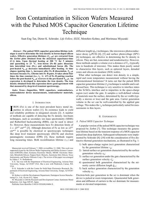
2392 <strong>IEEE</strong> TRANSACTIONS ON ELECTRON DEVICES, VOL. 47, NO. 12, DECEMBER 2000<br />
<strong>Iron</strong> Contam<strong>in</strong>ation <strong>in</strong> Silicon Wafers Measured<br />
<strong>with</strong> <strong>the</strong> Pulsed MOS Capacitor Generation Lifetime<br />
Technique<br />
Suat-Eng Tan, Dieter K. Schroder, Life Fellow, <strong>IEEE</strong>, Motohiro Kohno, and Morimasa Miyazaki<br />
Abstract—The pulsed MOS capacitor generation lifetime technique<br />
is used to determ<strong>in</strong>e <strong>the</strong> iron density <strong>in</strong> boron-doped <strong>silicon</strong><br />
<strong>wafers</strong>. Effective generation lifetimes ( e ) are extracted from<br />
<strong>the</strong> Zerbst plots obta<strong>in</strong>ed from <strong>the</strong> <strong>measured</strong> capacitance-time<br />
(C-t) data. Upon <strong>the</strong>rmal heat<strong>in</strong>g at 200 C for 5 m<strong>in</strong>utes<br />
and quench<strong>in</strong>g to 23 C, iron–boron (Fe–B) pairs dissociate<br />
<strong>in</strong>to <strong>in</strong>terstitial iron (Fe ) and substitutional boron (B). The<br />
post-heated e decreases immediately after heat<strong>in</strong>g. As time<br />
elapses (pair<strong>in</strong>g time <strong>in</strong>creases) after Fe–B dissociation, e<br />
<strong>in</strong>creases because Fe reforms <strong>in</strong>to Fe–B pairs. It takes about four<br />
times <strong>the</strong> time constant (i.e., 4 ) of Fe–B pair<strong>in</strong>g reaction<br />
before <strong>the</strong> post-heated e recovers to <strong>the</strong> pre-heated e .An<br />
expression is developed to determ<strong>in</strong>e <strong>the</strong> iron density. The iron<br />
density obta<strong>in</strong>ed from this expression shows good agreement <strong>with</strong><br />
that <strong>measured</strong> by deep-level transient spectroscopy.<br />
Index Terms—Impurities, MOS capacitors, semiconductors,<br />
semicondutctor device measurements, semiconductor materials,<br />
<strong>silicon</strong>.<br />
I. INTRODUCTION<br />
IRON (Fe) is one of <strong>the</strong> most prevalent heavy metal impurities<br />
<strong>in</strong> <strong>silicon</strong> <strong>wafers</strong> [1]. Its existence leads to yield<br />
and reliability problems <strong>in</strong> <strong>in</strong>tegrated circuits [2]. A number<br />
of methods are capable of detect<strong>in</strong>g <strong>the</strong> Fe density. Ion-beam<br />
techniques, such as secondary ion mass spectrometry (SIMS)<br />
and Ru<strong>the</strong>rford backscatter<strong>in</strong>g (RBS), can be used to detect<br />
Fe. However, <strong>the</strong>se measurements have Fe detection limits of<br />
cm [3]. Although detection of Fe as low as<br />
cm is possible by electrical or spectroscopic techniques<br />
like deep level transient spectroscopy (DLTS) and electron<br />
paramagnetic resonance (EPR) [3], <strong>the</strong>se methods require<br />
long measur<strong>in</strong>g times. Both recomb<strong>in</strong>ation lifetime ( ) and<br />
Manuscript received February 7, 2000; revisedMay 12, 2000. This work was<br />
supported <strong>in</strong> part by <strong>the</strong> Silicon Wafer Eng<strong>in</strong>eer<strong>in</strong>g and Defect Science Consortium<br />
(SiWEDS) (Intel, Komatsu Electronic Metals, MEMC Electronic Materials,<br />
Mitsubishi Silicon, Nippon Steel, Okmetic, Sumitomo Sitix Silicon, Texas<br />
Instruments, and Wacker Siltronic Corp.). The review of this paper was arranged<br />
by Editor J. N. Hollenhorst.<br />
S.-E. Tan was <strong>with</strong> <strong>the</strong> Department of Electrical Eng<strong>in</strong>eer<strong>in</strong>g, Arizona State<br />
University, Tempe, AZ 85287 USA. She is now <strong>with</strong> Wafertech, Camas, WA<br />
USA<br />
D. K. Schroder is <strong>with</strong> <strong>the</strong> Center for Solid State Electronics Research, Department<br />
of Electrical Eng<strong>in</strong>eer<strong>in</strong>g, Arizona State University, Tempe, AZ 85287<br />
USA.<br />
M. Kohno is <strong>with</strong> <strong>the</strong> Development Department, Da<strong>in</strong>ippon Screen Manufactur<strong>in</strong>g<br />
Co., Ltd., Kyoto 612, Japan.<br />
M. Miyazaki is <strong>with</strong> <strong>the</strong> Research and Development Center, Sumitomo Metal<br />
Industries, Ltd, Saga 849-05, Japan.<br />
Publisher Item Identifier S 0018-9383(00)10406-X.<br />
diffusion length ( ) techniques, like microwave photoconductance<br />
decay ( PCD) [4], [5] and surface photovoltage (SPV)<br />
[6] techniques, are effective <strong>in</strong> determ<strong>in</strong><strong>in</strong>g <strong>the</strong> Fe density <strong>in</strong><br />
<strong>silicon</strong>. They are fast, noncontact and nondestructive. However,<br />
<strong>the</strong>se methods sample a volume over a distance of (typically<br />
tens to hundreds of microns). This makes <strong>the</strong>m poorly suited<br />
to characterize th<strong>in</strong> layers, such as epitaxial layers, denuded<br />
zones and <strong>silicon</strong>-on-<strong>in</strong>sulator (SOI) <strong>wafers</strong>.<br />
What o<strong>the</strong>r technique can detect iron density <strong>in</strong> a simple,<br />
rapid and room temperature measurement <strong>with</strong>out hav<strong>in</strong>g <strong>the</strong><br />
aforementioned limitations? It turns out that <strong>the</strong> pulsed MOS<br />
capacitor generation lifetime ( ) technique is suitable and is addressed<br />
here. This technique is very sensitive to <strong>in</strong>terface states<br />
at <strong>the</strong> Si/SiO <strong>in</strong>terface and to impurities <strong>in</strong> <strong>the</strong> space-charge<br />
region (scr) under <strong>the</strong> gate. It samples a well-def<strong>in</strong>ed volume<br />
of materials near <strong>the</strong> surface, determ<strong>in</strong>ed by <strong>the</strong> scr width (typically<br />
a micron or less) and <strong>the</strong> gate area. Carrier generation<br />
volume <strong>in</strong> <strong>the</strong> scr can be well-controlled by <strong>the</strong> applied gate<br />
voltage. This makes <strong>the</strong> technique particularly suited for measurements<br />
<strong>in</strong> th<strong>in</strong> layers.<br />
II. EXPERIMENTS<br />
A. Pulsed MOS Capacitor Technique<br />
A popular version of <strong>the</strong> pulsed MOS capacitor technique was<br />
proposed by Zerbst [7]. This technique measures <strong>the</strong> generation<br />
lifetime based on <strong>the</strong> transient response of a MOS capacitor<br />
pulsed <strong>in</strong>to deep depletion. Subsequent ref<strong>in</strong>ements were implemented<br />
by Schroder [8]–[10] <strong>with</strong> <strong>the</strong> consideration of five dist<strong>in</strong>ctive<br />
<strong>the</strong>rmal generation mechanisms, as illustrated <strong>in</strong> Fig. 1:<br />
1) bulk space-charge region (scr) generation characterized<br />
by <strong>the</strong> generation lifetime ;<br />
2) lateral surface scr generation characterized by <strong>the</strong> surface<br />
generation velocity ;<br />
3) surface scr generation under <strong>the</strong> gate characterized by <strong>the</strong><br />
surface generation velocity ;<br />
4) quas<strong>in</strong>eutral bulk generation characterized by <strong>the</strong> m<strong>in</strong>ority<br />
carrier diffusion length ;<br />
5) back surface generation characterized by <strong>the</strong> generation<br />
velocity .<br />
Electron-hole pair generation <strong>in</strong> <strong>the</strong> scr is dom<strong>in</strong>ant when <strong>the</strong><br />
device is pulsed at room temperature. Quas<strong>in</strong>eutral bulk generation<br />
and diffusion of carriers to <strong>the</strong> scr dom<strong>in</strong>ate for measurements<br />
at elevated temperature.<br />
0018–9383/00$10.00 © 2000 <strong>IEEE</strong>
TAN et al.: IRON CONTAMINATION IN SILICON WAFERS 2393<br />
is related to <strong>the</strong> scr generation parameters,<br />
and <strong>in</strong> Fig. 1. These parameters, as described by <strong>the</strong><br />
terms of and , contribute to which is given as<br />
(3)<br />
Fig. 1. Space-charge region and quas<strong>in</strong>eutral bulk <strong>the</strong>rmal generation<br />
mechanisms of a pulsed MOS capacitor.<br />
<strong>with</strong><br />
The <strong>the</strong>rmal generation rate ( ) of <strong>the</strong> various mechanisms <strong>in</strong><br />
Fig. 1 is <strong>the</strong> negative of <strong>the</strong> change <strong>in</strong> <strong>in</strong>version charge density<br />
( ), given as [11]<br />
where<br />
gate area ( <strong>the</strong> gate radius);<br />
area of <strong>the</strong> lateral scr (for simplicity assum<strong>in</strong>g<br />
<strong>the</strong> lateral scr width is identical to <strong>the</strong> vertical<br />
scr width );<br />
effective m<strong>in</strong>ority carrier diffusion length<br />
[coupl<strong>in</strong>g <strong>the</strong> generation rates of mechanisms<br />
4) and 5) <strong>in</strong> Fig. 1 <strong>in</strong>to ].<br />
For pulsed MOS capacitor measurements, <strong>the</strong> <strong>measured</strong> capacitance-time<br />
(C-t) data are converted <strong>in</strong>to a Zerbst plot [i.e.,<br />
versus ( ) plot] us<strong>in</strong>g <strong>the</strong> follow<strong>in</strong>g<br />
equation [11]<br />
(2)<br />
where<br />
oxide capacitance;<br />
f<strong>in</strong>al (equilibrium) capacitance;<br />
effective generation lifetime;<br />
<strong>the</strong> effective surface generation velocity;<br />
<strong>in</strong>tr<strong>in</strong>sic carrier density;<br />
boron density;<br />
and dielectric constant for SiO and Si, respectively.<br />
The extrapolated <strong>in</strong>tercept<br />
of a<br />
Zerbst plot is a measure of <strong>the</strong> scr width-<strong>in</strong>dependent generation<br />
parameters, , and <strong>in</strong> Fig. 1. These parameters, as<br />
described by <strong>the</strong> terms of and <strong>in</strong> (1), do not contribute<br />
to <strong>the</strong> current <strong>in</strong> space-charge region ( ). The slope<br />
(1)<br />
where<br />
effective generation lifetime <strong>in</strong> <strong>the</strong> spacecharge<br />
region;<br />
bulk scr generation lifetime;<br />
lateral surface generation lifetime.<br />
What is actually <strong>measured</strong> is a mixture of bulk scr and lateral<br />
surface generation lifetimes. In <strong>the</strong> limit of low surface generation<br />
velocity ( – cm/s for well-passivated SiO /Si <strong>in</strong>terfaces),<br />
<strong>the</strong> bulk scr lifetime dom<strong>in</strong>ates <strong>the</strong> surface lifetime<br />
(i. e., and ) and <strong>the</strong> term of ( )<strong>in</strong><br />
e(3) becomes very small and is negligible. We can <strong>the</strong>n rewrite<br />
(3) as<br />
B. Sample Preparation and Measurement Procedure<br />
The test <strong>wafers</strong> were 5-<strong>in</strong> diameter, Czochralski-grown (CZ)<br />
p-type (100) <strong>silicon</strong> <strong>wafers</strong> <strong>with</strong> resistivity 10 -cm. These<br />
<strong>wafers</strong> had an alum<strong>in</strong>um gate contact, 490 Å oxide thickness<br />
and a boron density of cm . The iron density<br />
was determ<strong>in</strong>ed by deep level transient spectroscopy (DLTS)<br />
measurements at room temperature to be cm .<br />
The pulsed MOS capacitor measurements were made <strong>with</strong> an<br />
MDC CSM/W<strong>in</strong> system. The system consists of: 1) a hot chuck<br />
probe station located <strong>with</strong><strong>in</strong> a dark box, 2) an HP 4284A (20<br />
Hz to 1 MHz) Precision LCR meter <strong>with</strong> 0.01 fF resolution, 3)<br />
a temperature controller and 4) a water cool<strong>in</strong>g system used for<br />
fast cool<strong>in</strong>g <strong>the</strong> chuck. Capacitance measurements were carried<br />
out at a frequency of 100 kHz and a small ac signal of 40 mV.<br />
Fig. 2 is an outl<strong>in</strong>e of <strong>the</strong> Fe density detection procedure <strong>in</strong> this<br />
work.<br />
Prior to <strong>the</strong> C-t measurements, <strong>the</strong> as-quenched sample was<br />
stored at room temperature (approximately 23 C) for two<br />
weeks. This allowed a complete transformation of iron from<br />
Fe species to Fe–B pairs. The sample was <strong>in</strong>itially biased<br />
<strong>in</strong>to accumulation and <strong>the</strong>n pulsed <strong>in</strong>to deep depletion. The<br />
recovery time is determ<strong>in</strong>ed by <strong>the</strong> <strong>the</strong>rmal electron-hole pair<br />
(ehp) generation properties of <strong>the</strong> Si substrate and <strong>the</strong> Si/SiO<br />
<strong>in</strong>terface. A set of C-t data is <strong>measured</strong>. The wafer was <strong>the</strong>n<br />
heated to 200 C for 5 m<strong>in</strong>, followed a by quench<strong>in</strong>g to 23 C<br />
on a cold alum<strong>in</strong>um plate. Such a heat treatment dissociates <strong>the</strong><br />
(4)<br />
(5)
2394 <strong>IEEE</strong> TRANSACTIONS ON ELECTRON DEVICES, VOL. 47, NO. 12, DECEMBER 2000<br />
Fig. 3.<br />
The energy levels of Fe and Fe–B pairs <strong>in</strong> p-type <strong>silicon</strong> <strong>wafers</strong>.<br />
Which of <strong>the</strong>se state dom<strong>in</strong>ates depends on <strong>the</strong> temperature ( )<br />
and <strong>the</strong> boron density ( ). At room temperature and boron<br />
densities greater than cm [18], all iron forms pairs <strong>with</strong><br />
boron as Fe–B. Upon heat<strong>in</strong>g at around 200 C for boron densities<br />
less than cm , most of <strong>the</strong> Fe–B pairs dissociate <strong>in</strong>to<br />
Fe and B [18]. As time elapses, <strong>in</strong>terstitial iron Fe reforms<br />
<strong>in</strong>to Fe–B pairs <strong>with</strong> a time constant , given as [19]<br />
(7)<br />
is <strong>the</strong> diffusivity of <strong>the</strong> Fe<br />
species [21], expressed as<br />
(8)<br />
Fig. 2. Procedure to determ<strong>in</strong>e iron density by us<strong>in</strong>g <strong>the</strong> pulsed MOS capacitor<br />
generation lifetime measurement.<br />
<strong>with</strong> as Boltzmann’s constant. The high diffusivity of Fe <strong>in</strong><br />
<strong>silicon</strong> is attributed to <strong>the</strong> difference <strong>in</strong> <strong>the</strong> elastic energies of<br />
<strong>the</strong> tetrahedral sites (T-sites) and hexagonal sites (H-sites) [21].<br />
If cm and K, <strong>the</strong>n m<strong>in</strong><br />
and cm /s accord<strong>in</strong>g to (7) and (8).<br />
The generation lifetime ( ), <strong>the</strong> time to generate one electron-hole<br />
pair (ehp) <strong>the</strong>rmally, depends exponentially on <strong>the</strong> impurity<br />
energy level ( ) and <strong>in</strong>versely on <strong>the</strong> capture cross sections<br />
of electrons ( ) and holes ( ). It is given as [22]<br />
Fe–B pairs <strong>in</strong>to <strong>in</strong>terstitial iron (Fe ) and substitutional boron<br />
(B), but does not lead to a permanent loss of Fe by precipitation<br />
[6]. Dur<strong>in</strong>g <strong>the</strong> process of Fe–B pair dissociation, C-t data<br />
were periodically <strong>measured</strong>. All C-t data <strong>measured</strong> before and<br />
after heat<strong>in</strong>g were converted <strong>in</strong>to Zerbst plots us<strong>in</strong>g equation<br />
(2). The generation lifetimes were extracted from <strong>the</strong> slopes of<br />
<strong>the</strong> Zerbst plots. We will give more detailed discussion on this<br />
extraction method <strong>in</strong> Section IV.<br />
III. THEORETICAL BACKGROUND<br />
<strong>Iron</strong> (Fe) can exist <strong>in</strong> one of <strong>the</strong> two states: ei<strong>the</strong>r <strong>in</strong>terstitial<br />
iron (Fe ) or iron-boron pairs (Fe–B). Fig. 3 depicts <strong>the</strong> various<br />
energy levels of Fe and Fe–B <strong>in</strong> p-type <strong>silicon</strong>. Fe has an energy<br />
level at eV (donor) [12], [13] whereas Fe–B pairs<br />
have two energy levels at eV (donor) [12], [13] and<br />
eV (acceptor) [13]–[15]. The presence of iron affects<br />
<strong>the</strong> generation lifetime [6], [16], [17]. Interstitial iron Fe <strong>with</strong><br />
a deeper energy level is a more active generation site than Fe–B<br />
pairs.<br />
Fe–B pairs are formed by Coulomb attraction and <strong>the</strong>y dissociate<br />
at an elevated temperature, described by<br />
Fe B Fe B (6)<br />
where and are electron<br />
and hole lifetimes. is <strong>the</strong> <strong>the</strong>rmal velocity, and is <strong>the</strong><br />
impurity density.<br />
Dur<strong>in</strong>g <strong>the</strong> dissociation and reformation of Fe–B pairs after<br />
heat<strong>in</strong>g, <strong>the</strong> sum of Fe and Fe–B pair densities ( ) rema<strong>in</strong>s<br />
unchanged at room temperature.<br />
(9)<br />
(10)<br />
<strong>with</strong> and as <strong>the</strong> densities of Fe and Fe–B<br />
at pair<strong>in</strong>g time after heat<strong>in</strong>g. The iron density of our test<br />
samples, as determ<strong>in</strong>ed by DLTS measurements, is ma<strong>in</strong>ly attributed<br />
to Fe–B pairs before heat<strong>in</strong>g ( ). Assum<strong>in</strong>g all<br />
Fe–B pairs totally dissociate <strong>in</strong>to Fe immediately after heat<strong>in</strong>g<br />
( ), we have<br />
(11)<br />
(12)<br />
Under <strong>the</strong> assumptions that all <strong>the</strong> <strong>in</strong>terstitial iron atoms are ionized<br />
fully and <strong>the</strong> reformation of Fe species to Fe–B pairs obey
TAN et al.: IRON CONTAMINATION IN SILICON WAFERS 2395<br />
first-order reaction k<strong>in</strong>etics, <strong>the</strong> Fe density may be expressed<br />
as a function of pair<strong>in</strong>g time as<br />
(13)<br />
where is <strong>the</strong> time constant of <strong>the</strong> Fe–B pair<strong>in</strong>g reaction. Substitut<strong>in</strong>g<br />
(13) <strong>in</strong>to (10), <strong>the</strong> Fe–B density at any given time<br />
after <strong>the</strong>rmal heat<strong>in</strong>g can be expressed as<br />
(14)<br />
Let and be <strong>the</strong> correspond<strong>in</strong>g generation lifetimes<br />
of Fe at eV and Fe–B pairs at eV and<br />
eV energy levels, respectively. From (9)–(14), we<br />
obta<strong>in</strong><br />
Fig. 4. C-t plots of an iron doped p-type <strong>silicon</strong> MOS capacitor before and<br />
after heat<strong>in</strong>g at 200 C for 5 m<strong>in</strong>.<br />
(15)<br />
(16)<br />
(17)<br />
where and are <strong>the</strong> correspond<strong>in</strong>g impurity energy<br />
levels, and <strong>the</strong> correspond<strong>in</strong>g<br />
electron and hole capture cross-sections. Thus, <strong>the</strong> total effective<br />
generation lifetime for Fe and Fe–B becomes<br />
(18)<br />
Fe <strong>with</strong> its energy level near <strong>the</strong> middle of <strong>the</strong> band gap is recognized<br />
as <strong>the</strong> most effective generation lifetime killer [4]–[6].<br />
Under <strong>the</strong> assumption that hole ( ) and electron ( )<br />
capture cross-sections of Fe do not differ too greatly (by a factor<br />
of 100 or less) [22], <strong>the</strong> Fe density immediately after 200 C<br />
heat<strong>in</strong>g can be described as [17]<br />
(19)<br />
<strong>with</strong> as Fe impurity energy level,<br />
and<br />
<strong>the</strong> effective generation lifetimes before<br />
and after 200 C heat<strong>in</strong>g.<br />
IV. RESULTS AND DISCUSSION<br />
Fig. 4 is a plot of <strong>the</strong> <strong>measured</strong> C-t data for a boron-doped <strong>silicon</strong><br />
MOS capacitor before and after heat<strong>in</strong>g at 200 C for 5 m<strong>in</strong>.<br />
Dur<strong>in</strong>g <strong>the</strong> C-t measurements, <strong>the</strong> device is <strong>in</strong>itially biased <strong>in</strong>to<br />
accumulation ( 3 V) and <strong>the</strong>n pulsed <strong>in</strong>to deep depletion<br />
Fig. 5. Correspond<strong>in</strong>g Zerbst plots of Fig. 4 obta<strong>in</strong>ed from (2).<br />
( 3 V). Thermal electron-hole pair generation returns <strong>the</strong><br />
device to equilibrium over time. After about 1400 m<strong>in</strong> pair<strong>in</strong>g<br />
time , <strong>the</strong> pos<strong>the</strong>ated C-t curve co<strong>in</strong>cides <strong>with</strong> <strong>the</strong> preheated<br />
C-t curve, <strong>in</strong>dicat<strong>in</strong>g reformation of all Fe <strong>in</strong>to Fe–B pairs. This<br />
is approximately four times <strong>the</strong> time constant ( m<strong>in</strong>) of<br />
<strong>the</strong> Fe–B pair<strong>in</strong>g reaction, consistent <strong>with</strong> (13) and (14). Longer<br />
times do not change <strong>the</strong> C-t curve. Notice that <strong>the</strong> total C-t measur<strong>in</strong>g<br />
time is kept far below <strong>the</strong> pair<strong>in</strong>g time constant (<br />
m<strong>in</strong>utes) of <strong>the</strong> sample <strong>in</strong> this study.<br />
Us<strong>in</strong>g (2), <strong>the</strong> correspond<strong>in</strong>g Zerbst plots are obta<strong>in</strong>ed from<br />
<strong>the</strong> <strong>measured</strong> C-t data as illustrated <strong>in</strong> Fig. 5. The most useful<br />
part of <strong>the</strong>se plots is <strong>the</strong> l<strong>in</strong>ear region. The portion near <strong>the</strong> orig<strong>in</strong><br />
is when <strong>the</strong> device approaches equilibrium. The curvature at<br />
<strong>the</strong> o<strong>the</strong>r end of <strong>the</strong> l<strong>in</strong>ear region has been ascribed to fieldenhanced<br />
emission from <strong>in</strong>terface and/or bulk traps [23], [24].<br />
The pos<strong>the</strong>ated slope of <strong>the</strong> Zerbst plot decreases as pair<strong>in</strong>g time<br />
<strong>in</strong>creases. At about 1400 m<strong>in</strong>, <strong>the</strong> pos<strong>the</strong>ated l<strong>in</strong>e co<strong>in</strong>cides<br />
<strong>with</strong> <strong>the</strong> preheated l<strong>in</strong>e and rema<strong>in</strong>s constant <strong>with</strong> time.<br />
Effective generation lifetimes ( ) can be extracted from<br />
<strong>the</strong> slopes of <strong>the</strong> l<strong>in</strong>ear regions <strong>in</strong> Fig. 5 accord<strong>in</strong>g to (2). Fig. 6<br />
is a plot of versus pair<strong>in</strong>g time . is m<strong>in</strong>imum<br />
immediately after heat<strong>in</strong>g when dissociation of Fe–B pairs occurs.<br />
As time elapses, <strong>in</strong>creases because Fe reforms <strong>in</strong>to<br />
Fe–B pairs. The changes <strong>in</strong> can be <strong>in</strong>terpreted as follows.<br />
Due to <strong>the</strong> deep energy level of Fe ( 0.4 eV), carriers are
2396 <strong>IEEE</strong> TRANSACTIONS ON ELECTRON DEVICES, VOL. 47, NO. 12, DECEMBER 2000<br />
TABLE I<br />
VALUES OF ELECTRON AND HOLE CAPTURE CROSS-SECTIONS USED TO FIT THE DATA FOR RECOMBINATION (FALSTER et al. [27] AND ZOTH et al. [25]) AND<br />
GENERATION (THIS WORK) FOR Fe AND Fe–B CENTERS. ASSUMING = 5 2 10 cm =10 cm AND BY SUBSTITUTING ( ;t )DATA (ALL<br />
MEASURED AT T =296 K AND OBTAINED FROM FIG. 6)INTO EQUATIONS (15)–(18), , , , CAN BE CALCULATED<br />
Fig. 6. Experimental (po<strong>in</strong>ts extracted from Fig. 5) and calculated (solid l<strong>in</strong>e)<br />
generation lifetimes versus pair<strong>in</strong>g time t after Fe–B pair dissociation.<br />
readily generated immediately after <strong>the</strong> heat<strong>in</strong>g. In comparison,<br />
<strong>the</strong> Fe–B pairs have shallower energy levels. This gives rise to<br />
a relatively <strong>in</strong>efficient carrier generation and <strong>the</strong>refore a longer<br />
lifetime.<br />
The experimental data ( , ) can be well fitted <strong>with</strong> capture<br />
cross-sections for generation at Fe and Fe–B centers. Due<br />
to <strong>the</strong> shallow level, <strong>the</strong> Fe–B center at eV is a less active<br />
generation site compared to <strong>the</strong> o<strong>the</strong>rs (Fe–B at<br />
eV and Fe at eV). Its capture cross sections at room<br />
temperature ( and hole ) are approximately <strong>in</strong> <strong>the</strong> range<br />
of cm from <strong>the</strong> literature. Assum<strong>in</strong>g<br />
cm , cm and by substitut<strong>in</strong>g ( , )<br />
data from Fig. 6, eV, eV (Fe at<br />
eV), eV (Fe–B at eV), eV<br />
(Fe–B at eV), K, cm<br />
and m<strong>in</strong> [from equations (7) and (8)] <strong>in</strong>to (15)–(18), <strong>the</strong><br />
capture cross sections of Fe at eV ( , ) and for<br />
Fe–B at eV ( , ) are obta<strong>in</strong>ed as given <strong>in</strong> Table I.<br />
Although <strong>the</strong>re is some scatter <strong>in</strong> <strong>the</strong> experimental data, <strong>the</strong> general<br />
trend is that predicted by <strong>the</strong>ory. Also shown <strong>in</strong> Table I is a<br />
list of capture cross-sections used to fit <strong>the</strong> data for recomb<strong>in</strong>ation<br />
at Fe and Fe–B centers. These are values derived by Zoth<br />
et al. [25] from SPV measurements and a mixture of published<br />
data [6], [13], [26] as well as fitted values used by Falster et al.<br />
[27]. To check <strong>the</strong> effect of capture cross sections on generation<br />
lifetime, we used different comb<strong>in</strong>ation of and for <strong>the</strong><br />
curve fitt<strong>in</strong>g <strong>in</strong> Fig. 6. Three <strong>in</strong>terest<strong>in</strong>g observations are found<br />
from <strong>the</strong>se curve fitt<strong>in</strong>gs. First, assum<strong>in</strong>g<br />
cm<br />
and<br />
, <strong>the</strong> pre-heated effective generation lifetime<br />
is sensitive to <strong>the</strong> hole capture cross section of<br />
<strong>the</strong> Fe–B 0.29 eV level ( ) whereas <strong>the</strong> post-heated generation<br />
lifetime<br />
is sensitive to <strong>the</strong> electron capture<br />
cross section of <strong>the</strong> Fe 0.4 eV level ( ). Second, assum<strong>in</strong>g<br />
cm and , changes <strong>in</strong> and<br />
by a factor of 10 up or down hardly affect . Thirdly,<br />
changes <strong>in</strong> and (while , , , are constant,<br />
as given <strong>in</strong> Table I) by a factor of 10 up or down hardly affect<br />
. We po<strong>in</strong>t out here that capture cross sections <strong>measured</strong><br />
under recomb<strong>in</strong>ation and generation conditions may differ. Recomb<strong>in</strong>ation<br />
takes place ma<strong>in</strong>ly <strong>in</strong> <strong>the</strong> quas<strong>in</strong>eutral regions of<br />
a device or material <strong>with</strong> low or zero electric field. Generation,<br />
however, takes place <strong>in</strong> <strong>the</strong> space-charge region <strong>with</strong> significant<br />
electric field. Electric field <strong>in</strong>fluences <strong>the</strong> capture cross sections<br />
(capture cross section is a misnomer; it is really an emission<br />
cross section) dur<strong>in</strong>g generation. Typically capture cross sections<br />
are reduced (i.e., emission cross sections are enhanced)<br />
<strong>in</strong> <strong>the</strong> presence of electric fields [23], [28]. An example of <strong>the</strong><br />
capture cross section dependence on electric fields for metal impurities<br />
<strong>in</strong> <strong>silicon</strong> can be found <strong>in</strong> Tasch et al. [29]. In this case,<br />
<strong>the</strong> gold acceptor potential barrier is lowered <strong>in</strong> <strong>the</strong> presence of<br />
electric fields. This resulted <strong>in</strong> an <strong>in</strong>crease of <strong>the</strong> <strong>the</strong>rmal emission<br />
rate and a reduction <strong>in</strong> capture cross sections.<br />
The rate of cool<strong>in</strong>g after heat<strong>in</strong>g at 200 C can affect <strong>the</strong> Fe–B<br />
dissociation. If <strong>the</strong> cool<strong>in</strong>g rate is <strong>in</strong>sufficiently fast, some of <strong>the</strong><br />
dissociated Fe may reform <strong>in</strong>to Fe–B pairs. Table II shows <strong>the</strong><br />
<strong>in</strong>fluence of cool<strong>in</strong>g rates on Fe–B pair dissociation by different<br />
quench<strong>in</strong>g methods, as proven by DLTS and SPV measurements<br />
[6], [17]. In this work, our test sample was cooled quickly by<br />
quench<strong>in</strong>g on a cold alum<strong>in</strong>um (Al) plate after <strong>the</strong>rmal heat<strong>in</strong>g<br />
at 200 C. Hence, we can assume <strong>the</strong> fraction of Fe left after<br />
quench<strong>in</strong>g is approximately <strong>in</strong> <strong>the</strong> range of about 80–90%. In<br />
o<strong>the</strong>r words, only 80–90% of Fe–B pairs are activated to Fe<br />
after heat<strong>in</strong>g and quench<strong>in</strong>g. The 20 to 10% loss of Fe will be<br />
taken <strong>in</strong>to account <strong>in</strong> <strong>the</strong> analysis.
TAN et al.: IRON CONTAMINATION IN SILICON WAFERS 2397<br />
TABLE II<br />
EFFECTS OF COOLING RATES ON Fe–B DISSOCIATION BY DIFFERENT<br />
QUENCHING METHODS AFTER THERMAL HEATING<br />
Substitut<strong>in</strong>g cm ,<br />
cm , eV and K <strong>in</strong>to equation<br />
(19), <strong>the</strong> Fe density can be expressed as<br />
(20)<br />
Assum<strong>in</strong>g that 90% of <strong>the</strong> Fe–B is activated to Fe after heat<strong>in</strong>g<br />
and quench<strong>in</strong>g on a cold Al plate [17], <strong>the</strong> total Fe–B density <strong>in</strong><br />
<strong>the</strong> space charge region is given as<br />
(21)<br />
Similarly, under <strong>the</strong> assumption of 80% of Fe–B pairs activation<br />
to Fe after heat<strong>in</strong>g and quench<strong>in</strong>g [6], we obta<strong>in</strong><br />
(22)<br />
Substitut<strong>in</strong>g s and<br />
s (obta<strong>in</strong>ed from Fig. 6) <strong>in</strong>to<br />
(21), (22) and (22), we f<strong>in</strong>d cm<br />
(assumption: 100%), cm (assumption:<br />
90%) and cm (assumption: 80%),<br />
respectively. These values are quite close to <strong>the</strong> iron density of<br />
cm determ<strong>in</strong>ed by DLTS measurements. Thus,<br />
equation (20) can be used to predict <strong>the</strong> iron density <strong>in</strong> p-type<br />
<strong>silicon</strong> <strong>wafers</strong> (<strong>with</strong> errors less than 15%). The constant of<br />
depends on <strong>the</strong> aforementioned quench<strong>in</strong>g methods.<br />
The important issue is that not only can <strong>the</strong> capture cross<br />
sections of Fe used <strong>in</strong> equations (20)–(22) lead to reasonable<br />
expressions for calculation, but <strong>the</strong>y also fit <strong>the</strong><br />
<strong>measured</strong> effective generation lifetimes <strong>in</strong> Fig. 6 very<br />
well. In o<strong>the</strong>r words, <strong>the</strong> constants of ,<br />
and <strong>in</strong> equations (20)–(22) have been experimentally<br />
verified from both pulsed MOS generation lifetime and DLTS<br />
measurements. A l<strong>in</strong>ear dependence between ( )<br />
and Fe concentration (<strong>measured</strong> by SPV technique) was first<br />
reported by Walz et al. [30]. Obermeier et al. [17] reported<br />
this constant to be . The reason for <strong>the</strong> discrepancy<br />
from our measurements could be <strong>the</strong> difference <strong>in</strong> respective<br />
carrier capture cross sections for iron and iron–boron pairs.<br />
Apart from <strong>the</strong> capture cross sections, ano<strong>the</strong>r parameter that<br />
affects <strong>the</strong> discrepancy <strong>in</strong> constants is <strong>the</strong> surface condition of<br />
<strong>the</strong> wafer under test. To achieve good iron detection precision,<br />
high quality samples <strong>with</strong> low surface generation velocity have<br />
to be used.<br />
The detection limit of iron density depends strongly<br />
on <strong>the</strong> generation lifetime . Suppose<br />
and cm/s <strong>in</strong> our test<br />
sample <strong>with</strong><br />
mm. Accord<strong>in</strong>g to equation (5), an<br />
effective generation lifetime of 2500<br />
s is found. Assume <strong>the</strong> pos<strong>the</strong>ated generation lifetime to<br />
be 10% lower than <strong>the</strong> preheated generation lifetime, i.e.,<br />
. From equations<br />
(20)–(22), we obta<strong>in</strong> detection limits of about<br />
cm , cm and about cm <strong>in</strong> this<br />
work. This limit is set by surface generation. For a surface<br />
<strong>with</strong> lower surface generation velocity, <strong>the</strong> detection limit<br />
is correspond<strong>in</strong>gly reduced. The limit of about cm<br />
shows good agreement <strong>with</strong> <strong>the</strong> experimental results reported<br />
by Kohno et al. [31]. In this case, <strong>the</strong> generation lifetimes<br />
were <strong>measured</strong> <strong>with</strong> <strong>the</strong> metal–<strong>in</strong>sulator-semiconductor (MIS)<br />
and metal–air–<strong>in</strong>sulator-semiconductor (MAIS) methods on<br />
a boron-doped Si before and after 210 C heat<strong>in</strong>g. These<br />
experiments revealed that <strong>the</strong> generation lifetime reduced<br />
immediately after heat<strong>in</strong>g as Fe density was <strong>in</strong>creased due to<br />
<strong>the</strong> dissociation of Fe–B pairs. Both methods were capable of<br />
detect<strong>in</strong>g an iron density down to about cm , consistent<br />
<strong>with</strong> <strong>the</strong> detection limit found <strong>in</strong> this work.<br />
V. SUMMARY<br />
The pulsed MOS capacitor generation lifetime technique can<br />
be used to determ<strong>in</strong>e <strong>the</strong> iron density <strong>in</strong> p-type <strong>silicon</strong> <strong>wafers</strong>.<br />
This technique is particularly suitable for measurements <strong>in</strong> th<strong>in</strong><br />
layers. Upon heat<strong>in</strong>g at 200 C for 5 m<strong>in</strong> and quench<strong>in</strong>g to<br />
23 C, <strong>the</strong> effective generation lifetimes of boron-doped <strong>silicon</strong><br />
MOS capacitor were extracted from <strong>the</strong> Zerbst plots before and<br />
after iron–boron (Fe–B) pair dissociation. An expression has<br />
been developed to determ<strong>in</strong>e <strong>the</strong> iron density. The constant of<br />
<strong>the</strong> expression depends on <strong>the</strong> cool<strong>in</strong>g rate after heat<strong>in</strong>g<br />
which varies <strong>with</strong> different quench<strong>in</strong>g methods. An iron detection<br />
limit of about cm was found <strong>in</strong> this work, consistent<br />
<strong>with</strong> <strong>the</strong> Kohno et al. [31]. The measurements <strong>in</strong> this work were<br />
made on conventional MOS capacitors. They can, of course,<br />
also be implemented by o<strong>the</strong>r space-charge region measurement<br />
techniques. For example, <strong>in</strong> one contactless method, <strong>the</strong> gate<br />
is held about 0.5 m above <strong>the</strong> sample [31]–[33]. In ano<strong>the</strong>r<br />
technique, <strong>the</strong> deep-depleted space-charge region is formed by<br />
a pulsed corona charge [34]. Equally valid are reverse-biased<br />
diode current measurements [11].<br />
REFERENCES<br />
[1] L. Jastrzebski, “An overview of effects of heavy metal <strong>contam<strong>in</strong>ation</strong>,<br />
wafer characteristics and getter<strong>in</strong>g on device/circuit performance,” <strong>in</strong><br />
Semiconductor Silicon: Electrochem. Soc., 1990, pp. 614–627.<br />
[2] K. Honda, T. Nakanishi, A. Ohsawa, and N. Toyokura, “Breakdown <strong>in</strong><br />
<strong>silicon</strong> oxides (II)—Correlation <strong>with</strong> Fe precipitates,” Appl. Phys. Lett.,<br />
vol. 46, pp. 582–584, Mar. 1985.
2398 <strong>IEEE</strong> TRANSACTIONS ON ELECTRON DEVICES, VOL. 47, NO. 12, DECEMBER 2000<br />
[3] B. O. Kolbesen and W. Pamler, “Surface and th<strong>in</strong> film analysis <strong>in</strong> <strong>silicon</strong><br />
technology: Actual and future problems and demands,” Fresenius<br />
Z. Anal. Chem., vol. 333, pp. 561–568, 1989.<br />
[4] T. S. Horanyi, P. Tutto, and C. Kovacsics, “Identification possibility of<br />
metallic impurities <strong>in</strong> p-type <strong>silicon</strong> by lifetime measurement,” J. Electrochem.<br />
Soc., vol. 143, pp. 216–220, Jan. 1996.<br />
[5] A. Kempf et al., “Influence of iron and copper on m<strong>in</strong>ority carrier recomb<strong>in</strong>ation<br />
lifetime <strong>in</strong> <strong>silicon</strong>,” <strong>in</strong> Recomb<strong>in</strong>ation Lifetime Measurements<br />
<strong>in</strong> Silicon, D. C. Gupta, F. R. Bacher, and W. M. Hughes, Eds: Amer.<br />
Soc. Test<strong>in</strong>g and Materials, 1998, vol. ASTM STP 1340, pp. 259–267.<br />
[6] G. Zoth and W. Bergholz, “A fast, preparation-free method to detect iron<br />
<strong>in</strong> <strong>silicon</strong>,” J. Appl. Phys., vol. 67, pp. 6765–6771, June 1990.<br />
[7] M. Zerbst, “Relaxation effects at semiconductor–<strong>in</strong>sulator <strong>in</strong>terfaces”<br />
(<strong>in</strong> German), Z. Angew. Phys., vol. 22, pp. 30–33, May 1966.<br />
[8] D. K. Schroder and H. C. Nathanson, “On <strong>the</strong> separation of bulk and<br />
surface components of lifetime us<strong>in</strong>g <strong>the</strong> pulsed MOS capacitor,” Solid-<br />
State Electron., vol. 13, pp. 577–582, July 1970.<br />
[9] D. K. Schroder, “Bulk and optical generation parameters <strong>measured</strong> <strong>with</strong><br />
<strong>the</strong> pulsed MOS capacior,” <strong>IEEE</strong> Trans. Electron Devices, vol. ED-19,<br />
pp. 1018–1023, Sept. 1972.<br />
[10] , “Effective lifetimes <strong>in</strong> high quality <strong>silicon</strong> devices,” Solid-State<br />
Electron., vol. 27, pp. 247–251, Mar. 1984.<br />
[11] , Semiconductor Material and Device Characterization, 2nd<br />
ed. New York: Wiley, 1998, ch. 7.<br />
[12] L. C. Kimerl<strong>in</strong>g and J. L. Benton, “Electronically controlled reactions of<br />
<strong>in</strong>terstitial iron <strong>in</strong> <strong>silicon</strong>,” Physica B, vol. 116, pp. 297–300, Feb. 1983.<br />
[13] S. D. Bro<strong>the</strong>rton, P. Bradley, and A. Grill, “<strong>Iron</strong> and <strong>the</strong> iron-boron complex<br />
<strong>in</strong> <strong>silicon</strong>,” J. Appl. Phys., vol. 57, pp. 1941–1943, Mar. 1985.<br />
[14] Y. Hayamizu et al., “Temperature dependence of m<strong>in</strong>ority-carrier lifetime<br />
<strong>in</strong> iron-diffused p-type <strong>silicon</strong> <strong>wafers</strong>,” J. Appl. Phys., vol. 69, pp.<br />
3077–3081, Mar. 1991.<br />
[15] A. Kaniava et al., “Recomb<strong>in</strong>ation activity of iron-related complexes<br />
<strong>in</strong> <strong>silicon</strong> studied by temperature dependent carrier lifetime measurements,”<br />
Appl. Phys. Lett., vol. 67, pp. 3930–3932, Dec. 1995.<br />
[16] M. Miyazaki, M. Sano, S. Sumita, and N. Fuj<strong>in</strong>o, “Influence of metal<br />
impurities on leakage current of Si n p diode,” Jpn. J. Appl. Phys., vol.<br />
30, pp. 295–297, Feb. 1991.<br />
[17] G. Obermeier and D. Huber, “<strong>Iron</strong> detection <strong>in</strong> polished and epitaxial<br />
<strong>silicon</strong> <strong>wafers</strong> us<strong>in</strong>g generation lifetime measurements,” J. Appl. Phys.,<br />
vol. 81, pp. 7345–7349, June 1997.<br />
[18] H. Lemke, “Dop<strong>in</strong>g properties of iron <strong>in</strong> <strong>silicon</strong>” (<strong>in</strong> German), Phys.<br />
Stat. Solids, vol. A64, pp. 215–224, Mar. 1981.<br />
[19] L. C. Kimerl<strong>in</strong>g, J. L. Benton, and J. J. Rub<strong>in</strong>, “Transition metal impurities<br />
<strong>in</strong> <strong>silicon</strong>,” <strong>in</strong> Defects and Radiation Effects <strong>in</strong> Semiconductors<br />
1980, ser. Inst. Phys. Conf. Ser. 59, 1981, pp. 217–222.<br />
[20] S. A. McHugo et al., “<strong>Iron</strong> solubility <strong>in</strong> highly boron-doped <strong>silicon</strong>,”<br />
Appl. Phys. Lett., vol. 73, pp. 1424–1426, Sept. 1998.<br />
[21] A. A. Istratov, H. Hieslmair, and E. R. Weber, “<strong>Iron</strong> and its complexes<br />
<strong>in</strong> <strong>silicon</strong>,” J. Appl. Phys., vol. 69, pp. 13–44, Jan. 19899.<br />
[22] D. K. Schroder, “The concept of generation and recomb<strong>in</strong>ation lifetimes<br />
<strong>in</strong> semiconductors,” <strong>IEEE</strong> Trans. Electron Devices, vol. ED-29,<br />
pp. 1336–1338, Aug. 1982.<br />
[23] P. U. Calzolari, S. Graffi, and C. Morandi, “Field-enhanced carrier<br />
generation <strong>in</strong> MOS capacitors,” Solid-State Electron., vol. 17, pp.<br />
1001–1011, Oct. 1974.<br />
[24] K. S. Rabbani, “Investigations on field enhanced generation <strong>in</strong> semiconductors,”<br />
Solid-State Electron., vol. 30, pp. 607–613, June 1987.<br />
[25] G. Zoth, “Aspects of <strong>silicon</strong> <strong>contam<strong>in</strong>ation</strong> control by lifetime measurements,”<br />
<strong>in</strong> Recomb<strong>in</strong>ation Lifetime Measurements <strong>in</strong> Silicon, D.C.<br />
Gupta, F. R. Bacher, and W. M. Hughes, Eds: Amer. Soc. Test<strong>in</strong>g Mater.,<br />
1998, pp. 31–44.<br />
[26] K. Graff and H. Pieper, “The behavior of transition and noble metals<br />
<strong>in</strong> <strong>silicon</strong> crystals,” <strong>in</strong> Semiconductor Silicon 1981, H. R. Huff, R. J.<br />
Kriegler, and Y. Takeishi, Eds. Penn<strong>in</strong>gton, NJ: Electrochem. Soc.,<br />
1981, pp. 331–343.<br />
[27] R. Falster and G. Borionetti, “The application of m<strong>in</strong>ority carrier lifetime<br />
techniques <strong>in</strong> modern CZ <strong>silicon</strong>,” <strong>in</strong> Recomb<strong>in</strong>ation Lifetime Measurements<br />
<strong>in</strong> Silicon, D. C. Gupta, F. R. Bacher, and W. M. Hughes, Eds:<br />
Amer. Soc. Test. Mater., 1998, pp. 226–249.<br />
[28] J. Frenkel, “On <strong>the</strong> pre-breakdown phenomena <strong>in</strong> <strong>in</strong>sulators and electronic<br />
semi-conductors,” Phys. Rev., vol. 54, pp. 647–648, Oct. 1938.<br />
[29] A. F. Tasch Jr. and C. T. Sah, “Recomb<strong>in</strong>ation-generation and optical<br />
properties of gold acceptor <strong>in</strong> <strong>silicon</strong>,” Phys. Rev. B, vol. 1, pp. 800–809,<br />
Jan. 1970.<br />
[30] D. Walz, J. P. Joly, and F. Tardif, “MOS generation lifetime for measur<strong>in</strong>g<br />
metal <strong>contam<strong>in</strong>ation</strong> <strong>in</strong> <strong>silicon</strong>,” <strong>in</strong> Ultraclean Process<strong>in</strong>g of Si<br />
Surfaces, M. Heyns, Ed. Leuven, Belgium: Acco, 1994, pp. 139–142.<br />
[31] M. Kohno et al., “Noncontact measurement of generation lifetime,” Jpn.<br />
J. Appl. Phys., vol. 35, pp. 5539–5544, Oct. 1996.<br />
[32] T. Sakai et al., “Noncontact electrode-free capacitance/voltage measurement<br />
based on general <strong>the</strong>ory of metal-oxide-semiconductor (MOS)<br />
structure,” Jpn. J. Appl. Phys., vol. 32, pp. 4005–4011, Sept. 1993.<br />
[33] S. Hirae et al., “Novel approach to evaluation of charg<strong>in</strong>g on semiconductor<br />
surface by noncontact, electrode-free capacitance/voltage measurement,”<br />
Jpn. J. Appl. Phys., vol. 33, pp. 1823–1830, Apr. 1994.<br />
[34] D. K. Schroder et al., “Corona-oxide-semiconductor device characterization,”<br />
Solid-State Electron., vol. 42, pp. 505–512, Apr. 1998.<br />
Suat-Eng Tan was born <strong>in</strong> Johor, Malaysia. She received<br />
<strong>the</strong> B.S. degree from National Taiwan University,<br />
Taipei, Taiwan, R.O.C., and <strong>the</strong> Ph.D. degree<br />
from National University of S<strong>in</strong>gapore, S<strong>in</strong>gapore,<br />
both <strong>in</strong> electrical eng<strong>in</strong>eer<strong>in</strong>g, <strong>in</strong> 1993 and 1997, respectively.<br />
She conducted research on hot-carrier effects<br />
<strong>in</strong> submicron MOS devices dur<strong>in</strong>g her Ph.D.<br />
study.<br />
After she graduated, she jo<strong>in</strong>ed <strong>the</strong> Department<br />
of Electrical Eng<strong>in</strong>eer<strong>in</strong>g, Arizona State University,<br />
Tempe, as a Post-Doctoral Researcher. Dur<strong>in</strong>g <strong>the</strong><br />
summer of 1999, she was a Visit<strong>in</strong>g Researcher at Mitsubishi Silicon America,<br />
OR. She is currently a Senior Process Integration Eng<strong>in</strong>eer at WaferTech,<br />
Camas, WA. Her current research <strong>in</strong>terests <strong>in</strong>clude ULSI/VLSI device fabrication,<br />
defect studies, characterization and simulation of hot-carrier effects, and<br />
carrier lifetimes <strong>in</strong> semiconductor. She has published more than ten journal and<br />
conference papers <strong>in</strong> <strong>the</strong>se fields.<br />
Dieter K. Schroder (S’61–M’67–SM’78–F’86<br />
–LF’00) received his education at McGill University,<br />
Montreal, PQ, Canada, and at <strong>the</strong> University of<br />
Ill<strong>in</strong>ois, Urbana.<br />
He jo<strong>in</strong>ed West<strong>in</strong>ghouse Research Laboratories<br />
<strong>in</strong> 1968, where he was engaged <strong>in</strong> research on<br />
various aspects of semiconductor devices, <strong>in</strong>clud<strong>in</strong>g<br />
MOS devices, imag<strong>in</strong>g arrays, power devices, and<br />
magnetostatic waves. He spent a year at <strong>the</strong> Institute<br />
of Applied Solid State Physics, Freiburg, Germany<br />
dur<strong>in</strong>g 1978. In 1981 he jo<strong>in</strong>ed <strong>the</strong> Center for Solid<br />
State Electronics Research, Arizona State University, Tempe. His current<br />
<strong>in</strong>terests are semiconductor materials and devices, characterization, low power<br />
electronics, and defects <strong>in</strong> semiconductors. He is <strong>the</strong> author of Advanced MOS<br />
Devices and Semiconductor Material and Device Characterization and has<br />
published over 120 papers.<br />
Applied Physics.<br />
Motohiro Kohno was born <strong>in</strong> Japan, on May 14,<br />
1957. He received <strong>the</strong> B.S. and M.S. degrees <strong>in</strong><br />
electronics eng<strong>in</strong>eer<strong>in</strong>g from Hiroshima University,<br />
Hiroshima, Japan, <strong>in</strong> 1980 and 1982, respectively.<br />
In 1984, he jo<strong>in</strong>ed <strong>the</strong> Da<strong>in</strong>ippon Screen MFG. Co.<br />
Ltd., Kyoto, Japan, where he has been engaged <strong>in</strong> research<br />
and development of noncontact C–V measurement<br />
technique. His current <strong>in</strong>terests are noncontact<br />
techniques for <strong>in</strong>-l<strong>in</strong>e monitor<strong>in</strong>g of <strong>contam<strong>in</strong>ation</strong>.<br />
Mr. Kohno is a member of <strong>the</strong> Japan Society of<br />
Applied Physics.<br />
Morimasa Miyazaki was born <strong>in</strong> Hyogo, Japan, <strong>in</strong><br />
1951. He received <strong>the</strong> B.E. degree from Osaka University<br />
of Education <strong>in</strong> 1974, <strong>the</strong> M.S. degree from<br />
Kyoto University <strong>in</strong> 1977, and <strong>the</strong> Ph.D. degree <strong>in</strong><br />
electronic eng<strong>in</strong>eer<strong>in</strong>g from Okayama University <strong>in</strong><br />
1996.<br />
In 1985, he jo<strong>in</strong>ed Sumitomo Metal Industries,<br />
Saga, Japan, where he has been engaged <strong>in</strong> research<br />
of metal impurities and defects behavior <strong>in</strong> Si semiconductor<br />
material.<br />
Dr. Miyazaki is a member of <strong>the</strong> Japan Society of