Carrier Lifetimes in Silicon - Dieter Schroder - Arizona State University
Carrier Lifetimes in Silicon - Dieter Schroder - Arizona State University
Carrier Lifetimes in Silicon - Dieter Schroder - Arizona State University

Create successful ePaper yourself
Turn your PDF publications into a flip-book with our unique Google optimized e-Paper software.
SCHRODER: CARRIER LIFETIMES IN SILICON 165<br />
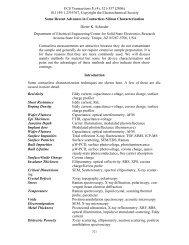
Fig. 10. g versus E T for N T =10 12 cm 03 ; n =5210 014 cm 2 :<br />
Figs. 5 and 10 show clearly that and can be very<br />
different, even for the same impurity and show that the measurement<br />
technique plays an important role when measur<strong>in</strong>g<br />
the lifetime. A measurement technique that determ<strong>in</strong>es the<br />
recomb<strong>in</strong>ation lifetime, such as photoconductance decay or<br />
surface photovoltage, will give a very different answer than the<br />
generation lifetime measured, for example, by the pulsed MOS<br />
capacitor method. This is effectively illustrated <strong>in</strong> Fig. 11<br />
where both and are shown for Fe-contam<strong>in</strong>ated<br />
Si. The effective lifetimes are def<strong>in</strong>ed later. Although there is<br />
a fair amount of scatter <strong>in</strong> the data, is clearly higher than<br />
It is important, obviously, to specify the measurement<br />
method as these figures illustrate. This, however, is not always<br />
done. Furthermore, the generation lifetime is sometimes<br />
referred to as the m<strong>in</strong>ority carrier generation lifetime, creat<strong>in</strong>g<br />
further confusion. Recall that <strong>in</strong> the space-charge region of a<br />
reverse-biased device one cannot speak of a m<strong>in</strong>ority carrier<br />
lifetime.<br />
B. Shockley–Read–Hall Surface Generation Velocity<br />
The surface generation velocity is given by [5]<br />
(13)<br />
It can be thought of as that velocity with which carriers,<br />
generated at the surface or <strong>in</strong>terface, leave that surface.<br />
is proportional to the surface or <strong>in</strong>terface state density through<br />
and def<strong>in</strong>ed <strong>in</strong> (10). In contrast to bulk deep-level impurities<br />
that have discrete energy levels <strong>in</strong> the bandgap, <strong>in</strong>terface<br />
traps or surface states are distributed <strong>in</strong> energy throughout the<br />
semiconductor bandgap. Furthermore, the density of <strong>in</strong>terface<br />
traps usually varies through the bandgap, further complicat<strong>in</strong>g<br />
the analysis and not considered here. Another consideration is<br />
the state of the surface. Generation is highest for a depleted<br />
surface and dim<strong>in</strong>ishes for both accumulated and <strong>in</strong>verted<br />
surfaces. This is most elegantly illustrated with leakage current<br />
measurements of gate-controlled diodes. In this test structure<br />
the semiconductor surface, controlled by a gate, can be accumulated,<br />
depleted, or <strong>in</strong>verted and the resultant leakage current<br />
depends very sensitively on the state of that surface [11].<br />
Aga<strong>in</strong>, the type of recomb<strong>in</strong>ation/generation velocity that is<br />
determ<strong>in</strong>ed depends very much on the measurement technique.<br />
Fig. 11. g and r versus Fe density. For sources of experimental data see<br />
Figs. 12 and 18.<br />
In general, For example, – cm/s for well<br />
passivated SiO Si <strong>in</strong>terfaces, whereas can be 100–1000<br />
cm/s for that same <strong>in</strong>terface. Of course, also depends on<br />
<strong>in</strong>jection level.<br />
IV. EFFECTIVE LIFETIMES<br />
A. Recomb<strong>in</strong>ation Lifetime/Surface Recomb<strong>in</strong>ation Velocity<br />
The bulk recomb<strong>in</strong>ation lifetime itself is <strong>in</strong>dependent of<br />
surface recomb<strong>in</strong>ation. However, the measured recomb<strong>in</strong>ation<br />
lifetime, frequently referred to as the effective recomb<strong>in</strong>ation<br />
lifetime is dependent on surface recomb<strong>in</strong>ation as carriers<br />
recomb<strong>in</strong>e both <strong>in</strong> the bulk as well as at the surface.<br />
can be expressed as [5]<br />
where<br />
the surface lifetime, is given by<br />
is the electron diffusion constant and<br />
a solution of the equation [12]<br />
(14)<br />
(15)<br />
is obta<strong>in</strong>ed from<br />
(16)<br />
where is the sample thickness. In the limits of low or<br />
high surface recomb<strong>in</strong>ation velocity the surface lifetime<br />
becomes<br />
(17)<br />
Equation (14) is plotted <strong>in</strong> Fig. 12 as a function of impurity<br />
density. For impurity densities below about 10 cm<br />
must be very low to be able to measure the true recomb<strong>in</strong>ation<br />
lifetime. If that is not the case, then the effective lifetime can<br />
be much lower than the bulk lifetime. Also shown on Fig. 12<br />
are experimental data for Fe-contam<strong>in</strong>ated Si. Although there<br />
is a fair amount of scatter <strong>in</strong> the data, the general trend is<br />
that predicted by theory. The effective lifetime is <strong>in</strong>versely