<strong>Surface</strong> <strong>voltage</strong> <strong>and</strong> <strong>surface</strong> photo<strong>voltage</strong> (a) (b) 1100 1000 900 5.6 5.4 5.1 Figure 20. Resistivity maps of epitaxial layers determined by ac SV measurements. The values are in ohm cm. The black peripheral ring in (a) is low resistivity (
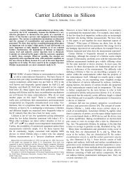
D K <strong>Schroder</strong> Φ (photons/sÂP 2 ) 4 10 9 3 10 9 L n =100 µm 200 150 2 10 9 300 500 1 10 9 1000 0 -400 -200 0 200 400 1/α (µm) (a) 1/Φ (photons/sÂP 2 ) -1 2 10 -9 L n =1000 µm 500 1 10 -9 200 0 0 250 500 750 1000 1/α (µm) (b) Figure 21. Constant <strong>voltage</strong> SPV plots of exact equation <strong>and</strong> approximation. (a) versus 1/α <strong>and</strong> (b) 1/ versus 1/α. The solid lines are the exact calculations (equation (A4)) <strong>and</strong> the dashed lines are the extrapolations. s 1 = 10 4 cm s −1 , s 2 = 10 4 cm s −1 , D n = 30 cm 2 s −1 , V P = 10 mV, R = 0.3, n 0 = 10 5 cm −3 <strong>and</strong> d = 500 µm. light beam, a 1500 µm diffusion length would be measured as 675 µm <strong>and</strong> a 750 µm diffusion length would be measured as 525 µm. For d light − d probe ≈ 2L n,real , the error becomes insignificant [60]. 8.3. Reflectivity The light intensity transmitted into the sample depends on the reflectivity. The reflectivity for bare wafers is reasonably constant with wavelength. However, for oxidized wafers R depends on insulator film thickness <strong>and</strong> on wavelength. Hence the effective photon flux density, eff = (1 − R), must be known for correct interpretation of SPV diffusion length measurements. 8.4. Temperature Temperature causes α to change because the semiconductor b<strong>and</strong> gap is temperature dependent. Higher measurement temperature leads to lower b<strong>and</strong> gap <strong>and</strong> higher α. Hence, if the measurement temperature is higher than the usual room temperature, the value of L n extracted from such SPV measurements will be too high due to the temperature dependence of the absorption coefficient. 8.5. Trapping Trapping centres in the semiconductor capture carriers <strong>and</strong> then release them back to the b<strong>and</strong> from which they were captured. Excess ehps are generated by light. Instead of recombining directly, some electrons are temporarily captured or trapped. They are subsequently re-emitted into the conduction b<strong>and</strong>, <strong>and</strong> finally recombine with the holes. Clearly the electrons ‘live’ longer in this case by the length of time that they are trapped, <strong>and</strong> diffusion length measurements give erroneously high values. Trapping is detected in SPV measurements, for example, by a diffusion length dependence on photon flux density [61] <strong>and</strong> can be much reduced by illuminating the sample with a steady-state background light. The light continually creates ehps, keeping the traps filled, <strong>and</strong> additional ehps will recombine with reduced trapping. 9. Summary <strong>Surface</strong> <strong>voltage</strong> <strong>and</strong> <strong>surface</strong> photo<strong>voltage</strong> measurements are the topic of this review. After a brief history, tracing the basic technique to 1953, the theory of these techniques is developed. In order for a <strong>surface</strong> <strong>voltage</strong> to exist, it is necessary to deposit charge on the sample by some means. This is most commonly done by rinsing the sample in certain solutions or depositing corona charge on it. Rinsing is usually done on bare samples <strong>and</strong> corona charge is deposited on samples covered by insulators. The use of these contactless measurement techniques has broadened from initial application of minority carrier diffusion length measurements to a wide variety of semiconductor characterization, including <strong>surface</strong> <strong>voltage</strong>, <strong>surface</strong> barrier height, flatb<strong>and</strong> <strong>voltage</strong>, oxide thickness, oxide charge density, interface trap density, mobile charge density, oxide integrity, generation lifetime, recombination lifetime <strong>and</strong> doping density. It is likely that this range of application will broaden further. As with all characterization techniques, there are limitations <strong>and</strong> some of these are also discussed. I have chosen to give detailed derivations of the necessary concepts, including liberal use of b<strong>and</strong> diagrams, because this aspect of the technique is rarely discussed in the published literature. Acknowledgments The research leading to this paper was partially funded by the Silicon Wafer Engineering <strong>and</strong> Defect Science Consortium (SiWEDS) (Intel, Komatsu Electronic Metals, MEMC Electronic Materials, Mitsubishi Silicon, Okmetic, Nippon Steel, SEH America, Sumitomo Sitix Silicon, Texas Instruments, <strong>and</strong> Wacker Siltronic Corp.). I wish to thank them for their support. I also wish to thank the anonymous reviewer for a thorough review <strong>and</strong> for thoughtful comments, allowing the manuscript to be improved. Appendix A. DC excitation We first consider the p-type semiconductor of figure A1(a). It is a wafer of thickness d, reflectivity R, minority carrier lifetime τ, minority carrier diffusion coefficient D, minority carrier diffusion length L <strong>and</strong> <strong>surface</strong> recombination velocities s 1 <strong>and</strong> s 2 at the front <strong>and</strong> back <strong>surface</strong>s. Monochromatic light of R28