You also want an ePaper? Increase the reach of your titles
YUMPU automatically turns print PDFs into web optimized ePapers that Google loves.
IMPACT 8.4 / 12.4 / 16.4 / 24.4<br />
IMPACT 8.4X / 12.4X / 16.4X / 24.4X<br />
Mixing Console<br />
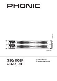
IMPACT 8.4X<br />
ENGLISH<br />
User’s <strong>Manual</strong>
IMPORTANT SAFETY INSTRUCTIONS<br />
The apparatus shall not be exposed to dripping or splashing and that no objects filled with liquids, such as vases,<br />
shall be placed on the apparatus. The MAINS plug is used as the disconnect device, the disconnect device shall<br />
remain readily operable.<br />
Warning: the user shall not place this apparatus in the confined area during the operation so that the mains switch<br />
can be easily accessible.<br />
1. Read these instructions before operating this<br />
apparatus.<br />
2. Keep these instructions for future reference.<br />
3. Heed all warnings to ensure safe operation.<br />
4. Follow all instructions provided in this document.<br />
5. Do not use this apparatus near water or in locations<br />
where condensation may occur.<br />
6. Clean only with dry cloth. Do not use aerosol or liquid<br />
cleaners. Unplug this apparatus before cleaning.<br />
7. Do not block any of the ventilation openings. Install<br />
in accordance with the manufacturer’s instructions.<br />
8. Do not install near any heat sources such as radiators,<br />
heat registers, stoves, or other apparatus (including<br />
amplifiers) that produce heat.<br />
9. Do not defeat the safety purpose of the polarized or<br />
grounding-type plug. A polarized plug has two blades<br />
with one wider than the other. A grounding type plug<br />
has two blades and a third grounding prong. The wide<br />
blade or the third prong is provided for your safety. If<br />
the provided plug does not fit into your outlet, consult<br />
an electrician for replacement of the obsolete outlet.<br />
10. Protect the power cord from being walked on or<br />
pinched particularly at plug, convenience receptacles,<br />
and the point where they exit from the apparatus.<br />
CAUTION<br />
RISK OF ELECTRIC SHOCK<br />
DO NOT OPEN<br />
CAUTION: TO REDUCE THE RISK OF ELECTRIC SHOCK,<br />
DO NOT REMOVE COVER (OR BACK)<br />
NO USER SERVICEABLE PARTS INSIDE<br />
REFER SERVICING TO QUALIFIED PERSONNEL<br />
The lightning flash with arrowhead symbol, within an<br />
equilateral triangle, is intended to alert the user to the<br />
presence of uninsulated “dangerous voltage” within the<br />
product’s enclosure that may be of sufficient<br />
magnitude to constitute a risk of electric shock to persons.<br />
The exclamation point within an equilateral triangle is intended<br />
to alert the user to the presence of important operating<br />
and maintenance (servicing) instructions in the literature<br />
accompanying the appliance.<br />
WARNING: To reduce the risk of fire or electric shock, do<br />
not expose this apparatus to rain or moisture.<br />
CAUTION: Use of controls or adjustments or performance<br />
of procedures other than those specified may result in<br />
hazardous radiation exposure.<br />
11. Only use attachments/accessories specified by the<br />
manufacturer.<br />
12. Use only with a cart, stand, tripod, bracket, or<br />
table specified by the manufacturer, or sold with<br />
the apparatus. When a cart is used, use caution<br />
when moving the cart/apparatus<br />
combination to avoid injury from tipover.<br />
13. Unplug this apparatus during lighting<br />
storms or when unused for long<br />
periods of time.<br />
14. Refer all servicing to qualified service personnel.<br />
Servicing is required when the apparatus has been<br />
damaged in any way, such as power-supply cord or<br />
plug is damaged, liquid has been spilled or objects<br />
have fallen into the apparatus, the apparatus has<br />
been exposed to rain or moisture, does not operate<br />
normally, or has been dropped.
IMPACT 8.4 / 12.4 / 16.4 / 24.4<br />
IMPACT 8.4X / 12.4X / 16.4X / 24.4X<br />
Mixing Console<br />
TABLE OF CONTENTS<br />
INTRODUCTION......................................................................................................4<br />
FEATURES..............................................................................................................4<br />
BASIC SETUP.........................................................................................................5<br />
Getting Started..................................................................................................5<br />
Channel Setup..................................................................................................5<br />
MAKING CONNECTIONS.......................................................................................6<br />
Connecting Panel..............................................................................................6<br />
Rear Panel........................................................................................................7<br />
Main Mixing Panel.............................................................................................7<br />
CONTROLS AND SETTINGS..................................................................................8<br />
Rear Panel........................................................................................................8<br />
Channel Controls..............................................................................................8<br />
Digital Effect Engine..........................................................................................9<br />
Tape In Section................................................................................................10<br />
Master Control Section...................................................................................10<br />
DIGITAL EFFECT TABLE......................................................................................13<br />
APPLICATION........................................................................................................14<br />
SPECIFICATIONS..................................................................................................16<br />
DIMENSIONS........................................................................................................18<br />
BLOCK DIAGRAM.................................................................................................19<br />
Phonic reserves the right to improve or alter any information suppied within this document without prior notice.<br />
V1.2 JUL 05, 2006
INTRODUCTION<br />
Thank you for choosing one of Phonic’s many quality<br />
compact mixers. The Impact mixing consoles - designed<br />
by the same talented engineers that have created a<br />
variety of mixers fantastic in style and performance in<br />
the past - display similar proficiency that previous Phonic<br />
products have shown; with more than a few refinements,<br />
of course.<br />
With a total of 8 models in the Impact series, the Impact<br />
8.4, Impact 12.4, Impact 16.4, Impact 24.4, Impact 8.4<br />
X, Impact 12.4 X, Impact 16.4 X, and Impact 24.4 X,<br />
all with varying inputs yet displaying the same efficacy,<br />
you have no doubt purchased a mixer that will not only<br />
proove ideal for your application, but will outlast many<br />
others.<br />
We know how eager you are to get started - wanting<br />
to get the mixer out and hook it all up is probably your<br />
number one priority right now - but before you do, we<br />
strongly urge you to take a look through this manual.<br />
Inside, you will find important facts and figures on the<br />
set up, use and applications of your brand new mixer. If<br />
you do happen to be one of the many people who flatly<br />
refuse to read user manuals, then we just urge you to at<br />
least glance at the Instant Setup section. After reading<br />
through the manual, please store it in a place that is easy<br />
for you to find, because chances are there is something<br />
you missed the first time around.<br />
FEATURES<br />
• Audiophile-Quality & ultra low noise<br />
• Mono channels with inserts and phantom<br />
power<br />
• 2 stereo channels with 4-band EQ<br />
• 10, 14, 18, 26 mic preamps on Impact 8.4/8.4X,<br />
12.4/12.4X, 16.4/16.4X, 24.4/24.4X<br />
• 3-band EQ with swept mid-range plus low cut<br />
on each mono channel<br />
• 18dB/oct, 75Hz low cut filter on each mono<br />
channels<br />
• 4 aux sends, aux 1 & 2 with XLR and 1/4" output<br />
jacks<br />
• 2 stereo aux returns, each with effect to monitor<br />
• Pad on mono channels to handle difficult signals<br />
• Main Stereo and Mono output with XLR and<br />
1/4" jacks<br />
• Mono output with variable low pass filter for<br />
subwoofer speaker<br />
• Tape input can be routed to aux 1 and aux 2<br />
• Handy mini-stereo I/O for MD, MP3 player/recorder<br />
• Built-in switching power supply with universal<br />
connector, 100-240VAC, 50/60Hz<br />
• Optional Rack-mounting kit for Impact 8.4 and<br />
Impact 8.4 X only, model name ER8IM<br />
• Impact X models further feature 32-bit DSP digital<br />
multi-effect processor with 99 programs<br />
<br />
IMPACT 8.4/12.4/16.4/24.4/8.4X/12.4X/16.4X/24.4X
BASIC SETUP<br />
Getting Started<br />
1. Ensure all power is turned off on the Impact Mixer.<br />
To totally ensure this, the AC cable should not be<br />
connected to the unit.<br />
2. All faders and level controls should be set at the<br />
lowest level and all channels switched off to ensure<br />
no sound is inadvertently sent through the outputs<br />
when the device is switched on. All levels should<br />
be altered to acceptable degrees after the device is<br />
turned on.<br />
3. Plug all necessary instruments and equipment into<br />
the device's various inputs as required. This may<br />
include line signal devices, as well as microphones<br />
and/or guitars, keyboards, etc.<br />
4. PTurn the gain of the selected channel to a degree<br />
that allows the audio level shown in the level meter<br />
to sit around 0 dB, ensuring it never reaches 7 dB..<br />
5. Plug the supplied AC cable into the AC inlet on the<br />
back of the device ensuring the local voltage level is<br />
identical to that required on your device.<br />
6. Plug the supplied AC cable into a power outlet of a<br />
suitable voltage.<br />
7. Turn the power switch on.<br />
Channel Setup<br />
1. To ensure the correct audio levels of each input<br />
channel is selected, every channel should first be<br />
switched off and all faders set to 0.<br />
2. Choose the channel that you wish to set the level of<br />
and ensure that channel has a signal sent to it similar<br />
to the signal that will be sent when in common use.<br />
For example, if the channel is using a microphone,<br />
then you should speak or sing at the same level the<br />
performer normally would during a performance. If<br />
a guitar is plugged into that channel, then the guitar<br />
should also be used as it normally would be.<br />
3. Press the PFL button of the channel, allowing you to<br />
see the audio properties in the level meter.<br />
4. Turn the gain of the selected channel to a degree<br />
that allows the audio level shown in the level meter<br />
to sit around 0 dB, ensuring it never reaches 7 dB.<br />
5. This channel is now ready to be used; you can stop<br />
making the audio signal and disengage the PFL<br />
button.<br />
6. You should now select the next channel to set and go<br />
back to follow steps 1 through 6.<br />
IMPACT 8.4/12.4/16.4/24.4/8.4X/12.4X/16.4X/24.4X
MAKING CONNECTIONS<br />
Connecting Panel<br />
1. XLR Jacks<br />
These jacks accept XLR inputs for balanced signals.<br />
They can be used in conjunction with microphones<br />
such as professional condenser, dynamic or ribbon<br />
microphones - with standard XLR male connectors.<br />
With low noise preamplifiers, these inputs serve for<br />
crystal clear sound replication.<br />
NB. When using an unbalanced microphone, please ensure phantom<br />
power is switched off. However, when using condenser microphones<br />
the phantom power should be activated.<br />
2. Line In Jacks<br />
These balanced inputs accept 1/4" TRS and 1/4"<br />
TS line inputs for the addition of various music<br />
instruments – such as keyboards, drum machines,<br />
electric guitars, as well as a variety of other electric<br />
instruments.<br />
3. Insert Jacks<br />
The primary use for these<br />
TRS phone jacks is for<br />
the addition of external<br />
devices, such as dynamic<br />
processors or equalizers,<br />
to the corresponding<br />
mono input channel. This<br />
will require a Y cord that can send and receive signals<br />
of the mixer to and from an external processor. The<br />
tip of the TRS jack will send the signal from the input<br />
channel, and the ring will return the signal back to the<br />
mixer (the sleeve is the grounding).<br />
5. Stereo Returns<br />
The 1/4” TS Stereo Return inputs are for the return of<br />
audio to the Impact mixer, processed by an external<br />
signal processor. If really needed, they can also<br />
be used as additional stereo inputs. The feed from<br />
these inputs can be adjusted using the Stereo Return<br />
controls on the face of the mixer. When connecting<br />
a monaural device to the AUX Return inputs, simply<br />
plug a 1/4" phone jack into the left (mono) input, and<br />
the signal will appear in the right as well.<br />
6. Auxiliary (AUX) 1 and 2 Outputs<br />
These balanced XLR jacks and unbalanced 1/4" TS<br />
phone jacks are the final output of line-level signal<br />
fed from the corresponding auxiliary send mixing<br />
buses, and are best suited for use with external effect<br />
processors or stage monitors. Feeding the output<br />
from the Auxiliary outs to an amplifier - and possibly<br />
an equalizer - and then to a floor monitor speaker<br />
allows artists to monitor their own instruments or<br />
vocals whilst performing.<br />
7. EFX (Effect) Sends<br />
These 1/4” TS outputs are the final output from the<br />
EFX send mixing bus. This feed may be used to connect<br />
to an external digital effect processor or even<br />
to an amplifier and speakers, depending on your desired<br />
settings.<br />
4. Stereo Channels<br />
The two stereo channels on the Impact mixers<br />
include XLR Mic inputs and 1/4” TS phone jacks.<br />
They can be used in conjunction with various stereo<br />
devices, such as synthesizers and keyboards. Also,<br />
by connecting a mono signal to the left phone jack,<br />
the Impact automatically doubles the signal over to<br />
the right channel. This is known as jack normalizing.<br />
<br />
IMPACT 8.4/12.4/16.4/24.4/8.4X/12.4X/16.4X/24.4X
8<br />
Rear Panel<br />
8. Foot Switch Jacks (Impact X only)<br />
This port is for the inclusion of a foot switch (nonlatchable),<br />
used to remotely adjust properties of the<br />
Impact X’s built-in Digital Effects Engine. Using a<br />
footswitch with this jack will allow users to mute and<br />
un-mute the Digital Effects.<br />
9. Control Room / Phones<br />
These two 1/4" Phone Jack outputs feed the signal<br />
altered by the Control Room level control on the face<br />
of the mixer. This output has extensive use, as it can<br />
be used to feed the signal from the mixer to an active<br />
monitor, for the monitoring of the audio signal from<br />
within a booth, among many other possible uses.<br />
10. Mono / Subwoofer Output<br />
This male XLR and 1/4" TS output feeds a monaural<br />
signal of the Main L-R signals combined, as adjusted<br />
by the accompanying level control. This is ideal for<br />
use with a mono sound system, or for the addition<br />
of a subwoofer to your set of speakers, adding more<br />
punch to low frequency sounds.<br />
11. Main Outputs<br />
These outputs will output the final stereo line level<br />
signal sent from the main mixing bus. The primary<br />
purpose of the two male XLR jacks and 1/4" phone<br />
jacks is to send the main left and right output signal to<br />
external devices, which may include power amplifiers<br />
(and in-turn, a pair of speakers), other mixers, as well<br />
as a wide range of other possible signal processors<br />
(equalizers, crossovers, etcetera).<br />
12. 12V Lamp<br />
This XLR socket allows you to attach a 12 Volt (7<br />
Watt) gooseneck lamp, allowing better visability in<br />
areas with poor light.<br />
13. Power Connector<br />
This is for the addition of an AC<br />
power cable, allowing power to be<br />
supplied to the mixer. Please use<br />
the power cable that is included<br />
with this mixer only. The Fuse<br />
holder, located below the AC<br />
Power connector, is, of course,<br />
for the Impact’s fuse. If the fuse<br />
happens to blow, open the holder<br />
cover, and replace the fuse with a<br />
suitable replacement (as indicated<br />
underneath the power connector).<br />
Main Mixing Panel<br />
14. Tape Inputs<br />
The first of these<br />
inputs accommodates<br />
RCA cables<br />
from such devices<br />
as tape and CD<br />
players. In addition<br />
to these inputs,<br />
however, Phonic has incorporated a mini stereo port<br />
for the inclusion of mini disc (MD), portable CD, and<br />
MP3 players (such as the Apple iPod), as well as laptop<br />
computers. The line from this feed is directed to<br />
the Tape In mixing bus, which users are able to feed<br />
to the Control Room, AUX 1 and 2 or Main L/R mixing<br />
buses.<br />
15. Record Outputs<br />
As with the Tape In ports, these outputs will accommodate<br />
RCA cables, able to be fed to a variety of recording<br />
devices. Also included are mini stereo ports<br />
for the addition of recording devices such as MD<br />
players and laptop computers.<br />
16. Headphones Output<br />
This output port is best suited for use<br />
with headphones, allowing monitoring<br />
of the mix. The audio level of this<br />
output is controlled using the Control<br />
Room / Phones control on the front<br />
panel’s master section.<br />
IMPACT 8.4/12.4/16.4/24.4/8.4X/12.4X/16.4X/24.4X
CONTROLS AND SETTINGS<br />
Rear Panel<br />
17. Power Switch<br />
This switch is used to turn the mixer<br />
on and off. Ensure you turn all level<br />
controls down before activating.<br />
Channel Controls<br />
18. Low Cut Filter (75 Hz)<br />
This button, located on all mono<br />
channels, will active a high-pass<br />
filter that reduces all frequencies<br />
below 75 Hz at 18 dB per octave,<br />
helping to remove any unwanted<br />
ground noise or stage rumble.<br />
19. PAD Button (Stereo Channels Only)<br />
This button, located on channels the final 4 mono<br />
channsl of all Impact mixers, attenuates the input<br />
signal of the Mic or Line inputs by 20 dB. This gives<br />
a greater dynamic range to the input, allowing inputs<br />
with higher-level signals to be used without the<br />
possibility of clipping.<br />
20. Gain Control<br />
This controls the sensitivity of the input signal of the<br />
Line/Microphone input of mono channels. The gain<br />
should be adjusted to a level that allows the maximum<br />
use of the audio, while still maintaining the quality of<br />
the feed. This can be accomplished by adjusting it to<br />
a level that will allow the peak indicator occasionally<br />
illuminate or slightly lower than this.<br />
21. High Frequency Control<br />
This control is used to give a shelving boost or cut<br />
of ±15 dB to high frequency (12 kHz) sounds. This<br />
will adjust the amount of treble included in the audio<br />
of the channel, adding strength and crispness to<br />
sounds such as guitars, cymbals, and synthesizers.<br />
22. Middle Frequency Control<br />
This control is used to provide a peaking style of<br />
boost and cut to the level of middle frequency sounds<br />
at a range of ±15 dB. The Impact mixer also provides<br />
a sweep control, allowing you to select a center<br />
frequency between 100 Hz and 8 kHz. Changing<br />
middle frequencies of an audio feed can be rather<br />
difficult when used in a professional audio mix, as<br />
it is usually more desirable to cut middle frequency<br />
sounds rather than boost them, soothing overly harsh<br />
vocal and instrument sounds in the audio.<br />
Stereo channels differ slightly, in that they feature a<br />
High Mid and Low Mid control for adjusting Middle<br />
Frequency sounds with set frequencies of 3 kHz and<br />
800 Hz.<br />
23. Low Frequency Control<br />
This control is used to give a shelving boost or cut<br />
of ±15 dB to low frequency (80 Hz) sounds. This will<br />
adjust the amount of bass included in the audio of the<br />
channel, and bring more warmth and punch to drums<br />
and bass guitars.<br />
24. AUX Controls<br />
These two AUX controls alters the signal level that<br />
is being sent to the auxiliary 1 and 2 mixing buses,<br />
the signal of which is suitable for connecting stage<br />
monitors, allowing artists to listen to the music<br />
that is being played, or to fed to an external effect<br />
processors.<br />
25. EFX 1 and 2<br />
These two controls adjust the level of audio sent<br />
from the channel to the EFX 1 and 2 mixing buses.<br />
The EFX 2 signal is also sent to the built-in digital<br />
effects processor, allowing users to apply effects to<br />
the signal.<br />
<br />
IMPACT 8.4/12.4/16.4/24.4/8.4X/12.4X/16.4X/24.4X
26. Pan/Balance Controls<br />
This alternates the degree or level of audio that the<br />
left and right side of the main mix should receive. On<br />
mono channels, the PAN control will adjust the level<br />
that the left and right should receive (pan), where as<br />
on a stereo channel, adjusting the BAL control will<br />
attenuate the left or right audio signals accordingly<br />
(balance).<br />
27. Mute Button<br />
This button mutes the channel, effectively stopping<br />
all audio fed into the inputs from being send to the<br />
Main L/R mixing bus, as well as the AUX 1, AUX 2,<br />
EFX 1 and EFX 2 mixing buses. This indicated just<br />
below the button (labeled Peak) will be illuminated<br />
when the channel is muted.<br />
28. Peak Indicator<br />
This LED indicator (which doubles as a mute<br />
indicator) will illuminate when the channel hits high<br />
peaks, 6 dB before overload occurs. It is best to<br />
adjust the channel level control so as to allow the<br />
PEAK indicator to light up on regular intervals only.<br />
This will ensure a greater dynamic range of audio.<br />
This indicator also doubles as a Mute indicator, when<br />
the channel's mute button is engaged.<br />
29. Sig Indicator<br />
This LED indicator shows when the input level<br />
reaches -20 dBu, basically showing when a signal is<br />
received by the corresponding channel.<br />
30. PFL Button<br />
The PFL - or Pre-Fader Listen - button is pushed to<br />
allow the signal of a channel to be sent to the CTRL<br />
RM/PHONES mix (pre-fader, post-EQ), for use with<br />
either headphones or studio monitors. This allows<br />
easier setting of the input gain and tracking of audio<br />
by sound engineers. The Sig LED above the button<br />
will illuminate when PFL is activated.<br />
31. Channel Level Control<br />
This 60 mm fader will alter the signal level that is<br />
sent from the corresponding channel to the Main L/R<br />
mixing bus.<br />
Digital Effect Engine<br />
The following refers to Impact X models only.<br />
32. Digital Effect Display<br />
This 2-digital numeric display shows the program<br />
number that is currently applied to your EFX audio<br />
signal. When you rotate the Program control, you can<br />
scroll through different program numbers; however<br />
the display will revert back to the original program if<br />
a new program is not selected within a few seconds.<br />
For a list of available effects, please observe the<br />
Digital Effect Table.<br />
33. Sig and Clip Indicators<br />
Located within the Digital Effect Display are Clip<br />
and Sig LEDs. The Sig LED will light up when any<br />
signal is received by the effect processor, and the<br />
Clip LED will light up shortly before excessive signals<br />
are dynamically clipped. If the Clip LED lights up too<br />
often, it may be advisable to turn down one or all EFX<br />
controls on input channels to ensure the signal level<br />
is not too high.<br />
34. Program Control<br />
This control is used to scroll through the various<br />
effects. Turning the control clockwise will allow users<br />
to ascend into higher program numbers, and turning<br />
it counter-clockwise will allow users to descend<br />
into lower program numbers. Pushing this control<br />
will apply the new effect. When a tap-delay effect<br />
is selected, pressing this control will allow users to<br />
select the tap-delay time.<br />
By pushing the button several times, the effect<br />
processor interprets the time between last two<br />
pushes and remembers this as the delay time, until<br />
the button is pushed again (this is kept, even after<br />
the power is turned off). When the tap delay effect<br />
is selected, a small LED will flash within the digital<br />
effect display window at the selected intervals.<br />
IMPACT 8.4/12.4/16.4/24.4/8.4X/12.4X/16.4X/24.4X
35. To Aux 1 and 2 Controls<br />
These controls allow<br />
users to adjust the<br />
signal level that is<br />
being sent from the<br />
Effects Engine to<br />
the auxiliary 1 and<br />
2 mixing buses,<br />
the signal of which<br />
is suitable for<br />
connecting stage<br />
monitors, allowing<br />
artists or engineers<br />
to listen to the music<br />
that is being played.<br />
36. Mute Button<br />
This button mutes<br />
the EFX channel,<br />
effectively stopping<br />
the signal processed<br />
by the built-in Effects<br />
Engine from being<br />
sent to the Main L/R<br />
mixing bus.<br />
37. PFL Button<br />
The PFL – or Pre-Fader Listen – button is pushed<br />
to allow the signal of the Effects Engine to be sent<br />
to the CTRL RM / PHONES mix. This allows easier<br />
tracking of audio by sound engineers.<br />
38. DSP Effects Fader<br />
This 60mm fader will alter the signal level that is sent<br />
from the Effects Engine to the Main L/R mix.<br />
41. To AUX 1 and 2 Controls<br />
These controls allow users to adjust the signal level<br />
of the Tape In that is sent to the auxiliary 1 and 2<br />
mixing buses.<br />
Master Control Section<br />
42. Stereo Return To AUX 1 and 2 Controls<br />
These controls adjust the pre-fader level of the signal<br />
from the Stereo Return controls to the corresponding<br />
AUX mixing buses for effect-to-monitor sends.<br />
43. Stereo Return Level Controls<br />
These rotary control will alter the signal level that is<br />
sent from the Stereo Retuns to the Main L/R mix.<br />
44. Stereo Return PFL Buttons<br />
The PFL - or Pre-Fader Listen - buttons are pushed<br />
to allow the Stereo Return signals to be sent to the<br />
Control Room / Phones mix (pre-fader, post-EQ), for<br />
use with either headphones or studio monitors. This<br />
allows easier tracking of audio by sound engineers.<br />
45. AUX 1 and 2 Master Controls<br />
These 60 mm fader will alter the signal level that is<br />
sent from the AUX 1 and 2 to their corresponding<br />
outputs. Both faders are accompanied by AFL (or<br />
After-Fader Listen) buttons, allowing users to send<br />
the post-fader signal to the Control Room / Phones<br />
mixing bus.<br />
Tape In Section<br />
39. Level Control<br />
This controls the level of the signal received through<br />
the Tape In mixing bus, to be sent to the Control<br />
Room / Phones and/or Main L/R mixing buses, as<br />
selected by the user.<br />
40. CTRL RM and MAIN Buttons<br />
These buttons allow users to send the Tape In signal<br />
to these particular mixes. Sending the Tape In<br />
signal to the Control Room mixing bus is useful in<br />
monitoring of the signal, whereas sending it to the<br />
Main L/R allows users to combine the Tape In signal<br />
with the main mix.To avoid any unwanted feedback,<br />
don’t press the MAIN button down when the Record<br />
Out signal is returned to the Mixer through the Tape<br />
Inputs.<br />
10 IMPACT 8.4/12.4/16.4/24.4/8.4X/12.4X/16.4X/24.4X
46. Phantom Power Button and Indicator<br />
When this button is pushed in, +48V<br />
of Phantom Power is activated for all<br />
microphone inputs, allowing condenser<br />
microphones (well, the ones that don’t use<br />
batteries) to be used on these channels.<br />
Activating Phantom Power will be<br />
accompanied by an illuminated LED above<br />
the button. Before turning Phantom Power<br />
on, turn all level controls to a minimum to avoid<br />
the possibility of a ghastly popping sound from the<br />
speakers.<br />
NB. Phantom Power should be used in conjunction with balanced<br />
microphones. When Phantom Power is engaged, single ended<br />
(unbalanced) microphones and instruments should not be used<br />
on the Mic inputs. Phantom Power will not cause damage to most<br />
dynamic microphones, however if unsure, the microphone’s user<br />
manual should be consulted.<br />
48. Mono Channel Controls<br />
The 60 mm faders is the final level control for the<br />
Mono mixing bus, the signal of which is sent to the<br />
Mono / Subwoofer output on the rear of the Impact.<br />
The included AFL button allows users to send the<br />
post-fader Mono signal to the Control Room mixing<br />
bus.<br />
A Low Pass Filter has been included to cut unwanted<br />
high frequency sounds of the mono output at a rate<br />
of 12 dB per octave, for a clearer bass sound when<br />
using subwoofers. The switch turns the Low Pass<br />
Filter on and off, whereas the accompanying control<br />
adjusts the cut-off frequency between 60 and 160<br />
Hz.<br />
49. Control Room / Phones Control<br />
This control is used to adjust the audio level<br />
of the Control Room and Phones feeds, for<br />
use in the monitoring and tracking of audio.<br />
The signal is then sent to the Control Room<br />
outputs on the rear of the Impact mixer, as<br />
well as the Phones jack on the face of the<br />
mixer.<br />
Typically, the signal sent to the Control Room and<br />
Phones mixing buses will be the Main L and R signal,<br />
however if any AFL (After-fader listen) buttons are<br />
pushed, they will take precedent over the Main L<br />
and R signal. If, however, a PFL (Pre-fader listen) is<br />
pushed, that will be the signal heard instead of either<br />
the AFL or Main L and R signals (as shown in the<br />
table below).<br />
Priority<br />
High<br />
Medium<br />
Low<br />
Signal<br />
From PFL<br />
From AFL<br />
Main L/R<br />
47. EFX Send 1 and 2 Master Controls<br />
These rotary controls adjust the final level of the EFX<br />
1 and 2 signals (as taken from the EFX controls on<br />
each channel strip), the audio of which is sent to the<br />
corresponding EFX sends. Also accompanying the<br />
EFX Send controls is an AFL button, allowing users<br />
to send the post-fader signal to the Control Room /<br />
Phones mixing bus. The EFX 2 master control also<br />
determines the final level of the audio sent to the<br />
built-in Effects processor of the Impact X mixer.<br />
IMPACT 8.4/12.4/16.4/24.4/8.4X/12.4X/16.4X/24.4X<br />
11
50. Level Meter<br />
These 12 segment level meters give an accurate<br />
indication the level of the Main left and right audio<br />
signals. The 0 dB indicator illuminates is approximately<br />
equal to an output level of +4 dBu (balanced), and the<br />
PEAK indicator illuminates about 1.5 dB before the<br />
signal is dynamically clipped. To make the maximum<br />
use of audio, set the various level controls so that it<br />
sits steadily around 0 dB to make full use of audio,<br />
while still maintaining fantastic clarity.<br />
If any PFL or AFL buttons are activated, the Main L/R<br />
Level Meter will display the properties of the Control<br />
Room / Phones signal instead.<br />
51. PFL/AFL Indicator<br />
The PFL/AFL indicator on the top of this meter is bicolored,<br />
and illuminates green when a PFL switch is<br />
active and red for an AFL. Due to the fact that any<br />
PFL has priority over any AFL (see section 54), if<br />
both an AFL and PFL are activated, only the green<br />
PFL indicator will illuminated and processed by the<br />
CTRL RM/PHONES control area.<br />
52. Power Indicator<br />
The Power Indicator will light up when the power of<br />
the mixer is on; in case you weren’t too sure.<br />
53. Main L/R Faders<br />
These fader are the final level control for the Main<br />
Left and Right audio feeds, sent to the Main Left and<br />
Right outputs on the rear of the device. When pushed<br />
all the way up, the Main L/R fader provides 10 dB of<br />
gain to the signal, and when set all the way down, the<br />
signal is effectively muted.<br />
12 IMPACT 8.4/12.4/16.4/24.4/8.4X/12.4X/16.4X/24.4X
DIGITAL EFFECT TABLE<br />
NO PROGRAM NAME PARAMETER SETTING<br />
ROOM REV-TIME EARLY LEVEL<br />
00 COMPACT ROOM 1 0.05 100<br />
01 COMPACT ROOM 2 0.4 0<br />
02 SMALL ROOM 1 0.45 100<br />
03 SMALL ROOM 2 0.6 90<br />
04 MID ROOM 1 0.9 100<br />
05 MID ROOM 2 1 50<br />
06 BIG ROOM 1 1.2 100<br />
07 TUNNEL 3.85 100<br />
HALL REV-TIME EARLY LEVEL<br />
08 JAZZ CLUB 0.9 90<br />
09 SMALL HALL 1 1.5 72<br />
10 SMALL HALL 2 1.75 85<br />
11 SPRING HALL 1.9 98<br />
12 MID HALL 1 2.3 100<br />
13 MID HALL 2 2.45 80<br />
14 RECITAL HALL 2.7 96<br />
15 BIG HALL 2 3.3 88<br />
PLATE REV-TIME HPF<br />
16 SMALL PLATE 0.9 0<br />
17 TAIL PLATE 1.2 20<br />
18 MID PLATE 1 1.3 0<br />
19 MID PLATE 2 2.2 0<br />
20 REVERSE PLATE 2.25 42<br />
21 LONG PLATE 1 2.6 80<br />
22 LONG PLATE 2 3 625<br />
23 LONG PLATE 3 4.2 0<br />
DELAY-1(stereo) DELAY AVERG. R-LEVEL<br />
24 SHORT DELAY 1 0.07 60<br />
25 SHORT DELAY 2 0.14 60<br />
26 PING PONG DELAY 0.11 55<br />
27 MID DELAY 1 0.15 55<br />
28 MID DELAY 1 0.3 60<br />
29 SHORT DELAY 1 (MONO) 0.06 100<br />
30 MID DELAY 1 (MONO) 0.13 100<br />
31 LONG DELAY 1 (MONO) 0.18 100<br />
CHORUS LFO DEPTH<br />
32 SOFT CHORUS 0.2 56<br />
33 SOFT CHORUS 2 0.5 70<br />
34 SOFT CHORUS 3 0.8 75<br />
35 WARM CHORUS 1.8 85<br />
36 WARMER CHORUS 1 3.2 80<br />
37 WARMER CHORUS 2 5.2 45<br />
38 WARMER CHORUS 3 7.8 52<br />
39 HEAVY CHORUS 9.6 48<br />
FLANGER LFO DEPTH<br />
40 CLASSIC FLANGER 1 0.1 44<br />
41 CLASSIC FLANGER 2 0.3 63<br />
42 GENTLE FLANGER 0.6 45<br />
43 WARM FLANGER 1.6 60<br />
44 MODERN FALANGER 1 2 85<br />
45 MODERN FALANGER 2 2.8 80<br />
46 DEEP FALANGER 1 4.6 75<br />
47 DEEP FALANGER 2 10 60<br />
PHASER LFO DELAY<br />
48 CLASSIC PHASER 1 0.1 3.6<br />
49 CLASSIC PHASER 2 0.4 2.6<br />
50 COOL PHASER 1.4 0.7<br />
51 WARM PHASER 3.2 0.3<br />
52 HEAVY PHASER 1 5 1.2<br />
53 HEAVY PHASER 2 6 2.8<br />
54 WILD PHASER 1 7.4 0.8<br />
55 WILD PHASER 2 9.6 4.8<br />
NO PROGRAM NAME PARAMETER SETTING<br />
PAN SPEED TYPE<br />
56 SLOW PAN 0.1 R-->L<br />
57 SLOW PAN 1 0.1 RL<br />
58 SLOW PAN 2 0.4 R-->L<br />
59 MID SHIFT 0.8 RL<br />
60 MID SHIFT 1 1.2 L-->R<br />
61 MID SHIFT 2 1.8 L-->R<br />
62 MID SHIFT 3 1.8 R-->L<br />
63 FAST MOVE 3.4 RL<br />
TREMOLO SPEED MODE-TYPE<br />
64 LAZY TREMOLO 0.8 TRG<br />
65 VINTAGE TREMOLO 1.5 TRG<br />
66 WARM TREMOLO 2.8 TRG<br />
67 WARM TREMOLO 1 4.6 TRG<br />
68 HOT TREMOLO 6.8 TRG<br />
69 HOT TREMOLO 1 9.6 TRG<br />
70 CRAZY TREMOLO 1 15 TRG<br />
71 CRAZY TREMOLO 2 20 TRG<br />
DELAY+REV REV DELAY-1<br />
72 DELAY+REV 1 1 1<br />
73 DELAY+REV 2 2 2<br />
74 DELAY+REV 3 3 3<br />
75 DELAY+REV 4 4 4<br />
76 DELAY+REV 5 5 5<br />
77 DELAY+REV 6 6 6<br />
78 DELAY+REV 7 7 7<br />
79 DELAY+REV 8 8 8<br />
CHORUS+REV REV CHORUS<br />
80 CHORUS+REV 1 1 1<br />
81 CHORUS+REV 2 2 2<br />
82 CHORUS+REV 3 3 3<br />
83 CHORUS+REV 4 4 4<br />
84 CHORUS+REV 5 5 5<br />
85 CHORUS+REV 6 6 6<br />
86 CHORUS+REV 7 7 7<br />
87 CHORUS+REV 8 8 8<br />
FLANGER+REV REV FLANGER<br />
88 FLANGER+REV 1 1 1<br />
89 FLANGER+REV 2 2 2<br />
90 FLANGER+REV 3 3 3<br />
91 FLANGER+REV 4 4 4<br />
92 FLANGER+REV 5 5 5<br />
93 FLANGER+REV 6 6 6<br />
94 FLANGER+REV 7 7 7<br />
95 FLANGER+REV 8 8 8<br />
GATED-REV RELEASE REV<br />
96 GATED-REV-1 9 0.02 TAIL PLATE<br />
97 GATED-REV-2 10 0.2 TAIL PLATE<br />
98 GATED-REV-1 9 0.02 REVERSE PLATE<br />
99 GATED-REV-2 10 0.5 REVERSE PLATE<br />
TAP DELAY FB LEVEL RANGE<br />
A0 TAP DELAY 0 100mS - 2.7S<br />
A1 TAP DELAY 10 100mS - 2.7S<br />
A2 TAP DELAY 20 100mS - 2.7S<br />
A3 TAP DELAY 30 100mS - 2.7S<br />
A4 TAP DELAY 40 100mS - 2.7S<br />
A5 TAP DELAY 50 100mS - 2.7S<br />
A6 TAP DELAY 60 100mS - 2.7S<br />
A7 TAP DELAY 70 100mS - 2.7S<br />
A8 TAP DELAY 80 100mS - 2.7S<br />
TEST TONE FREQUENCY SHAPE<br />
T0 LOW FREQUENCY 100Hz SINEWAVE<br />
T1 MID FREQUENCY 1kHz SINEWAVE<br />
T2 HIGH FREQUENCY 10kHz SINEWAVE<br />
PN PINK NOISE 20Hz~20kHz<br />
IMPACT 8.4/12.4/16.4/24.4/8.4X/12.4X/16.4X/24.4X<br />
13
APPLICATION<br />
PA OR LIVE EVENT SETUP<br />
14 IMPACT 8.4/12.4/16.4/24.4/8.4X/12.4X/16.4X/24.4X
CHURCH SETUP<br />
IMPACT 8.4/12.4/16.4/24.4/8.4X/12.4X/16.4X/24.4X<br />
15
SPECIFICATIONS<br />
Inputs<br />
IMPACT 8.4(X) IMPACT 12.4(X) IMPACT 16.4(X) IMPACT 24.4(X)<br />
Balanced Mic / Line channel 8 12 16 24<br />
Stereo channel with mic<br />
preamp<br />
2 2 2 2<br />
Stereo Aux Returns 2 2 2 2<br />
2T Input<br />
Outputs<br />
Main L/R Stereo<br />
Main Mono<br />
Aux sends<br />
Rec Out<br />
Mini stereo and stereo RCA<br />
2 x 1/4” TS, Unbal. & 2 x XLR<br />
1 x 1/4” TS, Unbal. & 1 x XLR<br />
4, 4x 1/4” TS Unbal & 2x XLR<br />
Mini stereo and stereo RCA<br />
CTRL RM L/R 2 x 1/4” TS 2 x 1/4” TS 2 x 1/4” TS 2 x 1/4” TS<br />
Phones 1 1 1 1<br />
Channel Strips 10 14 18 26<br />
Aux Sends 4 4 4 4<br />
Pan/Balance Control Yes Yes Yes Yes<br />
Channel On/Mute Yes Yes Yes Yes<br />
Channel Solo(PFL) with<br />
metering<br />
LED indicators<br />
Yes Yes Yes Yes<br />
Mute/Peak, Signal/PFL<br />
Volume Controls 60mm fader 60mm fader 60mm fader 60mm fader<br />
Master Section<br />
Aux Send Masters 4 4 4 4<br />
Master Aux Send Solo(AFL) 4 4 4 4<br />
Stereo Aux Returns 2 2 2 2<br />
Effects Return to Monitor 3 3 3 3<br />
Faders (60 mm)<br />
Metering<br />
Efx Rtn, Aux 1, Aux 2, Mono, Main L/R<br />
Number of Channels 2 2 2 2<br />
Segments 11 11 11 11<br />
Phantom Power Supply +48V DC +48V DC +48V DC +48V DC<br />
Switches Master Master Master Master<br />
Effect Processor<br />
(32-bit DSP)<br />
Frequency Response (Mic input to any output)<br />
Impact X Models only: 100 effects with tap delay control<br />
32/40-BIT DSP with test tone and foot switch(effect on/off)<br />
20Hz ~ 60KHz +0/-1 dB +0/-1 dB +0/-1 dB +0/-1 dB<br />
20Hz ~ 100KHz +0/-3 dB +0/-3 dB +0/-3 dB +0/-3 dB<br />
Crosstalk (1KHz @ 0dBu, 20Hz to 20KHz bandwidth, channel in to main L/R outputs)<br />
Channel fader down, other<br />
channels at unity<br />
S/N ratio, ref to +4” not<br />
98145.451<br />
Microphone Preamp E.I.N.<br />
(150 ohms terminated, max<br />
gain)<br />
THD (Any output, 1KHz @<br />
+14dBu, 20Hz to 20KHz,<br />
channel inputs)<br />
CMRR (1 KHz @ -60dBu,<br />
Gain at maximum)<br />
Maximum Level<br />
>90 dB >90 dB >90 dB >90 dB<br />
DIMENSIONS<br />
measurements are shown in mm / inches<br />
IMPACT 8.4(X) IMPACT 12.4(X) IMPACT 16.4(X) IMPACT 24.4(X)<br />
X (mm/inches) 440/17.3 572 / 22.5 704 / 27.7 968 / 38.1<br />
Y (mm/inches) 510/20 642 / 25.3 774 / 30.5 1038 / 40.9<br />
18 IMPACT 8.4/12.4/16.4/24.4/8.4X/12.4X/16.4X/24.4X
BLOCK DIAGRAMS<br />
IMPACT 8.4/12.4/16.4/24.4/8.4X/12.4X/16.4X/24.4X<br />
19
6103 Johns Road #7