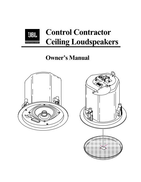
Control Contractor Ceiling Loudspeakers - JBL Professional
Control Contractor Ceiling Loudspeakers - JBL Professional
Control Contractor Ceiling Loudspeakers - JBL Professional

You also want an ePaper? Increase the reach of your titles
YUMPU automatically turns print PDFs into web optimized ePapers that Google loves.
<strong>Control</strong> <strong>Contractor</strong><br />
<strong>Ceiling</strong> <strong>Loudspeakers</strong><br />
Owner’s Manual
Table of Contents<br />
Product Description......................................................................................... 2<br />
Product Feature Identification......................................................................... 3<br />
Installation Preparations.................................................................................. 4<br />
Step-By-Step Installation and Wiring............................................................. 6<br />
Painting the Speaker...................................................................................... 15<br />
Safety Agency Compliance........................................................................... 16<br />
Maintenance .................................................................................................. 16<br />
Replacement Parts......................................................................................... 17<br />
Contacting <strong>JBL</strong>.............................................................................................. 17<br />
1
Thank you for purchasing <strong>JBL</strong> <strong>Control</strong> <strong>Contractor</strong> ceiling loudspeakers.<br />
Read through this manual to familiarize yourself with the features, applications and<br />
precautions before you use these products.<br />
Product Descriptions<br />
The <strong>JBL</strong> <strong>Control</strong> <strong>Contractor</strong> ceiling loudspeakers utilize innovative design and<br />
materials to provide premium level performance from compact in-ceiling speakers.<br />
CONTROL 24C & 24CT – Most compact of the <strong>JBL</strong> ceiling speakers, the <strong>Control</strong><br />
24C contains a coaxially mounted 4” woofer and ¾” titanium-coated tweeter,<br />
providing high-fidelity full-range sound over an extremely wide coverage area. The<br />
optional <strong>Control</strong> 24CT includes a multi-tap transformer for 70V or 100V systems.<br />
CONTROL 26C & 26CT – The <strong>Control</strong> 26C is a powerhouse ceiling speaker<br />
containing a coaxially mounted 6.5” woofer and ¾” titanium-coated tweeter, able to<br />
deliver maximum sound level over a wide coverage area. The optional <strong>Control</strong> 26CT<br />
includes a multitap transformer for a 70V or 100V line distribution system.<br />
CONTROL 19CS & 19CST Subwoofer – The unique Nested Chamber design and<br />
Linear Dynamics port allows powerful low-frequency reinforcement from a<br />
compact in-ceiling enclosure. The <strong>Control</strong> 19CS is an ideal addition to any system,<br />
resulting in full-fidelity high level sound. The optional <strong>Control</strong> 19CST includes a<br />
special subwoofer-band transformer for use on 70V or 100V line distribution systems.<br />
2
Product Feature Identification<br />
(<strong>Control</strong> 24C Shown)<br />
Steel Backcan<br />
Loudspeaker<br />
Di<br />
Tap Selector (on T-versions)<br />
Attachment Screws<br />
Strain Relief Fitting<br />
Removable Locking Input Connector<br />
Seismic Tab<br />
(secondary support point)<br />
Terminal Cover Plate Assembly<br />
Rotating Mounting Tabs<br />
Perforated Press-In Grille<br />
<strong>JBL</strong> Logo<br />
3
Installation Preparations<br />
The entire installation can be accomplished, if necessary, without requiring access<br />
above the ceiling. Bracketry for use with either suspended ceilings or sheetrock<br />
ceilings is included. The speaker is held securely in place via mounting ears which<br />
lock into place. Inputs are attached to a removable locking connector (included)<br />
which can be prewired before installing the speaker for ultra-fast snap-on installation.<br />
OPTIONAL PRE-INSTALLATION BRACKETS<br />
IN MOST CASES, NO BRACKETS OTHER THAN THE ONES INCLUDED WITH<br />
YOUR SPEAKER ARE REQUIRED. Everything needed for most installations of<br />
these loudspeakers is provided with your <strong>Control</strong> <strong>Contractor</strong> ceiling speaker.<br />
However, a particular procedure that is sometimes used for installation into sheet rock<br />
(typically gypsum board) can be facilitated by the use of <strong>JBL</strong>’s optional preinstallation<br />
brackets before the sheetrock is installed. The preinstallation bracket provides a<br />
bracket to which wiring can be tied behind the sheetrock and it can function as a<br />
cutout template when many cutouts are to be made in a production-line style<br />
installation. Two types of pre-installation brackets are available from <strong>JBL</strong><br />
<strong>Professional</strong> as optional accessories:<br />
1) The optional NEW-CONSTRUCTION BRACKET is made of flat sheetmetal,<br />
with wings to attach to the building structure. Holes are drilled for nails or screws at<br />
16 inches (406 mm) and 24 inches (610 mm) on-center. Additional holes can be<br />
drilled by the installer at other spacings up to a maximum of 24-3/4 inches (630 mm)<br />
apart. Sheet rock installs over the bracket, and the bracket provides a template for<br />
blind cutout of the hole in the sheet rock. The sheet rock is typically cut with a routertype<br />
cutting tool, using the bracket ring as a cutout guide.<br />
Figure 1:<br />
Optional New -Construction Bracket<br />
4
2) The optional PLASTER-RING BRACKET (or “mud ring”) contains a circular<br />
offset, forming a edge guide for sheet rock plastering. The bracket has wings that<br />
attach to the building structure. Sheet rock is typically either precut or cut with a<br />
rotary cutting tool using the outside of the plaster ring circle as a guide. The sheet<br />
rock hole is then plastered (or “mudded”) up to the ring to create a seamless cutout.<br />
Figure 2:<br />
Optional Plaster Ring Bracket<br />
Model<br />
New<br />
Construction<br />
Bracket<br />
Plaster-Ring<br />
Bracket<br />
<strong>Control</strong> 24C & 24CT MTC-24NC MTC-24MR<br />
<strong>Control</strong> 26C & 26CT MTC-26NC MTC-26MR<br />
<strong>Control</strong> 19CS & 19CST MTC-19NC MTC-19MR<br />
USING INCLUDED C-BRACKET WITH SHEETROCK<br />
For most installations, the INCLUDED C-shaped backing plate to provides adequate<br />
reinforcement to the ceiling material, spreading out the clamping force from the tab<br />
clamps.<br />
CUTOUT SIZES<br />
Packaged with the speakers are cardboard cutout templates for scribing the cutout hole<br />
onto your ceiling surface.<br />
Model<br />
<strong>Control</strong> 24C & 24CT<br />
<strong>Control</strong> 26C & 26CT<br />
<strong>Control</strong> 19CS & 19CST<br />
Cutout Size<br />
(diameter)<br />
168 mm (6.6 in)<br />
220 mm (8.75 in)<br />
305 mm (12.0 in)<br />
5
STEP-BY-STEP<br />
INSTALLATION AND WIRING<br />
The installation system has been designed so that the entire installation can be<br />
accomplished from beneath the ceiling, for instances when access above the tile is not<br />
possible or practical. However, in some cases it may be easier with removable ceiling<br />
tiles to access from both the top and bottom of the ceiling tile during various phases of<br />
the installation.<br />
Step 1 – Cut the Hole. Cutout the hole size either by tracing the cardboard cutout<br />
template or with a circular cutter set to the cutout sizes listed above. Pull the wiring<br />
through the cutout hole.<br />
Figure 3:<br />
Hole Cutout<br />
Step 2 – Insert Backing Hardware Through the Hole. Packaged with the speakers<br />
are two types of backing hardware – a C-shaped backing-plate bracket and two tile<br />
rails.<br />
Suspended <strong>Ceiling</strong>s – Insert the C-plate through the hole cut in the ceiling tile.<br />
Place the C-plate around the hole with the tabs located as shown on Figure 4.<br />
Insert the tile rails through the cut hole in the ceiling tile. Snap the two rails into the<br />
two tabs in the C-plate and align the rails so that the ends extend OVER the T-<br />
channel grid on the side of the tile. Secure the rails onto the C-bracket tabs by<br />
inserting a screw though each tab into the rail. This can all be accomplished from<br />
below the ceiling tile, if necessary.<br />
! "#<br />
ALL included support brackets – C-plate and tile rails -- MUST be used<br />
when installing into suspended ceiling tiles.<br />
6
Figure 4:<br />
C-Bracket and Tile Rail<br />
Positioning on <strong>Ceiling</strong> Tile<br />
Tile Rails: The tile rails are designed to fit either standard 24-inch wide tiles or 600-mm wide tiles.<br />
The tile rail pieces do NOT physically attach to the T-grid struts. Instead, the inverted-V shape at the<br />
ends of the rails sit OVER the T-grid strut. During normal operation, the rails are supported by the edge<br />
of the tile. In the unlikely even that the tile comes out or falls apart, the ends of the support rails are<br />
designed to catch onto the T-grid, providing secure support to hold the loudspeaker assembly in place.<br />
Vibration Reduction: These loudspeakers can generate substantial vibration, which can cause buzzing<br />
of the ceiling materials or structure. Depending on the character of the ceiling tile and structure, the<br />
installer might need to place neoprene or other dampening material under the tile rails or the edges of<br />
the tiles to eliminate rattles.<br />
Cutout Placement: The tile rails are pre-punched with attachment holes along their length. Placement<br />
is not limited to the center of the tile as is the case with many other tile rail support systems.<br />
Non-Suspended <strong>Ceiling</strong> Types – The C-bracket can be optionally used by itself to<br />
shore up the ceiling material and to spread out the clamping force from the tab<br />
clamps. Insert the C-plate through the cut hole in the ceiling and place it on the<br />
back side of the hole before inserting the speaker.<br />
Step 3 – Connect the Wiring to the Removable Locking Connector – Connect the<br />
wiring to the removable locking connector that is INCLUDED with the speaker by<br />
stripping the insulation back about 5 mm (about 3/16 inch), inserting the bare end of<br />
wire into the connector and screwing down the hold-down screw until tight using a<br />
small flatblade screwdriver. Tighten any unused screws to avoid vibration.<br />
Figure 5:<br />
Connecting Wires to<br />
Removeable Locking Connector<br />
7
Guide to the Pins for Connection -- The removable locking input connector<br />
contains 4 terminals, as marked on the connector. The pin functions are listed on<br />
the label located on the terminal cover plate.<br />
CONNECTION<br />
1 2 3 4<br />
+ –<br />
+ –<br />
IN IN<br />
Loop<br />
Thru<br />
Loop<br />
Thru<br />
Figure 6: Connector Pins<br />
Pins 2 & 3 are the “+” and “-” inputs to the loudspeaker. Pins 2 & 3 are looped to<br />
pins 1 & 4, respectively (Pin 1 connects to Pin 2 and Pin 3 connects to Pin 4) inside<br />
the speaker. Pins 1 & 4 are intended as loop-through connections to subsequent<br />
loudspeakers. There are two possible hookup schemes for connecting subsequent<br />
speakers, determined by the desired result from the circuit whenever this speaker’s<br />
connector gets disconnected during troubleshooting:<br />
Paralleling Input Terminals -- Connect the wire pair of the subsequent<br />
speaker to pins 2 & 3 (in parallel with the input wire pair). Whenever the<br />
connector is pulled out of the speaker for troubleshooting, subsequent speakers<br />
will stay connected. This can be useful during troubleshooting to be able to<br />
disconnect a single loudspeaker at a time. In this hookup scheme, no wires get<br />
connected to pins 1 & 4.<br />
Figure 7:<br />
Paralleling Input Terminals<br />
1 2 3 4<br />
From Amplifier or<br />
Previous Speaker<br />
+<br />
–<br />
–<br />
+<br />
To Subsequent<br />
Speakers<br />
Figure 8:<br />
Parallel System<br />
Hookup Diagram<br />
1 2 3 4 1 2 3 4 1 2 3 4<br />
+<br />
–<br />
To<br />
Subsequent<br />
Speakers<br />
+ –<br />
Power Amplifier<br />
Speaker 1 Speaker 2 Speaker 3<br />
8
Using Loop-Through Terminals (Pins 1 & 4) -- By connecting the wire pair of<br />
the subsequent speaker to pins 1 & 4, then all subsequent speakers will be<br />
disconnected when this speaker’s connector is disconnected during for<br />
troubleshooting,. This can be useful as a way to isolate problems to a section of<br />
the distributed line while leaving the wires attached to the connector.<br />
Figure 9:<br />
Using Loop-<br />
Through Terminals<br />
1 2 3 4<br />
From Amplifier or<br />
Previous Speaker<br />
+<br />
–<br />
–<br />
+<br />
To Subsequent<br />
Speakers<br />
Figure 10:<br />
Loop-Through<br />
System Hookup<br />
Diagram<br />
1 2 3 4 1 2 3 4 1 2 3 4<br />
+<br />
–<br />
To<br />
Subsequent<br />
Speakers<br />
+ –<br />
Power Amplifier<br />
Speaker 1 Speaker 2 Speaker 3<br />
Choose whichever hookup pattern accommodates your installation best.<br />
Step 4 – Plug connector into connector socket in the speaker’s terminal cup.<br />
Figure 11:<br />
Plugging Connector Into<br />
Connector Socket<br />
9
Step 5 – Tighten the Strain Relief Fitting & Close the Terminal Cover<br />
First, remove the horizontal screw indicated in the drawing below.<br />
Figure 12:<br />
Opening the<br />
Strain-Relief Fitting<br />
Next, loosen the screws holding the fitting’s sliding pieces onto the input-terminal<br />
cover by about a half turn. Run the wires through the opening in the fitting.<br />
Figure 13:<br />
Running Wires<br />
Through Opening<br />
In Strain Relief<br />
Fitting<br />
10
The strain relief can be tightened in two ways, choose whichever is best for your<br />
application:<br />
a) Tightening onto plenum cable or bare wire -- Slide the wiring through the<br />
strain relief fitting on the terminal cover plate. In the case of bare wire and<br />
plenum cable it is often possible to provide acceptable strain relief force by<br />
simply tightening the screws holding the sliding strain relief onto the terminal<br />
cover plate. To achieve a tight fit, use a clamping mechanism (such as slipjoint<br />
pliers) to hold the strain relief pieces together while tightening the hold-down<br />
screws.<br />
It is optional to reinsert the horizontal screw that was previously removed and to<br />
tighten the two horizontal screws, clamping the wire securely between them.<br />
Figure 14:<br />
Tightening Fitting<br />
Onto Plenum Cable (shown)<br />
Or Bare Wire<br />
11
) Tightening onto flexible or hard conduit – The supplied fitting<br />
accommodates up to 3/8 inch (9.5mm) flexible conduit. Slide the wiring<br />
through the strain relief fitting on the terminal cover plate. Insert the conduit<br />
into the strain relief fitting. Reinsert the horizontal screw that was previously<br />
removed. Use the two horizontal screws that clamp the fitting together,<br />
clamping the conduit securely between them.<br />
Figure 15:<br />
Tightening Fitting<br />
Onto Conduit<br />
Using an Alternate Fitting – The existing strain relief fitting accommodates many<br />
common fitting requirements. Sometimes, alternate fittings are required, such as<br />
for larger diameter conduit or to meet specific code requirements.<br />
In these cases, the existing fitting can be easily replaced with a number of available<br />
off-the-shelf fittings. Simply remove the existing fitting by unscrewing the two<br />
hold-down screws, exposing a 7/8 inch (22mm) knockout hole. Install the alternate<br />
fitting.<br />
<br />
Always use the proper fitting in accordance with your area’s<br />
building codes and regulations.<br />
Close the Terminal Cover – Close the hinged terminal cover and secure it in place<br />
with the hold-down screw.<br />
12
Step 6 – Insert the Speaker Into the <strong>Ceiling</strong> and Tighten.<br />
Insert the speaker into the ceiling as far as it goes, until the front baffle rim touches the<br />
ceiling.<br />
Figure 16:<br />
Inserting Speaker<br />
Into <strong>Ceiling</strong><br />
Turn the attachment screws to tighten the mounting tabs, by using the following<br />
directions: IMPORTANT -- For each attachment screw, FIRST turn ½ turn<br />
COUNTER-CLOCKWISE to release the mounting tab from its guide.<br />
Then tighten the mounting tabs by turning the screw CLOCKWISE until tight. The<br />
first ¼ clockwise turn rotates the attachment tabs outward and the remaining turns<br />
tighten the tabs down onto the back of the ceiling surface. DO NOT<br />
OVERTIGHTEN.<br />
Figure 17:<br />
Tightening Mounting Tabs<br />
13
Model<br />
<strong>Control</strong> 24C & 24CT<br />
<strong>Control</strong> 26C & 26CT<br />
<strong>Control</strong> 19CS & 19CST<br />
Number of Attachment Screws<br />
3 screws<br />
4 screws<br />
5 screws<br />
Step 6 – Connect a Secondary Support Line to Seismic Tab – A tab is provided on<br />
the back of each speaker for connection to a independent secondary support point.<br />
Some construction codes require using this secondary support point, which requires<br />
connecting a support line to a separate secure support point. Consult construction<br />
codes in your region.<br />
! <br />
<strong>Control</strong> <strong>Contractor</strong> ceiling speakers can generate substantial vibration . It is<br />
HIGHLY RECOMMENDED to use the seismic tab as a secondary support<br />
point in case the ceiling tile or structure breaks.<br />
Step 7 for “T” Versions Only: Adjust Tap Selector – On T-version models<br />
(<strong>Control</strong> 24CT, 26CT and 19CST) the tap selector switch is located on the front baffle.<br />
Adjust the tap setting before inserting the grille. In some installations it is advisable to<br />
leave the grilles OFF until final adjustment of the taps for the system.<br />
7.5<br />
15<br />
100 V<br />
30<br />
70 V<br />
15<br />
7.5<br />
3.7<br />
Figure 18:<br />
Tap Selector<br />
(Shown: <strong>Control</strong> 24CT)<br />
30<br />
14
Step 8 – Insert the Grille – Consider which direction the logo is facing and press the<br />
grille into place until the front of the grille is flush with the rim. Make sure grille is<br />
securely seated to prevent it from vibrating loose and falling.<br />
Removing the Grille -- The grille presents a tight fit in order to make sure that it<br />
won’t fall out, even with high vibrations that can be produced by these speakers.<br />
If you need to remove the grille, it is easiest to do so by inserting 2 pointed objects<br />
(such as push pins) into 2 nearby holes in the grille, presenting slow even pressure<br />
to pull down on the grille until that section of the grille comes out approximately 6<br />
mm (1/4 inch) . Work your way around the grille, loosening a section at a time<br />
until the grille comes out.<br />
Painting the Speaker<br />
The speaker’s textured white finish complements most decor and does not need further<br />
finishing. Where the interior design requires it, these speakers are easy to paint.<br />
The rim can be painted before installation or in cases where the rim needs to be finished<br />
along with the ceiling, the speaker rim can be painted after attaching into the ceiling.<br />
Type of Paint – The speaker’s polystyrene rim accepts almost any type of latex or oil<br />
based paint. Two coats are recommended.<br />
Painting Process – For best results, it is recommended to use the following<br />
proceedure:<br />
• Clean the rim and grille with a light solvent such as mineral spirits by rubbing the<br />
item with a lightly dampened cloth. Do not, however, use abrasives such as<br />
sandpaper or steel wool. Nor should you use gasoline, kerosene, acetone, MEK,<br />
paint thinner, harsh detergents or other chemicals. Use of these cleaners may result<br />
in permanent damage to the enclosure.<br />
• After cleaning, apply two or more two thin coats of either latex or oil-based paints.<br />
Latex paint will adhere better if an oil-based primer is used first. Application can<br />
be made by rolling, brushing or spraying.<br />
Painting the Speaker Along With the <strong>Ceiling</strong> – Insert the clear plastic paint shield<br />
into the front of the speaker to mask the drivers and internal baffle, paint the speaker,<br />
then remove the shield.<br />
Painting the Grille – Painting the grille requires removal of the logo and the internal<br />
grille cloth, they spray painting. If the grille is rolled or brush painted, the mesh may<br />
become clogged with paint and poor sound quality may result. Replace the internal<br />
grille cloth and <strong>JBL</strong> logo.<br />
15
Safety Agency Compliance<br />
<br />
<br />
<br />
<br />
Complies with the requirements of UL-2043 Fire Tests for Heat and Visible Smoke<br />
Release for Discrete Products and their Accessories Installed in Air Handling Spaces,<br />
NFPA-70 National Electric Code 1996, Article 300-22(C), and NFPA-90A Installation<br />
of Air Conditioning and Ventilation Systems, Section 2-3.10.1 (a), Exception 3. Listed<br />
UL1480-5 Speakers for Fire Protective Signaling Systems. For installation instructions<br />
refer to <strong>JBL</strong> manual #CLNG SPKR MANUAL.<br />
SUITABLE FOR USE IN AIR HANDLING SPACES.<br />
These products are in compliance with the EMC Directive 89/336/EEC and Article 10 (1)<br />
of the directive. In compliance with Technical Regulations EN50081-1 and EN50082-1.<br />
For a copy of the model-specific CE Declaration of Conformity, contact <strong>JBL</strong> at the<br />
address listed at the end of this manual.<br />
Maintenance<br />
No maintenance is required when installed in accordance with installation and wiring<br />
guidelines described in this manual.<br />
16
Replacement Parts<br />
There are no user serviceable parts inside these speakers. The following replacement<br />
parts are for reference only. Refer servicing to an authorized <strong>JBL</strong> Service Center. For<br />
the name of an authorized Service Center in your area, contact <strong>JBL</strong> <strong>Professional</strong> at the<br />
address listed below.<br />
<strong>Control</strong><br />
24C<br />
<strong>Control</strong><br />
24CT<br />
<strong>Control</strong><br />
26C<br />
<strong>Control</strong><br />
26CT<br />
<strong>Control</strong><br />
19CS<br />
Driver (Speaker) 124-13000-00 124-16000-00 124-58000-00<br />
<strong>Control</strong><br />
19CST<br />
Transformer None 562-<br />
00035-00<br />
None 562-<br />
00036-00<br />
none 562-<br />
00037-00<br />
Crossover<br />
Network<br />
129-<br />
20046-00<br />
129-<br />
20045-00<br />
129-<br />
20047-00<br />
129-<br />
20048-00<br />
129-<br />
10037-00<br />
129-<br />
10038-00<br />
Fuse (internal) 453-80000-00<br />
Protection Lamp SK2 SK3<br />
Input Connector 424-00092-00<br />
Mounting Tab 885-00050-00<br />
Warranty & Contacting <strong>JBL</strong><br />
These products are designed and backed by <strong>JBL</strong> <strong>Professional</strong>, the world leader in sound<br />
reinforcement. For complete <strong>JBL</strong> warranty information, to order replacement parts or to<br />
ask for clarifications to this manual, contact <strong>JBL</strong> <strong>Professional</strong>:<br />
WITHIN THE UNITED STATES: Contact the Applications Dept, <strong>JBL</strong> <strong>Professional</strong>,<br />
PO Box 2200, 8400 Balboa Blvd, Northridge CA 91329 USA. In the USA you<br />
may call Monday through Fiday 8:00 am to 5:00 pm Pacific Coast Time (818) 894-<br />
8850.<br />
IN OTHER AREAS THROUGHOUT THE WORLD: Contact the <strong>JBL</strong> <strong>Professional</strong><br />
Distributor in your country.<br />
A list of <strong>JBL</strong> <strong>Professional</strong> Distributors and U.S. Service Centers can be attained from<br />
the <strong>JBL</strong> <strong>Professional</strong> WWW.<strong>JBL</strong>PRO.COM website.<br />
17
18<br />
<strong>JBL</strong> <strong>Professional</strong><br />
8500 Balboa Blvd, P.O. Box 2200<br />
Northridge, CA 91329 U.S.A.<br />
A Harman International Company<br />
CEILING SPKR MANUAL<br />
Rev D