2 channels remote control receiver. - ESR Electronic Components
2 channels remote control receiver. - ESR Electronic Components
2 channels remote control receiver. - ESR Electronic Components

Create successful ePaper yourself
Turn your PDF publications into a flip-book with our unique Google optimized e-Paper software.
ELECTRONIC CIRCUITS<br />
2 CHANNELS REMOTE CONTROL RECEIVER.<br />
TL-2<br />
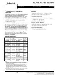
The TL-2 is a 2 channel <strong>remote</strong> <strong>control</strong> <strong>receiver</strong> supplied by 12 VDC with relay output working by radio-frequency. It will<br />
recognise the signal from TL-5 or TL-6 emitters, verify the security code and maintain the output connected until you stop<br />
to press the push button of the emitter. You could configure your own security code (between 13.122 possibilities) as well<br />
as to work with theTL-5 or the TL-6 emitters.<br />
It includes micro-switches to select the code, antenna output, led and acoustic signal for the output as well as<br />
connection terminals.<br />
Don't forget to read all the information sheet in order to obtain a perfect operating of the module.<br />
TECNICHAL CHARACTERISTICS.<br />
Voltage ................................................................................................ From 12 up to 15 VDC.<br />
Minimum Consumption ...................................................................... 15 mA.<br />
Maximum Consumption ..................................................................... 100 mA.<br />
Operating Frequency .......................................................................... 433.92 Mhz.<br />
Maximum Distance (Approx.) .............................................................. 30 Meters.<br />
Maximum Output load ....................................................................... 3 A.<br />
Sizes .................................................................................................... 99 x 64 x 30 mm.<br />
OPERATING.<br />
POWER SUPPLY. The TL-2 circuit had to be supplied with voltage from 12 up to 15 VDC.<br />
Then, we recommended you the FE-2 power supply which has been developed to perfectly answer to the circuit needs.<br />
For mobile appliance, use a 12 VDC battery.<br />
Connect the positive of the power supply to the positive terminal indicated in the wiring map, then connect also the<br />
negative of the power supply to the negative terminal indicated in the circuit. Verify that the assembly has been correctly<br />
done, before to activate the switch supplying the module. Connect other connections as it is indicated hereafter.<br />
OPERATING. Although the circuit's operating is very easy, do not forget following points.<br />
All CEBEK <strong>remote</strong> <strong>control</strong> works with a frequency adjusted at 433.92 MHz. For this reason, they include micro-switches<br />
(INT-1) allowing to configure a security code between 13.122 possibilities, for each module. Then, your module will be<br />
different from others, even if they offer same characteristics.<br />
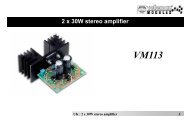
Seeing the drawing map, you could note that the micro-switches INT-1 have 8 switches with three different positions: "-",<br />
"0" and "+". You have to modify the switches position that you have received in order to select you personal code.<br />
Do not forget. The <strong>receiver</strong> and emitter have to have the same security code configured to correctly work.<br />
INT-1<br />
+<br />
0<br />
-<br />
1 2 3 4 5 6 7 8<br />
ANTENNA INSTALLATION. To obtain a maximum and clear reception, you have to install an exterior antenna. Seeing<br />
the paragraph "General Wiring map", install a metallic antenna with a length of 130 mm. The cable between antenna and<br />
module had to be shielded and inferior than 25 cm. Connect the negative terminal to the ground.<br />
OUTPUT CONFIGURATION. Even if the <strong>receiver</strong> TL-2 have been developed to <strong>control</strong> its corresponding emitter with 2<br />
channel (TL-6 module), it also could be <strong>control</strong>led by the module: 1 Channels emitter. Then, you have to select between<br />
two push buttons the wished <strong>receiver</strong> output.<br />
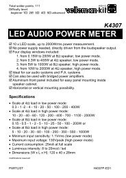
From the factory, the relay Nº1 is selected closing the jumper JP1. If you wish to <strong>control</strong> the relay Nº2 you have to get out<br />
the piece "JP" of the jumper JP1 and with is close the jumper JP2.<br />
More over, the circuit offer the possibility to activate both relays at the same time. To configure this option you have to<br />
close both jumpers JP1 and JP2.<br />
Piece<br />
JP<br />
Jumper not Closed<br />
(Open).<br />
Jumper<br />
Closed<br />
JP<br />
1
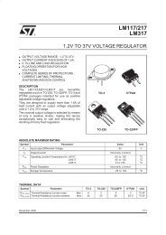
CONTROL REMOTE.<br />
GENERAL WIRING MAP.<br />
Rev. Full9809<br />
TL-2<br />
15 0<br />
TRAFO.<br />
230 0<br />
Fuse<br />
250 mA.<br />
Module<br />
FE-2<br />
Led<br />
Power Supply<br />
Ouptu 1 Output 2<br />
NO<br />
NC<br />
Common<br />
NO<br />
NC<br />
Common<br />
Relay 2<br />
Module<br />
TL-2<br />
Led 2<br />
Relay 1 Led 1<br />
JP1<br />
INT-1<br />
JP2<br />
+ 1 2 3 4 5 6 7 8<br />
0<br />
-<br />
230 V. A.C. Mains<br />
Mains Switch<br />
130 mm. Antenna.<br />
Connection to the Ground<br />
OUTPUT CONNECTION. LOAD.<br />
The output of the TL-2 module is <strong>control</strong>led by a relay, allowing any load until 3 A. as maximum consumption. The relay<br />
has 3 output terminals the normally open at quiescent (NA), the normally closed at quiescent (NC) and the common. The<br />
operating of this mechanism is the same as a switch with two (2) terminals NA and common, if you wish that the output<br />
will be activated during the timer, or between the NC and the common to obtain the reverse operating. In the drawing,<br />
you could appreciate the typical connection for a devices operating at 12 VDC and to operate at 220 VAC.<br />
12 V. D.C. TO CONNECTION<br />
(NO) Normally Open<br />
(NC) Normally Closed<br />
Common<br />
230 V. A.C. TO CONNECTION<br />
(NO) Normally Open<br />
(NC) Normally Closed<br />
Common<br />
12 V. D.C.<br />
Apparatus,<br />
load<br />
230 V. A.C.<br />
OUTPUT / DON’T FORGET. When the module is working and according to its load, it could happen an incorrect<br />
operating of the output. If it is the case, you have to install a circuit between 2 relay's contacts used for the connection.<br />
See the drawing map.<br />
Apparatus,<br />
load<br />
(NO) Normally Open<br />
(NC) Normally Closed<br />
Common<br />
100nF/400 V.<br />
Load Supply<br />
47 1/2W.<br />
Apparatus,<br />
load<br />
TECHNICAL SUPPORT AND INFORMATION.<br />
For any questions or more information:<br />
By Fax. 34.93 432.29.95<br />
By Mail: C/ Quetzal, 17-21, Entlo. 2º (08014) BARCELONA - SPAIN.<br />
By E-Mail: sat@cebek.com<br />
Keep you invoice. For any repairing could you send this with module. Else, the module will lost the warranty.<br />
All the module’s CEBEK have 3 years of total warranty in thecnical repairing,<br />
and spares from the date of buy.<br />
CEBEK is trade make of FADISEL S.L. more than 300 module’s are avaible in stock<br />
for any purpose request our CATALOGUE, or visit our Web.<br />
Http://www.cebek.com<br />
2<br />
Y<br />
EAR<br />
S