8 A DC REGULATOR 0-10V R-25 - ESR Electronic Components
8 A DC REGULATOR 0-10V R-25 - ESR Electronic Components
8 A DC REGULATOR 0-10V R-25 - ESR Electronic Components
Create successful ePaper yourself
Turn your PDF publications into a flip-book with our unique Google optimized e-Paper software.
8 A <strong>DC</strong> <strong>REGULATOR</strong> 0-<strong>10V</strong><br />
R-<strong>25</strong><br />
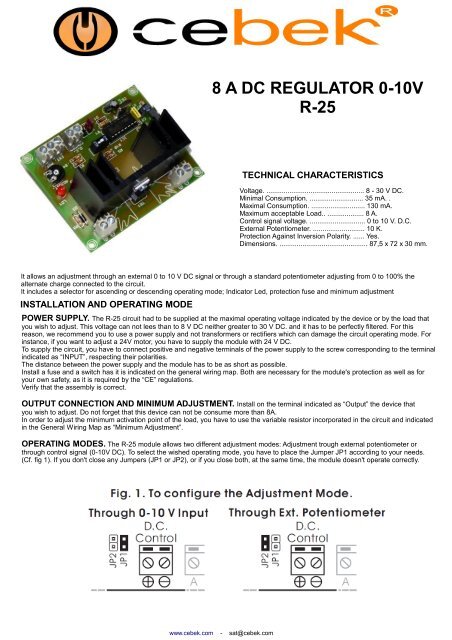
TECHNICAL CHARACTERISTICS<br />
Voltage. ................................................... 8 - 30 V <strong>DC</strong>.<br />
Minimal Consumption. ............................ 35 mA. .<br />
Maximal Consumption. ............................ 130 mA.<br />
Maximum acceptable Load.. ................... 8 A.<br />
Control signal voltage. ............................. 0 to 10 V. D.C.<br />
External Potentiometer. ........................... 10 K.<br />
Protection Against Inversion Polarity. ...... Yes.<br />
Dimensions. .............................................. 87,5 x 72 x 30 mm.<br />
It allows an adjustment through an external 0 to 10 V <strong>DC</strong> signal or through a standard potentiometer adjusting from 0 to 100% the<br />
alternate charge connected to the circuit.<br />
It includes a selector for ascending or descending operating mode; Indicator Led, protection fuse and minimum adjustment<br />
INSTALLATION AND OPERATING MODE<br />
POWER SUPPLY. The R-<strong>25</strong> circuit had to be supplied at the maximal operating voltage indicated by the device or by the load that<br />
you wish to adjust. This voltage can not lees than to 8 V <strong>DC</strong> neither greater to 30 V <strong>DC</strong>. and it has to be perfectly filtered. For this<br />
reason, we recommend you to use a power supply and not transformers or rectifiers which can damage the circuit operating mode. For<br />
instance, if you want to adjust a 24V motor, you have to supply the module with 24 V <strong>DC</strong>.<br />
To supply the circuit, you have to connect positive and negative terminals of the power supply to the screw corresponding to the terminal<br />
indicated as “INPUT”, respecting their polarities.<br />
The distance between the power supply and the module has to be as short as possible.<br />
Install a fuse and a switch has it is indicated on the general wiring map. Both are necessary for the module's protection as well as for<br />
your own safety, as it is required by the “CE” regulations.<br />
Verify that the assembly is correct.<br />
OUTPUT CONNECTION AND MINIMUM ADJUSTMENT. Install on the terminal indicated as “Output” the device that<br />
you wish to adjust. Do not forget that this device can not be consume more than 8A.<br />
In order to adjust the minimum activation point of the load, you have to use the variable resistor incorporated in the circuit and indicated<br />
in the General Wiring Map as “Minimum Adjustment”.<br />
OPERATING MODES. The R-<strong>25</strong> module allows two different adjustment modes: Adjustment trough external potentiometer or<br />
through control signal (0-<strong>10V</strong> <strong>DC</strong>). To select the wished operating mode, you have to place the Jumper JP1 according to your needs.<br />
(Cf. fig 1). If you don't close any Jumpers (JP1 or JP2), or if you close both, at the same time, the module doesn't operate correctly.<br />
www.cebek.com - sat@cebek.com
0-<strong>10V</strong> SIGNAL INPUT MODE. If you have placed the Jumper in JP1 position, the module will be configured to adjust the output<br />
according to an external input signal from 0 to 10 V <strong>DC</strong>.<br />
To inject this control signal, you have to connect positive and negative cables from the signal to the input indicated as “<strong>DC</strong> Control”,<br />
respecting their polarities. The cable length as to be as short as possible. If the distance is over to 50 cm, you have to use a shielded<br />
cable and to connect the braid to the negative screw. In all cases, the maximum length can not exceed 2 m.<br />
Once the assembly done and the module supplied, when the control signal voltage will vary the module correspondently adjust the<br />
output.<br />
The control signal has to supply a perfectly stabilised voltage and it will never overpass <strong>10V</strong>, to avoid to damage the module<br />
OPERATING MODE<br />
ADJUSTMENT MODE THROUGH EXTERNAL POTENTIOMETER. If you place the Jumper in JP2 position, the R-<strong>25</strong><br />
module will adjust the output according to the rotation of the external potentiometer connected to the circuit. The potentiometer has to be<br />
10K type and connected to the terminal indicated as “EXT. POT.”. Follow the assembly according to the instructions indicated in the<br />
“General Wiring Map” paragraph.<br />
ASCENDING / DESCENDING ADJUSTMENT. Independently of the selected operating mode, the adjustment could be done<br />
in ascending or descending mode.<br />
In the Control through Signal Input, if you place the “Config” switch on OFF position, the output will allow an adjustment between 0 and<br />
100%, directly proportional to the control signal value. At the opposite, if you place the “Config” switch on ON position, the output will<br />
operate in inverse proportion regarding to the control input. See Fig.2.<br />
To adjust through the external potentiometer, the change of the “Config” switch position will only affect the rotation way of this component<br />
R-<strong>25</strong><br />
GENERAL WIRING MAP.<br />
www.cebek.com - sat@cebek.com


