User Guide and Reference Manual - ESR Electronic Components
User Guide and Reference Manual - ESR Electronic Components
User Guide and Reference Manual - ESR Electronic Components

Create successful ePaper yourself
Turn your PDF publications into a flip-book with our unique Google optimized e-Paper software.
M2436FX<br />
<strong>User</strong> <strong>Guide</strong><br />
<strong>and</strong> <strong>Reference</strong> <strong>Manual</strong><br />
6/08<br />
6122 S. Eastern Ave<br />
Los Angeles, CA 90040<br />
www.AmericanAudio.us
M2436FX<br />
CONTENTS<br />
MAIN FEATURES....................................................................................................................................2<br />
ELECTRICAL PRECAUTIONS................................................................................................................3<br />
SAFETY PRECAUTIONS........................................................................................................................5<br />
INTRODUCTION....................................................................................................................................6<br />
SET-UP PRECAUTIONS.........................................................................................................................6<br />
Unpacking.........................................................................................................................................7<br />
quick start........................................................................................................................................7<br />
CONTROLS <strong>and</strong> FUNCTIONS<br />
CHANNEL CONTROL.................................................................................................................8<br />
MAIN CONTROL.......................................................................................................................11<br />
INPUT & OUTPUT CONNECTIONS.........................................................................................14<br />
Connectors..............................................................................................................16<br />
HOME/STUDIO RECORDING SET-UP.................................................................................................18<br />
LIVE PERFORMANCE SET UP.............................................................................................................19<br />
effects list......................................................................................................................................20<br />
CLEANING......................................................................................................................22<br />
Troubleshooting......................................................................................................................22<br />
WARRANTY.........................................................................................................................................23<br />
SPECIFICATIONS.....................................................................................................................24<br />
M2436FX<br />
Main Features<br />
• 16 Mono & 4 Stereo Channel Inputs<br />
• Stereo Main Outputs & Groups 1-2/3-4 Output<br />
• 7-B<strong>and</strong> Master EQ with On/Off Switch<br />
• Trim With Peak LED, HPF, 3-B<strong>and</strong> Sweepable, Aux 1 & 2 With Pre/Post Switch, 1 EFX, PAN,<br />
Mute, PFL & Group Switch for Mono Input<br />
• Trim With Peak LED, HPF (CH 17-20), 4-B<strong>and</strong> EQ, Aux 1 & 2 With Pre/Post Switch, 1 EFX, BAL,<br />
Mute, PFL, Group & Main L/R Switch for Stereo Input<br />
• Main L/R, Group 1-2/3-4 To Main Switch<br />
• AUX 1 & 2 Send, ON, PFL, To Group & Main Switch<br />
• HP/Control Room with Group & Main Switch<br />
• 24-Bit DSP Effect, 100 Presets, EFX On/Off & EFX Level<br />
• 10 XLR Mic/Inputs<br />
• XLR & 1/4” Phone Jack Balanced & 1/4” Phone Jack for Mono Input<br />
• XLR Balanced & 1/4” Phone Jack for Stereo (CH 17-20)<br />
• 1/4” Phone & Phono Jack For Stereo Input (Ch 21-24)<br />
• 1/4” Phone Jack For AUX Return & Phono Jack For Tape In<br />
• 1/4” Phone Jack For Main, Group, Aux, EFX, Control Room, Headphone & Footswitch<br />
• Peak for Each Mono Channel, PFL, Level Meter, Mute for Each Input., PFL for EFX, Phantom<br />
Power & DSP Program<br />
©American Audio® - www.americanaudio.us - M2436FX Instruction <strong>Manual</strong> Page 2
M2436FX<br />
ELECTRICAL SAFETY PRECAUTIONS<br />
WARNING: TO PREVENT FIRE OR ELECTRIC<br />
SHOCK HAZARD, DO NOT EXPOSE THIS<br />
UNIT TO RAIN, LIQUIDS, OR MOISTURE<br />
The serial <strong>and</strong> model number for this unit is<br />
located on the rear panel. Please write down<br />
the numbers here <strong>and</strong> retain for future reference.<br />
Model No._____________________________<br />
CAUTION: TO PREVENT ELECTRIC SHOCK<br />
DO NOT USE THIS (POLARIZED) PLUG<br />
WITH AN EXTENSION CORD, RECEPTACLE,<br />
OR OTHER TYPE OF ELECTRICAL OUTLET<br />
UNLESS THE WIDE BLADES CAN BE<br />
CAREFULLY INSERTED INTO A MATCHING<br />
WIDE SLOT.<br />
ATTENTION: POUR PREVENIR LES CHOCS<br />
ELECTRIQUES NE PAS UTILISER CETTE<br />
FICHE POLARISEE AVEC UN PROLON-<br />
GATEUR, UNE PRISE DE COURANT OU<br />
UNE AUTRE SORTIE DE COURANT, SAUF<br />
SI LES LAMES PEUVENT ETRE INSEREES A<br />
FOND SANS EN LAISSER AUCUNE PARTIE A<br />
DECOUVERT.<br />
Serial No._____________________________<br />
Purchase Notes:<br />
Date of Purchase_______________________<br />
Dealer Name__________________________<br />
Dealer Address_________________________<br />
_____________________________________<br />
_____________________________________<br />
Dealer Phone__________________________<br />
NOTE: This product satisfies FCC<br />
regulations when shielded cables<br />
<strong>and</strong> connectors are used to connect<br />
the unit to other equipment.<br />
To prevent electromagnetic interference<br />
with electrical appliances<br />
such as radios <strong>and</strong> televisions, use<br />
shielded cables <strong>and</strong> connectors<br />
for connections.<br />
©American Audio® - www.americanaudio.us - M2436FX Instruction <strong>Manual</strong> Page 3
M2436FX<br />
ELECTRICAL SAFETY PRECAUTIONS<br />
ELECTRICAL PRECAUTIONS<br />
The lightning flash with arrowhead symbol, within an<br />
equilateral triangle, is intended to alert the user to the<br />
presence of uninsulated "dangerous voltage" within the<br />
product's enclosure that may be of sufficient magnitude<br />
to constitute a risk of electric shock to persons.<br />
CAUTION<br />
RISK OF ELECTRIC SHOCK<br />
DO NOT OPEN<br />
CAUTION: TO REDUCE THE RISK OF ELECTRIC<br />
SHOCK, DO NOT REMOVE THE COVER (OR BACK).<br />
T H E R E A R E N O U S E R S E R V I C E A B L E P A R T S<br />
INSIDE REFER SERVICE TO YOUR AUTHORIZED<br />
AMERICAN AUDIO® SERVICE TECHNICIAN.<br />
The exclamation point within an equilateral triangle is<br />
intended to alert the user to the presence of important<br />
operating <strong>and</strong> maintenance (servicing) instructions in<br />
the literature accompanying the appliance.<br />
IMPORTANT SAFETY INSTRUCTIONS<br />
REad iNSTRUCTiONS — All the safety <strong>and</strong> operating<br />
instructions should be read before the product is<br />
operated.<br />
RETaiN iNSTRUCTiONS — The safety <strong>and</strong> operating<br />
instructions should be retained for future reference.<br />
HEEd WaRNiNGS — All warnings on the product <strong>and</strong><br />
in the operating instructions should be adhered to.<br />
FOLLOW iNSTRUCTiONS — All operating <strong>and</strong> use<br />
instructions should be followed.<br />
CLEaNiNG — The product should be cleaned only with<br />
a polishing cloth or a soft dry cloth. Never clean with<br />
furniture wax, benzine, insecticides or other volatile<br />
liquids since they may corrode the cabinet.<br />
aTTaCHMENTS — Do not use attachments not<br />
recommended by the product manufacturer as they<br />
may cause hazards.<br />
WaTER aNd MOiSTURE — Do not use this product<br />
near water — for example, near a bathtub, wash<br />
bowl, kitchen sink, or laundry tub; in a wet basement;<br />
or near a swimming pool; <strong>and</strong> the like.<br />
aCCESSORiES — Do not place this product on an<br />
unstable cart, st<strong>and</strong>, tripod, bracket, or table. The<br />
product may fall, causing serious injury to a child or<br />
adult, <strong>and</strong> serious damage to the product. Use only<br />
with a cart, st<strong>and</strong>, tripod, bracket, or table<br />
recommended by the manufacturer, or sold with<br />
the product. Any mounting of the product should<br />
follow the manufacturer’s instructions, <strong>and</strong> should<br />
use a mounting accessory recommended by the<br />
manufacturer.<br />
CaRT — A product <strong>and</strong> cart combination should be<br />
moved with care. Quick stops, excessive force, <strong>and</strong><br />
uneven surfaces may cause the product <strong>and</strong> cart<br />
combination to overturn.<br />
vENTiLaTiON — Slots <strong>and</strong> openings in the cabinet are<br />
provided for ventilation <strong>and</strong> to ensure reliable<br />
operation of the product <strong>and</strong> to protect it from<br />
overheating, <strong>and</strong> these openings must not be<br />
blocked or covered. The openings should never be<br />
blocked by placing the product on a bed, sofa, rug,<br />
or other similar surface. This product should not be<br />
placed in a built-in installation such as a bookcase or<br />
rack unless proper ventilation is provided or the<br />
manufacturer’s instructions have been adhered to.<br />
POWER SOURCES — This product should be operated<br />
only from the type of power source indicated on the<br />
marking label. If you are not sure of the type of<br />
power supply to your home, consult your product<br />
dealer or local power company.<br />
LOCaTiON – The appliance should be installed in a<br />
stable location.<br />
NONUSE PERiOdS – The power cord of the appliance<br />
should be unplugged from the outlet when left unused<br />
for a long period of time.<br />
GROUNdiNG OR POLaRiZaTiON<br />
• If this product is equipped with a polarized alternating<br />
current line plug (a plug having one blade wider than<br />
the other), it will fit into the outlet only one way. This<br />
is a safety feature. If you are unable to insert the plug<br />
fully into the outlet, try reversing the plug. If the plug<br />
should still fail to fit, contact your electrician to<br />
replace your obsolete outlet. Do not defeat the<br />
safety purpose of the polarized plug.<br />
• If this product is equipped with a three-wire<br />
grounding type plug, a plug having a third (grounding)<br />
pin, it will only fit into a grounding type power outlet.<br />
This is a safety feature. If you are unable to insert the<br />
plug into the outlet, contact your electrician to<br />
replace your obsolete outlet. Do not defeat the<br />
safety purpose of the grounding type plug.<br />
POWER-CORd PROTECTiON - Power-supply cords<br />
should be routed so that they are not likely to be<br />
walked on or pinched by items placed upon or<br />
against them, paying particular attention to cords at<br />
plugs, convenience receptacles, <strong>and</strong> the point where<br />
they exit from the product.<br />
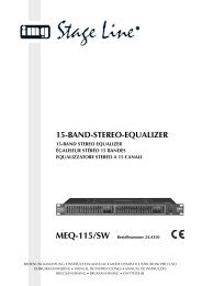
OUTdOOR aNTENNa GROUNdiNG — If an outside<br />
antenna or cable system is connected to the product,<br />
be sure the antenna or cable system is grounded so<br />
as to provide some protection against voltage surges<br />
<strong>and</strong> built-up static charges. Article 810 of the National<br />
Electrical Code, ANSI/NFPA 70, provides information<br />
with regard to proper grounding of the mast <strong>and</strong><br />
supporting structure, grounding of the lead-in wire<br />
to an antenna discharge unit, size of grounding<br />
conductors, location of antenna-discharge unit,<br />
connection to grounding electrodes, <strong>and</strong><br />
requirements for the grounding electrode. See Figure<br />
A.<br />
LiGHTNiNG — For added protection for this product<br />
during a lightning storm, or when it is left unattended<br />
<strong>and</strong> unused for long periods of time, unplug it from<br />
the wall outlet <strong>and</strong> disconnect the antenna or cable<br />
system. This will prevent damage to the product<br />
due to lightning <strong>and</strong> power-line surges.<br />
POWER LiNES — An outside antenna system should<br />
not be located in the vicinity of overhead power lines<br />
or other electric light or power circuits, or where it<br />
can fall into such power lines or circuits. When<br />
installing an outside antenna system, extreme care<br />
should be taken to keep from touching such power<br />
lines or circuits as contact with them might be fatal.<br />
OvERLOadiNG — Do not overload wall outlets,<br />
extension cords, or integral convenience receptacles<br />
as this can result in a risk of fire or electric shock.<br />
ELECTRIC<br />
SERVICE<br />
EQUIPMENT<br />
GROUND<br />
CLAMP<br />
OBJECT aNd LiQUid ENTRY - Never push objects of<br />
any kind into this product through openings as they<br />
may touch dangerous voltage points or short-out<br />
parts that could result in a fire or electric shock.<br />
Never spill liquid of any kind on the product.<br />
SERviCiNG — Do not attempt to service this product<br />
yourself as opening or removing covers may expose<br />
you to dangerous voltage or other hazards. Refer all<br />
servicing to qualified service personnel.<br />
daMaGE REQUiRiNG SERviCE - Unplug this product<br />
from the wall outlet <strong>and</strong> refer servicing to qualified<br />
service personnel under the following conditions:<br />
• When the power-supply cord or plug is damaged.<br />
• If liquid has been spilled, or objects have fallen into<br />
the product.<br />
• If the product has been exposed to rain or water.<br />
• If the product does not operate normally by following<br />
the operating instructions. Adjust only those controls<br />
that are covered by the operating instructions as an<br />
improper adjustment of other controls may result in<br />
damage <strong>and</strong> will often require extensive work by a<br />
qualified technician to restore the product to its<br />
normal operation.<br />
• If the product has been dropped or damaged in any<br />
way.<br />
• When the product exhibits a distinct change in<br />
performance — this indicates a need for service.<br />
REPLaCEMENT PaRTS -- W hen replacement parts<br />
are required, be sure the service technician has used<br />
replacement parts specified by the manufacturer or<br />
have the same characteristics as the original part.<br />
Unauthorized substitutions may result in fire, electric<br />
shock, or other hazards.<br />
SaFETY CHECk - Upon completion of any service or<br />
repairs to this product, ask the service technician to<br />
perform safety checks to determine that the product<br />
is in proper operating condition.<br />
WaLL OR CEiLiNG MOUNTiNG — The product should<br />
not be mounted to a wall or ceiling.<br />
HEaT — The product should be situated away from heat<br />
sources such as radiators, heat registers, stoves, or<br />
other products (including amplifiers) that produce<br />
heat.<br />
ANTENNA<br />
LEAD IN<br />
WIRE<br />
ANTENNA<br />
DISCHARGE UNIT<br />
(NEC SECTION 810-20)<br />
GROUNDING CONDUCTORS<br />
(NEC SECTION 810-21)<br />
GROUND CLAMPS<br />
Fig. A<br />
POWER SERVICE GROUNDING<br />
ELECTRODE SYSTEM<br />
(NEC ART 250, PART H)<br />
NEC — NATIONAL ELECTRICAL CODE<br />
©American Audio® - www.americanaudio.us - M2436FX Instruction <strong>Manual</strong> Page 4
M2436FX<br />
1. For adult use only - Keep out of the reach<br />
of children.<br />
2. Water <strong>and</strong> Moisture - The player should not<br />
be used near water - for example, near a bath<br />
tub, kitchen sink, laundry tub, in a wet basement<br />
or near a swimming pool, etc. Do not<br />
spill water or other liquids in to or on to your<br />
mixer.<br />
3. Ventilation - The Mixer should be situated<br />
so that its location or position does not interfere<br />
with its proper ventilation. For example,<br />
the Mixer should not be situated on a bed,<br />
sofa, rug, or similar surface that may block the<br />
ventilation openings; or, placed in a built-in<br />
installation, such as a bookcase or cabinet that<br />
may impede the flow of air through the ventilation<br />
openings.<br />
4. Heat - The Mixer should be situated away<br />
from heat sources such as radiators, heat registers,<br />
stoves, or other appliances (including<br />
amplifiers) that produce heat.<br />
5. Power Sources - The Mixer should be connected<br />
to a power supply (wall outlet) only of<br />
the type described in the operating instructions<br />
or as marked on the Mixer.<br />
6. Servicing -The user should not attempt to<br />
service the Mixer beyond that described in the<br />
operating instructions. There are no user serviceable<br />
parts inside. All other servicing should<br />
be referred to qualified service personnel. The<br />
Player should be serviced by qualified service<br />
personnel when:<br />
A. The power-supply cord or the plug has<br />
been damaged.<br />
B. Objects have fallen, or liquid has been<br />
spilled into the Mixer.<br />
C. The Mixer has been exposed to rain<br />
or water.<br />
D. The Mixer does not appear to operate<br />
normally or exhibits a marked change<br />
in performance.<br />
7. Never disassemble or modify your unit in<br />
any way, doing so will void your manufactures<br />
warranty.<br />
SAFETY PRECAUTIONS<br />
8. Never plug this mixer in to a dimmer pack.<br />
9. Do not let insecticides, benzene, or thinner<br />
come in contact with the surface of the<br />
unit.<br />
10. This unit is intended for indoor use only, use<br />
of this product outdoors voids all warranties.<br />
11. Always mount this unit in safe <strong>and</strong> stable<br />
matter.<br />
12. Disconnect from main power before making<br />
any type of connection.<br />
13. Cleaning - The mixer should be cleaned<br />
only as recommended by the manufacturer.<br />
Use a soft cloth to wipe down the outside of the<br />
unit. For stubborn stains moisten a soft cloth<br />
with glass cleaner or other mild detergent to<br />
wipe away any stains. Use a soft cloth to wipe<br />
any residual cleaner. Never use volatile cleaners<br />
such as benzene, solvent, or thinner to clean<br />
your unit, these cleaners will damage the units<br />
surface.<br />
14. H<strong>and</strong>le the power supply cord carefully. Do<br />
not damage or deform; it may cause electric<br />
shock or malfunction when used. Hold plug<br />
attachment when removing from wall outlet.<br />
Do not pull on the cord.<br />
15. To avoid electric shock, do not open the<br />
top cover when the unit is plugged in. If problems<br />
occur with the unit, call American Audio®<br />
customer support.<br />
16. Do not place metal objects or spill any liquids<br />
inside or on the mixer. Electric shock or<br />
malfunction may occur.<br />
17. Power Cord Protection - Power supply<br />
cords should be routed so that they are not<br />
likely to be walked on or pinched by items<br />
placed upon or against them, paying particular<br />
attention to cords at plugs, convenience receptacles,<br />
<strong>and</strong> the point where they exit from the<br />
mixer. Route your power cord out of the way of<br />
foot traffic.<br />
18. Always have the trim controls set to their<br />
lowest level during initial power-up to prevent<br />
speaker damage.<br />
©American Audio® - www.americanaudio.us - M2436FX Instruction <strong>Manual</strong> Page 5
M2436FX<br />
Introductions: Congratulations <strong>and</strong> thank you for purchasing the American Audio® M2436FX mixing<br />
board. This mixing board is a representation of American Audio’s continuing commitment to produce<br />
the best <strong>and</strong> highest quality audio products possible at an affordable price. Please read <strong>and</strong> underst<strong>and</strong><br />
this manual completely before attempting to operate your new mixer. Please carefully read <strong>and</strong><br />
underst<strong>and</strong> the instructions in this manual thoroughly before attempting to operate this unit. These<br />
instructions contain important safety information regarding the use <strong>and</strong> maintenance of this unit. Take<br />
special care to follow all warning symbols <strong>and</strong> labels both on the unit <strong>and</strong> printed in this manual. Also,<br />
Please keep this manual with the unit, for future reference.<br />
Customer Support:<br />
American Audio® provides a toll free customer support line, to provide set up help <strong>and</strong> answer any<br />
question should you encounter problems during your initial set up or operation. You may also visit us<br />
on the web at www.americanaudio.us for any comments or suggestions. Service Hours are Monday<br />
through Friday 9:00 a.m. to 5:30 p.m. Pacific St<strong>and</strong>ard Time.<br />
Voice: (800) 322-6337<br />
Fax: (323) 582-2941<br />
E-mail: support@americ<strong>and</strong>j.com<br />
To purchase parts online visit http://parts.americ<strong>and</strong>j.com<br />
Caution! There are no user serviceable parts inside this mixing board. Do not attempt any repairs<br />
yourself, without being instructed to do so by an authorized American Audio service technician. Doing<br />
so will void your manufactures warranty. In the unlikely event your mixer may require service, please<br />
contact American Audio® customer support.<br />
Do not discard the packing carton in the trash. Please recycle when ever possible.<br />
M2436FX<br />
©American Audio® - www.americanaudio.us - M2436FX Instruction <strong>Manual</strong> Page 6<br />
Introduction<br />
Set-Up Precautions<br />
Please be sure to make any connections before plugging the mixer in to an electrical outlet. All fader<br />
<strong>and</strong> volume controls should be set to zero or minimum position, before the mixer is switched on. If the<br />
mixer has been exposed to drastic temperature fluctuation (e.g. after transportation), do not switch on<br />
the mixer immediately. The arising condensation of water might damage your device. Leave the device<br />
switched off until it has reached room temperature.<br />
Operating Determinations:<br />
• When installing this mixer, please make sure that the device is not exposed or will not be<br />
exposed to extreme heat, moisture or dust!<br />
• Do not operate the mixer in extremely hot (more than 30°/100°F) or extremely cold (less than<br />
5°C/40°F) surroundings.<br />
• Keep the unit out of direct sunlight <strong>and</strong> away from heaters.<br />
• Operate the mixer only after becoming familiar with its functions. Do not permit operation by<br />
persons not qualified for operating the mixer. Most damages are the result of unprofessional<br />
operation!<br />
• Do not attempt to operate this mixer if the power cord has been frayed or damaged.<br />
• Disconnect from main power before making any type of connection.<br />
• Do not attempt to operate this mixer, if it becomes damaged in any way.<br />
• Never operate this mixer when it’s covers are removed.<br />
• To reduce the risk of electrical shock or fire, do not expose this mixer to rain or moisture.<br />
• This mixer is intended for indoor use only, use of this product outdoors voids all warranties.<br />
• During long periods of non-use, disconnect the mixer’s main power.
M2436FX<br />
Unpacking<br />
Every M2436FX has been thoroughly tested <strong>and</strong> has been shipped in perfect operating condition.<br />
Carefully check the shipping carton for damage that may have occurred during shipping. If the carton<br />
appears to be damaged, carefully inspect your mixer for any damage <strong>and</strong> be sure all equipment necessary<br />
to operate the mixer has arrived intact. In the event damage has been found or parts are missing,<br />
please contact our toll free customer support number for further instructions. Please do not return the<br />
mixer to your dealer without first contacting customer support.<br />
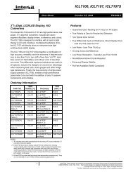
M2436FX<br />
FRONT PANEL<br />
©American Audio® - www.americanaudio.us - M2436FX Instruction <strong>Manual</strong> Page 7
M2436FX<br />
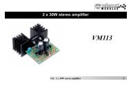
CHANNEL controls <strong>and</strong> functions<br />
CHANNEL CONTROL SECTION<br />
MONO<br />
MONO/STEREO<br />
COMBO<br />
STEREO<br />
1<br />
2<br />
3<br />
4<br />
5<br />
6<br />
7<br />
8<br />
9<br />
10<br />
11<br />
12<br />
©American Audio® - www.americanaudio.us - M2436FX Instruction <strong>Manual</strong> Page 8
M2436FX<br />
channel controls <strong>and</strong> functions cont.<br />
CHANNEL CONTROL SECTION:<br />
1. PEAK LED INDICATORs - These LED indicators will “light” when the input signal reaches 5dB<br />
below the channel’s clipping point. If the LED “lights” more then usual, you should use the TRIM CON-<br />
TROL to decrease the input level of the channel. If this does not work, reduce the output level of the<br />
connected source.<br />
2. TRIM CONTROL - This adjustment is used to adjust the audio source signal input gain for a channel.<br />
The best S/N <strong>and</strong> dynamic range balance will be reached if you adjust the TRIM CONTROL so that<br />
the PEAK INDICATORS “light” occasionally.<br />
Channel Sensitivity”<br />
MIC input sensitivity is between +6dB <strong>and</strong> -50dB.<br />
Line input sensitivity is between +14dB <strong>and</strong> -30dB.<br />
The Mono/Stereo Combo input channel sensitivity is between +20dB <strong>and</strong> -20dB.<br />
3. HPF (HIGH PASS FILTER) BUTTON - This button toggles the HPF (Hight Pass Filter) on or off. To<br />
turn the HPF on press the button in. The HPF cuts frequencies below 75Hz.<br />
4 EQUALIZER - Please see the charts below for MONO Channel <strong>and</strong> STEREO Channel EQ Type<br />
<strong>and</strong> the Max. Boost/Cut for each control. Notice the STEREO Channel has a HIGH MID <strong>and</strong> LOW<br />
MID.<br />
CHANNEL treble control - This knob is used to adjust the treble levels of the channel. Turning<br />
the knob in a counter-clockwise direction will decrease the amount of treble applied to a channel signal,<br />
turning the knob in a clockwise direction will increase the amount of treble applied to a channel signal.<br />
CHANNEL midrange control - This knob is used to adjust the midrange levels of the channel.<br />
Turning the knob in a counter-clockwise direction will CONTROL decrease MAX. the amount of midrange applied to a<br />
BOOST/CUT<br />
FREQUENCY<br />
TYPE<br />
channel signal, turning the knob in a clockwise direction will increase the amount of midrange applied<br />
HIGH ±15dB 12kHz Shelving<br />
to a channel signal.<br />
CHANNEL BASS control - This knob is used to adjust the low frequency levels of the channel.<br />
Turning the knob in a counter-clockwise direction will decrease the amount of bass applied to a<br />
LOW ±15dB 80Hz Shelving<br />
channel signal, turning the knob in a clockwise direction will increase the amount of bass applied to a<br />
channel signal.<br />
MID<br />
±15dB<br />
100HZ-8KHZ<br />
(Variable)<br />
Peaking<br />
CONTROL<br />
MONO CHANNEL<br />
MAX.<br />
BOOST/CUT<br />
FREQUENCY<br />
TYPE<br />
HIGH ±15dB 12kHz Shelving<br />
MID<br />
±15dB<br />
100HZ-8KHZ<br />
(Variable)<br />
Peaking<br />
LOW ±15dB 80Hz Shelving<br />
CONTROL<br />
STEREO CHANNEL<br />
MAX.<br />
BOOST/CUT<br />
FREQUENCY<br />
TYPE<br />
HIGH ±15dB 12kHz Shelving<br />
HIGH MID ±12dB 3kHz Peaking<br />
LOW MID ±12dB 500HZ Peaking<br />
LOW ±15dB 80HZ Shelving<br />
5. AUX 1 & AUX 2 CONTROLS - The AUX 1 knob controls the signal level that the channel sends to<br />
AUX 1 bus. The AUX 2 knob controls the signal level sent to the AUX 2 bus. If you are using the stereo<br />
channels, the signals from the L <strong>and</strong> R will be mixed <strong>and</strong> sent to the AUX 1 <strong>and</strong> AUX 2. These knobs<br />
control the AUX outputs regardless of the setting of the channel fader. See PRE/POST BUTTON concerning<br />
AUX 2. MAX.<br />
CONTROL<br />
BOOST/CUT<br />
FREQUENCY<br />
6. PRE/POST HIGH BUTTON ±15dB - This button 12kHz determines Shelvingif the AUX 2 signal is Pre Fader (signal level is not<br />
affected by fader position) or Post Fader (signnal level is affected by the fader position). This switch<br />
LOW MID ±12dB 500HZ Peaking<br />
©American Audio® - www.americanaudio.us - M2436FX Instruction <strong>Manual</strong> Page 9<br />
LOW ±15dB 80HZ Shelving<br />
TYPE<br />
HIGH MID ±12dB 3kHz Peaking
M2436FX<br />
channel controls <strong>and</strong> functions cont.<br />
applies to the AUX 2 only. The signal to AUX 1 always passes through the channel fader first.<br />
7. EFX CONTROL - These knobs control the signal levels sent to the EFX bus. The channel signals<br />
mixed by this bus have their overall level set by the MASTER EFX SEND control to the EFX jack located<br />
on the front top panel. The signal level will be affected by the channel fader’s setting.<br />
NOTE: The Effect bus signal is also fed into the internal DSP (digital signal processor).<br />
8. PAN/BALANCE CONTROL -<br />
PAN (Mono Control) - This control pans the channel signal across the master L <strong>and</strong> R buses, therefore<br />
determining the ideal position of the sound from that channel.<br />
EXAMPLE: If the PAN control is set all the way to the left, the sound from that channel will only be<br />
projected from the left speaker only. Same goes for the control being set all the way to the right, only<br />
from the right speaker.<br />
BALANCE (Stereo Control) - This control lets you adjust the balance of the L/R position, of the stereo<br />
input signal. Turning this knob to the left moves the source signal towards the MAIN MIX L bus, turning<br />
the knob to the right sends the signal towards the MAIN MIX R bus.<br />
9. MUTE BUTTON - This button when pressed “In” will cut all the signal feed going into the MAIN L/R,<br />
AUX 2 (POST), EFX buses, <strong>and</strong> GROUP FADERS 1-2 <strong>and</strong> 3-4 (faders are located on the MAIN CON-<br />
TROL SECTION). The button will glow orange when the mute function is activated.<br />
10. PFL BUTTONS - This button allows you to monitor the PRE FADER LEVEL input signal through<br />
headphones or control room outputs. When the button is NOT pressed the channel signal will be sent<br />
to the PFL bus.<br />
11. ASSIGN SWITCHES - With these buttons you can send the channel’s signal to either the GROUP<br />
1-2, GROUP 3-4, or MAIN L/R buses. Pressing the button “In” will send the signal to the corresponding<br />
bus.<br />
12. CHANNEL FADERS - Thes faders are channel’s main level control. These fader’s control the<br />
signal level sent from the channel to the master mixing, group outs, <strong>and</strong> effect buses. The settings of<br />
the input channel faders affect the mix or the sound level balance between the instruments or other<br />
sources connected to the inputs. When a channel is not being used, the fader should be set at the<br />
minimum position to prevent any unwanted noise added to the main signal.<br />
©American Audio® - www.americanaudio.us - M2436FX Instruction <strong>Manual</strong> Page 10
M2436FX<br />
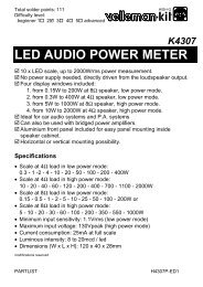
main controls <strong>and</strong> functions<br />
MAIN CONTROL SECTION<br />
13<br />
14<br />
26<br />
27<br />
15<br />
16<br />
28<br />
17<br />
18<br />
29<br />
30<br />
19<br />
20<br />
21<br />
31<br />
22<br />
23<br />
32<br />
24<br />
33<br />
25<br />
©American Audio® - www.americanaudio.us - M2436FX Instruction <strong>Manual</strong> Page 11
M2436FX<br />
main controls <strong>and</strong> functions cont.<br />
MAIN CONTROL SECTION:<br />
13. DSP PROGRAM DISPLAY - This displays shows the number of the selected effects.<br />
14. DSP PROGRAM SELECT KNOB - The program knob wil allow you to select one of the 100 built-in<br />
digital effects. This control board has a 24 Bit digital high quality effect processor. Studio effects such<br />
as Reverb, <strong>and</strong> Chorus.<br />
15. PHANTOM POWER BUTTON - When this button is pressed “In”, the mixer will supply power to<br />
all channels the provide XLR MIC input jacks. Use this function when using one or more condensor<br />
microphones.<br />
Note: When this function is active, the mixer supplies DC +48V power to pins 2 <strong>and</strong> 3 of all XLR<br />
type MIC input jacks.<br />
• Leave this switch off if you do not need phantom power.<br />
• When you turn this function on, make sure that only condenser MICs are connected to the XLR<br />
input jacks. Devices other then condensor MICs may be damaged if connected to the phantom<br />
power supply.<br />
• The switch may be left on when connecting to balanced dynamic microphones.<br />
• To avoid damage to speakers, be sure to turn off the amplifier (on powered speakers) before turning<br />
this function on or off. Also, to avoid loud noises that could cause hearing loss or device damage,<br />
we recommend that you turn all out controls (MAIN, master fader, ALT 3/4 fader etc.) to the<br />
minimum settings before activating this function.<br />
16. POWER INDICATOR - This indicator will light when mixer power switch is turned on.<br />
17. AUX PRE CONTROL - Use these knobs to adjust the signal level sent from the internal digital<br />
effect to the AUX 1 <strong>and</strong> AUX 2 buses.<br />
18. RETURN CONTROLS (AUX 1, AUX 2, AND MAIN L/R) -<br />
AUX 1 & AUX 2 CONTROL KNOBS - Use the corresponding knobs to adjust the mixed L/R signal<br />
level sent from the RETURN JACKS (L/R Mono) to the MAIN L/R bus.<br />
MAIN L/R CONTROL KNOB - Use this knob to adjust the signal level sent from the RETURN JACKS<br />
(L/R Mono) to the MAIN L/R bus.<br />
19. TAPE IN CONTROL - This knob controls the playback signal level from the component that is<br />
connected to the TAPE IN RCA JACKS located on at the top panel of the mixing board.<br />
20. TAPE IN PFL BUTTON - Pressing this button “In” will allow you to send the TAPE IN output signal<br />
to PFL bus.<br />
21. DSP ON/OFF BUTTON - This button turns the internal effect program on/off.<br />
22. PFL BUTTON - Pressing this button “In” will allow you to send the effect signal to the PFL bus.<br />
23. ASSIGN BUTTONS - Pressing these buttons will send the effect signal to the corresponding<br />
buses.<br />
24. EFX RTN FADER - Use this fader to set the signal level sent from the digital effect to the MAIN<br />
<strong>and</strong> GROUP buses.<br />
25. GROUP FADERS (1-2, 3-4) - These faders adjust the final signal level sent to the corresponding<br />
GROUP OUTPUT JACKS 1-4.<br />
26. MAIN STEREO EQUALIZER - This seven-b<strong>and</strong> MAIN STEREO EQUALIZER allows you to control<br />
©American Audio® - www.americanaudio.us - M2436FX Instruction <strong>Manual</strong> Page 12
M2436FX<br />
main controls <strong>and</strong> functions cont.<br />
the frequency response of the MAIN stereo mix bus signal. Each frequency b<strong>and</strong> has a max boost/cut<br />
of 12dB. This EQ is also very useful in cutting the frequencies that cause annoying feedback. The<br />
MAIN GRAPHIC EQ is stereo, therefore the EQ curve is applied to both the left <strong>and</strong> right signal at main<br />
output.<br />
27. MAIN EQ ON/OFF BUTTON - This function is used to activate or bypass the MAIN EQUALIZER.<br />
When the button is pressed “In”, the EQ is active, when the button is “Out”, the EQ is bypassed.<br />
28. LEVEL METER - This LED displays the signal level of the selected LEVEL METER SIGNAL BUTTON<br />
(31). When the meter lights up RED then the output is hitting the clipping level.<br />
29. MASTER SEND CONTROLS -<br />
AUX 1 & AUX 2 CONTROL KNOBS - Use the corresponding knobs to adjust the level of the signal<br />
output sent AUX 1 or AUX 2 JACKS.<br />
MASTER EFFECT CONTROLS - Use this knob to adjust the signal level of the EFFECT bus sent to the<br />
EFFECT JACK.<br />
30. CONTROL ROOM/HEADPHONE CONTROL - This controls the signal level that is sent to the<br />
CONTROL ROOM JACKS or HEADPHONE JACK.<br />
31. LEVEL-METER SIGNAL BUTTONS - Use these buttons to select the signal that is sent to either<br />
the CONTROL ROOM OUTPUTS or the HEADPHONE OUTPUT . The ouput level will be shown in the<br />
LEVEL METER.<br />
(1). If the channel’s PFL button is pressed “In”, then ONLY the channel’s PFL output is sent<br />
to either the CONTROL OUT JACKS or HEADPHONE JACK.<br />
(2). If the channel’s PFL button is “Out”, then either the MAIN L/R or GROUP 1-2/3-4, signal<br />
is sent to either the CONTROL JACKS or HEADPHONE JACK.<br />
32. TO MAIN BUTTONS - When this button is pressed “In”, the mixer will send the signal processed<br />
by the GROUP faders to the MAIN L/R bus. The GROUP 1 & 3 signal goes to MAIN L <strong>and</strong> GROUP 2<br />
& 4 signal goes to MAIN R.<br />
33. MAIN L/R FADERS - This fader adjusts the final signal level sent to the MAIN L/R OUTPUT<br />
JACKS.<br />
©American Audio® - www.americanaudio.us - M2436FX Instruction <strong>Manual</strong> Page 13
M2436FX<br />
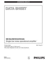
INPUT AND OUTPUT CONNECTIONS<br />
34<br />
INPUT AND OUTPUT CONNECTIONS<br />
35<br />
36 37 38<br />
39<br />
45 44 43 42 41 40<br />
INPUT AND OUTPUT CONNECTIONS:<br />
34. CHANNEL Mono INPUT JACKS -<br />
XLR JACKS - These are balanced XLR-type input jacks.<br />
BALANCED LINE IN JACKS - A st<strong>and</strong>ard 1/4” TRS phone jack is used for balanced or unbalanced<br />
line level signals. Examples of line level signals include most electronic keyboards, synthesizers,<br />
turntables (with appropriate pre-amps), tape decks <strong>and</strong> the line outputs from other mixers.<br />
35. CHANNEL stereo Input jacks - These are unbalanced stereo line input jacks. The two<br />
jacks provided are 1/4” <strong>and</strong> RCA.<br />
Note: (1). When a channel provides a 1/4” jack <strong>and</strong> an RCA jack, you may use either one of<br />
these jacks but you may not use both at the same time. Please connect to only one of<br />
these jacks on a channel.<br />
(2).The phone type jacks for CH9/10 <strong>and</strong> 11/12 also support monaural input. Specifically, if<br />
you only input into the L (MONO) jack the mixer will send the same signal through both<br />
L (MONO) <strong>and</strong> R inputs.<br />
36. TAPE INPUT JACKS - These RCA input jacks are used to connect a stereo sound source. Use<br />
these jacks when want to connect a CD or DAT directly to the mixer for monitoring. Use the TAPE<br />
IN control to adjust the signal level.<br />
©American Audio® - www.americanaudio.us - M2436FX Instruction <strong>Manual</strong> Page 14
M2436FX<br />
controls <strong>and</strong> functions cont.<br />
37. REC OUT JACKS - These jacks send the PRE FADER signal from master bus to a tape deck<br />
for recording.<br />
38. GROUP OUT (1-4) JACKS - These unbalanced 1/4” TRS phone type jacks output the GROUP<br />
1-4 signals to the input of a MTR, mixer, or other device.<br />
39. CONTROL ROOM OUTPUT JACKS - These unbalanced 1/4” TRS phone type output jacks<br />
send the mixed signal to a monitoring system. Use the CONTROL ROOM/HEADPHONE CONTROL<br />
to adjust the output signal level.<br />
NOTE: The signal monitored by these jacks is select by the using the LEVEL METER SIGNAL<br />
BUTTONS, the TAPE IN CONTROL <strong>and</strong> the PFL BUTTON on the input channels.<br />
40. HEADPHONE JACK - Use this jack to connect headphones to the mixing board.<br />
NOTE: The signal monitored by these jacks is select by the using the LEVEL METER SIGNAL<br />
BUTTONS, the TAPE IN CONTROL <strong>and</strong> the PFL BUTTON on the input channels.<br />
41. MAIN L/R OUTPUT JACKS - These unbalanced 1/4” TRS phone type jacks deliver a stereo<br />
output signal to a amplifier or powered speakers. You can also use these outputs to send a signal<br />
you wish to record. You can control the signal level control using the MAIN FADER located in the<br />
MASTER CONTROL section.<br />
42. FOOT SWITCH JACK - You can connect a foot switch to this jack, <strong>and</strong> use the foot jack to<br />
toggle the digital effects on/off.<br />
43. AUX 1, AUX 2, JACKS -<br />
AUX 1 & AUX 2 - These 1/4” output jacks send a signal from either AUX 1 or AUX 2 bus to a cue<br />
box, effector, or other monitoring system.<br />
EFX - This unbalanced phone output jack sends a signal to an external effect machine.<br />
44. STEREO RETURN L (MONO) - These are unbalanced 1/4” TRS phone-type line input jacks. The<br />
signal received by these jacks is sent to the MAIN bus <strong>and</strong> AUX1/AUX2 buses. These jacks are<br />
typically used to receive a return signal from an external effector (reverb, delay, etc.)<br />
45. CHANNEL INSERT I/O JACK - These are 1/4” TRS (tip, ring, sleeve) phone jacks that support<br />
bi-directional operation. These input/output jacks are located between the head-amplifier <strong>and</strong> the<br />
high pass filter. These jacks can be used to independently connect these channels to devices such<br />
as graphic equalizers, compressors, <strong>and</strong> noise filters.<br />
NOTE: Connection to an I/O jack requires a special separately-sold insertion cable. Please see the<br />
illustration below.<br />
INPUT/OUTPUT (I/O) JACK<br />
Tip:Output(Send to external device)<br />
Sleeve:Ground<br />
Ring:Input(Return from external device)<br />
©American Audio® - www.americanaudio.us - M2436FX Instruction <strong>Manual</strong> Page 15
M2436FX<br />
Cold (negative)<br />
Sleeve<br />
Balanced Input<br />
connectors<br />
- Always use good quality twin screened audio cable. Check for instability at the output.<br />
- Always connect both conductors at both ends, <strong>and</strong> make sure that the screen is connected only at<br />
one end.<br />
- Do not disconnect the mains earth from each piece of equipment. This is needed to provided both<br />
safety <strong>and</strong> screen returns to the system star point.<br />
- Equipment which has balanced inputs <strong>and</strong> outputs may need to be electrically isolated from the<br />
equipment rack <strong>and</strong>/or other equipment, to avoid earth loops.<br />
It is important to remember that all equipment which is connected to the mains it a potential source<br />
of hum <strong>and</strong> interference <strong>and</strong> may radiate both electrostatic or electromagnetic radiation. In addition,<br />
the mains will also act as a carrier for many forms of RF interference generated by electric motors,<br />
air-conditioning units, hyristor light dimmers etc. Unless the earth system is clean, all attempts to<br />
improve hum noise levels will be ineffective. In extreme cases there will be no alternative but to provide<br />
a completely separate <strong>and</strong> independent ‘technical earth’ to replace the incoming ‘noisy earth’.<br />
However, always consult your local electricity supply authority to ensure that safety regulations are<br />
not being infringed.<br />
American Audio products are manufactured <strong>and</strong> wired to accept wiring practices used throughout<br />
the world.<br />
Balanced XLR connections are wired as described, please see the diagram shown below:<br />
Pin #1 Shield<br />
Pin #2 Positive<br />
Pine #3 Negative<br />
Balanced 1/4” TRS connections are wired as described, please see the diagram shown below:<br />
Tip is Positive<br />
Hot (positive)<br />
2<br />
Ring is Negative<br />
Hot (positive)<br />
Cold (negative)<br />
3<br />
Sleeve is Shield<br />
Screen<br />
1<br />
Insert Points<br />
Sleeve<br />
Ring<br />
Screen<br />
Return<br />
Send<br />
Tip<br />
Sleeve<br />
Ring<br />
Tip<br />
Amp/Line Input<br />
Hot (positive)<br />
Cold (negative)<br />
Screen<br />
3 Pole (Stereo) Jack<br />
Sleeve<br />
Ring<br />
Tip<br />
Headphones<br />
Left Signal<br />
Right Signal<br />
Ground<br />
Unbalanced<br />
Input/Output<br />
AUX Send<br />
Seeve<br />
Tip<br />
Signal<br />
Ground<br />
2 Pole (Mono) Jack<br />
©American Audio® - www.americanaudio.us - M2436FX Instruction <strong>Manual</strong> Page 16
M2436FX<br />
connectors<br />
Connector <strong>and</strong> Cable Configurations<br />
REMOTE DEVICE<br />
REMOTE SIDE OF CABLE<br />
DESCRIPTION CABLE (Connector Type)<br />
2<br />
White(Red)/HIGH<br />
Black/LOW<br />
2<br />
Floating or Balanced<br />
low impedance: most<br />
professional equipment<br />
line in <strong>and</strong> line out,<br />
microphones.<br />
A. XLR**<br />
3<br />
1<br />
T R S<br />
Shield/GND<br />
White(Red)/HIGH Black/LOW<br />
1<br />
2<br />
3<br />
(XLR)<br />
B. TRS PHONE<br />
Shield/GND<br />
1<br />
3<br />
(XLR)<br />
Unbalanced<br />
low impedance: some<br />
professional equipment<br />
<strong>and</strong> microphones.<br />
C. STANDARD<br />
PHONE<br />
T<br />
S<br />
White(Red)/HIGH<br />
Shield/GND<br />
Black/LOW<br />
2<br />
1<br />
3<br />
(XLR)<br />
Unbalanced<br />
high impedance: most<br />
hi-fi equipment.<br />
D. STANDARD<br />
PHONE<br />
T<br />
S<br />
White(Red)/HIGH<br />
Shield/GND<br />
Black/LOW<br />
2<br />
1<br />
3<br />
(XLR)<br />
White(Black)/HIGH<br />
Unbalanced<br />
high impedance: most<br />
hi-fi equipment.<br />
E. SHIELD/GND<br />
PHONE<br />
T<br />
S<br />
Shield/GND<br />
S<br />
T<br />
(St<strong>and</strong>ard Phone)<br />
Connector <strong>and</strong> cable configurations are recommended for use with the M 4 bus series. These cables<br />
are based on the use of auxillary equipment that is isolated from the AC power mains.<br />
©American Audio® - www.americanaudio.us - M2436FX Instruction <strong>Manual</strong> Page 17
OUT IN<br />
PROGRAM<br />
POWER<br />
COMPACT DISC PLAYER<br />
PROGRAM<br />
POWER<br />
COMPACT DISC PLAYER<br />
STOP<br />
PLAY/PAUSE<br />
REPEAT REW SKIP FWD<br />
MIN<br />
LEVEL<br />
EJECT<br />
MAX<br />
STOP<br />
PLAY/PAUSE<br />
REPEAT REW SKIP FWD<br />
MIN<br />
LEVEL<br />
EJECT<br />
MAX<br />
M2436FX<br />
home studio Set-Up<br />
Setup Procedure:<br />
1. Before connecting to microphones <strong>and</strong> instruments, be sure that all devices are turned off. Also<br />
be sure that all of the mixer’s channel fader <strong>and</strong> master control faders are set all the way down.<br />
2. For each connection, connect one end of the cable to the relevant microphone or instrument <strong>and</strong><br />
connect the other end to the appropriate input jack on the mixer.<br />
NOTE: Where an input channel provides both a MIC INPUT jack <strong>and</strong> a LINE INPUT jack, you<br />
may use either one of these jack but you may not use both at the same time. Please<br />
connect to only one of these jacks on each channel.<br />
3. To avoid causing damage to speaker, power up the devices in the following order: Peripheral<br />
devices mixer power amps (or powered speakers).<br />
NOTE: When shutting the system down, turn off the power in the opposite order: Power amps<br />
(powered speakers) mixer Peripheral devices.<br />
Master Recorder(MD,DAT.)<br />
Sound Source(CD,MD,DAT,<br />
Cassette,Video etc.)<br />
Microphone<br />
Foot Switch<br />
1<br />
MIC<br />
2<br />
MIC<br />
3<br />
MIC<br />
4<br />
MIC<br />
5<br />
MIC<br />
6<br />
MIC<br />
7<br />
MIC<br />
8<br />
MIC<br />
9/10<br />
MIC<br />
11/12<br />
MIC<br />
13/14<br />
LINE 13<br />
15/16<br />
LINE 15<br />
TAPE IN<br />
REC OUT<br />
GROUP OUTPUT<br />
CONTROL ROOM<br />
LINE 14<br />
LINE 16<br />
LINE<br />
LINE<br />
LINE<br />
LINE<br />
LINE<br />
LINE<br />
LINE<br />
LINE<br />
LINE 9<br />
LINE 11<br />
LINE 13<br />
LINE 15<br />
AUX RETURN<br />
AUX 1 SEND<br />
FOOT SWITCH<br />
MAIN OUTPUT<br />
MONO<br />
MONO<br />
HEADPHONE<br />
INSERT<br />
INSERT<br />
INSERT<br />
INSERT<br />
INSERT<br />
INSERT<br />
INSERT<br />
INSERT<br />
LINE 10<br />
LINE 12<br />
LINE 14<br />
LINE 16<br />
MONO<br />
AUX 2 SEND<br />
EFX SEND<br />
Effector<br />
Rhythm Machine<br />
Effector<br />
Effector<br />
Synthesizer<br />
MTR<br />
Guitar<br />
Powered Monitor<br />
Speakers<br />
©American Audio® - www.americanaudio.us - M2436FX Instruction <strong>Manual</strong> Page 18
M2436FX<br />
Live Performance Set-Up<br />
Monitor Speakers<br />
(Internal)<br />
Guitar<br />
CD,Cassette,or<br />
DAT Recorder<br />
Power Amp<br />
Microphone<br />
Microphone<br />
CD Player<br />
1<br />
MIC<br />
2<br />
MIC<br />
3<br />
MIC<br />
4<br />
MIC<br />
5<br />
MIC<br />
6<br />
MIC<br />
7<br />
MIC<br />
8<br />
MIC<br />
9/10<br />
MIC<br />
11/12<br />
MIC<br />
13/14<br />
LINE 13<br />
15/16<br />
LINE 15<br />
TAPE IN<br />
REC OUT<br />
GROUP OUTPUT<br />
CONTROL ROOM<br />
LINE 14<br />
LINE 16<br />
LINE<br />
LINE<br />
LINE<br />
LINE<br />
LINE<br />
LINE<br />
LINE<br />
LINE<br />
LINE 9<br />
LINE 11<br />
LINE 13<br />
LINE 15<br />
AUX RETURN<br />
AUX 1 SEND<br />
FOOT SWITCH<br />
MAIN OUTPUT<br />
MONO<br />
MONO<br />
HEADPHONE<br />
INSERT<br />
INSERT<br />
INSERT<br />
INSERT<br />
INSERT<br />
INSERT<br />
INSERT<br />
INSERT<br />
LINE 10<br />
LINE 12<br />
LINE 14<br />
LINE 16<br />
MONO<br />
AUX 2 SEND<br />
EFX SEND<br />
OUT IN<br />
DI<br />
Synthesizer<br />
Foot Switch<br />
Power Amp<br />
Bass<br />
Guitar<br />
Stage (Internal)<br />
Effector<br />
ST<br />
AUX<br />
(PRE )<br />
Audience(External)<br />
ST<br />
Main Speakers<br />
(External)<br />
©American Audio® - www.americanaudio.us - M2436FX Instruction <strong>Manual</strong> Page 19
M2436FX<br />
Effects List<br />
Program<br />
Room<br />
Effect Name Effect Description Efx Level<br />
No.(Hex)<br />
Size<br />
00h Medium Bright Plate<br />
78.00% 8.00mc<br />
01h Best Plate<br />
63.00% 36.78mc<br />
02h Medium Dark Spring<br />
13.00% 9.00mc<br />
03h Short Plate<br />
78.00% 8.00mc<br />
04h Long Bright Spring<br />
13.00% 9.00mc<br />
Performance<br />
05h Slapback 2<br />
100.00% 8.00mc<br />
06h Slapback w verb<br />
91.00% 8.00mc<br />
07h Echo-Verb echo long verb 28.00% 30.61mc<br />
08h Slow st chor<br />
100.00% 12.11mc<br />
09h Hall best hall 2<br />
78.00% 35.75mc<br />
10h Short Hall<br />
44.00% 8.00mc<br />
11h Short Dark Hall<br />
35.00% 9.00mc<br />
12h Short Bright Hall<br />
35.00% 8.00mc<br />
13h Medium Hall<br />
27.00% 9.00mc<br />
14h Medium Dark Hall<br />
21.00% 8.00mc<br />
Hall<br />
15h Medium Bright Hall<br />
27.00% 9.00mc<br />
16h Long Hall<br />
13.00% 9.00mc<br />
17h Long Dark Hall<br />
21.00% 9.00mc<br />
18h Long Brigh Hall<br />
27.00% 9.00mc<br />
19h Best Hall<br />
58.00% 9.00mc<br />
20h Short Plate<br />
78.00% 8.00mc<br />
21h Short Dark Plate<br />
78.00% 8.00mc<br />
22h Short Bright Plate<br />
78.00% 8.00mc<br />
23h Long Bright Plate<br />
26.00% 45.00mc<br />
24h Medium Dark Plate<br />
78.00% 45.00mc<br />
Plate<br />
25h Medium Bright Plate<br />
78.00% 8.00mc<br />
26h Medium Plate<br />
78.00% 8.00mc<br />
27h Long Plate<br />
78.00% 45.00mc<br />
28h Long Dark Plate<br />
52.00% 45.00mc<br />
29h Best Plate<br />
63.00% 36.78mc<br />
30h Short Spring<br />
13.00% 9.00mc<br />
31h Short Dark Spring<br />
13.00% 8.00mc<br />
32h Short Bright Spring<br />
13.00% 8.00mc<br />
33h Medium Spring<br />
13.00% 9.00mc<br />
34h Medium Dark Spring<br />
13.00% 9.00mc<br />
Spring<br />
35h Medium Bright Spring<br />
13.00% 9.00mc<br />
36h Long Spring<br />
13.00% 9.00mc<br />
37h Long Dark Spring<br />
13.00% 9.00mc<br />
38h Long Bright Spring<br />
13.00% 9.00mc<br />
39h Best Spring<br />
13.00% 9.00mc<br />
40h Slapback 2<br />
100.00% 8.00mc<br />
41h Short Echo<br />
80.00% 8.00mc<br />
42h 420ms Delay High Feedback 100.00% 8.00mc<br />
43h 420ms Delay Low Feedback 100.00% 8.00mc<br />
44h Echo 550-275ms Delay cross Feedback 100.00% 8.00mc<br />
45h 550ms Delay High Feedback 100.00% 8.00mc<br />
46h 550ms Delay Low Feedback 100.00% 8.00mc<br />
47h 650-375ms Delay cross Feedback 100.00% 8.00mc<br />
48h 650ms Delay High Feedback 100.00% 8.00mc<br />
50h ©American Audio® - www.americanaudio.us Flanger - M2436FX Reverb Instruction <strong>Manual</strong> Page 100.00% 20 34.72mc<br />
51h Flanger Short reverb 100.00% 34.72mc<br />
52h It Flanger Medium Reverb 99.00% 29.58mc
M2436FX<br />
44h Echo 550-275ms Delay cross Feedback 100.00% 8.00mc<br />
45h 550ms Delay High Feedback 100.00% 8.00mc<br />
46h 550ms Delay Low Feedback 100.00% 8.00mc<br />
47h 650-375ms Delay cross Feedback 100.00% 8.00mc<br />
48h 650ms Delay High Feedback 100.00% 8.00mc<br />
50h Flanger Reverb<br />
100.00% 34.72mc<br />
51h Flanger Short reverb 100.00% 34.72mc<br />
52h It Flanger Medium Reverb 99.00% 29.58mc<br />
53h Medium Flanger Medium Reverb 100.00% 18.28mc<br />
54h Slow Flanger Long Reverb 100.00% 29.58mc<br />
Flanger+Verb<br />
55h Flanger Long Reverb 100.00% 29.58mc<br />
56h Stereo Flanger Medium Reverb 100.00% 29.58mc<br />
57h Stereo Flanger Long Reverb 100.00% 29.58mc<br />
58h Whip Flanger Short Reverb 100.00% 21.36mc<br />
59h Whip Flanger Long Reverb 100.00% 29.58mc<br />
60h Slow Chorus Short Reverb 100.00% 30.61mc<br />
61h Slow Chorus Medium Reverb 100.00% 36.78mc<br />
62h Slow Chorus Long Reverb 100.00% 36.78mc<br />
63h Medium Chorus Medium Reverb 79.00% 29.58mc<br />
64h Medium Chorus Long Reverb 79.00% 29.58mc<br />
Chorus+Verb<br />
65h Fast Chorus Short Reverb 100.00% 30.61mc<br />
66h Fast Chorus Long Reverb 100.00% 29.58mc<br />
67h Trem Chorus Medium Reverb 100.00% 31.64mc<br />
68h Trem Chorus Long Reverb 100.00% 36.78mc<br />
69h Big Chorus Medium Reverb 100.00% 29.58mc<br />
70h Echo-Verb 1<br />
33.00% 17.25mc<br />
71h Hard echo Medium verb 32.00% 26.50mc<br />
72h Echo-Verb 2<br />
53.00% 40.89mc<br />
73h Echo-Verb 4<br />
37.00% 28.56mc<br />
74h Echo-Verb 3<br />
23.00% 45.00mc<br />
Echo+Verb<br />
75h Pre delay serial<br />
48.00% 29.58mc<br />
76h Cross echo<br />
72.00% 8.00mc<br />
77h Echo long verb<br />
28.00% 30.61mc<br />
78h Echo cross verb<br />
29.00% 30.61mc<br />
79h Echoverb<br />
18.00% 37.81mc<br />
80h Chorus 1<br />
100.00% 8.00mc<br />
81h Chorus 2<br />
100.00% 11.08mc<br />
82h Chorus fast<br />
100.00% 8.00mc<br />
83h Deep slow chorus<br />
100.00% 8.00mc<br />
84h Deep fast chorus<br />
72.00% 8.00mc<br />
Chorus<br />
85h Medium slow chorus 100.00% 8.00mc<br />
86h Slow stereo chorus<br />
100.00% 8.00mc<br />
87h Leslie<br />
100.00% 8.00mc<br />
88h Medium leslie<br />
100.00% 8.00mc<br />
89h Stereo chorus<br />
100.00% 8.00mc<br />
90h Slow It Flange<br />
100.00% 41.92mc<br />
91h It Flanger<br />
100.00% 8.00mc<br />
92h Deep slow flanger<br />
100.00% 41.92mc<br />
93h Deep It flanger<br />
100.00% 41.92mc<br />
94h Deep lazer flanger<br />
100.00% 41.92mc<br />
Flanger<br />
95h Jet flanger 1<br />
100.00% 41.92mc<br />
96h Jet flanger 2<br />
100.00% 41.92mc<br />
97h Medium flanger<br />
100.00% 8.00mc<br />
98h Medium lazer flanger 100.00% 41.92mc<br />
99h Strong flanger<br />
100.00% 41.92mc<br />
Effects List Cont.<br />
©American Audio® - www.americanaudio.us - M2436FX Instruction <strong>Manual</strong> Page 21
M2436FX<br />
Dust will settle in the fader track overtime dust can cause a popping noise on the fader. To prevent<br />
this cover you mixer. If the mixer has been unused for over a month or more move you faders up <strong>and</strong><br />
down a couple of times this will move most of the settle dust from the fader track. Do not eat, drink,<br />
or smoke over you over or near the mixer.<br />
Don’t use spray cleaners. Use compressed air or a vacuum with a brush accessory.<br />
Cleaning frequency depends on the environment in which the mixer operates (i.e. smoke, fog residue,<br />
dust, dew).<br />
M2436FX<br />
Cleaning<br />
TROUBLESHOOTING<br />
Trouble Shooting: Listed below are common problems you may encounter, <strong>and</strong> solutions.<br />
I can’t hear the source from a channel thru the main mix<br />
Check the trim knob, fader, <strong>and</strong> output volume on your source.<br />
Check the Mute button, or make sure your sub groups are assigned to the mains.<br />
Check you connection from the source to the mixer.<br />
Try the same connection on a different channel with the same settings.<br />
I hear noise in mix<br />
Check your power a 60Hz hum, could come from ungrounded equipment.<br />
Turn all the faders down one at a time <strong>and</strong> the stereo return knob. If the noise goes away<br />
it’s that channel or the source. Disconnect the source from the mixer bring up that fader if<br />
the noise is gone it your source, If it is the source try bringing down its out put volume.<br />
I have no power<br />
Make sure your power supply is properly hooked up to the unit.<br />
I can’t hear the mix on my headphones or my control room monitors<br />
Check the phones / control room knob, Select the proper source.<br />
©American Audio® - www.americanaudio.us - M2436FX Instruction <strong>Manual</strong> Page 22
M2436FX<br />
The M2436FX carries a one year limited warranty. We recommend you fill out the enclosed warranty<br />
card to validate your purchase. All returned service items whether under warranty or not, must be freight<br />
pre-paid <strong>and</strong> accompany a R.A. (return authorization) number. If the mixer is under warranty, you must<br />
provide a proof of purchase invoice. You may obtain a R.A. number by contacting our customer support<br />
team on our toll free number. Please contact American Audio® customer support at (800) 322-6337<br />
for a R.A. number. All package not displaying a R.A. number on the outside of the package will<br />
be returned to the shipper.<br />
1-YEAR LIMITED WARRANTY<br />
A. American Audio® hereby warrants, to the original purchaser, American Audio® products to be free<br />
of manufacturing defects in material <strong>and</strong> workmanship for a period of 1 Year (365 days) from the date<br />
of purchase. This warranty shall be valid only if the product is purchased within the United States of<br />
America, including possessions <strong>and</strong> territories. It is the owner’s responsibility to establish the date <strong>and</strong><br />
place of purchase by acceptable evidence, at the time service is sought.<br />
B. For warranty service, send the product only to the American Audio® factory. All shipping charges<br />
must be pre-paid. If the requested repairs or service (including parts replacement) are within the terms<br />
of this warranty, American Audio® will pay return shipping charges only to a designated point within<br />
the United States. If the entire instrument is sent, it must be shipped in its original package. No accessories<br />
should be shipped with the product. If any accessories are shipped with the product, American<br />
Audio® shall have no liability whatsoever for loss of or damage to any such accessories, nor for the<br />
safe return thereof.<br />
C. This warranty is void if the serial number has been altered or removed; if the product is modified in<br />
any manner which American Audio® concludes, after inspection, affects the reliability of the product;<br />
if the product has been repaired or serviced by anyone other than the American Audio® factory unless<br />
prior written authorization was issued to purchaser by American Audio®; if the product is damaged<br />
because not properly maintained as set forth in the instruction manual.<br />
D. This is not a service contract, <strong>and</strong> this warranty does not include maintenance, cleaning or periodic<br />
check-up. During the period specified above, American Audio® will replace defective parts at<br />
its expense, <strong>and</strong> will absorb all expenses for warranty service <strong>and</strong> repair labor by reason of defects<br />
in material or workmanship. The sole responsibility of American Audio® under this warranty shall be<br />
limited to the repair of the product, or replacement thereof, including parts, at the sole discretion of<br />
American Audio®. All products covered by this warranty were manufactured after January 1, 1990, <strong>and</strong><br />
bear identifying marks to that effect.<br />
E. American Audio® reserves the right to make changes in design <strong>and</strong>/or improvements upon its products<br />
without any obligation to include these changes in any products theretofore manufactured.<br />
F. No warranty, whether expressed or implied, is given or made with respect to any accessory supplied<br />
with products described above. Except to the extent prohibited by applicable law, all implied<br />
warranties made by American Audio® in connection with this product, including warranties of merchantability<br />
or fitness, are limited in duration to the warranty period set forth above. And no warranties,<br />
whether expressed or implied, including warranties of merchantability or fitness, shall apply to<br />
this product after said period has expired. The consumer’s <strong>and</strong> or Dealer’s sole remedy shall be such<br />
repair or replacement as is expressly provided above; <strong>and</strong> under no circumstances shall American<br />
Audio® be liable for any loss or damage, direct or consequential, arising out of the use of, or inability<br />
to use, this product.<br />
G. This warranty is the only written warranty applicable to American Audio® Products <strong>and</strong> supersedes<br />
all prior warranties <strong>and</strong> written descriptions of warranty terms <strong>and</strong> conditions heretofore published.<br />
©American Audio® - www.americanaudio.us - M2436FX Instruction <strong>Manual</strong> Page 23<br />
Warranty
M2436FX<br />
Model: M2436FX<br />
Power supply:<br />
Dimensions:<br />
Weight:<br />
Power Consumption:<br />
Operating Temperature:<br />
Specifications<br />
AC 115v~60Hz/230v~50Hz<br />
Single Voltage:<br />
AC 100V, 50/60Hz (Japan);<br />
AC 110V, 60Hz (Colombia)<br />
AC 120V, 60Hz (U.S.A. <strong>and</strong> Canada); AC 127V, 60Hz (Mexico)<br />
AC 220V, 50Hz (Chile <strong>and</strong> Argentina); AC 240V, 50Hz (Australia)<br />
AC 220V, 60Hz (Philippines <strong>and</strong> Korea)<br />
AC 230V, 50Hz (Europe, U.K., New Zeal<strong>and</strong>, South Africa, <strong>and</strong> Singapore)<br />
652mm (W) x 420mm (D) x 90mm (H)<br />
25.6” (W) x 16.5” (D) x 3.54” (H)<br />
16.7 Lbs. / 7.6 Kgs.<br />
55W<br />
5 to 35 deg. C; Humidity: 25 to 85% RH<br />
(non-condensing); Storage Temperature: -20 to 60 deg. C<br />
MAXIMUM OUTPUT LEVEL (0.5% T.H.D. AT 1kHz):<br />
FREQUENCY RESPONSE:<br />
+26dB (Main L/R) @ 10Ω, +20dB (Group 1-2/3-4, Aux 1 & 2/EFX,<br />
& Control Room) @ 10Ω, +20dB (Insert) @ 10Ω, More than<br />
100mW (Headphones) @ 33Ω<br />
20Hz ~ 20kHz, +1/-2dB (Mix L/R, Group 1-2/3-4, Aux 1 & 2/EFX<br />
Send, & Control Room) @ 10Ω<br />
T.H.D. (Total Harmonic Distortion):
M2436FX<br />
CHANNEL INDICATORS:<br />
PEAK: An indicator for each channel turns on when the pre-channel fader signal is 5dB below clipping.<br />
Specifications<br />
INTERNAL DIGITAL EFFECT:<br />
LED METERS:<br />
MONO INPUT CHANNEL EQ:<br />
HIGH:<br />
MID:<br />
LOW:<br />
TURNOVER/ROLL OFF FREQUENCIES:<br />
STEREO INPUT CHANNEL EQ:<br />
HIGH:<br />
MID:<br />
LOW MID:<br />
LOW:<br />
TURNOVER/ROLL OFF FREQUENCIES:<br />
100 Selectable Presets/Foot Switch Controlable<br />
10-Segment LEDx2, Main L/R, GROUP 1-2/3-4, PFL (selectable)<br />
12kHz Shelving<br />
100-8kHz Peeking<br />
80Hz Shelving<br />
Located 3dB Below Maximum Boost/Cut<br />
12kHz Shelving<br />
3kHz Peeking<br />
500Hz Peaking<br />
80Hz Shelving<br />
Located 3dB Below Maximum Boost/Cut<br />
GAIN CONTROL (MONO/STEREO COMBINATION INPUT CHANNEL):<br />
40dB Variable (-20db ~ +20dB)<br />
GAIN CONTROL (MONO INPUT CHANNEL):<br />
GRAPHIC EQUALIZER:<br />
PHANTOM POWER (BALANCED INPUT):<br />
CROSSTALK (at 1kHz):<br />
44dB Variable (-50dB ~ +6dB), (-30dB ~ +14dB)<br />
7-B<strong>and</strong> (63, 160, 400, 1K, 2.5K, 6.4K, 16kHz)<br />
+48V DC<br />
-70dB Between Input Channels,<br />
-70dB Between Input/Output Channels<br />
©American Audio® - www.americanaudio.us - M2436FX Instruction <strong>Manual</strong> Page 25
©American Audio® World Headquarters:<br />
6122 S. Eastern Ave. Los Angeles, CA 90040 USA<br />
Tel: 323-582-3322 Fax: 323-582-2941<br />
Web: www.americanaudio.us E-mail: info@americ<strong>and</strong>j.com<br />
American DJ Europe<br />
Junostraat 2<br />
6468 EW Kerkrade<br />
Netherl<strong>and</strong>s<br />
service@americ<strong>and</strong>jeurope.com / www.americ<strong>and</strong>jeurope.com<br />
Tel: +31 45 546 85 00 / Fax: +31 45 546 85 99