Rexnord® and Link-Belt® Roller Chains I Catalog - Acorn Bearings
Rexnord® and Link-Belt® Roller Chains I Catalog - Acorn Bearings
Rexnord® and Link-Belt® Roller Chains I Catalog - Acorn Bearings

Create successful ePaper yourself
Turn your PDF publications into a flip-book with our unique Google optimized e-Paper software.
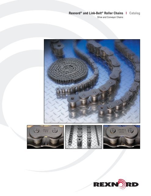
Rexnord ® <strong>and</strong> <strong>Link</strong>-Belt ® <strong>Roller</strong> <strong>Chains</strong> I <strong>Catalog</strong><br />
Drive <strong>and</strong> Conveyor <strong>Chains</strong>
Contents<br />
Introduction Introduction A-1<br />
A<br />
Drive <strong>Chains</strong><br />
St<strong>and</strong>ard <strong>Roller</strong> <strong>Chains</strong> B-1, SU <strong>and</strong> H Series<br />
<strong>Chains</strong> B-4, Double Pitch Drive <strong>Chains</strong> B-6, Extra<br />
Clearance <strong>Chains</strong> B-6, Corrosion Resistant <strong>Chains</strong><br />
B-7, O-Ring <strong>Chains</strong> B-8.<br />
B<br />
Drive Engineering<br />
Engineering Recommendations C-1,<br />
Specifications, Dimensions <strong>and</strong> Ratings C-9,<br />
Lubrication C-45, Drive Installation C-47.<br />
C<br />
Conveyor <strong>Chains</strong><br />
Introduction D-1, St<strong>and</strong>ard <strong>Roller</strong> <strong>Chains</strong> <strong>and</strong><br />
Attachments D-2, Double Pitch <strong>Roller</strong> <strong>Chains</strong> <strong>and</strong><br />
Attachments D-4, Redi-Lube Chain D-8, Hollow Pin<br />
Chain D-10, Side Bow Chain D-14, Block Chain<br />
D-15<br />
D<br />
Conveyor Engineering<br />
Engineering Recommendations E-1, Selection<br />
Procedure E-4, Layouts <strong>and</strong> Formulas E-6,<br />
Selection Example E-8, Lubrication E-9, Sprocket<br />
Data E-10.<br />
E<br />
British St<strong>and</strong>ard<br />
St<strong>and</strong>ard <strong>Roller</strong> Chain F-1, RC with Straight<br />
<strong>Link</strong> Plates F-4, RC for Heavy Drives <strong>and</strong> Lifting<br />
Applications F-4, RC with Thermoplastic <strong>Bearings</strong><br />
F-5, Hollow Pin F-6, Side Bow F-7, Double Pitch<br />
<strong>Roller</strong> Chain F-8.<br />
F<br />
Other Products <strong>and</strong><br />
Information<br />
Specifications G-1, Sprocket Reference Data<br />
G-2, Chain <strong>and</strong> Parts Packaging G-3, Chain Parts<br />
St<strong>and</strong>ards G-4, Chain Repair Tools G-5.<br />
G<br />
Technical Data<br />
Technical Data H-1, Chain Index H-3.<br />
H
<strong>Link</strong>-Belt ® <strong>and</strong> Rexnord ® <strong>Roller</strong> Chain<br />
The best. By choice.<br />
A<br />
Many diverse elements go into each<br />
link of roller chain. Engineering<br />
ability. Material quality. Manufacturing<br />
technologies. Worker skills. And, every<br />
chain manufacturer has the same<br />
opportunity to select the elements<br />
which constitute this product.<br />
Rexnord has chosen to produce only<br />
the best.<br />
Doing that requires the highest quality<br />
materials, designed <strong>and</strong> improved<br />
by the best engineering minds, <strong>and</strong><br />
manufactured by the industry’s most<br />
advanced <strong>and</strong> precise processes.<br />
It requires never st<strong>and</strong>ing still, but<br />
constantly striving to improve ... <strong>and</strong><br />
backing that effort with the financial<br />
commitment a continuing investment in<br />
quality requires.<br />
It requires insisting on tough internal<br />
quality st<strong>and</strong>ards that exceed even the<br />
dem<strong>and</strong>ing minimums required by the<br />
American National St<strong>and</strong>ards Institute.<br />
It requires staying constantly in touch<br />
with individual needs for roller chain<br />
that will deliver long life <strong>and</strong> reliable<br />
performance, even in the most limited<br />
space <strong>and</strong> under the harshest of<br />
hostile environments.<br />
And it requires building on more than a<br />
century of experience <strong>and</strong> tradition, to<br />
provide products which deliver an extra<br />
edge in performance. Time after time<br />
after time.<br />
All of these factors add up to your<br />
assurance that only the highest quality<br />
roller chain bears the familiar <strong>Link</strong>-Belt ®<br />
<strong>and</strong> Rexnord ® symbol on its sidebars.<br />
It’s the best by choice.<br />
Superior quality<br />
support for superior<br />
quality products<br />
No matter how good it is, any roller<br />
chain falls short of being the best if<br />
it isn’t available when <strong>and</strong> where it’s<br />
needed.<br />
So a wide network of stock-carrying<br />
distributors maintain immediately<br />
available quantities of <strong>Link</strong>-Belt ® <strong>and</strong><br />
Rexnord ® roller chain. To give you the<br />
best, when <strong>and</strong> where you need it.<br />
In turn, vast <strong>Link</strong>-Belt ® <strong>and</strong> Rexnord ®<br />
warehouse inventories support<br />
distributor stocks, allowing for overnight<br />
delivery in many cases.<br />
Further supplementing these efforts,<br />
strategically located Sales Offices <strong>and</strong><br />
Service Centers provide for direct,<br />
in-depth consultation. Each is staffed<br />
with knowledgeable customer service<br />
representatives <strong>and</strong> sales specialists,<br />
who are able to aid in matters from<br />
the simplest application questions to<br />
developing complete power transmission<br />
systems for specific applications.<br />
11<br />
A-1
<strong>Link</strong>-Belt ® <strong>and</strong> Rexnord ® <strong>Roller</strong> Chain Features <strong>and</strong> Benefits<br />
A<br />
Features<br />
Benefits<br />
<strong>Link</strong>-Belt ® Rexnord ® <strong>Link</strong>-Belt ® Rexnord ®<br />
Holes quality is critical to maintaining the overall fatigue<br />
strength of the chain.<br />
Precision pierced holes<br />
This results in higher pin <strong>and</strong> bushing push outs <strong>and</strong><br />
improves fatigue strength.<br />
Extends chain life.<br />
Precision-controlled heat treatment process<br />
Critical for performance both in wear conditions <strong>and</strong><br />
fatigue life.<br />
Consistent, high quality.<br />
Automatically assembled & preloaded<br />
Ensures precision components, tight tolerances, <strong>and</strong><br />
uniformity.<br />
Easy installation <strong>and</strong> alignment.<br />
Pre-lubricant is the most important lubrication a chain<br />
undergoes. All chains are hot dipped in a special chain<br />
lubricant that penetrates chain joints.<br />
Factory pre-lubrication<br />
Provides for minimal lubrication required at installation.<br />
Improves chain life in use or on the shelf.<br />
Through-hardened pins<br />
(from 80 pitch <strong>and</strong> upward)<br />
Case-hardened pins<br />
Provides maximum<br />
strength.<br />
Maximum wear life.<br />
Shot-peened components &<br />
Drifted sidebars (ONLY for<br />
API Certified <strong>Chains</strong>.)<br />
Improves overall fatigue<br />
strength.<br />
Increased chain life.<br />
A-2
<strong>Link</strong>-Belt ® <strong>and</strong> Rexnord ® <strong>Roller</strong> <strong>Chains</strong><br />
Drives<br />
St<strong>and</strong>ard roller chain is broadly used in<br />
power transmission applications ranging<br />
from general industrial applications to<br />
dem<strong>and</strong>ing oil field service to operation<br />
in such specialized areas as food<br />
processing <strong>and</strong> heavy construction<br />
equipment.<br />
Single <strong>and</strong> multiple st<strong>and</strong>ard roller<br />
chains, available in many sizes, meet<br />
most drive requirements. Specifications<br />
are shown on pages B-1 through B-3.<br />
Double-pitch drive chains frequently<br />
prove the economical choice for slower<br />
speed drives on relatively long centers.<br />
For details, see page B-6.<br />
Modifications of these chains,<br />
developed for special operating<br />
conditions, are described below.<br />
Corrosion resistance—St<strong>and</strong>ard roller<br />
chain made of stainless steel provides<br />
excellent performance in applications<br />
requiring high resistance to corrosive<br />
attack. See page B-7.<br />
Shock resistance—<strong>Link</strong>-Belt ® SU <strong>and</strong><br />
Rexnord ® Heavy "H" series roller chain<br />
provides additional capacity to withst<strong>and</strong><br />
intermittent shock loading. Features<br />
include improved fatigue resistance,<br />
thicker sidebars, <strong>and</strong> heat-treated pins.<br />
See page B-4.<br />
Extra clearance—Trans-Flex ® chain is<br />
designed for severe duty applications,<br />
such as in transit mixers, crawler drives,<br />
<strong>and</strong> other uses requiring delivery of<br />
full power despite recurrent sprocket<br />
misalignment. See page B-6.<br />
1<br />
Available only in <strong>Link</strong>-Belt ® Br<strong>and</strong><br />
ULTR-O-LIFE TM O-ring roller chain 1 —<br />
Uses square cross sectional O-rings to<br />
seal in special lube while sealing out<br />
dirt, moisture <strong>and</strong> other contaminants.<br />
Available in 5/8” thru 11/4” pitch single<br />
pitch series. Runs on st<strong>and</strong>ard ANSI<br />
sprockets. See page B-8.<br />
Side bow roller chain 1 —Extra<br />
clearance chain with ability to flex <strong>and</strong><br />
twist. Ideal for use on curved conveyors<br />
or to transmit power under misaligned<br />
sprocket conditions. Available in 3/8” to 1”<br />
single pitch. See page D-15.<br />
Block chain 1 —Used in light load, low<br />
speed conveyors. Consisting of block<br />
links (solid or laminated) <strong>and</strong> link plates<br />
joined by pins, all block chains are 1”<br />
pitch <strong>and</strong> vary in width of block from<br />
3/16” to 1/2”. See page D-16.<br />
Hollow pin chain 1 —The truly versatile<br />
conveyor chain. Constructed with<br />
special pin links which have hollow pins<br />
assembled in the pin plates. This unique<br />
design allows easy insertion of cross<br />
rods or attachments to preassembled<br />
chain at desired spacings. Attachments<br />
can be repositioned without removing<br />
chain from conveyor. It is available in<br />
single <strong>and</strong> double-pitch with or without<br />
Carrier <strong>Roller</strong>s. Full line of st<strong>and</strong>ard<br />
attachments available. 33 See page D-11.<br />
REDI-LUBE TM chain 1 —Self-lubricating,<br />
heavy walled, oil-impregnated, sintered<br />
steel bushings replace bushing <strong>and</strong><br />
roller of st<strong>and</strong>ard ANSI chain. Available<br />
in single <strong>and</strong> double-pitch. Full range<br />
of st<strong>and</strong>ard attachments also available.<br />
See page D-9.<br />
St<strong>and</strong>ard roller chain/single str<strong>and</strong><br />
St<strong>and</strong>ard roller chain/multiple str<strong>and</strong><br />
Double-pitch drive chain<br />
A-3<br />
A
A<br />
Conveyors<br />
St<strong>and</strong>ard <strong>and</strong> double-pitch conveyor chains are available<br />
with a selection of attachments to accommodate slats,<br />
angles, rollers, crossroads, <strong>and</strong> other conveying devices.<br />
You’ll find details on these widely used conveyor chains <strong>and</strong><br />
attachments on pages D-3 through D-8.<br />
Conveyor chain design modifications to meet specific<br />
application requirements are described below.<br />
Restricted lubrication<br />
Double-pitch roller chain with large-diameter rollers combines<br />
smooth, quiet operation <strong>and</strong> long life. This modification<br />
proves particularly useful in applications requiring minimum<br />
lubrication or where conditions make lubrication difficult. See<br />
page D-6.<br />
A-4
<strong>Link</strong>-Belt ® <strong>and</strong> Rexnord ® Drive <strong>Chains</strong><br />
St<strong>and</strong>ard roller chains<br />
G<br />
T<br />
G<br />
T<br />
PITCH<br />
PITCH<br />
E<br />
ED<br />
D<br />
Single Str<strong>and</strong><br />
Chain<br />
Number<br />
Chain<br />
pitch,<br />
inches<br />
Average<br />
Ultimate<br />
strength,<br />
pounds<br />
Min.<br />
ANSI<br />
UTS,<br />
pounds<br />
Weight<br />
per foot,<br />
pounds<br />
C<br />
C<br />
F<br />
A B<br />
F<br />
A B<br />
Fig. 6453<br />
Dimensions, inches Fig. 6453<br />
A B C D E F G K T<br />
Page references<br />
HP<br />
ratings<br />
Sprocket<br />
data<br />
B<br />
25 ∆ .250 940 781 .08 .15 .19 .090 .130 .13 .20. 23 .3 C- 9 C-10<br />
35 ∆ .375 2,100 1,758 .22 .24 .31 .141 .200 .19 .31 .35 .05 C-11 C-12<br />
40 ∆ .500 3,700 3,125 .39 .32 .38 .156 .313 .31 .41 .47 .06 C-13 C-14<br />
41 ∆ .500 2,000 1,500 .27 .27 .32 .141 .306 .25 .32 .38 .05 C-15 C-16<br />
50 ∆ .625 6,100 4,882 .70 .41 .48 .200 .400 .38 .52 .59 .08 C-17 C-18<br />
60 .750 8,500 7,030 1.02 .50 .60 .234 .469 .50 .60 .71 .09 C-19 C-20<br />
80 1.000 14,500 12,500 1.67 .63 .74 .312 .625 .63 .75 .91 .13 C-21 C-22<br />
100 1.250 26,000 19,530 2.72 .76 .89 .375 .750 .75 .97 1.13 .16 C-23 C-24<br />
120 1.500 36,500 28,125 3.72 .96 1.13 .438 .875 1.00 1.13 1.38 .19 C-25 C-26<br />
140 1.750 48,500 38,280 4.69 1.02 1.21 .500 1.000 1.00 1.31 1.56 .22 C-27 C-28<br />
160 2.000 68,000 50,000 6.12 1.23 1.41 .563 1.125 1.25 1.56 1.81 .25 C-29 C-30<br />
180 2.250 86,000 63,280 9.06 1.39 1.56 .688 1.406 1.41 1.85 2.14 .28 C-31 C-32<br />
200 2.500 100,000 78,125 10.9 1.54 1.89 .781 1.563 1.50 1.94 2.31 .31 C-33 C-34<br />
240 3.000 152,200 112,500 16.4 1.85 2.20 .938 1.875 1.88 2.44 2.81 .38 C-35 C-36<br />
Note: Dimensions <strong>and</strong> other Engineering Data are subject to change. Certified specifications of ordered product furnished upon request.<br />
G<br />
K<br />
T<br />
G<br />
K<br />
T<br />
PITCH<br />
PITCH<br />
E<br />
E<br />
D<br />
D<br />
Double Str<strong>and</strong><br />
Chain<br />
Number<br />
Chain<br />
pitch,<br />
inches<br />
Average<br />
Ultimate<br />
strength,<br />
pounds<br />
Min.<br />
ANSI<br />
UTS,<br />
pounds<br />
Weight<br />
per foot,<br />
pounds<br />
C<br />
C<br />
F<br />
A B<br />
F<br />
A B<br />
Fig. 6445<br />
Dimensions, inches Fig. 6445<br />
A B C D E F G K T<br />
Page references<br />
HP<br />
ratings<br />
Sprocket<br />
data<br />
35-2 ∆ .375 4,200 3,516 .42 .45 .50 .141 .200 s .19 .31 .35 .399 .05 C-11 C-12<br />
40-2 ∆ .500 7,400 6,250 .79 .60 .67 .156 .313 .31 .41 .47 .566 .06 C-13 C-14<br />
50-2 ∆ .625 12,200 9,764 1.39 .76 .83 .200 .400 .38 .52 .59 .713 .08 C-17 C-18<br />
60-2 .750 17,000 14,060 2.00 .95 1.05 .234 .469 .50 .60 .71 .897 .09 C-19 C-20<br />
80-2 1.000 29,000 25,000 3.31 1.21 1.30 .312 .625 .63 .75 .91 1.153 .13 C-21 C-22<br />
100-2 1.250 52,000 39,060 5.19 1.46 1.59 .375 .750 .75 .97 1.13 1.408 .16 C-23 C-24<br />
120-2 1.500 73,000 56,250 7.38 1.84 2.02 .438 .875 1.00 1.13 1.38 1.789 .19 C-25 C-26<br />
140-2 1.750 97,000 76,560 9.25 1.98 2.17 .500 1.000 1.00 1.31 1.56 1.924 .22 C-27 C-28<br />
160-2 2.000 136,000 100,000 12.5 2.38 2.56 .563 1.125 1.25 1.56 1.81 2.305 .25 C-29 C-30<br />
180-2 2.250 172,000 126,560 17.6 2.69 2.86 .688 1.406 1.41 1.85 2.14 2.592 .28 C-31 C-32<br />
200-2 2.500 200,000 156,250 21.0 2.96 3.31 .781 1.563 1.50 1.94 2.31 2.817 .31 C-33 C-34<br />
240-2 3.000 304,400 225,000 32.2 3.58 3.93 .938 1.875 1.88 2.44 2.81 3.458 .38 C-35 C-36<br />
∆ Available only in riveted construction. All other sizes may be furnished cottered or riveted.<br />
s Bushing diameter. Chain is rollerless.<br />
B-1
G<br />
K<br />
K<br />
T<br />
PITCH<br />
E<br />
D<br />
C<br />
B<br />
Triple Str<strong>and</strong><br />
Chain<br />
Number<br />
Chain<br />
pitch,<br />
inches<br />
Average<br />
Ultimate<br />
strength,<br />
pounds<br />
Min.<br />
ANSI<br />
UTS,<br />
pounds<br />
Weight<br />
per foot,<br />
pounds<br />
F<br />
Dimensions, inches<br />
A B C D E F G K T<br />
Page references<br />
HP<br />
ratings<br />
Sprocket<br />
data<br />
35-3 ∆ .375 6,300 5,274 .62 .63 .70 .141 .200 s .19 .31 .35 .399 .05 C-11 C-12<br />
40-3 ∆ .500 11,100 9,375 1.18 .89 .95 .156 .313 .31 .41 .47 .566 .06 C-13 C-14<br />
50-3 ∆ .625 18,300 14,646 2.09 1.12 1.19 .200 .400 .38 .52 .59 .713 .08 C-17 C-18<br />
60-3 .750 25,500 21,090 3.00 1.40 1.50 .234 .469 .50 .60 .71 .897 .09 C-19 C-20<br />
A<br />
B<br />
Fig. 6446<br />
80-3 1.000 43,500 37,500 4.97 1.78 1.87 .312 .625 .63 .75 .91 1.153 .13 C-21 C-22<br />
100-3 1.250 78,000 58,590 7.67 2.16 2.29 .375 .750 .75 .97 1.13 1.408 .16 C-23 C-24<br />
120-3 1.500 109,500 84,375 11.0 2.74 2.91 .438 .875 1.00 1.13 1.38 1.789 .19 C-25 C-26<br />
140-3 1.750 145,500 114,840 13.8 2.94 3.13 .500 1.000 1.00 1.31 1.56 1.924 .22 C-27 C-28<br />
160-3 2.000 204,000 150,000 18.6 3.52 3.71 .563 1.125 1.25 1.56 1.81 2.305 .25 C-29 C-30<br />
180-3 2.250 258,000 189,840 26.9 3.98 4.15 .688 1.406 1.41 1.85 2.14 2.592 .28 C-31 C-32<br />
200-3 2.500 300,000 234,375 31.5 4.38 4.73 .781 1.563 1.50 1.94 2.31 2.817 .31 C-33 C-34<br />
240-3 3.000 456,600 337,500 49.4 5.31 5.75 .938 1.875 1.88 2.44 2.81 3.458 .38 C-35 C-36<br />
Note: Dimensions <strong>and</strong> other Engineering Data are subject to change. Certified specifications of ordered product furnished upon request.<br />
G<br />
K<br />
K<br />
K<br />
T<br />
PITCH<br />
E<br />
D<br />
C<br />
F<br />
A<br />
B<br />
Quadruple Str<strong>and</strong><br />
Fig. 6447<br />
Chain<br />
Number<br />
35-4 ∆ .375 8,400 7,032 .82 .78 .91 .141 .200 s .19 .31 .35 .399 .05 C-11 C-12<br />
40-4 ∆ .500 14,800 12,500 1.57 1.17 1.23 .156 .313 .31 .41 .47 .566 .06 C-13 C-14<br />
50-4 ∆ .625 24,400 19,528 2.76 1.48 1.54 .200 .400 .38 .52 .59 .713 .08 C-17 C-18<br />
60-4 .750 34,000 28,120 3.83 1.84 1.95 .234 .469 .50 .60 .71 .897 .09 C-19 C-20<br />
80-4 1.000 58,000 50,000 6.76 2.35 2.44 .312 .625 .63 .75 .91 1.153 .13 C-21 C-22<br />
100-4 1.250 104,000 78,120 10.1 2.86 2.99 .375 .750 .75 .97 1.13 1.408 .16 C-23 C-24<br />
120-4 1.500 146,000 112,500 14.7 3.63 3.81 .438 .875 1.00 1.13 1.38 1.789 .19 C-25 C-26<br />
140-4 1.750 194,000 153,120 18.4 3.90 4.09 .500 1.000 1.00 1.31 1.56 1.924 .22 C-27 C-28<br />
160-4 2.000 272,000 200,000 24.8 4.67 4.86 .563 1.125 1.25 1.56 1.81 2.305 .25 C-29 C-30<br />
180-4 2.250 344,000 253,120 35.8 5.28 5.45 .688 1.406 1.41 1.85 2.14 2.592 .28 C-31 C-32<br />
200-4 2.500 400,000 312,500 43.2 5.80 6.14 .781 1.563 1.50 1.94 2.31 2.817 .31 C-33 C-34<br />
240-4 3.000 608,800 450,000 65.7 7.04 7.38 .938 1.875 1.88 2.44 2.81 3.458 .38 C-35 C-36<br />
∆ Available only in riveted construction. All other sizes may be furnished cottered or riveted.<br />
s Bushing diameter. Chain is rollerless.<br />
B-2<br />
Chain<br />
pitch,<br />
inches<br />
Average<br />
Ultimate<br />
strength,<br />
pounds<br />
Min.<br />
ANSI<br />
UTS,<br />
pounds<br />
Weight<br />
per foot,<br />
pounds<br />
Dimensions, inches<br />
A B C D E F G K T<br />
Page references<br />
HP<br />
ratings<br />
Sprocket<br />
data
<strong>Link</strong>-Belt ® <strong>and</strong> Rexnord ® Drive <strong>Chains</strong><br />
St<strong>and</strong>ard roller chains<br />
G<br />
K K K K<br />
T<br />
PITCH<br />
E<br />
D<br />
C<br />
Quintuple Str<strong>and</strong><br />
F<br />
A<br />
Fig. 6448<br />
B<br />
B<br />
Chain<br />
Number<br />
Chain<br />
pitch,<br />
inches<br />
Average<br />
Ultimate<br />
strength,<br />
pounds<br />
Min.<br />
ANSI<br />
UTS,<br />
pounds<br />
Weight<br />
per foot,<br />
pounds<br />
Dimensions, inches<br />
A B C D E F G K T<br />
Page references<br />
HP<br />
ratings<br />
Sprocket<br />
data<br />
35-5 ∆ .375 10,500 8,790 1.06 1.03 1.11 .141 .200 s .19 .31 .35 .399 .05 C-11 C-12<br />
40-5 ∆ .500 18,500 15,625 1.97 1.45 1.52 .156 .313 .31 .41 .47 .566 .06 C-13 C-14<br />
50-5 ∆ .625 30,500 24,410 3.15 1.84 1.90 .200 .400 .38 .52 .59 .713 .08 C-17 C-18<br />
60-5 .750 42,500 35,150 5.02 2.30 2.40 .234 .469 .50 .60 .71 .897 .09 C-19 C-20<br />
80-5 1.000 72,500 62,500 8.21 2.92 3.03 .313 .625 .63 .75 .91 1.153 .13 C-21 C-22<br />
100-5 1.250 130,000 97,650 12.7 3.56 3.69 .375 .750 .75 .97 1.13 1.408 .16 C-23 C-24<br />
120-5 1.500 182,500 140,625 18.4 4.52 4.70 .438 .875 1.00 1.13 1.38 1.789 .19 C-25 C-26<br />
140-5 1.750 242,500 191,400 22.9 4.86 5.05 .500 1.000 1.00 1.31 1.56 1.924 .22 C-27 C-28<br />
160-5 2.000 340,000 250,000 31.9 5.82 6.00 .563 1.125 1.25 1.56 1.81 2.305 .25 C-29 C-30<br />
180-5 2.250 430,000 316,400 44.7 6.57 6.74 .688 1.406 1.41 1.85 2.14 2.592 .28 C-31 C-32<br />
200-5 2.500 500,000 390,625 53.9 7.22 7.56 .781 1.563 1.50 1.94 2.31 2.817 .31 C-33 C-34<br />
240-5 3.000 761,000 562,500 82.0 8.76 9.11 .938 1.875 1.88 2.44 2.81 3.458 .38 C-35 C-36<br />
Note: Dimensions <strong>and</strong> other Engineering Data are subject to change. Certified specifications of ordered product furnished upon request.<br />
G<br />
K<br />
K K K K T<br />
PITCH<br />
E<br />
D<br />
C<br />
F<br />
A<br />
B<br />
Sextuple Str<strong>and</strong><br />
Fig. 6449<br />
Chain<br />
Number<br />
Chain<br />
pitch,<br />
inches<br />
Average<br />
Ultimate<br />
strength,<br />
pounds<br />
Min.<br />
ANSI<br />
UTS,<br />
pounds<br />
Weight<br />
per foot,<br />
pounds<br />
Dimensions, inches<br />
A B C D E F G K T<br />
Page references<br />
HP<br />
ratings<br />
35-6 ∆ .375 12,600 10,548 1.27 1.23 1.31 .141 .200 s .19 .31 .35 .399 .05 C-11 C-12<br />
40-6 ∆ .500 22,200 18,750 2.36 1.73 1.80 .156 .313 .31 .41 .47 .566 .06 C-13 C-14<br />
50-6 ∆ .625 36,600 29,292 3.77 2.19 2.25 .200 .400 .38 .52 .59 .713 .08 C-17 C-18<br />
60-6 .750 51,000 42,180 6.02 2.75 2.85 .234 .469 .50 .60 .71 .897 .09 C-19 C-20<br />
80-6 1.000 87,000 75,000 9.84 3.50 3.61 .313 .625 .63 .75 .91 1.153 .13 C-21 C-22<br />
100-6 1.250 156,000 117,180 15.2 4.26 4.39 .375 .750 .75 .97 1.13 1.408 .16 C-23 C-24<br />
120-6 1.500 219,000 168,750 22.0 5.42 5.59 .438 .875 1.00 1.13 1.38 1.789 .19 C-25 C-26<br />
140-6 1.750 291,000 229,680 27.4 5.82 6.01 .500 1.000 1.00 1.31 1.56 1.924 .22 C-27 C-28<br />
160-6 2.000 408,000 300,000 38.3 6.97 7.15 .563 1.125 1.25 1.56 1.81 2.305 .25 C-29 C-30<br />
180-6 2.250 516,000 379,680 53.6 7.87 8.04 .688 1.406 1.41 1.85 2.14 2.592 .28 C-31 C-32<br />
200-6 2.500 600,000 468,750 64.6 8.64 8.98 .781 1.563 1.50 1.94 2.31 2.817 .31 C-33 C-34<br />
240-6 3.000 913,200 675,000 98.4 10.50 10.84 .938 1.875 1.88 2.44 2.81 3.458 .38 C-35 C-36<br />
Sprocket<br />
data<br />
∆ Available only in riveted construction. All other sizes may be furnished cottered or riveted.<br />
s Bushing diameter. Chain is rollerless.<br />
Minimum order quantities may be required in some parts.<br />
B-3
SU (Super Ultimate) <strong>and</strong> H (Heavy) Series <strong>Chains</strong><br />
B<br />
<strong>Link</strong>-Belt ® SU <strong>and</strong> Rexnord ® H series chains differ from st<strong>and</strong>ard roller chains in sidebar thickness <strong>and</strong> in pin material <strong>and</strong> heat<br />
treatment. The combination of increased sidebar thickness <strong>and</strong> high hardness alloy through hardened pins results in greater<br />
average ultimate tensile strength ratings for the SU <strong>and</strong> H series chains. The SU <strong>and</strong> H chains are capable of withst<strong>and</strong>ing<br />
higher operating <strong>and</strong> intermittent shock loading without reduction of pin-bushing wear life.<br />
Multiple width SU <strong>and</strong> H series chains are available.<br />
SU <strong>and</strong> H series single str<strong>and</strong> roller chains operate on st<strong>and</strong>ard series roller chain sprockets. However, multiple str<strong>and</strong> heavy<br />
series chains require sprockets with rows of teeth with wider spacing to accommodate the thicker chain sidebars. See page B-5.<br />
G<br />
T<br />
PITCH<br />
E<br />
D<br />
F<br />
C<br />
A<br />
B<br />
SU series<br />
Fig. 6453<br />
Chain Number<br />
Average Min.<br />
Chain<br />
Weight<br />
Dimensions, inches<br />
Ultimate ANSI<br />
pitch,<br />
per foot,<br />
<strong>Link</strong>-<br />
strength, UTS,<br />
Rexnord inches<br />
pounds<br />
Belt ® A B C D E F G T<br />
® pounds pounds<br />
Page<br />
references<br />
Sprocket<br />
data<br />
60H∆ 60H∆ .750 8,500 .176 1.23 .56 .65 .234 .469 .50 .60 .69 .13 C-20<br />
80SU 80H 1.000 17,500 .295 1.95 .69 .81 .313 .625 .63 .75 .91 .16 C-22<br />
100SU 100H 1.250 29,000 .427 2.84 .83 .95 .375 .750 .75 .97 1.13 .19 C-24<br />
120SU 120H 1.500 41,000 .636 4.14 1.02 1.19 .438 .875 1.00 1.13 1.38 .22 C-26<br />
140SU 140H 1.750 56,000 .759 5.17 1.08 1.27 .500 1.000 1.00 1.31 1.56 .25 C-28<br />
160SU 160H 2.000 70,000 1.028 6.92 1.29 1.47 .563 1.125 1.16 1.56 1.81 .28 C-30<br />
180SU 180H 2.250 95,000 1.413 9.54 1.45 1.62 .688 1.406 1.41 1.85 2.14 .31 C-32<br />
264 n 64S 2.500 135,000 2.023 12.45 1.674 2.018 .875 1.562 1.50 2.05 2.38 .38 C-34<br />
∆ Case hardened pin. 60<br />
n Replaces 250S <strong>and</strong> runs on 200 sprockets. Have dimensions certified for installation purposes.<br />
Note: Dimensions <strong>and</strong> other Engineering Data are subject to change. Certified specifications of ordered product furnished upon request.<br />
B-4
Sprocket Tooth Profile - Heavy Series <strong>Roller</strong> Chain<br />
Single str<strong>and</strong> heavy series roller chain can be used with ANSI st<strong>and</strong>ard series roller chain sprockets of corresponding pitch.<br />
However, multiple str<strong>and</strong> heavy series roller chain cannot be used with the st<strong>and</strong>ard series sprockets, be cause of the extra<br />
thickness of link plates on the heavy series. Sprockets for multiple str<strong>and</strong> heavy series roller chain must be made to order.<br />
Single Str<strong>and</strong><br />
Dimensions, inches<br />
Chain No. Pitch B E F R<br />
60H .750 0.459 0.375 0.272 0.796<br />
80SU 1.000 0.575 0.500 0.325 1.062<br />
100SU 1.250 0.692 0.625 0.380 1.327<br />
120SU 1.500 0.924 0.750 0.549 1.593<br />
140SU 1.750 0.924 0.875 0.487 1.858<br />
160SU 2.000 1.156 1.000 0.656 2.124<br />
180SU 2.250 1.301 1.125 0.740 2.392<br />
264 2.500 1.389 1.250 0.764 2.654<br />
SINGLE<br />
B<br />
F<br />
R<br />
E<br />
PITCH DIA.<br />
B<br />
Double Str<strong>and</strong><br />
Dimensions, inches<br />
Chain No. Pitch A B D E F G<br />
60H-2 .750 1.471 0.444 0.583 0.375 0.257 1.027<br />
80SU-2 1.000 1.839 0.556 0.727 0.500 0.306 1.283<br />
100SU-2 1.250 2.210 0.670 0.870 0.625 0.358 1.540<br />
120SU-2 1.500 2.820 0.894 1.032 0.750 0.519 1.926<br />
140SU-2 1.750 2.949 0.894 1.161 0.875 0.457 2.055<br />
160SU-2 2.000 3.555 1.119 1.317 1.000 0.619 2.436<br />
180SU-2 2.250 4.248 1.259 1.730 1.125 0.700 2.989<br />
264-2 2.500 4.426 1.344 1.738 1.250 0.719 3.082<br />
DOUBLE<br />
B<br />
A<br />
D<br />
G<br />
E<br />
F<br />
Triple Str<strong>and</strong><br />
Dimensions, inches<br />
Chain No. Pitch A B D E F G<br />
60H-3 .750 2.498 0.444 0.583 0.375 0.257 1.027<br />
80SU-3 1.750 3.122 0.556 0.727 0.500 0.306 1.283<br />
100SU-3 1.250 3.750 0.670 0.870 0.625 0.358 1.540<br />
120SU-3 1.500 4.746 0.894 1.032 0.750 0.519 1.926<br />
140SU-3 1.750 5.004 0.894 1.161 0.875 0.457 2.055<br />
160SU-3 2.000 5.991 1.119 1.317 1.000 0.619 2.436<br />
180SU-3 2.250 7.237 1.259 1.730 1.125 0.700 2.989<br />
264-3 2.500 7.508 1.344 1.738 1.250 0.719 3.082<br />
TRIPLE<br />
B<br />
D<br />
G<br />
E<br />
A<br />
G<br />
F<br />
Quadruple Str<strong>and</strong><br />
Dimensions, inches<br />
Chain No. Pitch A B D E F G<br />
60H-4 .750 3.499 0.418 0.609 0.375 0.231 1.027<br />
80SU-4 1.000 4.375 0.526 0.757 0.500 0.276 1.283<br />
100SU-4 1.250 5.253 0.633 0.907 0.625 0.321 1.540<br />
120SU-4 1.500 6.626 0.848 1.078 0.750 0.473 1.926<br />
140SU-4 1.750 7.013 0.848 1.207 0.875 0.411 2.055<br />
160SU-4 2.000 8.371 1.063 1.373 1.000 0.563 2.436<br />
180SU-4 2.250 10.170 1.203 1.786 1.125 0.640 2.989<br />
264-4 2.500 10.524 1.278 1.804 1.250 0.653 3.082<br />
QUADRUPLE<br />
B<br />
A<br />
D<br />
G G G<br />
E<br />
F<br />
Note: Dimensions subject to change. Certified dimensions of ordered material furnished on request.<br />
B-5
<strong>Link</strong>-Belt ® <strong>and</strong> Rexnord ® Drive <strong>Chains</strong><br />
Double-pitch drive chains<br />
CHAIN<br />
PITCH<br />
B<br />
Double-pitch drive chains are dimensionally identical to st<strong>and</strong>ard roller chains of<br />
the same strength, except for pitch length, which is “doubled”. With only one-half<br />
the number of pins, bushings , <strong>and</strong> rollers, double-pitch chains are lighter <strong>and</strong> more<br />
economical than st<strong>and</strong>ard roller chains <strong>and</strong> are ideal for slow <strong>and</strong> moderate speed<br />
applications, particularly when shaft centers are relatively long.<br />
Sprockets • Sprockets for double-pitch drive chains are normally furnished with two<br />
times the number of teeth required to contact the chain. As illustrated at right, the<br />
relationship between chain pitch <strong>and</strong> roller diameter results in adequate space for a<br />
second set of teeth, which substantially increases sprocket life.<br />
A<br />
B<br />
C<br />
D<br />
E<br />
T<br />
PITCH<br />
PITCH<br />
F<br />
G<br />
Fig. 7031<br />
Chain<br />
Number<br />
Chain<br />
pitch,<br />
inches<br />
Average<br />
Ultimate<br />
strength,<br />
pounds<br />
Min.<br />
ANSI<br />
UTS,<br />
pounds<br />
Weight<br />
per foot,<br />
pounds<br />
Dimensions, inches<br />
A B C D E F G T<br />
2040 ∆ 1.000 3,900 .068 .28 .32 .38 .156 .313 .31 .39 .45 .06 C-37 C-38<br />
2050 ∆ 1.250 6,300 .108 .41 .41 .48 .200 .400 .38 .48 .55 .08 C-39 C-40<br />
2060 1.500 8,500 .162 .65 .50 .60 .234 .469 .50 .60 .71 .09 C-41 C-42<br />
2060 H 1.500 8,500 .176 .79 .56 .64 .234 .469 .50 .60 .71 .13 C-41 C-42<br />
2080 2.000 16,000 .275 1.10 .63 .74 .313 .625 .63 .75 .91 .13 C-43 C-44<br />
∆ Available only in riveted construction. All other sizes may be furnished cottered or riveted.<br />
Note: Dimensions <strong>and</strong> other Engineering Data are subject to change. Certified specifications of ordered product furnished upon request.<br />
Page references<br />
HP<br />
ratings<br />
Sprocket<br />
data<br />
Extra Clearance <strong>Chains</strong><br />
Trans-Flex ® straight-sidebar, extra-clearance roller chain is specially designed for severe<br />
service on transit mixers <strong>and</strong> on crawler drives for shovels <strong>and</strong> cranes. Trans-Flex ® roller<br />
chain permits twist of 8° <strong>and</strong> sidebend of 4" per 4-foot length. It delivers full power despite<br />
recurrent sprocket misalignment. Trans-Flex ® chain operates on st<strong>and</strong>ard roller chain<br />
sprockets.<br />
A<br />
B<br />
C<br />
PITCH<br />
D<br />
T<br />
E<br />
F<br />
G<br />
Fig. 8618C<br />
Chain<br />
Number<br />
Chain<br />
pitch,<br />
inches<br />
Average<br />
Ultimate<br />
strength,<br />
pounds<br />
Min.<br />
ANSI<br />
UTS,<br />
pounds<br />
Weight<br />
per foot,<br />
pounds<br />
Dimensions, inches<br />
A B C D E F G T<br />
Page references<br />
HP<br />
ratings<br />
Sprocket<br />
data<br />
140TF 1.750 48,500 .726 5.13 1.02 1.21 .500 1.000 1.00 1.43 1.56 .22 C-27 C-28<br />
160TF 2.000 68,000 .991 6.70 1.23 1.41 .563 1.125 1.25 1.64 1.81 .25 C-29 C-30<br />
160SU TF 2.000 70,000 s 1.028 7.40 1.29 1.47 .563 1.125 1.25 1.64 1.81 .28 C-31 C-32<br />
Cottered chains st<strong>and</strong>ard. Riveted construction can be furnished.<br />
n Horsepower ratings for flex-joint chains are 75% of the values shown in the rating tables.<br />
s Higher strength due to thru-hardened pins <strong>and</strong> side bars of heavier section.<br />
B-6
<strong>Link</strong>-Belt ® <strong>and</strong> Rexnord ® Drive <strong>Chains</strong><br />
Corrosion resistant chains<br />
Stainless Steel <strong>Chains</strong>: Stainless steel chain sideplates are manufactured from AISI Type 300 chrome nickel stainless steel,<br />
with pins, bushings <strong>and</strong> rollers manufactured from AISI Type 400 stainless steel providing a balanced combination of wear,<br />
corrosion <strong>and</strong> heat resistance adequate for most operating conditions.<br />
Where increased corrosion, wear <strong>and</strong>/or heat resistance is required, chains may be custom designed <strong>and</strong> manufactured with<br />
components made from other grades of stainless steel compatible with the specific operating conditions.<br />
Plated <strong>Chains</strong>: St<strong>and</strong>ard carbon steel chain, assembled from parts individually plated with nickel, zinc or chrome, can be<br />
furnished to provide improved corrosion <strong>and</strong>/or wear characteristics compared to a st<strong>and</strong>ard, unprotected carbon steel chain.<br />
Assembled carbon steel chains should not be plated because component failure may occur.<br />
Sprockets: St<strong>and</strong>ard carbon steel sprockets may be suitable for many applications; however, sprockets can be made from a<br />
variety of corrosion-resistant materials to suit application conditions. They are manufactured to the same applicable st<strong>and</strong>ards<br />
<strong>and</strong> dimensions as sprockets for st<strong>and</strong>ard precision roller chains.<br />
B<br />
G<br />
T<br />
PITCH<br />
E<br />
D<br />
C<br />
F<br />
A<br />
B<br />
Fig. 6453<br />
Stainless Steel<br />
Chain<br />
Number<br />
Chain<br />
pitch,<br />
inches<br />
Average<br />
Ultimate<br />
strength,<br />
pounds<br />
Min.<br />
ANSI<br />
UTS,<br />
pounds<br />
Weight<br />
per foot,<br />
pounds<br />
Dimensions, inches<br />
A B C D E F G T<br />
Page references<br />
HP<br />
ratings<br />
Sprocket<br />
data<br />
25 SS ∆ .250 650 .017 .10 .15 .19 .091 .130 s .13 .20 .23 .03 C-09 C-10<br />
35 SS ∆ .375 1,550 .041 .22 .24 .27 .141 .200 s .19 .31 .34 .05 C-11 C-12<br />
40 SS ∆ .500 2,800 .068 .40 .32 .38 .156 .313 .31 .41 .45 .06 C-13 C-14<br />
41 SS ∆ .500 1,550 .049 .27 .27 .32 .141 .306 .25 .32 .38 .05 C-15 C-16<br />
50 SS ∆ .625 5,000 .108 .66 .41 .48 .200 .400 .38 .52 .59 .08 C-17 C-18<br />
60 SS .750 7,000 .162 1.03 .50 .60 .234 .469 .50 .60 .71 .09 C-19 C-20<br />
80 SN 1.000 12,000 .275 1.70 .63 .74 .313 .625 .63 .75 .91 .13 C-21 C-22<br />
100 SN 1.250 18,750 .401 2.82 .76 .89 .375 .750 .75 .97 1.13 .16 C-23 C-24<br />
∆ Available only in riveted construction. All other sizes may be furnished cottered or riveted.<br />
s Bushing diameter, chain is rollerless.<br />
V Horsepower ratings for stainless steel chains, when lubricated <strong>and</strong> operated at normal temperatures,<br />
are 25% of the values shown in the rating tables. See Table 3, page C-7.<br />
h<br />
Carbon Steel sprockets. Sprockets made from corrosion-resistant materials can be furnished on order.<br />
Note: Dimensions <strong>and</strong> other Engineering Data are subject to change. Certified specifications of ordered product furnished upon request.<br />
B-7
<strong>Link</strong>-Belt ® ULTR-O-LIFE O-Ring Chain<br />
<strong>Link</strong>-Belt ® ULTR-O-LIFE O-ring chain is built for applications where relubrication is nearly impossible or where contaminants are<br />
excessive resulting in frequent <strong>and</strong> costly maintenance.<br />
B<br />
Construction:<br />
<strong>Link</strong>-Belt ® O-ring chain uses O-rings to seal in special lubricants protecting the pin/bushing area virtually eliminating the need for<br />
relubrication. The O-rings seal out dirt, moisture <strong>and</strong> other contaminants offering the ultimate protection against accelerated wear.<br />
Advantages:<br />
<strong>Link</strong>-Belt ® O-ring chain is easily maintained lasting three to ten times longer than st<strong>and</strong>ard series roller chains. Productivity<br />
<strong>and</strong> overall chain economy is dramatically increased while life-cycle costs are decreased. O-ring chains provide greater wear<br />
resistance, superior toughness <strong>and</strong> better operating performance in addition to enhancing equipment maintainability.<br />
H<br />
C<br />
D<br />
W<br />
A<br />
B<br />
E<br />
T<br />
Chain<br />
Number<br />
Pitch<br />
Width<br />
<strong>Roller</strong><br />
Bushing<br />
Diam.<br />
Riv.<br />
End<br />
to<br />
Center<br />
Line<br />
Conn.<br />
End<br />
to<br />
Over-All<br />
Center<br />
Line<br />
Dimensions, Inches<br />
Over-All<br />
Width<br />
<strong>Link</strong><br />
Height<br />
Plate<br />
Thickness<br />
Pin<br />
Diameter<br />
Minimum<br />
Ultimate<br />
Strength<br />
W D A B C H T E Lbs. Lbs.<br />
50-OR 0.625 0.38 0.40 0.47 0.55 0.94 0.59 0.08 0.20 4,882 0.71<br />
60-OR 0.750 0.50 0.47 0.56 0.66 1.13 0.70 0.09 0.23 7,030 1.07<br />
80-OR 1.000 0.63 0.63 0.72 0.81 1.44 0.95 0.13 0.31 12,500 1.8<br />
100-OR 1.250 0.75 0.75 0.86 0.98 1.70 1.16 0.16 0.38 19,530 2.0<br />
Note: Dimensions <strong>and</strong> other Engineering Data are subject to change. Certified specifications of ordered product furnished upon request.<br />
Aver.<br />
Wt.<br />
Per<br />
Foot<br />
B-8
Drive Engineering<br />
Engineering recommendations<br />
Several drive selections can usually be made for a given<br />
application. Consideration of life expectancy, space, speed,<br />
cost <strong>and</strong> similar factors often suggest the better selection.<br />
Use the following recommendations as a guide when<br />
selecting roller chain drives.<br />
Horsepower ratings • The horsepower ratings listed on<br />
pages C-9 to C-35 apply directly to lubricated, single str<strong>and</strong>,<br />
st<strong>and</strong>ard <strong>and</strong> heavy series roller chains. Multiple str<strong>and</strong><br />
chains are selected from the same rating tables by applying<br />
the factors in Table 2, page C-7. Stainless steel chain <strong>and</strong><br />
other variations of st<strong>and</strong>ard roller chain are also selected<br />
from the rating tables by applying the appropriate material or<br />
design variation factor from Table 3, page C-7.<br />
Chain pitch • Use the smallest pitch chain that will h<strong>and</strong>le<br />
the horsepower <strong>and</strong> load requirements. Single str<strong>and</strong> chains<br />
satisfy most requirements <strong>and</strong> are usually more economical.<br />
Use small pitch multiple str<strong>and</strong> chains for high speed drives<br />
or when quietness is desirable. This permits a larger number<br />
of teeth in the driver sprocket <strong>and</strong> results in smoother drive<br />
operation.<br />
Number of teeth for small sprockets • The recommended<br />
minimum number of teeth for the small sprocket varies with<br />
operating conditions. The recommended minimums are:<br />
Very slow speed drives........... 12 teeth<br />
Slow speed drives.................. 17 teeth<br />
Moderate speed drives........... 21 teeth<br />
High speed drives................... 25 teeth<br />
Hardened teeth • It is good practice to harden sprockets with<br />
25 teeth or less when applied to:<br />
Very low speed, heavily loaded drives<br />
High speed drives<br />
Large ratio drives<br />
Abrasive or corrosive conditions<br />
For additional information consult Rexnord Industries,<br />
Industrial Chain Chart North A : Variations America in chain speed due to chordal action<br />
Chart A : Variations in chain speed due to chordal action<br />
V 2 - V<br />
PERCENT SPEED VARIATION = V 2 - 1 V 1 X 100 X 100<br />
V2 V2 V2<br />
R = PITCH RADIUS OF SPROCKET WHEEL<br />
Chart A : Variations in chain speed due to chordal action<br />
R r = R X<br />
PITCH COS RADIUS 180°<br />
T OF SPROCKET WHEEL<br />
T<br />
r =<br />
R<br />
NUMBER<br />
X COS 180° OF TEETH<br />
R = PITCH RADIUS T<br />
14<br />
N = RPM OF SPROCKET WHEEL<br />
r = T R NUMBER<br />
X COS 180° OF TEETH<br />
MINIMUM<br />
T<br />
N = RPM<br />
CHAIN SPEED<br />
14 13<br />
T = NUMBER OF TEETH<br />
A MINIMUM<br />
14<br />
N = RPM<br />
MINIMUM CHAIN SPEED<br />
13 12<br />
A r<br />
A R CHAIN SPEED<br />
13<br />
12<br />
V<br />
r<br />
1 =<br />
11<br />
2πrN<br />
180°<br />
12<br />
R<br />
r R<br />
V<br />
11<br />
1= 2πrN V 1 = 2πrN<br />
12<br />
11 10<br />
T<br />
180° 12<br />
180° 12<br />
10<br />
T<br />
9<br />
10<br />
T<br />
98<br />
MAXIMUM<br />
CHAIN SPEED<br />
8<br />
A<br />
7<br />
MAXIMUM MAXIMUM<br />
CHAIN CHAIN SPEED SPEED<br />
A A<br />
76<br />
r R<br />
65<br />
r R<br />
V 2 = 2πRN<br />
180° r R<br />
V 2= 2πRN<br />
5<br />
180°<br />
12 V 2 = 2πRN<br />
12<br />
4<br />
T<br />
12<br />
T<br />
180°<br />
43<br />
T<br />
3<br />
CHORDAL RISE AND<br />
32<br />
CHORDAL RISE AND<br />
2<br />
FALL OF CHAIN = R - r<br />
FALL CHORDAL OF CHAIN = RISE R - r AND<br />
21<br />
1<br />
FALL OF CHAIN = R - r<br />
10<br />
0<br />
5<br />
5<br />
10<br />
10<br />
15<br />
15<br />
20<br />
20<br />
25<br />
25<br />
30<br />
30<br />
35<br />
35<br />
40<br />
40<br />
45<br />
45<br />
0<br />
NUMBER NUMBER OF OF TEETH TEETH IN SPROCKET IN SPROCKET<br />
0 5 10 15 20 25 30 35 40 45<br />
NUMBER OF TEETH IN SPROCKET<br />
Chart A • Variations in chain speed due to chordal action<br />
PERCENT SPEED VARIATION = V 2 - V 1 X 100<br />
CHAIN WEAR PER PITCH IN % OF PITCH<br />
7:1 RATIO<br />
7:1 RATIO<br />
(TWO 7:1 RATIO DRIVES)<br />
7:1 RATIO<br />
(TWO DRIVES)<br />
7:1 RATIO<br />
Fig. 6460<br />
7:1 RATIO<br />
(TWO DRIVES)<br />
Fig. 6460<br />
Chart B Chart • B : Variations in in useful chain life based life based on pitch Fig. on 6460 pitch<br />
elongation <strong>and</strong> number of teeth in large sprocket<br />
elongation Chart B <strong>and</strong> : Variations in useful chain life in based large on sprocket<br />
pitch<br />
Chart B : Variations elongation in useful <strong>and</strong> chain number life of based teeth on in pitch large sprocket<br />
elongation <strong>and</strong> number of teeth in large sprocket<br />
ELONGATION PER PITCH IN % OF PITCH = 200<br />
T<br />
6<br />
ELONGATION PER PITCH IN % INCHES OF PITCH = 2 = X P 200<br />
6<br />
ELONGATION PER PITCH IN % OF PITCH = 200<br />
T T<br />
T<br />
6<br />
ELONGATION P = CHAIN PITCH PER IN PITCH INCHES<br />
INCHES = 2 X P<br />
ELONGATION PER PITCH IN INCHES = 2 X P<br />
T<br />
5<br />
T = NUMBER OF TEETH IN T LARGE SPROCKET<br />
P CHAIN PITCH IN INCHES<br />
P = CHAIN PITCH IN INCHES<br />
5<br />
5<br />
T = NUMBER<br />
T<br />
OF<br />
= NUMBER<br />
TEETH IN LARGE<br />
OF TEETH<br />
SPROCKET<br />
IN LARGE SPROCKET<br />
4<br />
4<br />
3<br />
2<br />
1<br />
0<br />
0<br />
Chordal action • The rise <strong>and</strong> fall of each pitch of chain as<br />
it engages a sprocket is termed chordal action <strong>and</strong> causes<br />
repeated chain speed variations. As illustrated by chart A,<br />
chordal action <strong>and</strong> speed variation decrease as the number<br />
of teeth in the small sprocket is increased. Chordal action<br />
becomes negligible when 25 or more teeth are used <strong>and</strong><br />
results in smoother drive operation.<br />
Quietness • Speed <strong>and</strong> horsepower usually determine chain<br />
pitch. When quietness is essential, select a smaller pitch,<br />
wider chain <strong>and</strong> a driver sprocket with at least 25 teeth.<br />
Number of teeth for large sprockets • The number of teeth<br />
in the large sprocket has an appreciable effect on the amount<br />
of joint wear (or pitch elongation) that can be accommodated<br />
by the chain before it tends to jump or ride over the teeth. This<br />
is illustrated by Chart B. Generally, a roller chain has reached<br />
its useful wear life when the elongation per pitch is in the<br />
range of 2% to 3% of pitch. As show in the chart, this would<br />
result in a maximum of 65-100 teeth for the large sprocket.<br />
This suggested maximum can be exceeded by making a more<br />
conservative chain selection.<br />
When space limits the diameter of the large sprocket, it may<br />
be necessary to select a smaller pitch, multiple str<strong>and</strong> chain<br />
to provide a sufficient number of teeth for the small sprocket.<br />
Drive ratio • The drive ratio is determined by the speeds of<br />
the driving <strong>and</strong> driven shafts. Properly engineered, drives with<br />
ratios up to 10:1 will perform satisfactorily. However, doublereduction<br />
drives with smaller ratios have better operating<br />
characteristics <strong>and</strong> are often more economical<br />
than a large ratio, single-reduction drive.<br />
CHAIN CHAIN WEAR WEAR PER PER PITCH PITCH IN % IN OF % PITCH OF PITCH<br />
4<br />
3<br />
3<br />
2<br />
2<br />
1<br />
1<br />
0<br />
0 10 20 30 40 50 60 70 80 90 100 110 120 130 140 150 160 170<br />
10 20 30 40 50 60 70 80 90 100 110 120 130 140 150 160 170<br />
0<br />
0 10 NUMBER 20 30 OF NUMBER TEETH 40 50IN OF 60 LARGE TEETH 70 SPROCKET 80IN 90 LARGE 100 110 SPROCKET 120 130 140 150 160 170<br />
NUMBER OF TEETH IN LARGE SPROCKET<br />
Fig. 7314 Fig. 7314<br />
Fig. 7314<br />
C - 1<br />
C
C<br />
Select relatively large diameter sprockets for 1:1 <strong>and</strong> 2:1 ratio<br />
drives, especially if required to operate on horizontal centers.<br />
This will assure adequate distance between the two spans of<br />
chain <strong>and</strong> prevent them from striking as wear accumulates.<br />
This is particularly important for drives on long, fixed centers<br />
with the slack chain span on top.<br />
120° +<br />
RECOMMENDED NOT RECOMMENDED<br />
Fig. 6459<br />
Small pitch, multiple str<strong>and</strong> chains are Fig. 6459<br />
RECOMMENDED NOT RECOMMENDED generally more<br />
Fig. 6459<br />
economical RECOMMENDED Fig. 6459<br />
RECOMMENDED for large ratio drives NOT NOT on RECOMMENDED minimum RECOMMENDED centers. Large<br />
pitch, single str<strong>and</strong> chains are usually most economical for<br />
small ratio drives on long centers.<br />
Center distance • Sprocket centers must be more than 1/2<br />
the sum of the sprocket outside diameters to avoid tooth<br />
interference.<br />
A suggested minimum center distance would equal the<br />
diameter of the large sprocket plus half the diameter of<br />
the small sprocket. Drives so proportioned also assure the<br />
minimum suggested chain wrap of 120° on the small sprocket.<br />
120° +<br />
120°<br />
120°<br />
+<br />
+<br />
TAUT SPAN<br />
d<br />
D + d<br />
d 2<br />
d<br />
d<br />
D + d 2<br />
D<br />
MOVEMENT<br />
D<br />
D<br />
D<br />
Fig. 6461<br />
D + d Fig.<br />
Fig.<br />
6461<br />
6461<br />
Fig. 6461<br />
Chain tension • 2To obtain Fig. maximum 6461 chain life, make<br />
D + d 2<br />
provisions to maintain proper chain tension. Make an initial<br />
adjustment after approximately the first 100 hours of operation<br />
to remove slack caused by initial elongation. Thereafter, the<br />
frequency of periodic adjustments is governed by operating<br />
conditions.<br />
Fig. 6458<br />
Fig. 6457<br />
Fig. 6457<br />
Fig. 6457<br />
Fig. 6457<br />
Fig. 6457<br />
The simplest method of adjusting chain tension is to provide<br />
for movement of one shaft. This method is commonly used for<br />
drives operating from electric motors or internal combustion<br />
engines since they can be mounted on adjustable baseplates<br />
or slide rails.<br />
For fixed center drives, chain tension may be maintained by<br />
an automatic or manually adjusted chain tightener. Manually<br />
operated chain tighteners must be frequently checked for<br />
proper adjustment.<br />
The idler sprocket should have a minimum of 17 teeth <strong>and</strong><br />
should be located adjacent to the driving sprocket so that at<br />
least 3 teeth are in full engagement with the non-load-carrying<br />
span of chain.<br />
If possible, provide enough adjustment of the chain tightener<br />
to permit removal of two pitches of chain.<br />
A<br />
G<br />
Typical drive arrangements using chain tighteners are shown<br />
in the preferred drive arrangements below.<br />
Offset links may be used to adjust chain length when other<br />
means are not available. Single-pitch offset links <strong>and</strong> twopitch<br />
offset assemblies can be supplied. Offset assemblies<br />
are recommended for high speed or heavily loaded drives.<br />
Chain tension should be carefully maintained when the<br />
following operating conditions exist:<br />
A<br />
A<br />
A<br />
Fixed centers<br />
Vertical or near vertical centers<br />
Shock or pulsating loads<br />
Reversals in direction of rotation<br />
Chain length • When possible use a chain length with an even<br />
number of pitches to eliminate the need for an offset link<br />
Fixed centers • When sprocket centers cannot be adjusted,<br />
make a conservative drive selection by using a larger service<br />
factor than indicated. Also, provide good lubrication.<br />
Low speed drives • Ratings are not shown in the horsepower<br />
tables for extremely low speeds. For operation at these<br />
speeds, select drives on a chain strength basis. The ratio of<br />
ultimate chain strength to working load should be at least 6:1.<br />
Drives that operate at varying speeds such as power<br />
take-off drives from a torque converter, from an engine with a<br />
multi-speed gear transmission, or from a constant horsepower,<br />
variable speed electric motor, should be selected on a chain<br />
strength basis. The ratio of ultimate strength to maximum<br />
peak load should not be less than 6:1. The selection should<br />
be checked against the horsepower table for sufficient rating<br />
at the normal operating speed.<br />
Drives operating from variable speed, variable horsepower<br />
electric motors should be selected to meet the maximum load<br />
requirements. In selecting the chain pitch, consideration must<br />
be given to the range of speeds involved.<br />
Preferred drive arrangements • The drive arrangements<br />
illustrated below are desirable for optimum life of the drive.<br />
The preferred direction of rotation is indicated for each<br />
arrangement, although arrangements A, B <strong>and</strong> C will operate<br />
B<br />
satisfactorily in either direction.<br />
C<br />
F<br />
F<br />
F<br />
F<br />
E<br />
B<br />
B<br />
B<br />
D<br />
Fig. 6455<br />
D<br />
D<br />
D<br />
C<br />
C<br />
C<br />
TAUT SPAN<br />
TAUT SPAN<br />
TAUT SPAN<br />
TAUT SPAN<br />
MOVEMENT<br />
MOVEMENT<br />
MOVEMENT<br />
MOVEMENT<br />
Fig. 6458<br />
Fig. 6458<br />
Fig. 6458<br />
Fig. 6458<br />
G<br />
G<br />
G<br />
E<br />
E<br />
E<br />
Fig. 6455<br />
Fig. 6455<br />
Fig. 6455<br />
Fig. 6455<br />
C - 2
Drive Engineering<br />
Other arrangements • These arrangements are not generally<br />
recommended but they will give satisfactory service if carefully<br />
attended <strong>and</strong> chain tension is accurately maintained.<br />
Operating conditions • The service factors listed in Table<br />
1 page C-7 are for normal operating conditions. Increase<br />
these service factors to compensate for any of the following<br />
conditions:<br />
Heavy starting loads<br />
Frequent starts <strong>and</strong> stops<br />
Lubrication inferior to method recommended<br />
Short or fixed centers<br />
Vertical centers, particularly if the small sprocket<br />
is in the low position<br />
Two or more driven shafts<br />
Periodic load variation in a single revolution<br />
Reversals of drive rotation<br />
Inertia strains<br />
Large ratios<br />
Lubrication • Adequate lubrication is necessary for optimum<br />
drive life. A general guide to the recommended method of<br />
lubrication is indicated in the horsepower rating tables. These<br />
recommendations are based primarily on chain speed. For<br />
complete lubrication data, refer to pages C-45 <strong>and</strong> C-46.<br />
Useful formulas • Formulas for calculating horsepower,<br />
torque, chain speed, working load <strong>and</strong> similar values are given<br />
on page H-1.<br />
Drive selection procedure<br />
Although horsepower <strong>and</strong> speed are the prime considerations<br />
for selecting a drive, the following information is also<br />
necessary:<br />
Source of power<br />
Horsepower to be transmitted<br />
Size <strong>and</strong> speed of driving shaft<br />
Driven equipment<br />
Size <strong>and</strong> speed of driven shaft<br />
Approximate center distance between shafts<br />
Relative position of shafts<br />
Space limitations<br />
With this information the selection procedure is as follows:<br />
Fig. 6456<br />
Establish the service factor • Select a service factor from<br />
Table 1, page C-7, to compensate for the loads imposed<br />
on the chain by the type of input power <strong>and</strong> the type of<br />
equipment to be driven. If the exact driven equipment is<br />
not listed, use the factor for equipment with similar operting<br />
characteristics. Increase the service factor, if necessary, in<br />
accordance with the instructions under “Operating Conditions”<br />
above.<br />
Establish the material or design variation factor • When a<br />
variation of st<strong>and</strong>ard roller chain is being selected (such as<br />
stainless steel chain for corrosion resistance), refer to Table<br />
3 on page C-7 <strong>and</strong> determine the appropriate variation factor.<br />
This factor compensates for either the design or material<br />
difference so that a selection can be made from the st<strong>and</strong>ard<br />
roller chain rating table.<br />
Calculate the equivalent horsepower • Multiply the<br />
horsepower to be transmitted by the service factor (<strong>and</strong> by the<br />
variation factor, if applicable). This product is the equivalent<br />
horsepower or the value on which the chain selection is<br />
based.<br />
Select a trial chain • St<strong>and</strong>ard roller chains are most<br />
commonly used <strong>and</strong> are selected from Chart C, page C-5.<br />
Single str<strong>and</strong> chains satisfy most drive requirements; however,<br />
multiple str<strong>and</strong> chains are often required for high speed drives,<br />
where space limits sprocket diameters, or where horsepower<br />
requirements exceed the capacity of single str<strong>and</strong> chains.<br />
Double-pitch chains are often used for slow speed,<br />
comparatively low horsepower drives on long centers. Use<br />
Chart D, page C-6, to make a trial chain selection.<br />
To make a tentative chain selection, project a horizontal line<br />
from the horsepower scale <strong>and</strong> a vertical line from the speed<br />
scale based on the equivalent horsepower <strong>and</strong> the RPM of<br />
the small sprocket. The area in which the two lines intersect<br />
indicates the probable chain requirement.<br />
It is often desirable to evaluate selections based on the next<br />
smaller or next larger chain size, especially if the point of<br />
intersection is near the border of an area.<br />
Determine the number of teeth for the small sprocket •<br />
The ratings in the horsepower tables apply to single str<strong>and</strong><br />
chains.<br />
If a single str<strong>and</strong> st<strong>and</strong>ard roller chain or a double-pitch<br />
roller chain has been tentatively selected, refer directly to<br />
the horsepower rating table for the trial chain (see pages<br />
C-9 to C-43). In the column corresponding to the RPM of<br />
the small sprocket, find the rating nearest to the equivalent<br />
horsepower. Follow this line horizontally to the left to find<br />
the number of teeth required for the small sprocket.<br />
If a single multiple str<strong>and</strong> trial chain has been selected, the<br />
required rating per str<strong>and</strong> must be determined in order to<br />
use the rating tables. The required table rating per str<strong>and</strong><br />
is calculated by dividing the equivalent horsepower by the<br />
appropriate multiple str<strong>and</strong> factor from Table 2, page C-7.<br />
Now, refer to the horsepower rating table for the trial chain. In<br />
the column corresponding to the RPM of the small sprocket,<br />
find the rating nearest to the required rating per str<strong>and</strong> just<br />
calculated. Follow this line horizontally to the left to find the<br />
number of teeth for the small sprocket.<br />
Check the small sprocket • Check the bore capacity of the<br />
sprocket selected, making sure it will accommodate the driving<br />
shaft. If the initial selection does not have adequate bore<br />
capacity, use a sprocket with larger number of teeth, or select<br />
a drive using the next larger pitch of chain.<br />
Determine the drive ratio • Divide the speed of the faster<br />
turning shaft by the speed of the slower turning shaft.<br />
C - 3<br />
C
C<br />
Determine the number of teeth for the large sprocket •<br />
Multiply the drive ration by the number of teeth in the small<br />
sprocket.<br />
If the drive is to operate in a restricted location, check the<br />
sprocket radii against the space limitation. Radial clearance<br />
required for each sprocket is equal to one-half the sum of its<br />
pitch diameter <strong>and</strong> the chain pitch. Encased drives require<br />
an additional 3" radial clearance. If sufficient space is not<br />
available, consider a smaller pitch, multiple str<strong>and</strong> drive.<br />
Calculate exact center distance <strong>and</strong> chain length •<br />
Formulas for these calculations are on page C-8.<br />
Lubrication • The methods of lubrication shown in the<br />
horsepower rating tables are based primarily on chain speed;<br />
however, the relative position of driving <strong>and</strong> driven shafts often<br />
influence the method of lubrication. Recommendations <strong>and</strong><br />
complete lubrication information are given on pages C-45<br />
<strong>and</strong> C-46.<br />
Drive selection example<br />
Problem<br />
Select a roller chain drive for the following conditions:<br />
Source of power<br />
Gearmotor<br />
Horsepower to be<br />
transmitted<br />
10 HP<br />
Size of driving shaft 2.438" diameter<br />
Speed of driving shaft 100 RPM<br />
Driven equipment<br />
Bucket elevator uniformly fed<br />
Size of driven shaft 2.938" diameter<br />
Speed of driven shaft 42 RPM<br />
Approximate center distance 24.00"<br />
Relative position of shafts On same horizontal plane<br />
Space limitations<br />
None<br />
Solution<br />
Service factor • The service factor listed in Table 1 on page<br />
C-7 for a uniformly fed bucket elevator driven by a gearmotor<br />
is 1.0.<br />
Material or design variation factor • Since the listed<br />
conditions do not indicate the need for a variation in chain<br />
material or design, select a st<strong>and</strong>ard roller chain. Therefore, a<br />
variation factor does not apply.<br />
Equivalent horsepower • The equivalent horsepower equals:<br />
10 x 1.0 = 10 HP<br />
Trial Chain • From Chart C, page C-5, note that the<br />
intersection of the 100 RPM vertical line <strong>and</strong> the 10 HP<br />
horizontal line falls in the area for No. 100 chain. Thus, the trial<br />
chain is No. 100 single str<strong>and</strong>.<br />
Small sprocket • In the No. 100 rating table, page C-23, the<br />
100 RPM column lists 10.3 horsepower which corresponds<br />
closely to the equivalent horsepower of 10 required for this<br />
application. This rating is for single str<strong>and</strong> chain when used<br />
with a 17-tooth sprocket.<br />
Check the small sprocket • As shown in the rating table,<br />
the maximum bore of a 17-tooth No. 100 sprocket is larger<br />
than the 2.438" bore required; therefore, the selection is<br />
satisfactory. Stock sprockets are readily available <strong>and</strong> are<br />
often more economical.<br />
Drive ratio • The drive ratio equals:<br />
100 RPM = 2.38 to 1<br />
42 RPM<br />
Number of teeth in large sprocket • The number of teeth<br />
in the large sprocket equals: 2.38 x 17 = 40.4 teeth. Use a<br />
40-tooth sprocket.<br />
Center distance <strong>and</strong> chain length • Using the formula on<br />
page C-8, calculate the chain length as follows:<br />
A = 15.932-6.803 = .19000<br />
2 x 24<br />
From Table 4, page C-8, select the next higher listed value<br />
of .19081 for A. Corresponding factors for B, C <strong>and</strong> D are<br />
1.9633, .4389, <strong>and</strong> .5611, respectively. The chain length in<br />
pitches equals:<br />
1.9633 x 24 + (.4389 x 17) + (.5611 x 40) x 1.25 = 67.601<br />
1.25<br />
Use 68 pitches, which is the nearest even number.<br />
Calculate the exact center distance, using 68 pitches:<br />
E = 68 -(.4389 x 17) – (.5611 x 40) x 1.25 = 24.254"<br />
1.9633<br />
Lubrication • The No. 100 rating table specifies Type B bath<br />
or disc lubrication. For lubrication <strong>and</strong> bathing details, see<br />
pages C-45 to C-46.<br />
The drive selected for this application consists of:<br />
17-tooth No. 100 driving sprocket<br />
40-tooth No. 100 driven sprocket<br />
68 pitches of No. 100 roller chain for 24.254” shaft centers,<br />
<strong>and</strong> an oil-retaining casing for<br />
oil bath lubrication.<br />
C - 4
Drive Engineering Chart<br />
Chart C • Trail selection of st<strong>and</strong>ard roller chains<br />
EQUIVALENT HORSEPOWER<br />
NUMBER OF STRANDS<br />
4 3 2 1<br />
2000<br />
1000<br />
900<br />
800<br />
700<br />
600<br />
500<br />
400<br />
300<br />
200<br />
100<br />
90<br />
80<br />
70<br />
60<br />
50<br />
40<br />
30<br />
20<br />
10<br />
9<br />
8<br />
7<br />
6<br />
5<br />
4<br />
3<br />
2<br />
1<br />
.9<br />
.8<br />
.7<br />
.6<br />
.5<br />
1500<br />
1000<br />
900<br />
800<br />
700<br />
600<br />
500<br />
400<br />
300<br />
200<br />
100<br />
90<br />
80<br />
70<br />
60<br />
50<br />
40<br />
30<br />
20<br />
10<br />
9<br />
8<br />
7<br />
6<br />
5<br />
4<br />
3<br />
2<br />
1<br />
.9<br />
.8<br />
.7<br />
.6<br />
.5<br />
.4<br />
.3<br />
600<br />
500<br />
400<br />
300<br />
200<br />
100<br />
90<br />
80<br />
70<br />
60<br />
50<br />
40<br />
30<br />
20<br />
10<br />
9<br />
8<br />
7<br />
6<br />
5<br />
4<br />
3<br />
2<br />
1<br />
.9<br />
.8<br />
.7<br />
.6<br />
.5<br />
.4<br />
.3<br />
.2<br />
RPM OF SMALL SPROCKET<br />
1000<br />
20 30 40 50 60 70 80 90100 200 300 400 500 600 700 800900<br />
240<br />
200<br />
180<br />
160<br />
140<br />
120<br />
100<br />
80<br />
60<br />
50<br />
2000 3000 4000 5000 6000 8000<br />
CONSULT REXNORD<br />
iNDUSTRIAL CHAIN<br />
FOR DRIVES IN THIS AREA<br />
40<br />
35<br />
25<br />
C<br />
.4<br />
.3<br />
.2<br />
.1<br />
10<br />
20 30 40 50 60 70 80 90100 200 300 400 500 600 700 800900<br />
1000<br />
2000 3000 4000 5000 6000 8000 10000<br />
RPM OF SMALL SPROCKET<br />
Fig. 7395<br />
C - 5
Chart D • Trial selection of double-pitch roller chains<br />
1<br />
300<br />
RPM OF SMALL SPROCKET<br />
1000<br />
20 30 40 50 60 70 80 90100 200 300 400 500 600 700 800900<br />
2000 3000 4000 5000 6000 8000<br />
200<br />
C<br />
100<br />
90<br />
80<br />
70<br />
60<br />
50<br />
40<br />
30<br />
20<br />
CONSIDER STANDARD ROLLER CHAIN<br />
OR CONSULT REXNORD<br />
INDUSTRIAL CHAIN<br />
FOR DRIVES IN THIS AREA<br />
EQUIVALENT HORSEPOWER<br />
10<br />
9<br />
8<br />
7<br />
6<br />
5<br />
4<br />
3<br />
2080<br />
2<br />
2060<br />
1<br />
.9<br />
.8<br />
.7<br />
.6<br />
.5<br />
.4<br />
2050<br />
2040<br />
.3<br />
.2<br />
.1<br />
10<br />
20 30 40 50 60 70 80 90100 200 300 400 500 600 700 800900<br />
1000<br />
2000 3000 4000 5000 6000 8000 10000<br />
C - 6<br />
RPM OF SMALL SPROCKET<br />
Fig. 7396
Drive Engineering<br />
Table 1 • Service Factors<br />
Driven equipment<br />
Service Factors<br />
Input power<br />
Internal combustion Electric motor Internal combustion<br />
engine with or engine with<br />
hydraulic drive turbine mechanical drive<br />
Agitators, liquid stock................................................................... 1.0 1.0 1.2<br />
Beaters......................................................................................... 1.2 1.3 1.4<br />
Blowers, centrifugal...................................................................... 1.0 1.0 1.2<br />
Boat propellers............................................................................. 1.4 1.5 1.7<br />
Compressors<br />
centrifugal................................................................................. 1.2 1.3 1.4<br />
reciprocating, 3 or more cylinders............................................ 1.2 1.3 1.4<br />
reciprocating, singular, 2 cylinders........................................... 1.4 1.5 1.7<br />
Conveyors<br />
uniformly loaded or fed............................................................. 1.0 1.0 1.2<br />
not uniformly loaded or fed....................................................... 1.2 1.3 1.4<br />
reciprocating............................................................................. 1.4 1.5 1.7<br />
Cookers, cereal............................................................................. 1.0 1.0 1.2<br />
Crushers....................................................................................... 1.4 1.5 1.7<br />
Elevators, bucket<br />
uniformly loaded or fed............................................................. 1.0 1.0 1.2<br />
not uniformly loaded or fed....................................................... 1.2 1.3 1.4<br />
Fans, centrifugal........................................................................... 1.0 1.0 1.2<br />
Feeders<br />
rotary table................................................................................ 1.0 1.0 1.2<br />
apron, belt, screw, rotary vane................................................. 1.2 1.3 1.4<br />
reciprocating............................................................................. 1.4 1.5 1.7<br />
Generators.................................................................................... 1.0 1.0 1.2<br />
Grinders........................................................................................ 1.2 1.3 1.4<br />
Hoists............................................................................................ 1.2 1.3 1.4<br />
Kettles, brew................................................................................. 1.0 1.0 1.2<br />
Kilns <strong>and</strong> dryers, rotary................................................................ 1.2 1.3 1.4<br />
Lineshafts<br />
light or normal service.............................................................. 1.0 1.0 1.2<br />
heavy service............................................................................ 1.2 1.3 1.4<br />
Machinery<br />
uniform load, nonreversing....................................................... 1.0 1.0 1.2<br />
moderate pulsating load, nonreversing.................................... 1.2 1.3 1.4<br />
severe impact or variable load, reversing................................ 1.4 1.5 1.7<br />
Mills<br />
ball, pebble <strong>and</strong> tube................................................................ 1.2 1.3 1.4<br />
hammer, rolling......................................................................... 1.4 1.5 1.7<br />
Pumps<br />
centrifugal................................................................................. 1.0 1.0 1.2<br />
reciprocating, 3 or more cylinders............................................ 1.2 1.3 1.4<br />
Screens, rotary, uniformly fed...................................................... 1.2 1.3 1.4<br />
C<br />
Uniform load....................................... 1.0 1.0 1.2<br />
Basis for service factors: Moderate shock load........................ 1.2 1.3 1.4<br />
Heavy shock load............................... 1.4 1.5 1.7<br />
Table 2 • Multiple str<strong>and</strong> factors<br />
Number of<br />
Multiple str<strong>and</strong><br />
str<strong>and</strong>s<br />
factor<br />
2 1.7<br />
3 2.5<br />
4 3.3<br />
5 4.1<br />
6 5.0<br />
7 or more Consult Rexnord Industrial Chain<br />
Table 3 • Material or design variation factors<br />
Variation<br />
Type of chain factor Speed limitations<br />
Trans-Flex ® 1.00<br />
Stainless steel 4.00* Limit to slower operating speeds.<br />
* Assuming good lubrication; otherwise, make a conservative selection by using a larger<br />
factor, or consult Rexnord Industrial Chain.<br />
C - 7
Chain length <strong>and</strong> center distance<br />
computations<br />
A center distance equal to the diameter<br />
of the large sprocket plus one-half<br />
the diameter of the small sprocket is<br />
the suggested minimum for average<br />
applications.<br />
An even number of pitches is desirable.<br />
However, if an odd number of pitches is<br />
required, offset links are provided.<br />
These symbols are used for the<br />
following formulas:<br />
e = desired sprocket centers in<br />
inches<br />
E = exact sprocket centers in inches<br />
g = pitch diameter of small sprocket<br />
in inches<br />
G=pitch diameter of large sprocket in<br />
inches<br />
N=actual length of chain in pitches<br />
P=chain pitch in inches<br />
t=number of teeth in small sprocket<br />
T=number of teeth in large sprocket<br />
To determine the sprocket centers <strong>and</strong><br />
chain length of a given drive, calculate<br />
factor A using the formula:<br />
A =<br />
G-g<br />
2 e<br />
Refer to Table 4 <strong>and</strong> select factors B, C<br />
<strong>and</strong> D corresponding to value A or the<br />
next higher value.<br />
The number of pitches in the chain<br />
equals the sum of the pitches between<br />
sprockets <strong>and</strong> the pitches around the<br />
sprockets, or<br />
Number of pitches = B e + C t + D T<br />
P<br />
The chain length should equal an even<br />
number of pitches so that the chain will<br />
couple without the use of an offset link.<br />
Therefore, select an even whole number<br />
nearest to the calculated number of<br />
pitches. Using this value as N, the<br />
exact sprocket centers is found by the<br />
following formula:<br />
(N - C t - D T) P<br />
E =<br />
B<br />
C<br />
Table 4 • Factors for sprocket centers <strong>and</strong> chain length<br />
A B C D A B C D A B C D A B C D<br />
.00000 2.0000 .5000 .5000 .19937 1.9598 .4361 .5639 .39073 1.8410 .3722 .6278 .56641 1.6483 .3083 .6917<br />
.00436 2.0000 .4986 .5014 .20364 1.9581 .4347 .5653 .39474 1.8376 .3708 .6292 .57000 1.6433 .3069 .6931<br />
.00873 1.9999 .4972 .5028 .20791 1.9563 .4333 .5667 .39875 1.8341 .3694 .6306 .57358 1.6383 .3056 .6944<br />
.01309 1.9998 .4958 .5042 .21218 1.9545 .4319 .5681 .40275 1.8306 .3681 .6319 .57715 1.6333 .3042 .6958<br />
.01745 1.9997 .4944 .5056 .21644 1.9526 .4306 .5694 .40674 1.8271 .3667 .6333 .58070 1.6282 .3028 .6972<br />
.02181 1.9995 .4931 .5069 .22070 1.9507 .4292 .5708 .41072 1.8235 .3653 .6347 .58425 1.6231 .3014 .6986<br />
.02618 1.9993 .4917 .5083 .22495 1.9487 .4278 .5722 .41469 1.8199 .3639 .6361 .58779 1.6180 .3000 .7000<br />
.03054 1.9991 .4903 .5097 .22920 1.9468 .4264 .5736 .41866 1.8163 .3625 .6375 .59131 1.6129 .2986 .7014<br />
.03490 1.9988 .4889 .5111 .23345 1.9447 .4250 .5750 .42262 1.8126 .3611 .6389 .59482 1.6077 .2972 .7028<br />
.03926 1.9985 .4875 .5125 .23769 1.9427 .4236 .5764 .42657 1.8089 .3597 .6403 .59832 1.6025 .2958 .7042<br />
.04362 1.9981 .4861 .5139 .24192 1.9406 .4222 .5778 .43051 1.8052 .3583 .6417 .60182 1.5973 .2944 .7056<br />
.04798 1.9977 .4847 .5153 .24615 1.9385 .4208 .5792 .43445 1.8014 .3569 .6431 .60529 1.5920 .22931 .7069<br />
.05234 1.9973 .4833 .5167 .25038 1.9363 .4194 .5806 .43837 1.7976 .3556 .6444 .60876 1.5867 .2917 .7083<br />
.05669 1.9968 .4819 .5181 .25460 1.9341 .4181 .5819 .44229 1.7937 .3542 .6458 .61222 1.5814 .2903 .7097<br />
.06105 1.9963 .4806 .5194 .25882 1.9319 .4167 .5833 .44620 1.7899 .3528 .6472 .61566 1.5760 .2889 .7111<br />
.06540 1.9957 .4792 .5208 .26303 1.9296 .4153 .5847 .45010 1.7860 .3514 .6486 .61909 1.5706 .2875 .7125<br />
.06976 1.9951 .4778 .5222 .26724 1.9273 .4139 .5861 .45399 1.7820 .3500 .6500 .62251 1.5652 .2861 .7139<br />
.07411 1.9945 .4764 .5236 .27144 1.9249 .4125 .5875 .45787 1.7780 .3486 .6514 .62592 1.5598 .2847 .7153<br />
.07846 1.9938 .4750 .5250 .27564 1.9225 .4111 .5889 .46175 1.7740 .3472 .6528 .62932 1.5543 .2833 .7167<br />
.08281 1.9931 .4736 .5264 .27983 1.9201 .4097 .5903 .46561 1.7700 .3458 .6542 .63271 1.5488 .2819 .7181<br />
.08716 1.9924 .4722 .5278 .28402 1.9176 .4083 .5917 .46947 1.7659 .3444 .6556 .63608 1.5432 .2806 .7194<br />
.09150 1.9916 .4708 .5292 .28820 1.9151 .4069 .5875 .47332 1.7618 .3431 .6569 .63944 1.5377 .2792 .7208<br />
.09585 1.9908 .4694 .5306 .29237 1.9126 .4056 .5944 .47716 1.7576 .3417 .6583 .64279 1.5321 .2778 .7222<br />
.10019 1.9899 .4681 .5319 .29654 1.9100 .4042 .5958 .48099 1.7535 .3403 .6597 .64612 1.5265 .2764 .7236<br />
.10453 1.9890 .4667 .5333 .30071 1.9074 .4028 .5972 .48481 1.7492 .3389 .6611 .64945 1.5208 .2750 .7250<br />
.10887 1.9881 .4653 .5347 .30486 1.9048 .4014 .5986 .48862 1.7450 .3375 .6625 .65276 1.5151 .2736 .7264<br />
.11320 1.9871 .4639 .5361 .30902 1.9021 .4000 .6000 .49242 1.7407 .3361 .6639 .65606 1.5094 .2722 .7278<br />
.11754 1.9861 .4625 .5375 .31316 1.8994 .3986 .6014 .49622 1.7364 .3347 .6653 .65935 1.5037 .2708 .7292<br />
.12187 1.9851 .4611 .5389 .31730 1.8966 .3972 .6028 .50000 1.7321 .333 .6667 .66262 1.4979 .2694 .7306<br />
.12620 1.9840 .4597 .5403 .32144 1.8939 .3958 .6042 .50377 1.7277 .3319 .6681 .66588 1.4921 .2681 .7319<br />
.13053 1.9829 .4583 .5417 .32557 1.8910 .3944 .6056 .50754 1.7233 .3306 .6694 .66913 1.4863 .2667 .7333<br />
.13485 1.9817 .4569 .5431 .32969 1.8882 .3931 .6069 .51129 1.7188 .3292 .6708 .67237 1.4804 .2653 .7347<br />
.13917 1.9805 .4556 .5444 .33381 1.8853 .3917 .6083 .51504 1.7143 .3278 .6722 .67559 1.4746 .2639 .7361<br />
.14349 1.9793 .4542 .5458 .33792 1.8824 .3903 .6097 .51877 1.7098 .3264 .6736 .67880 1.4686 .2625 .7375<br />
.14781 1.9780 .4528 .5472 .34202 1.8794 .3889 .6111 .52250 1.7053 .3250 .6750 .68200 1.4627 .2611 .7389<br />
.15212 1.9767 .4514 .5486 .34612 1.8764 .3875 .6125 .52621 1.7007 .3236 .6764 .68518 1.4567 .2597 .7403<br />
.15643 1.9754 .4500 .5500 .35021 1.8733 .3861 .6139 .52992 1.6961 .3222 .6778 .68835 1.4507 .2583 .7417<br />
.16074 1.9740 .4486 .5514 .35429 1.8703 .3847 .6153 .53361 1.6915 .3208 .6792 .69151 1.4447 .2569 .7431<br />
.16505 1.9726 .4472 .5528 .35837 1.8672 .3833 .6167 .53730 1.6868 .3194 .6806 .69466 1.4387 .2556 .7444<br />
.16935 1.9711 .4458 .5542 .36244 1.8640 .3819 .6181 .54097 1.6821 .3181 .6819 .69779 1.4326 .2542 .7458<br />
.17365 1.9696 .4444 .5556 .36650 1.8608 .3806 .6194 .54464 1.6773 .3167 .6833 .70091 1.4265 .2528 .7472<br />
.17794 1.9681 .4431 .5569 .37056 1.8576 .3792 .6208 .54829 1.6726 .3153 .6847 .70401 1.4204 .2514 .7486<br />
.18224 1.9665 .4417 .5583 .37461 1.8544 .3778 .6222 .55194 1.6678 .3139 .6861 .70711 1.4142 .2500 .7500<br />
.18652 1.9649 .4403 .5597 .37865 1.8511 .3764 .6236 .55557 1.6629 .3125 .6875<br />
.19081 1.9633 .4389 .5611 .38268 1.8478 .3750 .6250 .55919 1.6581 .3111 .6889<br />
.19509 1.9616 .4375 .5625 .38671 1.8444 .3736 .6264 .56280 1.6532 .3097 .6903<br />
C - 8
Drive Engineering<br />
No. 25 chain • .250" pitch<br />
G<br />
T<br />
PITCH<br />
E<br />
D<br />
C<br />
F<br />
A<br />
B<br />
Fig. 6453<br />
Specifications <strong>and</strong> dimensions<br />
Chain<br />
Number<br />
Average<br />
ultimate<br />
strength,<br />
Joint<br />
bearing<br />
area<br />
Weight<br />
per foot<br />
Dimensions, inches<br />
pound ssq. in. pounds A B C D E F G T<br />
25 940 .017 .08 .15 .19 .090 .130∆ .13 .20 .23 .03<br />
Available only in riveted construction. All other sizes may be furnished cottered or riveted.<br />
∆ Bushing Diameter. Chain is rollerless.<br />
Note: Dimensions <strong>and</strong> other Engineering Data are subject to change. Certified specifications of ordered product furnished upon request.<br />
C<br />
Ratings<br />
Number of<br />
Horsepower for single str<strong>and</strong> chain s<br />
Maximum<br />
teeth,<br />
bore<br />
RPM of small sprocket<br />
in small<br />
inches<br />
sprocket<br />
100 500 900 1200 1800 2500 3000 3500 4000 4500 5000 5500 6000 6500 7000 7500 8000 8500 9000 10000<br />
11 .313 0.05 0.23 0.39 0.50 0.73 0.98 1.15 1.32 1.38 1.16 0.99 0.86 0.75 0.67 0.60 0.54 0.49 0.45 0.41 0.35<br />
12 .375 0.06 0.25 0.43 0.55 0.80 1.07 1.26 1.45 1.57 1.32 1.12 0.97 0.86 0.76 0.68 0.61 0.56 0.51 0.47 0.40<br />
13 .438 0.06 0.27 0.47 0.60 0.87 1.17 1.38 1.58 1.77 1.49 1.27 1.10 0.96 0.86 0.77 0.69 0.63 0.57 0.53 0.45<br />
14 .563 0.07 0.30 0.50 0.65 0.94 1.27 1.49 1.71 1.93 1.66 1.42 1.23 1.08 0.96 0.86 0.77 0.70 0.64 0.59 0.50<br />
15 .563 0.08 0.32 0.54 0.70 1.01 1.36 1.61 1.85 2.08 1.84 1.57 1.36 1.20 1.06 0.95 0.86 0.78 0.71 0.65 0.56<br />
16 .563 0.08 0.34 0.58 0.76 1.09 1.46 1.72 1.98 2.23 2.03 1.73 1.50 1.32 1.17 1.05 0.94 0.86 0.78 0.72 0.61<br />
17 .625 0.09 0.37 0.62 0.81 1.16 1.56 1.84 2.11 2.38 2.22 1.90 1.64 1.44 1.28 1.14 1.03 0.94 0.86 0.79 0.67<br />
18 .750 0.09 0.39 0.66 0.86 1.24 1.66 1.96 2.25 2.53 2.42 2.07 1.79 1.57 1.39 1.25 1.12 1.02 0.93 0.86 0.73<br />
19 .813 0.10 0.41 0.70 0.91 1.31 1.76 2.07 2.38 2.69 2.62 2.24 1.94 1.70 1.51 1.35 1.22 1.11 1.01 0.93 0.79<br />
20 .875 0.10 0.44 0.74 0.96 1.38 1.86 2.19 2.52 2.84 2.83 2.42 2.10 1.84 1.63 1.46 1.32 1.20 1.09 1.00 0.86<br />
21 .875 0.11 0.46 0.78 1.01 1.46 1.96 2.31 2.66 2.99 3.05 2.60 2.26 1.98 1.76 1.57 1.42 1.29 1.17 1.08 0.92<br />
22 .938 0.11 0.48 0.82 1.07 1.53 2.06 2.43 2.79 3.15 3.27 2.79 2.42 2.12 1.88 1.69 1.52 1.38 1.26 1.16 0.99<br />
23 1.000 0.12 0.51 0.86 1.12 1.61 2.16 2.55 2.93 3.30 3.50 2.98 2.59 2.27 2.01 1.80 1.62 1.47 1.35 1.24 1.06<br />
24 1.063 0.13 0.53 0.90 1.17 1.69 2.27 2.67 3.07 3.46 3.73 3.18 2.76 2.42 2.15 1.92 1.73 1.57 1.44 1.32 1.12<br />
25 1.188 0.13 0.56 0.94 1.22 1.76 2.37 2.79 3.21 3.61 3.96 3.38 2.93 2.57 2.28 2.04 1.84 1.67 1.53 1.40 1.20<br />
28 1.250 0.15 0.63 1.07 1.38 1.99 2.68 3.15 3.62 4.09 4.54 4.01 3.47 3.05 2.70 2.42 2.18 1.98 1.81 1.66 1.42<br />
30 1.313 0.16 0.68 1.15 1.49 2.15 2.88 3.40 3.90 4.40 4.89 4.45 3.85 3.38 3.00 2.68 2.42 2.20 2.01 1.84 1.57<br />
32 1.500 0.17 0.73 1.23 1.60 2.30 3.09 3.64 4.18 4.72 5.25 4.90 4.25 3.73 3.30 2.96 2.67 2.42 2.21 2.03 1.73<br />
35 1.688 0.19 0.80 1.36 1.76 2.53 3.41 4.01 4.61 5.20 5.78 5.60 4.86 4.26 3.78 3.38 3.05 2.77 2.53 2.32 1.98<br />
40 1.875 0.22 0.92 1.57 2.03 2.93 3.93 4.64 5.32 6.00 6.68 6.85 5.93 5.21 4.62 4.13 3.73 3.38 3.09 2.83 2.42<br />
Lubrication type n A B C<br />
s Ratings are based on a service factor of 1. For a complete list of service factors, refer to Table 1, page C-7.<br />
The ratings listed above apply directly to lubricated, single str<strong>and</strong>, st<strong>and</strong>ard roller chains.<br />
To select chains that vary in design or material from st<strong>and</strong>ard roller chain, use the factors in Table 3, page C-7.<br />
n Type A: Manual or drip (Maximum chain speed 500 FPM)]<br />
Type B: Bath or disc (Maximum chain speed 3500 FPM)<br />
Type C: Forced (pump)<br />
C - 9
No. 25 sprockets • .250" pitch<br />
C<br />
Dimensions<br />
Maximum<br />
Maximum bore with<br />
Outside hub <strong>and</strong> st<strong>and</strong>ard Outside Outside<br />
Number Pitch Root diameter, groove keyseat, S Number Pitch Root diameter, Number Pitch Root diameter,<br />
of diameter, diameter, inches diameter, inches max., of diameter, diameter, inches of diameter, diameter, inches<br />
teeth inches inches ∆ inches s inches teeth inches inches ∆ teeth inches inches ∆<br />
8 .653 .523 .754 .31 .250 .125 46 3.664 3.805 3.534 84 6.686 6.556 6.832<br />
9 .731 .601 .837 .41 .250 .125 47 3.743 3.885 3.613 85 6.766 6.636 6.911<br />
10 .809 .679 .919 .48 .250 .125 48 3.823 3.964 3.693 86 6.845 6.715 6.991<br />
11 .887 .757 1.002 .56 .313 .156 49 3.902 4.044 3.772 87 6.925 6.795 7.070<br />
12 .966 .836 1.083 .64 .375 .219 50 3.982 4.124 3.852 88 7.004 6.874 7.150<br />
13 1.045 .915 1.167 .73 .438 .219 51 4.061 4.203 3.931 89 7.084 6.954 7.230<br />
14 1.124 .994 1.246 .81 .563 .313 52 4.141 4.283 4.011 90 7.164 7.034 7.309<br />
15 1.203 1.073 1.326 .89 .563 .328 53 4.220 4.363 4.090 91 7.243 7.113 7.389<br />
16 1.282 1.152 1.407 .97 .563 .344 54 4.300 4.442 4.170 92 7.323 7.193 7.468<br />
17 1.361 1.231 1.487 1.06 .625 .375 55 4.379 4.522 4.249 93 7.402 7.272 7.548<br />
18 1.440 1.310 1.568 1.13 .750 .469 56 4.459 4.602 4.329 94 7.482 7.352 7.628<br />
19 1.519 1.389 1.648 1.22 .813 .500 57 4.538 4.681 4.408 95 7.561 7.431 7.707<br />
20 1.598 1.468 1.729 1.30 .875 .531 58 4.618 4.761 4.488 96 7.641 7.511 7.787<br />
21 1.678 1.548 1.809 1.38 .875 .563 59 4.697 4.841 4.567 97 7.720 7.590 7.866<br />
22 1.757 1.627 1.889 1.45 .938 .594 60 4.777 4.920 4.647 98 7.800 7.670 7.946<br />
23 1.836 1.706 1.969 1.53 1.000 .625 61 4.857 4.727 5.000 99 7.880 7.750 8.026<br />
24 1.915 1.785 2.049 1.61 1.063 .656 62 4.936 4.806 5.080 100 7.959 7.829 8.105<br />
25 1.995 1.865 2.129 1.69 1.188 .719 63 5.016 4.886 5.159 101 8.039 7.882 8.185<br />
26 2.074 1.944 2.209 1.77 1.250 .734 64 5.095 4.965 5.239 102 8.118 7.962 8.264<br />
27 2.154 2.024 2.289 1.86 1.250 .750 65 5.175 5.045 5.319 103 8.198 8.042 8.344<br />
28 2.233 2.103 2.389 1.94 1.250 .766 66 5.254 5.124 5.398 104 8.277 8.121 8.424<br />
29 2.312 2.182 2.449 2.02 1.250 .781 67 5.334 5.204 5.478 105 8.357 8.201 8.503<br />
30 2.392 2.262 2.529 2.09 1.313 .813 68 5.413 5.283 5.558 106 8.437 8.280 8.583<br />
31 2.471 2.341 2.609 2.19 1.375 .844 69 5.493 5.363 5.637 107 8.516 8.360 8.662<br />
32 2.551 2.421 2.688 2.25 1.500 .938 70 5.572 5.442 5.717 108 8.596 8.439 8.742<br />
33 2.630 2.500 2.768 2.34 1.563 .969 71 5.652 5.522 5.796 109 8.675 8.519 8.822<br />
34 2.710 2.580 2.848 2.41 1.625 1.000 72 5.732 5.602 5.876 110 8.755 8.599 8.901<br />
35 2.789 2.659 2.928 2.48 1.688 1.031 73 5.811 5.681 5.956 111 8.834 8.678 8.981<br />
36 2.869 2.739 3.008 2.58 1.750 1.063 74 5.891 5.761 6.035 112 8.914 8.758 9.060<br />
37 2.948 2.818 3.087 2.66 1.750 1.094 75 5.970 5.840 6.115 113 8.994 8.837 9.140<br />
38 3.028 2.898 3.167 2.73 1.813 1.156 76 6.050 5.920 6.195 114 9.073 8.917 9.220<br />
39 3.107 2.977 3.247 2.81 1.813 1.172 77 6.129 5.999 6.274 115 9.153 8.996 9.299<br />
40 3.187 3.057 3.327 2.89 1.875 1.188 78 6.209 6.079 6.354 116 9.232 9.076 9.379<br />
41 3.266 3.136 3.406 2.97 1.938 1.219 79 6.288 6.158 6.433 117 9.312 9.156 9.458<br />
42 3.346 3.216 3.486 3.05 2.000 1.250 80 6.368 6.238 6.513 118 9.391 9.235 9.538<br />
43 3.425 3.295 3.566 3.13 2.125 1.313 81 6.448 6.318 6.593 119 9.471 9.315 9.618<br />
44 3.505 3.375 3.646 3.20 2.188 1.344 82 6.527 6.397 6.672 120 9.550 9.394 9.697<br />
45 3.584 3.454 3.725 3.30 2.250 1.375 83 6.607 6.477 6.752 Larger sizes available<br />
Hub length thru bore<br />
Recommended st<strong>and</strong>ard bore tolerances, keyseat<br />
dimensions, eccentricity tolerances, <strong>and</strong> similar data,<br />
page G-2.<br />
∆ Non-functional dimension that may vary with the<br />
type of cutter used.<br />
s Based on maximum hub diameter.<br />
C - 10<br />
Sprocket<br />
Type<br />
Number<br />
of teeth<br />
Length<br />
thru bore,<br />
inches<br />
8 to 19 .50<br />
B 20 to 35 .63<br />
36 to 73 .75<br />
74 to 100 .88<br />
Tooth dimensions<br />
T = .110” + .000”, –.007”
Drive Engineering<br />
No. 35 chain • .375" pitch<br />
G<br />
T<br />
K<br />
K<br />
K<br />
T<br />
PITCH<br />
E<br />
D<br />
E<br />
D<br />
C<br />
C<br />
F<br />
Specifications <strong>and</strong> dimensions<br />
Chain<br />
Number<br />
Chain<br />
width,<br />
number of<br />
str<strong>and</strong>s<br />
Average<br />
ultimate<br />
strength,<br />
pounds<br />
Joint<br />
bearing<br />
area, sq.in.<br />
A<br />
Fig. 6453<br />
B<br />
Weight<br />
per foot,<br />
pounds<br />
A<br />
B<br />
Dimensions, inches<br />
Fig. 6447<br />
A B C D E F G K T<br />
35 Single 2,100 .041 .22 .24 .31<br />
35-2 Double 4,200 .082 .42 .45 .50<br />
35-3 Triple 6,450 .123 .62 .63 .70 .141 .200 ∆ .19 .31 .35 .399 .05<br />
35-4 Quadruple 8,600 .164 .82 .78 .91<br />
35-5 Quintuple 10,750 .205 1.06 1.03 1.11<br />
35-6 Sextuple 12,900 .246 1.27 1.23 1.31<br />
C<br />
Available only in riveted construction.<br />
∆ Bushing Diameter. Chain is rollerless.<br />
Note: Dimensions <strong>and</strong> other Engineering Data are subject to change. Certified specifications of ordered product furnished upon request.<br />
Ratings<br />
Number of<br />
Horsepower for single str<strong>and</strong> chain s<br />
Maximum<br />
teeth,<br />
bore<br />
RPM of small sprocket<br />
in small<br />
inches<br />
sprocket<br />
100 500 900 1200 1800 2500 3000 3500 4000 4500 5000 5500 6000 6500 7000 7500 8000 8500 9000 10000<br />
11 .563 0.18 0.77 1.31 1.70 2.45 3.30 2.94 2.33 1.91 1.60 1.37 1.18 1.04 0.92 0.82 0.74 0.67 0.62 0.57 0.48<br />
12 .625 0.20 0.85 1.44 1.87 2.70 3.62 3.35 2.66 2.17 1.82 1.56 1.35 1.18 1.05 0.94 0.85 0.77 0.70 0.64 0.55<br />
13 .688 0.22 0.93 1.57 2.04 2.94 3.95 3.77 3.00 2.45 2.05 1.75 1.52 1.33 1.18 1.06 0.95 0.87 0.79 0.73 0.62<br />
14 .813 0.24 1.01 1.71 2.21 3.18 4.28 4.22 3.35 2.74 2.30 1.96 1.70 1.49 1.32 1.18 1.07 0.97 0.88 0.81 0.69<br />
15 .875 0.25 1.08 1.84 2.38 3.43 4.61 4.68 3.71 3.04 2.55 2.17 1.88 1.65 1.47 1.31 1.18 1.07 0.98 0.90 0.77<br />
16 .938 0.27 1.16 1.97 2.55 3.68 4.94 5.15 4.09 3.35 2.81 2.40 2.08 1.82 1.62 1.45 1.30 1.18 1.08 0.99 0.85<br />
17 1.063 0.29 1.24 2.10 2.73 3.93 5.28 5.64 4.48 3.67 3.07 2.62 2.27 2.00 1.77 1.58 1.43 1.30 1.18 1.09 0.93<br />
18 1.188 0.31 1.32 2.24 2.90 4.18 5.61 6.15 4.88 3.99 3.35 2.86 2.48 2.17 1.93 1.73 1.56 1.41 1.29 1.18 1.01<br />
19 1.250 0.33 1.40 2.37 3.07 4.43 5.95 6.67 5.29 4.33 3.63 3.10 2.69 2.36 2.09 1.87 1.69 1.53 1.40 1.28 1.10<br />
20 1.313 0.35 1.48 2.51 3.25 4.68 6.29 7.20 5.72 4.68 3.92 3.35 2.90 2.55 2.26 2.02 1.82 1.65 1.51 1.39 1.18<br />
21 1.438 0.37 1.56 2.64 3.42 4.93 6.63 7.75 6.15 5.03 4.22 3.60 3.12 2.74 2.43 2.17 1.96 1.78 1.62 1.49 1.27<br />
22 1.563 0.38 1.64 2.78 3.60 5.19 6.97 8.21 6.59 5.40 4.52 3.86 3.35 2.94 2.61 2.33 2.10 1.91 1.74 1.60 1.37<br />
23 1.688 0.40 1.72 2.92 3.78 5.44 7.31 8.62 7.05 5.77 4.83 4.13 3.58 3.14 2.79 2.49 2.25 2.04 1.86 1.71 1.46<br />
24 1.750 0.42 1.80 3.05 3.96 5.70 7.66 9.02 7.51 6.15 5.15 4.40 3.81 3.35 2.97 2.66 2.40 2.17 1.99 1.82 1.56<br />
25 1.813 0.44 1.88 3.19 4.13 5.95 8.00 9.43 7.99 6.54 5.48 4.68 4.05 3.56 3.16 2.82 2.55 2.31 2.11 1.94 1.65<br />
28 2.125 0.50 2.12 3.61 4.67 6.73 9.05 10.7 9.47 7.75 6.49 5.55 4.81 4.22 3.74 3.35 3.02 2.74 2.50 2.30 1.96<br />
30 2.281 0.54 2.29 3.89 5.03 7.25 9.74 11.5 10.5 8.59 7.20 6.15 5.33 4.68 4.15 3.71 3.35 3.04 2.77 2.55 2.17<br />
32 2.500 0.58 2.45 4.17 5.40 7.77 10.4 12.3 11.6 9.47 7.93 6.77 5.87 5.15 4.57 4.09 3.69 3.35 3.06 2.81 0<br />
35 2.781 0.64 2.70 4.59 5.95 8.56 11.5 13.6 13.2 10.8 9.08 7.75 6.72 5.90 5.23 4.68 4.22 3.83 3.50 3.21 0<br />
40 3.250 0.73 3.12 5.30 6.87 9.89 13.3 15.7 16.2 13.2 11.1 9.47 8.21 7.20 6.39 5.72 5.15 4.68 0<br />
Lubrication type n A B C<br />
s Ratings are based on a service factor of 1. For a complete list of service factors, refer to Table 1, page C-7.<br />
The ratings listed above apply directly to lubricated, single str<strong>and</strong>, st<strong>and</strong>ard roller chains.<br />
For multiple str<strong>and</strong> chains, apply the factors shown in the table at right. To select chains that vary in design<br />
or material from st<strong>and</strong>ard roller chain, use the factors in Table 3, page C-7.<br />
n Type A: Manual or drip (Maximum chain speed 370 FPM)]<br />
Type B: Bath or disc (Maximum chain speed 2800 FPM)<br />
Type C: Forced (pump)<br />
Multiple str<strong>and</strong> factors<br />
Number of Multiple str<strong>and</strong><br />
str<strong>and</strong>s<br />
factor<br />
2 1.7<br />
3 2.5<br />
4 3.3<br />
5 4.1<br />
6 5.0<br />
7 or more Consult Rexnord<br />
Industrial Chain<br />
C - 11
No. 35 sprockets • .375" pitch<br />
Dimensions<br />
C<br />
Maximum<br />
Maximum bore with<br />
Outside hub <strong>and</strong> st<strong>and</strong>ard Outside Outside<br />
Number Pitch Root diameter, groove keyseat, S Number Pitch Root diameter, Number Pitch Root diameter,<br />
of diameter, diameter, inches diameter, inches max., of diameter, diameter, inches of diameter, diameter, inches<br />
teeth inches inches ∆ inches s inches teeth inches inches ∆ teeth inches inches ∆<br />
8 .980 .780 1.130 .50 .250 .125 46 5.495 5.295 5.708 84 10.029 9.829 10.247<br />
9 1.096 .896 1.255 .63 .375 .250 47 5.614 5.414 5.827 85 10.148 9.948 10.367<br />
10 1.214 1.014 1.379 .75 .500 .313 48 5.734 5.534 5.946 86 10.268 10.086 10.486<br />
11 1.331 1.131 1.502 .86 .563 .344 49 5.853 5.653 6.066 87 10.387 10.187 10.606<br />
12 1.449 1.249 1.625 .98 .625 .406 50 5.972 5.772 6.186 88 10.506 10.306 10.725<br />
13 1.567 1.367 1.746 1.11 .688 .438 51 6.091 5.891 6.305 89 10.626 10.426 10.844<br />
14 1.685 1.485 1.868 1.23 .813 .500 52 6.211 6.011 6.425 90 10.745 10.545 10.964<br />
15 1.804 1.604 1.989 1.36 .875 .531 53 6.330 6.130 6.544 91 10.864 10.664 11.083<br />
16 1.922 1.722 2.110 1.47 .938 .594 54 6.449 6.249 6.664 92 10.984 10.784 11.203<br />
17 2.041 1.841 2.231 1.59 1.063 .656 55 6.569 6.369 6.783 93 11.103 10.903 11.322<br />
18 2.159 1.959 2.352 1.72 1.188 .719 56 6.688 6.488 6.903 94 11.222 11.022 11.441<br />
19 2.278 2.078 2.472 1.84 1.250 .750 57 6.807 6.607 7.022 95 11.342 11.142 11.561<br />
20 2.397 2.197 2.593 1.95 1.313 .813 58 6.927 6.727 7.142 96 11.461 11.261 11.680<br />
21 2.516 2.316 2.713 2.08 1.438 .906 59 7.046 6.846 7.261 97 11.580 11.380 11.800<br />
22 2.635 2.435 2.833 2.20 1.563 .969 60 7.165 6.965 7.381 98 11.700 11.500 11.919<br />
23 2.754 2.554 2.953 2.31 1.688 1.031 61 7.284 7.084 7.500 99 11.819 11.619 12.038<br />
24 2.873 2.673 3.074 2.44 1.750 1.094 62 7.404 7.204 7.619 100 11.938 11.738 12.158<br />
25 2.992 2.792 3.194 2.56 1.813 1.156 63 7.523 7.323 7.739 101 12.058 11.858 12.277<br />
26 3.111 2.911 3.314 2.67 1.938 1.219 64 7.642 7.442 7.858 102 12.177 11.977 12.397<br />
27 3.230 3.030 3.434 2.80 2.000 1.250 65 7.762 7.562 7.978 103 12.297 12.097 12.519<br />
28 3.349 3.149 3.553 2.92 2.125 1.313 66 7.881 7.681 8.097 104 12.416 12.216 12.635<br />
29 3.468 3.268 3.673 3.03 2.250 1.375 67 8.000 7.800 8.217 105 12.535 12.335 12.755<br />
30 3.588 3.388 3.793 3.16 2.281 1.438 68 8.120 7.920 8.336 106 12.655 12.455 12.874<br />
31 3.707 3.507 3.913 3.28 2.375 1.500 69 8.239 8.039 8.456 107 12.774 12.574 12.994<br />
32 3.826 3.626 4.032 3.39 2.500 1.563 70 8.358 8.158 8.575 108 12.893 12.693 13.113<br />
33 3.945 3.745 4.152 3.52 2.625 1.625 71 8.478 8.278 8.695 109 13.013 12.813 13.232<br />
34 4.064 3.864 4.272 3.64 2.750 1.688 72 8.597 8.397 8.814 110 13.132 12.932 13.352<br />
35 4.183 3.983 4.392 3.75 2.781 1.750 73 8.716 8.516 8.934 111 13.251 13.051 13.471<br />
36 4.303 4.103 4.511 3.88 2.875 1.813 74 8.836 8.636 9.053 112 13.371 13.171 13.590<br />
37 4.422 4.222 4.631 4.00 3.000 1.875 75 8.955 8.755 9.172 113 13.490 13.290 13.710<br />
38 4.541 4.341 4.751 4.11 3.125 1.938 76 9.074 8.874 9.291 114 13.609 13.409 13.829<br />
39 4.660 4.460 4.870 4.23 3.188 1.969 77 9.194 8.994 9.411 115 13.729 13.529 13.949<br />
40 4.780 4.580 4.990 4.36 3.250 2.000 78 9.313 9.113 9.531 116 13.848 13.648 14.068<br />
41 4.899 4.699 5.109 4.47 3.281 2.063 79 9.432 9.232 9.650 117 13.969 13.768 14.187<br />
42 5.018 4.818 5.229 4.59 3.375 2.125 80 9.552 9.352 9.770 118 14.087 13.887 14.307<br />
43 5.137 4.937 5.349 4.72 3.438 2.156 81 9.671 9.471 9.889 119 14.206 14.006 14.426<br />
44 5.257 5.507 5.468 4.83 3.500 2.188 82 9.790 9.590 10.008 120 14.326 14.126 14.546<br />
45 5.376 5.176 5.588 4.95 3.625 2.250 83 9.910 9.710 10.128 Larger sizes available<br />
Hub length thru bore, inches<br />
Sprocket<br />
Type<br />
B<br />
C<br />
C - 12<br />
Number<br />
Chain width, number of str<strong>and</strong>s<br />
of teeth 1 2 3 4 5 6<br />
8 to 19 .75 1.25 1.75 2.13 2.63 3.13<br />
20 to 44 .88 1.38 1.88 2.25 2.75 3.25<br />
45 to 102 1.00 1.50 2.00 2.38 2.88 3.38<br />
103 to 120 1.25 1.75 2.25 2.63 3.13 3.63<br />
41 to 80 1.75 2.00 2.25 2.50 2.75 3.00<br />
81 to 120 2.00 2.25 2.50 2.75 3.00 3.25<br />
Tooth dimensions, inches<br />
Dimension<br />
Chain width, number of str<strong>and</strong>s<br />
1 2 3 4 5 6<br />
T .168 .162 .162 .149 .149 .149<br />
L ... .560 .958 1.343 1.741 2.139<br />
K ... .399 .399 .399 .399 .399<br />
Tolerances<br />
for T <strong>and</strong> L<br />
Recommended st<strong>and</strong>ard bore tolerances, keyseat dimensions, eccentricity tolerances, <strong>and</strong> similar data, page G-2.<br />
∆ Non-functional dimension that may vary with the type of cutter used.<br />
s Based on maximum hub diameter.<br />
Machined sprockets ......... +.000”, –.008”<br />
Hot rolled steel plate sprockets or<br />
unfinished forgings ....... +.000”, –.027”
Drive engineering<br />
No. 40 chain • .500" pitch<br />
G<br />
T<br />
K<br />
K<br />
K<br />
T<br />
PITCH<br />
E<br />
D<br />
E<br />
D<br />
C<br />
C<br />
F<br />
A<br />
B<br />
A<br />
B<br />
Fig. 6447<br />
Fig. 6453<br />
Specifications <strong>and</strong> dimensions<br />
Chain<br />
Number<br />
Chain width,<br />
number of<br />
str<strong>and</strong>s<br />
Average<br />
ultimate<br />
strength,<br />
pounds<br />
Joint<br />
bearing<br />
area,<br />
sq.in.<br />
Weight<br />
per foot,<br />
pounds<br />
Dimensions, inches<br />
A B C D E F G K T<br />
40 Single 3,700 .068 .39 .32 .38<br />
40-2 Double 7,400 .136 .79 .60 .67<br />
40-3 Triple 11,100 .204 1.18 .89 .95 .156 .313 .31 .41 .47 .566 .06<br />
40-4 Quadruple 14,800 .272 1.57 1.17 1.23<br />
40-5 Quintuple 18,500 .340 1.97 1.45 1.52<br />
40-6 Sextuple 22,200 .408 2.36 1.73 1.80<br />
Available only in riveted construction.<br />
Note: Dimensions <strong>and</strong> other Engineering Data are subject to change. Certified specifications of ordered product furnished upon request.<br />
C<br />
Ratings<br />
Number of<br />
teeth,<br />
in small<br />
sprocket<br />
Maximum<br />
bore<br />
inches<br />
Horsepower for single str<strong>and</strong> chain s<br />
RPM of small sprocket<br />
50 100 200 300 400 500 700 1000 1200 1400 1600 1800 2400 3000 3500 4000 5000 6000 7000 8000<br />
11 .750 0.23 0.43 0.80 1.16 1.50 1.83 2.48 3.42 4.03 4.63 5.22 4.66 3.03 2.17 1.72 1.41 1.01 0.77 0.61 0.50<br />
12 .844 0.25 0.47 0.88 1.27 1.65 2.01 2.73 3.76 4.43 5.09 5.74 5.31 3.45 2.47 1.96 1.60 1.15 0.87 0.69 0.57<br />
13 1.000 0.28 0.52 0.96 1.39 1.80 2.20 2.97 4.10 4.83 5.55 6.26 5.99 3.89 2.79 2.21 1.81 1.29 0.98 0.78 0.64<br />
14 1.188 0.30 0.56 1.04 1.50 1.95 2.38 3.22 4.44 5.23 6.01 6.78 6.70 4.35 3.11 2.47 2.02 1.45 1.10 0.87 0.71<br />
15 1.250 0.32 0.60 1.12 1.62 2.10 2.56 3.47 4.78 5.64 6.47 7.30 7.43 4.82 3.45 2.74 2.24 1.60 1.22 0.97 0.79<br />
16 1.375 0.35 0.65 1.20 1.74 2.25 2.75 3.72 5.13 6.04 6.94 7.83 8.18 5.31 3.80 3.02 2.47 1.77 1.34 1.07 0.87<br />
17 1.500 0.37 0.69 1.29 1.85 2.40 2.93 3.97 5.48 6.45 7.41 8.36 8.96 5.82 4.17 3.31 2.71 1.94 1.47 1.17 0.96<br />
18 1.625 0.39 0.73 1.37 1.97 2.55 3.12 4.22 5.82 6.86 7.88 8.89 9.76 6.34 4.54 3.60 2.95 2.11 1.60 1.27 0<br />
19 1.750 0.42 0.78 1.45 2.09 2.71 3.31 4.48 6.17 2.27 8.36 9.42 10.5 6.88 4.92 3.91 3.20 2.29 1.74 1.38 0<br />
20 1.875 0.44 0.82 1.53 2.21 2.86 3.50 4.73 6.53 7.69 8.83 9.96 11.1 7.43 5.31 4.22 3.45 2.47 1.88 1.49 0<br />
21 2.063 0.46 0.87 1.62 2.33 3.02 3.69 4.99 6.88 8.11 9.31 10.5 11.7 7.99 5.72 4.54 3.71 2.66 2.02 1.60 0<br />
22 2.188 0.49 0.91 1.70 2.45 3.17 3.88 5.25 7.23 8.52 9.79 11.0 12.3 8.57 6.13 4.87 3.98 2.85 2.17 1.72 0<br />
23 2.250 0.51 0.96 1.78 2.57 3.33 4.07 5.51 7.59 8.94 10.3 11.6 12.9 9.16 6.55 5.20 4.26 3.05 2.32 1.84 0<br />
24 2.250 0.54 1.00 1.87 2.69 3.48 4.26 5.76 7.95 9.36 10.8 12.1 13.5 9.76 6.99 5.54 4.54 3.25 2.47 1.96 0<br />
25 2.281 0.56 1.05 1.95 2.81 3.64 4.45 6.02 8.30 9.78 11.2 12.7 14.1 10.4 7.43 5.89 4.82 3.45 2.63 0<br />
28 2.625 0.63 1.18 2.20 3.18 4.11 5.03 6.81 9.39 11.1 12.7 14.3 15.9 12.3 8.80 6.99 5.72 4.09 3.11 0<br />
30 2.750 0.68 1.27 2.38 3.42 4.43 5.42 7.33 10.1 11.9 13.7 15.4 17.2 13.6 9.76 7.75 6.34 4.54 3.45 0<br />
32 3.000 0.73 1.36 2.55 3.67 4.75 5.81 7.86 10.8 12.8 14.7 16.5 18.4 15.0 10.8 8.54 6.99 5.00 0<br />
35 3.563 0.81 1.50 2.81 4.04 5.24 6.40 8.66 11.9 14.1 16.2 18.2 20.3 17.2 12.3 9.76 7.99 5.72 0<br />
40 3.781 0.93 1.74 3.24 4.67 6.05 7.39 10.0 13.8 16.3 18.7 21.1 23.4 21.0 15.0 11.9 9.76 6.99 0<br />
Lubrication type n A B C<br />
s Ratings are based on a service factor of 1. For a complete list of service factors.<br />
Refer to Table 1, page C-7.<br />
The ratings listed above apply directly to lubricated, single str<strong>and</strong>, st<strong>and</strong>ard roller chains.<br />
For multiple str<strong>and</strong> chains, apply the factors shown in the table at right. To select chains that vary in design<br />
or material from st<strong>and</strong>ard roller chain, use the factors in Table 3, page C-7.<br />
n Type A: Manual or drip (Maximum chain speed 300 FPM)<br />
Type B: Bath or disc (Maximum chain speed 2300 FPM)<br />
Type C: Forced (pump)<br />
Multiple str<strong>and</strong> factors<br />
Number of<br />
str<strong>and</strong>s<br />
Multiple str<strong>and</strong><br />
factor<br />
2 1.7<br />
3 2.5<br />
4 3.3<br />
5 4.1<br />
6 5.0<br />
7 or more Consult Rexnord<br />
Industrial Chain<br />
C - 13
No. 40 sprockets • .500" pitch<br />
Dimensions<br />
C<br />
Maximum<br />
Maximum bore with<br />
Outside hub <strong>and</strong> st<strong>and</strong>ard Outside Outside<br />
Number Pitch Root diameter, groove keyseat, S Number Pitch Root diameter, Number Pitch Root diameter,<br />
of diameter, diameter, inches diameter, inches max., of diameter, diameter, inches of diameter, diameter, inches<br />
teeth inches inches ∆ inches s inches teeth inches inches ∆ teeth inches inches ∆<br />
8 1.307 .995 1.507 .67 .375 .188 46 7.327 7.015 7.609 84 13.372 13.060 13.663<br />
9 1.462 1.150 1.674 .84 .500 .313 47 7.486 7.174 7.769 85 13.531 13.219 13.822<br />
10 1.618 1.306 1.839 1.00 .625 .406 48 7.645 7.333 7.927 86 13.690 13.378 13.982<br />
11 1.775 1.463 2.003 1.17 .750 .469 49 7.804 7.492 8.088 87 13.849 13.537 14.141<br />
12 1.932 1.620 2.166 1.33 .844 .516 50 7.963 7.651 8.247 88 14.008 13.696 14.300<br />
13 2.089 1.777 2.329 1.50 1.000 .625 51 8.122 7.810 8.407 89 14.168 13.856 14.459<br />
14 2.247 1.935 2.491 1.66 1.188 .719 52 8.281 7.969 8.566 90 14.327 14.015 14.618<br />
15 2.405 2.093 2.653 1.81 1.250 .750 53 8.440 8.128 8.725 91 14.486 14.174 14.777<br />
16 2.563 2.251 2.814 1.98 1.375 .844 54 8.599 8.287 8.885 92 14.645 14.333 14.937<br />
17 2.721 2.409 2.975 2.14 1.500 .938 55 8.758 8.446 9.044 93 14.804 14.492 15.096<br />
18 2.879 2.567 3.136 2.30 1.625 1.000 56 8.917 8.605 9.203 94 14.963 14.651 15.255<br />
19 3.038 2.726 3.297 2.45 1.750 1.063 57 9.076 8.764 9.363 95 15.122 14.810 15.414<br />
20 3.196 2.884 3.457 2.63 1.875 1.188 58 9.236 8.924 9.522 96 15.281 14.969 15.573<br />
21 3.355 3.043 3.618 2.78 2.063 1.281 59 9.395 9.083 9.681 97 15.440 15.128 15.733<br />
22 3.513 3.201 3.778 2.94 2.188 1.344 60 9.554 9.242 9.841 98 15.600 15.288 15.892<br />
23 3.672 3.360 3.938 3.09 2.250 1.375 61 9.713 9.401 10.000 99 15.759 15.447 16.051<br />
24 3.831 3.519 4.098 3.27 2.250 1.406 62 9.872 9.560 10.159 100 15.918 15.606 16.210<br />
25 3.989 3.677 4.258 3.42 2.281 1.438 63 10.031 9.719 10.318 101 16.077 15.765 16.370<br />
26 4.148 3.836 4.418 3.58 2.313 1.469 64 10.190 9.878 10.478 102 16.236 15.924 16.529<br />
27 4.307 3.995 4.578 3.73 2.375 1.500 65 10.349 10.037 10.637 103 16.395 16.083 16.688<br />
28 4.466 4.154 4.738 3.91 2.625 1.625 66 10.508 10.196 10.796 104 16.555 16.243 16.847<br />
29 4.625 4.313 4.898 4.06 2.750 1.688 67 10.667 10.355 10.956 105 16.714 16.402 17.006<br />
30 4.783 4.471 5.057 4.22 2.750 1.750 68 10.826 10.514 11.115 106 16.873 16.561 17.166<br />
31 4.942 4.630 5.217 4.38 2.813 1.781 69 10.986 10.674 11.274 107 17.032 16.720 17.324<br />
32 5.101 4.789 5.377 4.55 3.000 1.875 70 11.145 10.833 11.434 108 17.191 16.879 17.483<br />
33 5.260 4.948 5.536 4.70 3.375 2.125 71 11.304 10.992 11.593 109 17.350 17.038 17.643<br />
34 5.419 5.107 5.696 4.86 3.438 2.156 72 11.463 11.151 11.752 110 17.509 17.197 17.803<br />
35 5.578 5.266 5.856 5.02 3.563 2.219 73 11.622 11.310 11.911 111 17.669 17.357 17.961<br />
36 5.737 5.425 6.015 5.17 3.625 2.250 74 11.781 11.469 12.071 112 17.828 17.516 18.120<br />
37 5.896 5.584 6.175 5.34 3.688 2.281 75 11.940 11.628 12.230 113 17.987 17.675 18.280<br />
38 6.055 5.743 6.334 5.50 3.750 2.313 76 12.099 11.787 12.389 114 18.146 17.834 18.439<br />
39 6.214 5.902 6.494 5.66 3.750 2.344 77 12.258 11.946 12.548 115 18.305 17.993 18.598<br />
40 6.373 6.061 6.653 5.81 3.781 2.375 78 12.417 12.105 12.708 116 18.464 18.152 18.757<br />
41 6.532 6.220 6.813 5.97 3.813 2.406 79 12.577 12.265 12.867 117 18.623 18.311 18.917<br />
42 6.691 6.379 6.972 6.14 4.000 2.500 80 12.736 12.424 13.026 118 18.783 18.471 19.076<br />
43 6.850 6.538 7.132 6.30 4.250 2.625 81 12.895 12.583 13.185 119 18.942 18.630 19.235<br />
44 7.009 6.697 7.291 6.45 4.500 2.750 82 13.054 12.742 13.345 120 19.101 18.789 19.394<br />
45 7.168 6.856 7.451 6.61 4.750 2.875 83 13.213 12.901 13.504 Larger sizes available<br />
Hub length thru bore, inches<br />
Sprocket<br />
Type<br />
B<br />
C<br />
C - 14<br />
Number of<br />
teeth<br />
Chain width, number of str<strong>and</strong>s<br />
1 2 3 4 5 6<br />
8 to 19 .88 1.50 2.13 2.75 3.38 4.00<br />
20 to 46 1.00 1.63 2.25 2.88 3.50 4.13<br />
47 to 76 1.13 1.75 2.38 3.00 3.63 4.25<br />
77 to 90 1.25 2.00 2.63 3.25 3.88 4.50<br />
91 to 120 1.38 2.25 2.88 3.50 4.13 4.75<br />
30 to 60 1.75 2.13 2.50 3.25 3.63 4.00<br />
61 to 82 2.00 2.38 2.75 3.50 3.88 4.25<br />
83 to 120 2.25 2.63 3.00 3.75 4.13 4.50<br />
Tooth dimensions, inches<br />
Dimension<br />
Chain width, number of str<strong>and</strong>s<br />
1 2 3 4 5 6<br />
T .284 .275 .275 .256 .256 .256<br />
L ... .841 1.407 1.954 2.520 3.086<br />
K ... .566 .566 .566 .566 .566<br />
Tolerances<br />
for T <strong>and</strong> L<br />
Recommended st<strong>and</strong>ard bore tolerances, keyseat dimensions, eccentricity tolerances, <strong>and</strong> similar data, page G-2.<br />
∆ Non-functional dimension that may vary with the type of cutter used.<br />
s Based on maximum hub diameter.<br />
Machined sprockets ......... +.000”, –.009”<br />
Hot rolled steel plate sprockets or<br />
unfinished forgings ....... +.000”, –.035”
Drive Engineering<br />
No. 41 chain • .500" pitch<br />
G<br />
G<br />
T<br />
T<br />
PITCH<br />
PITCH<br />
E<br />
E<br />
D<br />
D<br />
C<br />
C<br />
F<br />
A F<br />
B<br />
A<br />
B<br />
Fig. 6453<br />
Fig. 6453<br />
Specifications <strong>and</strong> dimensions<br />
C<br />
Chain<br />
number<br />
Average<br />
ultimate<br />
strength,<br />
pounds<br />
Joint<br />
bearing<br />
area<br />
Sq. in.<br />
Weight<br />
per foot,<br />
pounds<br />
Dimensions, inches<br />
A B C D E F G T<br />
41 2,000 .049 .27 .27 .32 .141 .306 .25 .32 .38 .05<br />
Available only in riveted construction.<br />
Note: Dimensions <strong>and</strong> other Engineering Data are subject to change. Certified specifications of ordered product furnished upon request.<br />
Ratings<br />
Number of<br />
teeth,<br />
in small<br />
sprocket<br />
Maximum<br />
bore<br />
inches<br />
Horsepower for single str<strong>and</strong> chain s<br />
RPM of small sprocket<br />
50 100 200 300 400 500 700 1000 1200 1400 1600 1800 2400 3000 3500 4000 5000 6000 7000 8000<br />
11 .875 0.13 0.24 0.44 0.64 0.82 1.01 1.37 1.88 1.71 1.36 1.11 0.93 0.61 0.43 0.34 0.28 0.20 0.15 0.12 0.10<br />
12 .969 0.14 0.26 0.49 0.70 0.91 1.11 1.50 2.07 1.95 1.55 1.27 1.06 0.69 0.49 0.39 0.32 0.23 0.17 0.14 0.11<br />
13 1.125 0.15 0.28 0.53 0.76 0.99 1.21 1.63 2.25 2.20 1.75 1.43 1.20 0.78 0.56 0.44 0.36 0.26 0.20 0.16 0.13<br />
14 1.250 0.16 0.31 0.57 0.83 1.07 1.31 1.77 2.44 2.46 1.95 1.60 1.34 0.87 0.62 0.49 0.40 0.29 0.22 0.17 0.14<br />
15 1.313 0.18 0.33 0.62 0.89 1.15 1.41 1.91 2.63 2.73 2.17 1.77 1.49 0.96 0.69 0.55 0.45 0.32 0.24 0.19 0.16<br />
16 1.438 0.19 0.36 0.66 0.95 1.24 1.51 2.05 2.82 3.01 2.39 1.95 1.64 1.06 0.76 0.60 0.49 0.35 0.27 0.21 0.17<br />
17 1.563 0.20 0.38 0.71 1.02 1.32 1.61 2.18 3.01 3.29 2.61 2.14 1.79 1.16 0.83 0.66 0.54 0.39 0.29 0.23 0.19<br />
18 1.688 0.22 0.40 0.75 1.08 1.40 1.72 2.32 3.20 3.59 2.85 2.33 1.95 1.27 0.91 0.72 0.59 0.42 0.32 0.25 0<br />
19 1.813 0.23 0.43 0.80 1.15 1.49 1.82 2.46 3.40 3.89 3.09 2.53 2.12 1.38 0.98 0.78 0.64 0.46 0.35 0.28 0<br />
20 1.875 0.24 0.45 0.84 1.21 1.57 1.92 2.60 3.59 4.20 3.33 2.73 2.29 1.49 1.06 0.84 0.69 0.49 0.38 0.30 0<br />
21 2.063 0.26 0.48 0.89 1.28 1.66 2.03 2.74 3.78 4.46 3.59 2.94 2.46 1.60 1.14 0.91 0.74 0.53 0.40 0.32 0<br />
22 2.188 0.27 0.50 0.93 1.35 1.74 2.13 2.89 3.98 4.69 3.85 3.15 2.64 1.71 1.23 0.97 0.80 0.57 0.43 0.34 0<br />
23 2.250 0.28 0.53 0.98 1.41 1.83 2.24 3.03 4.17 4.92 4.11 3.37 2.82 1.83 1.31 1.04 0.85 0.61 0.46 0.37 0<br />
24 2.250 0.29 0.55 1.03 1.48 1.92 2.34 3.17 4.37 5.15 4.38 3.59 3.01 1.95 1.40 1.11 0.91 0.65 0.49 0.39 0<br />
25 2.313 0.31 0.57 1.07 1.55 2.00 2.45 3.31 4.57 5.38 4.66 3.81 3.20 2.08 1.49 1.18 0.96 0.69 0.53 0<br />
28 2.625 0.35 0.65 1.21 1.75 2.26 2.77 3.74 5.16 6.08 5.52 4.52 3.79 2.46 1.76 1.40 1.14 0.82 0.62 0<br />
30 2.813 0.38 0.70 1.31 1.88 2.44 2.98 4.03 5.56 6.55 6.13 5.01 4.20 2.73 1.95 1.55 1.27 0.91 0.69 0<br />
32 3.125 0.40 0.75 1.40 2.02 2.61 3.20 4.33 5.96 7.03 6.75 5.52 4.63 3.01 2.15 1.71 1.40 1.00 0<br />
35 3.563 0.44 0.83 1.54 2.22 2.88 3.52 4.76 6.57 7.74 7.72 6.32 5.29 3.44 2.46 1.95 1.60 1.14 0<br />
40 3.875 0.51 0.96 1.78 2.57 3.33 4.07 5.50 7.59 8.94 9.43 7.72 6.47 4.20 3.01 2.39 1.95 1.40 0<br />
Lubrication type n A B C<br />
s Ratings are based on a service factor of 1. For a complete list of service factors, refer to Table 1, page C-7.<br />
The ratings listed above apply directly to lubricated, single str<strong>and</strong>, st<strong>and</strong>ard roller chains.<br />
To select chains that vary in design or material from st<strong>and</strong>ard roller chain, use the factors in Table 3, page C-7.<br />
n Type A: Manual or drip (Maximum chain speed 300 FPM)<br />
Type B: Bath or disc (Maximum chain speed 2300 FPM)<br />
Type C: Forced (pump)<br />
C - 15
No. 41 sprockets • .500" pitch<br />
Dimensions<br />
C<br />
Maximum<br />
Maximum bore with<br />
Outside hub <strong>and</strong> st<strong>and</strong>ard Outside Outside<br />
Number Pitch Root diameter, groove keyseat, S Number Pitch Root diameter, Number Pitch Root diameter,<br />
of diameter, diameter, inches diameter, inches max., of diameter, diameter, inches of diameter, diameter, inches<br />
teeth inches inches ∆ inches s inches teeth inches inches ∆ teeth inches inches ∆<br />
8 1.307 1.001 1.507 .77 .500 .313 46 7.327 7.021 7.609 84 13.372 13.066 13.663<br />
9 1.462 1.156 1.674 .94 .625 .406 47 7.486 7.180 7.769 85 13.531 13.225 13.822<br />
10 1.618 1.312 1.839 1.09 .750 .469 48 7.645 7.339 7.927 86 13.690 13.384 13.982<br />
11 1.775 1.469 2.003 1.27 .875 .531 49 7.804 7.498 8.088 87 13.849 13.543 14.141<br />
12 1.932 1.626 2.166 1.42 .969 .609 50 7.963 7.657 8.247 88 14.008 13.702 14.300<br />
13 2.089 1.783 2.329 1.59 1.125 .688 51 8.122 7.816 8.407 89 14.168 13.862 14.459<br />
14 2.247 1.941 2.491 1.75 1.250 .750 52 8.281 7.975 8.566 90 14.327 14.021 14.618<br />
15 2.405 2.099 2.653 1.91 1.313 .813 53 8.440 8.134 8.725 91 14.486 14.180 14.777<br />
16 2.563 2.257 2.814 2.08 1.438 .906 54 8.599 8.293 8.885 92 14.645 14.339 14.937<br />
17 2.721 2.415 2.975 2.23 1.563 .969 55 8.758 8.452 9.044 93 14.804 14.498 15.096<br />
18 2.879 2.573 3.136 2.39 1.688 1.031 56 8.917 8.611 9.203 94 14.963 14.657 15.255<br />
19 3.038 2.732 3.297 2.55 1.813 1.156 57 9.076 8.770 9.363 95 15.122 14.816 15.414<br />
20 3.196 2.890 3.457 2.72 1.875 1.188 58 9.236 8.930 9.522 96 15.281 14.975 15.573<br />
21 3.355 3.049 3.618 2.88 2.063 1.281 59 9.395 9.089 9.681 97 15.440 15.134 15.733<br />
22 3.513 3.207 3.778 3.03 2.188 1.344 60 9.554 9.248 9.841 98 15.600 15.294 15.892<br />
23 3.672 3.366 3.938 3.19 2.250 1.375 61 9.713 9.407 10.000 99 15.759 15.453 16.051<br />
24 3.831 3.525 4.098 3.36 2.250 1.438 62 9.872 9.566 10.159 100 15.918 15.612 16.210<br />
25 3.989 3.683 4.258 3.52 2.313 1.469 63 10.031 9.725 10.318 101 16.077 15.771 16.370<br />
26 4.148 3.842 4.418 3.67 2.375 1.500 64 10.190 9.884 10.478 102 16.236 15.930 16.529<br />
27 4.307 4.001 4.578 3.83 2.563 1.594 65 10.349 10.043 10.637 103 16.395 16.089 16.688<br />
28 4.466 4.160 4.738 4.00 2.625 1.625 66 10.508 10.202 10.796 104 16.555 16.249 16.847<br />
29 4.625 4.319 4.898 4.16 2.750 1.750 67 10.667 10.361 10.956 105 16.714 16.408 17.006<br />
30 4.783 4.477 5.057 4.31 2.813 1.781 68 10.826 10.520 11.115 106 16.873 16.567 17.166<br />
31 4.942 4.636 5.217 4.47 2.938 1.844 69 10.986 10.680 11.274 107 17.032 16.726 17.324<br />
32 5.101 4.795 5.377 4.64 3.125 1.938 70 11.145 10.839 11.434 108 17.191 16.885 17.483<br />
33 5.260 4.954 5.536 4.80 3.375 2.125 71 11.304 10.998 11.593 109 17.350 17.044 17.643<br />
34 5.419 5.113 5.696 4.95 3.438 2.156 72 11.463 11.157 11.752 110 17.509 17.203 17.803<br />
35 5.578 5.272 4.856 5.11 3.563 2.219 73 11.622 11.316 11.911 111 17.669 17.363 17.961<br />
36 5.737 5.431 6.015 5.27 3.625 2.250 74 11.781 11.475 12.071 112 17.828 17.522 18.120<br />
37 5.896 5.590 6.175 5.44 3.750 2.313 75 11.940 11.634 12.230 113 17.987 17.681 18.280<br />
38 6.055 5.749 6.334 5.59 3.750 2.344 76 12.099 11.793 12.389 114 18.146 17.840 18.439<br />
39 6.214 5.908 6.494 5.75 3.781 2.375 77 12.258 11.952 12.548 115 18.305 17.999 18.598<br />
40 6.373 6.067 6.653 5.91 3.875 2.438 78 12.417 12.111 12.708 116 18.464 18.158 18.757<br />
41 6.532 6.226 6.813 6.06 4.000 2.500 79 12.577 12.271 12.867 117 18.623 18.317 18.917<br />
42 6.691 6.385 6.972 6.23 4.250 2.625 80 12.736 12.430 13.026 118 18.783 18.477 19.076<br />
43 6.850 6.544 7.132 6.39 4.375 2.688 81 12.895 12.589 13.185 119 18.942 18.636 19.235<br />
44 7.009 6.703 7.291 6.55 4.625 2.750 82 13.054 12.748 13.345 120 19.101 18.795 19.394<br />
45 7.168 6.862 7.451 6.70 4.875 2.938 83 13.213 12.907 13.504 Larger sizes available<br />
Hub length thru bore, inches<br />
Sprocket<br />
type<br />
C - 16<br />
Number Hub Number Hub<br />
of length, Sprocket of length,<br />
teeth inches type teeth inches<br />
8 to 19 .88 30 to 60 1.75<br />
B 20 to 46 1.00 C 61 to 82 2.00<br />
47 to 76 1.13 83 to 120 2.25<br />
77 to 90 1.25<br />
91 to 120 1.38<br />
Recommended st<strong>and</strong>ard bore tolerances, keyseat dimensions, eccentricity tolerances, <strong>and</strong> similar data, page G-2.<br />
∆ Non-functional dimension that may vary with the type of cutter used.<br />
s Based on maximum hub diameter.<br />
Tooth dimensions, inches<br />
T = .227” + .000”, –.009” for machined sprockets.<br />
T = .227” + .000”, –.032” for hot rolled steel<br />
plate sprockets or unfinished forgings.
Drive Engineering<br />
No. 50 chain • .625" pitch<br />
G<br />
T<br />
K<br />
K<br />
K<br />
T<br />
PITCH<br />
E<br />
D<br />
E<br />
D<br />
C<br />
C<br />
F<br />
A<br />
B<br />
A<br />
B<br />
Fig. 6447<br />
Fig. 6453<br />
Specifications <strong>and</strong> dimensions<br />
Chain<br />
number<br />
Chain width,<br />
number of<br />
str<strong>and</strong>s<br />
Average<br />
ultimate<br />
strength,<br />
pounds<br />
Joint<br />
bearing<br />
area<br />
Sq. in.<br />
Weight<br />
per foot,<br />
pounds<br />
Dimensions, inches<br />
A B C D E F G K T<br />
50 Single 6,100 .108 .70 .41 .48<br />
50-2 Double 12,000 .216 1.39 .76 .83<br />
50-3 Triple 18,300 .324 2.09 1.12 1.19 .200 .400 .38 .52 .59 .713 .08<br />
50-4 Quadruple 24,400 .432 2.76 1.48 1.54<br />
50-5 Quintuple 30,500 .540 3.15 1.84 1.90<br />
50-6 Sextuple 36,600 .648 3.77 2.19 2.25<br />
Available only in riveted construction.<br />
Note: Dimensions <strong>and</strong> other Engineering Data are subject to change. Certified specifications of ordered product furnished upon request.<br />
C<br />
Ratings<br />
Number<br />
of<br />
teeth,<br />
in small<br />
sprocket<br />
Maximum<br />
bore<br />
inches<br />
Horsepower for single str<strong>and</strong> chain s<br />
RPM of small sprocket<br />
50 100 300 500 900 1000 1200 1400 1600 1800 2100 2400 2700 3000 3500 4000 4500 5000 5500 6000<br />
11 .969 0.45 0.84 2.25 3.57 6.06 6.66 7.85 8.13 6.65 5.58 4.42 3.62 3.04 2.59 2.06 1.68 1.41 1.20 1.04 0.92<br />
12 1.125 0.49 0.92 2.47 3.92 6.65 7.31 8.62 9.26 7.58 6.35 5.04 4.13 3.46 2.95 2.34 1.92 1.61 21.37 1.19 1.04<br />
13 1.313 0.54 1.00 2.70 4.27 7.25 7.97 9.40 10.4 8.55 7.16 5.69 4.65 3.90 3.33 2.64 2.16 1.81 1.55 1.34 0<br />
14 1.438 0.58 1.09 2.92 4.63 7.86 8.64 10.2 11.7 9.55 8.01 6.35 5.20 4.36 3.72 2.95 2.42 2.03 1.73 1.50 0<br />
15 1.625 0.63 1.17 3.15 4.99 8.47 9.31 11.0 12.6 10.6 8.88 7.05 5.77 4.83 4.13 3.27 2.68 2.25 1.92 1.66 0<br />
16 1.750 0.67 1.26 3.38 5.35 9.08 9.98 11.8 13.5 11.7 9.78 7.76 6.35 5.32 4.55 3.61 2.95 2.47 2.11 1.83 0<br />
17 1.875 0.72 1.34 3.61 5.71 9.69 10.7 12.6 14.4 12.8 10.7 8.50 6.96 5.83 4.98 3.95 3.23 2.71 2.31 2.01 0<br />
18 2.063 0.76 1.43 3.83 6.07 10.3 11.3 13.4 15.3 13.9 11.7 9.26 7.58 6.35 5.42 4.30 3.52 2.95 2.52 0<br />
19 2.250 0.81 1.51 4.07 6.44 10.9 12.0 14.2 16.3 15.3 12.7 10.0 8.22 6.89 5.88 4.67 3.82 3.20 2.73 0<br />
20 2.375 0.86 1.60 4.30 6.80 11.5 12.7 15.0 17.2 16.3 13.7 10.8 8.88 7.44 6.35 5.04 4.13 3.46 2.95 0<br />
21 2.563 0.90 1.69 4.53 7.17 12.2 13.4 15.8 18.1 17.6 14.7 11.7 9.55 8.01 6.84 5.42 4.44 3.72 3.18 0<br />
22 2.688 0.95 1.77 4.76 7.54 12.8 14.1 16.6 19.1 18.8 15.8 12.5 10.2 8.59 7.33 5.82 4.76 3.99 3.41 0<br />
23 2.813 1.00 1.86 5.00 7.91 13.4 14.8 17.4 20.0 20.1 16.9 13.4 11.0 9.18 7.84 6.22 5.09 4.27 0<br />
24 2.875 1.04 1.95 5.23 8.29 14.1 15.5 18.2 20.9 21.4 18.0 14.3 11.7 9.78 8.35 6.63 5.42 4.55 0<br />
25 2.906 1.09 2.03 5.47 8.66 14.7 16.2 19.0 21.9 22.8 19.1 15.2 12.4 10.4 8.88 7.05 5.77 4.83 0<br />
28 3.250 1.23 2.30 6.18 9.79 16.6 18.3 21.5 24.7 27.0 22.6 18.0 14.7 12.3 10.5 8.35 6.84 5.73 0<br />
30 3.563 1.33 2.48 6.66 10.5 17.9 19.7 23.2 26.6 30.0 25.1 19.9 16.3 13.7 11.7 9.26 7.58 0<br />
32 3.750 1.42 2.66 7.14 11.3 19.2 21.1 24.9 28.6 32.2 27.7 22.0 18.0 15.1 12.9 10.2 8.35 0<br />
35 4.125 1.57 2.93 7.86 12.5 21.1 23.2 27.4 31.5 35.5 31.6 25.1 20.6 17.2 14.7 11.7 9.55 0<br />
40 5.125 1.81 3.38 9.08 14.4 24.4 26.8 31.6 36.3 41.0 38.7 30.7 25.1 21.0 18.0 14.3 0<br />
Lubrication type n A B C<br />
s Ratings are based on a service factor of 1. For a complete list of service factors, refer to Table 1, page C-7.<br />
The ratings listed above apply directly to lubricated, single str<strong>and</strong>, st<strong>and</strong>ard roller chains.<br />
For multiple str<strong>and</strong> chains, apply the factors shown in the table at right. To select chains that vary in design<br />
or material from st<strong>and</strong>ard roller chain, use the factors in Table 3, page C-7.<br />
n Type A: Manual or drip (Maximum chain speed 250 FPM)<br />
Type B: Bath or disc (Maximum chain speed 2000 FPM)<br />
Type C: Forced (pump)<br />
Multiple str<strong>and</strong> factors<br />
Number of Multiple str<strong>and</strong><br />
str<strong>and</strong>s<br />
factor<br />
2 1.7<br />
3 2.5<br />
4 3.3<br />
5 4.1<br />
6 5.0<br />
7 or more Consult Rexnord<br />
Industrial Chain<br />
C - 17
No. 50 sprockets • .625" pitch<br />
C<br />
Dimensions<br />
Maximum<br />
Maximum bore with<br />
Outside hub <strong>and</strong> st<strong>and</strong>ard Outside Outside<br />
Number Pitch Root diameter, groove keyseat, S Number Pitch Root diameter, Number Pitch Root diameter,<br />
of diameter, diameter, inches diameter, inches max., of diameter, diameter, inches of diameter, diameter, inches<br />
teeth inches inches ∆ inches s inches teeth inches inches ∆ teeth inches inches ∆<br />
8 1.633 1.233 1.884 .84 .563 .344 46 9.159 8.759 9.512 84 16.715 16.315 17.079<br />
9 1.827 1.427 2.092 1.06 .688 .438 47 9.357 8.957 9.711 85 16.914 16.514 17.278<br />
10 2.023 1.623 2.299 1.27 .875 .531 48 9.556 9.156 9.911 86 17.113 16.713 17.476<br />
11 2.219 1.819 2.504 1.47 .969 .609 49 9.755 9.355 10.110 87 17.312 16.912 17.676<br />
12 2.415 2.015 2.708 1.67 1.125 .688 50 9.954 9.554 10.309 88 17.511 17.111 17.874<br />
13 2.612 2.212 2.911 1.88 1.313 .813 51 10.153 9.753 10.508 89 17.710 17.310 18.074<br />
14 2.809 2.409 3.114 2.08 1.438 .906 52 10.351 9.951 10.708 90 17.909 17.509 18.273<br />
15 3.006 2.606 3.316 2.28 1.625 1.000 53 10.550 10.150 10.907 91 18.107 17.707 18.471<br />
16 3.204 2.804 3.517 2.48 1.750 1.063 54 10.749 10.349 11.106 92 18.306 17.906 18.671<br />
17 3.401 3.001 3.719 2.69 1.875 1.188 55 10.948 10.548 11.305 93 18.505 18.105 18.869<br />
18 3.599 3.199 3.919 2.89 2.063 1.281 56 11.147 10.747 11.504 94 18.704 18.304 19.069<br />
19 3.797 3.397 4.121 3.08 2.250 1.375 57 11.346 10.946 11.703 95 18.903 18.503 19.268<br />
20 3.995 3.595 4.321 3.28 2.375 1.500 58 11.544 11.144 11.903 96 19.102 18.702 19.466<br />
21 4.194 3.794 4.522 3.48 2.563 1.594 59 11.743 11.343 12.102 97 19.301 18.901 19.666<br />
22 4.392 3.992 4.722 3.69 2.688 1.656 60 11.942 11.542 12.301 98 19.500 19.100 19.864<br />
23 4.590 4.190 4.922 3.89 2.813 1.719 61 12.141 11.741 12.500 99 19.699 19.299 20.064<br />
24 4.788 4.388 5.123 4.08 2.875 1.781 62 12.340 11.940 12.699 100 19.898 19.498 20.263<br />
25 4.987 4.587 5.323 4.28 2.906 1.813 63 12.539 12.139 12.898 101 20.096 19.696 20.463<br />
26 5.185 4.785 5.523 4.48 2.938 1.875 64 12.738 12.338 13.097 102 20.295 19.895 20.661<br />
27 5.384 4.984 5.723 4.69 3.125 1.938 65 12.936 12.536 13.296 103 20.494 20.094 20.860<br />
28 5.582 5.182 5.922 4.89 3.250 2.000 66 13.135 12.735 13.496 104 20.693 20.293 21.059<br />
29 5.781 5.381 6.122 5.08 3.313 2.094 67 13.334 12.934 13.694 105 20.892 20.492 21.258<br />
30 5.979 5.579 6.321 5.28 3.563 2.219 68 13.533 13.133 13.894 106 21.091 20.691 21.457<br />
31 6.178 5.778 6.521 5.48 3.719 2.313 69 13.732 13.332 14.093 107 21.290 20.890 21.656<br />
32 6.376 5.976 6.721 5.69 3.750 2.344 70 13.931 13.531 14.292 108 21.489 21.089 21.855<br />
33 6.575 6.175 6.920 5.89 3.781 2.375 71 14.130 13.730 14.491 109 21.688 21.288 22.054<br />
34 6.774 6.374 7.120 6.08 3.875 2.438 72 14.329 13.929 14.690 110 21.887 21.487 22.253<br />
35 6.972 6.572 7.319 6.28 4.125 2.500 73 14.527 14.127 14.889 111 22.086 21.686 22.452<br />
36 7.171 6.771 7.519 6.48 4.313 2.625 74 14.726 14.326 15.088 112 22.285 21.885 22.651<br />
37 7.370 6.970 7.718 6.69 4.375 2.688 75 14.925 14.525 15.287 113 22.484 22.084 22.850<br />
38 7.569 7.169 7.918 6.88 4.500 2.750 76 15.124 14.724 15.486 114 22.683 22.283 23.049<br />
39 7.767 7.367 8.117 7.08 4.750 3.000 77 15.323 14.923 15.685 115 22.881 22.481 23.248<br />
40 7.966 7.566 8.316 7.28 5.125 3.125 78 15.522 15.122 15.884 116 23.080 22.680 23.447<br />
41 8.165 7.765 8.516 7.48 5.250 3.250 79 15.721 15.321` 16.083 117 23.279 22.879 23.646<br />
42 8.363 7.963 8.715 7.67 5.500 3.375 80 15.920 15.520 16.283 118 23.478 23.078 23.845<br />
43 8.562 8.162 8.914 7.88 5.750 3.625 81 16.118 15.718 16.481 119 23.677 23.277 24.038<br />
44 8.761 8.361 9.114 8.08 5.875 3.688 82 16.317 15.917 16.681 120 23.876 23.476 24.243<br />
45 8.960 8.560 9.313 8.28 6.125 3.750 83 16.516 16.116 16.879 Larger sizes available<br />
Hub length thru bore, inches<br />
Sprocket<br />
Type<br />
B<br />
C<br />
Number of<br />
teeth<br />
Chain width, number of str<strong>and</strong>s<br />
1 2 3 4 5 6<br />
8 to 19 1.00 1.75 2.50 3.25 4.00 4.75<br />
20 to 39 1.13 1.88 2.63 3.38 4.13 4.88<br />
40 to 61 1.38 2.13 2.88 3.63 4.38 5.13<br />
62 to 90 1.63 2.38 3.13 3.88 4.63 5.38<br />
91 to 120 1.88 2.63 3.38 4.13 4.88 5.63<br />
26 to 48 2.00 2.50 3.00 3.75 4.25 4.75<br />
49 to 60 2.25 2.75 3.25 4.00 4.50 5.00<br />
61 to 80 2.50 3.00 3.50 4.25 4.75 5.25<br />
81 to 120 2.75 3.25 3.75 4.50 5.00 5.50<br />
Tooth dimensions, inches<br />
Dimension<br />
Chain width, number of str<strong>and</strong>s<br />
1 2 3 4 5 6<br />
T 3.43 .332 .332 .311 .311 .311<br />
L ... 1.045 1.758 2.450 3.163 3.876<br />
K ... .713 .713 .713 .713 .713<br />
Tolerances<br />
for<br />
T <strong>and</strong> L<br />
Machined sprockets+.000”, –.010”<br />
Hot rolled steel plate sprockets or<br />
unfinished forgings +.000”, –.036”<br />
Recommended st<strong>and</strong>ard bore tolerances, keyseat dimensions, eccentricity<br />
tolerances, <strong>and</strong> similar data, page G-2.<br />
∆ Non-functional dimension that may vary with the type of cutter used.<br />
s Based on maximum hub diameter.<br />
C - 18
Drive Engineering<br />
No. 60 chain • .750" pitch<br />
G<br />
T<br />
K<br />
K<br />
K<br />
T<br />
PITCH<br />
E<br />
D<br />
E<br />
D<br />
C<br />
C<br />
F<br />
A<br />
B<br />
A<br />
B<br />
Fig. 6447<br />
Fig. 6453<br />
Specifications <strong>and</strong> dimensions<br />
Chain<br />
number<br />
Chain width,<br />
number of<br />
str<strong>and</strong>s<br />
Average<br />
ultimate<br />
strength,<br />
pounds<br />
Joint<br />
bearing<br />
area<br />
Sq. in.<br />
Weight<br />
per foot,<br />
pounds<br />
Dimensions, Inches<br />
A B C D E F G K T<br />
60 Single 8,500 .162 1.02 .50 .60<br />
60-2 Double 17,000 .324 2.00 .95 1.05<br />
60-3 Triple 25,500 .486 3.00 1.40 1.50 .234 .469 .50 .60 .71 .897 .09<br />
60-4 Quadruple 34,000 .648 3.83 1.84 1.95<br />
60-5 Quintuple 42,500 .810 5.02 2.30 2.40<br />
60-6 Sextuple 51,000 .972 6.02 2.69 2.85<br />
Available in riveted or cottered construction.<br />
Note: Dimensions <strong>and</strong> other Engineering Data are subject to change. Certified specifications of ordered product furnished upon request.<br />
C<br />
Ratings<br />
Number of<br />
teeth,<br />
in small<br />
sprocket<br />
Maximum<br />
bore<br />
inches<br />
Horsepower for single str<strong>and</strong> chain s<br />
RPM of small sprocket<br />
25 50 100 200 300 500 700 900 1000 1100 1200 1400 1600 1800 2000 2500 3000 3500 4000 4500<br />
11 1.250 0.41 0.77 1.44 2.69 3.87 6.13 8.30 10.4 11.4 12.5 11.9 9.4 7.70 6.45 5.51 3.94 3.00 2.38 1.95 1.63<br />
12 1.344 0.45 0.85 1.58 2.95 4.25 6.74 9.12 11.4 12.6 13.7 13.5 10.7 8.77 7.35 6.28 4.49 3.42 2.71 2.22 1.86<br />
13 1.500 0.50 0.92 1.73 3.22 4.64 7.34 9.94 12.5 13.7 14.9 15.2 12.1 9.89 8.29 7.08 5.06 3.85 3.06 2.50 0<br />
14 1.750 0.54 1.00 1.87 3.49 5.02 7.96 10.8 13.5 14.8 16.2 17.0 13.5 11.1 9.26 7.91 5.66 4.31 3.42 2.80 0<br />
15 1.938 0.58 1.08 2.01 3.76 5.41 8.57 11.6 14.5 16.0 17.4 18.8 15.0 12.3 10.3 8.77 6.28 4.77 3.79 3.10 0<br />
16 2.125 0.62 1.16 2.16 4.03 5.80 9.19 12.4 15.6 17.1 18.7 20.2 16.5 13.5 11.3 9.66 6.91 5.26 4.17 3.42 0<br />
17 2.313 0.66 1.24 2.31 4.30 6.20 9.81 13.3 16.7 18.3 19.9 21.6 18.1 14.8 12.4 10.6 7.57 5.76 4.57 3.74 0<br />
18 2.500 0.70 1.31 2.45 4.58 6.59 10.4 14.1 17.7 19.5 21.2 22.9 19.7 16.1 13.5 11.5 8.25 6.28 4.98 4.08 0<br />
19 2.688 0.75 1.39 2.60 4.85 6.99 11.1 15.0 18.8 20.6 22.5 24.3 21.4 17.5 14.6 12.5 8.95 6.81 5.40 4.42 0<br />
20 2.813 0.79 1.47 2.75 5.13 7.38 11.7 15.8 19.8 21.8 23.8 25.7 23.1 18.9 15.8 13.5 9.66 7.35 5.83 0<br />
21 3.063 0.83 1.55 2.90 5.40 7.78 12.3 16.7 20.9 23.0 25.1 27.1 24.8 20.3 17.0 14.5 10.4 7.91 6.28 0<br />
22 3.250 0.87 1.63 3.05 5.68 8.19 13.0 17.5 22.0 24.2 26.4 28.5 26.6 21.8 18.2 15.6 11.1 8.48 6.73 0<br />
23 3.438 0.92 1.71 3.19 5.96 8.59 13.6 18.4 23.1 25.4 27.7 29.9 28.4 23.3 19.5 16.7 11.9 9.07 7.19 0<br />
24 3.625 0.96 1.79 3.35 6.24 8.99 14.2 19.3 24.2 26.6 29.0 31.3 30.3 24.8 20.8 17.8 12.7 9.66 7.67 0<br />
25 3.750 1.00 1.87 3.50 6.52 9.40 14.9 20.1 25.3 27.8 30.3 32.7 32.2 26.4 22.1 18.9 13.5 10.3 8.15 0<br />
28 4.188 1.13 2.12 3.95 7.37 10.6 16.8 22.8 28.5 31.4 34.2 37.0 38.2 31.3 26.2 22.4 16.0 12.2 0<br />
30 4.500 1.22 2.28 4.26 7.94 11.4 18.1 24.5 30.8 33.8 36.8 39.8 42.4 34.7 29.1 24.8 17.8 13.5 0<br />
32 4.750 1.31 2.45 4.56 8.52 12.3 19.4 26.3 33.0 36.3 39.5 42.7 46.7 38.2 32.0 27.3 19.6 14.9 0<br />
35 5.500 1.44 2.69 5.03 9.38 13.5 21.4 29.0 36.3 39.9 43.5 47.1 53.4 43.7 36.6 31.3 22.4 17.0 0<br />
40 6.250 1.67 3.11 5.81 10.8 15.6 24.7 33.5 42.0 46.1 50.3 54.4 62.5 53.4 44.7 38.2 27.3 0<br />
Lubrication type n A B C<br />
s Ratings are based on a service factor of 1. For a complete list of service factors, refer to Table 1, page C-7.<br />
The ratings listed above apply directly to lubricated, single str<strong>and</strong>, st<strong>and</strong>ard <strong>and</strong> heavy series roller chains.<br />
For multiple str<strong>and</strong> chains, apply the factors shown in the table at right. To select chains that vary in design<br />
or material from st<strong>and</strong>ard roller chain, use the factors in Table 3, page C-7.<br />
n Type A: Manual or drip (Maximum chain speed 220 FPM)<br />
Type B: Bath or disc (Maximum chain speed 1800 FPM)<br />
Type C: Forced (pump)<br />
Multiple str<strong>and</strong> factors<br />
Number of Multiple str<strong>and</strong><br />
str<strong>and</strong>s<br />
factor<br />
2 1.7<br />
3 2.5<br />
4 3.3<br />
5 4.1<br />
6 5.0<br />
7 or more Consult Rexnord<br />
Industrial Chain<br />
C - 19
No. 60 sprockets • .750" pitch<br />
C<br />
Dimensions<br />
Maximum<br />
Maximum bore with<br />
Outside hub <strong>and</strong> st<strong>and</strong>ard Outside Outside<br />
Number Pitch Root diameter, groove keyseat, S Number Pitch Root diameter, Number Pitch Root diameter,<br />
of diameter, diameter, inches diameter, inches max., of diameter, diameter, inches of diameter, diameter, inches<br />
teeth inches inches ∆ inches s inches teeth inches inches ∆ teeth inches inches ∆<br />
8 1.960 1.491 2.261 1.03 .625 .406 46 10.990 10.522 11.414 84 20.058 19.589 20.495<br />
9 2.193 1.724 2.510 1.28 .875 .531 47 11.229 10.760 11.654 85 20.297 19.828 20.733<br />
10 2.427 1.958 2.759 1.52 1.000 .625 48 11.467 10.999 11.893 86 20.536 20.067 20.972<br />
11 2.662 2.193 3.005 1.77 1.250 .750 49 11.706 11.237 12.132 87 20.774 20.305 21.211<br />
12 2.898 2.429 3.249 2.02 1.344 .828 50 11.945 11.476 12.371 88 21.013 20.544 21.449<br />
13 3.134 2.665 3.493 2.25 1.500 .938 51 12.183 11.714 12.610 89 21.252 20.783 21.689<br />
14 3.371 2.902 3.737 2.50 1.750 1.063 52 12.422 11.953 12.849 90 21.490 21.021 21.927<br />
15 3.607 3.139 3.979 2.75 1.938 1.219 53 12.660 12.192 13.088 91 21.729 21.260 22.166<br />
16 3.844 3.376 4.220 2.98 2.125 1.313 54 12.899 12.430 13.327 92 21.968 21.499 22.405<br />
17 4.082 3.613 4.463 3.22 2.313 1.469 55 13.137 12.669 13.566 93 22.206 21.737 22.643<br />
18 4.319 3.850 4.703 3.47 2.500 1.563 56 13.376 12.907 13.805 94 22.445 21.976 22.883<br />
19 4.557 4.088 4.945 3.70 2.688 1.656 57 13.615 13.146 14.044 95 22.683 22.214 23.121<br />
20 4.794 4.326 5.186 3.95 2.813 1.719 58 13.853 13.385 14.283 96 22.922 22.453 23.360<br />
21 5.032 4.563 5.426 4.19 3.063 1.906 59 14.092 13.623 14.522 97 23.161 22.692 23.599<br />
22 5.270 4.801 5.666 4.44 3.250 2.000 60 14.331 13.862 14.761 98 23.400 22.931 23.837<br />
23 5.508 5.039 5.906 4.67 3.438 2.156 61 14.569 14.100 15.000 99 23.638 23.169 24.077<br />
24 5.746 5.277 6.147 4.91 3.625 2.250 62 14.808 14.339 15.239 100 23.877 23.408 24.315<br />
25 5.984 5.515 6.387 5.16 3.750 2.313 63 15.046 14.577 15.478 101 24.116 23.647 24.554<br />
26 6.222 5.753 6.627 5.39 3.875 2.438 64 15.285 14.816 15.716 102 24.354 23.885 24.793<br />
27 6.460 5.992 6.867 5.63 4.000 2.500 65 15.524 15.055 15.956 103 24.593 24.124 25.032<br />
28 6.699 6.230 7.106 5.88 4.188 2.594 66 15.762 15.293 16.195 104 24.832 24.363 25.271<br />
29 6.937 6.468 7.346 6.11 4.375 2.688 67 16.001 15.532 16.433 105 25.071 24.602 25.509<br />
30 7.175 6.706 7.586 6.34 4.500 2.750 68 16.240 15.771 16.673 106 25.309 24.840 25.748<br />
31 7.413 6.945 7.826 6.59 4.563 2.906 69 16.478 16.009 16.911 107 25.548 25.079 25.987<br />
32 7.652 7.183 8.065 6.83 4.750 3.000 70 16.717 16.248 17.150 108 25.787 25.318 26.226<br />
33 7.890 7.421 8.304 7.06 5.125 3.188 71 16.956 16.487 17.389 109 26.025 25.556 26.465<br />
34 8.129 7.660 8.544 7.31 5.375 3.313 72 17.194 16.725 17.628 110 26.264 25.795 26.704<br />
35 8.367 7.898 8.783 7.55 5.500 3.375 73 17.433 16.964 17.867 111 26.503 26.034 26.942<br />
36 8.605 8.137 9.023 7.78 5.625 3.563 74 17.671 17.203 18.106 112 26.742 26.273 27.181<br />
37 8.844 8.375 9.262 8.03 5.875 3.688 75 17.910 17.441 18.344 113 26.980 26.511 27.420<br />
38 9.082 8.613 9.501 8.27 6.000 3.750 76 18.149 17.680 18.584 114 27.219 26.750 27.659<br />
39 9.321 8.852 9.740 8.50 6.125 3.813 77 18.387 17.918 18.822 115 27.458 26.989 27.898<br />
40 9.559 9.090 9.980 8.75 6.250 3.875 78 18.626 18.157 19.061 116 27.697 27.228 28.136<br />
41 9.798 9.329 10.219 8.98 6.375 3.938 79 18.865 18.396 19.300 117 27.936 27.467 28.375<br />
42 10.036 9.567 10.458 9.22 6.500 4.000 80 19.103 18.635 19.539 118 28.174 27.705 28.614<br />
43 10.275 9.806 10.697 9.47 6.875 4.188 81 19.342 18.873 19.778 119 28.413 27.944 28.853<br />
44 10.513 10.044 10.937 9.70 7.125 4.313 82 19.581 19.112 20.017 120 28.651 28.182 29.091<br />
45 10.752 10.283 11.176 9.94 7.375 4.438 83 19.819 19.350 20.255 Larger sizes available<br />
Hub length thru bore, inches<br />
Sprocket<br />
Type<br />
B<br />
C<br />
Number of Chain width, number of str<strong>and</strong>s<br />
teeth 1 2 3 4 5 6<br />
8 to 30 1.25 2.13 3.00 4.00 4.88 5.75<br />
31 to 50 1.50 2.38 3.25 4.25 5.13 6.00<br />
51 to 83 1.75 2.63 3.50 4.50 5.38 6.25<br />
84 to 120 2.00 2.88 3.75 4.75 5.63 6.50<br />
20 to 40 2.25 2.75 3.75 4.75 5.50 6.25<br />
41 to 80 2.50 3.00 3.75 4.75 5.50 6.25<br />
81 to 120 3.00 3.50 4.00 5.00 5.75 6.50<br />
Tooth dimensions, inches<br />
Dimension<br />
Chain width, number of str<strong>and</strong>s<br />
1 2 3 4 5 6<br />
T .459 .444 .444 .418 .418 .418<br />
L ... 1.342 2.240 3.112 4.010 4.908<br />
K ... .897 .897 .897 .897 .897<br />
Tolerances<br />
for T <strong>and</strong> L<br />
Machined sprockets +.000”, –.011”<br />
Hot rolled steel plate sprockets or<br />
unfinished forgings +.000”, –.036”<br />
Recommended st<strong>and</strong>ard bore tolerances, keyseat dimensions, eccentricity tolerances, <strong>and</strong> similar data, page G-2.<br />
∆ Non-functional dimension that may vary with the type of cutter used.<br />
s Based on maximum hub diameter.<br />
C - 20
Drive Engineering<br />
No. 80 chain • 1.000" pitch<br />
G<br />
T<br />
K<br />
K<br />
K<br />
T<br />
PITCH<br />
E<br />
D<br />
E<br />
D<br />
C<br />
C<br />
F<br />
A<br />
B<br />
A<br />
B<br />
Fig. 6447<br />
Fig. 6453<br />
Specifications <strong>and</strong> dimensions<br />
Chain<br />
number<br />
Chain width,<br />
number of<br />
str<strong>and</strong>s<br />
Average<br />
ultimate<br />
strength,<br />
pounds<br />
Joint<br />
bearing<br />
area<br />
Sq. in.<br />
Weight<br />
per foot,<br />
pounds<br />
Dimensions, Inches<br />
A B C D E F G K T<br />
80 Single 14,500 .275 1.67 .63 .74<br />
80-2 Double 29,000 .550 3.31 1.21 1.30<br />
80-3 Triple 43,500 .825 4.97 1.78 1.87 .313 .625 .63 .75 .91 1.153 .13<br />
80-4 Quadruple 58,000 1.100 6.76 2.35 2.44<br />
80-5 Quintuple 72,500 1.375 8.21 2.92 3.03<br />
80-6 Sextuple 87,000 1.650 9.84 3.50 3.61<br />
C<br />
Available in riveted or cottered construction.<br />
Note: Dimensions <strong>and</strong> other Engineering Data are subject to change. Certified specifications of ordered product furnished upon request.<br />
Ratings<br />
Number of<br />
teeth,<br />
in small<br />
sprocket<br />
Maximum<br />
bore inches<br />
Horsepower for single str<strong>and</strong> chain s<br />
RPM of small sprocket<br />
25 50 100 200 300 400 500 700 900 1000 1200 1400 1600 1800 2000 2200 2400 2700 3000 3400<br />
11 1.625 0.97 1.80 3.36 6.28 9.04 11.7 14.3 19.4 23.0 19.6 14.9 11.8 9.69 8.12 6.93 6.01 5.27 4.42 3.77 1.70<br />
12 1.750 1.06 1.98 3.69 6.89 9.93 12.9 15.7 21.3 26.2 22.3 17.0 13.5 11.0 9.25 7.90 6.85 6.01 5.04 4.30 0<br />
13 2.000 1.16 2.16 4.03 7.52 10.8 14.0 17.1 23.2 29.1 25.2 19.2 15.2 12.5 10.4 8.91 7.72 6.78 5.68 4.85 0<br />
14 2.250 1.25 2.34 4.36 8.14 11.7 15.2 18.6 25.1 31.5 28.2 21.4 17.0 13.9 11.7 9.96 8.63 7.57 6.35 5.42 0<br />
15 2.563 1.35 2.52 4.70 8.77 12.6 16.4 20.0 27.1 34.0 31.2 23.8 18.9 15.4 12.9 11.0 9.57 8.40 7.04 6.01 0<br />
16 2.875 1.45 2.70 5.04 9.41 13.5 17.6 21.5 29.0 36.4 34.4 26.2 20.8 17.0 14.2 12.2 10.5 9.25 7.76 6.62 0<br />
17 3.125 1.55 2.88 5.38 10.0 14.5 18.7 22.9 31.0 38.9 37.7 28.7 22.7 18.6 15.6 13.3 11.5 10.1 8.49 7.25 0<br />
18 3.375 1.64 3.07 5.72 10.7 15.4 19.9 24.4 33.0 41.4 41.1 31.2 24.8 20.3 17.0 14.5 12.6 11.0 9.25 7.90 0<br />
19 3.688 1.74 3.25 6.07 11.3 16.3 21.1 25.8 35.0 43.8 44.5 33.9 26.9 22.0 18.4 15.7 13.6 12.0 10.0 8.57 0<br />
20 3.813 1.84 3.44 6.41 12.0 17.2 22.3 27.3 37.0 46.3 48.1 36.6 29.0 23.8 19.9 17.0 14.7 12.9 10.8 0<br />
21 4.125 1.94 3.62 6.76 12.6 18.2 23.5 28.8 39.0 48.9 51.7 39.4 31.2 25.6 21.4 18.3 15.9 13.9 11.7 0<br />
22 4.438 2.04 3.81 7.11 13.3 19.1 24.8 30.3 41.0 51.4 55.5 42.2 33.5 27.4 23.0 19.6 17.0 14.9 12.5 0<br />
23 4.625 2.14 4.00 7.46 13.9 20.1 26.0 31.8 43.0 53.9 59.3 45.1 35.8 29.3 24.6 21.0 18.2 15.9 13.4 0<br />
24 4.688 2.24 4.19 7.81 14.6 21.0 27.2 33.2 45.0 56.4 62.0 48.1 38.2 31.2 26.2 22.3 19.4 17.0 14.2 0<br />
25 4.750 2.34 4.37 8.16 15.2 21.9 28.4 34.7 47.0 59.0 64.8 51.1 40.6 33.2 27.8 23.8 20.6 18.1 15.1 0<br />
28 5.375 2.65 4.94 9.23 17.2 24.8 32.1 39.3 53.2 66.7 73.3 60.6 48.1 39.4 33.0 28.2 24.4 21.4 0<br />
30 5.750 2.85 5.33 9.94 18.5 26.7 34.6 42.3 57.3 71.8 78.9 67.2 53.3 43.6 36.6 31.2 27.1 23.8 0<br />
32 6.313 3.06 5.71 10.7 19.9 28.6 37.1 45.4 61.4 77.0 84.6 74.0 58.7 48.1 40.3 34.4 29.8 26.2 0<br />
35 7.750 3.37 6.29 11.7 21.9 31.6 40.9 50.0 67.6 84.8 93.3 84.7 67.2 55.0 46.1 39.4 34.1 0<br />
40 9.375 3.89 7.27 13.6 25.3 36.4 47.2 57.7 78.1 99.01 108 103 82.1 67.2 56.3 48.1 20.0 0<br />
Lubrication type n A B C<br />
The dotted line indicates the point at which pin <strong>and</strong> bushing galling is likely to begin. When the desired<br />
selection falls within the shaded area, consult Rexnord Industrial Chain for guidance.<br />
s Ratings are based on a service factor of 1. For a complete list of service factors, refer to Table 1, page C-7.<br />
The ratings listed above apply directly to lubricated, single str<strong>and</strong>, st<strong>and</strong>ard <strong>and</strong> heavy series roller chains.<br />
For multiple str<strong>and</strong> chains, apply the factors shown in the table at right. To select chains that vary in<br />
design or material from st<strong>and</strong>ard roller chain, use the factors in Table 3, page C-7.<br />
n Type A: Manual or drip (Maximum chain speed 170 FPM)<br />
Type B: Bath or disc (Maximum chain speed 1500 FPM)<br />
Type C: Forced (pump)<br />
Multiple str<strong>and</strong> factors<br />
Number of<br />
str<strong>and</strong>s<br />
Multiple str<strong>and</strong><br />
factor<br />
2 1.7<br />
3 2.5<br />
4 3.3<br />
5 4.1<br />
6 5.0<br />
7 or more Consult Rexnord<br />
Industrial Chain<br />
C - 21
No. 80 sprockets • 1.000" pitch<br />
Dimensions<br />
C<br />
Maximum<br />
Maximum bore with<br />
Outside hub <strong>and</strong> st<strong>and</strong>ard Outside Outside<br />
Number Pitch Root diameter, groove keyseat, S Number Pitch Root diameter, Number Pitch Root diameter,<br />
of diameter, diameter, inches diameter, inches max. of diameter, diameter, inches of diameter, diameter, inches<br />
teeth inches inches ∆ inches s inches teeth inches inches ∆ teeth inches inches ∆<br />
8 2.613 1.988 3.014 1.38 .875 .563 46 14.654 14.029 15.219 84 26.744 26.119 27.326<br />
9 2.924 2.299 3.347 1.72 1.188 .719 47 14.972 14.347 15.538 85 27.063 26.437 27.644<br />
10 3.236 2.611 3.678 2.05 1.313 .813 48 15.290 14.665 15.857 86 27.381 26.756 27.962<br />
11 3.549 2.924 4.006 2.38 1.625 1.000 49 15.608 14.983 16.176 87 27.699 27.074 28.281<br />
12 3.864 3.239 4.332 2.70 1.750 1.063 50 15.926 15.301 16.495 88 28.017 27.392 28.599<br />
13 4.179 3.554 4.657 3.02 2.000 1.250 51 16.244 15.619 16.813 89 28.335 27.710 28.918<br />
14 4.494 3.869 4.982 3.34 2.250 1.375 52 16.562 15.937 17.132 90 28.654 28.029 29.236<br />
15 4.810 4.185 5.305 3.67 2.563 1.594 53 16.880 16.255 17.451 91 28.972 28.347 29.554<br />
16 5.126 4.501 5.627 3.98 2.875 1.813 54 17.198 16.573 17.769 92 29.290 28.665 29.873<br />
17 5.442 4.817 5.950 4.31 3.125 1.938 55 17.517 16.892 18.088 93 29.608 28.983 30.191<br />
18 5.759 5.134 6.271 4.54 3.375 2.125 56 17.836 17.210 18.406 94 29.926 29.301 30.510<br />
19 6.076 5.451 6.593 4.95 3.688 2.281 57 18.153 17.528 18.725 95 30.245 29.620 30.828<br />
20 6.393 5.768 6.914 5.28 3.813 2.344 58 18.471 17.846 19.044 96 30.563 29.938 31.146<br />
21 6.710 6.085 7.235 5.59 4.125 2.563 59 18.789 18.164 19.363 97 30.881 30.256 31.465<br />
22 7.027 6.402 7.555 5.92 4.438 2.719 60 19.107 18.482 19.681 98 31.199 30.574 31.783<br />
23 7.344 6.719 7.875 6.23 4.625 2.813 61 19.426 18.800 20.000 99 31.518 30.893 32.102<br />
24 7.661 7.035 8.196 6.56 4.688 2.938 62 19.744 19.119 20.318 100 31.836 31.211 32.420<br />
25 7.979 7.354 8.516 6.88 4.750 3.000 63 20.062 19.347 20.637 101 32.154 31.529 32.739<br />
26 8.296 7.671 8.836 7.20 5.063 3.156 64 20.380 19.755 20.955 102 32.473 31.848 33.057<br />
27 8.614 7.989 9.156 7.52 5.125 3.188 65 20.698 20.073 21.274 103 32.791 32.166 33.376<br />
28 8.932 8.307 9.475 7.84 5.375 3.313 66 21.016 20.391 21.593 104 33.109 32.484 33.694<br />
29 9.249 8.624 9.795 8.16 5.625 3.563 67 21.335 20.710 21.911 105 33.427 32.802 34.012<br />
30 9.567 8.942 10.114 8.48 5.750 3.625 68 21.653 21.028 22.230 106 33.746 33.121 34.331<br />
31 9.885 9.260 10.434 8.80 6.000 3.750 69 21.971 21.346 22.548 107 34.064 33.439 34.649<br />
32 10.202 9.577 10.753 9.11 6.313 3.906 70 22.289 21.664 22.867 108 34.382 33.757 34.968<br />
33 10.520 9.895 11.072 9.44 7.000 4.250 71 22.607 21.982 23.185 109 34.701 34.076 35.286<br />
34 10.838 10.213 11.392 9.75 7.563 4.656 72 22.926 22.301 23.504 110 35.019 34.394 35.605<br />
35 11.156 10.531 11.711 10.08 7.750 4.750 73 23.244 22.619 23.822 111 35.337 34.712 35.923<br />
36 11.474 10.849 12.030 10.39 8.063 4.906 74 23.562 22.937 24.141 112 35.655 35.030 36.241<br />
37 11.792 11.167 12.349 10.72 8.250 5.000 75 23.880 23.255 24.459 113 35.974 35.349 36.560<br />
38 12.110 11.485 12.668 11.03 8.500 5.125 76 24.198 23.573 24.778 114 36.292 35.667 36.878<br />
39 12.428 11.803 12.987 11.34 9.125 5.438 77 24.517 23.892 25.096 115 36.610 35.985 37.197<br />
40 12.746 12.121 13.306 11.67 9.375 5.563 78 24.835 24.210 25.415 116 36.929 36.304 37.515<br />
41 13.064 12.439 13.625 11.98 9.500 5.625 79 25.153 24.528 25.733 117 37.247 36.622 37.833<br />
42 13.382 12.757 13.944 12.31 9.625 5.688 80 25.471 24.846 26.052 118 37.565 36.940 38.152<br />
43 13.700 13.075 14.263 12.63 9.750 5.750 81 25.790 25.165 26.370 119 37.883 37.258 38.470<br />
44 14.018 13.393 14.582 12.94 9.813 5.906 82 26.108 25.483 26.689 120 38.201 37.576 38.788<br />
45 14.336 13.711 14.901 13.27 9.875 5.938 83 26.426 25.801 27.007 Larger sizes available<br />
Hub length thru bore, inches<br />
Sprocket<br />
Type<br />
B<br />
C<br />
C - 22<br />
Number of Chain width, number of str<strong>and</strong>s<br />
teeth 1 2 3 4 5 6<br />
8 to 15 1.38 2.50 3.63 4.75 5.88 7.00<br />
16 to 24 1.63 2.75 3.88 5.00 6.13 7.25<br />
25 to 37 1.88 3.00 4.13 5.25 6.38 7.50<br />
38 to 60 2.13 3.25 4.38 5.50 6.63 7.75<br />
61 to 88 2.38 3.50 4.63 5.75 6.88 8.00<br />
89 to 120 2.63 3.75 4.88 6.00 7.13 8.25<br />
18 to 36 2.50 3.25 4.50 5.75 6.50 7.25<br />
37 to 64 3.00 3.75 4.50 5.75 6.50 7.25<br />
65 to 80 3.25 4.00 4.75 6.00 6.75 7.50<br />
81 to 120 3.50 4.25 5.00 6.25 7.00 7.75<br />
Tooth dimensions, inches<br />
Dimension<br />
Chain width, number of str<strong>and</strong>s<br />
1 2 3 4 5 6<br />
T .575 .557 .557 .526 .526 .526<br />
L ... 1.709 2.861 3.982 5.134 6.286<br />
K ... 1.153 1.153 1.153 1.153 1.153<br />
Tolerances<br />
for T <strong>and</strong> L<br />
Machined sprockets +.000”, –.012”<br />
Hot rolled steel plate sprockets or<br />
unfinished forgings +.000”, –.040”<br />
Recommended st<strong>and</strong>ard bore tolerances, keyseat dimensions, eccentricity<br />
tolerances, <strong>and</strong> similar data, page G-2.<br />
∆ Non-functional dimension that may vary with the type of cutter used.<br />
s Based on maximum hub diameter.
Drive Engineering<br />
No. 100 chain • 1.250" pitch<br />
G<br />
T<br />
K<br />
K<br />
K<br />
T<br />
PITCH<br />
E<br />
D<br />
E<br />
D<br />
C<br />
C<br />
F<br />
A<br />
B<br />
A<br />
B<br />
Fig. 6447<br />
Fig. 6453<br />
Specifications <strong>and</strong> dimensions<br />
Chain<br />
number<br />
Chain width,<br />
number of<br />
str<strong>and</strong>s<br />
Average<br />
ultimate<br />
strength,<br />
pounds<br />
Joint<br />
bearing<br />
area<br />
Sq. in.<br />
Weight<br />
per foot,<br />
pounds<br />
Dimensions, inches<br />
A B C D E F G K T<br />
100 Single 26,000 .401 2.72 .76 .89<br />
100-2 Double 52,000 .802 5.19 1.46 1.59<br />
100-3 Triple 78,000 1.203 7.67 2.16 2.29 .375 .750 .75 .97 1.13 1.408 .16<br />
100-4 Quadruple 104,000 1.604 10.1 2.86 2.99<br />
100-5 Quintuple 130.000 2.005 12.7 3.56 3.69<br />
100-6 Sextuple 156,000 2.406 15.2 4.26 4.39<br />
Available in riveted <strong>and</strong> cottered construction.<br />
Note: Dimensions <strong>and</strong> other Engineering Data are subject to change. Certified specifications of ordered product furnished upon request.<br />
C<br />
Ratings<br />
Number of<br />
teeth,<br />
in small<br />
sprocket<br />
Maximum<br />
bore<br />
inches<br />
Horsepower for single str<strong>and</strong> chain s<br />
RPM of small sprocket<br />
25 50 100 200 300 400 500 600 700 800 900 1000 1200 1400 1600 1800 2000 2200 2400 2600<br />
11 2.000 1.85 3.45 6.44 12.0 17.3 22.4 27.4 32.3 37.1 32.8 27.5 23.4 17.8 14.2 11.6 9.71 8.29 7.19 6.31 1.29<br />
12 2.250 2.03 3.79 7.08 13.2 19.0 24.6 30.1 35.5 40.8 37.3 31.3 26.7 20.3 16.1 13.2 11.1 9.45 8.19 7.19 0<br />
13 2.500 2.22 4.13 7.72 14.4 20.7 26.9 32.8 38.7 44.5 42.1 35.3 30.1 22.9 18.2 14.9 12.5 10.6 9.23 8.10 0<br />
14 2.813 2.40 4.48 8.36 15.6 22.5 29.1 35.6 41.9 48.2 47.0 39.4 33.7 25.6 20.3 16.6 13.9 11.9 10.3 9.05 0<br />
15 3.250 2.59 4.83 9.01 16.8 24.2 31.4 38.3 45.2 51.9 52.2 43.7 37.3 28.4 22.5 18.4 15.5 13.2 11.4 10.0 0<br />
16 3.500 2.77 5.17 9.66 18.0 26.0 33.6 41.1 48.4 55.6 57.5 48.2 41.1 31.3 24.8 20.3 17.0 14.5 12.6 11.1 0<br />
17 3.813 2.96 5.52 10.3 19.2 27.7 35.9 43.9 51.7 59.4 63.0 52.8 45.0 34.3 27.2 22.3 18.7 15.9 13.8 0.79 0<br />
18 4.188 3.15 5.88 11.0 20.5 29.5 38.2 46.7 55.0 62.3 68.6 57.5 49.1 37.3 29.6 24.2 20.3 17.4 15.0 0<br />
19 4.563 3.34 6.23 11.6 21.7 31.2 40.5 49.5 58.3 67.0 74.4 62.3 53.2 40.5 32.1 26.3 22.0 18.8 16.3 0<br />
20 4.875 3.53 6.58 12.3 22.9 33.0 42.8 52.3 61.6 70.8 79.8 67.3 57.5 43.7 34.7 28.4 23.8 20.3 17.6 0<br />
21 5.250 3.72 6.94 13.0 24.2 34.8 45.1 55.1 65.0 74.6 84.2 72.4 61.8 47.0 37.3 30.6 25.6 21.9 19.0 0<br />
22 5.625 3.91 7.30 13.6 25.4 36.6 47.4 58.0 68.3 78.5 88.5 77.7 66.3 50.4 40.0 32.8 27.5 23.4 20.3 0<br />
23 5.813 4.10 7.66 14.3 26.7 38.4 49.8 60.8 71.7 82.3 92.8 83.0 70.9 53.9 42.8 35.0 29.4 25.1 7.74 0<br />
24 6.000 4.30 8.02 15.0 27.9 40.2 52.1 63.7 75.0 86.2 97.2 88.5 75.6 57.5 45.6 37.3 31.3 26.7 0<br />
25 6.125 4.49 8.38 15.6 29.2 42.0 54.4 66.6 78.4 90.1 102 94.1 80.3 61.1 48.5 39.7 33.3 28.4 0<br />
28 7.000 5.07 9.47 17.7 33.0 47.5 61.5 75.2 88.6 102 115 112 95.2 72.4 57.5 47.0 39.4 33.7 0<br />
30 7.625 5.47 10.2 19.0 35.5 51.2 66.3 81.0 95.5 110 124 124 106 80.3 63.7 52.2 43.7 10.0 0<br />
32 8.250 5.86 10.9 20.4 38.1 54.91 71.1 86.9 102 118 133 136 116 88.5 70.2 57.5 45.2 0<br />
35 9.125 6.46 12.0 22.5 42.0 60.4 78.3 95.7 113 130 146 156 133 101 80.3 65.8 55.1 0<br />
40 7.46 13.9 26.0 48.5 69.8 90.4 111 130 150 169 188 163 124 98.1 80.3 0<br />
Lubrication type n A B C<br />
The dotted line indicates the point at which pin <strong>and</strong> bushing galling is likely to begin. When the<br />
selection falls within the shaded area, consult Rexnord Industrial Chain for guidance.<br />
desired<br />
s Ratings are based on a service factor of 1. For a complete list of service factors, refer to Table 1, page C-7.<br />
The ratings listed above apply directly to lubricated, single str<strong>and</strong>, st<strong>and</strong>ard <strong>and</strong> heavy series roller chains.<br />
For multiple str<strong>and</strong> chains, apply the factors shown in the table at right. To select chains that vary in design<br />
or material from st<strong>and</strong>ard roller chain, use the factors in Table 3, page C-7.<br />
n Type A: Manual or drip (Maximum chain speed 150 FPM)<br />
Type B: Bath or disc (Maximum chain speed 1300 FPM)<br />
Type C: Forced (pump)<br />
Multiple str<strong>and</strong> factors<br />
Number of Multiple str<strong>and</strong><br />
str<strong>and</strong>s<br />
factor<br />
2 1.7<br />
3 2.5<br />
4 3.3<br />
5 4.1<br />
6 5.0<br />
7 or more Consult Rexnord<br />
Industrial Chain<br />
C - 23
No. 100 sprockets • 1.250" pitch<br />
C<br />
Dimensions Type A Type B Type C Multiple Width<br />
Maximum<br />
Maximum bore with<br />
Outside hub <strong>and</strong> st<strong>and</strong>ard Outside Outside<br />
Number Pitch Root diameter, groove keyseat, S Number Pitch Root diameter, Number Pitch Root diameter,<br />
of diameter, diameter, inches diameter, inches max., of diameter, diameter, inches of diameter, diameter, inches<br />
teeth inches inches ∆ inches s inches teeth inches inches ∆ teeth inches inches ∆<br />
8 3.266 2.516 3.768 1.73 1.188 .719 46 18.317 17.567 19.024 84 33.430 32.680 34.158<br />
9 3.655 7.905 4.184 2.14 1.375 .844 47 18.715 17.965 19.423 85 33.828 33.078 34.555<br />
10 4.045 3.295 4.598 2.56 1.625 1.000 48 19.122 18.362 19.821 86 34.226 33.476 34.953<br />
11 4.437 3.687 5.008 2.97 2.000 1.250 49 19.510 18.760 20.220 87 34.624 33.874 35.351<br />
12 4.830 4.080 5.415 3.38 2.250 1.375 50 19.908 19.168 20.619 88 35.021 34.271 35.749<br />
13 5.223 4.473 5.821 3.78 2.500 1.563 51 20.305 19.555 21.016 89 35.419 34.669 36.148<br />
14 5.617 4.867 6.228 4.19 2.813 1.719 52 20.703 19.953 21.415 90 35.817 35.067 36.545<br />
15 6.012 5.262 6.631 4.59 3.250 2.000 53 21.100 20.350 21.814 91 36.215 35.465 36.943<br />
16 6.407 5.657 7.034 5.00 3.500 2.188 54 21.498 20.748 22.211 92 36.612 35.862 37.341<br />
17 6.803 6.053 7.438 5.41 3.813 2.344 55 21.896 21.146 22.610 93 37.010 36.260 37.739<br />
18 7.198 6.448 7.839 5.80 4.188 2.594 56 22.293 21.543 23.008 94 37.408 36.658 38.138<br />
19 7.595 6.845 8.241 6.20 4.563 2.781 57 22.691 21.941 23.406 95 37.806 37.056 38.535<br />
20 7.991 7.241 8.643 6.61 4.875 3.063 58 23.089 22.339 23.805 96 38.203 37.453 38.933<br />
21 8.387 7.637 9.044 7.00 5.250 3.250 59 23.486 22.736 24.204 97 38.601 37.851 39.331<br />
22 8.783 8.033 9.444 7.41 5.625 3.438 60 23.884 23.134 24.601 98 38.999 38.249 39.729<br />
23 9.180 8.430 9.844 7.81 5.813 3.656 61 24.282 25.532 25.000 99 39.397 38.647 40.128<br />
24 9.577 8.827 10.245 8.20 6.000 3.750 62 24.680 23.930 25.398 100 39.795 39.045 40.525<br />
25 9.973 9.223 10.645 8.61 6.125 3.813 63 25.077 24.327 25.796 101 40.193 39.443 40.924<br />
26 10.370 9.620 11.045 9.02 6.188 3.844 64 25.475 24.725 26.194 102 40.591 39.841 41.321<br />
27 10.767 10.017 11.445 9.41 6.375 4.063 65 25.873 25.123 26.592 103 40.989 40.239 41.720<br />
28 11.164 10.414 11.844 9.81 7.000 4.250 66 26.271 25.521 26.991 104 41.386 40.636 42.118<br />
29 11.561 10.811 12.244 10.20 7.250 4.375 67 26.668 25.918 27.389 105 41.784 41.034 42.515<br />
30 11.958 11.208 12.643 10.61 7.625 4.563 68 27.066 26.316 27.788 106 42.182 41.432 42.914<br />
31 12.356 11.606 13.043 11.00 7.750 4.750 69 27.464 26.714 28.185 107 42.580 41.820 43.311<br />
32 12.753 12.003 13.441 11.41 8.250 5.000 70 27.862 27.112 25.584 108 42.978 42.228 43.710<br />
33 13.150 12.400 13.840 11.80 8.375 5.063 71 28.259 27.509 28.981 109 43.376 42.626 44.108<br />
34 13.547 12.797 14.240 12.20 9.000 5.375 72 28.657 27.907 29.380 110 43.774 43.024 44.506<br />
35 13.945 12.195 14.639 12.61 9.125 5.438 73 29.055 28.305 29.778 111 44.171 43.421 44.904<br />
36 14.342 13.592 15.038 13.00 74 29.453 28.703 30.176 112 44.569 43.819 45.301<br />
37 14.740 13.990 15.436 13.41 75 29.850 29.100 30.574 113 44.967 44.217 45.700<br />
38 15.137 14.387 15.835 13.80 76 30.248 29.498 30.973 114 45.365 44.615 46.098<br />
39 15.534 14.784 16.234 14.20 77 30.646 29.896 31.370 115 45.763 45.013 46.496<br />
40 15.932 15.182 16.633 14.59 78 31.044 30.294 31.769 116 46.161 45.411 46.894<br />
41 16.329 15.579 17.031 15.00 79 31.441 30.691 32.166 117 46.559 45.809 47.291<br />
42 16.727 15.977 17.430 15.39 80 31.839 31.089 32.565 118 46.957 46.027 47.690<br />
43 17.124 16.374 17.829 15.80 81 32.237 31.487 32.963 119 47.354 46.604 48.088<br />
44 17.522 16.772 18.228 16.19 82 32.635 31.885 33.361 120 47.752 47.002 48.485<br />
45 17.920 17.170 18.626 16.59 83 33.033 32.283 33.759 Larger sizes available.<br />
.<br />
Hub length thru bore, inches<br />
Sprocket Number of Chain width, number of str<strong>and</strong>s<br />
Type teeth 1 2 3 4 5 6<br />
8 to 13 1.50 2.88 4.25 5.75 7.13 8.50<br />
14 to 18 1.75 3.13 4.50 6.00 7.38 8.75<br />
19 to 38 2.00 3.38 4.75 6.25 7.63 9.00<br />
B 39 to 53 2.25 3.63 5.00 6.50 7.88 9.25<br />
54 to 68 2.50 3.88 5.25 6.75 8.13 9.50<br />
69 to 88 2.75 4.13 5.50 7.00 8.38 9.75<br />
89 to 120 3.00 4.38 5.75 7.25 8.63 10.00<br />
15 to 26 3.00 4.25 5.25 6.25 7.25 8.25<br />
27 to 40 3.25 4.25 5.25 6.25 7.25 8.25<br />
41 to 60 3.50 4.50 5.25 6.25 7.25 8.25<br />
C 61 to 72 3.75 4.75 5.50 6.50 7.50 8.50<br />
73 to 80 4.00 5.00 5.75 6.75 7.75 8.75<br />
81 to 100 4.25 5.25 6.00 7.00 8.00 9.00<br />
101 to 120 4.50 5.50 6.25 7.25 8.25 9.25<br />
C - 24<br />
Tooth dimensions, inches<br />
Dimensions<br />
Chain width, number of str<strong>and</strong>s<br />
1 2 3 4 5 6<br />
T .692 .669 .669 .633 .633 .633<br />
L ... 2.077 3.485 4.857 6.265 7.673<br />
K ... 1.408 1.408 1.408 1.408 1.408<br />
Tolerances<br />
for T <strong>and</strong> L<br />
Machined sprockets +.000", –.014"<br />
Hot rolled steel plate sprockets or<br />
unfinished forgings +.000", –.046"<br />
Recommended st<strong>and</strong>ard bore tolerances, keyseat dimensions,<br />
eccentricity tolerances, <strong>and</strong> similar data, page G-2.<br />
∆ Non-functional dimension that may vary with the type of cutter used.<br />
s Based on maximum hub diameter.
Drive Engineering<br />
No. 120 chain • 1.500" pitch<br />
G<br />
T<br />
K<br />
K<br />
K<br />
T<br />
PITCH<br />
E<br />
D<br />
E<br />
D<br />
C<br />
C<br />
F<br />
A<br />
B<br />
A<br />
B<br />
Fig. 6447<br />
Fig. 6453<br />
Specifications <strong>and</strong> dimensions<br />
Chain<br />
number<br />
Chain width,<br />
number of<br />
str<strong>and</strong>s<br />
Average<br />
ultimate<br />
strength,<br />
pounds<br />
Joint<br />
bearing<br />
area<br />
Sq. in.<br />
Weight<br />
per foot,<br />
pounds<br />
Dimensions, inches<br />
A B C D E F G K T<br />
120 Single 36,500 .606 3.72 .96 1.13<br />
120-2 Double 73,000 1.212 7.38 1.84 2.02<br />
120-3 Triple 109,500 1.818 11.0 2.74 2.91 .438 .875 1.00 1.13 1.38 1.789 .19<br />
120-4 Quadruple 146,000 2.424 14.7 3.63 3.81<br />
120-5 Quintuple 182,500 3.030 18.4 4.52 4.70<br />
120-6 Sextuple 219,000 3.636 22.0 5.42 5.59<br />
Available in riveted <strong>and</strong> cottered construction.<br />
Note: Dimensions <strong>and</strong> other Engineering Data are subject to change. Certified specifications of ordered product furnished upon request.<br />
C<br />
Ratings<br />
Number<br />
Horsepower for single str<strong>and</strong> chain s<br />
of Maximum<br />
teeth bore, RPM of small sprocket<br />
in small inches<br />
sprocket 10 25 50 100 200 300 400 500 600 700 800 900 1000 1100 1200 1300 1400 1600 1800 2000<br />
11 2.438 1.37 3.12 5.83 10.9 20.3 29.2 37.9 46.3 54.6 46.3 37.9 31.8 27.1 23.5 20.6 18.3 16.4 13.4 11.2 9.59<br />
12 2.750 1.50 3.43 6.40 11.9 22.3 32.1 41.6 50.9 59.9 52.8 43.2 36.2 30.9 26.8 23.5 20.9 18.7 15.3 12.8 10.9<br />
13 3.188 1.64 3.74 6.98 13.0 24.3 35.0 45.4 55.5 65.3 59.5 48.7 40.8 34.9 30.2 26.5 23.5 21.0 17.2 14.4 12.3<br />
14 3.625 1.78 4.05 7.56 14.1 26.3 37.9 49.1 60.1 70.8 66.5 54.4 45.6 39.0 33.8 29.6 26.3 23.5 19.2 16.1 8.94<br />
15 4.000 1.91 4.37 8.15 15.2 28.4 40.9 53.0 64.7 76.3 73.8 60.4 50.6 43.2 37.4 32.9 29.1 26.1 21.3 17.9 0<br />
16 4.438 2.05 4.68 8.74 16.3 30.4 43.8 56.8 69.4 81.8 81.3 66.5 55.7 47.6 41.2 36.2 32.1 28.7 23.5 19.7 0<br />
17 4.688 2.19 5.00 9.33 17.4 32.5 46.8 60.6 74.1 87.3 89.0 72.8 61.0 52.1 45.2 39.6 35.2 31.5 25.8 21.6 0<br />
18 5.188 2.33 5.32 9.92 18.5 34.6 49.8 64.5 78.8 92.9 97.0 79.4 66.5 56.8 49.2 43.2 38.3 34.3 28.1 23.5 0<br />
19 5.563 2.47 5.64 10.5 19.6 36.6 52.8 68.4 83.6 98.5 105 86.1 72.1 61.6 53.4 46.8 41.5 37.2 30.4 25.5 0<br />
20 5.938 2.61 5.96 11.1 20.7 38.7 55.8 72.2 88.3 104 114 92.9 77.9 66.5 57.6 50.6 44.9 40.1 32.9 27.5 0<br />
21 6.375 2.75 6.28 11.7 21.9 40.8 58.8 76.2 93.1 110 122 100 83.8 71.6 62.0 54.4 48.3 43.2 35.4 29.6 0<br />
22 6.500 2.90 6.60 12.3 23.0 42.9 61.8 80.1 97.9 115 131 107 89.9 76.7 66.5 58.4 51.8 46.3 37.9 16.6 0<br />
23 6.688 3.04 6.93 12.9 24.1 45.0 64.9 84.0 103 121 139 115 96.1 82.0 71.1 62.4 55.3 49.5 40.5 0<br />
24 7.000 3.18 7.25 13.5 25.3 47.1 67.9 88.0 108 127 146 122 102 87.4 75.8 66.5 59.0 52.8 43.2 0<br />
25 7.250 3.32 7.58 14.1 26.4 49.3 71.0 91.9 112 132 152 130 109 92.9 80.6 70.7 62.7 56.1 45.9 0<br />
28 8.375 3.76 8.57 16.0 29.8 55.7 80.2 104 127 150 172 154 129 110 95.5 83.8 74.3 66.5 54.4 0<br />
30 9.250 4.05 9.23 17.2 32.1 60.0 86.4 112 137 161 185 171 143 122 106 92.9 82.4 73.8 42.4 0<br />
32 10.000 4.34 9.90 18.5 34.5 64.3 92.6 120 147 173 199 188 158 135 117 102 90.8 81.3 0<br />
35 4.78 10.9 20.3 38.0 70.9 102 132 162 190 219 215 180 154 133 117 104 92.9 0<br />
40 5.52 12.6 23.5 43.9 81.8 118 153 187 220 253 263 220 188 163 143 127 59.5 0<br />
Lubrication type n A B C<br />
The dotted line indicates the point at which pin <strong>and</strong> bushing galling is likely to begin. When the desired<br />
selection falls within the shaded area, consult Rexnord Industrial Chain for guidance.<br />
s Ratings are based on a service factor of 1. For a complete list of service factors, refer to Table 1, page C-7.<br />
The ratings listed above apply directly to lubricated, single str<strong>and</strong>, st<strong>and</strong>ard <strong>and</strong> heavy series roller chains.<br />
For multiple str<strong>and</strong> chains, apply the factors shown in the table at right. To select chains that vary in design<br />
or material from st<strong>and</strong>ard roller chain, use the factors in Table 3, page C-7.<br />
n Type A: Manual or drip (Maximum chain speed 130 FPM)<br />
Type B: Bath or disc (Maximum chain speed 1200 FPM)<br />
Type C: Forced (pump)<br />
Multiple str<strong>and</strong> factors<br />
Number of Multiple str<strong>and</strong><br />
str<strong>and</strong>s<br />
factor<br />
2 1.7<br />
3 2.5<br />
4 3.3<br />
5 4.1<br />
6 5.0<br />
7 or more Consult Rexnord<br />
Industrial Chain<br />
C - 25
No. 120 sprockets • 1.500" pitch<br />
C<br />
Dimensions Type A Type B Type C Multiple Width<br />
Maximum<br />
Maximum bore with<br />
Outside hub <strong>and</strong> st<strong>and</strong>ard Outside Outside<br />
Number Pitch Root diameter, groove keyseat, S Number Pitch Root diameter, Number Pitch Root diameter,<br />
of diameter, diameter, inches diameter, inches max., of diameter, diameter, inches of diameter, diameter, inches<br />
teeth inches inches ∆ inches s inches teeth inches inches ∆ teeth inches inches ∆<br />
8 3.920 3.045 4.521 2.08 1.313 .813 39 18.641 17.766 19.481 70 33.434 32.559 34.301<br />
9 4.386 3.511 5.021 2.58 1.625 1.000 40 19.118 18.243 19.959 71 33.911 33.036 34.778<br />
10 4.854 3.979 5.517 3.08 2.063 1.281 41 19.595 18.720 20.438 72 34.388 33.513 35.256<br />
11 5.324 4.449 6.009 3.58 2.438 1.531 42 20.072 19.197 20.916 73 34.866 33.991 35.733<br />
12 5.796 4.921 6.498 4.06 2.750 1.688 43 20.549 19.674 21.395 74 35.343 34.468 36.212<br />
13 6.268 5.393 6.986 4.55 3.188 1.969 44 21.026 20.151 21.873 75 35.820 34.945 36.689<br />
14 6.741 5.866 7.473 5.03 3.625 2.250 45 21.503 20.628 22.352 76 36.298 35.423 37.167<br />
15 7.215 6.340 7.958 5.52 4.000 2.500 46 21.980 21.105 22.829 77 36.766 35.900 37.644<br />
16 7.689 6.814 8.441 6.00 4.438 2.719 47 22.458 21.583 23.307 78 37.252 36.377 38.123<br />
17 8.163 7.288 8.925 6.48 4.688 2.844 48 22.935 22.060 23.786 79 37.730 36.855 38.600<br />
18 8.638 7.763 9.407 6.97 5.188 3.219 49 23.412 22.537 24.264 80 38.207 37.332 39.078<br />
19 9.113 8.238 9.890 7.45 5.563 3.406 50 23.889 23.014 24.743 81 38.684 37.809 39.555<br />
20 9.589 8.714 10.371 7.94 5.938 3.719 51 24.366 23.491 25.220 82 39.162 38.287 40.034<br />
21 10.064 9.189 10.853 8.42 6.375 3.938 52 24.843 23.968 25.698 83 39.639 38.764 40.511<br />
22 10.540 9.665 11.333 8.89 6.500 4.000 53 25.320 24.445 26.177 84 40.116 39.241 40.989<br />
23 11.016 10.141 11.813 9.38 6.688 4.094 54 25.798 24.923 26.654 85 40.594 39.719 41.466<br />
24 11.492 10.617 12.294 9.86 7.000 4.250 55 26.275 25.400 27.132 86 41.071 40.196 41.943<br />
25 11.968 11.093 12.774 10.34 7.250 4.375 56 26.752 25.877 27.609 87 41.548 40.673 42.422<br />
26 12.444 11.569 13.254 10.81 7.625 4.688 57 27.229 26.354 38.088 88 42.026 41.151 42.899<br />
27 12.921 12.046 13.734 11.30 8.000 4.875 58 27.707 26.832 28.566 89 42.503 41.628 43.377<br />
28 13.397 12.522 14.212 11.78 8.375 4.938 59 28.184 27.309 29.045 90 42.981 42.106 43.854<br />
29 13.874 12.999 14.693 12.25 8.750 5.250 60 28.661 27.786 29.522 91 43.458 42.583 44.331<br />
30 14.350 13.475 15.171 12.73 9.250 5.500 61 29.138 28.263 30.000 92 43.935 43.060 44.810<br />
31 14.827 13.952 15.651 13.22 9.750 5.750 62 29.616 28.741 30.477 93 44.412 43.537 45.287<br />
32 15.303 14.428 16.130 13.69 10.000 6.000 63 30.093 29.218 30.956 94 44.889 44.014 45.765<br />
33 15.780 14.905 16.608 14.17 64 30.570 29.695 31.433 95 45.367 44.492 46.242<br />
34 16.257 15.382 17.088 14.66 65 31.047 30.172 31.911 96 45.844 44.969 46.719<br />
35 16.734 15.859 17.567 15.13 66 31.525 30.650 32.390 97 46.321 45.446 47.198<br />
36 17.211 16.336 18.045 15.61 67 32.002 31.127 32.867 98 46.799 45.924 47.657<br />
37 17.687 16.812 18.524 16.09 68 32.479 31.604 33.345 99 47.277 46.402 48.153<br />
38 18.164 17.289 19.002 16.56 69 32.957 32.082 33.822 100 47.754 46.879 48.630<br />
Hub length thru bore, inches<br />
Sprocket<br />
Type<br />
B<br />
C<br />
Number<br />
Chain width, number of str<strong>and</strong>s<br />
of teeth 1 2 3 4 5 6<br />
8 to 12 2.00 3.75 5.50 7.38 9.13 10.88<br />
13 to 16 2.25 4.00 5.75 7.63 9.38 11.13<br />
17 to 34 2.50 4.13 5.88 7.75 9.50 11.25<br />
35 to 52 2.75 4.38 6.13 8.00 9.75 11.50<br />
53 to 73 3.00 4.63 6.38 8.25 10.00 11.75<br />
74 to 100 3.25 4.88 6.63 8.50 10.25 12.00<br />
14 to 21 3.50 4.75 5.25 6.25 ... ...<br />
22 to 27 3.50 4.75 5.50 6.50 ... ...<br />
28 to 36 3.50 4.75 5.75 6.75 ... ...<br />
37 to 46 3.75 4.75 6.00 7.00 8.00 ...<br />
47 to 60 4.00 5.00 6.25 7.25 8.25 9.25<br />
61 to 72 4.25 5.25 6.50 7.50 8.50 9.50<br />
73 to 80 4.50 5.50 6.75 7.75 8.75 9.75<br />
81 to 94 5.00 6.00 7.25 8.25 9.25 10.25<br />
95 to 100 5.50 6.50 7.75 8.75 9.75 10.75<br />
Tooth dimensions, inches<br />
Recommended st<strong>and</strong>ard bore tolerances, keyseat dimensions, eccentricity tolerances, <strong>and</strong> similar data, page G-2.<br />
∆ Non-functional dimension that may vary with the type of cutter used.<br />
s Based on maximum hub diameter.<br />
Larger sizes available.<br />
Dimensions<br />
Chain width, number of str<strong>and</strong>s<br />
1 2 3 4 5 6<br />
T .924 .894 .894 .848 .848 .848<br />
L ... 2.683 4.472 6.215 8.004 9.793<br />
K ... 1.789 1.789 1.789 1.789 1.789<br />
Tolerances<br />
for T <strong>and</strong> L<br />
Machined sprockets.+.000", –.016"<br />
Hot rolled steel plate sprockets or<br />
unfinished forgings +.000", –.057"<br />
C - 26
Drive Engineering<br />
No. 140 chain • 1.750" pitch<br />
G<br />
T<br />
K<br />
K<br />
K<br />
T<br />
PITCH<br />
E<br />
D<br />
E<br />
D<br />
C<br />
C<br />
F<br />
A<br />
B<br />
A<br />
B<br />
Fig. 6447<br />
Fig. 6453<br />
Specifications <strong>and</strong> dimensions<br />
Chain<br />
number<br />
Chain<br />
width,<br />
number of<br />
str<strong>and</strong>s<br />
Average<br />
ultimate<br />
strength,<br />
pounds<br />
Joint<br />
bearing<br />
area<br />
Sq. in.<br />
Weight<br />
per foot,<br />
pounds<br />
140 Single 48,500 .726 4.69 1.02 1.21<br />
Dimensions, inches<br />
A B C D E F G K T<br />
140-2 Double 97,000 1.452 9.25 1.98 2.17<br />
140-3 Triple 145,500 2.178 13.8 2.94 3.13<br />
140-4 Quadruple 194,000 2.904 18.4 3.90 4.09 .500 1.000 1.00 1.31 1.56 1.924 .22<br />
140-5 Quintuple 242,500 3.630 22.9 4.86 5.05<br />
140-6 Sextuple 291,000 4.356 27.4 5.82 6.01<br />
Available in riveted <strong>and</strong> cottered construction.<br />
Note: Dimensions <strong>and</strong> other Engineering Data are subject to change. Certified specifications of ordered product furnished upon request.<br />
C<br />
Ratings<br />
Number<br />
Horsepower for single str<strong>and</strong> chain s<br />
of Maximum<br />
teeth bore, RPM of small sprocket<br />
in small inches<br />
sprocket<br />
10 25 50 100 150 200 250 300 350 400 450 500 550 600 700 800 1000 1200 1400 1600<br />
11 2.750 2.12 4.83 9.02 16.8 24.2 31.4 38.4 45.2 52.0 58.6 65.2 71.6 75.2 66.0 52.4 42.9 30.7 23.3 18.5 15.2<br />
12 3.125 2.33 5.31 9.91 18.5 26.6 34.5 42.2 49.7 57.1 64.4 71.6 78.7 85.7 75.2 59.7 48.9 35.0 26.6 21.1 17.3<br />
13 3.625 2.54 5.79 10.8 20.2 29.0 37.6 46.0 54.2 62.2 70.2 78.0 85.8 93.5 84.8 67.3 55.1 39.4 30.0 23.8 19.5<br />
14 4.063 2.75 6.27 11.7 21.8 31.5 40.8 49.8 58.7 67.4 76.0 84.5 93.0 101 94.8 75.2 61.6 44.1 33.5 26.6 21.8<br />
15 4.688 2.96 6.76 12.6 23.5 33.9 43.9 53.7 63.2 72.7 81.9 91.1 100 109 105 83.4 68.3 48.9 37.2 29.5 0<br />
16 5.063 3.18 7.24 13.5 25.2 36.3 47.1 57.5 67.8 77.9 87.8 97.7 107 117 116 91.9 75.2 53.8 41.0 32.5 0<br />
17 5.625 3.39 7.73 14.4 26.9 38.8 50.3 61.4 72.4 83.2 93.8 104 115 125 127 101 82.4 59.0 44.9 35.6 0<br />
18 5.938 3.61 8.23 15.4 28.6 41.3 53.5 65.3 77.0 88.5 99.8 111 122 133 138 110 89.8 64.2 48.9 38.8 0<br />
19 6.250 3.82 8.72 16.3 30.4 43.7 56.7 69.3 81.6 93.8 106 118 129 141 150 119 97.4 69.7 53.0 42.1 0<br />
20 6.688 4.04 9.22 17.2 32.1 46.2 59.9 73.2 86.3 99.1 112 124 137 149 161 128 105 75.2 57.2 45.4 0<br />
21 7.125 4.26 9.72 18.1 33.8 48.7 63.1 77.2 91.0 104 118 131 144 157 170 138 113 80.9 61.6 48.9 0<br />
22 7.438 4.48 10.2 19.1 35.6 51.3 66.4 81.2 95.6 110 124 138 151 165 178 148 121 86.8 66.0 52.4 0<br />
23 8.125 4.70 10.7 20.0 37.3 53.8 69.7 85.2 100 115 130 145 159 173 187 158 130 92.8 70.6 56.0 0<br />
24 8.625 4.92 11.2 20.9 39.1 56.3 72.9 89.2 105 121 136 151 166 181 196 169 138 98.9 75.2 59.7 0<br />
25 8.813 5.14 11.7 21.9 40.8 58.8 76.2 93.2 110 126 142 158 174 189 205 180 147 105 80.0 63.5 0<br />
28 10.000 5.81 13.3 24.7 46.2 66.5 86.2 105 124 143 161 179 197 214 232 213 174 125 94.8 0<br />
30 6.26 14.3 26.7 49.7 71.6 92.8 113 134 154 173 193 212 231 249 236 193 138 105 0<br />
32 6.71 15.3 28.6 53.3 76.8 99.5 122 143 165 186 206 227 247 267 260 213 152 116 0<br />
35 7.40 16.9 31.5 58.7 84.6 110 134 158 181 205 227 250 272 295 297 243 174 130 0<br />
40 8.54 19.5 36.4 67.9 97.7 127 155 182 210 236 263 289 315 340 363 297 213 0<br />
Lubrication type n A B C<br />
The dotted line indicates the point at which pin <strong>and</strong> bushing galling is likely to begin. When the desired<br />
selection falls within the shaded area, consult Rexnord Industrial Chain for guidance.<br />
s Ratings are based on a service factor of 1. For a complete list of service factors, refer to Table 1, page C-7.<br />
The ratings listed above apply directly to lubricated, single str<strong>and</strong>, st<strong>and</strong>ard <strong>and</strong> heavy series roller chains.<br />
For multiple str<strong>and</strong> chains, apply the factors shown in the table at right. To select chains that vary in design<br />
or material from st<strong>and</strong>ard roller chain, use the factors in Table 3, page C-7.<br />
n Type A: Manual or drip (Maximum chain speed 130 FPM)<br />
Type B: Bath or disc (Maximum chain speed 1200 FPM)<br />
Type C: Forced (pump)<br />
Multiple str<strong>and</strong> factors<br />
Number of Multiple str<strong>and</strong><br />
str<strong>and</strong>s<br />
factor<br />
2 1.7<br />
3 2.5<br />
4 3.3<br />
5 4.1<br />
6 5.0<br />
7 or more Consult Rexnord<br />
Industrial Chain<br />
C - 27
No. 140 sprockets • 1.750" pitch<br />
Dimensions Type A Type B Type C Multiple Width<br />
Maximum<br />
Maximum bore with<br />
Outside hub <strong>and</strong> st<strong>and</strong>ard Outside Outside<br />
Number Pitch Root diameter, groove keyseat, S Number Pitch Root diameter, Number Pitch Root diameter,<br />
of diameter, diameter, inches diameter, inches max., of diameter, diameter, inches of diameter, diameter, inches<br />
teeth inches inches ∆ inches s inches teeth inches inches ∆ teeth inches inches ∆<br />
C<br />
8 4.573 3.573 5.275 2.44 1.688 1.031 39 21.748 20.748 22.727 70 39.006 38.006 40.017<br />
9 5.117 4.117 5.857 3.02 1.750 1.063 40 22.305 21.305 23.286 71 39.583 38.563 40.574<br />
10 5.663 4.663 6.437 3.59 2.250 1.375 41 22.861 21.861 23.844 72 40.120 39.120 41.132<br />
11 6.212 5.212 7.011 4.17 2.750 1.688 42 23.418 22.418 24.402 73 40.677 39.677 41.689<br />
12 6.762 5.762 7.581 4.75 3.125 1.938 43 23.974 22.974 24.960 74 41.233 40.233 42.247<br />
13 7.313 6.313 8.150 5.31 3.625 2.250 44 24.531 23.531 25.519 75 41.790 40.790 42.803<br />
14 7.864 6.864 8.719 5.88 4.063 2.531 45 25.087 24.087 26.077 76 42.347 41.347 43.362<br />
15 8.417 7.417 9.284 6.45 4.688 2.844 46 25.644 24.644 26.663 77 42.904 41.904 43.918<br />
16 8.970 7.970 9.847 7.02 5.063 3.156 47 26.201 25.201 27.192 78 43.461 42.461 44.476<br />
17 9.524 8.524 10.413 7.58 5.625 3.438 48 26.757 25.757 27.750 79 44.018 43.018 45.033<br />
18 10.078 9.078 10.974 8.14 5.938 3.906 49 27.314 26.314 28.308 80 44.575 43.575 45.591<br />
19 10.632 9.632 11.538 8.70 6.250 4.000 50 27.871 26.871 28.866 81 45.132 44.132 46.148<br />
20 11.187 10.187 12.100 9.27 6.688 4.094 51 28.427 27.427 29.423 82 45.689 44.689 46.706<br />
21 11.742 10.742 12.661 9.83 7.125 4.313 52 28.984 27.984 29.981 83 46.246 45.246 47.262<br />
22 12.297 11.297 13.221 10.39 7.438 4.594 53 29.541 28.541 30.539 84 46.802 45.802 47.821<br />
23 12.852 11.852 13.781 10.94 8.125 4.938 54 30.097 29.097 31.096 85 47.359 46.359 48.377<br />
24 13.407 12.407 14.343 11.50 8.625 5.063 55 30.654 29.654 31.654 86 47.915 46.915 48.934<br />
25 13.963 12.963 14.903 12.06 8.813 5.281 56 31.211 30.211 32.211 87 48.472 47.472 49.492<br />
26 14.518 13.518 15.463 12.63 9.188 5.469 57 31.768 30.768 32.769 88 49.029 48.029 50.048<br />
27 15.074 14.074 16.023 13.19 9.750 5.750 58 32.324 31.324 33.327 89 49.586 48.586 50.607<br />
28 15.630 14.630 16.581 13.75 10.000 6.000 59 32.881 31.881 33.885 90 50.144 49.144 51.163<br />
29 16.186 15.186 17.141 14.30 60 33.438 32.438 34.442 91 50.700 49.700 51.720<br />
30 16.742 15.742 17.700 14.86 61 33.995 32.995 35.000 92 51.257 50.257 52.278<br />
31 17.298 16.298 18.260 15.42 62 34.551 33.551 35.557 93 51.814 50.814 52.834<br />
32 17.854 16.854 18.818 15.98 63 35.108 34.108 36.115 94 52.371 51.371 53.393<br />
33 18.410 17.410 19.376 16.55 64 35.665 34.665 36.671 95 52.928 51.928 53.949<br />
34 18.966 17.966 19.936 17.09 65 36.222 35.222 37.230 96 53.485 52.485 54.506<br />
35 19.523 18.523 20.494 17.66 66 36.779 35.779 37.788 97 54.042 53.042 55.064<br />
36 20.079 19.079 21.053 18.22 67 37.336 36.336 38.344 98 54.599 53.599 55.620<br />
37 20.635 19.635 21.611 18.78 68 37.892 36.892 38.903 99 55.156 54.156 56.179<br />
38 21.192 20.192 22.169 19.33 69 38.449 37.449 39.459 100 55.713 54.713 56.735<br />
Larger sizes available<br />
Hub length thru bore, inches<br />
Sprocket<br />
Type<br />
Number<br />
of teeth<br />
Chain width, number of str<strong>and</strong>s<br />
1 2 3 4 5 6<br />
8 to 10 2.13 4.13 6.00 7.88 9.75 11.63<br />
11 to 14 2.38 4.38 6.25 8.13 10.00 11.88<br />
15 to 21 2.50 4.50 6.38 8.25 10.13 12.00<br />
B 22 to 35 2.75 4.75 6.63 8.50 10.38 12.25<br />
36 to 50 3.00 5.00 6.88 8.75 10.63 12.50<br />
51 to 75 3.25 5.25 7.13 9.00 10.88 12.75<br />
76 to 100 3.50 5.50 7.38 9.25 11.13 13.00<br />
12 to 17 ... 5.00 5.75 6.75 ... ...<br />
18 to 30 3.50 5.00 6.00 7.00 ... ...<br />
31 to 38 3.75 5.00 6.25 7.25 ... ...<br />
39 to 52 4.00 5.25 6.50 7.50 8.75 10.00<br />
C 53 to 60 4.25 5.50 6.75 7.75 9.00 10.25<br />
61 to 70 4.50 5.75 7.00 8.00 9.25 10.50<br />
71 to 80 5.00 6.25 7.50 8.50 9.75 11.00<br />
81 to 100 5.50 6.75 8.00 9.00 10.25 11.50<br />
Tooth dimensions, inches<br />
Dimensions<br />
Chain width, number of str<strong>and</strong>s<br />
1 2 3 4 5 6<br />
T .924 .894 .894 .848 .848 .848<br />
L ... 2.818 4.742 6.620 8.544 10.468<br />
K ... 1.924 1.924 1.924 1.924 1.924<br />
Tolerances<br />
for T <strong>and</strong> L<br />
Recommended st<strong>and</strong>ard bore tolerances, keyseat dimensions, eccentricity tolerances, <strong>and</strong> similar data, page G-2.<br />
∆ Non-functional dimension that may vary with the type of cutter used.<br />
s Based on maximum hub diameter.<br />
Machined sprockets +.000", –.016"<br />
Hot rolled plate sprockets or<br />
unfinished forgings +.000", –.057"<br />
C - 28
Drive Engineering<br />
No. 160 chain • 2.000" pitch<br />
G<br />
T<br />
K<br />
K<br />
K<br />
T<br />
PITCH<br />
E<br />
D<br />
E<br />
D<br />
C<br />
C<br />
F<br />
A<br />
B<br />
A<br />
B<br />
Fig. 6447<br />
Fig. 6453<br />
Specifications <strong>and</strong> dimensions<br />
Chain<br />
number<br />
Chain width,<br />
number of<br />
str<strong>and</strong>s<br />
Average<br />
ultimate<br />
strength,<br />
pounds<br />
Joint<br />
bearing<br />
area<br />
Sq. in.<br />
Weight<br />
per foot,<br />
pounds<br />
160 Single 68,000 .991 6.12 1.23 1.41<br />
160-2 Double 136,000 1.982 12.5 2.38 2.56<br />
160-3 Triple 204,000 2.973 18.6 3.52 3.71<br />
Dimensions, inches<br />
A B C D E F G K T<br />
160-4 Quadruple 272,000 3.964 24.8 4.67 4.86 .563 1.125 1.25 1.56 1.81 2.305 .25<br />
160-5 Quintuple 340,000 4.955 31.9 5.82 6.00<br />
160-6 Sextuple 408,000 5.946 38.3 6.97 7.15<br />
Available in riveted <strong>and</strong> cottered construction.<br />
Note: Dimensions <strong>and</strong> other Engineering Data are subject to change. Certified specifications of ordered product furnished upon request.<br />
C<br />
Ratings<br />
Number<br />
of<br />
teeth,<br />
in small<br />
sprocket<br />
Maximum<br />
bore<br />
inches<br />
Horsepower for single str<strong>and</strong> chain s<br />
RPM of small sprocket<br />
10 25 50 100 150 200 250 300 350 400 450 500 550 600 700 800 900 1000 1100 1200<br />
11 3.250 3.07 7.01 13.1 24.4 35.2 45.6 55.7 65.6 75.4 85.0 94.5 96.6 83.7 73.5 58.3 47.7 40.0 34.1 29.6 26.0<br />
12 3.500 3.38 7.70 14.4 26.8 38.6 50.1 61.2 72.1 82.8 93.4 104 110 95.4 83.7 66.4 54.4 45.6 38.9 33.7 29.6<br />
13 4.000 3.68 8.40 15.7 29.2 42.1 54.6 66.7 78.6 90.3 102 113 124 108 94.4 74.9 61.3 51.4 43.9 38.0 33.4<br />
14 4.563 3.99 9.10 17.0 31.7 45.6 59.1 72.3 85.2 97.8 110 123 135 120 105 83.7 68.5 57.4 49.0 42.5 37.3<br />
15 5.000 4.30 9.80 18.3 34.1 49.2 63.7 77.9 91.7 105 119 132 145 133 117 92.8 76.0 63.7 54.4 47.1 41.4<br />
16 5.625 4.61 10.5 19.6 36.6 52.7 68.3 83.5 98.4 113 127 142 156 147 129 102 83.7 70.2 59.9 51.9 45.6<br />
17 6.313 4.92 11.2 20.9 39.1 56.3 72.9 89.1 105 121 136 151 166 161 141 112 91.7 76.8 65.6 56.9 49.9<br />
18 6.500 5.23 11.9 22.3 41.6 59.9 77.6 94.8 112 128 145 161 177 175 154 122 99.9 83.7 71.5 62.0 54.4<br />
19 7.063 5.55 12.7 23.6 44.1 63.5 82.2 101 118 136 153 171 188 190 167 132 108 90.8 77.5 67.2 59.0<br />
20 7.250 5.86 13.4 25.0 46.6 67.1 86.9 106 125 144 162 180 198 205 180 143 117 98.1 83.7 72.6 63.7<br />
21 7.750 6.18 14.1 26.3 49.1 70.7 91.6 112 132 152 171 190 209 221 194 154 126 105 90.1 78.1 68.5<br />
22 8.125 6.50 14.8 27.7 51.6 74.4 96.3 118 139 159 180 200 220 237 208 165 135 113 96.6 83.7 0<br />
23 8.750 6.82 15.6 29.0 54.2 78.0 101 124 146 167 189 210 231 251 222 176 144 121 103 89.5 0<br />
24 9.625 7.14 16.3 30.4 56.7 81.7 106 129 152 175 197 220 241 263 237 188 154 129 110 95.4 0<br />
25 7.46 17.0 31.8 59.3 85.4 111 135 159 183 206 229 252 275 252 200 164 137 117 101 0<br />
28 8.43 19.2 35.9 67.0 96.5 125 153 180 207 233 259 285 311 298 237 194 162 139 120 0<br />
30 9.08 20.7 38.7 72.2 104 135 165 194 223 251 279 307 336 331 263 215 180 154 0<br />
32 9.74 22.2 41.5 77.4 111 144 176 208 239 269 300 329 359 365 289 237 198 169 0<br />
35 10.7 24.5 45.7 85.2 123 159 194 229 263 297 330 363 395 417 331 271 227 180 0<br />
40 12.4 28.3 52.8 98.5 142 184 225 265 304 343 381 419 457 494 404 331 257 0<br />
Lubrication type n A B C<br />
The dotted line indicates the point at which pin <strong>and</strong> bushing galling is likely to begin. When the desired<br />
selection falls within the shaded area, consult Rexnord Industrial Chain for guidance.<br />
Multiple str<strong>and</strong> factors<br />
Number of Multiple str<strong>and</strong><br />
s Ratings are based on a service factor of 1. For a complete list of service factors, refer to Table 1, page C-7.<br />
The ratings listed above apply directly to lubricated, single str<strong>and</strong>, st<strong>and</strong>ard <strong>and</strong> heavy series roller chains.<br />
For multiple str<strong>and</strong> chains, apply the factors shown in the table at right. To select chains that vary in design<br />
or material from st<strong>and</strong>ard roller chain, use the factors in Table 3, page C-7.<br />
n Type A: Manual or drip (Maximum chain speed 130 FPM)<br />
Type B: Bath or disc (Maximum chain speed 1200 FPM)<br />
Type C: Forced (pump)<br />
str<strong>and</strong>s<br />
factor<br />
2 1.7<br />
3 2.5<br />
4 3.3<br />
5 4.1<br />
6 5.0<br />
7 or more Consult Rexnord<br />
Industrial Chain<br />
C - 29
No. 160 sprockets • 2.000" pitch<br />
Dimensions Type A Type B Type C Multiple Width<br />
C<br />
Maximum<br />
Maximum bore with<br />
Outside hub <strong>and</strong> st<strong>and</strong>ard Outside Outside<br />
Number Pitch Root diameter, groove keyseat, S Number Pitch Root diameter, Number Pitch Root diameter,<br />
of diameter, diameter, inches diameter, inches max., of diameter, diameter, inches of diameter, diameter, inches<br />
teeth inches inches ∆ inches s inches teeth inches inches ∆ teeth inches inches ∆<br />
8 5.226 4.101 6.028 2.80 1.750 1.063 39 24.855 23.730 25.974 70 44.578 43.453 45.734<br />
9 5.848 4.723 6.694 3.45 2.250 1.375 40 25.491 24.366 26.612 71 45.215 44.090 46.370<br />
10 6.472 5.347 7.356 4.13 2.750 1.688 41 26.127 25.002 27.250 72 45.851 144.726 47.008<br />
11 7.099 5.974 8.012 4.78 3.250 2.000 42 26.763 25.638 27.888 73 46.488 45.363 47.644<br />
12 7.727 6.602 8.664 5.42 3.500 2.188 43 27.399 26.274 28.526 74 47.124 45.999 48.282<br />
13 8.357 7.232 9.314 6.08 4.000 2.500 44 28.035 26.910 29.164 75 47.760 46.635 48.918<br />
14 8.988 7.863 9.964 6.72 4.563 2.781 45 28.671 27.546 29.802 76 48.397 47.272 49.556<br />
15 9.620 8.495 10.610 7.38 5.000 3.125 46 29.307 28.182 30.438 77 49.033 47.908 50.192<br />
16 10.252 9.127 11.254 8.02 5.625 3.438 47 29.943 28.818 31.076 78 49.670 48.545 50.830<br />
17 10.885 9.760 11.900 8.66 6.313 3.906 48 30.580 29.455 31.714 79 50.306 49.181 51.466<br />
18 11.518 10.393 12.542 9.31 6.500 4.000 49 31.216 30.091 32.352 80 50.943 49.818 52.104<br />
19 12.151 11.026 13.186 9.95 7.063 4.281 50 31.852 30.727 32.990 81 51.579 50.454 52.740<br />
20 12.785 11.660 13.828 10.59 7.250 4.375 51 32.488 31.363 33.626 82 52.216 51.091 53.378<br />
21 13.419 12.294 14.470 11.23 7.750 4.750 52 33.124 31.999 34.264 83 52.852 51.727 54.014<br />
22 14.053 12.928 15.110 11.88 8.188 4.938 53 33.761 32.636 34.902 84 53.489 52.364 54.652<br />
23 14.688 13.563 15.750 12.52 8.750 5.250 54 34.397 33.272 35.538 85 54.125 53.000 55.288<br />
24 15.323 14.198 16.392 13.16 9.625 5.688 55 35.033 33.908 36.176 86 54.761 53.637 55.924<br />
25 15.958 14.833 17.032 13.80 56 35.669 34.544 36.812 87 55.398 54.273 56.562<br />
26 16.593 15.468 17.672 14.44 57 36.306 35.181 37.450 88 56.034 54.909 57.198<br />
27 17.228 16.103 18.312 15.08 58 36.942 35.817 38.088 89 56.671 55.546 57.836<br />
28 17.863 16.738 18.950 15.72 59 37.578 36.453 38.726 90 57.307 56.182 58.472<br />
29 18.498 17.373 19.590 16.36 60 38.215 37.090 39.362 91 57.944 56.819 59.110<br />
30 19.134 18.009 20.228 17.00 61 38.851 37.726 40.000 92 58.580 57.455 59.750<br />
31 19.769 18.644 20.868 17.63 62 39.487 38.362 40.636 93 59.216 58.091 60.380<br />
32 20.405 19.280 21.506 18.27 63 40.124 38.999 41.274 94 59.853 58.728 61.020<br />
33 21.040 19.915 22.144 18.91 64 40.760 39.635 41.910 95 60.489 59.364 61.660<br />
34 21.676 20.551 22.784 19.55 65 41.396 40.271 42.548 96 61.126 60.001 62.290<br />
35 22.312 21.187 23.422 20.19 66 42.033 40.908 43.186 97 61.762 60.637 62.930<br />
36 22.947 21.822 24.060 20.83 67 42.669 41.544 43.822 98 62.399 61.274 63.570<br />
37 23.583 22.458 24.698 21.47 68 43.306 42.181 44.460 99 63.035 61.910 64.200<br />
38 24.219 23.094 25.336 22.09 69 43.942 42.817 45.096 100 63.672 62.547 64.840<br />
Larger sizes available.<br />
Hub length thru bore, inches<br />
Sprocket<br />
Type<br />
B<br />
C<br />
C - 30<br />
Number<br />
of teeth<br />
Chain width, number of str<strong>and</strong>s<br />
1 2 3 4 5 6<br />
8 to 12 2.25 4.50 6.88 9.13 11.38 13.63<br />
13 to 15 2.50 4.75 7.13 9.38 11.63 13.88<br />
16 to 25 2.75 5.00 7.38 9.63 11.88 14.13<br />
26 to 35 3.00 5.25 7.63 9.88 12.13 14.38<br />
36 to 51 3.25 5.50 7.88 10.13 12.38 14.63<br />
52 to 79 3.50 5.75 8.13 10.38 12.63 14.88<br />
80 to 100 3.75 6.00 8.38 10.63 12.88 15.13<br />
19 to 27 4.00 5.75 7.00 8.25 ... ...<br />
28 to 37 4.25 5.75 7.25 8.50 ... ...<br />
38 to 46 4.50 6.00 7.50 8.75 10.25 11.75<br />
47 to 70 5.00 6.50 8.00 9.25 10.75 12.25<br />
71 to 81 5.50 7.00 8.50 9.75 11.25 12.75<br />
82 to 100 6.00 7.50 9.00 10.25 11.75 13.25<br />
Tooth dimensions, inches<br />
Dimensions<br />
Chain width, number of str<strong>and</strong>s<br />
1 2 3 4 5 6<br />
T 1.156 1.119 1.119 1.063 1.063 1.063<br />
L ... 3.424 5.729 7.978 10.283 12.588<br />
K ... 2.305 2.305 2.305 2.305 2.305<br />
Tolerances<br />
for T <strong>and</strong> L<br />
Recommended st<strong>and</strong>ard bore tolerances, keyseat dimensions, eccentricity tolerances, <strong>and</strong> similar data, page G-2.<br />
∆ Non-functional dimension that may vary with the type of cutter used.<br />
s Based on maximum hub diameter.<br />
Machined sprockets +.000", –.019"<br />
Hot rolled steel plate sprockets or<br />
unfinished forgings +.000", –.062"
Drive Engineering<br />
No. 180 chain • 2.250" pitch<br />
G<br />
T<br />
K<br />
K<br />
K<br />
T<br />
PITCH<br />
E<br />
D<br />
E<br />
D<br />
C<br />
C<br />
F<br />
A<br />
B<br />
A<br />
B<br />
Fig. 6447<br />
Fig. 6453<br />
Specifications <strong>and</strong> dimensions<br />
Chain<br />
Number<br />
Chain<br />
width,<br />
number of<br />
str<strong>and</strong>s<br />
Average<br />
ultimate<br />
strength,<br />
pounds<br />
Joint<br />
bearing<br />
area, sq.in.<br />
Weight<br />
per foot,<br />
pounds<br />
Dimensions, inches<br />
A B C D E F G K T<br />
180 Single 86,000 1.364 9.06 1.39 1.56<br />
180-2 Double 172,000 2.728 17.6 2.69 2.86<br />
180-3 Triple 258,000 4.092 26.9 3.98 4.15<br />
180-4 Quadruple 344,000 5.456 35.8 5.28 5.45 .688 1.406 1.41 1.85 2.14 2.592 .28<br />
180-5 Quintuple 430,000 6.820 44.7 6.57 6.74<br />
180-6 Sextuple 516,000 8.184 53.6 7.87 8.04<br />
C<br />
Available in riveted or cottered construction.<br />
Note: Dimensions <strong>and</strong> other Engineering Data are subject to change. Certified specifications of ordered product furnished upon request.<br />
Ratings<br />
Number<br />
Horsepower for single str<strong>and</strong> chain s<br />
of Maximum<br />
teeth bore, RPM of small sprocket<br />
in small inches<br />
sprocket 10 25 50 100 150 200 250 300 350 400 450 500 550 600 650 700 800 900 1000 1100<br />
11 3.375 4.24 9.68 18.1 33.7 48.6 62.9 76.9 90.6 104 117 124 106 92.0 80.7 71.6 64.1 52.4 46.9 37.5 32.5<br />
12 4.000 4.66 10.6 19.8 37.0 53.4 69.1 84.5 99.6 114 129 142 121 105 92.0 81.6 73.0 59.7 50.1 42.8 37.1<br />
13 4.500 5.08 11.6 21.6 40.4 58.2 75.4 92.1 109 125 141 156 136 118 104 92.0 82.3 67.4 56.5 48.2 0<br />
14 5.375 5.51 12.6 23.4 43.7 63.0 81.6 99.8 118 135 152 169 152 132 116 103 92.0 75.3 63.1 53.9 0<br />
15 5.875 5.93 13.5 25.3 47.1 67.9 88.0 108 127 146 164 182 169 146 129 114 102 83.5 70.0 59.7 0<br />
16 6.250 6.36 14.5 27.1 50.5 72.8 94.3 115 136 156 176 196 186 161 142 126 112 92.0 77.1 65.8 0<br />
17 6.688 6.79 15.5 28.9 54.0 77.7 101 123 145 167 188 209 204 177 155 138 123 101 84.4 72.1 0<br />
18 7.375 7.22 16.5 30.8 57.4 82.7 107 131 154 177 200 222 222 193 169 150 134 110 92.0 78.5 0<br />
19 7.750 7.66 17.5 32.6 60.8 87.6 114 139 164 188 212 236 241 209 183 163 145 119 99.8 85.2 0<br />
20 8.250 8.10 18.5 34.5 64.3 92.6 120 147 173 199 224 249 260 226 198 176 157 129 108 92.0 0<br />
21 9.313 8.53 19.5 36.3 67.8 97.6 126 155 182 209 236 262 280 243 213 189 169 138 116 99.0 0<br />
22 8.97 20.5 38.2 71.3 103 133 163 192 220 248 276 300 260 228 203 181 148 124 0<br />
23 9.41 21.5 40.1 74.8 108 140 171 201 231 260 290 318 278 244 216 194 159 133 0<br />
24 9.86 22.5 42.0 78.3 113 146 179 210 242 273 303 333 296 260 231 206 169 142 0<br />
25 10.3 23.5 43.9 81.8 118 153 187 220 253 285 317 348 315 277 245 220 180 151 0<br />
28 11.6 26.6 49.6 92.5 133 173 211 249 286 322 358 394 374 328 291 260 213 178 0<br />
30 12.5 28.6 53.4 99.6 144 186 227 268 308 347 386 424 414 364 322 289 236 198 0<br />
32 13.4 30.7 57.2 107 154 199 244 287 330 372 414 455 456 401 355 318 260 0<br />
35 14.8 33.8 63.1 118 170 220 268 316 363 410 458 501 522 458 406 364 291 0<br />
40 17.1 39.0 72.9 136 196 254 310 365 420 473 526 579 575 524 465 398 244 0<br />
Lubrication type n A B C<br />
The dotted line indicates the point at which pin <strong>and</strong> bushing galling is likely to begin. When the desired<br />
selection falls within the shaded area, consult Rexnord industrial Chain for guidance.<br />
s Ratings are based on a service factor of 1. For a complete list of service factors, refer to Table 1, page C-7.<br />
The ratings listed above apply directly to lubricated, single str<strong>and</strong>, st<strong>and</strong>ard <strong>and</strong> heavy series roller chains.<br />
For multiple str<strong>and</strong> chains, apply the factors shown in the table at right. To select chains that vary in design<br />
or material from st<strong>and</strong>ard roller chain, use the factors in Table 3, page C-7.<br />
n Type A: Manual or drip (Maximum chain speed 95 FPM)<br />
Type B: Bath or disc (Maximum chain speed 950 FPM)<br />
Type C: Forced (pump)<br />
Multiple str<strong>and</strong> factors<br />
Number of Multiple str<strong>and</strong><br />
str<strong>and</strong>s<br />
factor<br />
2 1.7<br />
3 2.5<br />
4 3.3<br />
5 4.1<br />
6 5.0<br />
7 or more Consult Rexnord<br />
industrial Chain<br />
C-31
No. 180 sprockets • 2.250" pitch<br />
Dimensions Type A Type B Type C Multiple Width<br />
C<br />
Maximum<br />
Maximum bore with<br />
Outside hub <strong>and</strong> st<strong>and</strong>ard Outside Outside<br />
Number Pitch Root diameter, groove keyseat, S Number Pitch Root diameter, Number Pitch Root diameter,<br />
of diameter, diameter, inches diameter, inches max., of diameter, diameter, inches of diameter, diameter, inches<br />
teeth inches inches ∆ inches s inches teeth inches inches ∆ teeth inches inches ∆<br />
8 5.879 4.473 6.782 3.14 2.000 1.250 39 27.962 26.556 29.221 70 50.151 48.745 51.451<br />
9 6.579 5.173 7.533 3.89 2.250 1.375 40 28.677 27.271 29.939 71 50.866 49.460 52.166<br />
10 7.281 5.875 8.276 4.64 2.875 1.813 41 29.393 27.987 30.656 72 51.583 50.177 52.884<br />
11 7.986 6.580 9.014 5.38 3.375 2.125 42 30.108 28.702 31.374 73 52.299 50.893 53.600<br />
12 8.693 7.287 9.747 6.11 4.000 2.500 43 30.824 29.418 32.092 74 53.015 51.609 54.317<br />
13 9.402 7.996 10.478 6.84 4.500 2.750 44 31.539 30.133 32.810 75 53.730 52.324 55.033<br />
14 10.112 8.706 11.207 7.58 5.375 3.313 45 32.255 30.849 33.527 76 54.446 53.040 55.751<br />
15 10.822 9.416 11.934 8.30 5.875 3.688 46 32.971 31.565 24.243 77 55.162 53.746 56.466<br />
16 11.533 10.127 12.661 9.03 6.250 3.875 47 33.686 32.280 34.961 78 55.879 54.473 57.184<br />
17 12.245 10.839 13.385 9.75 6.688 4.094 48 34.402 32.996 35.678 79 56.594 55.188 57.899<br />
18 12.957 11.551 14.110 10.47 7.375 4.438 49 35.118 33.712 36.396 80 57.310 55.904 58.617<br />
19 13.670 12.264 14.834 11.20 7.750 4.750 50 35.834 34.428 37.114 81 58.027 56.621 59.333<br />
20 14.383 12.977 15.557 11.92 8.250 5.000 51 36.549 35.143 37.829 82 58.743 57.337 60.050<br />
21 15.096 13.690 16.279 12.64 9.313 5.531 52 37.265 35.859 38.547 83 59.459 58.053 60.766<br />
22 15.810 14.404 16.999 13.36 53 37.981 36.575 39.265 84 60.175 58.769 61.484<br />
23 16.524 15.118 17.721 14.08 54 38.696 37.290 39.980 85 60.891 59.485 62.199<br />
24 17.238 15.832 18.441 14.80 55 39.412 38.006 40.698 86 61.607 60.201 62.915<br />
25 17.952 16.546 19.161 15.52 56 40.128 38.722 41.416 87 62.323 60.917 63.632<br />
26 18.666 17.260 19.881 16.25 57 40.844 39.438 42.131 88 63.039 61.633 64.348<br />
27 19.381 17.975 20.601 16.97 58 41.560 40.154 42.849 89 63.755 62.349 65.066<br />
28 20.096 18.690 21.319 17.69 59 42.276 40.870 43.567 90 64.471 63.065 65.781<br />
29 20.810 19.404 22.039 18.41 60 42.991 41.585 44.282 91 65.187 63.781 66.499<br />
30 21.525 20.119 22.757 19.13 61 43.707 42.301 45.000 92 65.903 64.497 67.214<br />
31 22.240 20.834 23.477 19.84 62 44.423 43.017 45.716 93 66.619 65.213 67.932<br />
32 22.955 21.549 24.194 20.56 63 45.139 43.733 46.433 94 67.335 65.929 68.648<br />
33 23.670 22.264 24.914 21.28 64 45.855 44.449 47.151 95 68.051 66.645 69.363<br />
34 24.385 22.979 25.632 22.00 65 46.571 45.165 47.867 96 68.767 67.361 70.081<br />
35 25.101 23.695 26.350 22.72 66 47.287 45.881 48.584 97 69.483 68.077 70.796<br />
36 25.816 24.410 27.068 23.44 67 48.003 46.597 49.300 98 70.199 68.793 71.514<br />
37 26.531 25.125 27.785 24.16 68 48.719 47.313 50.018 99 70.916 69.510 72.230<br />
38 27.246 25.840 28.503 24.86 69 49.435 48.029 50.733 100 71.631 70.225 72.947<br />
Larger sizes available.<br />
Hub length thru bore, inches<br />
Tooth dimensions, inches<br />
C-32<br />
Sprocket Number Chain width, number of str<strong>and</strong>s<br />
Type of teeth 1 2 3 4 5 6<br />
7 to 10 2.50 5.00 7.50 10.00 12.50 15.00<br />
11 to 13 2.75 5.25 7.75 10.25 12.75 15.25<br />
14 to 17 3.00 5.50 8.00 10.50 13.00 15.50<br />
18 to 23 3.25 5.75 8.25 10.75 13.25 15.75<br />
B 24 to 34 3.50 6.00 8.50 11.00 13.50 16.00<br />
35 to 52 4.00 6.50 9.00 11.50 14.00 16.50<br />
53 to 72 4.50 7.00 9.50 12.00 14.50 17.00<br />
73 to 90 5.00 7.50 10.00 12.50 15.00 17.50<br />
91 to 100 5.50 8.00 10.50 13.00 15.50 18.00<br />
24 to 34 4.50 6.25 7.75 9.50 ... ...<br />
35 to 52 5.00 6.75 8.25 10.00 11.75 13.50<br />
C 53 to 72 5.50 7.25 8.75 10.50 12.25 14.00<br />
73 to 90 6.25 8.00 9.50 11.25 13.00 14.75<br />
91 to 100 7.00 8.75 10.25 12.00 13.75 15.50<br />
Recommended st<strong>and</strong>ard bore tolerances, keyseat dimensions, eccentricity tolerances, <strong>and</strong> similar data, page G-2.<br />
∆ Non-functional dimension that may vary with the type of cutter used.<br />
s Based on maximum hub diameter.<br />
Chain width, number of str<strong>and</strong>s<br />
Dimension<br />
1 2 3 4 5 6<br />
T 1.301 1.259 1.259 1.198 1.198 1.198<br />
L ... 3.851 6.443 8.974 11.566 14.158<br />
K ... 2.592 2.592 2.592 2.592 2.592<br />
Tolerances Machined sprockets................. +.000", –.020"<br />
for<br />
Hot rolled plate sprockets or<br />
T <strong>and</strong> L unfinished forgings.................. +.000", –.068"
Drive Engineering<br />
No. 200 chain • 2.500" pitch<br />
G<br />
T<br />
K<br />
K<br />
K<br />
T<br />
PITCH<br />
E<br />
D<br />
E<br />
D<br />
C<br />
C<br />
F<br />
A<br />
B<br />
A<br />
B<br />
Fig. 6447<br />
Fig. 6453<br />
Specifications <strong>and</strong> dimensions<br />
Chain<br />
Number<br />
Chain<br />
width,<br />
number of<br />
str<strong>and</strong>s<br />
Average<br />
ultimate<br />
strength,<br />
pounds<br />
Joint<br />
bearing<br />
area, sq.in.<br />
Weight<br />
per foot,<br />
pounds<br />
Dimensions, inches<br />
A B C D E F G K T<br />
200-2 Single 100,000 1.681 10.9 1.54 1.89<br />
200-2 Double 200,000 3.362 21.0 2.96 3.31<br />
200-3 Triple 300,000 5.043 31.5 4.38 4.73<br />
200-4 Quadruple 400,000 6.724 43.2 5.80 6.14 .781 1.563 1.50 1.94 2.31 2.817 .31<br />
200-5 Quintuple 500,000 8.405 53.9 7.22 7.56<br />
200-6 Sextuple 600,000 10.086 64.6 8.64 8.98<br />
C<br />
Available in riveted or cottered construction.<br />
Note: Dimensions <strong>and</strong> other Engineering Data are subject to change. Certified specifications of ordered product furnished upon request.<br />
Ratings<br />
Number<br />
Horsepower for single str<strong>and</strong> chain s<br />
of Maximum<br />
teeth bore, RPM of small sprocket<br />
in small inches<br />
sprocket 10 15 20 30 40 50 70 100 150 200 250 300 350 400 450 500 550 600 650 700<br />
9 2.625 4.54 6.54 8.47 12.2 15.8 19.3 26.1 36.0 51.9 67.3 82.2 96.9 111 119 100 85.4 74.1 65.0 57.6 0<br />
10 3.125 5.08 7.32 9.49 13.7 17.7 21.6 29.3 40.4 58.2 75.4 92.1 109 125 140 117 100 86.7 76.1 67.5 0<br />
11 3.750 5.64 8.12 10.5 15.1 19.6 24.0 32.5 44.8 64.5 83.5 102 120 138 156 135 115 100 87.8 77.9 0<br />
12 4.625 6.19 8.92 11.6 16.6 21.6 26.4 35.7 49.2 70.8 91.8 112 132 152 171 154 132 114 100 0<br />
13 5.250 6.75 9.72 12.6 18.1 23.5 28.7 38.9 53.6 77.2 100 122 144 166 187 174 148 129 113 0<br />
14 5.875 7.31 10.5 13.6 19.7 25.5 31.1 42.1 58.1 83.7 108 132 156 179 202 194 166 144 126 0<br />
15 6.125 7.88 11.3 14.7 21.2 27.4 33.5 45.4 62.6 90.1 117 143 168 193 218 215 184 159 140 0<br />
16 6.688 8.45 12.2 15.8 22.7 29.4 36.0 48.7 67.1 96.6 125 153 180 207 234 237 203 176 154 0<br />
17 7.688 9.02 13.0 16.8 24.2 31.4 38.4 52.0 71.6 103 134 163 193 221 249 260 222 192 169 0<br />
18 8.375 9.59 13.8 17.9 25.8 33.4 40.8 55.3 76.2 110 142 174 205 235 265 283 242 209 184 0<br />
19 9.125 10.2 14.6 19.0 27.3 35.4 43.3 58.6 80.8 116 151 184 217 249 281 307 262 227 199 0<br />
20 9.750 10.7 15.5 20.1 28.9 37.4 45.8 61.9 85.4 123 159 195 229 264 297 331 283 245 0<br />
21 11.3 16.3 21.1 30.5 39.5 48.2 65.3 90.0 130 168 205 242 278 313 348 305 264 0<br />
22 11.9 17.2 22.2 32.0 41.5 50.7 68.7 94.6 136 177 216 254 292 330 366 327 283 0<br />
23 12.5 18.0 23.3 33.6 43.5 53.2 72.0 99.3 143 185 226 267 307 346 384 349 303 0<br />
24 13.1 18.9 24.4 35.2 45.6 55.7 75.4 104 150 194 237 279 321 362 402 372 323 0<br />
25 13.7 19.7 25.5 36.8 47.6 58.2 78.8 109 156 203 248 292 335 378 421 396 343 0<br />
26 14.3 20.6 26.6 38.4 49.7 60.7 82.2 113 163 212 259 305 350 395 439 420 364 0<br />
Lubrication type n A B C<br />
The dotted line indicates the point at which pin <strong>and</strong> bushing galling is likely to begin. When the desired<br />
selection falls within the shaded area, consult Rexnord Industrial Chain for guidance.<br />
s Ratings are based on a service factor of 1. For a complete list of service factors, refer to Table 1, page C-7.<br />
The ratings listed above apply directly to lubricated, single str<strong>and</strong>, st<strong>and</strong>ard <strong>and</strong> heavy series roller chains.<br />
For multiple str<strong>and</strong> chains, apply the factors shown in the table at right. To select chains that vary in design<br />
or material from st<strong>and</strong>ard roller chain, use the factors in Table 3, page C-7.<br />
n Type A: Manual or drip (Maximum chain speed 95 FPM)<br />
Type B: Bath or disc (Maximum chain speed 950 FPM)<br />
Type C: Forced (pump)<br />
Multiple str<strong>and</strong> factors<br />
Number of Multiple str<strong>and</strong><br />
str<strong>and</strong>s<br />
factor<br />
2 1.7<br />
3 2.5<br />
4 3.3<br />
5 4.1<br />
6 5.0<br />
7 or more Consult Rexnord<br />
industrial Chain<br />
C-33
No. 200 sprockets • 2.500" pitch<br />
Dimensions Type A Type B Type C Multiple Width<br />
C<br />
Maximum<br />
Maximum bore with<br />
Outside hub <strong>and</strong> st<strong>and</strong>ard Outside Outside<br />
Number Pitch Root diameter, groove keyseat, S Number Pitch Root diameter, Number Pitch Root diameter,<br />
of diameter, diameter, inches diameter, inches max., of diameter, diameter, inches of diameter, diameter, inches<br />
teeth inches inches ∆ inches s inches teeth inches inches ∆ teeth inches inches ∆<br />
8 6.532 4.970 7.535 3.50 2.250 1.375 39 31.070 29.508 32.468 70 55.722 54.160 57.168<br />
9 7.310 5.748 8.368 4.33 2.625 1.625 40 31.865 30.303 33.265 71 56.517 54.955 57.963<br />
10 8.090 6.528 9.195 5.16 3.125 1.938 41 32.660 31.098 34.063 72 57.315 55.753 58.760<br />
11 8.872 7.310 10.015 5.98 3.750 2.313 42 33.455 31.893 34.860 73 58.110 56.548 59.555<br />
12 9.660 8.098 10.830 6.80 4.625 2.813 43 34.250 32.688 35.658 74 58.905 57.343 60.353<br />
13 10.447 8.885 11.643 7.61 5.250 3.250 44 35.045 33.483 36.455 75 59.700 58.438 61.148<br />
14 11.235 9.673 12.455 8.42 5.875 3.688 45 35.840 34.278 37.253 76 60.495 58.933 61.945<br />
15 12.025 10.463 13.263 9.22 6.125 3.828 46 36.635 35.073 38.048 77 61.292 59.730 62.740<br />
16 12.815 11.253 14.068 10.03 6.688 4.094 46 37.430 35.868 38.845 78 62.087 60.525 63.538<br />
17 13.605 12.043 14.875 10.84 7.688 4.719 48 38.225 36.663 39.643 79 62.882 61.320 64.333<br />
18 14.397 12.835 15.678 11.64 8.375 5.063 49 39.020 37.458 40.440 80 63.677 62.115 65.130<br />
19 15.190 13.628 16.483 12.44 9.125 5.438 50 39.815 38.253 41.238 81 64.475 62.913 65.925<br />
20 15.982 14.420 17.285 13.25 9.750 5.750 51 40.610 39.048 42.033 82 65.270 63.708 66.723<br />
21 16.775 15.213 18.088 14.05 52 41.405 39.843 42.830 83 66.065 64.503 67.518<br />
22 17.567 16.005 18.888 14.84 53 42.200 40.638 43.628 84 66.860 65.298 68.315<br />
23 18.360 16.798 19.688 15.66 54 42.995 41.433 44.423 85 67.657 66.095 69.110<br />
24 19.152 17.590 20.490 16.45 55 43.792 42.230 45.220 86 68.452 66.890 69.905<br />
25 19.947 18.385 21.290 17.25 56 44.587 43.025 46.015 87 69.247 67.685 70.703<br />
26 20.740 19.178 22.090 18.05 57 45.382 43.820 46.813 88 70.042 68.480 71.498<br />
27 21.535 19.973 22.890 18.86 58 46.177 44.615 47.610 89 70.837 69.275 72.295<br />
28 22.330 20.768 23.688 19.59 59 46.972 45.410 48.408 90 71.635 70.073 73.090<br />
29 23.122 21.560 24.488 20.45 60 47.767 46.205 49.203 91 72.430 70.868 73.890<br />
30 23.917 22.355 25.285 21.25 61 48.565 47.003 50.000 92 73.225 71.663 74.680<br />
31 24.712 23.150 26.085 22.05 62 49.360 47.798 50.795 93 74.020 72.458 75.480<br />
32 25.505 23.943 26.883 22.84 63 50.155 48.593 51.593 94 74.815 73.253 76.280<br />
33 26.300 24.738 27.680 23.64 64 50.950 49.388 52.388 95 75.612 74.050 77.070<br />
34 27.095 25.533 28.480 24.44 75 51.745 50.183 53.185 96 76.407 74.845 77.870<br />
35 27.890 26.328 29.278 25.23 66 52.540 50.978 53.983 97 77.202 75.640 78.660<br />
36 28.685 27.123 30.075 26.03 67 53.337 51.775 54.778 98 77.997 76.435 79.460<br />
37 29.480 27.918 30.873 26.84 68 54.132 52.570 55.575 99 78.795 77.233 80.260<br />
38 30.275 28.713 31.670 27.64 69 54.927 53.365 56.370 100 79.590 78.028 81.050<br />
Larger sizes available.<br />
Hub length thru bore, inches<br />
Tooth dimensions, inches<br />
C-34<br />
Sprocket Number Chain width, number of str<strong>and</strong>s<br />
Type of teeth 1 2 3 4 5 6<br />
8 to 11 3.00 5.75 8.75 11.50 14.25 17.00<br />
12 to 22 3.50 6.25 9.25 12.00 14.75 17.50<br />
23 to 36 4.00 6.75 9.75 12.50 15.25 18.00<br />
B 37 to 47 4.50 7.25 10.25 13.00 15.75 18.50<br />
48 to 60 5.00 7.75 10.75 13.50 16.25 19.00<br />
61 to 78 5.50 8.25 11.25 14.00 16.75 19.50<br />
79 to 100 6.00 8.75 11.75 14.50 17.25 20.00<br />
16 to 22 4.50 6.25 8.00 9.75 ... ...<br />
23 to 35 5.00 6.75 8.50 10.25 12.00 13.75<br />
36 to 50 5.50 7.25 9.00 10.75 12.50 14.25<br />
C 51 to 64 6.00 7.75 9.50 11.25 13.00 14.75<br />
65 to 75 6.50 8.25 10.00 11.75 13.50 15.25<br />
76 to 82 7.00 8.75 10.50 12.25 14.00 15.75<br />
83 to 100 7.50 9.25 11.00 12.75 14.50 16.25<br />
Dimension<br />
Recommended st<strong>and</strong>ard bore tolerances, keyseat dimensions, eccentricity tolerances, <strong>and</strong> similar data, page G-2.<br />
∆ Non-functional dimension that may vary with the type of cutter used.<br />
s Based on maximum hub diameter.<br />
Chain width, number of str<strong>and</strong>s<br />
1 2 3 4 5 6<br />
T 1.389 1.344 1.344 1.278 1.278 1.278<br />
L ... 4.161 6.978 9.729 12.546 15.363<br />
K ... 2.817 2.817 2.817 2.817 2.817<br />
Tolerances Machined sprockets............ +.000", –.021"<br />
for Hot rolled steel plate sprockets or<br />
T <strong>and</strong> L unfinished forgings.............. +.000", –.072"
Drive Engineering<br />
No. 240 chain • 3.000" pitch<br />
G<br />
T<br />
K<br />
K<br />
K<br />
T<br />
PITCH<br />
E<br />
D<br />
E<br />
D<br />
C<br />
C<br />
F<br />
A<br />
B<br />
A<br />
B<br />
Fig. 6447<br />
Fig. 6453<br />
Specifications <strong>and</strong> dimensions<br />
Chain<br />
Number<br />
Chain<br />
width,<br />
number of<br />
str<strong>and</strong>s<br />
Average<br />
ultimate<br />
strength,<br />
pounds<br />
Joint<br />
bearing<br />
area, sq.in.<br />
Weight<br />
per foot,<br />
pounds<br />
240 Single 152,200 2.488 16.4 1.85 2.20<br />
240-2 Double 304,400 4.976 32.2 3.58 3.93<br />
240-3 Triple 456,600 7.464 49.4 5.31 5.75<br />
240-4 Quadruple 608,800 9.952 65.7 7.04 7.38<br />
240-5 Quintuple 761,000 10.440 82.0 8.76 9.11<br />
240-6 Sextuple 913,200 14.928 98.4 10.50 10.84<br />
Dimensions, inches<br />
A B C D E F G K T<br />
.938 1.875 1.88 2.44 2.81 3.458 .38<br />
C<br />
Available in riveted <strong>and</strong> cottered construction.<br />
Note: Dimensions <strong>and</strong> other Engineering Data are subject to change. Certified specifications of ordered product furnished upon request.<br />
Ratings<br />
Number<br />
Horsepower for single str<strong>and</strong> chain s<br />
of Maximum<br />
teeth bore, RPM of small sprocket<br />
in small inches<br />
sprocket 5 10 15 20 25 30 40 50 60 80 100 125 150 175 200 250 300 350 400 450<br />
9 3.250 3.92 7.31 10.5 13.6 16.7 19.6 25.4 31.1 36.7 47.5 58.1 71.0 83.6 96.1 108 132 156 169 138 116<br />
10 4.000 4.39 8.19 11.8 15.3 18.7 22.0 28.5 34.9 41.1 53.2 65.0 79.5 93.7 108 121 148 175 198 162 136<br />
11 4.500 4.86 9.08 13.1 16.9 20.7 24.4 31.6 38.6 45.5 59.0 72.1 88.1 104 119 135 164 194 223 187 156<br />
12 5.500 5.34 9.97 14.4 18.6 22.7 26.8 34.7 42.4 50.0 64.8 79.2 96.8 114 131 148 181 213 245 213 0<br />
13 6.250 5.83 10.9 15.7 20.3 24.8 29.2 37.9 46.3 54.5 70.6 86.4 106 124 143 161 197 232 267 240 0<br />
14 7.875 6.31 11.8 17.0 22.0 26.9 31.7 41.0 50.1 59.1 76.5 93.6 114 135 155 175 213 251 289 268 0<br />
15 8.813 6.80 12.7 18.3 23.7 28.9 34.1 44.2 54.0 63.6 82.4 101 123 145 167 188 230 271 311 297 0<br />
16 9.688 7.29 13.6 19.6 25.4 31.0 36.6 47.4 57.9 68.2 88.4 108 132 156 179 202 247 290 334 328 0<br />
17 7.78 14.5 20.9 27.1 33.1 39.0 50.6 61.8 72.9 94.4 115 141 166 191 215 263 310 356 359 0<br />
18 8.28 15.4 22.3 28.8 35.2 41.5 53.8 65.8 77.5 100 123 150 177 203 229 280 330 379 377 0<br />
19 8.78 16.4 23.6 30.6 37.4 44.0 57.0 69.7 82.2 106 130 159 187 215 243 297 350 402 393 0<br />
20 9.28 17.3 24.9 32.3 39.5 46.5 60.3 73.7 86.8 112 138 168 198 228 257 314 370 423 407 0<br />
21 9.78 18.2 26.3 34.1 41.6 49.0 63.5 77.7 91.5 119 145 177 209 240 270 331 390 439 421 0<br />
22 10.3 19.2 27.6 35.8 43.8 51.6 66.8 81.7 96.2 125 152 186 220 252 284 348 410 454 435 0<br />
23 10.8 20.1 29.0 37.6 45.9 54.1 70.1 85.7 101 131 160 195 230 265 298 365 430 469 448 0<br />
24 11.3 21.1 30.4 39.3 48.1 56.7 73.4 89.7 106 137 167 205 241 277 312 382 450 483 0<br />
25 11.8 22.0 31.7 41.1 50.3 59.2 76.7 93.8 110 143 175 214 252 290 327 399 470 496 0<br />
26 12.3 23.0 33.1 42.9 52.4 61.8 80.0 97.8 115 149 183 223 263 302 341 416 491 509 0<br />
Lubrication type n A B C<br />
The dotted line indicates the point at which pin <strong>and</strong> bushing galling is likely to begin. When the desired<br />
selection falls within the shaded area, consult Rexnord Industrial Chain for guidance.<br />
Multiple str<strong>and</strong> factors<br />
s Ratings are based on a service factor of 1. For a complete list of service factors, refer to Table 1, page C-7.<br />
The ratings listed above apply directly to lubricated, single str<strong>and</strong>, st<strong>and</strong>ard <strong>and</strong> heavy series roller chains.<br />
For multiple str<strong>and</strong> chains, apply the factors shown in the table at right. To select chains that vary in design<br />
or material from st<strong>and</strong>ard roller chain, use the factors in Table 3, page C-7.<br />
n Type A: Manual or drip (Maximum chain speed 95 FPM)<br />
Type B: Bath or disc (Maximum chain speed 950 FPM)<br />
Type C: Forced (pump)<br />
Number of Multiple str<strong>and</strong><br />
str<strong>and</strong>s<br />
factor<br />
2 1.7<br />
3 2.5<br />
4 3.3<br />
5 4.1<br />
6 5.0<br />
7 or more Consult Rexnord<br />
industrial Chain<br />
C-35
No. 240 sprockets • 3.000" pitch<br />
Dimensions Type A Type B Type C Multiple Width<br />
C<br />
Maximum<br />
Maximum bore with<br />
Outside hub <strong>and</strong> st<strong>and</strong>ard Outside Outside<br />
Number Pitch Root diameter, groove keyseat, S Number Pitch Root diameter, Number Pitch Root diameter,<br />
of diameter, diameter, inches diameter, inches max., of diameter, diameter, inches of diameter, diameter, inches<br />
teeth inches inches ∆ inches s inches teeth inches inches ∆ teeth inches inches ∆<br />
8 7.893 5.964 9.042 4.20 2.983 1.844 39 37.283 35.408 38.961 70 66.868 64.993 68.601<br />
9 8.771 6.896 10.044 5.20 3.250 2.000 40 38.237 36.362 39.918 71 67.822 69.947 69.555<br />
10 9.708 7.833 11.034 6.20 4.000 2.500 41 39.191 37.316 40.875 72 68.777 66.902 70.512<br />
11 10.649 8.774 12.018 7.19 4.500 2.750 42 40.145 38.270 41.832 73 69.731 67.856 71.466<br />
12 11.591 9.716 12.996 8.16 5.500 3.375 43 41.099 39.224 42.789 74 70.686 68.811 72.423<br />
13 12.536 10.661 13.971 9.14 6.250 3.875 44 42.053 40.178 43.746 75 71.641 69.766 73.377<br />
14 13.482 11.607 14.943 10.11 7.875 4.688 45 43.007 41.132 44.703 76 72.595 70.720 74.334<br />
15 14.492 12.554 15.912 11.08 8.813 5.281 46 43.961 42.086 45.657 77 73.550 71.675 75.288<br />
16 15.377 13.502 16.881 12.05 9.688 5.719 47 44.915 43.040 46.614 78 74.505 72.630 76.245<br />
17 16.327 14.452 17.847 13.02 48 45.869 43.994 47.571 79 75.459 73.584 77.199<br />
18 17.276 15.401 18.813 13.98 49 46.824 44.949 48.528 80 76.414 74.539 78.156<br />
19 18.227 16.352 19.779 14.94 50 47.778 45.903 49.485 81 77.369 75.494 79.110<br />
20 19.177 17.302 20.742 15.91 51 48.732 45.857 50.439 82 78.323 76.448 80.067<br />
21 20.129 18.254 21.705 16.88 52 49.687 47.812 51.396 83 79.278 77.403 80.021<br />
22 21.080 19.205 22.665 17.83 53 50.641 48.766 52.353 84 80.233 78.358 81.978<br />
23 22.032 20.157 23.628 18.80 54 51.595 49.720 53.307 85 81.188 79.313 82.932<br />
24 22.984 21.109 24.588 19.75 55 52.550 50.675 54.264 86 82.142 80.267 83.886<br />
25 23.936 22.061 25.548 20.70 56 53.504 51.629 55.221 87 83.097 81.222 84.843<br />
26 24.889 23.014 26.508 21.67 57 54.458 52.583 56.175 88 84.052 82.177 85.797<br />
27 25.841 23.966 27.468 22.63 58 55.413 53.538 57.132 89 85.006 83.131 86.754<br />
28 26.794 24.919 28.425 23.59 59 56.368 54.493 58.089 90 85.961 84.086 87.708<br />
29 27.747 25.872 29.385 24.55 60 57.322 55.447 59.043 91 86.916 85.041 88.665<br />
30 28.700 26.825 30.342 25.50 61 58.277 56.402 60.000 92 87.871 85.996 89.619<br />
31 29.654 27.779 31.302 26.47 62 59.231 57.356 60.954 93 88.825 86.950 90.576<br />
32 30.607 28.732 32.259 27.42 63 60.185 58.310 61.911 94 89.780 87.905 91.530<br />
33 31.560 29.685 33.129 28.38 64 61.140 59.265 62.868 95 90.375 88.860 92.484<br />
34 32.514 30.639 34.176 29.34 65 62.095 60.220 63.822 96 91.690 89.815 93.441<br />
35 33.467 31.592 35.133 30.30 66 63.049 61.174 64.779 97 92.645 90.770 94.395<br />
36 34.421 32.546 36.090 31.25 67 64.004 62.192 65.733 98 93.599 91.724 95.352<br />
37 35.375 33.500 37.047 32.22 68 64.958 63.083 66.690 99 94.554 92.679 96.306<br />
38 36.329 34.454 38.004 33.17 69 65.913 64.038 67.644 100 95.509 93.634 97.263<br />
Larger sizes available.<br />
Hub length thru bore, inches<br />
C-36<br />
Sprocket<br />
Type<br />
Number Of<br />
Effective Teeth<br />
Chain width, number of str<strong>and</strong>s<br />
1 2 3 4 5 6<br />
7 to 10 3.25 6.75 10.25 13.75 17.25 20.75<br />
11 to 15 4.00 7.50 11.00 14.50 18.00 21.50<br />
16 to 22 4.50 8.00 11.50 15.00 18.50 22.00<br />
23 to 31 5.00 8.50 12.00 15.50 19.00 22.50<br />
B 32 to 38 5.50 9.00 12.50 16.00 19.50 23.00<br />
39 to 52 6.00 9.50 13.00 16.50 20.00 23.50<br />
53 to 65 6.50 10.00 13.50 17.00 20.50 24.00<br />
66 to 82 7.00 10.50 14.00 17.50 21.00 24.50<br />
83 to 100 7.50 11.00 14.50 18.00 21.50 25.00<br />
23 to 31 6.25 8.50 10.50 12.75 15.00 17.25<br />
32 to 38 7.00 9.25 11.25 13.50 15.75 18.00<br />
C 39 to 52 7.75 10.00 12.00 14.25 16.50 18.75<br />
53 to 65 8.50 10.75 12.75 15.00 17.25 19.50<br />
66 to 82 9.00 11.25 13.25 15.50 17.75 20.00<br />
83 to 100 9.75 12.00 14.00 16.25 18.50 20.75<br />
Tooth dimensions, inches<br />
Dimension<br />
Recommended st<strong>and</strong>ard bore tolerances, keyseat dimensions, eccentricity tolerances, <strong>and</strong> similar data, page G-2.<br />
∆ Non-functional dimension that may vary with the type of cutter used.<br />
s Based on maximum hub diameter.<br />
Chain width, number of str<strong>and</strong>s<br />
1 2 3 4 5 6<br />
T 1.738 1.682 1.682 1.601 1.601 1.601<br />
L ... 5.139 8.596 11.972 15.429 18.886<br />
K ... 3.458 3.458 3.458 3.458 3.458<br />
Tolerances Machined sprockets............ +.000", –.025"<br />
for Hot rolled steel plate sprockets or<br />
T <strong>and</strong> L unfinished forgings............. +.000", –.088"
Drive Engineering<br />
No. 2040 chain • 1.000" pitch<br />
A<br />
C<br />
D<br />
E<br />
B<br />
T<br />
PITCH<br />
PITCH<br />
F<br />
Fig. 7031<br />
Specifications <strong>and</strong> dimensions<br />
Chain<br />
Number<br />
Average<br />
ultimate<br />
strength,<br />
pounds<br />
Joint<br />
bearing area,<br />
sq.in.<br />
Weight per<br />
foot, pounds<br />
Dimensions, inches<br />
A B C D E F G T<br />
C<br />
2040 3700 .068 .28 .32 .41 .156 .313 .31 39 .47 .06<br />
*Available only in riveted or cottered construction.<br />
Note: Dimensions <strong>and</strong> other Engineering Data are subject to change. Certified specifications of ordered product furnished upon request.<br />
Ratings<br />
Number<br />
of teeth<br />
in small<br />
sprocket<br />
Maximum<br />
bore,<br />
inches<br />
Horsepower s<br />
RPM of small sprocket<br />
25 50 100 150 200 250 300 400 500 600 700 800 900 1000 1100 1200 1300<br />
11 2.188 .202 .379 .687 .958 1.19 1.41 1.59 1.89 2.14 2.32<br />
12 2.250 .233 .419 .766 1.07 1.34 1.58 1.81 2.16 2.46 2.71 2.88<br />
13 2.281 .243 .458 .842 1.18 1.48 1.76 2.00 2.44 2.79 3.08 3.31 3.58<br />
14 2.625 .263 .497 .914 1.28 1.63 1.93 2.20 2.67 3.09 3.44 3.70 3.91 4.10<br />
15 2.750 .283 .535 .989 1.39 1.76 2.09 2.40 2.93 3.38 3.77 4.08 4.32 4.52 4.67<br />
16 3.000 .303 .572 1.06 1.49 1.89 2.25 2.59 3.17 3.67 4.09 4.44 4.73 4.96 5.13<br />
17 3.438 .322 .611 1.13 1.59 2.02 2.41 2.77 3.41 3.95 4.41 4.80 5.10 5.38 5.57 5.72<br />
18 3.625 .342 .648 1.20 1.70 2.15 2.57 2.94 3.63 4.21 4.71 5.13 5.48 5.76 5.97 6.15<br />
19 3.750 .361 .687 1.27 1.80 2.28 2.72 3.14 3.86 4.49 5.02 5.48 5.85 6.17 6.41 6.61 6.70<br />
20 3.781 .380 .720 1.34 1.90 2.40 2.87 3.29 4.07 4.72 5.29 5.76 6.17 6.50 6.77 6.98 7.13<br />
21 4.000 .399 .758 1.41 1.99 2.52 3.01 3.47 4.27 4.97 5.57 6.07 6.50 6.86 7.13 7.35 7.50<br />
22 4.500 .419 .794 1.48 2.08 2.64 3.15 3.63 4.48 5.20 5.83 6.37 6.81 7.18 7.48 7.71 7.87<br />
23 .437 .829 1.54 2.18 2.76 3.30 3.79 4.68 5.42 6.09 6.64 7.11 7.49 7.80 8.04 8.21 8.30<br />
24 .456 .866 1.60 2.27 2.88 3.44 3.96 4.87 5.67 6.35 6.92 7.40 7.80 8.12 8.37 8.54 8.63<br />
25 .475 .902 1.67 2.36 3.00 3.58 4.11 5.07 5.90 6.60 7.19 7.73 8.10 8.42 8.67 8.84 8.94<br />
30 .568 1.076 1.99 2.81 3.56 4.24 4.86 5.95 6.93 7.76 8.40 8.90 9.38 9.72 9.95 10.09 10.15<br />
35 .657 1.247 2.30 3.24 4.09 4.86 5.56 6.81 7.86 8.71 9.42 9.99 10.43 10.72 10.93 10.97<br />
40 .748 1.413 2.60 3.65 4.59 5.44 6.22 7.57 8.67 9.60 10.31 10.86 11.23 11.49 11.61<br />
Lubrication type n 1 2 3<br />
s Ratings based on service factor of 1. For complete listing service factors, refer to Table 1, page C-7.<br />
n Type 1: Manual drip (4 to 10 drops per minute), or splash.<br />
Type 2: Rapid drip (20 drops per minute minute minimum); splash, or disc.<br />
Type 3: Disc or forced.<br />
C-37
Sprockets<br />
No. 2040 sprockets • 1.000" pitch<br />
Sprockets are usually furnished with twice<br />
the required number of teeth, virtually<br />
doubling sprocket life. Sprockets with only<br />
the required number of teeth, can also be<br />
furnished<br />
T<br />
T<br />
LENGTH<br />
THRU<br />
BORE<br />
T<br />
CHAIN<br />
PITCH<br />
S<br />
CHAIN<br />
PITCH<br />
ROOT DIAMETER<br />
PIITCH DIAMETER<br />
OUTSIDE DIAMETER<br />
MAXIMUM<br />
HUB<br />
DIAMETER<br />
CHAIN<br />
PITCH<br />
Fig. 6446<br />
MAXIMUM<br />
BORE<br />
Fig. 6450<br />
Type A<br />
Type B<br />
Type C<br />
Fig. 8382<br />
C<br />
Maximum<br />
Number bore with Number Number<br />
of Outside Maximum st<strong>and</strong>ard of Outside of Outside<br />
effective Pitch Root diameter, hub keyseat, S effective Pitch Root diameter, effective Pitch Root diameter,<br />
teeth diameter, diameter, inches diameter, inches max., teeth diameter, diameter, inches teeth diameter, diameter, inches<br />
N inches inches ∆ inches s inches N inches inches ∆ N inches inches ∆<br />
6 2.000 1.688 2.166 1.19 .750 .469 23 1 / 2 7.502 7.190 7.768 48 15.290 14.978 15.57<br />
6 1 / 2 2.152 1.840 2.318 1.38 .844 .516 24 7.661 7.349 7.928 49 15.608 15.296 15.89<br />
7 2.305 1.993 2.491 1.55 1.000 .625 24 1 / 2 7.820 7.508 8.087 50 15.926 15.614 16.21<br />
7 1 / 2 2.458 2.146 2.644 1.70 1.188 .719 25 7.979 7.667 8.248 51 16.244 15.932 16.53<br />
8 2.613 2.301 2.811 1.88 1.250 .750 25 1 / 2 8.137 7.825 8.406 52 16.562 16.250 16.85<br />
8 1 / 2 2.768 2.456 2.968 2.05 1.375 .844 26 8.296 7.984 8.566 53 16.880 16.568 17.17<br />
9 2.924 2.612 3.136 2.20 1.438 .969 26 1 / 2 8.455 8.143 8.725 54 17.198 16.886 17.48<br />
9 1 / 2 3.080 2.768 3.292 2.38 1.688 1.031 27 8.614 8.302 8.885 55 17.516 17.205 17.80<br />
10 3.236 2.924 3.457 2.55 1.813 1.125 27 1 / 2 8.772 8.460 9.043 56 17.835 17.523 18.12<br />
10 1 / 2 3.392 3.080 3.613 2.70 1.938 1.219 28 8.931 8.620 9.204 57 18.153 17.841 18.44<br />
11 3.549 3.237 3.777 2.88 2.188 1.344 28 1 / 2 9.090 8.778 9.362 58 18.471 18.159 18.76<br />
11 1 / 2 3.706 3.394 3.934 3.03 2.250 1.375 29 9.249 8.937 9.521 59 18.789 18.477 19.08<br />
12 3.864 3.552 4.098 3.19 2.250 1.406 29 1 / 2 9.408 9.096 9.680 60 19.107 18.795 19.39<br />
12 1 / 2 4.021 3.709 4.255 3.36 2.281 1.438 30 9.567 9.255 9.841 61 19.426 19.114 19.71<br />
13 4.179 3.867 4.419 3.52 2.281 1.469 30 1 / 2 9.725 9.413 9.999 62 19.744 19.432 20.03<br />
13 1 / 2 4.336 4.024 4.576 3.69 2.375 1.500 31 9.885 9.573 10.160 63 20.062 19.750 20.35<br />
14 4.494 4.182 4.738 3.84 2.625 1.625 31 1 / 2 10.043 9.731 10.318 64 20.380 20.068 20.67<br />
14 1 / 2 4.652 4.340 4.896 4.00 2.688 1.656 32 10.202 9.890 10.478 65 20.698 20.386 20.99<br />
15 4.810 4.498 5.057 4.17 2.750 1.750 32 1 / 2 10.361 10.049 10.637 66 21.016 20.704 21.30<br />
15 1 / 2 4.968 4.656 5.215 4.33 2.813 1.781 33 10.520 10.208 10.796 67 21.335 21.023 21.62<br />
16 5.126 4.814 5.377 4.48 3.000 1.875 33 1 / 2 10.679 10.367 10.955 68 21.653 21.341 21.94<br />
16 1 / 2 5.284 4.972 5.535 4.66 3.375 2.125 34 10.838 10.526 11.12 69 21.971 21.659 22.26<br />
17 5.442 5.130 5.696 4.81 3.438 2.156 35 11.156 10.844 11.43 70 22.289 21.977 22.58<br />
17 1 / 2 5.600 5.288 5.854 4.97 3.563 2.219 36 11.474 11.162 11.75 71 22.607 22.295 22.90<br />
18 5.759 5.447 6.015 5.14 3.625 2.250 37 11.792 11.480 12.07 72 22.926 22.614 23.21<br />
18 1 / 2 5.917 5.605 6.173 5.30 3.688 2.281 38 12.110 11.798 12.39 73 23.244 22.932 23.53<br />
19 6.076 5.764 6.334 5.45 3.750 2.313 39 12.428 12.116 12.71 74 23.562 23.250 23.85<br />
19 1 / 2 6.233 5.921 6.491 5.61 3.750 2.344 40 12.746 12.434 13.03 75 23.880 23.568 24.17<br />
20 6.392 6.081 6.654 5.78 3.781 2.375 41 13.064 12.752 13.35 76 24.198 23.886 24.49<br />
20 1 / 2 6.551 6.239 6.812 5.94 3.813 2.406 42 13.382 13.070 13.66 77 24.517 24.205 24.81<br />
21 6.710 6.398 6.972 6.09 4.000 2.500 43 13.700 13.388 13.98 78 24.835 24.523 25.13<br />
21 1 / 2 6.868 6.556 7.130 6.27 4.250 2.625 44 14.018 13.706 14.30 79 25.153 24.841 25.45<br />
22 7.027 6.715 7.292 6.42 4.500 2.750 45 14.336 14.024 14.62 80 25.471 25.159 25.77<br />
22 1 / 2 7.185 6.873 7.450 6.58 4.750 2.875 46 14.654 14.342 14.94<br />
23 7.344 7.032 7.610 6.73 47 14.972 14.660 15.26 Larger sizes available.<br />
Hub length thru bore, inches<br />
Sprocket<br />
Number Of Hub Length,<br />
Type<br />
Effective Thru Bore,<br />
Teeth Inches<br />
Recommended st<strong>and</strong>ard bore tolerances, keyseat dimensions, eccentricity tolerances, <strong>and</strong> similar data, page G-2.<br />
N “Effective” describes the number of teeth that engage the chain rollers during each revolution of the sprocket. See Fig. 8382 above. The effective number<br />
is used to calculate chain speed. Sprockets are normally furnished with twice the effective number listed. When the actual number of teeth is 24 or more,<br />
sprockets for No. 40 roller chain may be used. See page C-13 for sprocket data.<br />
∆ Non-functional dimension that may vary with the type of cutter used.<br />
s Based on maximum hub diameter.<br />
C-38<br />
Sprocket<br />
Type<br />
Number Of<br />
Effective<br />
Teeth<br />
Hub Length<br />
Thru Bore,<br />
Inches<br />
6 to 9 1 / 2 .88 15 to 30 1.75<br />
10 to 23 1.00 30 1 / 2 to 41 2.00<br />
B 23 1 / 2 to 38 1.13 C 42 to 60 2.25<br />
39 to 45 1.25 61 to 80 2.50<br />
46 to 80 1.38<br />
Tooth dimensions, inches<br />
T = .284” + .000”, – .009” for machined sprockets.<br />
T = .284” + .000”, – .035” for hot rolled steel<br />
plate sprockets or unfinished forgings.
Drive Engineering<br />
No. 2050 chain • 1.250" pitch<br />
A<br />
C<br />
D<br />
E<br />
B<br />
T<br />
PITCH<br />
PITCH<br />
F<br />
Specifications <strong>and</strong> dimensions<br />
Chain<br />
Number<br />
Average<br />
ultimate<br />
strength,<br />
pounds<br />
Fig. 7031<br />
Joint<br />
bearing area,<br />
sq.in.<br />
Weight per<br />
foot, pounds<br />
Dimensions, inches<br />
A B C D E F G T<br />
C<br />
2050 6100 .108 .41 .41 .48 .200 .400 .38 .48 .59 .08<br />
Available only in riveted construction.<br />
Note: Dimensions <strong>and</strong> other Engineering Data are subject to change. Certified specifications of ordered product furnished upon request.<br />
Ratings<br />
Number<br />
Horsepowers<br />
of Maximum<br />
teeth bore, RPM of small sprocket<br />
in small inches<br />
sprocket 25 50 100 150 200 250 300 350 400 450 500 550 600 700 800 900<br />
11 2.625 .385 .72 1.29 1.78 2.19 2.56 2.85 3.12 3.33 3.53<br />
12 2.875 .428 .80 1.44 1.99 2.48 2.90 3.26 3.58 3.86 4.10 4.31<br />
13 2.938 .467 .87 1.59 2.20 2.74 3.23 3.65 4.03 4.36 4.66 4.91 5.11 5.30<br />
14 3.250 .506 .95 1.73 2.41 3.01 3.55 4.02 4.45 4.84 5.17 5.48 5.73 5.96<br />
15 3.563 .544 1.02 1.87 2.61 3.27 3.86 4.39 4.88 5.31 5.68 6.02 6.31 6.57 6.94<br />
16 3.750 .582 1.09 2.00 2.81 3.52 4.16 4.74 5.26 5.73 6.16 6.55 6.87 7.19 7.61<br />
17 3.875 .620 1.16 2.14 2.99 3.77 4.46 5.09 5.66 6.17 6.63 7.05 7.42 7.75 8.24 8.62<br />
18 4.313 .658 1.23 2.27 3.19 4.01 4.75 5.41 6.03 6.58 7.09 7.54 7.94 8.31 8.84 9.28<br />
19 4.500 .696 1.31 2.41 3.39 4.25 5.05 5.76 6.42 7.00 7.55 8.04 8.46 8.87 9.42 9.90<br />
20 5.125 .732 1.38 2.54 3.56 4.48 5.32 6.07 6.75 7.38 7.95 8.46 8.92 9.35 9.97 10.49<br />
21 5.500 .769 1.45 2.66 3.75 4.70 5.59 6.38 7.10 7.77 8.37 8.90 9.39 9.84 10.50 11.06 11.44<br />
22 5.875 .806 1.52 2.79 3.92 4.92 5.86 6.69 7.45 8.14 8.76 9.33 9.84 10.31 11.01 11.59 12.00<br />
23 .842 1.58 2.91 4.09 5.16 6.12 6.98 7.78 8.50 9.15 9.74 10.27 10.76 11.50 12.10 12.52<br />
24 .879 1.65 3.05 4.27 5.37 6.38 7.28 8.10 8.85 9.54 10.16 10.70 11.21 11.97 12.59 13.03<br />
25 .914 1.72 3.17 4.45 5.59 6.62 7.58 8.42 9.20 9.91 10.55 11.12 11.64 12.42 13.05 13.50<br />
30 1.092 2.06 3.77 5.28 6.63 7.84 8.93 9.92 10.82 11.62 12.35 12.99 13.57 14.39 15.06 15.48<br />
35 1.267 2.38 4.35 6.07 7.59 8.96 10.18 11.27 12.26 13.14 13.92 14.59 15.17 16.00 16.62 16.94<br />
40 1.44 2.70 4.91 6.82 8.51 10.00 11.33 12.51 13.57 14.49 15.28 15.95 16.57 17.29 17.78<br />
Lubrication type n 1 2 3<br />
s Ratings are based on a service factor of 1. For a complete list of service factors, refer to Table 1, page C-7.<br />
n Type 1: Manual drip (4 to 10 drops per minute), or splash.<br />
Type 2: Rapid drip (20 drops per minute minute minimum); splash, or disc.<br />
Type 3: Disc or forced.<br />
C-39
Sprockets<br />
No. 2050 sprockets • 1.250" pitch<br />
T<br />
T<br />
LENGTH<br />
THRU<br />
BORE<br />
Sprockets are usually furnished with twice<br />
the required number of teeth, virtually<br />
doubling sprocket life. Sprockets with only<br />
the required number of teeth, can also be<br />
furnished<br />
T<br />
CHAIN<br />
PITCH<br />
S<br />
CHAIN<br />
PITCH<br />
ROOT DIAMETER<br />
PIITCH DIAMETER<br />
OUTSIDE DIAMETER<br />
MAXIMUM<br />
HUB<br />
DIAMETER<br />
CHAIN<br />
PITCH<br />
C<br />
MAXIMUM<br />
BORE<br />
Fig. 6450<br />
Fig. 6446<br />
Type A<br />
Type B<br />
Type C<br />
Type A Type B Type C<br />
Maximum<br />
Number bore with Number Number<br />
of Outside Maximum st<strong>and</strong>ard of Outside of Outside<br />
effective Pitch Root diameter, hub keyseat, S effective Pitch Root diameter, effective Pitch Root diameter,<br />
teeth diameter, diameter, inches diameter, inches max., teeth diameter, diameter, inches teeth diameter, diameter, inches<br />
N inches inches ∆ inches s inches N inches inches ∆ N inches inches ∆<br />
Fig. 8382<br />
6 2.500 2.100 2.708 1.50 .969 .609 23 1 / 2 9.378 8.978 9.710 48 19.112 18.712 19.47<br />
6 1 / 2 2.690 2.290 2.898 1.72 1.125 .688 24 9.577 9.177 9.911 49 19.510 19.110 19.87<br />
7 2.881 2.481 3.112 1.94 1.375 .844 24 1 / 2 9.775 9.375 10.111 50 19.908 19.508 20.36<br />
7 1 / 2 3.073 2.673 3.305 2.14 1.438 .906 25 9.973 9.573 10.308 51 20.305 19.905 20.66<br />
8 3.266 2.866 3.517 2.36 1.625 1.000 25 1 / 2 10.172 9.772 10.507 52 20.703 20.303 21.06<br />
8 1 / 2 3.460 3.060 3.711 2.56 1.813 1.094 26 10.370 9.970 10.707 53 21.100 20.700 21.46<br />
9 3.655 3.255 3.920 2.77 1.938 1.219 26 1 / 2 10.569 10.169 10.906 54 21.498 21.098 21.86<br />
9 1 / 2 3.850 3.450 4.115 2.98 2.125 1.313 27 10.767 10.367 11.105 55 21.896 21.496 22.25<br />
10 4.045 3.645 4.321 3.19 2.313 1.438 27 1 / 2 10.966 10.566 11.304 56 22.293 21.893 22.65<br />
10 1 / 2 4.241 3.841 4.517 3.39 2.438 1.531 28 11.164 10.764 11.504 57 22.691 22.291 23.05<br />
11 4.437 4.037 4.722 3.59 2.625 1.625 28 1 / 2 11.362 10.962 11.702 58 23.089 22.689 23.45<br />
11 1 / 2 4.633 4.233 4.918 3.80 2.750 1.688 29 11.561 11.161 11.902 59 23.486 23.086 23.85<br />
12 4.830 4.430 5.123 4.00 2.875 1.781 29 1 / 2 11.760 11.360 12.101 60 23.884 23.484 24.24<br />
12 1 / 2 5.026 4.626 5.319 4.20 2.906 1.813 30 11.958 11.558 12.300 61 24.282 23.882 24.64<br />
13 5.223 4.823 5.522 4.41 2.934 1.875 30 1 / 2 12.157 11.757 12.499 62 24.680 24.280 25.04<br />
13 1 / 2 5.420 5.020 5.719 4.61 3.125 1.934 31 12.356 11.956 12.699 63 25.077 24.677 25.44<br />
14 5.617 5.217 5.921 4.81 3.250 2.000 31 1 / 2 12.554 12.154 12.897 64 25.475 25.075 25.84<br />
14 1 / 2 5.815 5.415 6.119 5.02 3.313 2.094 32 12.753 12.353 13.098 65 25.873 25.473 26.23<br />
15 6.012 5.612 6.321 5.22 3.563 2.219 32 1 / 2 12.952 12.552 13.297 66 27.464 25.871 26.63<br />
15 1 / 2 6.210 5.810 6.519 5.42 3.719 2.313 33 13.150 12.750 13.495 67 26.668 26.268 27.03<br />
16 6.407 6.007 6.720 5.63 3.750 2.313 33 1 / 2 13.349 12.949 13.691 68 27.066 26.666 27.43<br />
16 1 / 2 6.605 6.205 6.918 5.83 3.781 2.375 34 13.547 13.147 13.893 69 27.464 27.064 27.82<br />
17 6.803 6.403 7.121 6.03 3.875 2.438 35 13.945 13.545 14.290 70 27.862 27.462 28.22<br />
17 1 / 2 7.001 6.601 7.319 6.22 4.125 2.500 36 14.342 13.942 14.790 71 28.259 27.859 28.62<br />
18 7.198 6.798 7.519 6.42 4.313 2.625 37 14.740 14.340 15.090 72 28.657 28.257 29.02<br />
18 1 / 2 7.396 6.996 7.717 6.63 4.375 2.688 38 15.137 14.737 15.490 73 29.055 28.655 29.42<br />
19 7.595 7.195 7.918 6.83 4.500 2.750 39 15.534 15.134 15.880 74 29.453 29.053 29.81<br />
19 1 / 2 7.792 7.392 8.115 7.03 4.750 3.000 40 15.932 15.532 16.28 75 29.850 29.450 30.21<br />
20 7.991 7.591 8.317 7.23 5.125 3.125 41 16.329 15.929 16.68 76 30.248 29.848 30.61<br />
20 1 / 2 8.189 7.789 8.515 7.44 5.250 3.250 42 16.727 16.327 17.08 77 30.646 30.246 31.01<br />
21 8.387 7.987 8.715 7.63 5.500 3.375 43 17.124 16.724 17.48 78 31.044 30.644 31.41<br />
21 1 / 2 8.585 8.185 8.913 7.83 5.750 3.625 44 17.522 17.122 17.88 79 31.441 31.041 31.81<br />
22 8.783 8.383 9.113 8.03 5.875 3.688 45 17.920 17.520 18.27 80 31.839 31.439 32.21<br />
22 1 / 2 8.982 8.582 9.312 8.23 6.125 3.750 46 18.317 17.917 18.67<br />
23 9.180 8.780 9.512 8.44 47 18.715 18.315 19.07 Larger sizes available.<br />
Hub length thru bore, inches<br />
Sprocket<br />
Type<br />
B<br />
Number of Hub length,<br />
Sprocket<br />
Number of Hub length,<br />
effective thru bore,<br />
Type<br />
effective thru bore,<br />
teeth inches teeth inches<br />
6 to 9 1 / 2 1.00 13 to 24 2.00<br />
10 to 19 1 / 2 1.13 24 1 / 2 to 30 2.25<br />
20 to 30 1 / 2 1.38<br />
C<br />
30 1 / 2 to 40 2.50<br />
31 to 45 1.63 41 to 60 2.75<br />
46 to 80 1.88 61 to 72 3.00<br />
73 to 80 3.25<br />
Tooth dimensions, inches<br />
T = .343” + .000”, – .010” for machined sprockets.<br />
T = .343” + .000”, – .036” for hot rolled steel<br />
plate sprockets or unfinished forgings.<br />
Recommended st<strong>and</strong>ard bore tolerances, keyseat dimensions, eccentricity tolerances, <strong>and</strong> similar data, page G-2.<br />
N “Effective” describes the number of teeth that engage the chain rollers during each revolution of the sprocket. See Fig. 8382 above. The effective number<br />
is used to calculate chain speed. Sprockets are normally furnished with twice the effective number listed. When the actual number of teeth is 24 or more,<br />
sprockets for No. 50 roller chain may be used. See page C-17 for sprocket data.<br />
∆ Non-functional dimension that may vary with the type of cutter used.<br />
s Based on maximum hub diameter.<br />
C-40
Drive Engineering<br />
No. 2060 <strong>and</strong> 2060H • 1.500" pitch<br />
A<br />
C<br />
D<br />
E<br />
B<br />
T<br />
PITCH<br />
PITCH<br />
F<br />
Fig. 7031<br />
Specifications <strong>and</strong> dimensions<br />
Chain<br />
Number<br />
Average<br />
ultimate<br />
strength,<br />
pounds<br />
Joint<br />
bearing area,<br />
sq.in.<br />
Weight per<br />
foot, pounds<br />
Dimensions, inches<br />
A B C D E F G T<br />
2060 8,500 .162 .65 .50 .59 .234 .469 .50 .60 .69 .09<br />
2060H 8,500 .162 .79 .59 .65 .234 .469 .50 .60 .69 .13<br />
Available in riveted or cottered construction.<br />
Note: Dimensions <strong>and</strong> other Engineering Data are subject to change. Certified specifications of ordered product furnished upon request.<br />
C<br />
Ratings<br />
Number<br />
of teeth<br />
in small<br />
sprocket<br />
Maximum<br />
bore,<br />
inches<br />
Horsepower s<br />
RPM of small sprocket<br />
25 50 75 100 125 150 200 250 300 350 400 450 500 550 600 650 700<br />
11 3.125 .66 1.21 1.70 2.15 2.54 2.93 3.58 4.12 4.56 4.93<br />
12 3.563 .73 1.34 1.90 2.41 2.85 3.30 4.05 4.70 5.24 5.71 6.08<br />
13 3.813 .79 1.48 2.09 2.65 3.15 3.65 4.52 5.27 5.91 6.46 6.92 7.32<br />
14 4.125 .86 1.60 2.27 2.90 3.45 4.00 4.97 5.79 6.54 7.17 7.72 8.18 8.58<br />
15 4.500 .92 1.72 2.45 3.14 3.74 4.34 5.39 6.32 7.14 7.86 8.48 9.01 9.48<br />
16 4.688 .99 1.85 2.64 3.36 4.01 4.66 5.82 6.82 7.73 8.52 9.21 9.80 10.34 10.77<br />
17 5.250 1.05 1.97 2.82 3.59 4.28 4.98 6.22 7.32 8.29 9.14 9.91 10.56 11.14 11.64 12.06<br />
18 5.563 1.12 2.10 2.99 3.82 4.56 5.31 6.63 7.82 8.85 9.78 10.60 11.31 11.96 12.50 12.97<br />
19 5.938 1.18 2.23 3.17 4.05 4.83 5.62 7.03 8.29 9.42 10.41 11.29 12.08 12.76 13.35 13.87 14.30<br />
20 6.188 1.25 2.34 3.34 4.26 5.09 5.93 7.41 8.74 9.92 10.97 11.91 12.74 13.46 14.08 14.64 15.10<br />
21 6.438 1.31 2.46 3.51 4.49 5.36 6.24 7.80 9.19 10.43 11.55 12.52 13.40 14.14 14.83 15.42 15.90<br />
22 7.000 1.37 2.58 3.67 4.70 5.62 6.54 8.16 9.62 10.93 12.08 13.13 14.04 14.84 15.55 16.15 16.67<br />
23 1.44 2.69 3.83 4.90 5.86 6.83 8.53 10.06 11.42 12.62 13.71 14.67 15.49 16.22 16.87 17.38 17.83<br />
24 1.50 2.80 4.00 5.11 6.11 7.12 8.90 10.47 11.90 13.16 14.28 15.27 16.14 16.89 17.56 18.11 18.57<br />
25 1.56 2.92 4.17 5.32 6.36 7.41 9.27 10.89 12.37 13.67 14.84 15.86 16.76 17.53 18.21 18.79 19.24<br />
30 1.86 3.48 4.96 6.32 7.55 8.78 10.94 12.76 14.55 16.05 17.38 18.54 19.53 20.38 21.11 21.70 22.16<br />
35 2.16 4.03 5.73 7.29 8.67 10.06 12.52 14.67 16.54 18.17 19.61 20.80 21.88 22.73 23.40 23.99<br />
40 2.45 4.55 6.46 8.20 9.70 11.31 13.99 16.33 18.35 20.08 21.57 22.84 23.86 24.64 25.42<br />
Lubrication type n 1 2 3<br />
s Ratings are based on a service factor of 1. For a complete list of service factors, refer to Table 1, page C-7.<br />
n Type1: Manual drip (4 to 10 drops per minute), or splash.<br />
Type 2: Rapid drip (20 drops per minute minute minimum); splash, or disc.<br />
Type 3: Disc or forced.<br />
C-41
Sprockets<br />
No. 2060, 2060H, sprockets • 1.500" pitch<br />
T<br />
T<br />
LENGTH<br />
THRU<br />
BORE<br />
Sprockets are usually furnished with twice<br />
the required number of teeth, virtually<br />
doubling sprocket life. Sprockets with only<br />
the required number of teeth, can also be<br />
furnished<br />
T<br />
CHAIN<br />
PITCH<br />
S<br />
CHAIN<br />
PITCH<br />
ROOT DIAMETER<br />
PIITCH DIAMETER<br />
OUTSIDE DIAMETER<br />
MAXIMUM<br />
HUB<br />
DIAMETER<br />
CHAIN<br />
PITCH<br />
Fig. 6446<br />
MAXIMUM<br />
BORE<br />
Fig. 6450<br />
Type A<br />
Type B<br />
Type C<br />
Fig. 8382<br />
C<br />
Maximum<br />
Number bore with Number Number<br />
of Outside Maximum st<strong>and</strong>ard of Outside of Outside<br />
effective Pitch Root diameter, hub keyseat, S effective Pitch Root diameter, effective Pitch Root diameter,<br />
teeth diameter, diameter, inches diameter, inches max., teeth diameter, diameter, inches teeth diameter, diameter, inches<br />
N inches inches ∆ inches s inches N inches inches ∆ N inches inches ∆<br />
C-42<br />
6 3.000 2.531 3.249 1.81 1.250 .750 23 1 / 2 11.254 10.785 11.653 48 22.935 22.466 23.36<br />
6 1 / 2 3.228 2.759 3.477 2.08 1.344 .828 24 11.492 11.023 11.896 49 28.412 22.943 23.84<br />
7 3.457 2.988 3.735 2.33 1.563 .969 24 1 / 2 11.730 11.261 12.131 50 23.889 23.420 24.32<br />
7 1 / 2 3.688 3.219 3.964 2.58 1.750 1.063 25 11.968 11.499 12.371 51 24.366 23.897 24.79<br />
8 3.920 3.451 4.221 2.83 1.935 1.219 25 1 / 2 12.206 11.737 12.609 52 24.843 24.374 25.27<br />
8 1 / 2 4.152 3.683 4.453 3.08 2.188 1.375 26 12.444 11.975 12.849 53 25.320 24.851 25.75<br />
9 4.386 3.917 4.704 3.33 2.313 1.469 26 1 / 2 12.682 12.213 13.087 54 25.798 25.329 26.23<br />
9 1 / 2 4.620 4.151 4.938 3.58 2.500 1.563 27 12.921 12.452 13.328 55 26.275 25.806 26.70<br />
10 4.854 4.385 5.185 3.83 2.750 1.688 27 1 / 2 13.159 12.690 13.566 56 26.752 26.283 27.18<br />
10 1 / 2 5.089 4.620 5.420 4.08 2.938 1.813 28 13.397 13.928 13.805 57 27.229 26.760 27.66<br />
11 5.324 4.855 5.666 4.33 3.125 1.934 28 1 / 2 13.635 13.166 14.043 58 27.707 27.238 28.14<br />
11 1 / 2 5.560 5.091 5.902 4.56 3.375 2.094 29 13.874 13.405 14.238 59 28.184 27.715 28.61<br />
12 5.796 5.327 6.147 4.81 3.563 2.219 29 1 / 2 14.112 13.643 14.521 60 28.661 28.192 29.09<br />
12 1 / 2 6.032 5.563 6.383 5.06 3.688 2.281 30 14.350 13.881 14.761 61 29.138 28.669 29.57<br />
13 6.268 5.799 6.627 5.30 3.813 2.375 30 1 / 2 14.588 14.119 14.999 62 29.616 29.147 30.05<br />
13 1 / 2 6.504 6.035 6.863 5.55 4.000 2.500 31 14.827 14.358 15.239 63 30.093 29.624 30.53<br />
14 6.741 6.272 7.106 5.78 4.125 2.563 31 1 / 2 15.065 14.596 15.477 64 30.570 30.010 31.00<br />
14 1 / 2 6.978 6.509 7.343 6.03 4.250 2.625 32 15.303 14.834 15.716 65 31.047 30.578 31.48<br />
15 7.215 6.746 7.587 6.27 4.500 2.750 32 1 / 2 15.542 15.073 15.955 66 31.525 31.056 31.96<br />
15 1 / 2 7.452 6.983 7.824 6.52 4.563 2.906 33 15.780 15.311 16.194 67 32.002 31.533 32.43<br />
16 7.689 7.220 8.066 6.75 4.688 2.969 33 1 / 2 16.018 15.549 16.432 68 32.479 32.010 32.91<br />
16 1 / 2 7.926 7.457 8.303 7.00 5.000 3.125 34 16.257 15.788 16.672 69 32.957 32.488 33.39<br />
17 8.163 7.694 8.543 7.23 5.250 3.250 35 16.734 16.265 17.150 70 33.434 32.965 33.87<br />
17 1 / 2 8.401 7.932 8.781 7.48 5.500 3.6375 36 17.211 16.742 17.630 71 33.611 33.451 34.34<br />
18 8.638 8.169 9.023 7.72 5.563 3.469 37 17.687 17.218 18.110 72 34.388 33.919 34.82<br />
18 1 / 2 8.875 8.406 9.260 7.97 5.750 3.625 38 18.164 17.695 18.580 73 34.866 34.397 35.30<br />
19 9.113 8.644 9.501 8.20 5.938 3.719 39 18.641 18.172 19.060 74 35.343 34.874 35.78<br />
19 1 / 2 9.350 8.881 9.738 8.44 6.063 3.781 40 19.118 18.649 19.540 75 35.820 35.351 36.25<br />
20 9.589 9.120 9.980 8.69 6.188 3.844 41 19.595 19.126 20.020 76 36.298 35.829 36.73<br />
20 1 / 2 9.826 9.357 10.217 8.92 6.313 3.906 42 20.072 19.603 20.490 77 36.775 36.306 37.21<br />
21 10.064 9.595 10.458 9.17 6.438 3.969 43 20.549 20.080 20.970 78 37.252 36.783 37.69<br />
21 1 / 2 10.302 9.833 10696 9.41 6.750 4.125 44 21.026 20.557 21.450 79 37.730 37.261 38.17<br />
22 10.540 10.071 10.936 9.64 7.000 4.250 45 21.503 21.034 21.930 80 38.207 37.738 38.65<br />
22 1 / 2 10.778 10.309 11.174 9.89 7.188 4.344 46 21.980 21.511 22.410<br />
23 11.016 10.547 11.415 10.13 47 22.458 21.989 22.880 Larger sizes available.<br />
Hub length thru bore, inches<br />
Sprocket<br />
Type<br />
Number of Hub length Number of Hub length<br />
Sprocket<br />
effective thru bore, effective thru bore,<br />
Type<br />
teeth inches teeth inches<br />
6 to 15 1.25 10 to 20 2.25<br />
15 1 / 2 to 25 1.50 20 1 / 2 to 40 2.50<br />
B 25 1 / 2 to 41 1.75 C 41 to 60 3.00<br />
42 to 60 2.00 61 to 80 3.25<br />
61 to 80 2.25<br />
T = .459" + .000”, –.010” for machined sprockets.<br />
T = .459” + .000”, –.036” for hot rolled steel<br />
plate sprockets or unfinished forgings.<br />
Recommended st<strong>and</strong>ard bore tolerances, keyseat dimensions, eccentricity tolerances, <strong>and</strong> similar data, page G-2.<br />
N “Effective” describes the number of teeth that engage the chain rollers during each revolution of the sprocket. See Fig. 8382 above. The effective number<br />
is used to calculate chain speed. Sprockets are normally furnished with twice the effective number listed. When the actual number of teeth is 24 or more,<br />
sprockets for No. 60 roller chain may be used. See page C-19 for sprocket data.<br />
∆ Non-functional dimension that may vary with the type of cutter used.<br />
s Based on maximum hub diameter.
Drive Engineering<br />
No. 2080 chain • 2.000" pitch<br />
A<br />
C<br />
D<br />
E<br />
B<br />
T<br />
PITCH<br />
PITCH<br />
F<br />
Fig. 7031<br />
Specifications <strong>and</strong> dimensions<br />
Chain<br />
Number<br />
Average<br />
ultimate<br />
strength,<br />
pounds<br />
Joint<br />
bearing area,<br />
sq.in.<br />
Weight per<br />
foot, pounds<br />
Dimensions, inches<br />
A B C D E F G T<br />
2080 14,500 .275 1.10 .66 .74 .312 .625 .63 .75 .88 .13<br />
C<br />
Available in riveted or cottered construction.<br />
Note: Dimensions <strong>and</strong> other Engineering Data are subject to change. Certified specifications of ordered product furnished upon request.<br />
Ratings<br />
Number<br />
of teeth<br />
in small<br />
sprocket<br />
Maximum<br />
bore,<br />
inches<br />
Horsepower s<br />
RPM of small sprocket<br />
10 20 30 40 50 60 70 80 90 100 150 200 250 300 350 400 450<br />
11 4.250 .66 1.24 1.78 2.26 2.76 3.20 3.60 3.99 4.38 4.78 6.36 7.60<br />
12 4.625 .72 1.37 1.96 5.52 3.08 3.56 4.03 4.48 4.92 5.36 7.20 8.68 9.82<br />
13 4.938 .79 1.49 2.15 2.77 3.36 3.91 4.44 4.95 5.45 5.93 8.02 9.73 11.08<br />
14 5.250 .85 1.62 2.33 3.01 3.66 4.26 4.85 5.42 5.96 6.49 8.82 10.75 12.29 13.60<br />
15 5.688 .91 1.74 2.52 3.25 3.95 4.60 5.25 5.86 6.45 7.03 9.60 11.74 13.46 14.94<br />
16 6.188 .98 1.87 2.70 3.48 4.24 4.94 5.64 6.29 6.93 7.56 10.36 12.70 14.59 16.24 17.65<br />
17 7.375 1.04 1.99 2.88 3.71 4.52 5.28 6.02 6.72 7.40 8.09 11.10 13.63 15.69 17.50 19.04<br />
18 7.938 1.11 2.11 3.05 3.94 4.80 5.61 6.40 7.14 7.87 8.60 11.82 14.53 16.76 18.72 20.38 21.77<br />
19 8.438 1.17 2.23 3.23 4.17 5.09 5.94 6.77 7.56 8.33 9.10 12.52 15.40 17.80 19.90 21.67 23.18<br />
20 9.313 1.23 2.35 3.40 4.40 5.36 6.26 7.13 7.98 8.78 9.60 13.20 16.25 18.81 21.04 22.91 24.52<br />
21 9.563 1.29 2.47 3.57 4.62 5.62 6.58 7.49 8.39 9.23 10.09 13.87 17.08 19.79 22.14 24.11 25.80<br />
22 9.813 1.36 2.58 3.74 4.84 5.90 6.89 7.84 8.79 9.67 10.57 14.53 17.90 20.74 23.20 25.27 27.03<br />
23 1.42 2.70 3.90 5.06 6.16 7.20 8.19 9.18 10.10 11.05 15.18 18.71 21.66 24.23 26.40 28.22<br />
24 1.48 2.82 4.05 5.27 6.43 7.51 8.54 9.56 10.53 11.52 15.82 19.51 22.55 25.23 27.50 29.38 30.98<br />
25 1.54 2.93 4.20 5.48 6.69 7.81 8.89 9.94 10.95 11.98 16.45 20.30 23.42 26.20 28.57 30.52 32.16<br />
30 1.84 3.50 5.02 6.54 7.96 9.29 10.59 11.74 12.97 14.23 19.46 23.91 27.52 30.70 33.56 35.52 37.26<br />
35 2.14 4.07 5.82 7.56 9.19 10.71 12.21 13.48 14.92 16.35 22.26 27.23 31.21 34.65 37.57 39.66<br />
40 2.43 4.61 6.60 8.55 10.38 12.09 13.76 15.17 16.80 18.36 24.88 30.28 34.52 28.09 40.96 43.07<br />
Lubrication type n 1 2 3<br />
s Ratings are based on a service factor of 1. For a complete list of service factors, refer to Table 1, page C-7.<br />
n Type1: Manual drip (4 to 10 drops per minute), or splash.<br />
Type 2: Rapid drip (20 drops per minute minute minimum); splash, or disc.<br />
Type 3: Disc or forced.<br />
C-43
Sprockets<br />
2080 sprockets • 2.000" pitch<br />
T<br />
T<br />
LENGTH<br />
THRU<br />
BORE<br />
Sprockets are usually furnished with twice<br />
the required number of teeth, virtually<br />
doubling sprocket life. Sprockets with only<br />
the required number of teeth, can also be<br />
furnished<br />
T<br />
CHAIN<br />
PITCH<br />
S<br />
CHAIN<br />
PITCH<br />
ROOT DIAMETER<br />
PIITCH DIAMETER<br />
OUTSIDE DIAMETER<br />
MAXIMUM<br />
HUB<br />
DIAMETER<br />
CHAIN<br />
PITCH<br />
Fig. 6446<br />
MAXIMUM<br />
BORE<br />
Fig. 6450<br />
Type A<br />
Type B<br />
Type C<br />
Fig. 8382<br />
C<br />
Maximum<br />
Number bore with Number Number<br />
of Outside Maximum st<strong>and</strong>ard of Outside of Outside<br />
effective Pitch Root diameter, hub keyseat, S effective Pitch Root diameter, effective Pitch Root diameter,<br />
teeth diameter, diameter, inches diameter, inches max., teeth diameter, diameter, inches teeth diameter, diameter, inches<br />
N inches inches ∆ inches s inches N inches inches ∆ N inches inches ∆<br />
6 4.000 3.375 4.332 2.42 1.625 1.000 23 1 / 2 15.005 14.380 15.536 48 30.580 29.955 31.25<br />
6 1 / 2 4.304 3.679 4.636 2.78 1.750 1.063 24 15.323 14.698 15.858 49 31.216 30.591 31.78<br />
7 4.610 3.985 4.982 3.11 2.063 1.281 24 1 / 2 15.640 15.015 16.175 50 31.852 31.227 32.42<br />
7 1 / 2 4.917 4.292 5.289 3.45 2.250 1.375 25 15.958 15.333 16.495 51 32.488 31.863 33.06<br />
8 5.226 4.601 5.627 3.80 2.688 1.688 25 1 / 2 16.275 15.650 16.812 52 33.124 32.499 33.69<br />
8 1 / 2 5.536 4.911 5.937 4.13 3.000 1.875 26 16.593 15.968 17.133 53 33.761 33.136 34.33<br />
9 5.848 5.223 6.271 4.45 3.250 2.031 26 1 / 2 16.910 16.285 17.450 54 34.397 33.772 34.97<br />
9 1 / 2 6.160 5.535 6.583 4.80 3.500 2.188 27 17.228 16.603 17.770 55 35.033 34.408 35.61<br />
10 6.472 5.847 6.914 5.13 3.750 2.313 27 1 / 2 17.545 16.920 18.087 56 3.669 35.044 36.24<br />
10 1 / 2 6.785 6.160 7.227 5.45 3.938 2.438 28 17.863 17.238 18.406 57 36.306 35.681 36.88<br />
11 7.099 6.474 7.556 5.78 4.250 2.625 28 1 / 2 18.180 17.555 18.723 58 36.942 36.317 37.52<br />
11 1 / 2 7.413 6.788 7.870 6.09 4.500 2.750 29 18.498 17.873 19.044 59 37.578 36.953 38.15<br />
12 7.727 7.102 8.195 6.42 4.625 2.875 29 1 / 2 18.816 18.191 19.362 60 38.215 37.590 38.79<br />
12 1 / 2 8.042 7.417 8.510 6.75 4.688 2.969 30 19.134 18.509 19.681 61 38.851 38.226 39.43<br />
13 8.357 7.732 8.835 7.08 4.938 3.094 30 1 / 2 19.451 18.826 19.998 62 39.487 38.862 40.06<br />
13 1 / 2 8.672 8.047 9.150 7.41 5.063 3.156 31 19.769 19.144 20.318 63 40.124 39.499 40.70<br />
14 8.988 8.363 9.476 7.72 5.250 3.250 31 1 / 2 20.087 19.462 20.636 64 40.760 40.135 41.34<br />
14 1 / 2 9.304 8.679 9.792 8.05 5.500 3.438 32 20.405 19.780 20.956 65 41.396 40.771 41.97<br />
15 9.620 8.995 10.115 8.38 5.688 3.594 32 1 / 2 20.723 20.098 21.274 66 42.033 41.408 42.61<br />
15 1 / 2 9.936 9.311 10.431 8.69 5.875 3.688 33 21.040 20.415 21.592 67 42.669 42.044 43.24<br />
16 10.252 9.627 10.753 9.02 6.188 3.844 33 1 / 2 21.358 20.733 21.910 68 43.306 42.681 43.88<br />
16 1 / 2 10.568 9.943 11.069 9.34 6.813 4.156 34 21.676 21.051 22.230 69 43.942 43.371 44.52<br />
17 10.885 10.260 11.392 9.66 7.375 4.500 35 22.312 21.687 22.870 70 44.578 43.953 45.16<br />
17 1 / 2 11.201 10.576 11.708 9.98 7.688 4.719 36 22.947 22.322 23.500 71 45.215 44.590 45.79<br />
18 11.518 10.893 12.030 10.31 7.938 4.844 37 23.583 22.958 24.140 72 45.851 45.226 46.43<br />
18 1 / 2 11.834 11.209 12.346 10.63 8.188 4.969 38 24.219 23.594 24.780 73 46.488 45.863 47.07<br />
19 12.151 11.526 12.668 10.95 8.438 5.094 39 24.855 24.230 25.410 74 47.124 46.499 47.70<br />
19 1 / 2 12.467 11.842 12.984 11.27 8.875 5.313 40 25.491 24.866 26.050 75 47.760 47.135 48.34<br />
20 12.785 12.160 13.306 11.59 9.313 5.531 41 26.127 25.502 26.690 76 48.397 47.772 48.98<br />
20 1 / 2 13.102 12.477 13.623 11.91 9.438 5.594 42 26.763 26.138 27.330 77 49.033 48.408 49.61<br />
21 13.419 12.794 13.944 12.23 9.563 5.656 43 27.399 26.774 27.960 78 49.670 49.045 50.25<br />
21 1 / 2 13.736 13.111 14.261 12.55 9.688 5.719 44 28.035 27.410 28.600 79 50.306 49.681 50.89<br />
22 14.053 13.428 14.581 12.88 9.813 5.875 45 28.671 28.046 29.240 80 50.943 50.318 51.53<br />
22 1 / 2 14.371 13.746 14.899 13.19 9.875 5.938 46 29.307 28.682 29.870<br />
23 14.688 14.063 15.219 13.52 47 29.943 29.318 30.510 Larger sizes available.<br />
Hub length thru bore, inches<br />
Recommended st<strong>and</strong>ard bore tolerances, keyseat dimensions, eccentricity tolerances, <strong>and</strong> similar data, page G-2.<br />
N “Effective” describes the number of teeth that engage the chain rollers during each revolution of the sprocket. See Fig. 8382 above. The effective number<br />
is used to calculate chain speed. Sprockets are normally furnished with twice the effective number listed. When the actual number of teeth is 24 or more,<br />
sprockets for No. 80 roller chain may be used. See page C-21 for sprocket data.<br />
∆ Non-functional dimension that may vary with the type of cutter used.<br />
s Based on maximum hub diameter.<br />
C-44<br />
Sprocket<br />
Type<br />
Number of Hub length Number of Hub<br />
effective thru bore, Sprocket effective length,<br />
teeth inches Type<br />
teeth inches<br />
6 to 7 1 / 2 1.38 9 to 18 2.50<br />
8 to 12 1.63 18 1 / 2 to 32 3.00<br />
12 1 / 2 to 18 1 / 2 1.88 32 1 / 2 to 40 3.25<br />
B 19 to 30 2.13 C 41 to 60 3.50<br />
30 1 / 2 to 44 2.38 61 to 72 4.00<br />
45 to 72 2.63 73 to 80 4.25<br />
73 to 80 2.75<br />
Tooth dimensions, inches<br />
T = .575" + .000”, –.012” for machined sprockets.<br />
T = .575” + .000”, –.040” for hot rolled steel<br />
plate sprockets or unfinished forgings.
Drive Engineering<br />
Lubrication<br />
Generally, chains should be lubricated<br />
to achieve <strong>and</strong> maintain high operating<br />
efficiency <strong>and</strong> provide long service life.<br />
Factors such as operating conditions,<br />
chain size, type of service, <strong>and</strong> method of<br />
lubrication influence the life of chain. Many<br />
low-speed drives perform successfully<br />
with little lubrication, but where operating<br />
conditions permit, longer chain life will result<br />
from adequate lubrication.<br />
The primary purpose of chain lubrication is to<br />
provide a clean film of oil at all load-carrying<br />
points where relative motion occurs. To<br />
effectively lubricate the chain joints, oil must<br />
be delivered to the spaces indicated in Figure<br />
7913. The oil should be directed to the inside<br />
of the lower span of chain so that it will not<br />
be thrown off by centrifugal force before it<br />
penetrates the chain joint.<br />
INSIDE THE ROLLER<br />
Factory ROLLER prelubrication<br />
CHAIN<br />
Fig. 7913<br />
Laboratory tests <strong>and</strong> actual experience show<br />
that chain joint ROLLER friction CHAIN is greatest during the<br />
run-in period, the span of time between drive<br />
start-up <strong>and</strong> the point at which the lubrication<br />
system begins to function effectively. To<br />
minimize joint friction during this critical<br />
period of operation, Rexnord roller chains are<br />
factory prelubricated.<br />
Laboratory tests show that prelubrication<br />
reduces joint wear during the critical run-in<br />
period by approximately 50%. The result is<br />
longer operating life for the chain.<br />
Subsequent maintenance of a clean oil<br />
film between all bearing surfaces is equally<br />
important for high operating efficiency.<br />
Selection of the lubricant<br />
Drives operating at room temperatures<br />
should be lubricated with an S.A.E. 30<br />
mineral oil. For operation at high or low<br />
temperature extremes, oils with higher or<br />
lower viscosity numbers should be used,<br />
such as those listed below.<br />
Temperature of atmosphere<br />
surrounding drive,<br />
degrees Fahrenheit<br />
S.A.E.<br />
viscosity<br />
number<br />
–20 to 40<br />
20<br />
40 to 100<br />
30<br />
100 to 120<br />
40<br />
120 to 140<br />
50<br />
BETWEEN THE SIDE<br />
INSIDE THE ROLLER<br />
BARS TO THE PIN<br />
Petroleum oils should not be used to lubricate<br />
BETWEEN THE drive SIDE chains operating in temperatures<br />
INSIDE THE ROLLER BARS TO THE PIN above 300°F (149° Celsius). Under certain<br />
operating conditions, chains operating in<br />
BETWEEN THE high SIDE temperature atmospheres can be<br />
BARS TO THE effectively PIN lubricated with colloidal graphite<br />
Fig. 7913<br />
ROLLER CHAIN<br />
Fig. 7913<br />
dispersed in a suitable volatile carrier. These<br />
solutions penetrate the chain joints <strong>and</strong>, upon<br />
evaporation of the carrier, leave a thin deposit<br />
of graphite on the chain joint surfaces.<br />
This type of lubricant may be applied by<br />
drip-feed or wick-feed oil cups. Consult a<br />
lubricant manufacturer for recommendations<br />
when chains are required to operate at<br />
temperatures between 300°F <strong>and</strong> 700°F<br />
(149° <strong>and</strong> 371°C).<br />
Suggested methods<br />
of lubrication<br />
Several methods for lubricating chain drives<br />
have been developed, each fitting a particular<br />
range of operating conditions. Horsepower,<br />
chain speed, <strong>and</strong> the relative position of<br />
shafts are primary considerations. The<br />
various methods suggested <strong>and</strong> their range<br />
of application are described below.<br />
Manual or drip lubrication may be used<br />
for open running drives (those enclosed by a<br />
safety guard) which operate in a non-abrasive<br />
atmosphere. These methods should be<br />
confined to low horsepower drives operating<br />
at low chain speeds. The lubricant may be<br />
applied to the clearances between sidebars<br />
with a brush, oil can, or drip-cup oiler.<br />
Drip-cups are usually mounted on a pipe<br />
with drilled holes spaced to distribute oil<br />
between the sidebars in the lower span of<br />
chain. About 4 to 10 drops per minute are<br />
sufficient to lubricate very slow speed drives,<br />
while a minimum of 20 drops per minute is<br />
recommended for higher speeds.<br />
The relative position of shafts is not a factor<br />
when these methods of lubrication are used.<br />
Bath lubrication is the simplest automatic<br />
method of lubricating encased chain drives<br />
<strong>and</strong> is highly satisfactory for low or moderate<br />
speeds.<br />
OIL LEVEL<br />
OIL LEVEL<br />
Fig. 6579<br />
OIL LEVEL<br />
The chain dips into an oil reservoir to a depth<br />
of about one-half inch, forcing the lubricant<br />
into the chain joints. Only a short length of<br />
chain should run through the oil, preferably<br />
only that portion on the bottom of the lower<br />
sprocket.<br />
The relative shaft positions illustrated below<br />
are recommended when oil bath lubrication<br />
is used:<br />
OIL LEVEL<br />
Fig. 5243<br />
Fig. 6579<br />
Fig. 6579<br />
C<br />
OIL LEVEL<br />
Fig. 5245<br />
Fig. 5243<br />
OIL LEVEL OIL LEVEL<br />
Fig. 5243<br />
Fig. 5245<br />
Fig. 5245<br />
OIL LEVEL<br />
OIL LEVEL<br />
C-45
Disc lubrication is very effective for<br />
moderately high-speed drives <strong>and</strong> is<br />
frequently used when the drive arrangement<br />
is not suitable for oil bath lubrication.<br />
Forced lubrication is recommended for<br />
large horsepower drives, heavily loaded<br />
drives, high speed drives, or where oil bath or<br />
oil disc lubrication cannot be used.<br />
C<br />
OIL LEVEL<br />
An oil disc mounted on the lower sprocket<br />
dips about one-half inch into an oil reservoir.<br />
The oil is thrown off the disc by centrifugal<br />
force, automatically lubricating the chain<br />
which is kept above the oil level. This method<br />
of lubrication is ineffective at high speeds as<br />
well as at very low speeds.<br />
Oil disc lubrication is applicable to the relative<br />
shaft positions illustrated below:<br />
Fig. 4454<br />
An oil pump is provided to supply a<br />
continuous spray of oil to the inside of the<br />
lower span of chain. The circulation of the<br />
lubricant aids in the dissipation of heat <strong>and</strong><br />
results in a well-lubricated, cooler operating<br />
drive.<br />
Fig. 4245<br />
OIL LEVEL<br />
Fig. 5248<br />
Small ratio with with horizontal horizontal centers centers<br />
The pump is usually direct-connected to a<br />
fractional horsepower motor as illustrated in<br />
Figure 4245. A chain driven pump, operating<br />
from either the driving or driven shaft may be<br />
used where electric power is not available.<br />
Pumps of about one-gallon-per-minute<br />
capacity are adequate for most drives under<br />
200 hp.<br />
The relative position of shafts is not a factor<br />
when forced lubrication is used.<br />
Chain casings<br />
Oil-retaining casings are an integral part of<br />
the lubricating system when the oil bath, disc,<br />
or forced methods of lubrication are used.<br />
As a safety feature, guard-type casings are<br />
required for drives lubricated by the manual or<br />
drip-cup methods.<br />
OIL LEVEL<br />
Fig. 5247<br />
Large Large ratio ratio with with small small sprocket sprocket low low<br />
C-46
Drive Engineering<br />
Drive Installation<br />
Accurate alignment, proper chain tension, good lubrication, <strong>and</strong> periodic<br />
inspection are required to obtain maximum chain <strong>and</strong> sprocket life.<br />
To assist you in safely installation chain <strong>and</strong> sprockets, careful attention should be<br />
given to the following instructions.<br />
Caution: Shut off all power to the equipment so that it cannot be started<br />
accidentally during these installation steps. Failure to do so can result in serious<br />
personal injury.<br />
33635<br />
Shaft alignment • Mount the sprockets on their respective shafts. As illustrated<br />
in Photo 33635, align the shafts horizontally with a machinist’s level, <strong>and</strong> adjust<br />
the shafts for parallel alignment with a vernier, caliper, or feeler bar. The distance<br />
between shafts on both sides of the sprockets must be equal. When shafts have<br />
been accurately aligned, the motor, bearings, etc., should be bolted securely in<br />
place so that alignment will be maintained during operation.<br />
Sprocket alignment • Sprockets must be in axial alignment for correct chain <strong>and</strong><br />
sprocket tooth engagement. Apply a straight edge, or heavy cord to the machined<br />
sprocket surfaces as shown in Photo 33636. When a shaft is subject to end flat,<br />
the sprocket should be aligned for the normal running position. Tighten set screws<br />
in sprocket hubs to guard against lateral movement <strong>and</strong> to hold key in position.<br />
Aligning shafts<br />
C<br />
Chain installation • Inspect chain to make sure it is free from dirt or grit before it<br />
is installed. Fit the chain around both sprockets bringing the free ends together on<br />
one sprocket as shown in Photo 33637. Insert connecting link <strong>and</strong> secure in place.<br />
33636<br />
Note: Due to their flexibility, chains can be somewhat difficult to h<strong>and</strong>le. When<br />
installing the chain, pick it up by the end links to avoid the possibility of pinching<br />
fingers or h<strong>and</strong>s. Failure to do so may result in personal injury.<br />
Aligning sprockets<br />
Chain tension • Adjust drive centers for proper chain tension, as outlined below.<br />
Normally, horizontal <strong>and</strong> inclined drives should be installed with an initial sag equal<br />
to approximately 2% of sprocket centers.<br />
Vertical center drives, <strong>and</strong> those subject to shock loading, reversal of rotation,<br />
or dynamic braking, should be operated with both spans of chain almost taught.<br />
Periodic inspection of such drives should be made to avoid operation with<br />
excessive slack <strong>and</strong> to maintain proper chain tension.<br />
To determine the amount of sag, pull one side of the chain taught allowing all the<br />
excess chain to accumulate in the opposite span. As illustrated in Photo 33638,<br />
place a straight edge over the slack span <strong>and</strong>, pulling the chain down at the center,<br />
measure the amount of sag. If necessary, adjust drive centers for proper sag that<br />
will result in correct chain tension.<br />
Shaft<br />
centers,<br />
inches<br />
Sag,<br />
Inches<br />
Sag in inches based on 2% of sprocket centers<br />
20 30 40 50 60 70 80 90 100 125 150<br />
.50 .63 .88 1.00 1.25 1.50 1.63 1.88 2.00 2.50 3.00<br />
Inserting connecting link<br />
33637<br />
Caution: To avoid serious personal injury, the drive should be enclosed in a<br />
casing or safety guard. Consult Rexnord Industrial Chain for casing installation<br />
procedures. If the drive is not enclosed, clear the area of tools <strong>and</strong> other<br />
installation equipment before reconnecting the power.<br />
33638<br />
Determining chain sag<br />
C-47
NOTES<br />
C<br />
C-48
<strong>Link</strong>-Belt ® <strong>and</strong> Rexnord ® <strong>Chains</strong><br />
for Conveyor Applications<br />
A broad selection of <strong>Link</strong>-Belt ® <strong>and</strong> Rexnord ® chains <strong>and</strong> attachments, designed specifically for conveying service,<br />
satisfying a wide range of application requirements. Attachment designs accommodate slats, angles, rollers,<br />
crossroads, <strong>and</strong> many other conveying devices.<br />
St<strong>and</strong>ard <strong>Roller</strong> Chain<br />
St<strong>and</strong>ard <strong>Roller</strong> chains, with suitable<br />
attachments, are the most widely used<br />
products for applications requiring<br />
compactness or extra-smooth operation.<br />
Their capabilities include uses where the<br />
conveyor operates as an integral part of the<br />
machine. See pages B-1 through B-3.<br />
Redi-Lube TM Chain 1<br />
Self-lubricating, heavy walled, oil-impregnated,<br />
sintered steel bushings replace bushing <strong>and</strong> roller<br />
of st<strong>and</strong>ard ANSI chain. Available in single <strong>and</strong><br />
Double-Pitch. Full range of st<strong>and</strong>ard attachments<br />
also available. See page D-9.<br />
Side Bow <strong>Roller</strong> Chain<br />
Extra clearance chain with ability to flex <strong>and</strong><br />
twist. Ideal for use on curved conveyors or<br />
to transmit power under misaligned sprocket<br />
conditions Available in 3 / 8 " to 1" single pitch.<br />
See page D-15.<br />
D<br />
Double-Pitch Conveyor Chain<br />
Lower in cost than st<strong>and</strong>ard roller chains,<br />
Double-Pitch Conveyor chains are<br />
generally recommeded for applications with<br />
relatively long shaft centers. Available<br />
variations include large diameter rollers <strong>and</strong><br />
a hollow pin design. See pages D-3 through<br />
D-8.<br />
Hollow Pin Chain 1<br />
The truly versatile conveyor chain. Constructed<br />
with special pin links which have hollow pins<br />
assembled in the pin plates. This unique<br />
design allows easy insertion of cross rods or<br />
attachments to preassembled chain at desired<br />
spacings. Attachments can be repositioned<br />
without removing chain from conveyor. It is<br />
available in single <strong>and</strong> Double-Pitch with or<br />
without Carrier <strong>Roller</strong>s. Full line of st<strong>and</strong>ard<br />
attachments available. See page D-11.<br />
Block Chain 1<br />
Used in light load, low speed conveyors.<br />
Consisting of block links (solid or laminated)<br />
<strong>and</strong> link plates joined by pins, all Block chains<br />
are 1" pitch <strong>and</strong> vary in width of block from<br />
3 / 16 " to 1 / 2 ". See page D-16.<br />
1 Available only in <strong>Link</strong>-Belt ® br<strong>and</strong>.<br />
D-1
Conveyor <strong>Chains</strong><br />
St<strong>and</strong>ard <strong>Roller</strong> <strong>Chains</strong><br />
H<br />
H<br />
G<br />
G<br />
T<br />
T<br />
For conveyor applications, St<strong>and</strong>ard <strong>Roller</strong> chains find their widest use where<br />
compactness or extra-smooth operation is a paramount requirement.<br />
The feature of compactness is of particular advantage on applications where<br />
the conveyor is an integral part of a machine. Smooth operation may be<br />
achieved with st<strong>and</strong>ard roller chains because sprockets, with sufficient teeth to<br />
avoid chordal disturbance, are relatively small in diameter. In addition, precision<br />
construction provides accurate timing where this is an essential requirement.<br />
PITCH PITCH<br />
F<br />
F<br />
E<br />
D<br />
C<br />
A<br />
E<br />
D<br />
C<br />
AB<br />
B<br />
Double-Pitch chains <strong>and</strong> attachments for long conveyors are listed on pages<br />
D-6 through D-7.<br />
Fig. 6453<br />
Fig. 6453<br />
Chain<br />
number<br />
Chain pitch,<br />
inches<br />
Average<br />
ultimate<br />
strength,<br />
pounds<br />
Joint bearing<br />
area, square<br />
inches<br />
Weight per<br />
foot pounds<br />
Dimensions, inches<br />
A B C D E F G T<br />
Sprocket<br />
Data,<br />
Pages<br />
35∆ .375 2,100 .041 .22 .24 .27 .141 .200s .19 .31 .35 .05 C-11<br />
40∆ .500 3,700 .068 .39 .32 .38 .156 .313 .31 .41 .47 .06 C-13<br />
50∆ .625 6,100 .108 .70 .41 .48 .200 .400 .38 .51 .59 .08 C-17<br />
60 .750 8,500 .162 1.02 .50 .60 .234 .469 .50 .60 .71 .09 C-19<br />
D<br />
80 1.000 14,500 .275 1.67 .63 .74 .313 .625 .63 .75 .91 .13 C-21<br />
100 1.250 26,000 .401 2.72 .76 .89 .375 .750 .75 .97 1.13 .16 C-23<br />
120 1.500 36,500 .606 3.72 .96 1.13 .438 .875 1.00 1.13 1.38 .19 C-25<br />
140 1.750 48,500 .726 4.69 1.02 1.21 .500 1.000 1.00 1.31 1.56 .22 C-27<br />
160 2.000 68,000 .991 6.12 1.23 1.41 .563 1.125 1.25 1.56 1.81 .25 C-29<br />
Note: Dimensions <strong>and</strong> other Engineering Data are subject to change. Certified specifications of ordered product furnished upon request.<br />
St<strong>and</strong>ard <strong>Roller</strong> Chain Attachments<br />
P<br />
P<br />
B<br />
B<br />
A<br />
A<br />
A<br />
A<br />
A<br />
A<br />
F<br />
F<br />
P<br />
P<br />
F<br />
F<br />
P<br />
P<br />
HOLES-D<br />
HOLES-D<br />
H<br />
E<br />
E<br />
T<br />
T<br />
HOLES-D<br />
HOLES-D<br />
H<br />
E<br />
T<br />
E<br />
T<br />
G<br />
G<br />
G<br />
G<br />
A1 <strong>and</strong> K1 attachments<br />
A1<br />
A1<br />
Fig. 4379<br />
Fig. 4379<br />
A1<br />
K1<br />
K1<br />
K1<br />
Fig. 4380<br />
Fig. 4380<br />
Chain<br />
number<br />
Chain<br />
pitch,<br />
inches<br />
Dimensions, inches<br />
A B D E F G H P T<br />
35∆ .375 .38 .27 .11 .31 .13 .25 .19 .13 .05<br />
40∆ .500 .50 .38 .14 .38 .17 .31 .25 .17 .06<br />
50∆ .625 .63 .48 .20 .50 .31 .41 .31 .31 .08<br />
60 .750 .75 .60 .20 .63 .34 .47 .38 .34 .09<br />
80 1.000 1.00 .74 .27 .75 .41 .63 .50 .41 .13<br />
100 1.250 1.25 .89 .33 1.00 .45 .78 .63 .45 .16<br />
120 1.500 1.50 1.13 .39 1.13 .55 .91 .75 .55 .19<br />
140 1.750 1.75 1.21 .45 1.38 .48 1.13 .88 .48 .22<br />
160 2.000 2.00 1.41 .52 1.50 .67 1.25 1.00 .67 .25<br />
∆ Available only in riveted construction. All other sizes may be furnished cottered or riveted.<br />
s Bushing diameter. Chain is rollerless.<br />
D-2
St<strong>and</strong>ard <strong>Roller</strong> Chain Attachments<br />
T<br />
T<br />
T<br />
T<br />
T<br />
T<br />
T<br />
T<br />
P<br />
A<br />
E<br />
H<br />
HOLES-D<br />
P<br />
A<br />
E<br />
F<br />
A<br />
H<br />
HOLES-D<br />
F<br />
A<br />
B<br />
M35<br />
Fig. 4382<br />
B<br />
M35<br />
Fig. 4382<br />
B<br />
M1<br />
B<br />
M1<br />
Fig. 4381<br />
Fig. 4381<br />
M35 <strong>and</strong> M1 attachments<br />
Chain<br />
number<br />
Chain<br />
Dimensions, inches<br />
pitch,<br />
inches A B D E F H P T<br />
35∆ .375 .38 .27 .11 .31 .21 .19 .21 .05<br />
40∆ .500 .50 .38 .14 .38 .19 .25 .25 .06<br />
50∆ .625 .63 .48 .20 .56 .34 .31 .37 .08<br />
60 .750 .72 .60 .20 .63 .44 .38 .44 .09<br />
80 1.000 .97 .74 .27 .75 .53 .50 .41 .13<br />
100 1.250 1.25 .89 .33 1.00 .58 .63 .42 .16<br />
120 1.500 1.44 1.13 .39 1.13 .69 .75 .50 .19<br />
140 1.750 1.75 1.21 .45 1.38 .72 .88 .50 .22<br />
160 2.000 2.00 1.41 .52 1.50 .88 1.00 .61 .25<br />
D<br />
C<br />
K<br />
A<br />
C<br />
K<br />
A<br />
C<br />
K<br />
C<br />
K<br />
C<br />
K<br />
C<br />
K<br />
D1 <strong>and</strong> D100<br />
B<br />
Fig. 4391<br />
D1 <strong>and</strong> D100<br />
Fig. C-216 B<br />
Fig. 4391<br />
D3<br />
Fig. C-216<br />
D3<br />
D1 <strong>and</strong> D100<br />
D3<br />
D1, D3 <strong>and</strong> D100 attachments<br />
Chain<br />
number<br />
Chain<br />
pitch,<br />
inches<br />
Dimensions, inches<br />
K<br />
A B C<br />
D1s D3 D100†<br />
35∆ .375 .24 .27 .141 .38 .38 .44<br />
40∆ .500 .32 .38 .156 .38 .38 .59<br />
50∆ .625 .40 .48 .200 .47 .47 .77<br />
60 .750 .50 .60 .234 .56 .56 .94<br />
80 1.000 .63 .74 .313 .75 .75 1.20<br />
100 1.250 .76 .89 .375 .94 .94 1.47<br />
120 1.500 .96 1.13 .438 1.13 1.13 1.84<br />
140 1.750 1.02 1.21 .500 1.31 1.31 1.98<br />
160 2.000 1.23 1.41 .563 1.50 1.50 2.38<br />
∆ Available only in riveted construction. All other sizes may be furnished cottered or riveted.<br />
s Conforms to ANSI St<strong>and</strong>ard B29.1 <strong>and</strong> will be furnished unless otherwise specified.<br />
† Formerly furnished as D1 attachment.<br />
Note: Dimensions <strong>and</strong> other Engineering Data are subject to change. Certified specifications of ordered product<br />
furnished upon request.<br />
D-3
Conveyor <strong>Chains</strong><br />
Double Pitch <strong>Roller</strong> <strong>Chains</strong><br />
Double-Pitch Conveyor chains are lower in cost than st<strong>and</strong>ard roller chains <strong>and</strong> are ideally<br />
suited for conveyor applications, particularly when shaft centers are relatively long. Double-<br />
Pitch conveyor chains have straight side-bars of equal height <strong>and</strong> can be furnished with<br />
st<strong>and</strong>ard diameter or large diameter rollers.<br />
CHAIN<br />
PITCH<br />
CHAIN<br />
PITCH<br />
St<strong>and</strong>ard diameter rollers are for applications where the chain slides along the conveyor<br />
path. The straight, equal height sidebars provide ample sliding surfaces to resist wear.<br />
Fig. 6553A<br />
Fig. 6553A<br />
<strong>Chains</strong> with rollers larger in diameter than the height of the sidebars are used where<br />
rolling action along the conveyor path is desired. Large Delrin rollers can be furnished for<br />
applications that require minimum or no lubrication.<br />
Sprockets • Sprockets for Double-Pitch Conveyor chains with st<strong>and</strong>ard diameter rollers<br />
are normally furnished with two times the number of teeth required. As illustrated<br />
in Fig. 6553-A, the relationship between chain pitch <strong>and</strong> roller diameter results in<br />
adequate space for a second set of teeth which substantially increases sprocket life.<br />
CHAIN<br />
PITCH<br />
CHAIN<br />
PITCH<br />
When the total number of teeth in the sprocket is 24 or more, stock sprockets for<br />
st<strong>and</strong>ard roller chains of one-half the conveyor chain pitch may be used.<br />
Sprockets for conveyor chains with large diameter rollers can only be furnished with the<br />
required number of teeth as illustrated in Fig. 6553-B.<br />
Fig. 6553B<br />
Fig. 6553B<br />
D<br />
St<strong>and</strong>ard Diameter Steel <strong>Roller</strong>s<br />
A<br />
B<br />
C<br />
D<br />
A<br />
B<br />
C<br />
E<br />
PITCHT<br />
D<br />
PITCH<br />
E<br />
T<br />
PITCH<br />
PITCH<br />
F<br />
G<br />
Carbon Steel<br />
F<br />
G<br />
Fig. 5074<br />
Chain<br />
number<br />
Chain pitch,<br />
inches<br />
Average<br />
ultimate<br />
strength,<br />
pounds<br />
Joint bearing<br />
area, square<br />
inches<br />
Weight per<br />
foot pounds<br />
Fig. 5074<br />
Dimensions, inches<br />
A B C D E F G T<br />
Sprocket<br />
Data,<br />
Pages<br />
C 2040∆ 1.000 3,700 .068 .32 .32 .38 .156 .313 .31 .47 .47 .06 E-10<br />
C 2050∆ 1.250 6,100 .108 .51 .41 .48 .200 .400 .38 .59 .59 .08 E-12<br />
C 2060H 1.500 8,500 .176 1.05 .56 65 .234 .469 .50 .68 .68 .13 E-14<br />
C 2080H 2.000 12,500 .295 1.67 .69 .81 .313 .625 .63 .91 .91 .16 E-16<br />
C 2100H 2.500 26,000 .427 2.55 .83 .95 .375 .750 .75 1.13 1.13 .19 E-18<br />
C 2120H 3.000 36,500 .636 3.57 1.02 1.19 .438 .875 1.00 1.38 1.38 .22 E-20<br />
C 2160H 4.000 68,000 1.014 6.18 1.30 1.48 .562 1.125 1.25 1.87 1.87 .28 E-22<br />
Stainless Steel<br />
Chain<br />
number<br />
Chain pitch,<br />
inches<br />
Average<br />
ultimate<br />
strength,<br />
pounds<br />
Joint bearing<br />
area, square<br />
inches<br />
Weight per<br />
foot pounds<br />
Dimensions, inches<br />
A B C D E F G T<br />
Sprocket<br />
Data,<br />
Pages<br />
C 2040 SS∆ 1.000 3,000 .068 .32 .32 .38 .156 .313 .31 .45 .45 .06 E-10<br />
C 2050 SS∆ 1.250 5,000 .108 .51 .41 .48 .200 .400 .38 .55 .55 .08 E-12<br />
C 2060H SS 1.500 6,800 .176 1.05 .56 65 .234 .469 .50 .71 .71 .13 E-14<br />
C 2080H SN 2.000 12,000 .295 1.67 .69 .81 .313 .625 .63 .91 .91 .16 E-16<br />
C 2100H SN 2.500 18,750 .427 2.55 .83 .95 .375 .750 .75 1.13 1.13 .19 E-18<br />
C 2120H SN 3.000 27,000 .636 3.57 1.02 1.19 .438 .875 1.00 1.38 1.38 .22 E-20<br />
C 2160H SN 4.000 47,000 1.014 6.18 1.30 1.48 .562 1.125 1.25 1.87 1.87 .28 E-22<br />
∆ Available only in riveted construction. All other sizes may be furnished cottered or riveted.<br />
Note: Dimensions <strong>and</strong> other Engineering Data are subject to change. Certified specifications of ordered product furnished upon request.<br />
D-4
Large Diameter Steel Or Delrin # <strong>Roller</strong>s<br />
A<br />
B<br />
C<br />
D<br />
E<br />
T<br />
D<br />
PITCH<br />
PITCH<br />
F<br />
G<br />
Carbon Steel<br />
Fig. 4383<br />
Chain<br />
number<br />
Chain<br />
pitch,<br />
inches<br />
Average<br />
ultimate<br />
strength,<br />
pounds<br />
Joint<br />
bearing<br />
area,<br />
square<br />
inches<br />
Weight per<br />
foot pounds<br />
Dimensions, inches<br />
A B C D E F G T<br />
C 2042∆ 1.000 3,700 .068 .56 .32 .38 .156 .625 .31 .47 .47 .06 E-11<br />
C 2052∆ 1.250 6,100 .108 .83 .41 .48 .200 .750 .38 .59 .59 .08 E-13<br />
C 2062H 1.500 8,500 .176 1.55 .56 65 .234 .875 .50 .68 .68 .13 E-15<br />
C 2082H 2.000 12,500 .295 2.35 .69 .81 .313 1.125 .63 .91 .91 .16 E-17<br />
C 2102H 2.500 26,000 .427 3.85 .83 .95 .375 1.563 .75 1.13 1.13 .19 E-19<br />
C 2122H 3.000 36,500 .636 6.22 1.02 1.19 .438 1.750 1.00 1.38 1.38 .22 E-21<br />
C 2162H 4.000 68,000 1.014 9.34 1.30 1.48 .562 2.250 1.25 1.87 1.87 .28 E-23<br />
Sprocket<br />
Data,<br />
Pages<br />
Stainless Steel<br />
Chain<br />
number<br />
Chain<br />
pitch,<br />
inches<br />
Average<br />
ultimate<br />
strength,<br />
pounds<br />
Joint<br />
bearing<br />
area,<br />
square<br />
inches<br />
Weight per<br />
foot pounds<br />
Dimensions, inches<br />
A B C D E F G T<br />
Sprocket<br />
Data,<br />
Pages<br />
C 2042 SS∆ 1.000 3,000 .068 .56 .32 .38 .156 .625 .31 .47 .47 .06 E-11<br />
C 2052 SS∆ 1.250 5,000 .108 .83 .41 .48 .200 .750 .38 .59 .59 .08 E-13<br />
C 2062H SS 1.500 6,800 .176 1.55 .56 65 .234 .875 .50 .68 .68 .13 E-15<br />
C 2082H SN 2.000 12,000 .295 2.35 .69 .81 .313 1.125 .63 .91 .91 .16 E-17<br />
C 2102H SN 2.500 18,750 .427 3.85 .83 .95 .375 1.563 .75 1.13 1.13 .19 E-19<br />
C 2122H SN 3.000 27,000 .636 6.22 1.02 1.19 .438 1.750 1.00 1.38 1.38 .22 E-21<br />
C 2162H SN 4.000 47,000 1.014 9.34 1.30 1.48 .562 2.250 1.25 1.87 1.87 .28 E-23<br />
∆ Available only in riveted construction. All other sizes may be furnished cottered or riveted.<br />
# When ordering chains <strong>and</strong> attachments with large Delrin rollers, add the suffix “DR” to the chain number listed above.<br />
Note: Dimensions <strong>and</strong> other Engineering Data are subject to change. Certified specifications of ordered product furnished upon request.<br />
D-5
Conveyor <strong>Chains</strong><br />
Double Pitch Chain Attachments<br />
F<br />
F<br />
P<br />
P<br />
B<br />
B<br />
A<br />
A<br />
A<br />
A<br />
A<br />
A<br />
P<br />
P<br />
P<br />
P<br />
HOLES-D HOLES-D<br />
H<br />
H<br />
F<br />
F<br />
HOLES-D HOLES-D<br />
H<br />
H<br />
F<br />
F<br />
E<br />
E<br />
T<br />
T<br />
E<br />
E<br />
T<br />
T<br />
G<br />
G<br />
G<br />
G<br />
Fig. Fig. 4385 4385 Fig. Fig. 4387 4387<br />
A1 A1<br />
K1 K1<br />
A1 <strong>and</strong> K1 attachments<br />
A1<br />
K1<br />
St<strong>and</strong>ard<br />
<strong>Roller</strong>s<br />
Chain number<br />
Large<br />
<strong>Roller</strong>s<br />
Chain<br />
pitch,<br />
inches<br />
Dimensions, inches<br />
A B D E F G H P T<br />
C 2040∆ C 2042∆ 1.000 .50 .38 .14 .75 .25 .36 .50 .22 .06<br />
C 2050∆ C 2052∆ 1.250 .63 .48 .20 .94 .34 .44 .63 .26 .08<br />
C 2060H C 2062H 1.500 .84 .65 .20 1.13 .50 .58 .75 .37 .13<br />
C 2080H C 2082H 2.000 1.09 .81 .27 1.50 .48 .75 1.00 .30 .16<br />
D<br />
C 2100H C 2102H 2.500 1.31 .95 .33 1.88 .67 .92 1.25 .44 .19<br />
C 2120H C 2122H 3.000 1.56 1.19 .39 2.25 .83 1.09 1.50 .55 .22<br />
C 2160H C 2162H 4.000 2.06 1.48 .52 3.00 .72 1.44 2.00 .70 .28<br />
Note: Dimensions <strong>and</strong> other Engineering Data are subject to change. Certified specifications of ordered product furnished upon request.<br />
F<br />
F<br />
P<br />
P<br />
B<br />
B<br />
A<br />
A<br />
A<br />
A<br />
A<br />
A<br />
P<br />
P<br />
P<br />
P<br />
HOLES-D HOLES-D<br />
H<br />
HM<br />
M<br />
F<br />
F<br />
HOLES-D HOLES-D<br />
H<br />
HM<br />
M<br />
F<br />
F<br />
E<br />
E<br />
T<br />
T<br />
E<br />
E<br />
T<br />
T<br />
G<br />
G<br />
G<br />
G<br />
Fig. 4386 Fig. 4386 Fig. 4388 Fig. 4388<br />
A2 A2<br />
K2 K2<br />
A2 <strong>and</strong> K2 attachments A2 K2<br />
St<strong>and</strong>ard<br />
<strong>Roller</strong>s<br />
Chain number<br />
Large<br />
<strong>Roller</strong>s<br />
Chain<br />
pitch,<br />
inches<br />
Dimensions, inches<br />
A B D E F G H R P T<br />
C 2040∆ C 2042∆ 1.000 .50 .38 .14 .75 .25 .36 .31 .38 .22 .06<br />
C 2050∆ C 2052∆ 1.250 .63 .48 .20 1.00 .34 .44 .39 .47 .26 .08<br />
C 2060H C 2062H 1.500 .84 .65 .20 1.13 .50 .58 .47 .56 .37 .13<br />
C 2080H C 2082H 2.000 1.09 .81 .27 1.50 .48 .75 .63 .75 .31 .16<br />
C 2100H C 2102H 2.500 1.31 .95 .33 1.88 .67 .92 .78 .94 .47 .19<br />
C 2120H C 2122H 3.000 1.56 1.19 .39 2.25 .77 1.09 .94 1.13 .59 .22<br />
C 2160H C 2162H 4.000 2.06 1.48 .52 3.00 .72 1.44 1.25 1.50 .70 .28<br />
For stainless steel chains <strong>and</strong> attachments, contact Rexnord Industrial Chain.<br />
∆ Available only in riveted construction. All other sizes may be furnished cottered or riveted.<br />
# When ordering chains <strong>and</strong> attachments with large Deirin rollers, add the suffix “DR” to the chain number listed above.<br />
D-6
E<br />
H<br />
HOLES-D<br />
T<br />
T<br />
T<br />
F<br />
F<br />
E<br />
H<br />
P<br />
HOLES-D<br />
A<br />
P<br />
A<br />
T<br />
T<br />
B<br />
T<br />
Fig. 4390<br />
T<br />
B<br />
T<br />
Fig. 4389<br />
M35 <strong>and</strong> M1 attachments<br />
M35<br />
B<br />
M35<br />
Fig. 4390<br />
M1 B<br />
Fig. 4389<br />
M1<br />
St<strong>and</strong>ard<br />
<strong>Roller</strong>s<br />
Chain number<br />
Large<br />
<strong>Roller</strong>s<br />
Chain<br />
pitch,<br />
inches<br />
Dimensions, inches<br />
A B D E F H P T<br />
C 2040∆ C 2042∆ 1.000 .44 .38 .20 .75 .37 .50 .37 .06<br />
C 2050∆ C 2052∆ 1.250 .56 .48 .27 1.00 .42 .63 .42 .08<br />
C 2060H C 2062H 1.500 .69 .65 .33 1.13 .61 .75 .61 .13<br />
C 2080H C 2082H 2.000 .88 .81 .39 1.50 .70 1.00 .70 .16<br />
C 2100H C 2102H 2.500 1.13 .95 .52 1.88 .88 1.25 .88 .19<br />
C 2120H C 2122H 3.000 1.31 1.19 .58 2.25 1.06 1.50 1.06 .22<br />
C 2160H C 2162H 4.000 1.75 1.48 .75 3.00 1.08 2.00 1.08 .28<br />
D<br />
C<br />
C<br />
C<br />
C<br />
K<br />
C<br />
K<br />
C K<br />
K<br />
A<br />
K<br />
K<br />
D1, D3 <strong>and</strong> D100 attachments<br />
Fig. 4392<br />
D1 <strong>and</strong> D100<br />
D1 <strong>and</strong> D100<br />
D1 <strong>and</strong> D100<br />
Fig. 4392<br />
C 2040∆ C 2042∆ 1.000 .32 .38 .156 .38 .38 .59<br />
C 2050∆ C 2052∆ 1.250 .40 .48 .200 .47 .47 .77<br />
C 2060H C 2062H 1.500 .56 .65 .234 .56 .56 .81<br />
C 2080H C 2082H 2.000 .69 .81 .313 .75 .75 1.08<br />
B A<br />
B<br />
Fig. C-217<br />
Chain number<br />
Chain<br />
Dimensions, inches<br />
St<strong>and</strong>ard<br />
<strong>Roller</strong>s<br />
Large<br />
<strong>Roller</strong>s<br />
pitch,<br />
inches A B C D1 s D3 D100 †<br />
Fig. C-217<br />
D3<br />
D3<br />
D3<br />
C 2100H C 2102H 2.500 .83 .95 .375 .94 .94 1.33<br />
C 2120H C 2122H 3.000 1.02 1.19 .438 1.13 1.13 1.72<br />
C 2160H C 2162H 4.000 1.30 1.48 .562 1.50 1.50 2.52<br />
For stainless steel chains <strong>and</strong> attachments, contact Rexnord Industrial Chain.<br />
∆ Available only in riveted construction. All other sizes may be furnished cottered or riveted.<br />
• When ordering chains <strong>and</strong> attachments with large Delrin rollers, add the suffix “DR” to the chain<br />
number listed above.<br />
† Formerly furnished as D1 attachment.<br />
s Conforms to ANSI St<strong>and</strong>ard B29.1 <strong>and</strong> will be furnished unless otherwise specified.<br />
Note: Dimensions <strong>and</strong> other Engineering Data are subject to change. Certified specifications of ordered product<br />
furnished upon request.<br />
D-7
D<br />
Conveyor <strong>Chains</strong><br />
<strong>Link</strong>-Belt ® Redi-Lube Chain<br />
A<br />
B<br />
E<br />
CONN. LINK<br />
SPRING CLIP<br />
TYPE SCCLK<br />
T<br />
CONN. LINK<br />
COTTER<br />
TYPE CTCLKCTP<br />
D<br />
PITCH<br />
PIN LINK<br />
SOLID LONG<br />
COTTER<br />
TYPE SLC<br />
St<strong>and</strong>ard Group<br />
PIN LINK<br />
LONG SINGLE<br />
COTTER<br />
TYPE LC<br />
PITCH<br />
PIN LINK<br />
SPLIT<br />
COTTER<br />
TYPE DC<br />
Double-Pitch Group—Drive Series<br />
W<br />
PIN LINK<br />
RIVETED<br />
TYPE RIV<br />
C<br />
OFFSET<br />
LINK<br />
TYPE OLKCTP<br />
<strong>Link</strong>-Belt ® Redi-Lube chain is built for service comparable to<br />
that of ANSI roller chain <strong>and</strong> is interchangeable with the ANSI<br />
chain. How ever, Redi-Lube chain is self-lubricating. Like the ANSI<br />
chain, Redi-Lube is made in st<strong>and</strong>ard, single <strong>and</strong> multiple widths<br />
<strong>and</strong> Double-Pitch; the latter in two series—drive <strong>and</strong> conveyor.<br />
Construction. Heavy-walled, oil-impregnated, sintered-steel bushings<br />
replace the conventional rollers <strong>and</strong> bushings of ANSI roller<br />
chain. Controlled interference fits between the bushings <strong>and</strong> link<br />
plates prevent tight chain joints, caused by the link plates backing<br />
off the bushings.<br />
Advantages. Redi-Lube chain, being self-lubricating, assures<br />
long wear life when lubrication is not possible or practical. This<br />
advan tage in Redi-Lube chain only applies to chain speed ranges<br />
shown in the “Speed Range” table on following page.<br />
Maximum operating temperature for Redi-Lube chain is 200°<br />
Fahr enheit. Built-in clearances <strong>and</strong> self-lubrication guard against<br />
corro sion <strong>and</strong> abrasion. Although these destructive elements<br />
cannot be entirely overcome, the constant presence of a lubricating<br />
film in the pin-bushing contact area minimizes their effect.<br />
Attachments. A, K, M <strong>and</strong> D Type Attachments are available for<br />
the pin links only for Redi-Lube chain. Dimensionally these pin<br />
link attachments are the same as those for corresponding ANSI<br />
single pitch chains thru 3 / 4 " pitch <strong>and</strong> Double Pitch Conveyor series<br />
chains thru 1 1 / 2 " pitch.<br />
Sprockets. Single pitch Redi-Lube chain uses St<strong>and</strong>ard <strong>Roller</strong><br />
chain sprockets. Double-Pitch Redi-Lube chain uses Double-<br />
Pitch sprockets.<br />
A<br />
B<br />
E<br />
D<br />
W C<br />
PITCH<br />
PITCH<br />
T<br />
H<br />
CONNECTING LINK<br />
SPRING CLIP<br />
TYPE SCCLK<br />
Chain number<br />
CONNECTING LINK<br />
COTTER<br />
TYPE<br />
CTCLKCTP<br />
PIN LINK<br />
RIVETED<br />
TYPE RIV<br />
Dimensions—Inches<br />
Note: Dimensions subject to change. Certified dimensions of ordered material furnished on request.<br />
D-8<br />
OFFSET<br />
LINK<br />
TYPE<br />
OLKCTP<br />
Dimensions, Strengths, <strong>and</strong> Weights<br />
Riv. Conn.<br />
Average Std.<br />
Bushings End End Over-All <strong>Link</strong> Plate<br />
Average Minimum<br />
Single Double<br />
Pin<br />
Weight Type Type of<br />
to to Width<br />
Ultimate Ultimate<br />
Pitch Pitch<br />
Diam.<br />
Per of Connecting<br />
Pitch<br />
Width Diam.<br />
Center Center C<br />
Strength, Strength,<br />
Height Thickness<br />
Lbs. <strong>Link</strong><br />
Foot, Pin <strong>Link</strong><br />
Drive Drive<br />
Line Line<br />
Lbs. Lbs.<br />
Series Series<br />
W D A B Riv. Cot. H T E<br />
45LJ . . . 10.500 0.31 0.31 0.33 0.41 0.66 0.73 0.47 0.06 0.16 2,650 2,500 0.39 Riv. SCCLK<br />
. . . 2045LJ 1.000 0.31 0.31 0.33 0.41 0.66 0.73 0.47 0.06 0.16 2,650 2,500 0.32 Riv. SCCLK<br />
55LJ . . . 0.625 0.38 0.40 .041 0.48 0.81 0.89 0.59 0.08 0.20 5,200 4,130 0.65 Riv. SCCLK<br />
. . . 2055LJ 1.250 0.38 0.40 .041 0.48 0.81 0.89 0.59 0.08 0.20 5,200 4,130 0.42 Riv. SCCLK<br />
65LJ . . . 10.750 0.50 0.47 0.50 0.59 1.00 1.09 0.70 0.09 0.23 7,800 5,980 0.99 Riv. SCCLK<br />
. . . 2065LJ 1.500 0.50 0.47 0.50 0.59 1.00 1.09 0.69 0.09 0.23 7,800 5,980 0.61 Riv. SCCLK<br />
65HLJ . . . 10.750 0.50 0.47 0.58 0.67 1.11 1.25 0.69 0.13 0.23 8,500 7,080 1.09 Riv. SCCLK<br />
. . . 2065HLJ 1.500 0.50 0.47 0.59 0.66 1.13 1.25 0.69 0.13 0.23 8,500 7,080 0.97 Riv. SCCLK<br />
85LJ . . . 1.000 0.63 0.63 0.66 0.75 1.31 1.41 0.95 0.13 0.31 13,000 11,000 1.8 SLC DC<br />
85HLJ . . . 1.000 0.63 0.63 0.72 0.81 1.44 1.53 0.95 0.16 0.31 14,000 12,000 2.1 SLC DC<br />
105LJ . . . 1.250 0.75 0.75 0.80 0.92 1.58 1.72 1.19 0.16 0.38 20,000 17,000 2.7 SLC DC
Conveyor <strong>Chains</strong><br />
Carrier <strong>Roller</strong> Group<br />
With Carrier <strong>Roller</strong>s<br />
Without Carrier <strong>Roller</strong>s<br />
Redi-Lube Chain Speed Ranges<br />
Chain number<br />
Speed Range<br />
FPM<br />
40L...................................................................................... 0-2000<br />
50L...................................................................................... 0-1500<br />
60L...................................................................................... 0-1000<br />
60HL.................................................................................... 0-1000<br />
80L...................................................................................... 0-750<br />
80HL.................................................................................... 0-750<br />
100L.................................................................................... 0-250<br />
1, 1 1 / 4 , 1 1 / 2 - inch double pitch............................................ 0-500<br />
2-inch double pitch.............................................................. 0-350<br />
A<br />
B<br />
E<br />
D<br />
W C<br />
T<br />
PITCH<br />
PITCH<br />
A<br />
B<br />
E<br />
D<br />
W C<br />
D<br />
T<br />
PITCH<br />
PITCH<br />
CONNECTING LINK<br />
SPRING CLIP<br />
TYPE SCCLK<br />
PIN LINK<br />
RIVETED<br />
TYPE RIV<br />
PIN LINK<br />
DOUBLE COTTER<br />
TYPE DC<br />
CONNECTING LIN<br />
COTTER<br />
TYPE CTCLKCTP<br />
PIN LINK<br />
LONG SINGLE COTTER<br />
TYPE LC<br />
OFFSET LINK<br />
TYPE<br />
OLKCTP<br />
NOTE: EXCEPT FOR CARRIER ROLLER, DRAWING<br />
ALSO APPLIES TO ROLLERLESS TYPE<br />
Chain number<br />
Without<br />
Carrier<br />
<strong>Roller</strong>s<br />
With<br />
Carrier<br />
<strong>Roller</strong>s<br />
Pitch<br />
Bushing<br />
or <strong>Roller</strong><br />
Width Diam.<br />
Dimensions, Strengths, <strong>and</strong> Weights<br />
Dimensions—Inches<br />
Riv. Conn.<br />
End End<br />
to to<br />
Center Center<br />
Line Line<br />
Over-All<br />
Width<br />
C<br />
<strong>Link</strong> Plate<br />
Height Thickness<br />
Pin<br />
Diam.<br />
W D A B Riv.<br />
Conn.<br />
H T E<br />
<strong>Link</strong><br />
Average<br />
Ultimate<br />
Strength,<br />
Lbs.<br />
Minimum<br />
Ultimate<br />
Strength,<br />
Lbs.<br />
Average Std.<br />
Weight Type Type of<br />
Per of Connecting<br />
Foot, Pin <strong>Link</strong><br />
Lbs. <strong>Link</strong><br />
C2045LJ . . . 1.000 0.31 0.31 0.33 0.41 0.66 0.73 0.47 0.06 0.16 3,000 2,500 0.33 Riv. SCCLK<br />
. . . C2042LJ 1.000 0.31 0.63 0.33 0.41 0.66 0.73 0.47 0.06 0.16 3,000 2,500 0.56 Riv. SCCLK<br />
C2055LJ . . . 1.250 0.38 0.40 0.41 0.48 0.81 0.89 0.59 0.08 0.20 5,200 4,130 0.56 Riv. SCCLK<br />
. . . C2052LJ 1.250 0.38 0.75 0.41 0.48 0.81 0.89 0.59 0.08 0.20 5,200 4,130 0.87 Riv. SCCLK<br />
C2065LJ . . . 1.500 0.50 0.47 0.50 0.59 1.00 1.09 0.69 0.09 0.23 7,000 5,980 0.61 Riv. SCCLK<br />
C2065HLJ . . . 1.500 0.50 0.47 0.59 0.66 1.13 1.25 0.69 0.13 0.23 8,500 7,080 0.97 Riv. SCCLK<br />
. . . C2062HLJ 1.500 0.50 0.88 0.59 0.66 1.13 1.25 0.69 0.13 0.23 8,500 7,080 1.45 Riv. SCCLK<br />
C2085HLJ . . . 2.000 0.63 0.63 0.72 0.81 1.44 1.53 0.95 0.16 0.31 12,500 12,000 2.10 DC DC<br />
. . . C2082HLJ 2.000 0.63 1.13 0.72 0.81 1.44 1.53 0.95 0.16 0.31 12,500 12,000 2.60 DC DC<br />
Note: Dimensions subject to change. Certified dimensions of ordered material furnished on request.<br />
D-9
Conveyor <strong>Chains</strong><br />
Hollow Pin Chain<br />
<strong>Link</strong>-Belt ® Hollow Pin chain is identical to ANSI St<strong>and</strong>ard <strong>Roller</strong><br />
Chain in pitch, roller width, <strong>and</strong> roller diameter. It is quality designed<br />
for long wear life in conveyor applications. The “hollow pin” feature<br />
provides unlimited conveyor design versatility.<br />
<strong>Link</strong>-Belt Hollow Pin chain is available in single pitch series or<br />
Double-Pitch series. The Double-Pitch series is furnished either<br />
rollerless or with large-diameter carrier rollers constructed of steel<br />
or Delrin.<br />
Single Pitch<br />
Carrier <strong>Roller</strong> Type<br />
Advantages: Attachments or crossrods can be inserted at any<br />
desired spacing, which provides great design versatility. Changes<br />
can be made without removing the chain from the conveyor.<br />
Ease of assembly of attachments or crossrods reduces assembly<br />
costs <strong>and</strong> maintenance time. There is less down-time in the event<br />
of a conveyor jam-up.<br />
A<br />
B<br />
E<br />
PITCH<br />
D<br />
T<br />
W<br />
St<strong>and</strong>ard ANSI sprockets can be used except on large-diameter<br />
carrier roller chain.<br />
The type of connecting link used for all Hollow Pin chain is retaining<br />
ring (RR).<br />
I.D.<br />
H<br />
Sprockets: Single pitch Hollow Pin chain uses st<strong>and</strong>ard stock<br />
sprockets. Double-Pitch Hollow Pin chain uses Double-Pitch<br />
sprockets.<br />
D<br />
CONN LINK<br />
RETAINING RING TYPE<br />
RRCLK HOLLOW<br />
PIN<br />
LINK<br />
Double Pitch<br />
Carrier <strong>Roller</strong> Type<br />
Note:<br />
Attachments: Attachments of the A, K, M <strong>and</strong> D types are<br />
available as full extra connecting links with normal pins which insert<br />
through the hollow pins <strong>and</strong> are fastened on the other side by<br />
spring clips. This means that attachment assemblies are wider than<br />
the st<strong>and</strong>ard chain as shown on the attachment pages following.<br />
There are no attachments available for the inside (roller) links.<br />
Since the connecting link for the Hollow Pin chain is in itself a wider<br />
assembly than the st<strong>and</strong>ard Hollow Pin chain, the connecting link<br />
will not accept an attachment.<br />
A<br />
B<br />
E<br />
D<br />
W C<br />
T<br />
PITCH<br />
PITCH<br />
A<br />
B<br />
E<br />
D<br />
W C<br />
T<br />
PITCH<br />
PITCH<br />
CONNECTING LINK<br />
SPRING CLIP<br />
TYPE SCCLK<br />
Chain Numbers<br />
Carrier<br />
Single <strong>Roller</strong>-less <strong>Roller</strong><br />
Pitch Double Double<br />
Pitch Pitch<br />
PIN LINK<br />
RIVETED<br />
TYPE RIV<br />
PIN LINK<br />
DOUBLE COTTER<br />
TYPE DC<br />
CONNECTING LIN<br />
COTTER<br />
TYPE CTCLKCTP<br />
Dimensions, Strengths, <strong>and</strong> Weights<br />
NOTE: Riv. EXCEPT Conn. FOR CARRIER ROLLER, DRAWING<br />
Bushing<br />
<strong>Link</strong> Plate<br />
End ALSO APPLIES End TO ROLLERLESS TYPE<br />
Over-All<br />
to to Width<br />
Pitch Width Diam. Center Center C Height Thickness<br />
Line Line<br />
Ret<br />
W D A B Riv. Ring H T E Min.<br />
45HP . . . . . . 0.500 0.31 0.31 0.33 0.38 0.66 0.69 0.47 0.06 0.22 0.16 2,500 1,750 0.38<br />
. . . C2045HP . . . 1.000 0.31 0.31 0.33 0.38 0.66 0.69 0.47 0.06 0.22 0.16 2,500 1,750 0.31<br />
. . . . . . C2042HP 1.000 0.31 0.63 0.33 0.38 0.66 0.69 0.47 0.06 0.22 0.16 2,500 1,750 0.54<br />
55HP . . . . . . 0.625 0.38 0.40 0.41 0.44 0.80 0.84 0.59 0.08 0.28 0.20 4,400 2,540 0.63<br />
. . . C2055HP . . . 1.250 0.38 0.40 0.41 0.44 0.80 0.84 0.59 0.08 0.28 0.20 4,400 2,540 0.51<br />
. . . . . . C2052HP 1.250 0.38 0.75 0.41 0.44 0.80 0.84 0.59 0.08 0.28 0.20 4,400 2,540 0.84<br />
65HP . . . . . . 0.750 0.50 0.47 0.50 0.55 0.98 1.03 0.69 0.09 0.33 0.24 6,000 5,100 0.88<br />
. . . C2065HP . . . 1.500 0.50 0.47 0.50 0.55 0.98 1.03 0.69 0.09 0.33 0.24 6,000 5,100 0.75<br />
. . . . . . C2062HP 1.500 0.50 0.88 0.50 0.55 0.98 1.03 0.69 0.09 0.33 0.24 6,000 5,100 1.20<br />
85HP . . . . . . 1.000 0.63 0.63 0.61 0.70 1.22 1.32 0.94 0.13 0.44 0.31 12,000 11,750 1.60<br />
. . . C2085HP . . . 2.000 0.63 0.63 0.67 0.77 1.34 1.44 0.94 0.16 0.44 0.31 12,000 11,750 1.50<br />
. . . . . . C2082HP 2.000 0.63 1.13 0.67 0.77 1.34 1.44 0.94 0.16 0.44 0.31 12,000 11,750 2.25<br />
Note: Dimensions subject to change. Certified dimensions of ordered material furnished on request.<br />
D-10<br />
PIN LINK<br />
LONG SINGLE COTTER<br />
TYPE LC<br />
Pin Diameter<br />
Out<br />
Diam.<br />
Inside<br />
Diam.<br />
OFFSET LINK<br />
TYPE<br />
OLKCTP<br />
Average<br />
Ultimate<br />
Strength,<br />
Lbs.<br />
Minimum<br />
Ultimate<br />
Strength,<br />
Lbs.<br />
Average<br />
Weight<br />
Per<br />
Foot,<br />
Lbs.
Hollow Pin Chain Attachments<br />
St<strong>and</strong>ard types of attachments are available for<br />
<strong>Link</strong>-Belt ® Hollow Pin chain in both single <strong>and</strong> Double-<br />
Pitch types. Special attach ments <strong>and</strong> variations of the<br />
st<strong>and</strong>ards can be supplied on a made-to-order basis.<br />
St<strong>and</strong>ard attachments are separate, complete links<br />
having long pins which are inserted thru the hollow<br />
pins of the chain. All stan dard attachments will fit<br />
chains with or without large diameter carri er rollers. It<br />
is recommended that all attachments be inserted in the<br />
pin link position of the chain.<br />
Hollow Pin chain provides great versatility in conveyor<br />
design. Various types of attachments may be stocked<br />
for use on the same chain. Chain may be purchased<br />
in any desired length <strong>and</strong> assem bled into a conveyor<br />
using loose attachments, adaptors, <strong>and</strong>/or cross rods<br />
in any desired spacing or arrangement. Attachments<br />
or cross rods may be inserted into any link in the chain<br />
without chain disassembly. Changes in attachments<br />
<strong>and</strong> in attachment spacing can be quickly accomplished<br />
while the chain remains on its sprockets.<br />
St<strong>and</strong>ard attachments for Hollow Pin chain are similar<br />
to the A, K, M <strong>and</strong> D, ANSI st<strong>and</strong>ard single <strong>and</strong> Double-<br />
Pitch attachments. Pages D-13 <strong>and</strong> D-14 describe<br />
typical examples of st<strong>and</strong>ard attachment applications.<br />
The attachments <strong>and</strong> the uses pictured on this page,<br />
while not st<strong>and</strong>ard, are typical of the versatility provided<br />
for by the unique features of Hollow Pin chain.<br />
Wire mesh conveyor, using cross rods assembled to parallel str<strong>and</strong>s of Hollow Pin Chain.<br />
Rod conveyor made by assembling cross rods with parallel str<strong>and</strong>s of Hollow Pin Chain.<br />
D<br />
Note: Attachment applications<br />
on this page are examples of<br />
typical uses <strong>and</strong> should not<br />
be construed as being<br />
supplied by Rexnord<br />
Vertical pins assembled in Hollow Pin Chain for locating <strong>and</strong> conveying.<br />
Pivoting pusher attachment assembled into Hollow Pin Chain (special).<br />
D-11
For Single Pitch Chain<br />
CC<br />
L<br />
Z<br />
N<br />
T<br />
M<br />
A-1 BENT LUG AND<br />
ONE HOLE, ONE SIDE<br />
J K<br />
Chain<br />
number<br />
Dimensions <strong>and</strong> Weights<br />
A-1 Connecting <strong>Link</strong> Attachments<br />
Ave.<br />
Dimensions—Inches<br />
Wt<br />
per<br />
Attach.,<br />
Pitch J K L M N T CC Z Lbs.<br />
45HP 0.500 0.61 0.78 0.31 0.38 0.14 0.06 0.89 0.23 0.021<br />
55HP 0.625 0.75 1.19 0.41 0.56 0.20 0.08 1.09 0.30 0.045<br />
65HP 0.750 0.84 1.25 0.47 0.63 0.20 0.09 1.33 0.34 0.074<br />
D<br />
CC<br />
N<br />
T<br />
L<br />
Z<br />
M<br />
JJ<br />
KK<br />
Chain<br />
number<br />
K-1 Connecting <strong>Link</strong> Attachments<br />
Ave.<br />
Dimensions—Inches<br />
Wt<br />
per<br />
Attach.,<br />
Pitch JJ KK L M N T CC Z Lbs.<br />
45HP 0.500 1.22 1.56 0.31 0.38 0.14 0.06 0.89 0.23 0.024<br />
55HP 0.625 1.50 2.13 0.41 0.56 0.20 0.08 1.09 0.30 0.054<br />
65HP 0.750 1.75 2.50 0.47 0.63 0.20 0.09 1.33 0.34 0.086<br />
K-1 BENT LUGS AND<br />
ONE HOLE , BOTH SIDES<br />
Dimensions <strong>and</strong> Weights<br />
S<br />
R<br />
Z<br />
M<br />
N<br />
M-1 STRAIGHT LUGS,<br />
BOTH SIDES<br />
M-35 STRAIGT LUG,<br />
ONE SIDE<br />
T<br />
CC<br />
M-1 <strong>and</strong> M-35 Connecting <strong>Link</strong> Attachments<br />
Ave. Wt. per<br />
Dimensions—Inches<br />
Attach., Lbs.<br />
Chain<br />
number Lug Lug<br />
Pitch M S T CC Z R N One Both<br />
Side Sides<br />
45HP 0.500 0.38 0.69 0.06 0.89 0.23 0.50 0.14 0.021 0.024<br />
55HP 0.625 0.56 0.94 0.06 0.89 0.30 0.63 0.20 0.045 0.054<br />
65HP 0.750 0.63 1.06 0.08 1.09 0.34 0.72 0.20 0.074 0.086<br />
Dimensions <strong>and</strong> Weights<br />
CC<br />
Z<br />
T<br />
E<br />
U<br />
K<br />
Chain<br />
number<br />
D-1 <strong>and</strong> D-3 Connecting <strong>Link</strong> Attachments<br />
Dimensions-Inches<br />
Ave. Wt. per<br />
Attach., Lbs<br />
Pitch E K T CC U Z D-1 D-3<br />
45HP 0.500 0.16 0.78 0.06 0.89 0.38 0.23 0.020 0.023<br />
55HP 0.625 0.20 1.19 0.06 0.89 0.47 0.30 0.040 0.045<br />
65HP 0.750 0.23 1.25 0.08 1.09 0.56 0.34 0.068 0.075<br />
D-1 ONE EXTENDED PIN<br />
IN A PIN LINK<br />
D-3 TWO EXTENDED PINS<br />
IN A PIN LINK<br />
Note: Dimensions subject to change. Certified dimensions of ordered material furnished on request. Attachment<br />
dimensions shown are nominal. If specific dimensions are required, or if flatness, alignment, or other dimensional<br />
requirements of attachments are critical, please contact Rexnord Industrial Chain.<br />
D-12
For Double Pitch Chain<br />
Dimensions <strong>and</strong> Weights<br />
A-1 <strong>and</strong> A-2 Connecting <strong>Link</strong> Attachments<br />
Dimensions—Inches<br />
Ave.<br />
Chain<br />
Wgt. Per<br />
number G Attach.,<br />
Pitch J K L M N T CC (A-2) Z ZZ Lbs.<br />
ZZ Z<br />
L<br />
CC<br />
N<br />
T<br />
M<br />
N<br />
G<br />
J<br />
K<br />
C2045HP 1.000 0.61 0.84 0.36 0.75 0.14 0.06 0.89 0.38 0.23 . . . 0.036<br />
C2042HP 1.000 0.61 0.84 0.36 0.75 0.14 0.06 0.89 0.38 0.23 0.31 0.036<br />
C2055HP 1.250 0.75 1.06 0.44 1.00 0.81 0.08 1.09 0.47 0.30 . . . 0.075<br />
C2052HP 1.250 0.75 1.06 0.44 1.00 0.81 0.08 1.09 0.47 0.30 0.38 0.075<br />
C2065HP 1.500 0.94 1.31 0.58 1.13 0.81 0.13 1.39 0.56 0.34 . . . 0.154<br />
C2062HP 1.500 0.94 1.31 0.58 1.13 0.81 0.13 1.39 0.56 0.34 0.44 0.154<br />
A-1 BENT LUG,<br />
ONE HOLE, ONE SIDE<br />
A-2 BENT LUG<br />
TWO HOLES, ONE SIDE<br />
Dimensions <strong>and</strong> Weights<br />
K-1 <strong>and</strong> K-2 Connecting <strong>Link</strong> Attachments<br />
Dimensions—Inches<br />
Ave.<br />
Chain<br />
Wgt. Per<br />
number G Attach.,<br />
Pitch JJ KK L M N T CC (K-2) Z ZZ Lbs.<br />
C2045HP 1.000 1.22 1.69 0.36 0.75 0.14 0.06 0.89 0.38 0.23 . . . 0.042<br />
C2042HP 1.000 1.22 1.69 0.36 0.75 0.14 0.06 0.89 0.38 0.23 0.31 0.042<br />
C2055HP 1.250 1.50 2.13 0.44 1.00 0.81 0.08 1.09 0.47 0.30 . . . 0.090<br />
C2052HP 1.250 1.50 2.13 0.44 1.00 0.81 0.08 1.09 0.47 0.30 0.38 0.090<br />
C2065HP 1.500 1.88 2.63 0.58 1.13 0.81 0.13 1.39 0.56 0.34 . . . 0.184<br />
C2062HP 1.500 1.88 2.63 0.58 1.13 0.81 0.13 1.39 0.56 0.34 0.44 0.184<br />
ZZ<br />
Z<br />
L<br />
CC<br />
N<br />
T<br />
M<br />
N<br />
K-1 BENT LUG,<br />
ONE HOLE, BOTH SIDES<br />
K-2 BENT LUG<br />
TWO HOLES, BOTH SIDES<br />
M<br />
N<br />
G<br />
G<br />
N<br />
JJ<br />
KK<br />
T<br />
D<br />
S R<br />
M-Type Connecting <strong>Link</strong> Attachments<br />
Ave. Wt. Per<br />
Dimensions—Inches<br />
Attach., Lbs.<br />
Chain<br />
number One Hole Two Holes Lug Lug<br />
Pitch M S T CC Z ZZ One Both<br />
R N R G N Side Sides<br />
C2045HP 1.000 0.75 0.77 0.06 0.89 0.23 . . . 0.44 0.20 0.53 0.38 0.14 0.035 0.042<br />
C2042HP 1.000 0.75 0.77 0.06 0.89 0.23 0.31 0.44 0.20 0.53 0.38 0.14 0.035 0.042<br />
C2055HP 1.250 1.00 0.97 0.08 1.09 0.30 . . . 0.56 0.25 0.63 0.47 0.20 0.075 0.090<br />
C2052HP 1.250 1.00 0.97 0.08 1.09 0.30 0.38 0.56 0.25 0.63 0.47 0.20 0.075 0.090<br />
C2065HP 1.500 1.13 1.20 0.13 1.39 0.34 . . . 0.69 0.33 0.75 0.56 0.20 0.154 0.184<br />
C2062HP 1.500 1.13 1.20 0.13 1.39 0.34 0.44 0.69 0.33 0.75 0.56 0.20 0.154 0.184<br />
ZZ<br />
ZZ<br />
Z<br />
Z<br />
S R<br />
M-35 STRAIGHT LUG,<br />
ONE HOLE, ONE SIDE<br />
M-35-2 STRAIGHT LUG<br />
TWO HOLES, ONE SIDE<br />
M<br />
N<br />
M-1 STRAIGHT LUG,<br />
ONE HOLE, BOTH SIDES<br />
M-2 STRAIGHT LUG<br />
TWO HOLES, BOTH SIDES<br />
G<br />
N<br />
CC<br />
T<br />
CC<br />
D-1 <strong>and</strong> D-3 Connecting <strong>Link</strong> Attachments<br />
Chain<br />
number<br />
Dimensions—Inches<br />
Ave. Wt. Per<br />
Attach., Lbs.<br />
Pitch E K T CC U Z ZZ D-1 D-3<br />
CC<br />
T<br />
E<br />
U<br />
K<br />
C2045HP 1.000 0.16 0.77 0.06 0.89 0.38 0.23 . . . 0.034 0.037<br />
C2042HP 1.000 0.16 0.77 0.06 0.89 0.38 0.23 0.31 0.034 0.037<br />
C2055HP 1.250 0.20 0.95 0.08 1.09 0.47 0.30 . . . 0.066 0.071<br />
C2052HP 1.250 0.20 0.95 0.08 1.09 0.47 0.30 0.38 0.066 0.071<br />
C2065HP 1.500 0.23 1.17 0.13 1.39 0.56 0.34 . . . 0.133 0.140<br />
C2062HP 1.500 0.23 1.17 0.13 1.39 0.56 0.34 0.44 0.133 0.140<br />
ZZ Z<br />
D-1 ONE EXTENDED PIN IN A PIN LINK<br />
D-3 TWO EXTENDED PINS IN A PIN LINK<br />
Note: Dimensions subject to change. Certified dimensions of ordered material furnished on request. Attachment<br />
dimensions shown are nominal. If specific dimensions are required, or if flatness, alignment, or other dimensional<br />
requirements of attachments are critical, please contact Rexnord Industrial Chain.<br />
D-13
D<br />
Conveyor <strong>Chains</strong><br />
Side Bow <strong>Roller</strong> Chain<br />
A<br />
B<br />
<strong>Roller</strong><br />
Riv. Cot.<br />
<strong>Link</strong> Plate<br />
Average<br />
Type<br />
End End Over-All<br />
Weight<br />
Type of<br />
to<br />
to<br />
Pitch Width Diameter Pin<br />
Per<br />
of<br />
Connecting<br />
Height Thickness<br />
Pin<br />
. Center Center Riv.<br />
Diam. Foot,<br />
<strong>Link</strong><br />
Line Line<br />
Lbs.<br />
<strong>Link</strong><br />
Side Bow <strong>Roller</strong> chain is an extra-clearance chain with the ability<br />
E<br />
D<br />
W C<br />
to permit side flexing <strong>and</strong> twisting. It is made of the same highquality<br />
materials <strong>and</strong> specifications, <strong>and</strong> undergoes the same<br />
manufacturing processes <strong>and</strong> precision finishing, as ANSI st<strong>and</strong>ard<br />
roller chain.<br />
This chain is constructed of st<strong>and</strong>ard ANSI roller links combined<br />
with special pin links designed to allow greater clearance between<br />
the pins <strong>and</strong> bushings <strong>and</strong> between the roller link <strong>and</strong> pin-link<br />
plates. Compensation of the pin-link pitch results in uniform chain<br />
pitch throughout.<br />
Sprockets. For most applications, stock st<strong>and</strong>ard ANSI cut<br />
tooth sprockets or existing sprockets may be used. For special<br />
applications, sprockets may be made-to-order.<br />
Side Bow <strong>Roller</strong> chain is designed for curved conveyor application<br />
T<br />
on bottling, packaging, canning, <strong>and</strong> conveying machinery. Some<br />
PITCH PITCH<br />
typical applications for this chain are:<br />
1. To operate a live-roll conveyor on a power curve.<br />
H<br />
2. To carry materials around a curve by use of attachments or<br />
slats.<br />
CONN. LINK CONN. LINK<br />
PIN LINK<br />
3. To transmit power where abnormal chain twist may be<br />
COTTER SPRING CLIP<br />
RIVETED<br />
TYPE CTCLKCTP TYPE SCCLK<br />
TYPE RIV<br />
encountered.<br />
The use of Side Bow chain for this type of service results in<br />
substantial savings in chain replacement costs, in down time, <strong>and</strong> in<br />
maintenance costs.<br />
Attachments. <strong>Roller</strong>-link attachments are same as ANSI st<strong>and</strong>ard.<br />
Pin-link attachments are made-to-order.<br />
Selection of this chain not included in the selection procedure of<br />
this catalog. For assistance in selection contact Rexnord.<br />
Dimensions, Strengths, <strong>and</strong> Weights<br />
Dimensions—Inches<br />
Chain<br />
number<br />
R<br />
W D A B C H T E<br />
35TF 0.375 0.19 0.20 0.27 0.34 0.48 0.36 0.05 0.125 0.20 Riv CTCLKCTP<br />
40TF 0.500 0.31 0.31 0.36 0.44 0.64 0.47 0.06 0.136 0.38 Riv CTCLKCTP<br />
50TF 0.625 0.38 0.40 0.45 0.55 0.81 0.59 0.08 0.172 0.66 Riv SCCLK<br />
60TF 0.750 0.50 0.47 0.55 0.63 1.02 0.70 0.09 0.200 0.95 Riv CTCLKCTP<br />
80TF 1.000 0.63 0.63 0.67 0.75 1.34 0.95 0.13 0.283 1.61 Riv CTCLKCTP<br />
Chain<br />
number<br />
Recommended Maximum Working Load (Pounds)<br />
Maximum<br />
Maximum Working Load For<br />
Minimum Twist Side Bow Conditions (Pounds) Average Minimum<br />
Pitch Radius, Inches Per Foot Ultimate Ultimate<br />
(Inches) of Center Chain Speed – Feet Per Minute Strgth., Strgth.,<br />
Distance* Lbs. Lbs.<br />
R (Degrees) 0-100 100-200 200-300<br />
35TF .375 10 80 125 75 45 1,800 1,700<br />
40TF .500 14 50 250 150 90 2,400 2,200<br />
50TF .625 16 40 450 240 145 4,600 3,550<br />
60TF .750 20 30 600 360 220 6,100 4,930<br />
80TF 1.000 28 20 1,000 600 360 11,000 9,200<br />
* Because this condition results in abnormal wear <strong>and</strong> strain on the chain parts, substantial reduction of normal service life must be expected.<br />
Available Attachments<br />
Chain number <strong>Roller</strong> <strong>Link</strong> Chain number <strong>Roller</strong> <strong>Link</strong><br />
35TF A1, K1, M1, M35 60TF A1, K1, M1, M35<br />
40TF A1, K1, M1, M35 80TF A1, K1, M1, M35<br />
50TF<br />
A1, K1, M1, M35<br />
D-14<br />
Note: Dimensions are subject to change. Certified dimensions of ordered material furnished upon request.
Conveyor <strong>Chains</strong><br />
Block Chain<br />
<strong>Link</strong>-Belt ® Block chain is precision-finished chain consisting of<br />
al ternate block links <strong>and</strong> link plates, joined by pins. Solid blocks<br />
are made of sintered metal. Laminated blocks are made of<br />
laminated steel plates. All chain is 1-inch pitch, with block links<br />
varying from 3 /16 - inch to 1 /2 - inch in width. Pitch is measured<br />
between centers of alternate pins in a taut chain, instead of<br />
between centers of adjacent pins.<br />
This chain is used in light-load, low-speed conveyors. Its broad<br />
surface can be dragged along a guide to reduce the catenary load<br />
on sprockets. Block chain length tolerance is –0 to + 1 /16" per foot.<br />
NOTE: NONCORROSIVE AND HEAT-RESISTANT BLOCK<br />
CHAIN—Stainless steel chains can be furnished on a<br />
made-to-order basis with laminated blocks only in riveted<br />
construction with cottered type connecting links.<br />
Sprockets. All Block Chain sprockets are made to order.<br />
A<br />
B<br />
A<br />
B<br />
E<br />
E<br />
SPRING CLIP<br />
TYPE SCCLK<br />
LAMINATED<br />
T<br />
SOLID<br />
T<br />
PITCH<br />
RIVETED<br />
TYPE RIV<br />
W C<br />
W C<br />
0.325” 0.325”<br />
Chain Number<br />
Solid<br />
Laminated<br />
Pitch<br />
Block<br />
Width<br />
Pin<br />
Head<br />
to Ctr.<br />
Line<br />
Dimensions - inches<br />
Pin<br />
End<br />
to Ctr.<br />
Line<br />
Over-all<br />
Width C<br />
<strong>Link</strong><br />
Plate<br />
Thickness<br />
Pin.<br />
Diam.<br />
Recom. Max.<br />
Working Load,<br />
Lbs<br />
Chain Speed FPM<br />
W A B Riv. SCCLK T E 0-100 101-<br />
200<br />
B‐502 L‐502 1.000 0.19 0.19 0.25 0.38 0.44 0.06 0.17 200 182 143 0.3<br />
B‐503 L‐503 1.000 0.25 0.22 0.28 0.44 0.50 0.06 0.17 230 209 164 0.3<br />
B‐504 L‐504 1.000 0.31 0.28 0.33 0.56 0.61 0.08 0.19 230 209 164 0.4<br />
B‐505 L‐505 1.000 0.38 0.31 0.36 0.63 0.67 0.08 0.19 300 273 214 0.4<br />
B‐506 L‐506 1.000 0.50 0.38 0.42 0.75 0.80 0.08 0.19 300 273 214 0.5<br />
— L505SS 1.000 0.38 0.31 0.39 0.61 CTCLK 0.08 0.19 0.4<br />
0.70<br />
201-<br />
300<br />
Ave.<br />
Wgt.<br />
Per<br />
Foot<br />
Lbs<br />
D<br />
Note: Dimensions subject to change. Certified dimensions of ordered material furnished on request.<br />
D-15
D<br />
D-16
Conveyor Engineering<br />
Engineering Recommendations<br />
In keeping with modern machinery design, roller chains are<br />
widely used for conveyor service because of their appearance,<br />
availability, durability, <strong>and</strong> performance. Precision manufacturing<br />
assures long, dependable operation <strong>and</strong> economical service,<br />
while compactness <strong>and</strong> light weight result in minimum space <strong>and</strong><br />
power requirements.<br />
St<strong>and</strong>ard <strong>Roller</strong> chains used for conveyor <strong>and</strong> elevator service<br />
are the same as those used for power transmission drives. The<br />
Double Pitch Conveyor chains are similar to the drive chain<br />
series, differing principally in sidebar style.<br />
Compared to power transmission applications, chains for<br />
conveyor service operate at relatively slow speeds on longer<br />
centers <strong>and</strong> are not exposed to heavy sprocket impact from<br />
high velocity, or to the high frequency of joint articulation.<br />
Consequently, different methods are used in selecting chains for<br />
conveyors than for power transmission service.<br />
The procedure for selecting conveyor chains is outlined on<br />
page E-4. Use the following recommendations as a guide when<br />
selecting roller chains for conveyors.<br />
Chain types • Three general types of roller chains are used for<br />
conveyor applications:<br />
St<strong>and</strong>ard <strong>Roller</strong> chains with suitable attachments are<br />
usually applied where sprocket diameters are restricted <strong>and</strong><br />
smoothness of operation is essential. Most sizes are readily<br />
available in stainless steel for corrosive conditions.<br />
Double Pitch Conveyor chains are more economical<br />
than St<strong>and</strong>ard <strong>Roller</strong> chains <strong>and</strong> are available with either<br />
st<strong>and</strong>ard diameter or large diameter rollers. <strong>Chains</strong> with<br />
st<strong>and</strong>ard diameter rollers are furnished for vertical conveyors<br />
or for applications where the chain slides on the edge<br />
of the sidebars. <strong>Chains</strong> with large diameter rollers are<br />
recommended when it is advantageous to reduce the power<br />
required to operate the conveyor.<br />
Flat-top chains in numerous styles are available for<br />
transporting containers of all types, small parts, packages,<br />
<strong>and</strong> countless other items through various processing<br />
operations. Top-plates attached to the chain form the carrying<br />
surface.<br />
Chain pitch • Although conveyor chains are usually selected on<br />
the basis of ultimate strength, it is often necessary to consider<br />
chain pitch. Chain pitch may govern, or be governed by, the size<br />
of the carrier or the attachment spacing.<br />
Consider short pitch St<strong>and</strong>ard <strong>Roller</strong> chains, 35 through 80,<br />
for short conveyors or where smooth operation is required. For<br />
a given sprocket diameter, smaller pitch chains permit a large<br />
number of sprocket teeth; hence, less chain speed variation.<br />
See Chart A, page E-2. For longer conveyors, consider Double<br />
Pitch <strong>Roller</strong> chains.<br />
Larger pitch st<strong>and</strong>ard roller chains, numbers 100 through 160,<br />
are used for more heavily loaded conveyors. For long conveyors<br />
with heavy loading, consider Steel Engineering chains. Consult<br />
Rexnord Industrial Chain for specifications.<br />
Multiple str<strong>and</strong> conveyors • When two or more str<strong>and</strong>s of<br />
chains must operate abreast, str<strong>and</strong>s are matched for uniform<br />
length <strong>and</strong> attachment location. Each 10-foot length is tagged to<br />
indicate the proper sequence of assembly. Sprockets should be<br />
keyseated in line with respect to a tooth or tooth space to assure<br />
an equal distribution of the load in all str<strong>and</strong>s of chain.<br />
1<br />
8<br />
2<br />
It is not necessary to couple the str<strong>and</strong>s in numerical sequence<br />
unless more than one type of attachment is used in variable<br />
spacing.<br />
Operating temperature • <strong>Roller</strong> chains may be operated<br />
in moderately elevated temperature zones, as in baking <strong>and</strong><br />
enameling ovens. The working factors listed in the table on page<br />
E-4 may be used when the chain temperature is below 350° F.<br />
Consult Rexnord Industrial Chain for operation at temperature<br />
above 350° F. Refer to page E-9 for information regarding<br />
lubrication at elevated temperatures.<br />
Chain joint bearing area • Chain joint bearing area is the pin<br />
diameter multiplied by the bushing length.<br />
Although this value is not directly used in the chain selection<br />
procedure, it can serve as an indicator of comparative wear life<br />
between two chains. For this reason, bearing area values are<br />
shown in the conveyor chain specification tables, pages D-3<br />
to D-6.<br />
Catenary tension <strong>and</strong> chain sag • The formulas applying<br />
to the conveyor layouts on pages E-6 <strong>and</strong> E-7 do not consider<br />
catenary tension since most roller chain conveyors are<br />
designed to support the return span of chain. However,<br />
for short conveyors, it is not uncommon or undesirable to<br />
permit the return run to hang free. Longer conveyors are<br />
sometimes designed so that the major portion of the return<br />
run is supported, thus allowing the catenary tension in the<br />
unsupported section of chain to act as a takeup.<br />
When the return run of chain on a long conveyor is unsupported,<br />
11 calculate the catenary tension due to chain weight <strong>and</strong> add it<br />
to the chain pull so that the selection will be based on the total<br />
working load.<br />
Catenary tension should not exceed the chain pull <strong>and</strong> must<br />
be considered when calculating bearing loads <strong>and</strong> necessary<br />
shaft diameters, but is not a factor in determining the required<br />
horsepower to operate the conveyor.<br />
1<br />
8<br />
2<br />
Fig C-166<br />
E<br />
E-1
Conveyor Engineering<br />
Engineering Recommendations<br />
E<br />
It is often desirable to determine the amount of sag to be<br />
expected in the unsupported slack span of a conveyor chain so<br />
that required clearances can be established. Table 5 below lists<br />
the approximate sag for various center distances.<br />
Use the following formulas to calculate chain sag <strong>and</strong> catenary<br />
tension, where:<br />
E=Excess chain, inches, or arc AB minus straight line AB<br />
U=Unsupported horizontal length of catenary, inches<br />
W=Weight of conveyor components (chain, slats, flights,<br />
etc.) per conveyor foot<br />
Z=Sag, inches<br />
Pc=Catenary tension, pounds<br />
Z = √.375 UE<br />
WU 2 WZ<br />
+<br />
Pc =<br />
96Z 12<br />
A<br />
A<br />
DRIVEN DRIVEN SPROCKET<br />
UNSUPPORTED<br />
CATENARY LENGTH U<br />
UNSUPPORTED<br />
CATENARY LENGTH U<br />
SAG Z<br />
SAG Z<br />
A<br />
A<br />
B<br />
B<br />
UNSUPPORTED<br />
UNSUPPORTED<br />
CATENARY LENGTH U U<br />
DRIVER SPROCKET<br />
SAG Z<br />
SAG Z<br />
Fig. C-158<br />
Fig. C-158<br />
Sprockets • Sprockets for conveyor <strong>and</strong> elevator applications<br />
are usually the same diameter at both the head <strong>and</strong> foot ends.<br />
Use sprockets with as many teeth as practical to achieve smooth<br />
operation <strong>and</strong> minimize chain <strong>and</strong> sprocket wear.<br />
B<br />
B<br />
V 2 - V 1<br />
X100<br />
Sprockets with at least 15 teeth are recommended; however,<br />
where greater operating smoothness is required, use sprockets<br />
with 21 or more teeth. Chart A illustrates the relationship<br />
between chordal action <strong>and</strong> the number of teeth in sprockets.<br />
Driving power • The driving power is usually applied to the<br />
head, or discharge, end of the conveyor. This arrangement is<br />
recommended so that only R = the PITCH carrying RADIUS run of OF the SPROCKET conveyor WHEEL<br />
chain is under maximum tension.<br />
r = R X COS 180°<br />
T<br />
Chart A • Variations in chain T = NUMBER speed due OF to TEETH chordal action<br />
R = PITCH RADIUS OF SPROCKET WHEEL<br />
14<br />
N = RPM<br />
r = R X COS 180°<br />
T<br />
13 T = NUMBER OF TEETH A<br />
14<br />
N = RPM<br />
PERCENT SPEED VARIATION =<br />
V 2<br />
13<br />
V 2 - V 1 X 100<br />
12<br />
11<br />
10<br />
PERCENT SPEED VARIATION =<br />
9<br />
8<br />
7<br />
6<br />
5<br />
4<br />
3<br />
2<br />
1<br />
V 2<br />
0<br />
0<br />
12<br />
11<br />
10<br />
9<br />
8<br />
7<br />
6<br />
5<br />
4<br />
3<br />
2<br />
1<br />
r<br />
r<br />
180°<br />
T<br />
180°<br />
T<br />
A<br />
R<br />
r<br />
r<br />
MINIMUM<br />
CHAIN SPEED<br />
R<br />
V 1 = 2πrN<br />
180° 12<br />
V 1 = T 2πrN<br />
12<br />
A<br />
R<br />
V<br />
180°<br />
1 = 2πrN<br />
12<br />
T<br />
MAXIMUM<br />
MAXIMUM CHAIN SPEED<br />
CHAIN SPEED<br />
V 1 = 2πrN<br />
12<br />
MINIMUM<br />
CHAIN SPEED<br />
CHORDAL RISE CHORDAL AND RISE AN<br />
FALL OF CHAIN = R - r<br />
FALL OF CHAIN =<br />
0 5 10 15 20 25 30 35 40 45<br />
0 NUMBER 5 10 OF 15 TEETH 20 IN SPROCKET 25 30 35 40 45<br />
NUMBER OF TEETH IN SPROCKET<br />
R<br />
A<br />
Fig. 5059<br />
Table 5 • Chain sag–equal size sprockets–horizontal centers<br />
Sprocket<br />
Center in<br />
inches<br />
Approximate sag in inches<br />
Excess chain in inches<br />
1<br />
/ 16 1<br />
/ 8 3<br />
/ 8 1<br />
/ 2 3<br />
/ 4 1 1 1 / 2 2 2 1 / 2 3 3 1 / 2 4<br />
10 .484 .684 1.19 1.37 1.68 1.94 2.37 2.74 3.06 3.35 3.62 3.87<br />
20 .685 .968 1.68 1.94 2.37 2.74 3.35 3.84 4.33 4.74 5.12 5.47<br />
30 .839 1.19 2.06 2.38 2.90 3.35 4.11 4.74 5.30 5.81 6.27 6.71<br />
40 .968 1.37 2.38 2.74 3.35 3.87 4.74 5.48 6.12 6.70 7.25 7.75<br />
50 1.08 1.53 2.65 3.06 3.75 4.33 5.30 6.12 6.85 7.50 8.10 8.66<br />
60 1.19 1.68 2.91 3.35 4.10 4.74 5.81 6.71 7.50 8.20 8.87 9.49<br />
70 1.28 1.81 3.14 3.63 4.44 5.12 6.27 7.25 8.10 8.87 9.58 10.2<br />
80 1.37 1.94 3.35 3.87 4.74 5.48 6.71 7.75 8.66 9.49 10.2 11.0<br />
90 1.45 2.04 3.56 4.11 5.03 5.81 7.11 8.21 9.19 10.1 10.9 11.6<br />
100 1.53 2.17 3.75 4.33 5.30 6.12 7.50 8.66 9.68 10.6 11.4 12.2<br />
125 1.71 2.42 4.19 4.84 5.93 6.85 8.39 9.68 11.1 11.9 12.8 13.7<br />
150 1.88 2.65 4.60 5.30 6.49 7.50 9.19 10.6 11.9 13.0 14.0 15.0<br />
175 2.03 2.86 4.96 5.73 7.02 8.10 9.92 11.4 12.8 14.0 15.2 16.2<br />
200 2.71 3.06 5.31 6.12 7.50 8.66 10.6 12.2 13.7 15.0 16.2 17.3<br />
E-2
Takeups • Locate takeups at the foot, or loading, end of the<br />
conveyor whenever practical. Screw takeups are ordinarily used<br />
but where fixed tension is required, such as on long conveyors<br />
subject to wide temperature variations, spring, gravity, or<br />
catenary takeups are recommended.<br />
Takeups should have sufficient travel to permit removal of 2<br />
pitches of chain.<br />
Fig. 7970<br />
Fig. 7970<br />
Fig. 7970<br />
Fig. Fig. 7970 7970 Fig. 7970<br />
Fig. 7970<br />
Screw takeup<br />
Used where periodic manual adjustments are sufficient.<br />
Fig. 7970<br />
When operating in a clean atmosphere, lubricate the chain with<br />
a neutral grade of straight mineral oil that is fluid enough to<br />
penetrate the chain joint.<br />
When operating in an abrasive atmosphere lubricate the chain<br />
with a neutral petroleum jelly or a soft grease which, when<br />
heated, becomes sufficiently fluid to penetrate into the chain<br />
joint, but at operating temperature is solid enough to hinder the<br />
entrance of abrasive materials.<br />
When operating at elevated temperatures lubricate the chain<br />
with colloidal graphite dispersed in a suitable carrier.<br />
Complete data on lubrication methods <strong>and</strong> recommendations<br />
are on page E-9.<br />
Typical arrangements • The three arrangements illustrated<br />
are most commonly used to attach slats, pans, crossrods, <strong>and</strong><br />
similar carriers to conveyor chains. Although the illustrations<br />
show the chains rolling on large diameter rollers, the same<br />
arrangements may be used for chains with st<strong>and</strong>ard diameter<br />
rollers where the chains slide on the edges of the sidebars.<br />
Fig. 7971<br />
Fig. 7971<br />
Fig. 7971<br />
Fig. 7971<br />
Fig. 7971<br />
Fig. Fig. 7971 7971<br />
Fig. 7971<br />
Gravity takeup<br />
Used where constant adjustment is desirable to compensate for<br />
chain wear.<br />
Fig. 4706<br />
Fig. 4706 Fig.<br />
Fig. 4706<br />
4706<br />
Fig. Fig. 4706 4706<br />
Fig. 4706<br />
Arrangement 1 illustrates the use of A attachments to which<br />
the carriers are fastened. This arrangement permits rolling on<br />
both the carrying <strong>and</strong> return runs.<br />
E<br />
Fig. 7972<br />
Fig. 7972<br />
Fig. 7972<br />
Fig. 7972<br />
Fig. 7972<br />
Fig. Fig. 7972 7972<br />
Fig. 7972<br />
Spring takeup<br />
Especially useful for shock loading conditions. Due to limited<br />
travel of the spring, manual adjustments are also necessary.<br />
Fig. 7973<br />
Fig. 7973<br />
Fig. 7973<br />
Fig. 7973<br />
Fig. 7973<br />
Fig. Fig. 7973<br />
Fig. 7973<br />
7973<br />
Catenary takeup<br />
Useful in long conveyors where the catenary can follow the drive<br />
sprocket, thereby relieving chain tension throughout the rest of<br />
the conveyor. The catenary provides “automatic” tensioning of<br />
the chain.<br />
Lubrication • Conveyor chains must be properly lubricated to<br />
give long, trouble-free service.<br />
33<br />
Fig. 4705<br />
Fig. 5075<br />
Fig. 4705<br />
Fig. 4705<br />
Fig. Fig. 4705 4705<br />
Fig. Fig. 4705 4705 Fig. 4705<br />
Arrangement 2 illustrates a conveyor chain with K attachments.<br />
This arrangement gives greater chain stability to wide conveyors<br />
but permits rolling on only the carrying run. Slide rails support<br />
the carrier <strong>and</strong> chain on the return run.<br />
Fig. 5075<br />
Fig. 5075 Fig. 5075<br />
Fig. Fig. 5075 5075<br />
Fig. Fig. 5075 5075<br />
Arrangement 3 shows the recommended method of attaching<br />
crossrods to a conveyor chain. Tubular crossrods riveted to the<br />
extended chain pin, or D attachment, allow some flexibility in<br />
chain alignment <strong>and</strong> may prevent overloading of one str<strong>and</strong>.<br />
E-3
Conveyor Engineering<br />
Selection Procedure<br />
Either st<strong>and</strong>ard or Double Pitch <strong>Roller</strong> chains, with suitable<br />
attachments, are most often used for conveying applications.<br />
Numerous attachments are available to accommodate slats,<br />
crossrods, <strong>and</strong> other commonly used conveying devices. The<br />
procedure for selecting the roller chains listed in Table 6 follows.<br />
<strong>Roller</strong> chain selection procedure<br />
Preliminary information • Although chain pull <strong>and</strong> speed are<br />
the prime considerations in selecting a roller chain for conveyor<br />
service, the following information is also required.<br />
Type of conveyor<br />
Conveyor speed, feet per minute (FPM)<br />
Approximate center distance between shafts, feet<br />
Approximate diameter <strong>and</strong> bore of sprockets, inches<br />
Weight of material to be conveyed, per conveyor foot<br />
Kind of material to be conveyed<br />
Weight of carriers (slats, pans), per conveyor foot<br />
Size <strong>and</strong> spacing of carriers<br />
Type of attachment<br />
With this information, the selection procedure is as follows:<br />
Select the layout • Refer to pages E-6 <strong>and</strong> E-7 <strong>and</strong> select the<br />
appropriate conveyor layout.<br />
Calculate the approximate conveyor pull • Calculate the<br />
approximate conveyor pull from the formula accompanying<br />
the layout. Since a chain has not yet been selected, value W<br />
will include the weight of slats, pans, or other carriers, <strong>and</strong> an<br />
approximate chain weight of 2 pounds per foot for each str<strong>and</strong>.<br />
Also, assume a takeup tension of 40 pounds for each str<strong>and</strong> of<br />
chain.<br />
Establish the working factor • Select a working factor based<br />
on the operating speed of the conveyor. The factors listed below<br />
apply to evenly loaded, well lubricated chains operating in a<br />
clean, non-abrasive atmosphere, <strong>and</strong> in a normal temperature<br />
environment. Increase the listed factors to compensate for any<br />
deviation from the operating conditions specified above.<br />
Chain speed, Working factor Chain speed, Working factor<br />
feet per Carbon† Stainless + feet per Carbon† Stainless +<br />
minute steel chain steel chain minute steel chain steel chain<br />
Up to 50 7 28 150 to 200 12 48<br />
50 to 100 8 32 200 to 250 14 56<br />
100 to 150 10 40 250 to 300 16 64<br />
† Assumes good lubrication.<br />
+ Assumes minimum lubrication.<br />
E<br />
Table 6 • Ultimate strengths <strong>and</strong> weights<br />
Type of chain<br />
St<strong>and</strong>ard<br />
diameter<br />
rollers<br />
Average ultimate strength,<br />
Chain Number<br />
Weight per foot, pounds<br />
Chain<br />
pounds<br />
Large diameter<br />
pitch,<br />
St<strong>and</strong>ard<br />
rollers<br />
Carbon Stainless<br />
Large diameter rollers<br />
inches<br />
diameter<br />
steel chain steel chain<br />
Steel Delrin rollers Steel Delrin<br />
35 . . . . . . . . . . . . 3.75 2,100 1,550 .22 . . . . . .<br />
40 . . . . . . . . . . . . .500 3,700 2,800 .39 . . . . . .<br />
50 . . . . . . . . . . . . .625 6,100 5,000 .70 . . . . . .<br />
St<strong>and</strong>ard 60 . . . . . . . . . . . . .750 8,500 7,000 1.02 . . . . . .<br />
<strong>Roller</strong> 80 . . . . . . . . . . . . 1.000 14,500 12,000 1.67 . . . . . .<br />
chain 100 . . . . . . . . . . . . 1.250 26,000 18,750 2.72 . . . . . .<br />
120 . . . . . . . . . . . . 1.500 34,500 . . . 3.72 . . . . . .<br />
140 . . . . . . . . . . . . 1.750 48,500 . . . 4.69 . . . . . .<br />
160 . . . . . . . . . . . . 2.000 68,000 . . . 6.12 . . . . . .<br />
C 2040 C 2042 C 2042 DR 1.000 3,700 3,000 .32 .56 .33<br />
Double- C 2050 C 2052 C 2052 DR 1.250 6,100 5,000 .51 .83 .65<br />
Pitch C 2060H C 2062H C 2062H DR 1.500 8,500 6,800 1.05 1.55 1.04<br />
Conveyor C 2080H C 2082H C 2082H DR 2.000 12,500 12,000 1.67 2.35 1.63<br />
chain C 2100H C 2102H C 2102H DR 2.500 29,000 18,750 2.55 3.85 2.43<br />
C 2120H C 2122H C 2122H DR 3.000 41,500 27,000 3.57 6.22 3.47<br />
C 2160H C 2162H C 2162H DR 4.000 70,000 47,000 6.18 9.34 5.60<br />
° Maxmimum safe working load. The safe working load varies with chain speed. Consult Rexnord Industrial Chain for selection.<br />
† Recommended maximum working load.<br />
E-4
<strong>Roller</strong> chain selection procedure (cont.)<br />
Determine the minimum conveyor strength required<br />
• Multiply the working factor by the approximate conveyor<br />
pull. The product is the minimum ultimate conveyor strength<br />
required.<br />
Determine the minimum chain strength required • Divide<br />
the minimum conveyor strength by the number of str<strong>and</strong>s<br />
carrying the load.<br />
When the conveyor is designed to use two or more parallel<br />
str<strong>and</strong>s of chain the required chain strength should reflect the<br />
distribution of load on each str<strong>and</strong>. If equal load distribution<br />
is assured, base the required chain strength for double str<strong>and</strong><br />
conveyors on 1 / 2<br />
the minimum conveyor strength requirement,<br />
1<br />
/ 3<br />
for triple str<strong>and</strong>, etc. If the str<strong>and</strong>s are not evenly loaded,<br />
divide the calculated minimum conveyor requirement by the<br />
number of str<strong>and</strong>s that will normally h<strong>and</strong>le the imposed load.<br />
For example, the chain selected for a four-str<strong>and</strong> conveyor may<br />
have to be based on two or three str<strong>and</strong>s taking the full load at<br />
times, due to its distribution on the conveyor.<br />
Select the conveyor chain • Refer to Table 6 on page E-4<br />
<strong>and</strong> select a chain with an ultimate strength slightly greater than<br />
the minimum requirement just calculated.<br />
The size of slats or pans, or the required spacing of<br />
attachments govern chain pitch. Make sure that the chain<br />
selected meets both pitch <strong>and</strong> strength requirements.<br />
Check the chain selection • Refer to the formula previously<br />
used <strong>and</strong> compute the actual chain pull, considering chain<br />
weight (Table 6 on page E-4 ) <strong>and</strong> takeup tension now that a<br />
chain has been selected.<br />
Multiply the actual chain pull by the working factor to determine<br />
the minimum ultimate strength requirement. Check the result<br />
against the ultimate strength of the chain selected. If equal to<br />
or greater than the minimum requirement, the chain selection is<br />
satisfactory.<br />
Determine the number of teeth in the sprockets • Use<br />
sprocket pitch diameters listed for drive series Double Pitch<br />
chains (pages E-10 through E-23) for determining the number<br />
of teeth in the desired sprocket for use with conveyor series<br />
extended pitch chains.<br />
If possible, use sprockets with 15 teeth or more. Smoothness of<br />
conveyor chain operation is dependent upon adequate teeth in<br />
the driving sprockets, as illustrated in Chart A, page E-2.<br />
Calculate chain length <strong>and</strong> sprocket centers • When the<br />
number of teeth in the sprockets is equal, calculate chain length<br />
from the formula:<br />
chain length, in pitches<br />
= T + 2c<br />
P<br />
where c = center distance between shafts, inches<br />
P = chain pitch, inches<br />
T = number of teeth per sprocket<br />
Chain length should equal an even number of pitches. Using the<br />
nearest even number of pitches as value N, calculate the exact<br />
sprocket centers from the formula:<br />
C = N – T × P<br />
2<br />
where C = exact sprocket centers, inches<br />
N = nearest even number of pitches<br />
P = chain pitch, inches<br />
T = number of teeth per sprocket<br />
When the number of teeth in the head <strong>and</strong> foot sprockets is<br />
unequal, chain length <strong>and</strong> exact sprocket centers are calculated<br />
from the formula on page C-8.<br />
Chain sag • The amount of sag in the slack span of chain is<br />
calculated from the formula on page E-2.<br />
Lubrication • It is usually advisable to lubricate conveyor<br />
chains. See page E-9 for methods <strong>and</strong> recommendations.<br />
Calculate the conveyor horsepower requirement • To<br />
calculate the horsepower required to operate the conveyor,<br />
use the formula in the appropriate conveyor layout, pages E-6<br />
<strong>and</strong> E-7.<br />
55<br />
E<br />
E-5
Conveyor Engineering<br />
Layouts <strong>and</strong> Formulas<br />
E<br />
Layouts <strong>and</strong> formulas<br />
The layouts on this page <strong>and</strong> page E-7 represent the most<br />
common conveyor arrangements. For layouts not shown,<br />
consult Rexnord Industrial Chain.<br />
If the conveyor design involves both a horizontal <strong>and</strong> an<br />
inclined section, the total conveyor pull (P CV<br />
) is determined by<br />
calculating separate conveyor pulls for each section, using the<br />
formulas in Layouts A & B, <strong>and</strong> adding them together.<br />
The symbols used in the formulas <strong>and</strong> layouts are:<br />
F = Friction factor, Tables 7 <strong>and</strong> 8<br />
HP = Horsepower at head shaft<br />
L = Length of conveyor or elevator centers, feet<br />
M = Weight of material carried per foot of conveyor or<br />
elevator, pounds<br />
P = Chain pitch, inches<br />
P B<br />
= Pull due to digging material from elevator boot,<br />
pounds<br />
P C<br />
= Conveyor pull due to catenary tension, pounds<br />
(See page E-2 for formula.)<br />
P L<br />
= Conveyor or elevator pull on loaded run, pounds<br />
P O<br />
= Conveyor pull from other sources, pounds<br />
P R<br />
= Conveyor pull on return run, pounds<br />
P T<br />
= Total calculated chain pull per str<strong>and</strong>, pounds<br />
P CV<br />
= Total calculated conveyor pull, pounds<br />
P EL<br />
= Total calculated elevator pull, pounds<br />
P TU<br />
= Conveyor take-up pull, pounds<br />
R = Vertical rise of elevator or inclined portion of<br />
conveyor, feet<br />
S = Chain speed, feet per minute<br />
T = Number of teeth in drive sprocket<br />
W = Weight of chain <strong>and</strong> conveying member (slats,<br />
buckets, etc.), pounds per foot of conveyor<br />
Y = Horizontal length of inclined portion of conveyor or<br />
elevator, feet<br />
Coefficients of friction<br />
The factors in Tables 7 <strong>and</strong> 8 refer to roller chains operating on<br />
smooth, flat, clean tracks at normal operating temperatures.<br />
The factors should be increased when tracks cannot be kept<br />
clean.<br />
The coefficients of sliding friction in Table 7 apply when the<br />
conveyed load is carried by the edges of the chain sidebars or<br />
by the top plates of flat-top roller chains.<br />
The coefficients of rolling friction in Table 8 apply when the<br />
conveyed load is carried by double-pitch conveyor chains with<br />
large diameter rollers. <strong>Chains</strong> with st<strong>and</strong>ard diameter rollers<br />
are not recommended for rolling conveyors since the rollers<br />
may not always turn due to the small ratio between outside <strong>and</strong><br />
inside diameters.<br />
Chain rolling or sliding <strong>and</strong> material carried<br />
Layout A<br />
TAKE-UP<br />
The total conveyor pull is the sum of the following:<br />
Pull on loaded run P L<br />
= (W + M)LF<br />
Pull on return run<br />
P R<br />
= WLF<br />
Take-up pull ∆<br />
P TU<br />
or P U<br />
Pull to operate tail sprocket P R<br />
× .1<br />
Pull from other factors P O<br />
Total conveyor pull P CV<br />
Calculate the total chain pull per str<strong>and</strong> (P T<br />
) by dividing P CV<br />
by<br />
the number of str<strong>and</strong>s taking the load.<br />
∆ Usually, the takeup pull is known. If not, use 0.3% of the<br />
chain’s ultimate strength as a reasonable estimate.<br />
Horsepower required to operate the conveyor<br />
HP = (P CV<br />
– P TU<br />
or P C<br />
) × 1.2 × S<br />
33,000<br />
Table 7 • Coefficient of sliding friction<br />
(Conveyed load carried by chain sidebars or top plates)<br />
Non-lubricated steel track<br />
Chain<br />
number<br />
TRACK<br />
Lubricated steel track<br />
.33 .24<br />
Table 8 • Coefficient of rolling friction s<br />
(Conveyed load carried by large diameter rollers)<br />
Chain<br />
pitch,<br />
inches<br />
L<br />
TRAVEL<br />
Non-lubricated<br />
chain<br />
TRACK<br />
Lubricated<br />
chain<br />
n<br />
C 2042 1.000 .17 .12<br />
C 2052 1.250 .16 .11<br />
C 2062H 1.500 .16 .11<br />
C 2082H 2.000 .15 .10<br />
C 2102H 2.500 .14 .09<br />
C 2122H 3.000 .14 .09<br />
DRIVE<br />
Fig. 5068<br />
Fig. 5068<br />
s When calculating the approximate chain pull, use a trial rolling friction factor of<br />
.17 for non-lubricated chains or .12 for lubricated chains.<br />
n These factors should be used only when an adequate oil film will be<br />
maintained between rollers <strong>and</strong> bushings. Otherwise, use the factors for<br />
non- lubricated chain.<br />
P CV<br />
E-6
Chain rolling or sliding <strong>and</strong> material carried<br />
Layout B<br />
DRIVE<br />
P CV<br />
Vertical elevator with material carried<br />
Layout C<br />
P EL<br />
DRIVE<br />
TRAVEL<br />
L<br />
TRACK<br />
R<br />
TAKE-UP<br />
TRACK<br />
Y<br />
Fig. 5069<br />
TRAVEL<br />
R<br />
The total conveyor pull (P CV<br />
) is the sum of the following:<br />
Pull on loaded run:<br />
to move load = (W + M)YF PL = (W + M)YF + (W + M)R<br />
to lift load = (W + M)R<br />
Pull on return run N<br />
P R<br />
= WYF<br />
Take-up pull ∆<br />
P TU<br />
or P C<br />
Pull to operate tail sprocket P R<br />
× .1<br />
Pull from other factors P O<br />
Calculate the total chain pull per str<strong>and</strong> (P T<br />
) by dividing P CV<br />
by<br />
the number of str<strong>and</strong>s taking the load.<br />
R<br />
M Disregard when is greater than factor F.<br />
Y<br />
∆ Usually, the takeup pull is known. If not, use 0.3% of the chain’s ultimate<br />
strength as a reasonable estimate.<br />
Horsepower required to operate the conveyor<br />
HP = (P CV<br />
- P TU<br />
or P C<br />
) × 1.2 × S<br />
33,000<br />
TAKE-UP<br />
Fig. 5073<br />
The total elevator pull (P EL<br />
) is the sum of the following:<br />
Pull on loaded run<br />
P L<br />
= (W + M)R<br />
Take-up pull<br />
P TU<br />
Digging pull<br />
P B<br />
= M × s<br />
Pull to operate tail sprocket P TU<br />
× .1<br />
Calculate the total chain pull per str<strong>and</strong> (P T<br />
) by dividing P EL<br />
by<br />
the number of chain str<strong>and</strong>s used in the elevator.<br />
∆ Usually, the takeup pull is known. If not, use 0.3% of the chain’s ultimate<br />
strength as a reasonable estimate.<br />
s For material with small lumps, multiply M by the sprocket diameter. For fine or<br />
fluffy materials, multiply M by the sprocket radius.<br />
Horsepower required to operate the elevator<br />
HP = P EL<br />
– (P TU<br />
+ WR) × 1.2 × S<br />
33,000<br />
E<br />
77<br />
E-7
Conveyor Engineering<br />
E<br />
Selection Example<br />
This example illustrates the method of selecting a conveyor<br />
chain solely on the basis of ultimate chain strength. Attachment<br />
spacing, appearance, or other factors may make it desirable to<br />
use a larger, higher strength chain than the minimum indicated<br />
by the conveyor pull formula <strong>and</strong> working factor.<br />
Problem<br />
Select a conveyor chain for the following application:<br />
Type of conveyor . . . . . . . . .Double-str<strong>and</strong> horizontal slat<br />
conveyor, evenly loaded, with<br />
chain rolling <strong>and</strong> material<br />
carried. Chain lubricated <strong>and</strong><br />
supported on carrying <strong>and</strong><br />
return runs.<br />
Conveyor speed . . . . . . . . . .200 FPM<br />
Approx. center distance<br />
between shafts . . . . . . . . .60 feet<br />
Approx. sprocket<br />
diameters . . . . . . . . . . . . .8.250"<br />
Sprocket bores . . . . . . . . . . .1.938"<br />
Weight of material . . . . . . . .70 pounds per conveyor foot<br />
Kind of material . . . . . . . . . .35 pound cans, 10" diameter,<br />
spaced 2" apart, 2 cans per<br />
conveyor foot.<br />
Weight of slats . . . . . . . . . . .5 pounds per conveyor foot<br />
Size <strong>and</strong> spacing of slats . . .Will be designed in relation to<br />
pitch of chain selected.<br />
Solution<br />
Select the layout • Layout A on page E-6 illustrates a<br />
horizontal conveyor with chain rolling <strong>and</strong> material carried.<br />
Calculate the approximate conveyor pull • As indicated in<br />
the selection procedure, certain assumed values are used in the<br />
layout formula at this point.<br />
Chain weight = 2 lbs. per foot per str<strong>and</strong><br />
Take-up tension = 40 lbs. per str<strong>and</strong><br />
Rolling friction factor = .12<br />
Using these values, the approximate conveyor pull is the sum of<br />
the following:<br />
Pull on loaded run P L<br />
= (W + M)LF<br />
= (5 + 4 + 70)60 × .12 =569<br />
Pull on return run P R<br />
= WLF<br />
= 9 × 60 × .12 = 65<br />
Takeup pull P TU<br />
= 40 x 2 = 80<br />
Pull to operate tail sprocket P R<br />
× .1 = 65 × .1 = 7<br />
Total conveyor pull P CV<br />
=721<br />
Establish the working factor • The working factor listed on<br />
page E-4 for a chain speed of 200 feet per minute is 14.<br />
Determine the minimum conveyor strength required • The<br />
minimum requirement is:<br />
721 x 14 = 10,094 pounds<br />
Determine the minimum chain strength required • Since<br />
this is a double-str<strong>and</strong> conveyor, with each str<strong>and</strong> evenly loaded,<br />
the minimum chain strength per str<strong>and</strong> is 10,094 ÷ 2 or 5,047<br />
pounds ultimate strength.<br />
Select the chain • Since a rolling chain is desired, refer to<br />
Table 6 <strong>and</strong> tentatively select C 2052 chain which has large<br />
diameter rollers <strong>and</strong> an average ultimate strength of 6100<br />
pounds<br />
Check the chain selection • From Layout A, compute the<br />
actual conveyor pull, using the weight of C 2052 chain shown in<br />
Table 6. Since the actual takeup pull is not known, use .3% of<br />
the ultimate strength of C 2052 chain for each str<strong>and</strong>. Also use<br />
the rolling friction factor for C 2052 shown in Table 8. The actual<br />
conveyor pull is the sum of the following:<br />
P L<br />
= [5 + (2 x .83) + 70] 60 × .11 = 506#<br />
P R<br />
= [5 + (2 x .83)] 60 × .11 = 44#<br />
P TU<br />
= .003 × 2 × 6100 = 37#<br />
P R<br />
× .1 = 44 × .1 = 4#<br />
Total conveyor pull (P CV<br />
) = 591#<br />
Minimum conveyor strength = 591 × 14 = 8274#<br />
Minimum chain strength per str<strong>and</strong> = 8274÷ 2 = 4137#<br />
The selection of C 2052 chain with an ultimate strength of 6100<br />
pounds is satisfactory.<br />
Determine the number of teeth in the sprockets • Refer to<br />
the listing for 2050 sprockets on page E-12. Note that a 19-tooth<br />
sprocket has a pitch diameter of 7.595" which is slightly less<br />
than the appropriate outside diameter of 8.250" desired, <strong>and</strong><br />
that they will readily accommodate the 1.938" bore requirement.<br />
If a distance of 8.240" between the carrying <strong>and</strong> return runs is<br />
satisfactory, use 19-tooth sprockets.<br />
Calculate the chain length <strong>and</strong> sprocket chains • Since the<br />
number of teeth in the sprockets are equal, the chain length<br />
from the formula on page E-5 is:<br />
19 + 2(60 × 12) = 1171 pitches. Use 1172.<br />
1.25<br />
Exact sprocket centers, based on 1172 pitches, are:<br />
C = 1172 - 19 × 1.25 = 720.625", or 60' .625"<br />
2<br />
Lubrication • Refer to page E-9 for recommendations.<br />
Calculate the horsepower requirement • Use the formula<br />
accompanying Layout A to determine the horsepower<br />
requirement of the conveyor drive.<br />
HP = (591 - 37) × 1.2 × 200 = 4.03<br />
33,000<br />
E-8
Lubrication<br />
The primary purpose of chain lubrication<br />
is to provide a clean film of oil at all load<br />
carrying points where relative motion<br />
occurs. This is particularly important<br />
during the initial break-in period when<br />
the wear characteristics of the chain are<br />
being established. Consequently, most<br />
chains are pre-lubricated at the factory<br />
unless otherwise specified.<br />
To be effective, subsequent lubrication<br />
must be directed to the bearing surfaces<br />
as shown in Figure C-147.<br />
Between the sidebars to the<br />
pin-bushing bearing surface<br />
<strong>Roller</strong> chains<br />
all types<br />
Inside the roller<br />
As a general rule, lubrication of conveyor<br />
<strong>and</strong> elevator chains is necessary to<br />
obtain adequate chain life. However,<br />
there may be some applications where<br />
little or no lubrication is permissible. Meat<br />
packing <strong>and</strong> food processing plants are<br />
typical examples where contamination of<br />
the conveyed material must be avoided.<br />
Likewise, the presence of lubricant in a<br />
very dusty or abrasive environment could<br />
be a deterrent to long chain life. In these<br />
cases, lubrication decisions must often<br />
be based on actual experience.<br />
Selection of the lubricant<br />
Fig. C-147<br />
Conveyor <strong>and</strong> elevator chains operating<br />
at room temperature should generally<br />
be lubricated with a straight mineral oil<br />
of S.A.E. viscosity number 30. Lower or<br />
higher ambient temperatures require oils<br />
with lower or higher viscosity numbers,<br />
respectively.<br />
The following operating conditions<br />
require special lubricants:<br />
Elevated temperatures • Petroleum<br />
oils should not be used to lubricate<br />
conveyor or elevator chains operating in<br />
temperatures exceeding 300°F (149°C).<br />
Under certain conditions, chains<br />
operating in high-temperature<br />
atmospheres can be effectively<br />
lubricated with colloidal graphite<br />
dispersed in a suitable volatile carrier.<br />
The solution penetrates the chain joints<br />
<strong>and</strong>, upon evaporation of the carrier,<br />
leaves a thin deposit of graphite on the<br />
chain joint surfaces. The lubricant may<br />
be applied by drip-feed cups, provided<br />
agitation is used.<br />
Consult a lubricant manufacturer<br />
for recommendations when chains<br />
are required to operate at elevated<br />
temperatures.<br />
Corrosion • The effect of unusual<br />
corrosion conditions can sometimes be<br />
reduced with special lubricants. Consult a<br />
lubricant manufacturer for a material that<br />
is not soluble in the corrosive element.<br />
High loads • When chain joints are<br />
subject to high unit bearing loads, use<br />
an “EP” oil. This type of lubricant has<br />
an extreme pressure additive that helps<br />
maintain a cushioning film of oil between<br />
joint components.<br />
Methods of lubrication<br />
It is difficult <strong>and</strong> generally impractical to<br />
provide protective housings for chains<br />
applied to conveyors <strong>and</strong> elevators. They<br />
are usually operated in the open <strong>and</strong><br />
exposed to the material being conveyed.<br />
Therefore, applying a lubricant is difficult<br />
under some operating conditions.<br />
Various methods are used to lubricate<br />
conveyor <strong>and</strong> elevator chains. The nature<br />
of the surrounding atmosphere is the<br />
principal consideration in selecting the<br />
best method to use.<br />
Clean atmosphere • <strong>Chains</strong> operating<br />
in a relatively clean atmosphere can<br />
be lubricated manually or by a semiautomatic<br />
method using drip cups.<br />
The lubricant may be applied manually<br />
99<br />
with a brush or spout-type oil can to the<br />
spaces shown in Figure C-147.<br />
With the semi-automatic method,<br />
dripcups are usually mounted on a pipe<br />
with drilled holes spaced to distribute oil<br />
between the sidebars in the lower span<br />
of chain. About 4 to 10 drops per minute<br />
are usually sufficient to lubricate slowspeed<br />
conveyors. It will take about one<br />
hour to drop one ounce of oil at the rate<br />
of 10 drops per minute.<br />
Atmosphere laden with lint or nonabrasive<br />
dust • Where large volumes<br />
of lint or non-abrasive dust are present, a<br />
brush or wiper can be used to clean the<br />
chain <strong>and</strong> apply the lubricant. Otherwise,<br />
the lint or dust will clog the chain joint<br />
clearances <strong>and</strong> prevent the oil from<br />
penetrating into the joints. This type<br />
of lubrication can be made to operate<br />
automatically.<br />
Abrasive atmosphere • If abrasives<br />
come in contact with the chain,<br />
lubrication becomes more difficult. When<br />
lubricants are applied externally, abrasive<br />
particles tend to adhere to the chain<br />
surfaces <strong>and</strong> act as a lapping or grinding<br />
compound. Under extreme conditions,<br />
it is sometimes advisable to avoid chain<br />
lubrication.<br />
<strong>Chains</strong> operating in an abrasive<br />
atmosphere can often be lubricated<br />
with a neutral petroleum jelly such as<br />
petrolatum, or with various other nonfluid<br />
lubricants such as greases with or<br />
without molybdenum disulfide or colloidal<br />
graphite additives. When properly<br />
heated, these lubricants are sufficiently<br />
fluid to penetrate the chain joints, but at<br />
normal temperatures are solid enough<br />
to hinder the entrance of abrasive<br />
materials.<br />
To lubricate a chain with petroleum jelly<br />
or non-fluid greases, heat the lubricant<br />
until fluid. Immerse the chain <strong>and</strong> allow<br />
it to soak until air bubbles cease to rise,<br />
thus indicating that the lubricant has<br />
penetrated the chain joints. Allow the<br />
chain to remain submerged until the<br />
lubricant is partially solidified to prevent<br />
the lubricant from draining out of the<br />
joints when the chain is removed. Before<br />
relubricating, thoroughly clean chain to<br />
remove all dirt <strong>and</strong> abrasives.<br />
E<br />
E-9
Sprockets<br />
C 2040 sprockets • 1.000" pitch<br />
Sprockets are usually furnished with<br />
twice the required number of teeth,<br />
virtually doubling sprocket life. Sprockets<br />
with only the required number of teeth,<br />
can also be furnished.<br />
T<br />
T<br />
LENGTH<br />
THRU<br />
BORE<br />
T<br />
CHAIN<br />
PITCH<br />
S<br />
CHAIN<br />
PITCH<br />
ROOT DIAMETER<br />
PIITCH DIAMETER<br />
OUTSIDE DIAMETER<br />
MAXIMUM<br />
HUB<br />
DIAMETER<br />
CHAIN<br />
PITCH<br />
MAXIMUM<br />
BORE<br />
Fig. 6450<br />
Type A<br />
Type B<br />
Fig. 6446<br />
Type C<br />
Fig. 8382<br />
Maximum<br />
Number Outside Maximum bore with Number Outside Number Outside<br />
of Pitch Root dia., hub st<strong>and</strong>ard S of Pitch Root dia., of Pitch Root dia.,<br />
effective dia., dia., inches diameter, keyseat, max., effective dia., dia., inches effective dia., dia., inches<br />
teeth inches inches ∆ inches inches inches teeth inches inches ∆ teeth inches inches ∆<br />
h<br />
s<br />
h h<br />
E<br />
6 2.000 1.688 2.166 1.19 .750 .469 23 1 / 2<br />
7.502 7.190 7.768 48 15.290 14.978 15.57<br />
6 1 / 2<br />
2.152 1.840 2.318 1.38 .844 .516 24 7.661 7.349 7.928 49 15.608 15.296 15.89<br />
7 2.305 1.993 2.491 1.55 1.000 .625 24 1 / 2<br />
7.820 7.508 8.087 50 15.926 15.614 16.21<br />
7 1 / 2<br />
2.458 2.146 2.644 1.70 1.188 .719 25 7.979 7.667 8.248 51 16.244 15.932 16.53<br />
8 2.613 2.301 2.811 1.88 1.250 .750 25 1 / 2<br />
8.137 7.825 8.406 52 16.562 16.250 16.85<br />
8 1 / 2<br />
2.768 2.456 2.968 2.05 1.375 .844 26 8.296 7.984 8.566 53 16.880 16.568 17.17<br />
9 2.924 2.612 3.136 2.20 1.438 .969 26 1 / 2<br />
8.455 8.143 8.725 54 17.198 16.886 17.48<br />
9 1 / 2<br />
3.080 2.768 3.292 2.38 1.688 1.031 27 8.614 8.302 8.885 55 17.516 17.205 17.80<br />
10 3.236 2.924 3.457 2.58 1.813 1.125 27 1 / 2<br />
8.772 8.460 9.043 56 17.835 17.523 18.12<br />
10 1 / 2<br />
3.392 3.080 3.613 2.70 1.938 1.219 28 8.931 8.620 9.204 57 18.153 17.841 18.44<br />
11 3.549 3.237 3.777 2.88 2.188 1.344 28 1 / 2<br />
9.090 8.778 9.362 58 18.471 18.159 18.76<br />
11 1 / 2<br />
3.706 3.394 3.934 3.03 2.250 1.375 29 9.249 8.937 9.521 59 18.789 18.477 19.08<br />
12 3.864 3.552 4.098 3.19 2.250 1.406 29 1 / 2<br />
9.408 9.096 9.680 60 19.107 18.795 19.39<br />
12 1 / 2<br />
4.021 3.709 4.255 3.36 2.281 1.438 30 9.567 9.255 9.841 61 19.426 19.114 19.71<br />
13 4.179 3.867 4.419 3.52 2.281 1.469 30 1 / 2<br />
9.725 9.413 9.999 62 19.744 19.432 20.03<br />
13 1 / 2<br />
4.336 4.024 4.576 3.69 2.375 1.500 31 9.885 9.573 10.160 63 20.062 19.750 20.35<br />
14 4.494 4.182 4.738 3.84 2.625 1.625 31 1 / 2<br />
10.043 9.731 10.318 64 20.380 20.068 20.67<br />
14 1 / 2<br />
4.652 4.340 4.896 4.00 2.688 1.656 32 10.202 9.890 10.478 65 20.698 20.386 20.99<br />
15 4.810 4.498 5.057 4.17 2.750 1.750 32 1 / 2<br />
10.361 10.049 10.637 66 21.016 20.704 21.30<br />
15 1 / 2<br />
4.968 4.656 5.215 4.33 2.813 1.781 33 10.520 10.208 10.796 67 21.335 21.023 21.62<br />
16 5.126 4.814 5.377 4.48 3.000 1.875 33 1 / 2<br />
10.679 10.367 10.955 68 21.653 21.341 21.94<br />
16 1 / 2<br />
5.284 4.972 5.535 4.66 3.375 2.125 34 10.838 10.526 11.12 69 21.971 21.659 22.26<br />
17 5.442 5.130 5.696 4.81 3.438 2.156 35 11.156 10.844 11.43 70 22.289 21.977 22.58<br />
17 1 / 2<br />
5.600 5.288 5.854 4.97 3.563 2.219 36 11.474 11.162 11.75 71 22.607 22.295 22.90<br />
18 5.759 5.447 6.015 5.14 3.625 2.250 37 11.792 11.480 12.07 72 22.926 22.614 23.21<br />
18 1 / 2<br />
5.917 5.605 6.173 5.30 3.688 2.281 38 12.110 11.798 12.39 73 23.244 22.932 23.53<br />
19 6.076 5.764 6.334 5.45 3.750 2.313 39 12.428 12.116 12.71 74 23.562 23.250 23.85<br />
19 1 / 2<br />
6.233 5.921 6.491 5.61 3.750 2.344 40 12.746 12.434 13.03 75 23.880 23.568 24.17<br />
20 6.392 6.081 6.654 5.78 3.781 2.375 41 13.064 12.752 13.35 76 24.198 23.886 24.49<br />
20 1 / 2<br />
6.551 6.239 6.812 5.94 3.813 2.406 42 13.382 13.070 13.66 77 24.517 24.205 24.81<br />
21 6.710 6.398 6.972 6.09 4.000 2.500 43 13.700 13.388 13.98 78 24.835 24.523 25.13<br />
21 1 / 2<br />
6.868 6.556 7.130 6.27 4.250 2.625 44 14.018 13.706 14.30 79 25.153 24.841 25.45<br />
22 7.027 6.715 7.292 6.42 4.500 2.750 45 14.336 14.024 14.62 80 25.471 25.159 25.77<br />
22 1 / 2<br />
7.185 6.873 7.450 6.58 4.750 2.875 46 14.654 14.342 14.94 Larger sizes available.<br />
23 7.344 7.032 7.610 6.73 47 14.972 14.660 15.26 Consult Rexnord.<br />
Hub length thru bore<br />
E-10<br />
Sprocket<br />
type<br />
Number of Hub length Sprocket Number of Hub length<br />
effective thru bore, type<br />
effective thru bore,<br />
teeth inches teeth inches<br />
Tooth dimensions<br />
T = .284" + .000", –.009" for machined sprockets.<br />
T = .284" + .000", –.035" for hot rolled<br />
plate sprockets or unfinished forgings.<br />
6 to 9 1 / 2<br />
.88 15 to 30 1.75<br />
10 to 23 1.00 30 1 / 2<br />
to 41 2.00<br />
B 23 1 / 2<br />
to 38 1.13 C 42 to 60 2.25<br />
39 to 45 1.25 61 to 80 2.50<br />
46 to 80 1.38<br />
Recommended st<strong>and</strong>ard bore tolerances, keyseat dimensions, eccentricity tolerances, <strong>and</strong> similar data, page G-2.<br />
h “Effective” describes the number of teeth that engage the chain rollers during each revolution of the sprocket. See Fig. 8382 above. The effective number is used<br />
to calculate chain speed. Sprockets are normally furnished with twice the effective number listed. When the actual number of teeth is 24 or more, sprockets for<br />
No.40 roller chain may be used. See page C-13 for sprocket data.<br />
∆ Non-functional dimension that may vary with the type of cutter used.<br />
s Based on maximum hub diameter.
C 2042 sprockets • 1.000" pitch<br />
Sprockets for large diameter roller chains<br />
can be furnished only with the actual<br />
number of teeth required.<br />
T<br />
T<br />
LENGTH<br />
THRU<br />
BORE<br />
T<br />
CHAIN<br />
PITCH<br />
S<br />
CHAIN<br />
PITCH<br />
ROOT DIAMETER<br />
PIITCH DIAMETER<br />
OUTSIDE DIAMETER<br />
MAXIMUM<br />
HUB<br />
DIAMETER<br />
CHAIN<br />
PITCH<br />
MAXIMUM<br />
BORE<br />
Fig. 6450<br />
Type A<br />
Type B<br />
Fig. 6446<br />
Type C<br />
Fig. 8382<br />
Maximum<br />
Number Pitch Root Outside Maximum bore with S Number Pitch Root Outside<br />
of diameter, diameter, diameter, hub st<strong>and</strong>ard max., of diameter, diameter, diameter,<br />
teeth inches inches inches diameter, keyseat, inches teeth inches inches inches<br />
∆ inches inches ∆<br />
s<br />
6 2.000 1.375 2.330 1.19 .750 .469 24 7.661 7.036 8.200<br />
7 2.305 1.680 2.680 1.55 1.000 .625 25 7.979 7.354 8.520<br />
8 2.613 1.988 3.010 1.88 1.250 .750 26 8.296 7.671 8.840<br />
9 2.924 2.299 3.350 2.20 1.438 .969 27 8.614 7.989 9.160<br />
10 3.236 2.611 3.680 2.55 1.813 1.125 28 8.932 8.307 9.480<br />
11 3.549 2.924 4.010 2.88 2.188 1.344 29 9.249 8.624 9.800<br />
12 3.864 3.239 4.330 3.19 2.250 1.406 30 9.567 8.942 10.110<br />
13 4.179 3.554 4.660 3.52 2.281 1.469 31 9.885 9.260 10.430<br />
14 4.494 3.869 4.980 3.84 2.625 1.625 32 10.202 9.577 10.750<br />
15 4.810 4.185 5.310 4.17 2.750 1.750 33 10.520 9.895 11.070<br />
16 5.126 4.501 5.630 4.48 3.000 1.875 34 10.838 10.213 11.390<br />
17 5.442 4.817 5.950 4.81 3.438 2.156 35 11.156 10.531 11.710<br />
18 5.759 5.134 6.270 5.14 3.625 2.250 36 11.474 10.849 12.030<br />
19 6.076 5.451 6.590 5.45 3.750 2.313 37 11.792 11.167 12.350<br />
20 6.393 5.768 6.910 5.78 3.781 2.375 38 12.110 11.485 12.670<br />
21 6.710 6.085 7.240 6.09 4.000 2.500 39 12.428 11.803 12.990<br />
22 7.027 6.402 7.560 40 12.746 12.121 13.310<br />
23 7.344 6.719 7.880 Larger sizes available.<br />
E<br />
Hub length thru bore<br />
Sprocket<br />
Number of Hub length Sprocket Number of Hub length<br />
type<br />
teeth<br />
thru bore, type<br />
teeth thru bore<br />
inches<br />
inches<br />
6 to 9 .88 15 to 30 1.75<br />
10 to 23 1.00 C 31 to 40 2.00<br />
B 24 to 38 1.13<br />
39 to 40 1.25<br />
St<strong>and</strong>ard bore tolerances, keyseat dimensions, eccentricity tolerances, <strong>and</strong><br />
similar data, page G-2.<br />
Tooth dimensions<br />
T = .284" + .000", –.009" for machined sprockets.<br />
T = .284" + .000", –.035" for hot rolled plate<br />
sprockets or unfinished forgings.<br />
∆ Non-functional dimension that may vary with the type of cutter used.<br />
s Based on maximum hub diameter.<br />
1111<br />
E-11
Sprockets<br />
C 2050 sprockets • 1.250" pitch<br />
T<br />
T<br />
LENGTH<br />
THRU<br />
BORE<br />
Sprockets are usually furnished with<br />
twice the required number of teeth,<br />
virtually doubling sprocket life. Sprockets<br />
with only the required number of teeth,<br />
can also be furnished.<br />
T<br />
CHAIN<br />
PITCH<br />
S<br />
CHAIN<br />
PITCH<br />
ROOT DIAMETER<br />
PIITCH DIAMETER<br />
OUTSIDE DIAMETER<br />
MAXIMUM<br />
HUB<br />
DIAMETER<br />
CHAIN<br />
PITCH<br />
MAXIMUM<br />
BORE<br />
Fig. 6450<br />
Type A<br />
Type B<br />
Fig. 6446<br />
Type C<br />
Maximum<br />
Number Outside Maximum bore with Number Outside Number Outside<br />
of Pitch Root dia., hub st<strong>and</strong>ard S of Pitch Root dia., of Pitch Root dia.,<br />
effective dia., dia., inches diameter, keyseat, max., effective dia., dia., inches effective dia., dia., inches<br />
teeth inches inches ∆ inches inches inches teeth inches inches ∆ teeth inches inches ∆<br />
h<br />
s<br />
h h<br />
Fig. 8382<br />
E<br />
6 2.500 2.100 2.708 1.50 .969 .609 23 1 / 2<br />
9.378 8.978 9.710 48 19.112 18.712 19.47<br />
6 1 / 2<br />
2.690 2.290 2.898 1.72 1.125 .688 24 9.577 9.177 9.911 49 19.510 19.110 19.87<br />
7 2.881 2.481 3.112 1.94 1.375 .844 24 1 / 2<br />
9.775 9.375 10.111 50 19.908 19.508 20.36<br />
7 1 / 2<br />
3.073 2.673 3.305 2.14 1.438 .906 25 9.973 9.573 10.308 51 20.305 19.905 20.66<br />
8 3.266 2.866 3.517 2.36 1.625 1.000 25 1 / 2<br />
10.172 9.772 10.507 52 20.703 20.303 21.06<br />
8 1 / 2<br />
3.460 3.060 3.711 2.56 1.813 1.094 26 10.370 9.970 10.707 53 21.100 20.700 21.46<br />
9 3.655 3.255 3.920 2.77 1.938 1.219 26 1 / 2<br />
10.569 10.169 10.906 54 21.498 21.098 21.86<br />
9 1 / 2<br />
3.850 3.450 4.115 2.98 2.125 1.313 27 10.767 10.367 11.105 55 21.896 21.496 22.25<br />
10 4.045 3.645 4.321 3.19 2.313 1.438 27 1 / 2<br />
10.966 10.566 11.304 56 22.293 21.893 22.65<br />
10 1 / 2<br />
4.241 3.841 4.517 3.39 2.438 1.531 28 11.164 10.764 11.504 57 22.961 22.291 23.05<br />
11 4.437 4.037 4.722 3.59 2.625 1.625 28 1 / 2<br />
11.362 10.962 11.702 58 23.089 22.689 23.45<br />
11 1 / 2<br />
4.633 4.233 4.918 3.80 2.750 1.688 29 11.561 11.161 11.902 59 23.486 23.086 23.85<br />
12 4.830 4.430 5.123 4.00 2.875 1.781 29 1 / 2<br />
11.760 11.360 12.101 60 23.884 23.484 24.24<br />
12 1 / 2<br />
5.026 4.626 5.319 4.20 2.906 1.813 30 11.958 11.558 12.300 61 24.282 23.882 24.64<br />
13 5.223 4.823 5.522 4.41 2.934 1.875 30 1 / 2<br />
12.157 11.757 12.499 62 24.680 24.280 25.04<br />
13 1 / 2<br />
5.420 5.020 5.719 4.61 3.125 1.934 31 12.356 11.956 12.699 63 25.077 24.677 25.44<br />
14 5.617 5.217 5.921 4.81 3.250 2.000 31 1 / 2<br />
12.554 12.154 12.897 64 25.475 25.075 25.84<br />
14 1 / 2<br />
5.815 5.415 6.119 5.02 3.313 2.094 32 12.753 12.353 13.098 65 25.873 25.473 26.23<br />
15 6.012 5.612 6.321 5.22 3.563 2.219 32 1 / 2<br />
12.952 12.552 13.297 66 26.271 25.871 26.63<br />
15 1 / 2<br />
6.210 5.810 6.519 5.42 3.719 2.313 33 13.150 12.750 13.495 67 26.668 26.268 27.03<br />
16 6.407 6.007 6.720 5.63 3.750 2.313 33 1 / 2<br />
13.349 12.949 13.691 68 27.066 26.666 27.43<br />
16 1 / 2<br />
6.605 6.205 6.918 5.83 3.781 2.375 34 13.547 13.147 13.893 69 27.464 27.064 27.82<br />
17 6.803 6.403 7.121 6.03 3.875 2.438 35 13.945 13.545 14.290 70 27.862 27.462 28.22<br />
17 1 / 2<br />
7.001 6.601 7.319 6.22 4.125 2.500 36 14.342 13.942 14.790 71 28.259 27.859 28.62<br />
18 7.198 6.798 7.519 6.42 4.313 2.625 37 14.740 14.340 15.090 72 28.657 28.257 29.02<br />
18 1 / 2<br />
7.396 6.996 7.717 6.63 4.375 2.688 38 15.137 14.737 15.490 73 29.055 28.655 29.42<br />
19 7.595 7.195 7.918 6.83 4.500 2.750 39 15.534 15.134 15.880 74 29.453 29.053 29.81<br />
19 1 / 2<br />
7.792 7.392 8.115 7.03 4.750 3.000 40 15.932 15.532 16.28 75 29.850 29.450 30.21<br />
20 7.991 7.591 8.317 7.23 5.125 3.125 41 16.329 15.929 16.68 76 30.248 29.848 30.61<br />
20 1 / 2<br />
8.189 7.789 8.515 7.44 5.250 3.250 42 16.727 16.327 17.08 77 30.646 30.246 31.01<br />
21 8.387 7.987 8.715 7.63 5.500 3.375 43 17.124 16.724 17.48 78 31.044 30.644 31.41<br />
21 1 / 2<br />
8.585 8.185 8.913 7.83 5.750 3.625 44 17.522 17.122 17.88 79 31.441 31.041 31.81<br />
22 8.783 8.383 9.113 8.03 5.875 6.688 45 17.920 17.520 18.27 80 31.839 31.439 32.21<br />
22 1 / 2<br />
8.982 8.582 9.312 8.23 6.125 3.750 46 18.317 17.917 18.67<br />
23 9.180 8.780 9.512 8.44 47 18.715 18.315 19.07 Larger sizes available.<br />
Hub length thru bore<br />
Sprocket<br />
type<br />
Number of Hub length Sprocket Number of Hub length<br />
effective thru bore, type<br />
effective thru bore,<br />
teeth inches teeth inches<br />
6 to 9 1 / 2<br />
1.00 13 to 24 2.00<br />
10 to 19 1 / 2<br />
1.13 24 1 / 2<br />
to 30 2.25<br />
B 20 to 30 1 / 2<br />
1.38 C 30 1 / 2<br />
to 40 2.50<br />
31 to 45 1.63 41 to 60 2.75<br />
46 to 80 1.88 61 to 72 3.00<br />
73 to 80 3.25<br />
Tooth dimensions<br />
T = .343" + .000", –.010" for machined sprockets.<br />
T = .343" + .000", –.036" for hot rolled plate<br />
sprockets or unfinished forgings.<br />
Recommended st<strong>and</strong>ard bore tolerances, keyseat dimensions, eccentricity tolerances, <strong>and</strong> similar data, page G-2.<br />
h “Effective” describes the number of teeth that engage the chain rollers during each revolution of the sprocket. See Fig. 8382 above. The effective number is used<br />
to calculate chain speed. Sprockets are normally furnished with twice the effective number listed. When the actual number of teeth is 24 or more, sprockets for<br />
No. 50 roller chain may be used. See page C-17 for sprocket data.<br />
∆ Non-functional dimension that may vary with the type of cutter used.<br />
s Based on maximum hub diameter.<br />
E-12
C 2052 sprockets • 1.250" pitch<br />
Sprockets for large diameter roller chains<br />
can be furnished only with the actual<br />
number of teeth required.<br />
T<br />
T<br />
LENGTH<br />
THRU<br />
BORE<br />
T<br />
CHAIN<br />
PITCH<br />
S<br />
CHAIN<br />
PITCH<br />
ROOT DIAMETER<br />
PIITCH DIAMETER<br />
OUTSIDE DIAMETER<br />
MAXIMUM<br />
HUB<br />
DIAMETER<br />
CHAIN<br />
PITCH<br />
Fig. 6446<br />
Fig. 6450<br />
Fig. 8382<br />
MAXIMUM<br />
BORE<br />
Type A<br />
Type B<br />
Type C<br />
Maximum<br />
Number Pitch Root Outside Maximum bore with S Number Pitch Root Outside<br />
of diameter, diameter, diameter, hub st<strong>and</strong>ard max., of diameter, diameter, diameter,<br />
teeth inches inches inches diameter, keyseat, inches teeth inches inches inches<br />
∆ inches inches ∆<br />
s<br />
6 2.500 1.750 2.920 1.50 .969 .609 24 9.577 8.827 10.250<br />
7 2.881 2.131 3.350 1.94 1.375 .844 25 9.973 9.223 10.640<br />
8 3.266 2.516 3.770 2.36 1.625 1.000 26 10.370 9.620 11.050<br />
9 3.655 2.905 4.180 2.77 1.938 1.219 27 10.767 10.017 11.440<br />
10 4.045 3.295 4.600 3.19 2.313 1.438 28 11.164 10.414 11.840<br />
11 4.437 3.687 5.010 3.59 2.625 1.625 29 11.561 10.811 12.240<br />
12 4.830 4.080 5.420 4.00 2.875 1.781 30 11.958 11.208 12.640<br />
13 5.223 4.473 5.820 4.41 2.938 1.875 31 12.356 11.606 13.040<br />
14 5.617 4.867 6.230 4.81 3.250 2.000 32 12.753 12.003 13.440<br />
15 6.012 5.262 6.630 5.22 3.563 2.219 33 13.150 12.400 13.840<br />
16 6.407 5.657 7.030 5.63 3.750 2.313 34 13.547 12.797 14.240<br />
17 6.803 6.053 7.440 6.03 3.875 2.438 35 13.945 13.195 14.640<br />
18 7.198 6.448 7.840 6.42 4.313 2.625 36 14.342 13.592 15.040<br />
19 7.595 6.845 8.240 6.83 4.500 2.750 37 14.740 13.990 15.440<br />
20 7.991 7.241 8.640 7.23 5.125 3.125 38 15.137 14.387 15.840<br />
21 8.387 7.637 9.040 7.63 5.500 3.375 39 15.534 14.784 16.230<br />
22 8.783 8.033 9.440 40 15.932 15.182 16.630<br />
23 9.180 8.430 9.840 Larger sizes available.<br />
E<br />
Hub length thru bore<br />
Sprocket<br />
Number of Hub length Sprocket Number of Hub length<br />
type<br />
teeth thru bore,<br />
type<br />
teeth thru bore,<br />
inches<br />
inches<br />
6 to 9 1.00 13 to 24 2.00<br />
B 10 to 19 1.13 C 25 to 30 2.25<br />
20 to 30 1.38 31 to 40 2.50<br />
31 to 40 1.63<br />
St<strong>and</strong>ard bore tolerances, keyseat dimensions, eccentricity tolerances, <strong>and</strong><br />
similar data, page G-2.<br />
Tooth dimensions<br />
T = .343" + .000", –.010" for machined sprockets.<br />
T = .343" + .000", –.036" for hot rolled plate<br />
sprockets or unfinished forgings.<br />
∆ Non-functional dimension that may vary with the type of cutter used.<br />
s Based on maximum hub diameter.<br />
1313<br />
E-13
Sprockets<br />
C 2060H, FT 2060 • 1.500" pitch<br />
T<br />
T<br />
LENGTH<br />
THRU<br />
BORE<br />
Sprockets are usually furnished with<br />
twice the required number of teeth,<br />
virtually doubling sprocket life. Sprockets<br />
with only the required number of teeth,<br />
can also be furnished.<br />
T<br />
CHAIN<br />
PITCH<br />
S<br />
CHAIN<br />
PITCH<br />
ROOT DIAMETER<br />
PIITCH DIAMETER<br />
OUTSIDE DIAMETER<br />
MAXIMUM<br />
HUB<br />
DIAMETER<br />
CHAIN<br />
PITCH<br />
E<br />
MAXIMUM<br />
BORE<br />
Fig. 6450<br />
Type A<br />
Type B<br />
Maximum<br />
Number Outside Maximum bore with Number Outside Number Outside<br />
of Pitch Root dia., hub st<strong>and</strong>ard S of Pitch Root dia., of Pitch Root dia.,<br />
effective dia., dia., inches diameter, keyseat, max., effective dia., dia., inches effective dia., dia., inches<br />
teeth inches inches ∆ inches inches inches teeth inches inches ∆ teeth inches inches ∆<br />
h s h h<br />
6 3.000 2.531 3.249 1.81 1.250 .750 23 1 / 2<br />
11.254 10.785 11.653 48 22.935 22.466 23.36<br />
6 1 / 2<br />
3.228 2.759 3.477 2.08 1.344 .828 24 11.492 11.023 11.893 49 23.412 22.943 23.84<br />
7 3.457 2.988 3.735 2.33 1.563 .969 24 1 / 2<br />
11.730 11.261 12.131 50 23.889 23.420 24.32<br />
7 1 / 2<br />
3.688 3.219 3.964 2.58 1.750 1.063 25 11.968 11.499 12.371 51 24.366 23.897 24.79<br />
8 3.920 3.451 4.221 2.83 1.938 1.219 25 1 / 2<br />
12.206 11.737 12.609 52 24.843 24.374 25.27<br />
8 1 / 2<br />
4.152 3.683 4.453 3.08 2.188 1.375 26 12.444 11.975 12.849 53 25.320 24.851 25.75<br />
9 4.386 3.917 4.704 3.33 2.313 1.469 26 1 / 2<br />
12.682 12.213 13.087 54 25.798 25.329 26.23<br />
9 1 / 2<br />
4.620 4.151 4.938 3.58 2.500 1.563 27 12.921 12.452 13.328 55 26.275 25.806 26.70<br />
10 4.854 4.385 5.185 3.83 2.750 1.688 27 1 / 2<br />
13.159 12.690 13.566 56 26.752 26.283 27.18<br />
10 1 / 2<br />
5.089 4.620 5.420 4.08 2.938 1.813 28 13.397 13.928 13.805 57 27.229 26.760 27.66<br />
11 5.324 4.855 5.666 4.33 3.125 1.934 28 1 / 2<br />
13.635 13.166 14.043 58 27.707 27.238 28.14<br />
11 1 / 2<br />
5.560 5.091 5.902 4.56 3.375 2.094 29 13.874 13.405 14.238 59 28.184 27.715 28.61<br />
12 5.796 5.327 6.147 4.81 3.563 2.219 29 1 / 2<br />
14.112 13.643 14.521 60 28.661 28.192 29.09<br />
12 1 / 2<br />
6.032 5.563 6.383 5.06 3.688 2.281 30 14.350 13.881 14.761 61 29.138 29.669 29.57<br />
13 6.268 5.799 6.627 5.30 3.813 2.375 30 1 / 2<br />
14.588 14.119 14.999 62 29.616 29.147 30.05<br />
13 1 / 2<br />
6.504 6.035 6.863 5.55 4.000 2.500 31 14.827 14.358 15.239 63 30.093 29.624 30.53<br />
14 6.741 6.272 7.106 5.78 4.125 2.563 31 1 / 2<br />
15.065 14.596 15.477 64 30.570 30.010 31.00<br />
14 1 / 2<br />
6.978 6.509 7.343 6.03 4.250 2.625 32 15.303 14.834 15.716 65 31.047 30.578 31.48<br />
15 7.215 6.746 7.587 6.27 4.500 2.750 32 1 / 2<br />
15.542 15.073 15.955 66 31.525 31.056 31.96<br />
15 1 / 2<br />
7.452 6.983 7.824 6.52 4.563 2.906 33 15.780 15.311 16.194 67 32.002 31.533 32.43<br />
16 7.689 7.220 8.066 6.75 4.688 2.969 33 1 / 2<br />
16.018 15.549 16.432 68 32.479 32.010 32.91<br />
16 1 / 2<br />
7.926 7.457 8.303 7.00 5.000 3.125 34 16.257 15.788 16.672 69 32.957 32.488 33.39<br />
17 8.163 7.694 8.543 7.23 5.250 3.250 35 16.734 16.265 17.150 70 33.434 32.965 33.87<br />
17 1 / 2<br />
8.401 7.932 8.781 7.48 5.500 3.375 36 17.211 16.742 17.630 71 33.911 33.451 34.34<br />
18 8.638 8.169 9.023 7.72 5.563 3.469 37 17.687 17.218 18.110 72 34.388 33.919 34.82<br />
18 1 / 2<br />
8.875 8.406 9.260 7.97 5.750 3.625 38 18.164 17.695 18.580 73 34.866 34.397 35.30<br />
19 9.113 8.644 9.501 8.20 5.938 3.719 39 18.641 18.172 19.060 74 35.343 34.874 35.78<br />
19 1 / 2<br />
9.350 8.881 9.738 8.44 6.063 3.781 40 19.118 18.649 19.540 75 35.820 35.351 36.25<br />
20 9.589 9.120 9.980 8.69 6.188 3.844 41 19.595 19.126 20.020 76 36.298 35.829 36.73<br />
20 1 / 2<br />
9.826 9.357 10.217 8.92 6.313 3.906 42 20.072 19.603 20.490 77 36.775 36.306 37.21<br />
21 10.064 9.595 10.458 9.17 6.438 3.969 43 20.549 20.080 20.970 78 37.252 36.783 37.69<br />
21 1 / 2<br />
10.302 9.833 10.696 9.41 6.750 4.125 44 21.026 20.557 21.450 79 37.730 37.261 38.17<br />
22 10.540 10.071 10.936 9.64 7.000 4.250 45 21.503 21.034 21.930 80 38.207 37.738 38.65<br />
22 1 / 2<br />
10.778 10.309 11.174 9.89 7.188 4.344 46 21.980 21.511 22.41<br />
23 11.016 10.547 11.415 10.13 47 22.458 21.989 22.88 Larger sizes available.<br />
Fig. 6446<br />
Type C<br />
Fig. 8382<br />
Hub length thru bore<br />
Sprocket<br />
type<br />
E-14<br />
Number of Hub length Sprocket Number of Hub length<br />
effective thru bore, type effective thru bore,<br />
teeth inches teeth inches<br />
Tooth dimensions<br />
T = .459" + .000", –.011" for machined sprockets.<br />
T = .459" + .000", –.036" for hot rolled steel<br />
plate sprockets or unfinished forgings.<br />
6 to 15 1.25 10 to 20 2.25<br />
15 1 / 2<br />
to 25 1.50 20 1 / 2<br />
to 40 2.50<br />
B 25 1 / 2<br />
to 41 1.75 C 41 to 60 3.00<br />
42 to 60 2.00 61 to 80 3.25<br />
61 to 80 2.25<br />
Recommended st<strong>and</strong>ard bore tolerances, keyseat dimensions, eccentricity tolerances, <strong>and</strong> similar data, page G-2.<br />
h “Effective” describes the number of teeth that engage the chain rollers during each revolution of the sprocket. See Fig. 8382 above. The effective number is used to<br />
calculate chain speed. Sprockets are normally furnished with twice the effective number listed. When the actual number of teeth is 24 or more, sprockets for No. 60<br />
roller chain may be used. See page C-19 for sprocket data.<br />
∆ Non-functional dimension that may vary with the type of cutter used.<br />
s Based on maximum hub diameter.
C 2062 sprockets • 1.500" pitch<br />
Sprockets for large diameter roller chains<br />
can be furnished only with the actual<br />
number of teeth required.<br />
T<br />
T<br />
LENGTH<br />
THRU<br />
BORE<br />
T<br />
CHAIN<br />
PITCH<br />
S<br />
CHAIN<br />
PITCH<br />
ROOT DIAMETER<br />
PIITCH DIAMETER<br />
OUTSIDE DIAMETER<br />
MAXIMUM<br />
HUB<br />
DIAMETER<br />
CHAIN<br />
PITCH<br />
Fig. 6446<br />
Fig. 6450<br />
Fig. 8382<br />
MAXIMUM<br />
BORE<br />
Type A<br />
Type B<br />
Type C<br />
Maximum<br />
Number Pitch Root Outside Maximum bore with S Number Pitch Root Outside<br />
of diameter, diameter, diameter, hub st<strong>and</strong>ard max., of diameter, diameter, diameter,<br />
teeth inches inches inches diameter, keyseat, inches teeth inches inches inches<br />
∆ inches inches ∆<br />
s<br />
6 3.000 2.125 3.500 1.81 1.250 .750 24 11.492 10.617 12.290<br />
7 3.457 2.582 4.020 2.33 1.563 .969 25 11.968 11.093 12.770<br />
8 3.920 3.045 4.520 2.83 1.934 1.219 26 12.444 11.569 13.250<br />
9 4.386 3.511 5.020 3.33 2.313 1.469 27 12.921 12.046 13.730<br />
10 4.854 3.979 5.520 3.83 2.750 1.688 28 13.397 12.522 14.210<br />
11 5.324 4.449 6.010 4.33 3.125 1.938 29 13.874 12.999 14.690<br />
12 5.796 4.921 6.500 4.81 3.563 2.219 30 14.350 13.475 15.170<br />
13 6.268 5.393 6.990 5.30 3.813 2.375 31 14.827 13.952 15.650<br />
14 6.741 5.866 7.470 5.78 4.125 2.563 32 15.303 14.428 16.130<br />
15 7.215 6.340 7.960 6.27 4.500 2.750 33 15.780 14.905 16.610<br />
16 7.689 6.814 8.440 6.75 4.688 2.969 34 16.257 15.382 17.090<br />
17 8.163 7.288 8.920 7.23 5.250 3.250 35 16.734 15.859 17.570<br />
18 8.638 7.763 9.410 7.72 5.563 3.469 36 17.211 16.336 18.050<br />
19 9.113 8.238 9.890 8.20 5.938 3.719 37 17.687 16.812 18.520<br />
20 9.589 8.714 10.370 8.69 6.188 3.844 38 18.164 17.289 19.000<br />
21 10.064 9.189 10.850 9.17 6.438 3.969 39 18.641 17.766 19.480<br />
22 10.540 9.665 11.330 40 19.118 18.243 19.960<br />
23 11.016 10.141 11.810 Larger sizes available.<br />
E<br />
Hub length thru bore<br />
Sprocket<br />
Number of Hub length Sprocket Number of Hub length<br />
type<br />
teeth<br />
thru bore, type<br />
teeth<br />
thru bore,<br />
inches<br />
inches<br />
6 to 15 1.25 10 to 20 2.25<br />
B 16 to 25 1.50 C 21 to 40 2.50<br />
26 to 40 1.75<br />
St<strong>and</strong>ard bore tolerances, keyseat dimensions, eccentricity tolerances, <strong>and</strong><br />
similar data, page G-2.<br />
Tooth dimensions<br />
T = .459" + .000", –.011" for machined sprockets.<br />
T = .459" + .000", –.036" for hot rolled steel<br />
plate sprockets or unfinished forgings.<br />
∆ Non-functional dimension that may vary with the type of cutter used.<br />
s Based on maximum hub diameter.<br />
1515<br />
E-15
Sprockets<br />
C 2080H sprockets • 2.000" pitch<br />
T<br />
T<br />
LENGTH<br />
THRU<br />
BORE<br />
T<br />
Sprockets are usually furnished with<br />
twice the required number of teeth,<br />
virtually doubling sprocket life. Sprockets<br />
with only the required number of teeth,<br />
can also be furnished.<br />
CHAIN<br />
PITCH<br />
S<br />
CHAIN<br />
PITCH<br />
ROOT DIAMETER<br />
PIITCH DIAMETER<br />
OUTSIDE DIAMETER<br />
MAXIMUM<br />
HUB<br />
DIAMETER<br />
CHAIN<br />
PITCH<br />
Fig. 6446<br />
MAXIMUM<br />
BORE<br />
Fig. 6450<br />
Type A<br />
Type B<br />
Type C<br />
Fig. 8382<br />
E<br />
Maximum<br />
Number Outside Maximum bore with Number Outside Number Outside<br />
of Pitch Root dia., hub st<strong>and</strong>ard S of Pitch Root dia., of Pitch Root dia.,<br />
effective dia., dia., inches diameter, keyseat, max., effective dia., dia., inches effective dia., dia., inches<br />
teeth inches inches ∆ inches inches inches teeth inches inches ∆ teeth inches inches ∆<br />
h s h h<br />
6 4.000 3.375 4.332 2.42 1.625 1.000 23 1 / 2<br />
15.005 14.380 15.536 48 30.580 29.955 31.25<br />
6 1 / 2<br />
4.304 3.679 4.636 2.78 1.750 1.063 24 15.323 14.698 15.858 49 31.216 30.591 31.78<br />
7 4.610 3.985 4.982 3.11 2.063 1.281 24 1 / 2<br />
15.640 15.015 16.175 50 31.852 31.227 32.42<br />
7 1 / 2<br />
4.917 4.292 5.289 3.45 2.250 1.375 25 15.958 15.333 16.495 51 32.488 31.863 33.06<br />
8 5.226 4.601 5.627 3.80 2.688 1.688 25 1 / 2<br />
16.275 15.650 16.812 52 33.124 32.499 33.69<br />
8 1 / 2<br />
5.536 4.911 5.937 4.13 3.000 1.875 26 16.593 15.968 17.133 53 33.761 33.136 34.33<br />
9 5.848 5.223 6.271 4.45 3.250 2.031 26 1 / 2<br />
16.910 16.285 17.450 54 34.397 33.772 34.97<br />
9 1 / 2<br />
6.160 5.535 6.583 4.80 3.500 2.188 27 17.228 16.603 17.770 55 35.033 34.408 35.61<br />
10 6.472 5.847 6.914 5.13 3.750 2.313 27 1 / 2<br />
17.545 16.920 18.087 56 35.669 35.044 36.24<br />
10 1 / 2<br />
6.785 6.160 7.227 5.45 3.938 2.438 28 17.863 17.238 18.406 57 36.306 35.681 36.88<br />
11 7.099 6.474 7.556 5.78 4.250 2.625 28 1 / 2<br />
18.180 17.555 18.723 58 36.942 36.317 37.52<br />
11 1 / 2<br />
7.413 6.788 7.870 6.09 4.500 2.750 29 18.498 17.873 19.044 59 37.578 39.953 38.15<br />
12 7.727 7.102 8.195 6.42 4.625 2.875 29 1 / 2<br />
18.816 18.191 19.362 60 38.215 37.590 38.79<br />
12 1 / 2<br />
8.042 7.417 8.510 6.75 4.688 2.969 30 19.134 18.509 19.681 61 38.851 38.226 39.43<br />
13 8.357 7.732 8.835 7.08 4.938 3.094 30 1 / 2<br />
19.451 18.826 19.998 62 39.487 38.862 40.06<br />
13 1 / 2<br />
8.672 8.047 9.150 7.41 5.063 3.156 31 19.769 19.144 20.318 63 40.124 39.499 40.70<br />
14 8.988 8.363 9.476 7.72 5.250 3.250 31 1 / 2<br />
20.087 19.462 20.636 64 40.760 40.135 41.34<br />
14 1 / 2<br />
9.304 8.679 9.792 8.05 5.500 3.438 32 20.405 19.780 20.956 65 41.396 40.771 41.97<br />
15 9.620 8.995 10.115 8.35 5.688 3.594 32 1 / 2<br />
20.723 20.098 21.274 66 42.033 41.408 42.61<br />
15 1 / 2<br />
9.936 9.311 10.431 8.69 5.875 3.688 33 21.040 20.415 21.592 67 42.669 42.044 43.24<br />
16 10.252 9.627 10.753 9.02 6.188 3.844 33 1 / 2<br />
21.358 20.733 24.910 68 43.306 42.681 43.88<br />
16 1 / 2<br />
10.568 9.943 11.069 9.34 6.813 4.156 34 21.676 21.051 22.230 69 43.942 43.371 44.52<br />
17 10.885 10.260 11.392 9.66 7.375 4.500 35 22.312 21.687 22.870 70 44.578 43.953 45.16<br />
17 1 / 2<br />
11.201 10.576 11.708 9.98 7.688 4.719 36 22.947 22.322 23.500 71 45.215 44.590 45.79<br />
18 11.518 10.893 12.030 10.31 7.938 4.844 37 23.583 22.958 24.140 72 45.851 45.226 46.43<br />
18 1 / 2<br />
11.834 11.209 12.346 10.63 8.188 4.969 38 24.219 23.594 24.780 73 46.488 45.863 47.07<br />
19 12.151 11.526 12.668 10.95 8.438 5.094 39 24.855 24.230 25.410 74 47.124 46.499 47.70<br />
19 1 / 2<br />
12.467 11.842 12.984 11.27 8.875 5.313 40 25.491 24.866 26.050 75 47.760 47.135 48.34<br />
20 12.785 12.160 13.306 11.59 9.313 5.531 41 26.127 25.502 26.690 76 48.397 47.772 48.98<br />
20 1 / 2<br />
13.102 12.477 13.623 11.91 9.438 5.594 42 26.763 26.138 27.330 77 49.033 48.408 49.61<br />
21 13.419 12.794 13.944 12.23 9.563 5.656 43 27.399 26.774 27.960 78 49.670 49.045 50.25<br />
21 1 / 2<br />
13.736 13.111 14.261 12.55 9.688 5.719 44 28.035 27.410 28.600 79 50.306 49.681 50.89<br />
22 14.053 13.428 14.581 12.88 9.813 5.875 45 28.671 28.046 29.240 80 50.943 50.318 51.53<br />
22 1 / 2<br />
14.371 13.746 14.899 13.19 9.875 5.938 46 29.307 28.682 29.870<br />
23 14.688 14.063 15.219 13.52 47 29.943 29.318 30.510 Larger sizes available.<br />
Hub length thru bore<br />
6 to 7 1 / 2<br />
1.38 9 to 18 2.50<br />
8 to 12 1.63 18 1 / 2<br />
to 32 3.00<br />
12 1 / 2<br />
to 18 1 / 2<br />
1.88 32 1 / 2<br />
to 40 3.25<br />
B 19 to 30 2.13 C 41 to 60 3.50<br />
30 1 / 2<br />
to 44 2.38 61 to 72 4.00<br />
45 to 72 2.63 73 to 80 4.25<br />
73 to 80 2.75<br />
Recommended st<strong>and</strong>ard bore tolerances, keyseat dimensions, eccentricity tolerances, <strong>and</strong> similar data, page G-2.<br />
h “Effective” describes the number of teeth that engage the chain rollers during each revolution of the sprocket. See Fig. 8382 above. The effective number is used to<br />
calculate chain speed. Sprockets are normally furnished with twice the effective number listed. When the actual number of teeth is 24 or more, sprockets for No. 80<br />
roller chain may be used. See page C-21 for sprocket data.<br />
∆ Non-functional dimension that may vary with the type of cutter used.<br />
s Based on maximum hub diameter.<br />
E-16<br />
Sprocket<br />
type<br />
Number of Hub length Sprocket Number of Hub length<br />
effective thru bore, type effective thru bore,<br />
teeth inches teeth inches<br />
Tooth dimensions<br />
T = .575" + .000", –.012" for machined sprockets.<br />
T = .575" + .000", –.040" for hot rolled plate<br />
sprockets or unfinished forgings.
C 2082 sprockets • 2.000" pitch<br />
Sprockets for large diameter roller chains<br />
can be furnished only with the actual<br />
number of teeth required.<br />
T<br />
T<br />
LENGTH<br />
THRU<br />
BORE<br />
T<br />
CHAIN<br />
PITCH<br />
S<br />
CHAIN<br />
PITCH<br />
ROOT DIAMETER<br />
PIITCH DIAMETER<br />
OUTSIDE DIAMETER<br />
MAXIMUM<br />
HUB<br />
DIAMETER<br />
CHAIN<br />
PITCH<br />
Fig. 6446<br />
MAXIMUM<br />
BORE<br />
Fig. 6450<br />
Type A<br />
Type B<br />
Type C<br />
Fig. 8382<br />
Ma ximum<br />
Number Pitch Root Outside Maximum bore with S Number Pitch Root Outside<br />
of diameter, diameter, diameter, hub st<strong>and</strong>ard max., of diameter, diameter, diameter,<br />
teeth inches inches inches diameter, keyseat, inches teeth inches inches inches<br />
∆ inches inches ∆<br />
s<br />
6 4.000 2.875 4.660 2.42 1.625 1.000 24 15.323 14.198 16.390<br />
7 4.610 3.485 5.350 3.11 2.063 1.281 25 15.958 14.833 17.030<br />
8 5.226 4.101 6.030 3.80 2.688 1.688 26 16.593 15.468 17.670<br />
9 5.848 4.723 6.700 4.45 3.250 2.031 27 17.228 16.103 18.310<br />
10 6.472 5.347 7.360 5.13 3.750 2.313 28. 17.863 16.738 18.950<br />
11 7.099 5.974 8.010 5.78 4.250 2.625 29 18.498 17.373 19.590<br />
12 7.727 6.602 8.660 6.42 4.625 2.875 30 19.134 18.009 20.230<br />
13 8.357 7.232 9.320 7.08 4.938 3.094 31 19.769 18.644 20.870<br />
14 8.988 7.863 9.960 7.72 5.250 3.250 32 20.405 19.280 21.510<br />
15 9.620 8.495 10.610 8.38 5.688 3.594 33 21.040 19.915 22.150<br />
16 10.252 9.127 11.260 9.02 6.188 3.844 34 21.676 20.551 22.780<br />
17 10.885 9.760 11.900 9.66 7.375 4.500 35 22.312 21.187 23.420<br />
18 11.518 10.393 12.540 10.31 7.938 4.844 36 22.947 21.822 24.060<br />
19 12.151 11.026 13.190 10.95 8.438 5.094 37 23.583 22.458 24.700<br />
20 12.785 11.660 13.830 11.59 9.313 5.531 38 24.219 23.094 25.340<br />
21 13.419 12.294 14.470 12.23 9.563 5.656 39 24.855 23.730 25.980<br />
22 14.053 12.928 15.110 40 25.491 24.366 26.610<br />
23 14.688 13.563 15.750 Larger sizes available.<br />
E<br />
Hub length thru bore<br />
Sprocket<br />
type<br />
Number of<br />
teeth<br />
Hub length<br />
thru bore,<br />
inches<br />
Sprocket<br />
type<br />
Hub length<br />
thru bore,<br />
inches<br />
6 to 7 1.38 9 to 18 2.50<br />
8 to 12 1.63 19 to 32 3.00<br />
B 13 to 18 1.88 C 33 to 40 3.25<br />
19 to 30 2.13<br />
31 to 40 2.38<br />
St<strong>and</strong>ard bore tolerances, keyseat dimensions, eccentricity tolerances, <strong>and</strong><br />
similar data, page G-2.<br />
Number of<br />
teeth<br />
Tooth dimensions<br />
T = .575" + .000", –.012" for machined sprockets.<br />
T = .575" + .000", –.040" for hot rolled plate<br />
sprockets or unfinished forgings.<br />
∆ Non-functional dimension that may vary with the type of cutter used.<br />
s Based on maximum hub diameter.<br />
1717<br />
E-17
Sprockets<br />
C 2100H sprockets • 2.500" pitch<br />
T<br />
T<br />
LENGTH<br />
THRU<br />
BORE<br />
Sprockets are usually furnished with<br />
twice the required number of teeth,<br />
virtually doubling sprocket life. Sprockets<br />
with only the required number of teeth,<br />
can also be furnished.<br />
T<br />
CHAIN<br />
PITCH<br />
S<br />
CHAIN<br />
PITCH<br />
ROOT DIAMETER<br />
PIITCH DIAMETER<br />
OUTSIDE DIAMETER<br />
MAXIMUM<br />
HUB<br />
DIAMETER<br />
CHAIN<br />
PITCH<br />
Fig. 6446<br />
MAXIMUM<br />
BORE<br />
Fig. 6450<br />
Type A<br />
Type B<br />
Type C<br />
Fig. 8382<br />
Maximum<br />
Number Outside Maximum bore with Number Outside<br />
of Pitch Root diameter, hub st<strong>and</strong>ard S of Pitch Root diameter,<br />
effective diameter, diameter, inches diameter, keyseat, max., effective diameter, diameter, inches<br />
teeth inches inches ∆ inches inches inches teeth inches inches ∆<br />
h<br />
s<br />
h<br />
E<br />
6 5.000 4.250 5.415 3.11 2.063 1.281 22 17.567 16.817 18.228<br />
6 1 / 2<br />
5.380 4.630 5.795 3.55 2.375 1.469 22 1 / 2<br />
17.964 17.214 18.625<br />
7 5.762 5.012 6.227 3.97 2.625 1.625 23 18.360 17.610 19.024<br />
7 1 / 2<br />
6.146 5.396 6.611 4.39 3.000 1.844 23 1 / 2<br />
18.756 18.006 19.420<br />
8 6.523 5.782 7.034 4.81 3.375 2.094 24 19.152 18.402 19.820<br />
8 1 / 2<br />
6.920 6.170 7.422 5.23 3.688 2.281 24 1 / 2<br />
19.550 18.800 20.218<br />
9 7.130 6.560 7.839 5.64 4.000 2.469 25 19.947 19.197 20.619<br />
9 1 / 2<br />
7.700 6.950 8.229 6.06 4.438 2.719 25 1 / 2<br />
20.344 19.594 21.016<br />
10 8.090 7.340 8.642 6.47 4.750 3.000 26 20.740 19.990 21.415<br />
10 1 / 2<br />
8.481 7.731 9.033 6.88 5.125 3.188 26 1 / 2<br />
21.138 20.388 21.813<br />
11 8.872 8.122 9.442 7.27 5.500 3.375 27 21.535 20.785 22.212<br />
11 1 / 2<br />
9.266 8.516 9.836 7.70 5.750 3.625 27 1 / 2<br />
21.931 21.181 22.608<br />
12 9.660 8.910 10.245 8.05 5.875 3.688 28 22.330 21.580 23.010<br />
12 1 / 2<br />
10.053 9.303 10.638 8.52 6.063 3.781 28 1 / 2<br />
22.725 21.975 23.405<br />
13 10.447 9.697 11.045 8.83 6.188 3.844 29 23.122 22.372 23.805<br />
13 1 / 2<br />
10.840 10.090 11.438 9.33 6.313 4.000 29 1 / 2<br />
23.520 22.770 24.203<br />
14 11.235 10.485 11.845 9.63 6.750 4.156 30 23.917 23.167 24.602<br />
14 1 / 2<br />
11.630 10.880 12.240 10.13 7.188 4.344 30 1 / 2<br />
24.314 23.564 24.999<br />
15 12.025 11.275 12.644 10.41 7.438 4.469 31 24.712 23.962 25.399<br />
15 1 / 2<br />
12.420 11.670 13.039 10.94 7.750 4.750 31 1 / 2<br />
25.109 24.359 25.796<br />
16 12.815 12.065 13.442 11.20 8.000 4.875 32 25.505 24.755 26.194<br />
16 1 / 2<br />
13.210 12.460 13.837 11.75 8.375 5.063 32 1 / 2<br />
25.904 25.154 26.593<br />
17 13.605 12.855 14.239 12.00 8.750 5.219 33 26.300 25.550 26.991<br />
17 1 / 2<br />
14.001 13.251 14.635 12.55 9.063 5.406 34 27.095 26.345 27.788<br />
18 14.397 13.647 15.038 12.78 35 27.890 27.140 28.580<br />
18 1 / 2<br />
14.793 14.043 15.434 13.36 36 28.685 27.935 29.380<br />
19 15.190 14.440 15.836 13.58 37 29.480 28.730 30.180<br />
19 1 / 2<br />
15.584 14.834 16.230 14.16 38 30.275 29.525 30.970<br />
20 15.982 15.232 16.633 14.38 39 31.070 30.320 31.770<br />
20 1 / 2<br />
16.378 15.628 17.029 14.97 40 31.865 31.115 32.570<br />
21 16.775 16.025 17.431 15.16<br />
21 1 / 2<br />
17.170 16.420 17.826 Larger sizes available.<br />
Hub length thru bore<br />
Sprocket<br />
type<br />
Number of Hub length Sprocket Number of Hub length<br />
effective thru bore, type effective thru bore<br />
teeth inches teeth inches<br />
Tooth dimensions<br />
T = .692" + .000", –.014" for machined sprockets.<br />
T = .692" + .000", –.046" for hot rolled plate<br />
sprockets or unfinished forgings.<br />
6 to 6 1 / 2<br />
1.50 7 1 / 2<br />
to 13 3.00<br />
7 to 9 1.75 131/2 to 20 3.25<br />
B 91/2 to 19 2.00 C 201/2 to 30 3.50<br />
191/2 to 261/2 2.25 301/2 to 36 3.75<br />
27 to 34 2.50 37 to 40 4.00<br />
35 to 40 2.75<br />
St<strong>and</strong>ard bore tolerances, keyseat dimensions, eccentricity tolerances, <strong>and</strong> similar data, page G-2.<br />
h “Effective” describes the number of teeth that engage the chain rollers during each revolution of the sprocket. See Fig. 8382 above.<br />
The effective number is used to calculate chain speed. Sprockets are normally furnished with twice the effective number listed. When the actual number of teeth<br />
is 24 or more, sprockets for No. 100 roller chain may be used. See page C-23.<br />
∆ Non-functional dimension that may vary with the type of cutter used.<br />
s Based on maximum hub diameter.<br />
E-18
C 2102H sprockets • 2.500" pitch<br />
Sprockets for large diameter roller chains<br />
can be furnished only with the actual<br />
number of teeth required.<br />
T<br />
T<br />
LENGTH<br />
THRU<br />
BORE<br />
T<br />
CHAIN<br />
PITCH<br />
S<br />
CHAIN<br />
PITCH<br />
ROOT DIAMETER<br />
PIITCH DIAMETER<br />
OUTSIDE DIAMETER<br />
MAXIMUM<br />
HUB<br />
DIAMETER<br />
CHAIN<br />
PITCH<br />
Fig. 6446<br />
MAXIMUM<br />
BORE<br />
Fig. 6450<br />
Type A<br />
Type B<br />
Type C<br />
Fig. 8382<br />
Maximum<br />
Number Pitch Root Outside Maximum bore with S Number Pitch Root Outside<br />
of diameter, diameter, diameter, hub st<strong>and</strong>ard max., of diameter, diameter, diameter,<br />
teeth inches inches inches diameter, keyseat, inches teeth inches inches inches<br />
∆ inches inches ∆<br />
s<br />
6 5.000 3.438 5.830 3.11 2.063 1.281 24 19.152 17.590 20.490<br />
7 5.762 4.200 6.690 3.97 2.625 1.625 25 19.947 18.385 21.290<br />
8 6.532 4.970 7.540 4.81 3.375 2.094 26 20.740 19.178 22.090<br />
9 7.310 5.748 8.370 5.64 4.000 2.469 27 21.535 19.973 22.890<br />
10 8.090 6.528 9.300 6.47 4.750 3.000 28 22.330 20.768 23.690<br />
11 8.872 7.310 10.020 7.27 5.500 3.375 29 23.122 21.560 24.490<br />
12 9.660 8.098 10.830 8.05 5.875 3.688 30 23.917 22.355 25.290<br />
13 10.447 8.885 11.640 8.83 6.188 3.844 31 24.712 23.151 26.090<br />
14 11.235 9.673 12.460 9.63 6.750 4.156 32 25.505 23.943 26.880<br />
15 12.025 10.463 13.260 10.41 7.138 4.469 33 26.300 24.738 27.680<br />
16 12.815 11.253 14.070 11.20 8.000 4.875 34 27.095 25.533 28.480<br />
17 13.605 12.043 14.870 12.00 8.750 5.219 35 27.890 26.328 29.280<br />
18 14.397 12.835 15.680 12.78 36 28.685 27.123 30.080<br />
19 15.190 13.628 16.480 13.58 37 29.480 27.918 30.870<br />
20 15.982 14.420 17.290 14.38 38 30.275 28.713 31.670<br />
21 16.775 15.213 18.090 15.16 39 31.070 29.508 32.470<br />
22 17.567 16.005 18.890 40 31.865 30.303 33.270<br />
23 18.360 16.798 19.690 Larger sizes available.<br />
E<br />
Hub length thru bore<br />
Sprocket<br />
type<br />
Number of<br />
teeth<br />
Hub length<br />
thru bore,<br />
inches<br />
Sprocket<br />
type<br />
Hub length<br />
thru bore,<br />
inches<br />
6 1.50 8 to 13 3.00<br />
7 to 9 1.75 14 to 20 3.25<br />
B 10 to 19 2.00 C 21 to 30 3.50<br />
20 to 26 .25 31 to 36 3.75<br />
27 to 34 2.50 37 to 40 4.00<br />
35 to 40 2.75<br />
St<strong>and</strong>ard bore tolerances, keyseat dimensions, eccentricity tolerances, <strong>and</strong><br />
similar data, page G-2.<br />
Number of<br />
teeth<br />
Tooth dimensions<br />
T = .692" + .000", –.014" for machined sprockets.<br />
T = .692" + .000", –.046" for hot rolled plate<br />
sprockets or unfinished forgings.<br />
∆ Non-functional dimension that may vary with the type of cutter used.<br />
s Based on maximum hub diameter.<br />
1919<br />
E-19
Sprockets<br />
C 2120H sprockets • 3.000" pitch<br />
Sprockets are usually furnished with<br />
twice the required number of teeth,<br />
virtually doubling sprocket life. Sprockets<br />
with only the required number of teeth,<br />
can also be furnished.<br />
T<br />
T<br />
LENGTH<br />
THRU<br />
BORE<br />
T<br />
CHAIN<br />
PITCH<br />
S<br />
CHAIN<br />
PITCH<br />
ROOT DIAMETER<br />
PIITCH DIAMETER<br />
OUTSIDE DIAMETER<br />
MAXIMUM<br />
HUB<br />
DIAMETER<br />
CHAIN<br />
PITCH<br />
Fig. 6446<br />
MAXIMUM<br />
BORE<br />
Fig. 6450<br />
Type A<br />
Type B<br />
Type C<br />
Fig. 8382<br />
E<br />
Maximum<br />
Number Outside Maximum bore with Number Outside<br />
of Pitch Root diameter, hub st<strong>and</strong>ard S of Pitch Root diameter,<br />
effective diameter, diameter, inches diameter, keyseat, max., effective diameter, diameter, inches<br />
teeth inches inches ∆ inches inches inches teeth inches inches ∆<br />
h s h<br />
6 6.000 5.125 6.498 3.66 2.438 1.531 22 21.080 20.205 21.872<br />
6 1 / 2<br />
6.456 5.581 6.954 4.19 2.875 1.781 22 1 / 2<br />
21.557 20.682 22.369<br />
7 6.915 6.040 7.473 4.69 3.188 1.969 23 22.032 21.157 22.829<br />
7 1 / 2<br />
7.376 6.501 7.934 5.20 3.750 2.344 23 1 / 2<br />
22.508 21.633 23.3058<br />
8 7.839 6.964 8.440 5.70 4.188 2.594 24 22.985 22.110 23.787<br />
8 1 / 2<br />
8.304 7.429 8.905 6.20 4.563 2.781 24 1 / 2<br />
23.460 22.585 24.262<br />
9 8.772 7.897 9.407 6.70 4.938 3.031 25 23.937 23.062 24.743<br />
9 1 / 2<br />
9.240 8.365 9.875 7.20 5.375 3.313 25 1 / 2<br />
24.413 23.538 25.219<br />
10 9.708 8.833 10.370 7.70 5.750 3.563 26 24.890 24.015 25.700<br />
10 1 / 2<br />
10.178 9.303 10.840 8.19 6.125 3.813 26 1 / 2<br />
25.365 24.490 26.175<br />
11 10.649 9.774 11.333 8.69 6.438 3.969 27 25.842 24.967 26.654<br />
11 1 / 2<br />
11.120 10.245 11.804 9.17 6.625 4.125 27 1 / 2<br />
26.318 25.443 27.130<br />
12 11.591 10.716 12.293 9.66 6.875 4.188 28 26.795 25.920 27.611<br />
12 1 / 2<br />
12.063 11.188 12.765 10.14 7.125 4.313 28 1 / 2<br />
27.270 26.395 28.086<br />
13 12.536 11.661 13.254 10.64 7.500 4.563 29 27.747 26.872 28.565<br />
13 1 / 2<br />
13.008 12.133 13.726 11.13 7.875 4.813 29 1 / 2<br />
28.224 27.349 29.042<br />
14 13.482 12.607 14.213 11.61 8.250 4.906 30 28.701 27.826 29.523<br />
14 1 / 2<br />
13.956 13.081 14.687 12.09 8.625 5.125 30 1 / 2<br />
29.177 28.302 29.999<br />
15 14.430 13.555 15.172 12.58 9.125 5.438 31 29.654 28.779 30.478<br />
15 1 / 2<br />
14.904 14.029 15.646 13.06 9.625 5.688 31 1 / 2<br />
30.131 29.256 30.955<br />
16 15.378 14.503 16.130 13.58 9.938 5.938 32 30.608 29.733 31.435<br />
16 1 / 2<br />
15.852 14.977 16.604 14.03 32 1 / 2<br />
31.085 30.210 31.912<br />
17 16.328 15.453 17.089 14.52 33 31.560 30.685 32.389<br />
17 1 / 2<br />
16.802 15.927 17.563 15.00 34 32.514 31.639 33.345<br />
18 17.277 16.402 18.046 15.48 35 33.468 32.593 34.300<br />
18 1 / 2<br />
17.751 16.876 18.520 15.95 36 34.421 33.546 35.260<br />
19 18.227 17.352 19.003 16.44 37 35.375 34.500 36.210<br />
19 1 / 2<br />
18.701 17.826 19.477 16.92 38 36.329 35.454 37.170<br />
20 19.178 18.303 19.958 17.41 39 37.283 36.408 38.120<br />
20 1 / 2<br />
19.653 18.778 20.434 17.89 40 38.237 37.362 39.080<br />
21 20.129 19.254 20.916 18.36<br />
21 1 / 2<br />
20.604 19.729 21.391 Consult Rexnord.<br />
Hub length thru bore<br />
Sprocket<br />
type<br />
Number of Hub length Sprocket Number of Hub length<br />
effective thru bore, type effective thru bore<br />
teeth inches teeth inches<br />
6 2.00 7 to 18 3.50<br />
6 1 / 2<br />
to 8 2.25 18 1 / 2<br />
to 23 3.75<br />
B 81/2 to 17 2.50 C 231/2 to 30 4.00<br />
171/2 to 26 2.75 301/2 to 36 4.25<br />
261/2 to 36 3.00 37 to 40 4.50<br />
37 to 40 3.25<br />
Tooth dimensions<br />
T = .924" + .000", –.016" for machined sprockets.<br />
T = .924" + .000", –.057" for hot rolled plate<br />
sprockets or unfinished forgings.<br />
St<strong>and</strong>ard bore tolerances, keyseat dimensions, eccentricity tolerances, <strong>and</strong> similar data, page G-2.<br />
h “Effective” describes the number of teeth that engage the chain rollers during each revolution of the sprocket. See Fig. 8382 above. The effective number is<br />
used to calculate chain speed. Sprockets are normally furnished with twice the effective number listed. When the actual number of teeth is 24 or more,<br />
sprockets for No. 120 roller chain may be used. See page C-25 for sprocket data.<br />
∆ Non-functional dimension that may vary with the type of cutter used.<br />
s Based on maximum hub diameter.<br />
E-20
C 2122H sprockets • 3.000" pitch<br />
Sprockets for large diameter roller chains<br />
can be furnished only with the actual<br />
number of teeth required.<br />
T<br />
T<br />
LENGTH<br />
THRU<br />
BORE<br />
T<br />
CHAIN<br />
PITCH<br />
S<br />
CHAIN<br />
PITCH<br />
ROOT DIAMETER<br />
PIITCH DIAMETER<br />
OUTSIDE DIAMETER<br />
MAXIMUM<br />
HUB<br />
DIAMETER<br />
CHAIN<br />
PITCH<br />
Fig. 6446<br />
MAXIMUM<br />
BORE<br />
Fig. 6450<br />
Type A<br />
Type B<br />
Type C<br />
Fig. 8382<br />
Maximum<br />
Number Pitch Root Outside Maximum bore with S Number Pitch Root Outside<br />
of diameter, diameter, diameter, hub st<strong>and</strong>ard max., of diameter, diameter, diameter,<br />
teeth inches inches inches diameter, keyseat, inches teeth inches inches inches<br />
∆ inches inches ∆<br />
s<br />
6 6.000 4.250 7.000 3.66 2.438 1.531 24 22.985 21.235 24.588<br />
7 6.915 5.164 8.030 4.69 3.188 1.969 25 23.937 22.187 25.548<br />
8 7.839 6.089 9.040 5.70 4.188 2.594 26 24.890 23.140 26.507<br />
9 8.772 7.022 10.042 6.70 4.938 3.031 27 25.842 24.092 27.467<br />
10 9.708 7.958 11.033 7.70 5.750 3.563 28 26.795 25.045 28.427<br />
11 10.649 8.899 12.017 8.69 6.438 3.969 29 27.747 25.997 29.385<br />
12 11.591 9.841 12.996 9.66 6.875 4.188 30 28.701 26.951 30.344<br />
13 12.536 10.786 13.971 10.64 7.500 4.563 31 29.654 27.904 31.302<br />
14 13.482 11.732 14.945 11.61 8.250 4.906 32 30.608 28.858 32.259<br />
15 14.430 12.680 15.914 12.58 9.125 5.438 33 31.560 29.810 33.216<br />
16 15.378 13.628 16.883 13.58 9.938 5.938 34 32.514 30.764 34.176<br />
17 16.328 14.578 17.849 14.52 35 33.468 31.718 35.133<br />
18 17.277 15.527 18.815 15.48 36 34.421 32.671 36.090<br />
19 18.227 16.477 19.778 16.44 37 35.375 33.625 37.047<br />
20 19.178 17.428 20.742 17.41 38 36.329 34.579 38.004<br />
21 20.129 18.379 21.705 18.36 39 37.283 35.533 38.961<br />
22 21.080 19.330 22.665 40 38.237 36.487 39.918<br />
23 22.032 20.282 23.627 Larger sizes available.<br />
E<br />
Hub length thru bore<br />
Sprocket<br />
type<br />
Number of<br />
teeth<br />
Hub length<br />
thru bore,<br />
inches<br />
Sprocket<br />
type<br />
Number of<br />
teeth<br />
Hub length<br />
thru bore,<br />
inches<br />
6 2.00 7 to 18 3.50<br />
7 to 8 2.25 19 to 23 3.75<br />
B 9 to 17 2.50 C 24 to 30 4.00<br />
18 to 26 2.75 31 to 36 4.25<br />
27 to 36 3.00 37 to 40 4.50<br />
37 to 40 3.25<br />
Tooth dimensions<br />
T = .924" + .000", –.016" for machined sprockets.<br />
T = .924" + .000", –.057" for hot rolled plate<br />
sprockets or unfinished forgings.<br />
St<strong>and</strong>ard bore tolerances, keyseat dimensions, eccentricity tolerances, <strong>and</strong><br />
similar data, page G-2.<br />
∆ Non-functional dimension that may vary with the type of cutter used.<br />
s Based on maximum hub diameter.<br />
2121<br />
E-21
Sprockets<br />
C 2160H sprockets • 4.000" pitch<br />
Sprockets are usually furnished with<br />
twice the required number of teeth,<br />
virtually doubling sprocket life. Sprockets<br />
with only the required number of teeth,<br />
can also be furnished.<br />
T<br />
T<br />
LENGTH<br />
THRU<br />
BORE<br />
T<br />
CHAIN<br />
PITCH<br />
S<br />
CHAIN<br />
PITCH<br />
ROOT DIAMETER<br />
PIITCH DIAMETER<br />
OUTSIDE DIAMETER<br />
MAXIMUM<br />
HUB<br />
DIAMETER<br />
CHAIN<br />
PITCH<br />
Fig. 6446<br />
MAXIMUM<br />
BORE<br />
Fig. 6450<br />
Type A<br />
Type B<br />
Type C<br />
Fig. 8382<br />
E<br />
Maximum<br />
Number Outside Maximum bore with Number Outside<br />
of Pitch Root diameter, hub st<strong>and</strong>ard S of Pitch Root diameter,<br />
effective diameter, diameter, inches diameter, keyseat, max., effective diameter, diameter, inches<br />
teeth inches inches ∆ inches inches inches teeth inches inches ∆<br />
h s h<br />
6 8.000 6.875 8.664 4.891 3.438 2.156 20 25.570 24.445 26.613<br />
6 1 / 2<br />
8.608 7.483 9.272 5.578 3.750 2.344 20 1 / 2<br />
26.204 25.079 27.247<br />
7 9.220 8.095 9.963 6.266 4.250 2.625 21 26.839 25.713 27.889<br />
7 1 / 2<br />
9.834 8.709 10.577 6.953 4.938 3.031 21 1 / 2<br />
27.472 26.347 28.523<br />
8 10.452 9.327 11.252 7.625 5.500 3.375 22 28.106 26.981 29.163<br />
8 1 / 2<br />
11.072 9.947 11.874 8.281 6.125 3.813 22 1 / 2<br />
28.742 27.617 29.799<br />
9 11.696 10.571 12.543 8.953 6.313 3.969 23 29.376 28.251 30.439<br />
9 1 / 2<br />
12.320 11.195 13.167 9.609 6.875 4.188 23 1 / 2<br />
30.010 28.885 31.037<br />
10 12.944 11.819 13.827 10.266 7.188 4.344 24 30.646 29.521 61.715<br />
10 1 / 2<br />
13.570 12.445 14.453 10.938 7.750 4.750 24 1 / 2<br />
31.280 30.155 32.349<br />
11 14.198 13.073 15.110 11.578 8.250 4.906 25 31.916 30.791 32.990<br />
11 1 / 2<br />
14.826 13.701 15.738 12.234 8.625 5.125 25 1 / 2<br />
32.550 31.425 33.624<br />
12 15.454 14.329 16.391 12.891 9.125 5.438 26 33.186 32.061 34.264<br />
12 1 / 2<br />
16.084 14.959 17.021 13.547 9.938 5.938 26 1 / 2<br />
33.820 32.695 34.898<br />
13 16.714 15.589 17.671 14.155 27 34.456 33.331 35.539<br />
13 1 / 2<br />
17.344 16.219 18.305 14.844 27 1 / 2<br />
35.090 33.965 36.173<br />
14 17.976 16.851 18.951 15.484 28 36.360 35.235 37.448<br />
14 1 / 2<br />
18.608 17.483 19.583 16.141 28 1 / 2<br />
36.360 35.235 37.448<br />
15 19.240 18.115 20.229 16.781 29 36.996 36.871 38.088<br />
15 1 / 2<br />
19.872 18.747 20.861 17.422 29 1 / 2<br />
37.632 36.507 38.724<br />
16 20.504 19.379 21.507 18.078 30 38.268 37.143 39.363<br />
16 1 / 2<br />
21.136 20.011 22.139 18.719 30 1 / 2<br />
38.902 37.777 39.997<br />
17 21.770 20.645 22.784 19.359 31 39.538 38.413 40.637<br />
17 1 / 2<br />
22.402 21.277 23.416 20.000 31 1 / 2<br />
40.174 39.049 41.273<br />
18 23.039 21.941 24.061 20.650 32 40.810 39.685 41.941<br />
18 1 / 2<br />
23.668 22.543 24.693 21.297 32 1 / 2<br />
41.446 40.321 42.547<br />
19 24.302 23.177 25.336 21.938 33 42.080 40.955 43.185<br />
19 1 / 2<br />
29.934 23.809 25.968 22.578 33 1 / 2<br />
42.716 41.591 43.821<br />
34 43.352 42.227 44.460<br />
Larger sizes available.<br />
Hub length thru bore<br />
Sprocket<br />
type<br />
Number of Hub length Number of Hub length<br />
Sprocket<br />
effective thru bore, effective thru bore<br />
type<br />
teeth inches teeth inches<br />
6 2.25 6 to 13 1 / 2<br />
4.00<br />
61/2 to 71/2 2.50 14 to 181/2 4.25<br />
B 8 to 121/2 2.75 C 19 to 23 4.50<br />
13 to 171/2 3.00 231/2 to 24 5.00<br />
18 to 251/2 3.25<br />
26 to 34 3.50<br />
Tooth dimensions<br />
T = 1.156" + .000", –.019" for machined sprockets.<br />
T = 1.156" + .000", –.062" for hot rolled plate<br />
sprockets or unfinished forgings.<br />
Recommended st<strong>and</strong>ard bore tolerances, keyseat dimensions, eccentricity tolerances, <strong>and</strong> similar data, page G-2.<br />
h “Effective” describes the number of teeth that engage the chain rollers during each revolution of the sprocket. See Fig. 8382 above. The effective number is used to<br />
calculate chain speed. Sprockets are normally furnished with twice the effective number listed. When the actual number of teeth is 24 or more, sprockets for No. 160<br />
roller chain may be used. See page C-29 for sprocket data.<br />
∆ Non-functional dimension that may vary with the type of cutter used.<br />
s Based on maximum hub diameter.<br />
E-22
C 2162H sprockets • 4.000" pitch<br />
Sprockets for large diameter roller chains<br />
can also be furnished only with the actual<br />
number of teeth required.<br />
T<br />
T<br />
LENGTH<br />
THRU<br />
BORE<br />
T<br />
CHAIN<br />
PITCH<br />
S<br />
CHAIN<br />
PITCH<br />
ROOT DIAMETER<br />
PIITCH DIAMETER<br />
OUTSIDE DIAMETER<br />
MAXIMUM<br />
HUB<br />
DIAMETER<br />
CHAIN<br />
PITCH<br />
Fig. 6446<br />
MAXIMUM<br />
BORE<br />
Fig. 6450<br />
Type A<br />
Type B<br />
Type C<br />
Fig. 8382<br />
Maximum<br />
Number Pitch Root Outside Maximum bore with S Number Pitch Root Outiside<br />
of diameter, diameter, diameter, hub st<strong>and</strong>ard max., of diameter, diameter, diameter,<br />
teeth inches inches inches diameter, keyseat, inches teeth inches inches inches<br />
h ∆ inches inches h ∆<br />
s<br />
6 8.000 5.750 9.33 4.891 3.438 2.156 20 25.570 23.320 27.66<br />
7 9.220 6.970 10.71 6.266 4.250 2.625 21 26.838 24.588 28.94<br />
8 10.452 8.202 12.06 7.625 5.500 3.375 22 28.106 25.856 30.22<br />
9 11.696 9.446 13.39 8.953 6.313 3.969 23 29.376 27.126 31.50<br />
10 12.944 10.694 14.71 10.266 7.188 4.344 24 30.646 28.396 32.78<br />
11 14.198 11.948 16.02 11.578 8.250 4.906 25 31.916 29.666 34.06<br />
12 15.454 13.204 17.33 12.891 9.125 5.438 26 33.186 30.936 35.34<br />
13 16.714 14.464 18.63 14.188 27 34.456 32.206 36.62<br />
14 17.976 15.726 19.93 15.484 28 35.726 33.476 37.90<br />
15 19.240 16.990 21.22 16.781 29 36.996 34.746 39.18<br />
16 20.504 18.254 22.51 18.078 30 38.268 36.018 40.46<br />
17 21.770 19.520 23.80 19.359 31 39.538 37.288 41.74<br />
18 23.036 20.786 25.08 20.650 32 40.810 38.560 43.01<br />
19 24.302 22.053 26.37 21.938 33 42.080 39.830 44.29<br />
34 43.352 41.102 45.57<br />
Larger sizes available.<br />
E<br />
Hub length thru bore<br />
Sprocket<br />
type<br />
Number of Hub length Sprocket Number of Hub length<br />
effective thru bore, type effective thru bore<br />
teeth inches teeth inches<br />
6 2.25 6 to 13 4.00<br />
7 2.50 14 to 18 4.25<br />
B 8 to 12 2.75 C 19 to 23 4.50<br />
13 to 17 3.00 24 to 24 5.00<br />
18 to 25 3.25<br />
26 to 34 3.50<br />
St<strong>and</strong>ard bore tolerances, keyseat dimensions, eccentricity tolerances, <strong>and</strong><br />
similar data, page G-2.<br />
Tooth dimensions<br />
T = 1.156" + .000", –.019" for machined sprockets.<br />
T = 1.156" + .000", –.062" for hot rolled plate<br />
sprockets or unfinished forgings.<br />
∆ Non-functional dimension that may vary with the type of cutter used.<br />
s Based on maximum hub diameter.<br />
2323<br />
E-23
Notes<br />
E<br />
E-24
<strong>Link</strong>-Belt ® <strong>and</strong> Rexnord ® British St<strong>and</strong>ard <strong>Roller</strong> Chain<br />
Single Str<strong>and</strong> (DIN 8187/ISO 606)<br />
G<br />
T<br />
PITCH<br />
E<br />
D<br />
F<br />
C<br />
A<br />
B<br />
Fig. 6453<br />
ISO<br />
No.<br />
Pitch<br />
Bearing<br />
Area<br />
Required<br />
Ultimate<br />
Strength<br />
min<br />
Weight<br />
Dimensions, Millimeters<br />
inch mm cm 2 N Lb/ft<br />
A max<br />
mm<br />
04 6.0 0.08 3 000 0.08 7.4 10.3 1.85 4.0 2.8 5.0 4.1<br />
05 B - 1 8.0 0.11 5 000 0.12 8.6 11.7 2.31 5.0 3.0 7.1 4.77<br />
06 B - 1 0.375 9.525 0.28 9 000 0.28 13.5 16.8 3.28 6.35 5.72 8.3 8.53<br />
081 0.50 12.7 0.21 8 200 0.19 10.2 11.7 3.66 7.75 3.3 9.9 5.80<br />
083 0.50 12.7 0.32 12 000 0.28 12.9 14.4 4.09 7.75 4.88 10.3 7.9<br />
084 0.50 12.7 0.326 16 000 0.40 14.8 16.3 4.09 7.75 4.88 11.1 8.8<br />
085 0.50 12.7 0.32 6 800 0.26 14.0 16.0 3.58 7.77 6.38 9.9 9.07<br />
08 B - 1 0.50 12.7 0.50 1 8000 0.47 17.0 19.0 4.45 8.51 7.75 11.6 11.3<br />
10 B - 1 0.625 15.875 0.67 22 400 0.60 19.6 22.0 5.08 10.16 9.65 14.6 13.28<br />
12 B - 1 0.75 19.05 0.89 29 000 0.77 22.7 25.1 5.72 12.07 11.68 15.9 15.62<br />
16 B - 1 1.00 25.4 2.1 60 000 1.75 36.1 42.4 8.28 15.88 17.02 20.5 25.4<br />
20 B - 1 1.25 31.75 2.96 95 000 2.49 40.4 47.6 10.19 19.05 19.56 25.7 29.0<br />
24 B - 1 1.50 38.1 5.54 160 000 4.64 53.8 60.6 14.63 25.4 25.4 33.0 37.9<br />
28 B - 1 1.75 44.45 7.39 200 000 5.78 63.3 72.8 15.90 27.94 3.99 37.0 46.5<br />
32 B - 1 2.00 50.8 8.1 250 000 6.38 65.1 73.6 17.81 29.21 30.8 41.2 45.5<br />
40 B - 1 2.50 63.5 12.75 355 000 10.15 78.9 91.3 22.89 39.37 38.1 51.5 55.7<br />
48 B - 1 3.00 76.2 20.61 560 000 16.46 98.5 124.0 29.24 48.26 45.72 63.5 70.5<br />
56 B - 1 3.50 88.9 27.90 850 000 24.53 114.7 140.0 34.32 53.98 53.34 77.0 81.3<br />
B max<br />
mm<br />
C max.<br />
mm<br />
D max.<br />
mm<br />
E min<br />
mm<br />
G max<br />
mm<br />
T min<br />
mm<br />
F<br />
Note: Dimensions subject to change. Certified dimensions of ordered material furnished on request.<br />
Minimum order quantities may be required on some parts. Other sizes available upon request.<br />
F-1
Double Str<strong>and</strong> (DIN 8187/ISO 606)<br />
G<br />
K<br />
T<br />
PITCH<br />
E<br />
D<br />
C<br />
F<br />
A<br />
B<br />
Fig. 6445<br />
ISO<br />
No.<br />
Pitch<br />
Bearing<br />
Area<br />
Required<br />
Ultimate<br />
Strength<br />
min<br />
Weight<br />
inch mm cm 2 N Lb/ft<br />
A max<br />
mm<br />
B max<br />
mm<br />
C max.<br />
mm<br />
Dimensions, Millimeters<br />
06 B - 2 0.375 9.525 0.56 16 900 0.52 23.8 27.1 3.28 6.35 5.72 8.2 10.24 8.53<br />
08 B - 2 0.50 12.7 1.01 32 000 0.94 31.0 33.0 4.45 8.51 7.75 11.6 13.92 11.3<br />
10 B - 2 0.625 15.875 1.34 44 500 1.21 36.2 38.6 5.08 10.16 9.65 14.6 16.59 13.28<br />
12 B - 2 0.75 19.05 1.79 57 800 1.55 42.2 44.4 5.72 12.07 11.68 15.9 19.46 15.62<br />
16 B - 2 1.00 25.4 4.21 106 000 3.56 68.0 74.0 8.28 15.88 17.02 20.5 31.88 25.4<br />
20 B - 2 1.25 31.75 5.91 170 000 4.87 76.9 83.6 10.19 1905 19.56 25.7 36.45 29.0<br />
24 B - 2 1.50 38.1 11.09 280 000 9.24 102.2 112.7 14.63 25.4 25.4 33.0 48.36 37.9<br />
28 B - 2 1.75 44.45 14.79 360 000 11.63 122.8 132.7 15.90 27.94 30.99 37.0 59.56 46.5<br />
32 B - 2 2.00 50.8 16.21 450 000 12.63 123.6 132.4 17.81 29.21 30.8 41.2 58.55 45.5<br />
40 B - 2 2.50 63.5 25.5 630 000 20.09 151.2 163.8 22.89 39.37 38.1 51.5 72.29 55.7<br />
48 B - 2 3.00 76.2 41.23 1 000 000 32.66 189.7 215.2 29.24 48.26 45.72 63.5 91.21 70.5<br />
56 B - 2 3.50 88.9 55.8 1 600 000 48.72 221.3 246.5 34.32 53.98 53.34 77.0 106.6 81.3<br />
D max.<br />
mm<br />
E min<br />
mm<br />
G max<br />
mm<br />
K<br />
mm<br />
T min<br />
mm<br />
Triple Str<strong>and</strong> (DIN 8187/ISO 606)<br />
G<br />
K<br />
K<br />
T<br />
PITCH<br />
E<br />
F<br />
C<br />
D<br />
F<br />
A<br />
B<br />
F-2<br />
ISO No.<br />
Pitch<br />
Bearing<br />
Area<br />
Required<br />
Ultimate<br />
Strength<br />
min<br />
Weight<br />
inch mm cm 2 N Lb/ft<br />
A max<br />
mm<br />
B max<br />
mm<br />
Fig. 6446<br />
Dimensions, Millimeters<br />
06 B - 3 0.375 9.525 0.84 24 900 0.79 34.0 37.3 3.28 6.35 5.72 8.3 10.24 8.53<br />
08 B - 3 0.50 12.7 1.51 47 500 1.41 44.9 47.2 4.45 8.51 7.75 11.6 13.92 11.3<br />
10 B - 3 0.625 15.875 2.02 66 700 1.75 52.8 55.6 5.08 10.16 9.65 14.6 16.59 13.28<br />
12 B - 3 0.75 19.05 2.68 86 700 2.28 61.7 65.2 5.72 12.07 11.68 15.9 19.46 15.62<br />
16 B - 3 1.00 25.4 6.31 16 0000 5.24 99.9 107.2 8.28 15.88 17.02 20.5 31.88 25.4<br />
20 B - 3 1.25 31.75 8.87 25 0000 7.29 113.4 121.2 10.19 1905 19.56 25.7 36.45 29.0<br />
24 B - 3 1.50 38.1 16.63 42 5000 13.78 150.5 160.4 14.63 25.4 25.4 33.0 48.36 37.9<br />
28 B - 3 1.75 44.45 22.18 530 000 17.30 182.3 192.2 15.90 27.94 30.99 37.0 59.56 46.5<br />
32 B - 3 2.00 50.8 24.31 670 000 18.78 182.2 181.0 17.81 29.21 30.8 41.2 58.55 45.5<br />
40 B - 3 2.50 63.5 38.25 950 000 30.10 223.5 236.1 22.89 39.37 38.1 51.5 72.29 55.7<br />
48 B - 3 3.00 76.2 61.84 1 500 000 48.72 281.0 306.5 29.24 48.26 45.72 63.5 91.21 70.5<br />
56 B - 3 3.50 88.9 83.71 2 240 000 73.24 328.0 353.2 34.32 53.98 53.34 77.0 106.6 81.3<br />
C max.<br />
mm<br />
D max.<br />
mm<br />
Note: Dimensions subject to change. Certified dimensions of ordered material furnished on request.<br />
Minimum order quantities may be required on some parts. Other sizes available upon request.<br />
E min<br />
mm<br />
G max<br />
mm<br />
K<br />
mm<br />
T min<br />
mm
Metric St<strong>and</strong>ard<br />
G<br />
T<br />
PITCH<br />
E<br />
D<br />
F<br />
C<br />
A<br />
B<br />
Fig. 6453<br />
ISO No.<br />
Pitch<br />
Bearing<br />
Area<br />
Required<br />
Ultimate<br />
Strength<br />
min<br />
Weight<br />
inch mm cm 2 N Lb/ft<br />
A max<br />
mm<br />
B max<br />
mm<br />
C max.<br />
mm<br />
Dimensions, Millimeters<br />
Re 217 0.50 12.7 0.44 18 000 0.45 15.4 18.9 4.45 8.51 6.4 11.6 - 9.93<br />
Re 317 0.625 15.875 0.51 23 600 0.54 16.0 20.0 5.08 10.16 6.48 14.7 - 10.08<br />
Re 425 0.75 19.05 1.12 33 500 1.05 27.0 31.8 5.72 12.07 13.5 16.8 - 19.4<br />
Re 480 0.75 19.05 1.05 40 000 0.97 25.0 29.5 6.10 12.07 11.68 16.8 - 17.23<br />
Re 487 0.787 20.0 1.35 35 500 1.34 32.1 35.9 6.0 12.0 16.0 19.0 - 22.5<br />
He 488 0.787 20.0 1.80 35 500 1.34 32.5 37.3 8.0 12.0 1 ) 16.0 19.0 - 22.5<br />
Re 514 1.00 25.4 1.33 45 000 1.17 27.3 33.1 7.0 14.0 12.7 19.7 - 19.07<br />
Re 516 1.00 25.4 1.74 63 000 1.61 30.8 37.6 8.28 15.88 12.7 1 ) 20.6 - 21.07<br />
Re 519 1.00 25.4 2.29 80 000 2.12 36.0 39.8 9.0 15.88 17.02 24.1 - 25.4<br />
Rz 519 1.00 25.4 4.58 160 000 4.20 67.8 72.0 9.0 15.88 17.02 24.1 31.88 25.4<br />
Re 525 1.00 25.4 1.33 45 000 1.07 27.4 32.5 7.0 12.7 12.7 20.8 - 19.07<br />
Re 626 1.18 30.0 2.10 63 000 1.57 35.5 41.9 8.28 15.88 17.02 20.5 - 25.4<br />
D max.<br />
mm<br />
E min<br />
mm<br />
G max<br />
mm<br />
K<br />
mm<br />
T min<br />
mm<br />
F<br />
Note: Dimensions subject to change. Certified dimensions of ordered material furnished on request.<br />
Minimum order quantities may be required on some parts. Other sizes available upon request.<br />
F-3
<strong>Roller</strong> <strong>Chains</strong> for Heavy Drives <strong>and</strong> Lifting Applications<br />
G<br />
T<br />
PITCH<br />
E<br />
D<br />
C<br />
CHAIN<br />
PITCH<br />
F<br />
A<br />
B<br />
Fig. 6453<br />
Fig. 6553A<br />
ISO No.<br />
inch<br />
Pitch<br />
mm<br />
Bearing<br />
Area<br />
Required<br />
Ultimate<br />
Strength<br />
min<br />
Weight<br />
cm 2 N Lb/ft<br />
A max<br />
mm<br />
B max<br />
mm<br />
C max.<br />
mm<br />
Dimensions, Millimeters<br />
D max.<br />
mm<br />
CHAIN<br />
PITCH<br />
E min<br />
mm<br />
KRV 12 1.00 25.4 2.61 117 500 2.96 40.1 - 10.19 19.5 12.7 24.00 25.7<br />
R 38 SH 1.50 38.1 5.85 235 000 5.24 56.7 - 14.63 25.4 25.4 37.2 40.0<br />
R 44 SH 1.75 44.45 7.39 270 000 6.59 66.3 - 15.90 27.94 30.99 40.8 46.5<br />
G max<br />
mm<br />
T min<br />
mm<br />
British St<strong>and</strong>ard with Straight <strong>Link</strong> Plates<br />
Fig. 6553B<br />
B<br />
C<br />
D<br />
E T A<br />
PITCH<br />
PITCH<br />
G<br />
Fig. 5074b<br />
F<br />
ISO<br />
No.<br />
Pitch<br />
Bearing<br />
Area<br />
Required<br />
Ultimate<br />
Strength<br />
min<br />
Weight<br />
inch mm cm 2 N Lb/ft<br />
A max<br />
mm<br />
B max<br />
mm<br />
C max.<br />
mm<br />
Dimensions, Millimeters<br />
○ 6 B - 1 GL 0.375 9.525 0.28 9 000 0.28 12.8 15.8 3.28 6.35 5.72 8.1 - 8.53<br />
○ 6 B - 2 GL 0.375 9.525 0.56 16 000 0.52 23.1 26.0 3.28 6.35 5.72 8.1 10.24 8.53<br />
8 B - 1 GL 0.50 12.7 0.50 18 000 0.50 17.0 19.0 4.45 8.51 7.75 12.0 - 11.3<br />
10 B - 1 GL 0.625 15.875 0.67 22 400 0.67 18.9 22.0 5.08 10.16 9.65 13.9 - 13.28<br />
10 B - 2 GL 0.625 15.875 1.34 44 500 1.28 35.5 38.6 5.08 10.16 9.65 13.9 16.59 13.28<br />
12 B - 1 GL 0.75 19.05 0.89 29 000 0.89 22.3 25.1 5.72 12.07 11.68 15.9 - 15.62<br />
12 B - 2 GL 0.75 19.05 1.79 57 800 1.75 41.7 44.4 5.72 12.07 11.68 15.9 19.46 15.62<br />
16 B - 1 GL 1.00 25.4 2.10 60 000 1.92 35.4 42.4 8.28 15.88 17.02 20.3 - 25.4<br />
16 B - 2 GL 1.00 25.4 4.21 106 000 3.90 37.4 74.0 8.28 15.88 17.02 20.3 31.88 25.4<br />
20 B - 1 GL 1.25 31.75 2.96 95 000 2.69 40.4 47.6 10.19 19.05 19.56 25.8 - 29.0<br />
24 B - 1 GL 1.50 38.1 5.54 160 000 5.04 53.8 60.6 14.63 25.4 25.4 33.0 - 37.9<br />
32 B - 1 GL 2.00 50.8 7.10 250 000 6.99 65.1 73.6 17.81 29.21 30.8 41.2 - 45.5<br />
D max.<br />
mm<br />
E min<br />
mm<br />
G max<br />
mm<br />
K<br />
mm<br />
T min<br />
mm<br />
F-4<br />
Note: Dimensions subject to change. Certified dimensions of ordered material furnished on request.<br />
Minimum order quantities may be required on some parts. Other sizes available upon request.
<strong>Link</strong>-Belt ® <strong>and</strong> Rexnord ® British St<strong>and</strong>ard <strong>Roller</strong> Chain<br />
with Thermoplastic <strong>Bearings</strong><br />
Single Str<strong>and</strong><br />
G<br />
T<br />
PITCH<br />
E<br />
D<br />
F<br />
C<br />
A<br />
B<br />
Fig. 6453<br />
ISO No.<br />
Pitch<br />
Bearing<br />
Area<br />
Required<br />
Ultimate<br />
Strength<br />
min<br />
Weight<br />
Dimensions, Millimeters<br />
inch mm cm 2 N Lb/ft<br />
A max<br />
mm<br />
08 B - 1 KL 0.50 12.7 0.5 14 000 0.46 16.7 20.3 4.45 8.51 7.75 11.6 - 11.3<br />
10 B - 1 KL 0.625 15.875 0.67 19 000 0.60 18.9 23.2 5.08 10.16 9.65 14.7 - 13.28<br />
12 B - 1 KL 0.75 1905 0.89 25 000 0.77 22.3 25.0 5.72 12.07 11.68 15.9 - 15.62<br />
16 B - 1 KL 1.00 25.4 2.1 53 000 1.75 35.4 41.9 8.28 15.88 17.02 20.6 - 25.45<br />
B max<br />
mm<br />
C max.<br />
mm<br />
D max.<br />
mm<br />
E min<br />
mm<br />
G max<br />
mm<br />
K<br />
mm<br />
T min<br />
mm<br />
Double Str<strong>and</strong><br />
ISO No.<br />
Pitch<br />
Bearing<br />
Area<br />
Required<br />
Ultimate<br />
Strength<br />
min<br />
Weight<br />
inch mm cm 2 N Lb/ft<br />
A max<br />
mm<br />
B max<br />
mm<br />
C max.<br />
mm<br />
Dimensions, Millimeters<br />
08 B - 2 KL 0.50 12.7 1.01 28 000 0.86 30.6 34.3 4.45 8.51 7.75 11.6 13.62 11.3<br />
10 B - 2 KL 0.625 15.875 1.34 38 000 1.16 35.5 40.0 5.08 10.16 9.65 14.7 16.59 13.28<br />
12 B - 2 KL 0.75 1905 1.79 50 000 1.53 41.7 45.5 5.72 12.07 11.68 15.9 19.46 15.62<br />
16 B - 2 KL 1.00 25.4 4.21 106 000 3.43 67.4 73.9 8.28 15.88 17.02 20.6 31.88 25.45<br />
D max.<br />
mm<br />
E min<br />
mm<br />
G max<br />
mm<br />
K<br />
mm<br />
T min<br />
mm<br />
F<br />
Note: Dimensions subject to change. Certified dimensions of ordered material furnished on request.<br />
Minimum order quantities may be required on some parts. Other sizes available upon request.<br />
F-5
Hollow Pin <strong>Chains</strong><br />
A<br />
B<br />
E<br />
D<br />
W<br />
PITCH<br />
T<br />
I.D.<br />
H<br />
CONN LINK<br />
RETAINING RING TYPE<br />
RRCLK HOLLOW<br />
PIN<br />
LINK<br />
Single Str<strong>and</strong><br />
Main Dimensions acc. to European <strong>and</strong> American St<strong>and</strong>ard<br />
ISO No.<br />
Pitch<br />
Bearing<br />
Area<br />
Required<br />
Ultimate<br />
Strength<br />
min<br />
Weight<br />
Rivet<br />
Width<br />
Overall<br />
Width<br />
Bushing<br />
Diameter<br />
Pin Diameter<br />
<strong>Link</strong> Plate<br />
Height<br />
Transverse<br />
Inner<br />
Width<br />
Bushing<br />
Width<br />
inch mm cm 2 N Lb/ft<br />
A max<br />
mm<br />
C max<br />
mm<br />
10 B - 1 HB 0.625 15.875 1.14 17 000 0.54 19.3 21.1 10.16 5.94 4 14.7 - 13.9 9.65<br />
12 B - 1 HB 0.75 19.05 1.06 21 000 0.74 22.4 24.0 12.07 6.5 4 15.9 - 16.3 11.68<br />
D max.<br />
mm<br />
E max.<br />
mm<br />
I. D<br />
mm<br />
H max<br />
mm<br />
K<br />
mm<br />
T min<br />
mm<br />
W min<br />
mm<br />
F<br />
Double Str<strong>and</strong><br />
Main Dimensions acc. to European <strong>and</strong> American St<strong>and</strong>ard<br />
ISO No.<br />
Pitch<br />
Bearing<br />
Area<br />
Required<br />
Ultimate<br />
Strength<br />
min<br />
Weight<br />
Rivet<br />
Width<br />
Overall<br />
Width<br />
Bushing<br />
Diameter<br />
Pin<br />
Diameter<br />
<strong>Link</strong> Plate<br />
Height<br />
Transverse<br />
Inner<br />
Width<br />
Bushing<br />
Width<br />
inch mm cm 2 N Lb/ft<br />
A max<br />
mm<br />
C max<br />
mm<br />
10 B - 2 HB 0.625 15.875 2.08 33 500 1.08 37.3 39.0 10.16 5.94 4 14.7 17.08 13.9 9.65<br />
12 B - 2 HB 0.75 19.05 2.12 42 500 1.48 43.0 45.0 12.07 6.5 4 15.9 20.6 16.3 11.68<br />
D max.<br />
mm<br />
E max.<br />
mm<br />
I. D<br />
mm<br />
H max<br />
mm<br />
K<br />
mm<br />
T min<br />
mm<br />
W min<br />
mm<br />
F-6<br />
Note: Dimensions subject to change. Certified dimensions of ordered material furnished on request.<br />
Minimum order quantities may be required on some parts. Other sizes available upon request.
Side Bow <strong>Roller</strong> <strong>Chains</strong>, Main Dimensions acc. to European St<strong>and</strong>ard (DIN 8188)<br />
A<br />
B<br />
E<br />
D<br />
W<br />
C<br />
T<br />
PITCH PITCH<br />
H<br />
CONN. LINK CONN. LINK<br />
COTTER SPRING CLIP<br />
TYPE CTCLKCTP TYPE SCCLK<br />
PIN LINK<br />
RIVETED<br />
TYPE RIV<br />
R<br />
ISO No.<br />
Pitch<br />
Required<br />
Ultimate<br />
Strength<br />
min<br />
Weight<br />
Pin<br />
Width<br />
Overall<br />
Width<br />
<strong>Roller</strong><br />
Diameter<br />
Pin <strong>Link</strong> Plate<br />
Diameter Height<br />
inch mm N Lb/ft<br />
A max B max D max. E max. H max R T min W min<br />
mm mm mm mm mm min. mm mm<br />
08 B - 1 SB 0.50 12.7 11 200 0.48 17.1 18.3 8.51 4.45 11.8 315 11.3 7.75<br />
10 B - 1 SB 0.625 15.875 15 000 .062 19.4 20.6 10.16 5.08 14.7 400 13.28 9.65<br />
12 B - 1 SB 0.75 19.05 20 000 0.81 22.5 23.7 12.07 5.72 15.9 500 15.61 11.68<br />
Connecting links <strong>and</strong> offset are also available for all the chains.<br />
Radius<br />
Inner<br />
Width<br />
<strong>Roller</strong><br />
Width<br />
F<br />
Note: Dimensions subject to change. Certified dimensions of ordered material furnished on request.<br />
Minimum order quantities may be required on some parts. Other sizes available upon request.<br />
F-7
TYPE SCCLK TYPE CTCLKCTP COTTER<br />
TYPE SLC<br />
COTTER<br />
TYPE LC<br />
COTTER<br />
TYPE DC<br />
TYPE RIV<br />
TYPE OLKCTP<br />
Double-Pitch <strong>Roller</strong> <strong>Chains</strong><br />
A<br />
B<br />
E<br />
D<br />
W<br />
C<br />
PITCH<br />
PITCH<br />
T<br />
H<br />
CONNECTING LINK<br />
SPRING CLIP<br />
TYPE SCCLK<br />
CONNECTING LINK<br />
COTTER<br />
TYPE<br />
CTCLKCTP<br />
PIN LINK<br />
RIVETED<br />
TYPE RIV<br />
OFFSET<br />
LINK<br />
TYPE<br />
OLKCTP<br />
British St<strong>and</strong>ard<br />
ISO No.<br />
Pitch<br />
Bearing<br />
Area<br />
Required<br />
Ultimate<br />
Strength<br />
min<br />
Weight<br />
Rivet<br />
Width<br />
Overall<br />
Width<br />
Bushing<br />
Diameter<br />
Pin<br />
Diameter<br />
<strong>Link</strong> Plate<br />
Height<br />
Inner<br />
Width<br />
Bushing<br />
Width<br />
F<br />
inch mm cm 2 N Lb/ft<br />
A max<br />
mm<br />
208 B 1.00 25.4 0.50 18000 0.30 16.7 19.0 8.51 4.45 11.5 11.3 7.75<br />
210 B 1.25 31.75 0.67 22400 0.40 18.9 21.9 10.16 5.08 14.5 13.28 9.65<br />
212 B 1.50 38.1 0.89 29000 0.50 22.3 24.7 12.07 5.72 15.9 15.62 11.68<br />
216 B 2.00 50.8 2.10 60000 1.15 35.4 38.5 15.88 8.28 21.4 25.4 17.02<br />
B max<br />
mm<br />
D max.<br />
mm<br />
E max.<br />
mm<br />
H max<br />
mm<br />
T min<br />
mm<br />
W min<br />
mm<br />
F-8<br />
Note: Dimensions subject to change. Certified dimensions of ordered material furnished on request.<br />
Minimum order quantities may be required on some parts. Other sizes available upon request.
Sprockets<br />
General Specifications<br />
The st<strong>and</strong>ard sprockets used with Rexnord chains, both physical <strong>and</strong> dimensional,<br />
are based on sound engineering principles. They reflect the practical experience<br />
gained from applying drives over the last century.<br />
Material <strong>and</strong> hardness<br />
Sprocket materials <strong>and</strong> tooth hardness along with accurate machining, are as<br />
important to drive life as proper chain selection or adequate lubrication. Material<br />
<strong>and</strong> hardness have a strong influence on the rate of tooth wear <strong>and</strong>, therefore, the<br />
maintenance of optimum chain <strong>and</strong> sprocket interaction.<br />
The severity <strong>and</strong> frequency of tooth loading, environment, <strong>and</strong> similar operating<br />
conditions form the basis for material selection. For example, the small sprocket is<br />
usually made of higher carbon, more wear-resistant steel because its teeth contact<br />
the chain more often than those on the large sprocket. The frequency of contact is<br />
in direct proportion to the speeds of the driving <strong>and</strong> driven shafts. With these <strong>and</strong><br />
other operating conditions in mind, the following st<strong>and</strong>ards have been established.<br />
Recommended Sprocket<br />
Materials are indicated in the table below. Material <strong>and</strong> tooth hardness<br />
recommendations are based on chain speed, number of teeth, <strong>and</strong> operating<br />
conditions. When drives are designed for short-term operation, it may be desirable<br />
to specify a lower hardness than indicated in the table.<br />
Chain Number<br />
Recommended material <strong>and</strong> hardness<br />
speed of<br />
FPM teeth Normal operating conditions s Severe operating conditions n<br />
25 or less Medium carbon steel with an approximate Medium carbon steel with teeth hardened to 35C<br />
hardness of 170 Brinell<br />
Rockwell minimum<br />
Up to 600 Medium carbon steel with an approximate Medium carbon steel with teeth hardened to 35C<br />
26 or more hardness of 170 Brinell; or cast iron with a Rockwell minimum; or Alloy cast iron<br />
minimum hardness of 183 Brinell<br />
25 or less Medium carbon steel with teeth hardened Medium carbon steel with teeth hardened to 35C<br />
to 35C Rockwell minimum<br />
Rockwell minimum<br />
Over 600 Medium carbon steel with an approximate Medium carbon steel with teeth hardened to 35C<br />
26 or more hardness of 170 Brinell; or cast iron with a Rockwell minimum; or Alloy cast iron<br />
minimum hardness of 183 Brinell<br />
s Operating conditions are considered normal when drives are enclosed <strong>and</strong><br />
adequately lubricated, or when open drives operated in a clean atmosphere<br />
with ample lubrication.<br />
11<br />
n Operating conditions are considered severe when drives are subject to frequent<br />
heavy overloads, shock or pulsating loads, inadequate lubrication, or when<br />
open running drives operate in an abrasive or corrosive atmosphere.<br />
G<br />
G-1
Sprocket Reference Data<br />
Bore tolerances<br />
Bores will be furnished within the st<strong>and</strong>ard tolerances listed<br />
below, unless otherwise specified.<br />
Bore diameter, Tolerance, Maximum bore<br />
inches inches length, inches<br />
N<br />
Up to <strong>and</strong> including 1" +.001 –.000 4<br />
1 1 / 16<br />
" to 2" +.002 –.000 6<br />
2 1 / 16<br />
" to 3" +.003 –.000 7<br />
Over 3 1 / 16<br />
" +.004 –.000 8<br />
N Applies to tolerances listed. For greater bore lengths, consult Rexnord<br />
Industrial Chain<br />
St<strong>and</strong>ard keyseat <strong>and</strong> setscrew sizes<br />
Diameter Keyway Setscrew Diameter Keyway Setscrew<br />
of Shaft Width × Depth of Shaft Width × Depth<br />
1<br />
/ 2<br />
– 9 / 16<br />
1<br />
/ 8<br />
× 1 / 16<br />
10 – 24 2 5 / 16<br />
– 2 3 / 4<br />
5<br />
/ 8<br />
× 5 / 16<br />
5<br />
/ 8<br />
*<br />
5<br />
/ 8<br />
– 7 / 8<br />
3<br />
/ 16<br />
× 3 / 32<br />
1<br />
/ 4<br />
2 13 / 16<br />
– 3 1 / 4<br />
3<br />
/ 4<br />
× 3 / 8<br />
5<br />
/ 8<br />
*<br />
15<br />
/ 16<br />
– 1 1 / 4<br />
1<br />
/ 4<br />
× 1 / 8<br />
5<br />
/ 16<br />
3 5 / 16<br />
– 3 3 / 4<br />
7<br />
/ 8<br />
× 7 / 16<br />
3<br />
/ 4<br />
1 5 / 16<br />
– 1 3 / 8<br />
5<br />
/ 16<br />
× 5 / 32<br />
5<br />
/ 16<br />
3 13 / 16<br />
– 4 1 / 2<br />
1 × 1 / 2<br />
3<br />
/ 4<br />
1 7 / 16<br />
– 1 3 / 4<br />
3<br />
/ 8<br />
× 3 / 16<br />
3<br />
/ 8<br />
4 9 / 16<br />
– 5 1 / 2<br />
1 1 / 4<br />
× 5 / 8<br />
3<br />
/ 4<br />
1 13 / 16<br />
– 2 1 / 4<br />
1<br />
/ 2<br />
× 1 / 4<br />
1<br />
/ 2<br />
* 5 9 / 16<br />
– 6 1 / 2<br />
1 1 / 2<br />
× 3 / 4<br />
3<br />
/ 4<br />
* Hub size may require smaller setscrews in some cases.<br />
Maximum face run-out tolerances<br />
Root diameter<br />
of sprocket,<br />
Maximum face run-out<br />
total indicator reading, inches<br />
inches Fully machined Sprockets with unfiinished faces<br />
sprockets (forged or hot-rolled steel plate)<br />
Up to 10.000 .010<br />
.001 .003 × root diameter<br />
10.001 to 40.000 per inch of (.020 minimum, .090 maximum)<br />
root dia.<br />
40.001 or more .040<br />
Maximum pitch line eccentricity tolerances<br />
Commercial sprockets will be furnished within the eccentricity<br />
tolerances tabled below.<br />
Root diameter<br />
of sprocket,<br />
Maximum eccentricity,<br />
total indicator reading, inches<br />
inches Fully machined Sprockets with unfiinished faces<br />
sprockets (forged or hot-rolled steel plate)<br />
Up to 4.000 .006<br />
4.001 to 6.000 .008<br />
6.001 to 10.000 .010 .001" × root diameter + .010"<br />
.001 (.030" maximum)<br />
10.001 to 26.000 per inch of<br />
root dia.<br />
26.001 or more .026<br />
St<strong>and</strong>ard keyseat tolerances<br />
Keyseats will be furnished within these st<strong>and</strong>ard tolerances,<br />
unless otherwise specified.<br />
Dimension<br />
Tolerance, inches<br />
Width of keyseat +.002 – .000<br />
Depth of straight keyseat +.010 – .000<br />
Depth of taper keyseat +.000 – .010<br />
Sprockets for high speed drives or other applications requiring<br />
a minimum amount of pitch line eccentricity can be furnished<br />
within the following tolerances at a reasonable extra cost.<br />
Root diameter of sprocket,<br />
inches<br />
Maximum eccentricity<br />
total indicator reading,<br />
inches<br />
Up to 4.000 .004<br />
4.001 to 8.000 .006<br />
8.001 to 30.000 .008<br />
Negative tolerance on root diameters N<br />
G<br />
Number<br />
Chain number<br />
of<br />
teeth 25 35 40 41 50 60 80 100 120 140 160 180 200 240<br />
G-2<br />
Up to 15 .004 .004 .004 .004 .005 .005 .006 .007 .007 .008 .009 .010 .010 .012<br />
16 to 24 .004 004 .005 .005 .005 .006 .007 .008 .009 .010 .011 .012 .013 .015<br />
25 to 35 .004 .004 .005 .005 .006 .007 .008 .009 .010 .012 .013 .014 .015 .018<br />
36 to 48 .005 .005 .006 .006 .007 .008 .009 .010 .012 .013 .015 .016 .018 .021<br />
49 to 63 .005 .005 .006 .006 .008 .009 .010 .012 .013 .015 .017 .018 .020 .024<br />
64 to 80 .005 .006 .007 .007 .009 .010 .011 .013 .015 .017 .019 .012 .023 .027<br />
81 to 99 .005 .006 .007 .007 .009 .010 .012 .014 .016 .019 .021 .023 .025 .030<br />
100 to 120 .006 .006 .008 .008 .009 .011 .013 .016 .018 .020 .023 .025 .028 .033<br />
121 to 143 .006 .007 .008 .008 .010 .012 .014 .017 .019 .022 .025 .028 .030 .036<br />
144 <strong>and</strong> up .006 .007 .009 .009 .011 .013 .015 .018 .021 .024 .027 .030 .033 .039<br />
N No plus tolerances
Chain <strong>and</strong> parts packaging<br />
<strong>Roller</strong> chains, chain parts, <strong>and</strong> sprockets<br />
are packaged for protection against<br />
damage <strong>and</strong> for convenience in h<strong>and</strong>ling<br />
<strong>and</strong> storing. Products remain factoryfresh,<br />
ready for immediate use.<br />
Packages are individually labeled with a<br />
complete description of contents, in order<br />
to simplify receiving <strong>and</strong> warehousing<br />
operations.<br />
<strong>Chains</strong><br />
10' lengths are packaged in unique<br />
double-walled boxes, telescoping boxes,<br />
or slotted cartons, depending on size<br />
<strong>and</strong> weight. Each container is designed<br />
for excellent stacking strength <strong>and</strong><br />
for protection against dust <strong>and</strong>/or dirt<br />
penetration.<br />
50' <strong>and</strong> 100' lengths are wound<br />
on expendable reels <strong>and</strong> sealed in<br />
protective cartons. Carton flaps have<br />
an opening in the center to make reel<br />
center holes accessible for lifting with a<br />
rod or hook.<br />
Chain parts<br />
Connecting, roller, <strong>and</strong> offset links for<br />
all st<strong>and</strong>ard <strong>and</strong> Double Pitch chains<br />
are individually sealed in air <strong>and</strong><br />
moisture-tight plastic bags for maximum<br />
protection against dirt <strong>and</strong> rust. Parts<br />
for the more popular chain sizes are<br />
boxed in convenient quantities for ease<br />
of ordering <strong>and</strong> storage.<br />
See table on following page for sizes<br />
available <strong>and</strong> quantity per box.<br />
Chain • 10' coiled <strong>and</strong> boxed<br />
Chain • 50' <strong>and</strong> 100' reeled <strong>and</strong><br />
cartoned<br />
Chain<br />
number<br />
Weight,<br />
pounds<br />
25 .9<br />
25SS .9<br />
35 2.3<br />
35-2 4.6<br />
35-3 6.9<br />
35-4 8.9<br />
35SS 2.3<br />
40 4.2<br />
40-2 8.4<br />
40-3 12.5<br />
40-4 16.5<br />
40SS 4.2<br />
41 2.8<br />
41SS 2.8<br />
50 7.2<br />
50-2 14.3<br />
50-3 21.5<br />
50-4 28.7<br />
50SS 7.2<br />
60 10.6<br />
60-2 20.9<br />
60-3 31.1<br />
60-4 41.0<br />
Chain<br />
Weight,<br />
number<br />
pounds<br />
60H 12.6<br />
60SS 10.6<br />
80 17.6<br />
80-2 34.4<br />
80-3 50.9<br />
80-4 67.8<br />
80SU 20.1<br />
80SN 17.6<br />
100 26.6<br />
100-2 52.4<br />
100-3 79.8<br />
100-4 104.8<br />
100SU 30.2<br />
120 38.6<br />
120-2 78.2<br />
120-3 116.0<br />
120-4 151.5<br />
120SU 42.4<br />
140 47.2<br />
140-2 95.8<br />
140-3 136.9<br />
140SU 51.2<br />
140TF 49.8<br />
Chain<br />
number<br />
33<br />
Weight,<br />
pounds<br />
160 63.9<br />
160-2 131.5<br />
160-3 192.0<br />
160SU 70.6<br />
160TF 67.0<br />
160SU-TF 73.1<br />
180 93.0<br />
200 108.2<br />
200-2 210.3<br />
C 200-3 315.3<br />
C 240 163.6<br />
C 264 122.0<br />
C 2040 3.1<br />
C 2040 3.5<br />
C 2040SS 3.5<br />
C 2050 4.4<br />
C 2050 5.4<br />
C 2050SS 5.4<br />
C 2060 6.9<br />
C 2060 8.4<br />
C 2060H 10.9<br />
C 2060H-SS 10.9<br />
Chain<br />
Weight, pounds<br />
number 50' 100'<br />
25 . . . 10.3<br />
35 13.8 25.4<br />
40 23.2 44.0<br />
41 15.5 29.8<br />
50 38.1 78.5<br />
60 58.2 116.0<br />
60H 68.7 137.0<br />
80 95.2 180.0s<br />
2040 15.6s 30.0s<br />
C 2040 . . . 39.8s<br />
2050 24.0s 47.0s<br />
C 2050 . . . 57.0s<br />
2060 . . . 67.5<br />
C 2060H 58.8s 111.3s<br />
C 2080H 89.8s . . .<br />
s Reeled only, not cartoned.<br />
Connecting links furnished with<br />
riveted chain • One connecting link<br />
for each 10 feet of chain is furnished<br />
in all packages of riveted chain to<br />
replace the loss of a pin link each<br />
time the str<strong>and</strong> is cut.<br />
G<br />
G-3
Chain part st<strong>and</strong>ards<br />
Attachments<br />
All st<strong>and</strong>ard <strong>and</strong> double pitch<br />
attachments listed in this book are<br />
individually packaged in plastic bags.<br />
Chain parts • packaged <strong>and</strong> boxed<br />
Slip-fit connecting links<br />
Spring clip type is<br />
st<strong>and</strong>ard for all single <strong>and</strong><br />
multiple str<strong>and</strong> st<strong>and</strong>ard<br />
roller chains from .250" to<br />
.750" pitch.<br />
Cotter type is st<strong>and</strong>ard<br />
for all single str<strong>and</strong><br />
St<strong>and</strong>ard <strong>Roller</strong> chains<br />
from 1.000" to 2.000"<br />
pitch, <strong>and</strong> for all Double<br />
Pitch chains.<br />
Press-fit connecting links<br />
Cotter type is st<strong>and</strong>ard<br />
for all single str<strong>and</strong><br />
St<strong>and</strong>ard <strong>Roller</strong> chains of<br />
2.250" pitch <strong>and</strong> larger,<br />
<strong>and</strong> for all multiple str<strong>and</strong><br />
St<strong>and</strong>ard <strong>Roller</strong> chains of<br />
.750" pitch <strong>and</strong> larger.<br />
Offset links<br />
Offset links are st<strong>and</strong>ard<br />
for all single <strong>and</strong> multiple<br />
str<strong>and</strong> St<strong>and</strong>ard <strong>Roller</strong><br />
chains except .250" pitch,<br />
<strong>and</strong> for all Double Pitch<br />
chains.<br />
Offset assemblies<br />
Offset assemblies are<br />
st<strong>and</strong>ard for .250" pitch<br />
St<strong>and</strong>ard <strong>Roller</strong> chain <strong>and</strong><br />
are furnished on request<br />
for all other St<strong>and</strong>ard<br />
<strong>Roller</strong> chains.<br />
<strong>Roller</strong> links<br />
<strong>Roller</strong> links, St<strong>and</strong>ard<br />
<strong>Roller</strong> chain components,<br />
can be furnished<br />
individually. For multiple<br />
str<strong>and</strong> chains, one roller<br />
link is required for each<br />
str<strong>and</strong>.<br />
Slip-fit connecting links<br />
Chain Spring clip type Cotter type<br />
Press-fit connecting <strong>Roller</strong> links Offset links<br />
links, cotter type<br />
number Quantity Weight, Quantity Weight, Quantity Weight, Quantity Weight, Quantity Weight,<br />
per box pounds per box pounds per box pounds per box pounds per box pounds<br />
G<br />
C 25 25 .3 … … … … 25 .2 25 s .3<br />
C 35 25 .4 … … … … 25 .4 25 .4<br />
C 40 25 .6 … … … … 25 .7 25 .5<br />
C 41 25 .5 … … … … 25 .5 25 .5<br />
C 50 25 1.1 … … … … 25 1.2 25 1.2<br />
C 60 25 1.7 25 1.7 … … 25 2.0 25 2.0<br />
C 80 10 1.6 10 1.6 … … 10 1.9 10 1.8<br />
C 100 … … 10 2.7 … … 10 3.3 10 3.3<br />
C 120 … … 10 4.2 … … 10 5.7 10 5.5<br />
C 140 … … 10 6.3 … … 10 8.1 10 7.8<br />
C 160 … … 5 4.9 … … 5 6.4 5 6.2<br />
C 35-2 25 .9 … … … … Double str<strong>and</strong> 25 .6<br />
C 40-2 25 1.0 … … … … chains use 25 1.1<br />
C 50-2 25 1.9 … … … … two st<strong>and</strong>ard 25 2.1<br />
C 60-2 … … … … 20 2.4 roller links 20 2.9<br />
C 80-2 … … … … 10 2.5 per pitch 10 3.2<br />
C 2040 25 .8 25 .8 … … 25 .8 25 .7<br />
C 2050 25 1.3 25 1.3 … … 25 1.4 25 1.4<br />
C 2060 25 2.1 25 2.1 … … 25 2.9 25 2.4<br />
C 2060H … … 25 2.5 … … 25 2.9 25 2.9<br />
C 2080 … … 10 1.9 … … 10 2.4 10 2.3<br />
C 2040 25 .9 25 .9 … … 25 .9 25 .9<br />
C 2050 25 1.4 25 1.4 … … 25 1.6 25 1.6<br />
C 2060 … … 25 2.8 … … 25 2.8 25 1.9<br />
C 2060H 25 3.5 25 3.4 … … 25 3.4 25 3.4<br />
C 2080H … … 10 3.0 … … 10 3.1 10 3.0<br />
C 2100H … … 5 2.8 … … 5 2.9 5 2.8<br />
C 2120H … … 5 4.4 … … 5 4.7 5 4.6<br />
s Two-pitch offset assembly.<br />
G-4
Chain Repair Tools<br />
Chain Breakers<br />
Chain Breakers are quality tools with forged jaws. The "push-out'' pins are of tempered alloy steel. They simplify the disassembly of roller chain<br />
<strong>and</strong> are available in two sizes.<br />
Overall length.......................................................................6 inches<br />
Overall width........................................................................3 inches<br />
Weight..................................................................................11 oz.<br />
For disassembly of:<br />
Single pitch chains Nos. 25 through 60 ( 1 / 4<br />
-, 3 / 8<br />
-, 1 / 2<br />
-, 5 / 8<br />
-,<br />
<strong>and</strong> 3 / 4<br />
-inch pitch)<br />
Double-Pitch chains, 1- <strong>and</strong> 1 1 / 4<br />
-inch pitch.<br />
Overall length................................................................. 10 3 / 4<br />
inches<br />
Overall width.................................................................. 3 inches<br />
Weight............................................................................ 26 oz.<br />
For disassembly of:<br />
Single pitch chains Nos. 60 through 100 ( 3 / 4<br />
-, 1-, 1 / 4<br />
-inch pitch)<br />
Double-Pitch chains, 1 1 / 2<br />
- <strong>and</strong> 2-inch pitch.<br />
Chain Vises<br />
Chain Vises are used in disassembly or connecting single or multiple str<strong>and</strong> roller chain with the use of a hammer <strong>and</strong> punch. The vises are<br />
made of forged steel with hardened jaws specially shaped for adapting to various chain sizes. Two sizes are available.<br />
For single str<strong>and</strong> st<strong>and</strong>ard chain 1 / 2<br />
- through 1-inch pitch.<br />
For Double Pitch chain of 1-, 1 1 / 4 -, <strong>and</strong> 1 1 / 2<br />
-inch pitch.<br />
For double str<strong>and</strong> chain of 1 / 2<br />
-, 5 / 8<br />
-, <strong>and</strong> 3 / 4<br />
-inch pitch.<br />
Net weight each, 5 1 / 2<br />
pounds.<br />
Note: Breakers <strong>and</strong> Vises cannot be used with Carrier <strong>Roller</strong> Chain.<br />
To avoid personal injury or property damage, persons connecting or<br />
disconnecting chain, <strong>and</strong> other personnel in the vicinity, must:<br />
• Always lock out equipment power switches before removing or<br />
installing chains.<br />
• Always use safety glasses to protect eyes. Wear protective clothing,<br />
gloves <strong>and</strong> safety shoes.<br />
• Support the chain to prevent uncontrolled movement of the chain<br />
<strong>and</strong> parts.<br />
WARNING*<br />
55<br />
For single str<strong>and</strong> chain from 1- through 2-inch pitch.<br />
For double str<strong>and</strong> chain of 1-, 2-inch pitch.<br />
Net weight each, 28 1 / 2<br />
pounds (including ratchet wrench).<br />
• Maintain tools in proper condition <strong>and</strong> assure their proper use.<br />
Use of pressing equipment is recommended.<br />
• Not attempt to connect or disconnect chain unless chain construction<br />
is clearly known <strong>and</strong> understood.<br />
• Use only subassemblies, as opposed to individual component<br />
parts, built by the chain manufacturer for assembling chain<br />
str<strong>and</strong>s.<br />
• Not use any sections of damaged chains because they may have<br />
been overloaded <strong>and</strong> yielded.<br />
G<br />
G-5
Notes<br />
G<br />
G-6
Technical Data<br />
Formulas for engineering<br />
calculations<br />
The following formulas cover the<br />
basic calculations used in chain drive<br />
<strong>and</strong> chain conveyor engineering. For<br />
convenience, the formulas are expressed<br />
in both English <strong>and</strong> metric units of<br />
measure.<br />
In the International System of Units (S.I.<br />
system), which is the official scientific<br />
metric st<strong>and</strong>ard, power is expressed<br />
in watts <strong>and</strong> both weight <strong>and</strong> force are<br />
expressed in newtons. Nevertheless,<br />
English horsepower <strong>and</strong> kilograms are<br />
more commonly used today to express<br />
these values.<br />
For this reason, the chain ratings shown<br />
in this catalog are given in English<br />
horsepower, or pound-feet/second.<br />
English-metric conversion factors,<br />
however, are tabled on page H-2 so that<br />
English values can be translated to S.I.<br />
metric units.<br />
Convenient engineering formulas<br />
Desired Formula Formula<br />
calculation English units Metric units<br />
Power<br />
LS<br />
H = = LTPN = QN = KN W = LS = LTPN = QN<br />
33,000 396,000 63,025 5252 60 60,000 9.549<br />
Q = 63,025H = LR<br />
Torque<br />
N<br />
K = 5252H Q = 9.549W =<br />
LR<br />
LR<br />
N 1000<br />
=<br />
N 12<br />
Working Load<br />
L = 33,000H = 396,000H = Q L = 1000Q = 60W = 60,000W<br />
S TPN R R S TPN<br />
S (exact) = TPN S (exact) = TPN<br />
Chain Speed 12 1000<br />
S (approx.) = 3.14ND<br />
S (approx.) = 3.14ND<br />
12 1000<br />
N (exact) = 12S<br />
N (exact) = 1000S<br />
Sprocket Speed TP TP<br />
N (approx.) = 12S N (approx.) = 1000S<br />
3.14D 3.14D<br />
P<br />
P<br />
Sprocket<br />
D =<br />
D =<br />
180° 180°<br />
Pitch Diameter<br />
sin T sin T<br />
( )<br />
( )<br />
Factor of Safety<br />
Center Distance<br />
Chain Sag <strong>and</strong><br />
Catenary Pull<br />
U<br />
F = L<br />
See page E-1.<br />
U<br />
F = L<br />
Symbols used in formulas English units Metric units<br />
D = Sprocket pitch diameter Inches Millimeters<br />
F = Factor of safety . . . . . .<br />
H = Power Horsepower . . .<br />
K = Torque Pound-feet Newton-meters<br />
L = Working load Pounds Newtons<br />
N = Sprocket speed Revolutions per minute Revolutions per minute<br />
P = Chain pitch Inches Millimeters<br />
Q = Torque Pound-inches Newton-meters<br />
R = Sprocket pitch radius Inches Millimeters 11<br />
S = Chain speed Feet per minute Meters per minute<br />
T = Number of sprocket teeth . . . . . .<br />
U = Ultimate chain strength Pounds Newtons<br />
W = Power . . . Watts (Nm per second)<br />
H<br />
H-1
English-metric conversions factors<br />
Multiply the base unit by the factor shown to obtain the desired conversion<br />
Base unit Factor Conversion<br />
inch in 25.4 millimeter mm<br />
millimeter mm .03937 inch in<br />
foot ft .3048 meter m<br />
meter m 3.281 foot ft<br />
pound lb 4.448 newton N<br />
newton N .225 pound lb<br />
pound lb .454 kilogram kg<br />
kilogram kg 2.205 pound lb<br />
kilogram kg 9.807 newton N<br />
newton N .102 kilogram kg<br />
pounds per foot lb/ft 1.488 kilograms per meter kg/m<br />
kilograms per meter kg/m .672 pounds per foot lb/ft<br />
pound-feet lb-ft 1.356 newton-meter Nm<br />
newton-meter Nm .737 pound-feet lb-ft<br />
pound-feet lb-ft .1384 kilogram-meter kg m<br />
kilogram-meter kg m 7.234 pound-feet lb-ft<br />
horsepower (English) hp 745.7 watt W<br />
watt W .00134 horsepower hp<br />
Decimal equivalents of fractions<br />
Decimal equivalent, Decimal equivalent, Decimal equivalent,<br />
inches Fraction,<br />
inches<br />
Fraction,<br />
inches<br />
2-place 3-place<br />
inches<br />
inches<br />
2-place 3-place 2-place 3-place<br />
Fraction,<br />
inches<br />
.02 .016 1<br />
/ 64<br />
.39 .391<br />
25<br />
/ 64<br />
.70 .703<br />
45<br />
/ 64<br />
.03 .031 1<br />
/ 32<br />
.41 .406<br />
13<br />
/ 32<br />
.72 .719<br />
23<br />
/ 32<br />
.05 .047 3<br />
/ 64<br />
.42 .422<br />
27<br />
/ 64<br />
.73 .734<br />
47<br />
/ 64<br />
.06 .063 1<br />
/ 16<br />
.44 .438 7<br />
/ 16<br />
.75 .750 3<br />
/ 4<br />
.08 .078 5<br />
/ 64<br />
.45 .453<br />
29<br />
/ 64<br />
.77 .766<br />
49<br />
/ 64<br />
.09 .094 3<br />
/ 32<br />
.47 .469<br />
15<br />
/ 32<br />
.78 .781<br />
25<br />
/ 32<br />
.11 .109 7<br />
/ 64<br />
.48 .484<br />
31<br />
/ 64<br />
.80 .797<br />
51<br />
/ 64<br />
.13 .125 1<br />
/ 8<br />
.50 .500 1<br />
/ 2<br />
.81 .813<br />
13<br />
/ 16<br />
.14 .141 9<br />
/ 64<br />
.52 .516<br />
33<br />
/ 64<br />
.83 .828<br />
53<br />
/ 64<br />
.16 .156 5<br />
/ 32<br />
.53 .531<br />
17<br />
/ 32<br />
.84 .844<br />
27<br />
/ 32<br />
.17 .172<br />
11<br />
/ 64<br />
.55 .547<br />
35<br />
/ 64<br />
.86 .859<br />
55<br />
/ 64<br />
.19 .188 3<br />
/ 16<br />
.56 .563 9<br />
/ 16<br />
.88 .875 7<br />
/ 8<br />
.20 .203<br />
13<br />
/ 64<br />
.58 .578<br />
37<br />
/ 64<br />
.89 .891<br />
57<br />
/ 64<br />
.22 .219 7<br />
/ 32<br />
.59 .594<br />
19<br />
/ 32<br />
.91 .906<br />
29<br />
/ 32<br />
.23 .234<br />
15<br />
/ 64<br />
.61 .609<br />
39<br />
/ 64<br />
.92 .922<br />
59<br />
/ 64<br />
.25 .250 1<br />
/ 4<br />
.63 .625 5<br />
/ 8<br />
.94 .938<br />
15<br />
/ 16<br />
.27 .266<br />
17<br />
/ 64<br />
.64 .641<br />
41<br />
/ 64<br />
.95 .953<br />
61<br />
/ 64<br />
.28 .281 9<br />
/ 32<br />
.66 .656<br />
21<br />
/ 32<br />
.97 .969<br />
31<br />
/ 32<br />
.30 .297<br />
19<br />
/ 64<br />
.67 .672<br />
43<br />
/ 64<br />
.98 .984<br />
63<br />
/ 64<br />
.31 .313 5<br />
/ 16<br />
.69 .688<br />
11<br />
/ 16<br />
1.00 1.000 1<br />
H<br />
.33 .328<br />
21<br />
/ 64<br />
.34 .344<br />
11<br />
/ 32<br />
.36 .359<br />
22<br />
/ 64<br />
.38 .375 3<br />
/ 8<br />
H-2
Chain <strong>and</strong> Sprocket Index<br />
Page references Page references Page references<br />
Chain number<br />
Chain Sprocket<br />
Chain number<br />
Chain Sprocket<br />
Chain number<br />
Chain Sprocket<br />
data<br />
data<br />
data<br />
25 B-1 C-10<br />
25SS B-6 C-10<br />
35 B-1, D-3, G-3 C-12<br />
35-2 B-1 C-12<br />
35-3 B-2 C-12<br />
35-4 B-2 C-12<br />
35-5 B-3 C-12<br />
35-6 B-3 C-12<br />
35 SB D-15 C-12<br />
35 SS B-6 C-12<br />
40 B-1, D-3 C-14<br />
40-2 B-1 C-14<br />
40-3 B-2 C-14<br />
40-4 B-2 C-14<br />
40-5 B-3 C-14<br />
40-6 B-4 C-14<br />
40 L D-9 C-14<br />
40 SB D-15 C-14<br />
40 SS B-6 C-14<br />
41 B-1 C-16<br />
41 SS B-6 C-16<br />
45 G-3 *<br />
50 B-1, D-3 C-18<br />
50-2 B-1 C-18<br />
50-3 B-2 C-18<br />
50-4 B-3 C-18<br />
50-5 B-3 C-18<br />
50-6 B-3 C-18<br />
50 L D-9 C-18<br />
50 OR B-7 C-18<br />
50 SB D-15 C-18<br />
50 SS B-6 C-18<br />
55 G-3 *<br />
60 B-1, D-3 C-20<br />
60-2 B-1 C-20<br />
60-3 B-2 C-20<br />
60-4 B-2 C-20<br />
60-5 B-3 C-20<br />
60-6 B-3 C-20<br />
60 EC D-22 C-20<br />
60 H B-4 B-4<br />
60 HL D-9 C-20<br />
60 L D-9 C-20<br />
60 OR B-7 C-20<br />
60 SB D-15 C-20<br />
60 SS B-6 C-20<br />
65 G-3 *<br />
80 B-1, D-3 C-22<br />
80-2 B-1 C-22<br />
80-3 B-2 C-22<br />
80-4 B-2 C-22<br />
80-5 B-3 C-22<br />
80-6 B-3 C-22<br />
80 HL D-9 C-22<br />
80 L D-9 C-22<br />
80 OR B-7 C-22<br />
80 SB D-15 C-22<br />
80 SN B-6 C-22<br />
80 SU B-4 B-4<br />
85 G-3 *<br />
100 B-1, D-3 C-24<br />
100-2 B-1 C-24<br />
100-3 B-2 C-24<br />
100-4 B-2 C-24<br />
100-5 B-3 C-24<br />
100-6 B-3 C-24<br />
100 L D-9 C-24<br />
100 OR B-7 C-24<br />
100 SN B-6 C-24<br />
100 SU B-4 B-4<br />
105 G-3 *<br />
120 B-1, D-3 C-26<br />
120-2 B-1 C-26<br />
120-3 B-2 C-26<br />
120-4 B-2 C-26<br />
120-5 B-3 C-26<br />
120-6 B-3 C-26<br />
120 SU B-4 B-4<br />
125 G-3 *<br />
140 B-1, D-3 C-28<br />
140-2 B-1 C-28<br />
140-3 B-2 C-28<br />
140-4 B-2 C-28<br />
140-5 B-3 C-28<br />
140-6 B-3 C-28<br />
140 SU B-4 B-4<br />
140 TF B-5 C-28<br />
145 G-3 *<br />
160 B-1, D-3 C-30<br />
160-2 B-1 C-30<br />
160-3 B-2 C-30<br />
160-4 B-2 C-30<br />
160-5 B-3 C-30<br />
160-6 B-3 C-30<br />
160 SU B-4 B-4<br />
160 TF B-5 C-30<br />
160 SUTF B-5 B-4<br />
165 G-3 *<br />
180 B-1 C-32<br />
180-2 B-1 C-32<br />
180-3 B-2 C-32<br />
180-4 B-2 C-32<br />
180-5 B-3 C-32<br />
180-6 B-3 C-32<br />
180 SU B-4 B-4<br />
185 G-3 *<br />
200 B-1 C-34<br />
200-2 B-1 C-34<br />
200-3 B-2 C-34<br />
200-4 B-2 C-34<br />
200-5 B-3 C-34<br />
200-6 B-3 C-34<br />
205 G-3 *<br />
240 B-1 C-36<br />
240-2 B-1 C-36<br />
240-3 B-2 C-36<br />
240-4 B-2 C-36<br />
240-5 B-3 C-36<br />
240-6 B-3 C-36<br />
245 G-3 *<br />
264 B-4 B-4<br />
B 502 D-16 *<br />
B 503 D-16 *<br />
B 504 D-16 *<br />
B 505 D-16 *<br />
B 506 D-16 *<br />
1048 D-11 C-14<br />
C 2048 D-11 E-10<br />
C 2049 D-11 E-11<br />
1058 D-11 C-18<br />
C 2058 D-11 E-12<br />
C 2059 D-11 E-13<br />
1068 D-11 C-20<br />
C 2068 D-11 E-14<br />
C 2069 D-11 E-15<br />
1088 D-11 C-22<br />
C 2088 H D-11<br />
33<br />
E-16<br />
C 2089 H D-11 E-17<br />
2040 B-5 C-38<br />
2040 L D-9 C-38<br />
C 2040 D-5 E-10<br />
C 2040 L D-10 E-10<br />
C 2040 SS D-5 E-10<br />
C 2042 D-6 E-11<br />
C 2042 L D-10 E-11<br />
C 2042 SS D-6 E-11<br />
2050 B-5 C-40<br />
2050 L D-9 C-40<br />
C 2050 D-5 E-12<br />
C 2050 L D-10 E-12<br />
C 2050 SS D-5 E-12<br />
C 2052 D-5 E-12<br />
C 2052 L D-10 E-12<br />
C 2052 SS D-6 E-13<br />
2060 B-5 C-42<br />
2060 L D-9 C-42<br />
2060 H B-5 C-42<br />
2060 HL D-9 C-42<br />
C 2060 H D-5 E-14<br />
C 2060 HL D-10 E-14<br />
C 2060 HSS D-5 E-14<br />
C 2060 L D-10 C-42<br />
C 2062 H D-6 E-15<br />
C 2062 HL D-10 E-15<br />
C 2062 HSS D-6 E-15<br />
2080 B-5 C-44<br />
C 2080 H D-5 E-16<br />
C 2080 HL D-10 E-16<br />
C 2080 HSN D-5 E-16<br />
C 2082 H D-6 E-17<br />
C 2082 HL D-10 E-17<br />
C 2082 HSN D-6 E-17<br />
C 2100 H D-5 E-18<br />
C 2100 HSN D-5 E-18<br />
C 2102 H D-6 E-19<br />
C 2102 HSN D-6 E-19<br />
C 2120 H D-5 E-20<br />
C 2120 HSN D-5 E-20<br />
C 2122 H D-6 E-21<br />
C 2122 HSN D-6 E-21<br />
C 2160 H D-5 E-22<br />
C 2160 HSN D-5 E-22<br />
C 2162 H D-6 E-23<br />
C 2162 HSN D-6 E-23<br />
L 502 D-16 *<br />
L 503 D-16 *<br />
L 504 D-16 *<br />
L 505 D-16 *<br />
L 505 SS D-16 *<br />
L 506 D-16 *<br />
H<br />
H-3
Notes<br />
H<br />
H-4
World Class Customer Service<br />
For more than 100 years, the dedicated people of Rexnord<br />
have delivered excellence in quality <strong>and</strong> service to our<br />
customers around the globe. Rexnord is a trusted name when<br />
it comes to providing skillfully engineered products that<br />
improve productivity <strong>and</strong> efficiency for industrial applications<br />
worldwide. We are committed to exceeding customer<br />
expectations in every area of our business: product design,<br />
application engineering, operations, <strong>and</strong> customer service.<br />
Because of our customer focus, we are able to thoroughly<br />
underst<strong>and</strong> the needs of your business <strong>and</strong> have the resources<br />
available to work closely with you to reduce maintenance<br />
costs, eliminate redundant inventories <strong>and</strong> prevent equipment<br />
down time.<br />
Rexnord represents the most comprehensive portfolio of power<br />
transmission <strong>and</strong> conveying components in the world with the<br />
br<strong>and</strong>s you know <strong>and</strong> trust.<br />
Rexnord <strong>and</strong> <strong>Link</strong>-Belt are registered trademarks of Rexnord Industries, LLC. All rights reserved.<br />
WORLDWIDE CUSTOMER SERVICE<br />
AUSTRALIA<br />
Rexnord Australia Pty. Ltd.<br />
Picton, New South Wales<br />
Phone: 61-2-4677-3811<br />
Fax: 61-2-4677-3812<br />
Falk-Rexnord Australia Pty. Ltd.<br />
Broadmeadow New South Wales<br />
Phone: 61-2-4962-8000<br />
Fax: 61-2-4962-8001<br />
BRAZIL<br />
Rexnord Correntes Ltda.<br />
Sao Leopoldo - RS<br />
Phone: 55-51-579-8022<br />
Fax: 55-51-579-8029<br />
CANADA<br />
Rexnord Canada Ltd.<br />
Scarborough, Ontario<br />
Phone: 1-416-297-6868<br />
Fax: 1-416-297-6873<br />
CHINA<br />
Rexnord China<br />
Shanghai, China<br />
Phone: 86-21-62701942<br />
Fax: 86-21-62701943<br />
EUROPE<br />
Rexnord NV/SA<br />
Mechelen, Belgium<br />
Phone: 32-15-443881<br />
Fax: 32-15-443860<br />
LATIN AMERICA<br />
Rexnord International, Inc<br />
Milwaukee, Wisconsin<br />
Phone: 1-414-643-2366<br />
Fax: 1-414-643-2525<br />
E-mail: international1@rexnord.com<br />
MEXICO<br />
Mecanica Falk, S. A. de C. V.<br />
Mexico DF, Mexico<br />
Phone: 52-55-9140-3500<br />
Fax: 52-55-9140-3550<br />
SINGAPORE<br />
Rexnord International, Inc<br />
Singapore City, Singapore<br />
Phone: 65-6338-5622<br />
Fax: 65-6338-5422<br />
UNITED STATES<br />
Customer Service<br />
Phone: 866-Rexnord<br />
(866-739-6673)<br />
E-mail: rexnordcs(state)@rexnord.com<br />
Example: rexnordcsohio@rexnord.com<br />
ALL COUNTRIES NOT LISTED ABOVE<br />
Rexnord International, Inc<br />
Milwaukee, Wisconsin<br />
Phone: 1-414-643-2366<br />
Fax: 1-414-643-3222<br />
E-mail: international1@rexnord.com<br />
Rexnord Industries, LLC, 4800 West Mitchell Street Milwaukee, WI 53214<br />
P 414-643-2200 F 414-643-2600 Website: www.rexnord.com<br />
© 2009 Rexnord Industries, LLC<br />
7010 9/2009 Delzer Litho Printed in USA