Falk™ Steelflex® Grid Couplings Redefining Total Coupling Value
Falk™ Steelflex® Grid Couplings Redefining Total Coupling Value
Falk™ Steelflex® Grid Couplings Redefining Total Coupling Value

You also want an ePaper? Increase the reach of your titles
YUMPU automatically turns print PDFs into web optimized ePapers that Google loves.
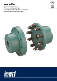
Falk Steelflex ® <strong>Grid</strong> <strong><strong>Coupling</strong>s</strong><br />
<strong>Redefining</strong> <strong>Total</strong> <strong>Coupling</strong> <strong>Value</strong><br />
(English-Metric)
Falk Steelflex ®<br />
The simplest, most cost-effective coupling<br />
The Falk name is synonymous with grid couplings, as well as using<br />
shot peening to increase fatique strength and torque ratings.<br />
Steelflex redefines total coupling value up to 7.5 million in-lb,<br />
932 000 Nm torque. Steelflex offers simpler initial installation than<br />
gear couplings, and our new HD design outlasts competitive gear<br />
couplings 2 to 1.<br />
The unique “replace in place” design eliminates the need to move<br />
hubs or re-align shafts, reducing element change-out time.<br />
When you look (see chart below) at the overall savings in initial costs,<br />
spare parts costs, and labor costs for installation, alignment and<br />
replacement - plus improved ratings and a 5 Year Heavy-Duty<br />
Warranty - it’s easy to see what Steelflex <strong>Grid</strong> <strong><strong>Coupling</strong>s</strong> have over the<br />
competition. No other coupling in the torque range can touch<br />
Steelflex for cost-effective performance and reliability.<br />
ELASTOMER<br />
DISC<br />
GEAR<br />
STEELFLEX<br />
<strong>Coupling</strong> Lifetime Operating Costs<br />
150 HP (112 KW) @ 68 RPM<br />
$2,895 <strong>Total</strong><br />
$2,390 <strong>Total</strong><br />
$5,264 <strong>Total</strong><br />
$7,717 <strong>Total</strong><br />
I I I I I I I I I<br />
0 1,000 2,000 3,000 4,000 5,000 6,000 7,000 8,000<br />
U.S. Dollars @ Suggested Consumer<br />
Production losses are not included in this chart.<br />
Initial Costs Labor Costs to Install & Align<br />
Spare Parts Costs Replacement Labor Costs<br />
Features That Give Steelflex the<br />
Lowest Lifetime Operating Cost<br />
Longer Life<br />
Tapered grids, made of high<br />
strength alloy steel, are quenched<br />
and tempered to spring hardness.<br />
The grid surface is then precision<br />
shot peened to compress the surface<br />
molecules.<br />
The effect is a dramatic increase in<br />
rating, providing reserve strength for<br />
longer life or allowing a smaller size<br />
coupling to be selected.<br />
This precision technology was<br />
originally used in the production of<br />
sophisticated aircraft components.<br />
Extended Maintenance Periods<br />
Now you can install Steelflex and<br />
lubricate it with Falk Long Term<br />
Grease (LTG) and forget periodic,<br />
routine maintenance for five years.<br />
Falk LTG grease was developed<br />
specifically for couplings. It resists<br />
the separation of the oil and thickening<br />
agent that occurs in typical<br />
greases.<br />
The initial use of Falk LTG coupling<br />
grease will eliminate routine<br />
lubrication cycles while still<br />
providing the necessary lubrication<br />
to the tapered grid.<br />
With LTG, Steellflex combines the<br />
high torque performance of a gear<br />
coupling and the low maintenance<br />
of a disc or elastomer coupling.<br />
Type HD <strong><strong>Coupling</strong>s</strong><br />
The Preferred Replacement for<br />
Gear <strong><strong>Coupling</strong>s</strong><br />
Durable Nitrile Seals are heat<br />
resistant to 275 ο F. (135 ο C.)<br />
Powder-coated covers provide<br />
chemical resistance.<br />
2
Quick, Easy Installation…<br />
Replace-In-Place Design<br />
The grid is the wearing member<br />
of a Steelflex coupling and it is a<br />
fraction of the complete coupling<br />
cost. Tapered grids are accessible<br />
through the quickly removable<br />
cover.<br />
The replace-in-place design of the<br />
replacement grids allows them to be<br />
dropped in without the need to<br />
remove or reposition hubs or realign<br />
shafts as required with gear couplings<br />
and many elastomer designs<br />
When coupling-connected equipment<br />
must be moved, the job takes<br />
longer and costs a lot more.<br />
Equipment Protection Against<br />
Shaft Misalignment<br />
The grid is free to rock, pivot and<br />
float within the hub teeth. Generous<br />
misalignment capacity is provided<br />
without producing detrimental<br />
bearing side loads created by other<br />
couplings.<br />
Equipment Protection Against<br />
Shock/Vibratory Loads<br />
Torsional flexibility is the ability of<br />
Falk Steelflex<br />
couplings to<br />
torsionally deflect LIGHT LOAD<br />
when subjected<br />
to normal shock<br />
or vibratory loads,<br />
providing flexible<br />
accommodation<br />
HEAVY LOAD<br />
to changing load<br />
conditions.<br />
Consequently,<br />
Steelflex tunes<br />
the drive system.<br />
It absorbs impact<br />
energy by spreading it over an<br />
increment of time. It damps vibration<br />
and reduces peak or shock loads<br />
by as much as 30%. It is a true<br />
shock absorber for rotary motion,<br />
relying on the predictable resilience<br />
of the steel grid for<br />
torsional flexibility.<br />
CONTACT INCREASES<br />
Steelflex HD <strong>Grid</strong> <strong><strong>Coupling</strong>s</strong> –<br />
The preferred replacement for<br />
gear couplings<br />
LOW CONTACT<br />
PIVOTS<br />
FLOATS<br />
ROCKS<br />
Versatile Designs<br />
Two cover designs are available in the popular sizes. Standard spacer,<br />
piloted, high speed, brakewheel or disc, and controlled torque<br />
designs are also available.<br />
Worldwide Availability<br />
Steelflex couplings and component parts, are available in popular sizes<br />
and types. Our distribution centers and worldwide distribution network<br />
offer the largest stock of rough bore, finish straight bore and Taperlock<br />
bushed hubs of any shaft coupling on the market. Plus, Steelflex<br />
grid couplings are warranted for 5 Years when lubricated with Falk<br />
LTG Long Term Grease.<br />
3
4<br />
Steelflex Selection Guide
Selection Guide M421-110, February 2007<br />
Table of Contents<br />
How to Select, Standard & Formula Methods . . . . . . . . 7-9<br />
Quick selection Method . . . . . . . . . . . . . . . . . 10-11<br />
Service Factors . . . . . . . . . . . . . . . . . . . . . . . 12<br />
How to Order. . . . . . . . . . . . . . . . . . . . . . . . 13<br />
T Type Steelflex <strong>Grid</strong> <strong><strong>Coupling</strong>s</strong>:<br />
Dimensions & Specifications<br />
Type T10 Close Coupled. . . . . . . . . . . . . . . . . . 14<br />
Type T20 Close Coupled . . . . . . . . . . . . . . . . . . 15<br />
Type T31 Full Spacer . . . . . . . . . . . . . . . . . . 16-17<br />
Type T35 Half Spacer . . . . . . . . . . . . . . . . . . 18-19<br />
Type T41 & LT Controlled Torque <strong>Coupling</strong> . . . . . . . . . 20<br />
Type T44 Controlled Torque Clutches . . . . . . . . . . . . 21<br />
Type T45 & T42 Piloted Controlled Torque Assemblies . . . . 22<br />
Optional Automatic Proximity Sensor Cutout Switch . . . . . 23<br />
Slip Torque Performance Charts . . . . . . . . . . . . . 24-27<br />
Type T50 Floating Shaft Assembly . . . . . . . . . . . . . . 28<br />
Type T50 Floating Shaft Selections . . . . . . . . . . . . . 29<br />
Type T63 Disc Brake . . . . . . . . . . . . . . . . . . . 30-32<br />
Type T70 High Speed . . . . . . . . . . . . . . . . . . . . 33<br />
Type T90 Flywheel. . . . . . . . . . . . . . . . . . . . . . 34<br />
Type T10/G82 Spacer. . . . . . . . . . . . . . . . . . . . 35<br />
Engineering Data<br />
Recommended Commercial Keys – Metric and Inch . . . . . 36<br />
Shaft Diameters & Ratings for 50 Hertz Metric Motors<br />
& NEMA 60 Hertz. . . . . . . . . . . . . . . . . . . . . . 36<br />
Bore Ranges With Square & Rectangular Keys . . . . . . 37-38<br />
Taper Lock Bushings for Type T Hubs & Shaft Hubs . . . . . . 39<br />
WR 2 <strong>Value</strong>s . . . . . . . . . . . . . . . . . . . . . . . . 40<br />
Misalignment Capacities . . . . . . . . . . . . . . . . . . 40<br />
Standard AISE AC & DC Mill Motor <strong>Coupling</strong> Selections . . . 41<br />
Taper and Counter Bore Limitations . . . . . . . . . . . . . 42<br />
Puller Bolt Holes . . . . . . . . . . . . . . . . . . . . . . 42<br />
Recommended Bores – Metric and Inch . . . . . . . . . 43-45<br />
<strong>Coupling</strong> Application Data Sheet . . . . . . . . . . . . . . 46<br />
Factory Warranty We’re so confident in the performance and<br />
reliability of our latest generation of Falk gear drives that we’re<br />
backing this comprehensive offering with the best standard<br />
warranty in the business. Our full, 3-year Heavy-Duty Warranty<br />
provides “shaft-to-shaft” protection on all Falk components –<br />
including bearings and seals. It’s an industry first... and one more<br />
powerful reason why Rexnord is your ultimate bottom-line drive<br />
and coupling value. Steelflex grid couplings are warranted for 5<br />
years when lubricated with Falk LTG Long Term Grease.<br />
All Falk Steelflex <strong><strong>Coupling</strong>s</strong> Possess the<br />
Following Benefits<br />
High Ratings<br />
Extended Maintenance Periods<br />
Quick Installation<br />
Easy Maintenance<br />
Versatile Design<br />
Availability<br />
Protection Against Shaft Misalignment<br />
Protection Against Shock Loads, Vibration and Thrust<br />
Loads<br />
General Information<br />
– Rexnord standards apply unless otherwise specified.<br />
– All Dimensions are for reference only and are subject to<br />
change without notice unless certified.<br />
– Unless otherwise specified, Falk coupling hubs Sizes 1020T thru<br />
1090T will be bored for CLEARANCE FIT with a setscrew OVER<br />
the keyway, and Sizes 1100T and larger will be furnished for<br />
INTERFERENCE FIT without a setscrew (see Table 27, Page 43).<br />
Recommended key sizes for the listed maximum bores are<br />
shown in Table 13 on Page 36.<br />
– Torque ratings of couplings utilizing Taper-Lock bushings can<br />
differ from those that do not. Refer to the Factory for details.<br />
– If Rexnord is to supply coupling hubs bored for Taper-Lock<br />
bushings, the bushing manufacturer MUST be noted on the<br />
order.<br />
– Consult the Factory when limited end float is required.<br />
Reference Notes<br />
† Peak torque capacity is two times the published rating. Torque<br />
ratings for hubs with bushings differ from those shown, refer to<br />
Table 19, Page 39.<br />
‡ Consult the Factory for higher speeds.<br />
Maximum bores are reduced for hubs furnished with an<br />
INTERFERENCE FIT and a setscrew OVER the keyway. Refer to<br />
Rexnord Engineering Sheet 427-105 for details.<br />
Minimum bore is the smallest bore to which a RSB hub (rough<br />
stock bore) hub can be bored. Depending upon coupling<br />
size, rough stock bore hubs may have only a blind centering<br />
hole or a through hole that will permit remachining of the<br />
hubs to the minimum bores specified.<br />
Warranty extends for 3 years from date of shipment.<br />
Copyright 2003, 2007. Rexnord Industries, LLC. All Rights Reserved. Litho in U.S.A.<br />
Steelflex and Rexnord are registered trademarks of Rexnord Industries, LLC. Falk is a trademark of<br />
Rexnord. Dodge is a registered trademark. Taper-Lock is a registered trademark of a bushing under<br />
license.<br />
The contents of this selection guide are subject to change without notice or obligation.<br />
Information contained herein should be confirmed before placing orders.<br />
© Rexnord Industries, LLC, 2003, 2007 (M421-110) 5
Falk Steelflex <strong>Grid</strong> <strong><strong>Coupling</strong>s</strong><br />
A general purpose, lubricated design that combines the economy and high torque capacity of a gear coupling with the torsional flexibility<br />
of an elastomer coupling. Backed by a 5–year lubrication warranty, Falk Steelflex couplings require no periodic maintenance when<br />
lubricated with Falk LTG (Long Term Grease) at installation. Featuring 25 sizes, Stelflex couplings can accommodate torque loads of<br />
932 000 (Nm) and shaft diameters of 508 millimeters.<br />
A double flexing, close-coupled<br />
design for use in four bearing<br />
systems. Features a horizontally split<br />
cover which allows for grid<br />
replacement without the movement of<br />
the connected equipment.<br />
(See Page 14.)<br />
Type T10 Close Coupled<br />
Type T50 Piloted<br />
For use on line shaft applications. Can<br />
be used in place of single engagement<br />
gear couplings to provide torsional<br />
resiliency and lower overall operating<br />
cost.<br />
(See Pages 28 & 29.)<br />
A double flexing design featuring a<br />
vertically split steel cover. Ideal for<br />
higher running speeds. (See Page 15.)<br />
Proven to be far superior to<br />
drum-type brakes in cost,<br />
construction and performance.<br />
(See Pages 30 thru 32.)<br />
Type T20 Close Coupled<br />
Type T63 Disc Brake<br />
Complete center section drops<br />
out for easy service of connected<br />
equipment bearings and seals.<br />
Ideal for pump applications.<br />
(See Pages 16 & 17.)<br />
Designed for operating speeds beyond<br />
those of the T10 and T20 designs.<br />
Features a one-piece cover and balanced<br />
components. (See Page 33.)<br />
Type T31 Full Spacer<br />
Type T70 High Speed<br />
An economical spacer design<br />
for easy service of connected<br />
equipment bearings and seals.<br />
Ideal for pump applications.<br />
(See Pages 18 & 19.)<br />
Used primarily to connect the<br />
flywheel of an engine to the<br />
driven machinery. It provides for<br />
higher torque ratings with<br />
resulting smaller sizes and lower<br />
costs than elastomer couplings.<br />
(See Page 34.)<br />
Type T35 Half Spacer<br />
Type T90 Flywheel<br />
Provides adjustable slipping action to<br />
protect connected equipment from<br />
shock, jams, or temporary overloads.<br />
(See Pages 20 thru 27.)<br />
Type T41, T42, T44 & T45 Controlled Torque<br />
Type T10/G82 Spacer<br />
A combination of two<br />
standard Falk couplings.<br />
Utilizes readily available<br />
components for an<br />
economical price and<br />
shorter lead time than<br />
T31/T35 couplings.<br />
(See Page 35.)<br />
Type T50 Floating Shaft<br />
Double piloted design<br />
for connecting<br />
equipment where the<br />
distance between shafts<br />
is too large for a<br />
spacer type coupling.<br />
(See Pages 28 & 29.)<br />
Type BW Brakewheel<br />
Provides a built-in braking surface right at or<br />
near the centerline of the coupling ...saves<br />
space and dollars. (See Selection Guide<br />
431-310.)<br />
WARNING! Mixing grid coupling components from different manufacturers may cause premature<br />
failure and possible personal injury or property damage from flying debris.<br />
6 (M421-110) © Rexnord Industries, LLC, 2003, 2007
How to Select<br />
Standard Selection Method (except T41/T44 &T63)<br />
The standard selection method can be used for most motor,<br />
turbine, or engine driven applications. The following information<br />
is required to select a flexible coupling:<br />
Kilowatt (kW) or torque<br />
Running rpm<br />
Application or type of equipment to be connected (motor to<br />
pump, gear drive to conveyor, etc.)<br />
Shaft diameters<br />
Shaft gaps<br />
Physical space limitations<br />
Special bore or finish information and type of fit<br />
Exceptions are High Peak Loads and Brake Applications. For<br />
these conditions use the Formula Selection Method in the<br />
next column, or consult your local Falk Representative for<br />
assistance.<br />
1. RATING: Determine system torque. If torque is not given,<br />
calculate as shown below:<br />
kW x 9549<br />
System Torque (Nm) =<br />
rpm<br />
Where kilowatt (kW) is the actual or transmitted power required<br />
by the application (if unknown, use the motor or turbine<br />
nameplate rating) and rpm is the actual speed the coupling is<br />
rotating. Applications that require rapid changes in direction or<br />
torque reversals should be referred to Rexnord Engineering.<br />
2. SERVICE FACTOR: Determine appropriate service factor from<br />
Table 4, Page 12.<br />
3. REQUIRED MINIMUM COUPLING RATING: Determine the<br />
required minimum coupling rating as shown below:<br />
Minimum <strong>Coupling</strong> Rating = S.F. (Service Factor) x Torque (Nm)<br />
4. TYPE: Refer to Page 6 and select the appropriate coupling<br />
type.<br />
5. SIZE: Turn to appropriate pages for the coupling type chosen<br />
and trace down the torque column to a value that is equal or<br />
greater than that determined in Step 3 above. The coupling<br />
size is shown in the first column.<br />
6. CHECK: Check speed (rpm), bore, gap, and dimensions.<br />
STANDARD SELECTION EXAMPLE:<br />
Select a coupling to connect a 55 kW, 1500 rpm electric motor<br />
driving a lobe type blower. Motor shaft diameter is 60 mm,<br />
blower shaft diameter is 45 mm. Shaft extensions are 140 mm<br />
and 110 mm. Selection is replacing a gear type coupling with a<br />
3 mm gap.<br />
1. DETERMINE REQUIRED RATING:<br />
55 kW x 9549<br />
System Torque (Nm) = = 350 Nm<br />
1500 rpm<br />
2. SERVICE FACTOR: From Table 4 = 1.25<br />
3. REQUIRED MINIMUM COUPLING RATING:<br />
1.25 x 350 Nm = 438 Nm<br />
4. SIZE: From Page 14 a Size 1070T is the proper selection<br />
based on a torque rating of 904 Nm exceeding the required<br />
minimum coupling rating of 438 Nm.<br />
5. CHECK: Allowable speed capacity of 4125 (1070T10)<br />
exceeds the required speed of 1500 rpm. Maximum bore<br />
capacity of 67 mm exceeds the actual shaft diameters.<br />
Type T63 Static (holding) Brake Applications<br />
1. SIZE: The brake rating must equal or exceed the application<br />
requirements. Determine the required coupling size by<br />
comparing the application loads (from Steps A and B below)<br />
to the coupling brake rating listed on Page 31. Use the<br />
highest torque value calculated to determine the coupling<br />
size.<br />
A. For normal service applications, use the application torque in<br />
Nm.<br />
Transmitted kW x 9549<br />
System Torque (Nm) =<br />
rpm<br />
B. For repetitive high peak load applications, use the system peak<br />
torque in Nm. (Repetitive is defined as more than 1000 times<br />
during the expected coupling life.)<br />
2. CALIPER TORQUE BRAKE RATING: For the coupling size<br />
selected, compare the caliper brake torque rating on Page 31<br />
to the holding torque requirement of the application. Rexnord<br />
recommends that the caliper torque rating (min.) be at least<br />
two times the holding torque requirement for static<br />
applications to compensate for the possibility of foreign<br />
matter on the disc surfaces, loss of condition of the brake pad<br />
surfaces, or other conditions that may affect the holding<br />
ability of the caliper brake.<br />
Caliper brakes and brake discs listed are designed primarily<br />
for static and/or emergency brake applications. NOTE:<br />
Check brake system and lining wear after emergency stops.<br />
They can, however, also be used for dynamic stopping if only<br />
used occasionally, such as shutting down the equipment for<br />
the day or between shift changes. For stopping high inertia<br />
systems or for applications that require more frequent<br />
stopping, consult your local Rexnord Representative.<br />
3. CHECK: Check maximum bores, speeds, and dimensions.<br />
Type T63 Stopping Or Service Brake Applications<br />
1. SIZE: The coupling brake rating must equal or exceed the<br />
application requirements. Determine the required coupling<br />
size by comparing the application loads (from Steps A, B and<br />
C below) to the coupling brake rating listed on Page 28. Use<br />
the highest torque value calculated to determine the coupling<br />
size.<br />
A. For the selected caliper brake and disc diameter ,use the<br />
maximum brake torque in Nm.<br />
B. For normal service applications, use the application torque in<br />
Nm.<br />
Transmitted kW x 9549<br />
System Torque (Nm) =<br />
rpm<br />
C. For repetitive high peak load applications, use the system<br />
peak torque in Nm (Repetitive is defined as more than 1000<br />
times during the expected coupling life.)<br />
2. CHECK: Check maximum bores, speeds, and dimensions.<br />
© Rexnord Industries, LLC, 2003, 2007 (M421-110) 7
How to Select<br />
Formula Selection Method (except T41/T44 & T63)<br />
The Standard Selection Method can be used for most coupling<br />
selections. The procedures below should be used for:<br />
High Peak Loads.<br />
Brake Applications (where the brake disc or brake wheel is to<br />
be an integral part of the coupling, consult the Factory for<br />
design options).<br />
Providing system peak torque and frequency, duty cycle, and<br />
brake torque rating will allow for a more refined selection using<br />
the Formula Selection Method.<br />
1. HIGH PEAK LOADS: Use one of the following formulas for<br />
applications using motors with torque characteristics that are higher<br />
than normal; applications with intermittent operations, shock<br />
loading, inertia effects due to starting and stopping and or system<br />
induced repetitive high peak torques. System Peak Torque is the<br />
maximum torque that can exist in the system. Select a coupling with<br />
a torque rating equal to or greater than selection torque calculated<br />
below.<br />
A. NON-REVERSING HIGH PEAK TORQUE<br />
Selection Torque (Nm) = System Peak Torque<br />
or<br />
System Peak kW x 9549<br />
Selection Torque (Nm) =<br />
rpm<br />
B. REVERSING HIGH PEAK TORQUE<br />
Selection Torque (Nm) =2xSystem Peak Torque<br />
or<br />
2 x Peak kW x 9549<br />
Selection Torque (Nm) =<br />
rpm<br />
C. OCCASIONAL PEAK TORQUES (Non-Reversing) If a system<br />
peak torque occurs less than 1000 times during the expected<br />
coupling life, use the following formula:<br />
Selection Torque (Nm) = 0,5 x System Peak Torque<br />
or<br />
0,5 x Peak kW x 9549<br />
Selection Torque (Nm) =<br />
rpm<br />
For reversing service select per step B.<br />
2. BRAKE APPLICATIONS: If the torque rating of the brake<br />
exceeds the motor torque use the brake rating as follows:<br />
Selection Torque (Nm) = Brake Torque Rating x S.F.<br />
FORMULA SELECTION EXAMPLE — High Peak Load:<br />
Select a coupling for reversing service to connect a gear drive low<br />
speed shaft to a runout mill table roll. The electric motor rating is 37<br />
kW at the base speed and the system peak torque at the coupling is<br />
estimated to be 17 000 Nm. <strong>Coupling</strong> speed is 77 rpm at the motor<br />
base speed. The drive shaft diameter is 100 mm with a key of<br />
28 mm x 16 mm. The runout table roll diameter is 135 mm with a<br />
key of 36 mm x 20 mm. Maximum shaft gap (BE) is 180 mm long.<br />
1. TYPE: Refer to Page 6 and select the appropriate coupling type.<br />
2. REQUIRED MINIMUM COUPLING RATING:<br />
Use the Reversing High Peak Torque formula in Step 1B.<br />
2 x 17 000 = 34 000 = Selection Torque<br />
3. SIZE: From Page 19, Size 1150T35 with a torque rating of<br />
39 800 exceeds the selection torque of 34 000 Nm.<br />
4. CHECK: The 1150T35 has a maximum BE dimension of<br />
187,5 mm; the shaft hub has a maximum bore of 270 mm<br />
(Table 16, Page 37 ); the T hub has a maximum bore of 215<br />
mm (Table 15, Page 37); and the allowable speed of 1500<br />
rpm and the dimensions on Page 19 meet the requirements.<br />
TABLE 1 — <strong>Coupling</strong> Ratings & Allowable Speeds<br />
<strong>Coupling</strong><br />
Size<br />
<br />
kW/RPM <br />
Torque<br />
Rating<br />
(Nm) †<br />
T10<br />
Allowable Speeds —rpm ‡<br />
T20 &<br />
T50 <br />
T31, T35 &<br />
T10/G82<br />
1020T 0,005 52 4500 6000 3600 . . .<br />
1030T 0,016 149 4500 6000 3600 10000<br />
1040T 0,026 249 4500 6000 3600 . . .<br />
1050T 0,046 435 4500 6000 3600 9000<br />
1060T 0,072 684 4350 6000 3600 . . .<br />
1070T 0,104 994 4125 5500 3600 8200<br />
1080T 0,215 2 050 3600 4750 3600 7100<br />
1090T 0,39 3 730 3600 4000 3600 6000<br />
1100T 0,657 6 280 2440 3250 2440 4900<br />
1110T 0,976 9 320 2250 3000 2250 4500<br />
1120T 1,43 13 700 2025 2700 2025 4000<br />
1130T 2,08 19 900 1800 2400 1800 3600<br />
1140T 2,99 28 600 1650 2200 1650 3300<br />
1150T 4,16 39 800 1500 2000 1500 . . .<br />
1160T 5,86 55 900 1350 1750 1350 . . .<br />
1170T 7,81 74 600 1225 1600 1225 . . .<br />
1180T 10,8 103 000 1100 1400 1100 . . .<br />
1190T 14,3 137 000 1050 1300 1050 . . .<br />
1200T 19,5 186 000 900 1200 900 . . .<br />
1210T 26 249 000 820 . . . . . . . . .<br />
1220T 35,1 336 000 730 . . . . . . . . .<br />
1230T 45,6 435 000 680 . . . . . . . . .<br />
1240T 58,6 559 000 630 . . . . . . . . .<br />
1250T 78,1 746 000 580 . . . . . . . . .<br />
1260T 97,6 932 000 540 . . . . . . . . .<br />
Refer to Page 5 for General Information and Reference notes.<br />
kW/RPM and torque rating values for hubs with Taper Lock ® bushings differ from<br />
those shown above. Refer to Table 19, Page 39.<br />
Speeds shown above are for single Type T50 couplings; speeds for Type T50<br />
Floating Shaft couplings are shown in Table 12, Page 29.<br />
T70<br />
8 (M421-110) © Rexnord Industries, LLC, 2003, 2007
How to Select<br />
Type T41 Controlled Torque <strong><strong>Coupling</strong>s</strong> & T44<br />
Controlled Torque Clutches<br />
Type T41 Controlled Torque <strong><strong>Coupling</strong>s</strong><br />
1. RUNNING TORQUE: Calculate normal running torque<br />
Required kW x 9549<br />
Running Torque (Nm) =<br />
rpm<br />
2. SLIP TORQUE: Slip torque = Running Torque x 150%<br />
(Overload Setting.) Rexnord recommends a minimum 150%<br />
overload setting for steady or moderate shock load<br />
applications. For heavy shock load applications, a 200% or<br />
greater overload setting may be required.<br />
3. COUPLING SIZE: Refer to Table 8, Page 20 — Trace down<br />
the Slip Torque column to a figure equal to or in excess of the<br />
calculated slip torque determined in Step 2. Read the coupling<br />
size in the next column.<br />
4. CHECK:<br />
A. Check shaft diameters against coupling maximum bores<br />
shown in Table 8, Page 20. If selection does not have<br />
adequate bore capacity, refer to Table 15, Page 37 or Table<br />
17, Page 38 for maximum bores with square or rectangular<br />
keys, or select the next larger size coupling.<br />
B. Check the required speed against the allowable speed<br />
shown in Table 8, Page 20. If a higher speed is required,<br />
refer application details to the local Rexnord representative.<br />
C. Check allowable slip torque times from Slip Torque<br />
Performance Charts on Pages 24 through 27. The length of<br />
time a coupling can slip without exceeding its thermal<br />
capacity is a function of the slip torque setting and the<br />
operating speed. An automatic cutout switch, Page 23, can<br />
be provided when damaging thermal conditions exist.<br />
D. Check application dimension requirements against selected<br />
coupling dimensions shown on Page 20.<br />
E. Check usable shaft length to the coupling hub lengths on<br />
Page 18. If necessary, overhang hubs within the limits<br />
specified on Page 23.<br />
SELECTION EXAMPLE:<br />
Select a controlled torque coupling to connect a 15,0 kW, 1500<br />
rpm, 160L frame motor to the high speed shaft of a gear drive<br />
driving a screw feeder. Motor shaft diameter is 42 mm with a<br />
usable shaft length of 110 mm. Drive high speed shaft diameter<br />
is 35 mm with usable shaft length of 65 mm.<br />
1. RUNNING TORQUE: From Step 1 above:<br />
15,0 kW x 9549<br />
Running Torque (Nm) = = 95,5 Nm<br />
1500 RPM<br />
2. SLIP TORQUE: From Step 2 above: Slip Torque = 95,5 Nm x<br />
150% = 143,2 Nm.<br />
3. SIZE: From Table 8, Page 20, the minimum size coupling is the<br />
Size 40T41, which has a maximum slip torque of 167 Nm.<br />
4. CHECK:<br />
A. From Table 8, Page 20, the Size 40T41, T41 hub has a<br />
maximum bore capacity of only 35 mm and the T hub<br />
maximum bore capacity is 43 mm. The preferred mounting<br />
arrangement is to have the T41 hub on the motor (for<br />
optimum cooling during slippage). Therefore, select the size<br />
50T41 with a T41 hub maximum bore capacity of 45 mm,<br />
as compared to the motor shaft diameter of 42mm, and the<br />
slip torque required is within its range.<br />
B. Allowable Speed of 3600 rpm exceeds required 1500 rpm.<br />
C. From Page 24, the Size 50T41 with slip torque setting of<br />
143,2 Nm and running speed of 1500 rpm will permit 27<br />
seconds slip if followed by 9 minutes of non-slip.<br />
D. See Page 20 for dimensions.<br />
E. Usable shaft length of motor is 110 mm and “W”<br />
dimension for T41 hub is 87,4 mm, therefore no overhang<br />
required. Usable shaft length of drive is 65 mm and “C”<br />
dimension of “T” hub is 60,5 mm, therefore no overhang<br />
required.<br />
Type T44 Controlled Torque Clutches<br />
1. RUNNING TORQUE<br />
Required kW x 9549<br />
Running Torque (Nm) =<br />
rpm<br />
2. SLIP TORQUE: Slip Torque = Running Torque x 150%<br />
(Overload Setting.) Rexnord recommends a minimum 150%<br />
overload setting for steady or moderate shock load<br />
applications. For heavy shock load applications a 200% or<br />
greater overload setting may be required.<br />
3. CLUTCH SIZE: Refer to Table 9, Page 21 — Trace down the<br />
Slip Torque column to a figure equal to or in excess of the<br />
calculated slip torque determined in Step 2. Read clutch size<br />
in the next column.<br />
A. Check shaft diameters against clutch maximum bores<br />
shown in Table 9. If selection does not have adequate bore<br />
capacity refer to Table 17, Page 38 for maximum bores with<br />
square or rectangular keys, or select the next larger size clutch.<br />
B. Check the required speed against the allowable speed<br />
shown in Table 9. If a higher speed is required, refer<br />
application details to the local Rexnord representative.<br />
C. Check allowable slip torque times from Slip Torque<br />
Performance Charts on Pages 24 through 27. The length of<br />
time a clutch can slip without exceeding its thermal capacity<br />
is a function of the slip torque setting and the operating<br />
speed. An automatic cutout switch, Page 23, can be<br />
provided when damaging thermal conditions exist.<br />
D. Check application dimension requirements against selected<br />
clutch dimensions shown on Page 21.<br />
E. Check usable shaft length to the clutch hub length on Page<br />
19. If necessary, overhang hub within the limits specified on<br />
Page 23.<br />
© Rexnord Industries, LLC, 2003, 2007 (M421-110) 9
Quick Selection Method<br />
1. Select <strong>Coupling</strong> Type<br />
Refer to Page 6 and select the type of coupling to suit your<br />
application. If an application requires a special purpose<br />
coupling, refer application details to the local Rexnord<br />
Representative.<br />
2. Determine Service Factor.<br />
A. For MOTOR, TURBINE or ENGINE driven applications, refer<br />
to Tables 4 and 5.<br />
B. For BRAKE or HIGH PEAK LOAD applications, refer to the<br />
Formula Selection Method shown on Page 8.<br />
3. Determine Equivalent Power.<br />
RefertoTable4—Under the actual kW required and opposite<br />
the service factor determined in Step 2, read the equivalent kW.<br />
4. Determine <strong>Coupling</strong> Size.<br />
A. Refer to Table 4—Trace horizontally from the required<br />
speed to a hp value equal to or larger than the equivalent<br />
kilowatts determined in Step 3. Read the coupling size at top<br />
of column.<br />
TABLE 2 — Equivalent Power = (Actual kW x Service Factor)<br />
Service<br />
Factor<br />
‡<br />
Actual kW<br />
0.25 0.37 0.55 0.75 1.1 1.5 2.2 3 4 5.5 7.5 9.2 11 15 18.5 22 30 37 45 55 75 90 110 132 150 185 200 220 250 300 330<br />
1.00 0.25 0.37 0.55 0.75 1.1 1.5 2.2 3 4 5.5 7.5 9.2 11 15 18.5 22 30 37 45 55 75 90 110 132 150 185 200 220 250 300 330<br />
1.25 0.31 0.46 0.69 0.9 1.4 1.9 2.8 3.8 5 6.9 9.4 11.5 13.8 18.8 23.1 27.5 37.5 46.3 56.3 68.8 93.8 113 138 165 188 231 250 275 313 375 413<br />
1.50 0.38 0.56 0.83 1.1 1.7 2.3 3.3 4.5 6.0 8.3 11.3 13.8 16.5 22.5 27.8 33.0 45.0 55.5 67.5 82.5 113 135 165 198 225 278 300 330 375 450 495<br />
1.75 0.44 0.65 0.96 1.3 1.9 2.6 3.9 5.3 7.0 9.6 13.1 16.1 19.3 26.3 32.4 38.5 52.5 64.8 78.8 96.3 131 158 193 231 263 324 350 385 438 525 578<br />
2.00 0.50 0.74 1.1 1.5 2.2 3.0 4.4 6.0 8.0 11.0 15.0 18.4 22.0 30.0 37.0 44.0 60.0 74.0 90.0 110 150 180 220 264 300 370 400 440 500 600 660<br />
2.50 0.63 0.93 1.4 1.9 2.8 3.8 5.5 7.5 10 13.8 18.8 23.0 27.5 37.5 46.3 55.0 75.0 92.5 113 138 188 225 275 330 375 463 500 550 625 750 825<br />
3.00 0.75 1.1 1.7 2.3 3.3 4.5 6.6 9.0 12 16.5 22.5 27.6 33.0 45.0 55.5 66.0 90.0 111 135 165 225 270 330 396 450 555 600 660 750 900 990<br />
3.50 0.88 1.3 1.9 2.6 3.9 5.3 7.7 10.5 14 19.3 26.3 32.2 38.5 52.5 64.8 77.0 105 130 158 193 263 315 385 462 525 648 700 770 875 1050 1155<br />
‡ For service factors not listed. Equivalent kW = Actual kW x Service Factor.<br />
TABLE3—<strong>Coupling</strong>Selection...BasedonEquivalent kW Ratings<br />
Max Bore (mm)<br />
Max Speed T10<br />
Max Speed T20<br />
Torque (Nm)<br />
kW / rpm<br />
RPM<br />
1020T 1030T 1040T 1050T 1060T 1070T 1080T 1090T 1000T 1100T 1120T 1130T<br />
28<br />
4500 rpm<br />
6000 rpm<br />
52<br />
0,005<br />
35<br />
4500 rpm<br />
6000 rpm<br />
149<br />
0.,016<br />
43<br />
4500 rpm<br />
6000 rpm<br />
249<br />
0,026<br />
50<br />
4500 rpm<br />
6000 rpm<br />
435<br />
0,046<br />
56<br />
4350 rpm<br />
6000 rpm<br />
685<br />
0,072<br />
67<br />
4125 rpm<br />
5500 rpm<br />
995<br />
0,104<br />
kW Ratings<br />
80<br />
3600 rpm<br />
4750 rpm<br />
2050<br />
0,215<br />
95<br />
3600 rpm<br />
4000 rpm<br />
3730<br />
0,39<br />
110<br />
2440 rpm<br />
3250 rpm<br />
6275<br />
0,657<br />
120<br />
2250 rpm<br />
3000 rpm<br />
9320<br />
0,976<br />
140<br />
2025 rpm<br />
2700 rpm<br />
13670<br />
1,43<br />
170<br />
1800 rpm<br />
2400 rpm<br />
19885<br />
2,08<br />
4500 24.5 70.2 117 205 322 469 966<br />
3600 19.6 56.2 94 164 258 375 773 1410 2370<br />
3000 16.3 46.8 78 137 215 313 644 1170 1970 2930 4290<br />
2500 13.6 39.0 65.2 114 179 260 537 977 1650 2440 3580 5210<br />
2100 11.4 32.8 54.8 96 150 219 451 820 1380 2050 3010 4370<br />
1800 9.8 28.1 46.9 82 129 188 386 703 1180 1760 2580 3750<br />
1750 9.5 27.3 45.6 80 125 182 376 684 1150 1710 2510 3640<br />
1450 7.9 22.6 37.8 66.1 104 151 311 566 954 1420 2080 3020<br />
1170 6.4 18.3 30.5 53.3 84 122 251 457 770 1140 1670 2440<br />
1000 5.4 15.6 26.1 45.6 72 104 215 391 658 976 1430 2080<br />
870 4.7 13.6 22.7 39.6 62.3 91 187 340 572 849 1250 1810<br />
720 3.9 11.2 18.8 32.8 51.6 75 155 281 474 703 1030 1500<br />
650 3.5 10.1 16.9 29.6 46.5 67.7 140 254 428 634 931 1350<br />
580 3.2 9.1 15.1 26.4 41.5 60.4 125 227 382 566 830 1210<br />
520 2.8 8.1 13.6 23.7 37.2 54.2 112 203 342 508 744 1080<br />
420 2.3 6.6 11.0 19.1 30.1 43.8 90 164 276 410 601 875<br />
350 1.9 5.5 9.1 15.9 25.1 36.5 75 137 230 342 501 729<br />
280 1.5 4.4 7.3 12.8 20.0 29.2 60.1 109 184 273 401 583<br />
230 1.3 3.6 6.0 10.5 16.5 24.0 49.4 90 151 224 329 479<br />
190 1.0 3.0 5.0 8.7 13.6 19.8 40.8 74.2 125 185 272 396<br />
155 0.8 2.4 4.0 7.1 11.1 16.2 33.3 60.5 102 151 222 323<br />
125 0.68 2.0 3.3 5.7 9.0 13.0 26.8 48.8 82 122 179 260<br />
100 0.54 1.6 2.6 4.6 7.2 10.4 21.5 39.1 65.8 98 143 208<br />
84 0.46 1.3 2.2 3.8 6.0 8.8 18.0 32.8 55.3 82 120 175<br />
68 0.37 1.06 1.8 3.1 4.9 7.1 14.6 26.6 44.7 66.4 97 142<br />
56 0.30 0.87 1.5 2.6 4.0 5.8 12.0 21.9 36.8 54.7 80 117<br />
45 0.25 0.70 1.2 2.0 3.2 4.7 9.7 17.6 29.6 43.9 64.4 94<br />
37 0.20 0.58 1.0 1.7 2.6 3.9 7.9 14.5 24.3 36.1 53.0 77<br />
30 0.16 0.47 0.8 1.4 2.1 3.1 6.4 11.7 19.7 29.3 42.9 62.5<br />
25 0.14 0.39 0.65 1.1 1.8 2.6 5.4 9.8 16.5 24.4 35.8 52.1<br />
20 0.11 0.31 0.52 0.91 1.4 2.1 4.3 7.8 13.2 19.5 28.6 41.6<br />
16.5 0.090 0.26 0.43 0.75 1.2 1.7 3.5 6.4 10.9 16.1 23.6 34.4<br />
13.5 0.074 0.21 0.35 0.61 0.97 1.4 2.9 5.3 8.9 13.2 19.3 28.1<br />
11 0.060 0.17 0.29 0.50 0.79 1.1 2.4 4.3 7.2 10.7 15.7 22.9<br />
9 0.049 0.14 0.23 0.41 0.64 0.94 1.9 3.5 5.9 8.8 12.9 18.7<br />
7.5 0.041 0.12 0.20 0.34 0.54 0.78 1.6 2.9 4.9 7.3 10.7 15.6<br />
5 0.027 0.08 0.13 0.23 0.36 0.52 1.1 2.0 3.3 4.9 7.2 10.4<br />
T20 Only.<br />
10 (M421-110) © Rexnord Industries, LLC, 2003, 2007
B. Check shaft diameters against coupling maximum bores<br />
shown in Tables 15 thru 18 for the type of coupling selected.<br />
If a larger bore is required, select a larger coupling.<br />
C. Check the required speed against the allowable speed<br />
shown in Table 1 for the type of coupling selected. For Type<br />
T50 Floating Shaft design, check the allowable speed from<br />
Table 12 on Page 29. If a higher speed is required, refer<br />
application details to the local Rexnord Representative.<br />
D. Check application dimension requirements against selected<br />
coupling type dimensions shown on Pages 14 thru 35.<br />
Example:<br />
Select a Steelflex coupling to connect the low speed shaft of a<br />
gear drive to a belt conveyor. The motor is 250 kW and the low<br />
speed shaft RPM is 68. The gear drive shaft is 160 mm and the<br />
conveyor shaft is 180 mm.<br />
1. Select <strong>Coupling</strong> Type — To connect close coupled shafts, and<br />
to accommodate anticipated shaft misalignment, the double<br />
engagement Type T10 coupling shown on Page 14, is the<br />
selection.<br />
2. Determine Service Factor — From Table 4, Page 12, the<br />
service factor is 1.0.<br />
3. Determine Equivalent HP — From Table 2, Page 10, the<br />
equivalent power is 250 kW.<br />
4. Select coupling Size — (A) From Table 3, Page 11, the<br />
coupling size is 1150T10 for 68RPM. (B) From Table 3, the<br />
maximum bore of 215 mm, and allowable speed of 1500<br />
rpm are all satisfactory. Check other dimensional information<br />
on Page 14 against the available shaft lengths, shaft gaps,<br />
and diameter restrictions.<br />
TABLE3—<strong>Coupling</strong>Selection...BasedonEquivalent kW Ratings (Continued)<br />
Max Bore (mm)<br />
Max Speed T10<br />
Max Speed T20<br />
Torque (Nm)<br />
kW / rpm<br />
RPM<br />
1140T 1150T 1160T 1170T 1180T 1190T 1200T 1210T 1220T 1230T 1240T 1250T 1260<br />
200<br />
1650 rpm<br />
2200 rpm<br />
28585<br />
2,99<br />
215<br />
1500 rpm<br />
2000 rpm<br />
39770<br />
4,16<br />
240<br />
1350 rpm<br />
1800 rpm<br />
55930<br />
5,86<br />
280<br />
1225 rpm<br />
1600 rpm<br />
74570<br />
7,81<br />
300<br />
1100 rpm<br />
...<br />
103400<br />
10,8<br />
335<br />
1050 rpm<br />
...<br />
136710<br />
14,3<br />
360<br />
900 rpm<br />
...<br />
186430<br />
19,5<br />
kW Ratings<br />
390<br />
820 rpm<br />
...<br />
248570<br />
26<br />
420<br />
730 rpm<br />
...<br />
335570<br />
35,1<br />
450<br />
680 rpm<br />
...<br />
435000<br />
45,6<br />
480<br />
630 rpm<br />
...<br />
559300<br />
58,6<br />
<br />
580 rpm<br />
...<br />
745700<br />
78,1<br />
4500<br />
3600<br />
3000<br />
2500<br />
2100 6300 8760<br />
1800 5400 7510 10500<br />
1750 5250 7300 10200 13700<br />
1450 4350 6050 8490 11300<br />
1170 3510 4880 6850 9140<br />
1000 3000 4170 5860 7810 10800 14300<br />
870 2610 3630 5100 6790 9420 12500 17000<br />
720 2160 3000 4220 5620 7800 10300 14100 18800 25300<br />
650 1950 2710 3810 5080 7040 9310 12700 17000 22900 29600<br />
580 1740 2420 3400 4530 6280 8300 11300 15100 20400 26400 33900 45300<br />
520 1560 2170 3050 4060 5630 7440 10200 13600 18300 23700 30400 40600 50800<br />
420 1260 1750 2460 3280 4550 6010 8200 11000 14800 19100 24600 32800 41000<br />
350 1050 1460 2050 2730 3790 5010 6830 9140 12300 15900 20500 27300 34200<br />
280 840 1170 1640 2190 3030 4010 5470 7310 9860 12800 16400 21900 27300<br />
230 690 959 1350 1800 2490 3290 4490 6000 8100 10500 13500 18000 22500<br />
190 570 792 1110 1480 2060 2720 3710 4960 6690 8660 11100 14800 18500<br />
155 465 646 908 1210 1680 2220 3030 4050 5460 7060 9070 12100 15100<br />
125 375 521 732 976 1350 1790 2440 3260 4400 5690 7310 9760 12200<br />
100 300 417 586 781 1080 1430 1950 2610 3520 4560 5850 7810 9760<br />
84 252 350 492 656 910 1200 1640 2190 2960 3830 4910 6560 8200<br />
68 204 284 398 531 736 974 1330 1770 2390 3100 3980 5310 6640<br />
56 168 234 328 437 606 802 1090 1460 1970 2550 3280 4370 5470<br />
45 135 188 264 351 487 644 879 1170 1580 2050 2630 3510 4390<br />
37 111 154 217 289 401 530 722 966 1300 1690 2160 2890 3610<br />
30 90.0 125 176 234 325 429 586 783 1060 1370 1760 2340 2930<br />
25 75.0 104 146 195 271 358 488 653 880 1140 1460 1950 2440<br />
20 60.0 83 117 156 217 286 390 522 704 911 1170 1560 1950<br />
16.5 49.5 68.8 97 129 179 236 322 431 581 752 965 1290 1610<br />
13.5 40.5 56.3 79 105 146 193 264 352 475 615 790 1050 1320<br />
11 33.0 45.9 64.4 85.9 119 157 215 287 387 501 644 859 1070<br />
9 27.0 37.5 52.7 70.3 97 129 176 235 317 410 527 703 878<br />
7.5 22.5 31.3 81 107 146 196 264 342 439 586 732<br />
5 15.0 20.9 29.3 39.0 54 72 98 131 176 228 293 390 488<br />
Refer to Falk.<br />
T20 Only.<br />
<br />
540 rpm<br />
...<br />
932100<br />
97,6<br />
© Rexnord Industries, LLC, 2003, 2007 (M421-110) 11
Service Factors<br />
TABLE4—Flexible<strong>Coupling</strong>ServiceFactors for Motor and Turbine Drives<br />
Service factors listed are typical values based on normal operation of the drive systems.<br />
Alphabetical listing of applications<br />
Alphabetical listing of industries<br />
Service<br />
Factor<br />
AERATOR ..........................................2.0<br />
AGITATORS<br />
Vertical and Horizontal<br />
Screw, Propeller, Paddle ...............1.0<br />
BARGE HAUL PULLER ......................1.5<br />
BLOWERS<br />
Centrifugal ......................................1.0<br />
Lobe or Vane ...................................1.25<br />
CAR DUMPERS .................................2.5<br />
CAR PULLERS....................................1.5<br />
CLARIFIER OR CLASSIFIER ..............1.0<br />
COMPRESSORS<br />
Centrifugal ......................................1.0<br />
Rotary, Lobe or Vane........................1.25<br />
Rotary, Screw ...................................1.0<br />
Reciprocating<br />
Direct Connected..............Refer to Factory<br />
Without Flywheel...............Refer to Factory<br />
With Flywheel and Gear<br />
between Compressor<br />
and Prime Mover<br />
1 cylinder, single acting.............3.0<br />
1 cylinder, double acting...........3.0<br />
2 cylinders, single acting ...........3.0<br />
2 cylinders, double acting .........3.0<br />
3 cylinders, single acting ...........3.0<br />
3 cylinders, double acting .........2.0<br />
4 or more cly., single act...........1.75<br />
4 or more cyl., double act. ........1.75<br />
CONVEYORS<br />
Apron, Assembly, Belt, Chain,<br />
Flight, Screw.................................1.0<br />
Bucket .............................................1.25<br />
Live Roll, Shaker and<br />
Reciprocating ...............................3.0<br />
s¨CRANES AND HOIST<br />
Main Hoist................................. 1.75<br />
Skip Hoist....................................1.75<br />
Slope...............................................1.5<br />
Bridge, Travel or Trolley ...................1.75<br />
DYNAMOMETER...............................1.0<br />
ELEVATORS<br />
Bucket, Centrifugal Discharge ..........1.25<br />
Freight or Passenger..........Not Approved<br />
Gravity Discharge ............................1.25<br />
ESCALATORS ................... Not Approved<br />
EXCITER, GENERATOR..................... 1.0<br />
EXTRUDER, PLASTIC......................... 1.5<br />
FANS<br />
Centrifugal ......................................1.0<br />
Cooling Tower .................................2.0<br />
Forced Draft — Across the<br />
Line start ......................................1.5<br />
Forced Draft Motor<br />
Driven thru fluid or<br />
electric slip clutch .........................1.0<br />
Gas Recirculating.............................1.5<br />
Induced Draft with damper<br />
control or blade cleaner................1.25<br />
Induced Draft without controls ..........2.0<br />
FEEDERS<br />
Apron, Belt, Disc, Screw ...................1.0<br />
Reciprocating...................................2.5<br />
GENERATORS<br />
Even Load........................................1.0<br />
Hoist or Railway Service ...................1.5<br />
Service<br />
Factor<br />
Welder Load ....................................2.0<br />
HAMMERMILL ...................................1.75<br />
LAUNDRY WASHER OR<br />
TUMBLER .......................................2.0<br />
LINE SHAFTS<br />
Any Processing Machinery ................1.5<br />
MACHINE TOOLS<br />
Auxiliary and Traverse Drive .............1.0<br />
Bending Roll, Notching Press,<br />
Punch Press, Planer, Plate<br />
Reversing .....................................1.75<br />
Main Drive.......................................1.5<br />
MAN LIFTS ....................... Not Approved<br />
METAL FORMING MACHINES<br />
Continuous Caster...............................1.75<br />
Draw Bench Carriage and<br />
Main Drive ...................................2.0<br />
Extruder ...........................................2.0<br />
Farming Machine and<br />
Forming Mills ...............................2.0<br />
Slitters .............................................1.0<br />
Wire Drawing or Flattening...............1.75<br />
Wire Winder ....................................1.5<br />
Coilers and Uncoilers.......................1.5<br />
MIXERS (see Agitators)<br />
Concrete .........................................1.75<br />
Muller..............................................1.5<br />
PRESS, PRINTING .............................1.5<br />
PUG MILL ..........................................1.75<br />
PULVERIZERS<br />
Hammermill and Hog.......................1.75<br />
Roller...............................................1.5<br />
PUMPS<br />
Boiler Feed ......................................1.5<br />
Centrifugal —<br />
Constant Speed ............................1.0<br />
Frequent Speed Changes<br />
under Load ...............................1.25<br />
Descaling, with accumulators ...........1.25<br />
Gear, Rotary, or Vane ......................1.25<br />
Reciprocating, Plunger Piston<br />
1 cyl., single or double act............3.0<br />
2 cyl., single acting.......................2.0<br />
2 cyl., double acting.....................1.75<br />
3 or more cylinders.......................1.5<br />
Screw Pump, Progressing Cavity...........1.25<br />
Vacuum Pump .....................................1.25<br />
SCREENS<br />
Air Washing.....................................1.0<br />
Grizzly .............................................2.0<br />
Rotary Coal or Sand.........................1.5<br />
Vibrating..........................................2.5<br />
Water ..............................................1.0<br />
SKI TOWS & LIFTS ............Not Approved<br />
STEERING GEAR...............................1.0<br />
STOKER .............................................1.0<br />
TIRE SHREDDER................................1.50<br />
TUMBLING BARREL ..........................1.75<br />
WINCH, MANEUVERING<br />
Dredge, Marine ...............................1.5<br />
WINDLASS........................................1.5<br />
WOODWORKING<br />
MACHINERY..................................1.0<br />
WORK LIFT PLATFORMS...Not Approved<br />
For engine drives, refer to Table 5. Electric motors, generators, engines,<br />
compressors and other machines fitted with sleeves or straight roller bearings<br />
usually require limited end float couplings. If in doubt, provide axial clearances and<br />
centering forces to the Factory for a recommendation.<br />
For balanced opposed design, refer to the Factory.<br />
If people are occasionally transported, refer to the Factory for the selection of the<br />
proper size coupling.<br />
For high peak load applications (such as Metal Rolling Mills) refer to the Factory.<br />
TABLE 5 — Engine Drive Service Factors <br />
Service Factors for engine drives are those required for applications where<br />
good flywheel regulation prevents torque fluctuations greater than ±20%. For<br />
drives where torque fluctuations are greater or where the operation is near a<br />
serious critical or torsional vibration, a mass elastic study is necessary.<br />
No. of Cylinders 4 or 5 6 or more <br />
Table 2 S.F. 1.0 1.25 1.5 1.75 2.0 1.0 1.25 1.5 1.75 2.0<br />
Engine S.F. 2.0 2.25 2.5 2.75 3.0 1.5 1.75 2.0 2.25 2.5<br />
To use Table 5, first determine application service factor from Table 4. Use that<br />
factor to determine ENGINE Service Factor from Table 5. When service factor<br />
from Table 4 is greater than 2.0, or where 1, 2, or 3 cylinder engines are<br />
involved, refer complete application details to Rexnord Engineering.<br />
Service<br />
Factor<br />
AGGREGATE PROCESSING,<br />
CEMENT, MINING KILNS;<br />
TUBE, ROD AND BALL MILLS<br />
Direct or on L.S. shaft of<br />
Reducer, with final drive<br />
Machined Spur Gears...................2.0<br />
Single Helical or<br />
Herringbone Gears ...................1.75<br />
Conveyors, Feeders, Screens,<br />
Elevators ...................See General Listing<br />
Crushers, Ore or Stone ....................2.5<br />
Dryer, Rotary....................................1.75<br />
Grizzly .............................................2.0<br />
Hammermill or Hog .........................1.75<br />
Tumbling Mill or Barrel.....................1.75<br />
BREWING AND DISTILLING<br />
Bottle and Can<br />
Filling Machines ...........................1.0<br />
Brew Kettle.......................................1.0<br />
Cookers, Continuous Duty................1.25<br />
Lauter Tub .......................................1.5<br />
Mash Tub ........................................1.25<br />
Scale Hopper, Frequent Peaks ..........1.75<br />
CLAY WORKING INDUSTRY<br />
Brick Press, Briquette Machine,<br />
Clay Working Machine,<br />
Pug Mill .......................................1.75<br />
DREDGES<br />
Cable Reel.......................................1.75<br />
Conveyors .......................................1.25<br />
Cutter head, Jig Drive ......................2.0<br />
Maneuvering Winch .........................1.5<br />
Pumps (uniform load) .......................1.5<br />
Screen Drive, Stacker .......................1.75<br />
Utility Winch ....................................1.5<br />
FOOD INDUSTRY<br />
Beet Slicer........................................1.75<br />
Bottling, Can Filling Machine ...........1.0<br />
Cereal Cooker .................................1.25<br />
Dough Mixer, Meat Grinder .............1.75<br />
LUMBER<br />
Band Resaw .....................................1.5<br />
Circular Resaw, Cut-off ....................1.75<br />
Edger, Head Rig, Hog ......................2.0<br />
Gang Saw<br />
(Reciprocating) ..............Refer to Factory<br />
Log Haul .........................................2.0<br />
Planer..............................................1.75<br />
Rolls, Non-Reversing ........................1.25<br />
Rolls, Reversing................................2.0<br />
Sawdust Conveyor............................1.25<br />
Slab Conveyor .................................1.75<br />
Sorting Table ...................................1.5<br />
Trimmer...........................................1.75<br />
METAL ROLLING MILLS<br />
Coilers (Up or Down) Cold<br />
Mills only .....................................1.5<br />
Coilers (Up or Down) Hot<br />
Mills only .....................................2.0<br />
Coke Plants<br />
Pusher Ram Drive .........................2.5<br />
Door Opener ...............................2.0<br />
Pusher or Larry Car<br />
Traction Drive ...........................3.0<br />
Continuous Caster ...........................1.75<br />
Cold Mills —<br />
Strip Mills......................Refer to Factory<br />
Temper Mills.....................Refer to Factory<br />
Cooling Beds ...................................1.5<br />
Drawbench ......................................2.0<br />
Feed Rolls - Blooming Mills ..............3.0<br />
Furnace Pushers...............................2.0<br />
Hot and Cold Saws ..........................2.0<br />
Hot Mills —<br />
Strip or Sheet Mills.........Refer to Factory<br />
Reversing Blooming .......Refer to Factory<br />
or Slabbing Mills ...........Refer to Factory<br />
Edger Drives .................Refer to Factory<br />
Ingot Cars .......................................2.0<br />
Manipulators ...................................3.0<br />
Merchant Mills..................Refer to Factory<br />
Mill Tables<br />
Roughing Breakdown<br />
Mills .........................................3.0<br />
Hot Bed or Transfer,<br />
non-reversing............................1.5<br />
. Runout, reversing..........................3.0<br />
Runout, non-reversing,<br />
non-plugging ............................2.0<br />
Reel Drives.......................................1.75<br />
Rod Mills..........................Refer to Factory<br />
Screwdown ......................................2.0<br />
Seamless Tube Mills<br />
Piercer .........................................3.0<br />
Thrust Block .................................2.0<br />
Tube Conveyor Rolls.....................2.0<br />
Reeler ..........................................2.0<br />
Kick Out ......................................2.0<br />
Shear, Croppers ...............Refer to Factory<br />
Sideguards.......................................3.0<br />
Skelp Mills........................Refer to Factory<br />
Service<br />
Factor<br />
Slitters, Steel Mill only.......................1.75<br />
Soaking Pit Cover Drives —<br />
Lift ...............................................1.0<br />
Travel...........................................2.0<br />
Straighteners....................................2.0<br />
Unscramblers (Billet Bundle<br />
Busters) ........................................2.0<br />
Wire Drawing Machinery ..................1.75<br />
OIL INDUSTRY<br />
Chiller .............................................1.25<br />
Oil well Pumping (not over<br />
150% peak torque).......................2.0<br />
Paraffin Filter Press...........................1.5<br />
Rotary Kiln .......................................2.0<br />
PAPER MILLS<br />
Barker Auxiliary, Hydraulic................2.0<br />
Barker, Mechanical ..........................2.0<br />
Barking Drum<br />
L.S. shaft of reducer with<br />
final drive - Helical<br />
or Herringbone Gear ................2.0<br />
Machined Spur Gear.................2.5<br />
Cast Tooth Spur Gear ...............3.0<br />
Beater & Pulper................................1.75<br />
Bleachers, Coaters ...........................1.0<br />
Calender & Super Calender..............1.75<br />
Chipper ...........................................2.5<br />
Converting Machine.........................1.25<br />
Couch .............................................1.75<br />
Cutter, Felt Whipper.........................2.0<br />
Cylinder...........................................1.75<br />
Dryer ...............................................1.75<br />
Felt Stretcher....................................1.25<br />
Fourdrinier.......................................1.75<br />
Jordan.............................................2.0<br />
Log Haul .........................................2.0<br />
Line Shaft.........................................1.5<br />
Press................................................1.75<br />
Pulp Grinder ....................................1.75<br />
Reel, Rewinder, Winder ....................1.5<br />
Stock Chest, Washer,<br />
Thickener .....................................1.5<br />
Stock Pumps, Centrifugal<br />
Constant Speed ............................1.0<br />
Frequent Speed Changes<br />
Under Load...............................1.25<br />
Suction Roll......................................1.75<br />
Vacuum Pumps<br />
1.25<br />
RUBBER INDUSTRY<br />
Calender .........................................2.0<br />
Cracker, Plasticator..........................2.5<br />
Extruder ...........................................1.75<br />
Intensive or Banbury Mixer................2.5<br />
Mixing Mill, Refiner or Sheeter<br />
One or two in line ........................2.5<br />
Three or four in line......................2.0<br />
Five or more in line.......................1.75<br />
Tire Building Machine ......................2.5<br />
Tire & Tube Press Opener<br />
(Peak Torque)...............................1.0<br />
Tuber, Strainer, Pelletizer..................1.75<br />
Warming Mill<br />
One or two Mills in line ................2.0<br />
Three or more Mills in line ............1.75<br />
Washer............................................2.5<br />
SEWAGE DISPOSAL EQUIPMENT<br />
Bar Screen, Chemical Feeders,<br />
Collectors, Dewatering<br />
Screen, Grit Collector ...................1.0<br />
SUGAR INDUSTRY<br />
Cane Carrier & Leveler.....................1.75<br />
Cane Knife & Crusher ......................2.0<br />
Mill Stands, Turbine Driver<br />
With all helical or<br />
Herringbone gears........................1.5<br />
Electric Drive or Steam Engine<br />
Drive with Helical,<br />
Herringbone, or Spur Gears<br />
with any Prime Mover ...................1.75<br />
TEXTILE INDUSTRY<br />
Batcher............................................1.25<br />
Calender, Card Machine..................1.5<br />
Cloth Finishing Machine...................1.5<br />
Dry Can, Loom ................................1.5<br />
Dyeing Machinery ............................1.25<br />
Knitting Machine...............Refer to Factory<br />
Mangle, Napper, Soaper..................1.25<br />
Spinner, Tenter Frame, Winder .........1.5<br />
12 (M421-110) © Rexnord Industries, LLC, 2003, 2007
SERVICE FACTORS are a guide, based on experience, of the ratio<br />
between coupling catalog rating and system characteristics. The<br />
system characteristics are best measured with a torque meter.<br />
Torque<br />
Demands<br />
Driven Machine<br />
Typical applications for<br />
electric motor or<br />
turbine driven equipment<br />
Constant Torque such as<br />
Centrifugal Pumps, Blowers,<br />
and Compressors.<br />
Continuous duty with some<br />
torque variations including<br />
Plastic Extruders, Forced<br />
Draft Fans.<br />
Light shock loads from Metal<br />
Extruders, Cooling Towers,<br />
Cane Knife, Log Haul.<br />
Moderate shock loading as<br />
expected from a Car Dumper,<br />
Stone Crusher, Vibrating Screen.<br />
Heavy shock load with some<br />
negative torques from<br />
Roughing Mills, Reciprocating<br />
Pumps, Compressors,<br />
Reversing Runout Tables,<br />
Applications like<br />
Reciprocating Compressors<br />
with frequent torque reversals,<br />
which do not necessarily cause<br />
reverse rotations.<br />
Typical<br />
Service<br />
Factor<br />
1.0<br />
1.5<br />
2.0<br />
2.5<br />
3.0<br />
Consult<br />
Rexnord<br />
Engineering<br />
How to Order<br />
The following information is necessary to quote or ship to your<br />
exact requirements. Prompt service is assured if this information<br />
is given on your inquiry or order.<br />
1. Application: Driver & Driven<br />
2. Power: Normal kW, Maximum kW or Torque (Nm)<br />
3. Speed (RPM)<br />
4. For Type T63 Disc Brake <strong><strong>Coupling</strong>s</strong>, furnish brake<br />
requirements.<br />
A. Holding torque requirement.<br />
B. WR 2 of rotating parts (at brake location.)<br />
C. Frequency of stops.<br />
D. Rate of deceleration required — desired stop time and<br />
stopping rpm.<br />
5. Quantity<br />
6. <strong>Coupling</strong> Size and Type e.g., 110T41 or 1070T10<br />
7. Shaft Gap or distance between shaft ends (BE Dimension)<br />
8. Bore Sizes: Must Specify clearance or interference fit, or fit will<br />
be furnished per Table 27, Page 43. Bore sizes will be<br />
furnished as per Tables 29 or 30 on Pages 43-45 unless<br />
specified differently.<br />
9. Shaft Dimensions as follows:<br />
For Straight Shafts:<br />
Driving Shaft<br />
Driven Shaft<br />
Diameter U _____________<br />
Diameter U ______________<br />
Tolerance _____________ Tolerance ______________<br />
Y<br />
V<br />
W<br />
Length V _____________ Length V ______________<br />
V<br />
X<br />
Keyway _____________ Keyway ______________<br />
U<br />
IF MACHINES ARE<br />
IN PLACE FURNISH<br />
GAP DIMENSION.<br />
GAP<br />
ZW<br />
U<br />
TAPER PER LENGTH<br />
ON DIAMETER<br />
NOTE: Provide shaft tolerances if different than those shown in<br />
Tables 28 thru 30, Pages 43-45. Unless otherwise specified,<br />
metric keyways will be furnished per ISO/R773-1969 and J S 9<br />
width tolerances. Keyway sizes in inch shafts will be furnished<br />
based on key sizes listed in Table 13, Page 36, to Rexnord<br />
tolerances. For other shaft/bore requirements, consult Factory.<br />
For Taper Shafts: keyway is assumed to be parallel to the bore.<br />
Diameter U _____________ Across Flats ______________<br />
Length V _____________ Corners ZW ______________<br />
Length W _____________ Taper ______________<br />
Length X _____________ Keyway ______________<br />
Length Y<br />
_____________<br />
© Rexnord Industries, LLC, 2003, 2007 (M421-110) 13
Type T10<br />
Close Coupled/Dimensions — Millimeters<br />
COVER PROFILES – HORIZONTAL SPLIT<br />
GRID<br />
HUB<br />
SIZES 1020 - 1140<br />
A<br />
SIZES 1150 - 1200<br />
F<br />
A<br />
J<br />
A<br />
D<br />
C<br />
S<br />
GAP<br />
C<br />
SIZES 1210 - 1230<br />
F<br />
A<br />
SIZES 1240 - 1260<br />
A<br />
Sizes 1020 thru 1230T10 covers are cast aluminum alloy;<br />
Sizes 1240 thru 1260T10 are fabricated steel.<br />
LUBE<br />
PLUGS<br />
J<br />
Type HD size range is from 1070-1140 as shown in screens<br />
below. Covers are powder-coated and seals are Nitrile.<br />
B<br />
SIZE<br />
<br />
Torque<br />
Rating<br />
Nm †<br />
Allow<br />
Speed<br />
rpm ‡<br />
Max<br />
Bore<br />
mm <br />
Min<br />
Bore<br />
mm <br />
Cplg Wt<br />
With No<br />
Bore-kg<br />
Lube Wt<br />
kg<br />
DIMENSIONS — MILLIMETERS<br />
A B C D F J S Gap<br />
1020T 52 4500 28 13 1,92 0,0272 97,0 98,2 47,6 39,7 .... 66,7 39,1 3<br />
1030T 149 4500 35 13 2,58 0,0408 105,7 98,2 47,6 49,2 .... 68,3 39,1 3<br />
1040T 249 4500 43 13 3,34 0,0544 114,3 104,6 50,8 57,2 .... 69,9 40,1 3<br />
1050T 435 4500 50 13 5,44 0,0680 135,1 123,6 60,3 66,7 .... 80,9 44,7 3<br />
1060T 684 4350 56 20 7,44 0,0862 147,8 130,0 63,5 76,2 .... 93,5 52,3 3<br />
1070T 994 4125 67 20 10,4 0,113 158,8 155,4 76,2 87,3 .... 96,8 53,8 3<br />
1080T 2 050 3600 80 27 17,9 0,172 190,5 180,8 88,9 104,8 .... 115,6 64,5 3<br />
1090T 3 730 3600 95 27 25,6 0,254 211,1 199,8 98,4 123,8 .... 122,2 71,6 3<br />
1100T 6 280 2440 110 42 42,0 0,426 251,0 246,2 120,6 142,1 .... 155,4 .... 5<br />
1110T 9 320 2250 120 42 54,3 0,508 269,7 259,0 127,0 160,3 .... 161,5 .... 5<br />
1120T 13 700 2025 140 61 81,2 0,735 307,8 304,4 149,2 179,4 .... 191,5 .... 6<br />
1130T 19 900 1800 170 67 121 0,907 345,9 329,8 161,9 217,5 .... 195,1 .... 6<br />
1140T 28 600 1650 200 67 178 1,13 384,0 374,4 184,2 254,0 .... 201,2 .... 6<br />
1150T 39 800 1500 215 108 234 1,95 453,1 371,8 182,9 269,2 391,2 271,5 .... 6<br />
1160T 55 900 1350 240 121 317 2,81 501,9 402,2 198,1 304,8 436,9 278,4 .... 6<br />
1170T 74 600 1225 280 134 448 3,49 566,9 437,8 215,9 355,6 487,2 307,3 .... 6<br />
1180T 103 000 1100 300 153 619 3,76 629,9 483,6 238,8 393,7 554,7 321,1 .... 6<br />
1190T 137 000 1050 335 153 776 4,40 675,6 524,2 259,1 436,9 607,8 325,1 .... 6<br />
1200T 186 000 900 360 178 1 058 5,62 756,9 564,8 279,4 497,8 660,4 355,6 .... 6<br />
1210T 249 000 820 390 178 1 424 10,5 844,6 622,6 304,8 533,4 750,8 431,8 .... 13<br />
1220T 336 000 730 420 203 1 785 16,1 920,8 663,2 325,1 571,5 822,2 490,2 .... 13<br />
1230T 435 000 680 450 203 2 267 24,0 1 003,3 703,8 345,4 609,6 904,7 546,1 .... 13<br />
1240T 559 000 630 480 254 2 950 33,8 1 087,1 749,6 368,3 647,7 .... 647,7 .... 13<br />
1250T 746 000 580 254 3 833 50,1 1 181,1 815,6 401,3 711,2 .... 698,5 .... 13<br />
1260T 932 000 540 254 4 682 67,2 1 260,9 876,6 431,8 762,0 .... 762,0 .... 13<br />
Refer to Page 5 for General Information and Reference Notes.<br />
Refer to the Factory.<br />
14 (M421-110) © Rexnord Industries, LLC, 2003, 2007
Type T20<br />
Close Coupled/Dimensions — Millimeters<br />
VERTICAL SPLIT COVER<br />
M<br />
LUBE<br />
PLUGS<br />
M<br />
GRID<br />
CLEARANCE FOR<br />
GRID REMOVAL<br />
HUB<br />
A F D<br />
C<br />
S<br />
GAP<br />
C<br />
H<br />
J<br />
B<br />
H<br />
J<br />
SIZE<br />
<br />
Torque<br />
Rating<br />
Nm †<br />
Allow<br />
Speed<br />
rpm ‡<br />
Max<br />
Bore<br />
mm <br />
Min<br />
Bore<br />
mm <br />
Cplg Wt<br />
Without<br />
Bore-kg<br />
Lube Wt<br />
kg<br />
DIMENSIONS — MILLIMETERS<br />
A B C D F H J M S Gap<br />
1020T 52 6000 28 13 1,94 0,0272 112,3 98,2 46,7 39,7 64,3 9,7 23,9 47,8 39,1 3<br />
1030T 149 6000 35 13 2,58 0,0408 121,8 98,2 46,7 49,2 73,8 9,7 24,9 47,8 39,1 3<br />
1040T 249 6000 43 13 3,35 0,0544 129,8 104,6 50,8 57,2 81,8 9,7 25,9 50,8 40,1 3<br />
1050T 435 6000 50 13 5,32 0,0680 148,8 123,6 60,3 66,7 97,6 11,9 30,5 60,5 44,7 3<br />
1060T 684 6000 56 20 7,01 0,0862 163,1 130,0 63,5 76,2 111,1 12,7 31,8 63,5 52,3 3<br />
1070T 994 5500 67 20 10,2 0,113 174,2 155,4 76,2 87,3 122,3 12,7 33,5 66,5 53,8 3<br />
1080T 2 050 4750 80 27 17,6 0,172 201,2 180,8 88,9 104,8 149,2 12,7 43,7 88,9 64,5 3<br />
1090T 3 730 4000 95 27 25,4 0,254 232,9 199,8 98,4 123,8 168,3 12,7 47,0 95,2 71,6 3<br />
1100T 6 280 3250 110 42 42,0 0,426 267,9 246,2 120,6 142,1 198,0 15,7 59,7 120,7 .... 5<br />
1110T 9 320 3000 120 42 54,4 0,508 286,9 259,0 127,0 160,3 216,3 16,0 62,7 124,0 .... 5<br />
1120T 13 700 2700 140 61 81,8 0,735 320,2 304,4 149,2 179,4 245,5 17,5 73,7 142,7 .... 6<br />
1130T 19 900 2400 170 67 122 0,907 379,0 329,8 161,9 217,5 283,8 20,6 74,9 146,0 .... 6<br />
1140T 28 600 2200 200 67 180 1,13 417,1 374,4 184,2 254,0 321,9 20,6 78,2 155,4 .... 6<br />
1150T 39 800 2000 215 108 230 1,95 476,2 371,8 182,9 269,2 374,4 19,3 107,3 203,2 .... 6<br />
1160T 55 900 1750 240 121 321 2,81 533,4 402,2 198,1 304,8 423,9 30,0 115,3 215,9 .... 6<br />
1170T 74 600 1600 280 134 448 3,49 584,2 437,8 215,9 355,6 474,7 30,0 120,1 226,1 .... 6<br />
Refer to Page 5 for General Information and Reference Notes.<br />
Dimension “H” is to the end of the bolt on Sizes 1150 thru 1170. Bolts are not shrouded.<br />
© Rexnord Industries, LLC, 2003, 2007 (M421-110) 15
Type T31<br />
Full Spacer/Dimensions — Millimeters<br />
GRID<br />
GAP<br />
COVER<br />
FLANGE<br />
FASTENERS<br />
U<br />
U<br />
A<br />
F<br />
B<br />
S<br />
E<br />
E<br />
S<br />
B<br />
DD<br />
BE<br />
BETWEEN<br />
SHAFT ENDS<br />
SHAFT HUB<br />
SHAFT HUB<br />
SPACER HUB<br />
LUBE PLUGS<br />
SPACER HUB<br />
SIZE<br />
<br />
Torque<br />
Rating<br />
Nm †<br />
Allow<br />
Speed<br />
rpm ‡<br />
Max<br />
Bore<br />
mm <br />
Min<br />
Bore<br />
mm <br />
Cplg Wt<br />
With No<br />
Bore &<br />
Min BE<br />
kg<br />
Wt Added<br />
Per mm of Lube Wt<br />
BE Over kg<br />
Minimum<br />
A<br />
B<br />
BE<br />
DIMENSIONS — MILLIMETERS<br />
DD E F S U Gap<br />
Flange Fasteners<br />
1020T 52 3600 35 13 3,85 0,010 0,0272 97,0 34,9 88,9 203 52,4 0,8 85,7 27,4 1,8 5 4 – Gr 8 .250<br />
1030T 149 3600 43 13 5,21 0,016 0,0408 105,7 41,3 88,9 216 59,5 0,8 93,7 31,5 1,8 5 8 – Gr 8 .250<br />
1040T 249 3600 56 13 8,43 0,021 0,0544 114,3 54,0 88,9 216 78,6 0,8 112,7 27,4 1,8 5 8 – Gr 8 .250<br />
1050T 435 3600 67 13 12,8 0,028 0,0680 135,1 60,3 111,1 216 87,3 0,8 125,4 40,6 1,8 5 8 – Gr 8 .312<br />
1060T 684 3600 80 20 20,5 0,037 0,0862 147,8 73,0 122,2 330 103,2 1,8 144,5 43,2 2,8 5 8 – Gr 8 .375<br />
1070T 994 3600 85 20 24,8 0,048 0,113 158,8 79,4 127,0 330 109,5 1,8 152,4 46,7 2,8 5 12 – Gr 8 .375<br />
1080T 2 050 3600 95 27 40,0 0,069 0,172 190,5 88,9 155,5 406 122,2 1,8 177,8 49,8 2,8 5 12 – Gr 5 .500<br />
1090T 3 730 3600 110 27 60,1 0,10 0,254 211,1 101,6 163,5 406 142,9 1,8 209,6 56,9 2,8 5 12 – Gr 5 .625<br />
1100T 6 280 2440 130 39 90,2 0,12 0,426 251,0 90,4 203,2 406 171,4 1,6 250,8 .... 3,2 6 12–Gr5 .750<br />
1110T 9 320 2250 150 51 119 0,16 0,508 269,7 104,1 209,6 406 196,8 1,6 276,2 .... 3,2 6 12–Gr5 .750<br />
1120T 13 700 2025 170 64 178 0,20 0,735 307,8 119,4 246,1 406 225,4 1,6 319,1 .... 4,0 10 12–Gr5 .875<br />
1130T 19 900 1800 190 77 237 0,29 0,907 345,9 134,6 257,1 406 238,1 1,6 346,1 .... 4,0 10 12–Gr5 1.000<br />
1140T 28 600 1650 210 89 327 0,40 1,13 384,0 152,4 266,7 406 266,7 1,6 385,8 .... 4,0 10 12–Gr5 1.125<br />
Refer to Page 5 for General Information and Reference Notes.<br />
Min<br />
Max<br />
No. per<br />
Flange<br />
&<br />
SAE<br />
Grade<br />
Dia<br />
Inches<br />
TABLE 6 — Type T31 Standard Stock Spacer Lengths<br />
(BE=Distance Between Shaft Ends)<br />
Between Shaft Ends Pump<br />
COUPLING SIZE<br />
Millimeters Inch Std 1020T 1030T 1040T 1050T 1060T 1070T 1080T 1090T 1100T 1110T<br />
89 3.5 ANSI X X X<br />
100 3.94 ISO X X X<br />
108 4.25 MISC X X X<br />
111 4.38 ANSI X X X X<br />
119 4.69 MISC X X X X<br />
127 5.00 ANSI X X X X X X<br />
133 5.22 MISC . . . . . . X<br />
137 5.38 MISC . . . X X<br />
140 5.51 ISO X X X X X X<br />
144 5.66 MISC . . . X X<br />
148 5.81 MISC . . . X X X<br />
152 5.97 MISC . . . . . . X X<br />
155 6.12 MISC . . . X X X X X<br />
176 6.94 MISC X X X X X<br />
178 7.00 ANSI . . . . . . . . . . . . . . . X X<br />
180 7.09 ISO ... ... X X ... X X X<br />
184 7.25 ANSI . . . X X X X X X X<br />
203 8.00 MISC . . . . . . . . . . . . . . . . . . . . . . . . X<br />
218 8.59 MISC . . . . . . . . . . . . . . . . . . X<br />
219 8.62 MISC . . . . . . . . . . . . X X<br />
226 8.88 MISC . . . . . . . . . . . . . . . . . . . . . . . . X<br />
248 9.75 ANSI . . . . . . . . . . . . X X X X X X<br />
250 9.84 ISO ... ... ... ... ... ... ... ... X X<br />
252 9.94 MISC . . . . . . . . . . . . . . . . . . X<br />
282 11.09 MISC . . . . . . . . . . . . . . . . . . X<br />
311 12.25 ANSI . . . . . . . . . . . . X X X X<br />
357 14.05 MISC . . . . . . . . . . . . . . . . . . . . . . . . . . . X<br />
16 (M421-110) © Rexnord Industries, LLC, 2003, 2007
Type T31<br />
Full Spacer/Dimensions — Millimeters<br />
.12<br />
REGISTER DETAIL<br />
SIZES 1150, 1160, 1170<br />
FLANGE<br />
FASTENERS<br />
GRID<br />
COVER<br />
E<br />
REGISTER DETAIL<br />
SIZES 1180, 1190, 1200<br />
U<br />
U<br />
A<br />
F<br />
B<br />
E<br />
BE<br />
GAP<br />
GREASE<br />
RETAINERS<br />
BETWEEN SHAFT ENDS<br />
E<br />
B<br />
DD<br />
SHAFT HUB<br />
SHAFT HUB<br />
SPACER HUB<br />
LUBE<br />
PLUGS<br />
SPACER HUB<br />
SIZE<br />
<br />
G52<br />
Rigid<br />
Hub<br />
Size<br />
<br />
Torque<br />
Rating<br />
Nm †<br />
Allow<br />
Speed<br />
rpm ‡<br />
Max<br />
Bore<br />
mm <br />
Min<br />
Bore<br />
mm <br />
Cplg Wt<br />
With No<br />
Bore &<br />
Min BE<br />
kg<br />
Wt Added<br />
Per mm of<br />
BE Over<br />
Minimum<br />
Lube Wt<br />
kg<br />
A<br />
B<br />
Min<br />
DIMENSIONS — MILLIMETERS<br />
BE<br />
Max<br />
DD E F U Gap<br />
Flange Fasteners<br />
No. per<br />
Flange & Dia<br />
SAE Inches<br />
Grade<br />
1150T 1055G 39 800 1500 270 102 462 0,19 1,95 453,1 172,7 344,5 371,3 334,3 5,1 425,4 . . . 10 14 – Gr 8 .875<br />
1160T 1060G 55 900 1350 290 115 566 0,25 2,81 501,4 186,4 355,6 406,4 366,0 6,6 457,2 . . . 10 14 – Gr 8 .875<br />
1170T 1070G 74 600 1225 340 127 856 0,38 3,49 566,4 220,2 384,2 444,5 424,9 8,4 527,0 . . . 10 16 – Gr 8 1.000<br />
1180T 1080G 103 000 1100 340 102 1 135 0,47 3,76 629,9 248,9 400,1 490,5 450,8 5,1 590,6 8,1 10 16 – Gr 5 1.125<br />
1190T 1090G 137 000 1050 380 115 1 525 0,60 4,40 675,6 275,8 411,2 530,4 508,0 5,1 660,4 8,1 10 18 – Gr 5 1.250<br />
1200T 1100G 186 000 900 400 127 1 910 0,85 5,62 756,9 305,3 444,5 574,5 530,4 6,1 711,2 9,1 10 18 – Gr 5 1.250<br />
Refer to Page 5 for General Information and Reference Notes.<br />
Dimension DD is for an as-cast, unmachined surface for Sizes 1180, 1190, and 1200.<br />
Type T31 couplings shown use Type G52 gear coupling rigid hubs as the shaft hubs.<br />
© Rexnord Industries, LLC, 2003, 2007 (M421-110) 17
Type T35<br />
Half Spacer/Dimensions — Millimeters<br />
FLANGE FASTENER<br />
GAP<br />
COVER<br />
GRID<br />
U<br />
A<br />
F<br />
DD<br />
B<br />
S<br />
E<br />
BE<br />
BETWEEN<br />
SHAFT ENDS<br />
S<br />
C<br />
D<br />
SHAFT HUB<br />
T HUB<br />
SPACER HUB<br />
LUBE PLUGS<br />
SIZE<br />
<br />
Torque Allow<br />
Rating Speed<br />
Nm † rpm ‡<br />
Max<br />
Bore<br />
mm <br />
Shaft<br />
Hub<br />
T<br />
Hub<br />
Min<br />
Bore<br />
mm <br />
Cplg Wt<br />
With No<br />
Bore &<br />
Min BE<br />
kg<br />
Wt Added<br />
Per mm of Lube Wt<br />
BE Over kg<br />
Minimum<br />
A<br />
B<br />
Min<br />
BE<br />
Max<br />
DIMENSIONS — MILLIMETERS<br />
C D DD E F<br />
Shaft<br />
Hub<br />
S<br />
T<br />
Hub<br />
U<br />
Flange Fasteners<br />
Gap No. Per<br />
Dia<br />
Flange<br />
Inches<br />
& Grade<br />
1020T 52 3600 35 28 13 2,89 0,010 0,0272 97,0 34,9 45,2 102 47,6 39,7 52,4 0,8 85,7 27,4 39,1 1,8 3 4 – Gr 8 .250<br />
1030T 149 3600 43 35 13 3,89 0,016 0,0408 105,7 41,3 45,2 109 47,6 49,2 59,5 0,8 93,7 31,5 39,1 1,8 3 8 – Gr 8 .250<br />
1040T 249 3600 56 43 13 5,88 0,021 0,0544 114,3 54,0 45,2 109 50,8 57,2 78,6 0,8 112,7 27,4 40,1 1,8 3 8 – Gr 8 .250<br />
1050T 435 3600 67 50 13 9,12 0,028 0,0680 135,1 60,3 56,3 109 60,3 66,7 87,3 0,8 125,4 40,6 44,7 1,8 3 8 – Gr 8 .312<br />
1060T 684 3600 80 56 20 13,9 0,037 0,0862 147,8 73,0 61,9 166 63,5 76,2 103,2 1,8 144,5 43,2 52,3 2,8 3 8 – Gr 8 .375<br />
1070T 994 3600 85 67 20 17,6 0,048 0,113 158,8 79,4 64,3 166 76,2 87,3 109,5 1,8 152,4 46,7 53,8 2,8 3 12 – Gr 8 .375<br />
1080T 2 050 3600 95 80 27 28,9 0,069 0,172 190,5 88,9 78,6 204 88,9 104,8 122,2 1,8 177,8 49,8 64,5 2,8 3 12 – Gr 5 .500<br />
1090T 3 730 3600 110 95 27 42,8 0,10 0,254 211,1 101,6 82,6 204 98,4 123,8 142,9 1,8 209,6 56,9 71,6 2,8 3 12 – Gr 5 .625<br />
1100T 6 280 2440 130 110 42 66,1 0,12 0,426 251,0 90,4 103,2 205 120,6 142,1 171,4 1,6 250,8 .... .... 3,0 5 12–Gr5 .750<br />
1110T 9 320 2250 150 120 42 84,6 0,16 0,508 269,7 104,1 106,4 205 127,0 160,3 196,8 1,6 276,2 .... .... 3,0 5 12–Gr5 .750<br />
1120T 13 700 2025 170 140 61 129 0,20 0,735 307,8 119,4 124,6 205 149,2 179,4 225,4 1,6 319,1 .... .... 4,0 6 12–Gr5 .875<br />
1130T 19 900 1800 190 170 67 179 0,29 0,907 345,9 134,6 130,1 205 161,9 217,5 238,1 1,6 346,1 .... .... 4,0 6 12–Gr5 1.000<br />
1140T 28 600 1650 210 200 67 252 0,40 1,130 384,0 152,4 134,9 205 184,2 254,0 266,7 1,6 358,8 .... .... 4,0 6 12–Gr5 1.125<br />
Refer to Page 5 for General Information and Reference Notes.<br />
Minimum bores are for the T Hub. Shaft hub bores are 39, 51, 64, 77, and 89 respectively.<br />
TABLE7—TypeT35HalfSpacer <strong>Coupling</strong> Standard Stock Spacer Lengths<br />
Between Shaft Ends<br />
Millimeter<br />
Inch<br />
Pump<br />
Std<br />
COUPLING SIZE <br />
1020T 1030T 1040T 1050T 1060T 1070T 1080T 1090T 1100T 1110T<br />
45 1.78 MISC X X X<br />
56 2.22 MISC X X X X<br />
64 2.53 MISC X X X X X X<br />
71 2.79 MISC X X X X X X<br />
89 350 ANSI X X X X X<br />
90 3.53 MISC . . . . . . . . . . . . . . . X X<br />
93 3.66 MISC . . . X X X X X X X<br />
91 3.58 MISC . . . . . . . . . . . . . . . X X X<br />
103 4.06 MISC . . . . . . . . . . . . . . . . . . . . . . . . X<br />
125 4.94 MISC . . . . . . . . . . . . . . . . . . . . . . . . X X<br />
127 5.00 ANSI . . . . . . . . . . . . . . . . . . X . . . X X<br />
140 5.51 ISO ... ... ... ... ... ... X X X<br />
156 6.16 MISC . . . . . . . . . . . . X X X X<br />
157 6.19 MISC . . . . . . . . . . . . . . . . . . . . . . . . X<br />
180 7.09 ISO ... ... ... ... ... ... ... X ... X<br />
CAUTION: To permit removal of T35 shaft hub without moving connected equipment, select a half spacer with dimension BE (in Table 5) greater than dimension B (in uppermost<br />
table) or overhang the shaft hub. Refer to the Factory for maximum overhang allowed.<br />
18 (M421-110) © Rexnord Industries, LLC, 2003, 2007
Type T35<br />
Half Spacer/Dimensions — Millimeters<br />
.12<br />
REGISTER DETAIL<br />
SIZES 1150, 1160, 1170<br />
FLANGE<br />
FASTENERS<br />
E<br />
COVER<br />
GRID<br />
REGISTER DETAIL<br />
SIZES 1180, 1190, 1200<br />
U<br />
A<br />
F<br />
DD<br />
B<br />
E<br />
BE<br />
BETWEEN<br />
SHAFT ENDS<br />
GREASE<br />
RETAINER<br />
GAP<br />
C<br />
D<br />
SHAFT HUB<br />
T-HUB<br />
SPACER HUB<br />
LUBE<br />
PLUGS<br />
SIZE<br />
<br />
G52<br />
Rigid<br />
Hub<br />
Size<br />
<br />
Torque<br />
Rating<br />
Nm †<br />
Allow<br />
Speed<br />
rpm ‡<br />
Max<br />
mm <br />
Shaft<br />
Hub<br />
Hub Bores<br />
Min<br />
Bore<br />
mm <br />
Max<br />
mm<br />
<br />
T<br />
Hub<br />
Min<br />
Bore<br />
mm<br />
<br />
Cplg Wt<br />
With No<br />
Bore &<br />
Min BE<br />
kg<br />
Wt Added<br />
Per mm of<br />
BE Over<br />
Minimum<br />
Lube<br />
Wt<br />
kg<br />
A<br />
B<br />
Min<br />
BE<br />
Max<br />
DIMENSIONS — MILLIMETERS<br />
C D DD E F U Gap<br />
Flange<br />
Fasteners<br />
No. Per<br />
Dia<br />
Flange<br />
Inches<br />
& Grade<br />
1150T 1055G 39 800 1500 270 102 215 108 348 0,19 1,95 453,1 172,7 174,5 187,5 182,9 269,2 334,3 5,1 425,4 . . . 6 14 – Gr 8 .875<br />
1160T 1060G 55 900 1350 290 115 240 121 441 0,25 2,81 501,4 186,4 179,6 204,7 198,1 304,8 366,0 6,6 457,2 . . . 6 14 – Gr 8 .875<br />
1170T 1070G 74 600 1225 340 127 280 134 652 0,38 3,49 566,4 220,2 194,1 223,8 215,9 355,6 424,9 8,4 527,0 . . . 6 16 – Gr 8 1.000<br />
1180T 1080G 103 000 1100 340 102 300 153 877 0,47 3,76 629,9 248,9 201,7 246,9 238,8 393,7 450,8 5,1 590,6 8,1 6 16 – Gr 5 1.125<br />
1190T 1090G 137 000 1050 380 115 335 153 1 150 0,60 4,40 675,6 275,8 207,3 266,7 259,1 436,9 508,0 5,1 660,4 8,1 6 18 – Gr 5 1.250<br />
1200T 1100G 186 000 900 400 127 360 178 1 484 0,85 5,62 756,9 305,3 223,8 289,1 279,4 497,8 530,4 6,1 711,2 9,1 6 18 – Gr 5 1.250<br />
Refer to Page 5 for General Information and Reference Notes.<br />
Dimension DD is for an as-cast, unmachined surface for Sizes 1180, 1190, and 1200T<br />
Type T35 couplings shown use Type G52 gear coupling rigid hubs as the shaft hubs.<br />
© Rexnord Industries, LLC, 2003, 2007 (M421-110) 19
Types T41, T41-2<br />
Controlled Torque/Dimensions — Millimeters<br />
Type T41<br />
G<br />
COVER<br />
CLEARANCE<br />
Type T41-2<br />
G<br />
T41<br />
HUB<br />
M<br />
E<br />
H<br />
GAP<br />
S<br />
D<br />
W<br />
C<br />
A<br />
N<br />
T<br />
HUB<br />
LUBRICATE<br />
THRU COVER<br />
B<br />
Y<br />
SIZE<br />
<br />
Cplg Wt <br />
w/o Bore-kg Lube<br />
Wt<br />
T41 T41-2 kg A B C D E G H<br />
DIMENSIONS–MILLIMETERS<br />
M<br />
N S W<br />
Y<br />
Gap<br />
20T 6,17 . . . 0,027 101,6 130,0 47,8 39,6 177,8 63,5 5,6 47,8 10,7 39,1 79,2 5,1 3<br />
30T 8,16 8,16 0,041 111,3 130,0 47,8 49,3 201,7 69,6 5,6 50,8 10,7 39,1 79,2 5,1 3<br />
40T 11,5 11,3 0,054 117,3 133,1 50,8 56,9 231,6 82,3 5,6 63,5 12,2 40,1 79,2 5,1 3<br />
50T 16,4 16,0 0,068 138.2 150,9 60,5 66,5 270,3 82,3 5,6 63,5 10,7 44,7 87,4 5,1 3<br />
60T 22,0 21,3 0,086 150,9 163,1 63,5 76,2 301,2 88,9 8,1 76,2 15,2 52,3 96,5 5,1 3<br />
70T 28,2 27,3 0,113 162,1 182,9 76,2 87,4 323,6 101,6 8,1 82,8 14,7 53,8 103,6 5,1 3<br />
80T 41,0 40,3 0,172 193,5 206,2 88,9 104,6 361,7 101,6 8,1 91,9 14,7 64,5 114,3 5,1 3<br />
90T 62,6 60,3 0,254 212,9 230,1 98,6 124,0 413,5 127,0 8,1 109,2 16,3 71,1 128,5 5,1 3<br />
100T 101 91,6 0,426 251,0 269,2 120,7 142,2 491,2 139,7 ... 147,3 20,8 ... 143,8 5,3 5<br />
110T 128 121 0,499 269,7 288,3 127,0 160,5 543,1 152,4 . . . 152,4 21,8 . . . 156,5 9,1 5<br />
120T 183 174 0,726 307,8 341,1 149,4 179,3 590,3 177,8 . . . 177,8 26,9 . . . 185,4 9,1 6<br />
130T 260 249 0,907 345,9 360,9 162,1 217,4 683,8 190,5 . . . 185,4 26,9 . . . 192,5 9,1 6<br />
140T 376 360 1,13 384,0 389,1 184,2 254,0 766,6 203,2 . . . 213,4 27,2 . . . 198,6 8,9 6<br />
150T 502 ... 1,91 453,1 434,6 182,9 269,2 863,6 215,9 ... 254,0 31,8 ... 245,4 9,1 6<br />
160T 652 . . . 2,81 501,4 454,9 198,1 304,8 988,6 215,9 . . . 254,0 32,3 . . . 250,4 9,1 6<br />
170T 869 . . . 3,49 566,4 490,0 215,9 355,6 1 065,8 241,3 . . . 266,7 32,3 . . . 267,7 9,1 6<br />
180T 1 161 . . . 3,76 629,9 536,7 238,8 393,7 1 160,8 241,3 . . . 266,7 42,7 . . . 291,6 9,1 6<br />
190T 1 426 . . . 4,40 673,1 562,6 259,1 436,9 1 263,9 254,0 . . . 279,4 42,7 . . . 297,2 9,1 6<br />
200T 1 805 . . . 5,62 756,9 601,2 279,4 497,8 1 377,2 254,0 . . . 279,4 42,7 . . . 315,5 9,1 6<br />
Refer to Page 5 for General Information and Reference Notes. Use a coupling guard that will permit air to<br />
circulate and cool the coupling. Gap is 3 mm for Sizes 1020T thru 1090T; 5 mm for Sizes 1100T & 1110T<br />
and 6 mm for Sizes 1120T thru 1200T.<br />
Weights are for couplings with Dimension C and W length hubs.<br />
Dimension shown is for Type T41. Type T41-2=88,9 mm.<br />
To remove cover without disturbing torque setting, allow M clearance.<br />
With new friction segments.<br />
TABLE8—T41SlipTorques, Bores<br />
& Speeds<br />
Slip Torque<br />
Nm<br />
Min<br />
CPLG<br />
SIZE<br />
Maximum Bore with<br />
Recommended Keys <br />
Allow<br />
Speed<br />
rpm<br />
Max<br />
T41<br />
Hub<br />
mm<br />
T<br />
Hub<br />
mm<br />
4,75 38,0 20T41 24 28 3600<br />
5,65<br />
12,4<br />
15,8<br />
99,4<br />
30T41-2<br />
30T41<br />
32 35 3600<br />
6,78<br />
20,9<br />
26,0<br />
167<br />
40T41-2<br />
40T41<br />
35 43 3600<br />
9,04<br />
33,9<br />
41,8<br />
271<br />
50T41-2<br />
50T41<br />
45 50 3600<br />
11,3<br />
58,8<br />
73,4<br />
470<br />
60T41-2<br />
60T41<br />
50 56 3600<br />
13,6<br />
87,0<br />
108<br />
696<br />
70T41-2<br />
70T41<br />
60 67 3600<br />
44,1<br />
153<br />
192<br />
1 220<br />
80T41-2<br />
80T41<br />
70 80 2800<br />
74,6<br />
254<br />
316<br />
2 034<br />
90T41-2<br />
90T41<br />
85 95 2500<br />
136<br />
463<br />
576<br />
3 706<br />
100T41-2<br />
100T41<br />
100 110 2100<br />
203<br />
689<br />
859<br />
5 514<br />
110T41-2<br />
110T41<br />
110 120 1850<br />
294<br />
1 028<br />
1 288<br />
8 225<br />
120T41-2<br />
120T41<br />
120 140 1750<br />
429<br />
1 469<br />
1 830<br />
11 750<br />
130T41-2<br />
130T41<br />
145 170 1450<br />
610<br />
2 079<br />
2 599<br />
16 631<br />
140T41-2<br />
140T41<br />
180 200 1300<br />
2 938 23 501 150T41 190 215 1100<br />
4 067 32 540 160T41 225 240 950<br />
5 536 44 290 170T41 250 280 870<br />
7 570 60 560 180T41 290 300 760<br />
10 168 81 349 190T41 320 335 720<br />
13 558 108 466 200T41 340 360 670<br />
Refer to Tables 15 & 17 for maximum bores with square or<br />
rectangular keys.<br />
20 (M421-110) © Rexnord Industries, LLC, 2003, 2007
Types T44 & T44-2<br />
Controlled Torque Clutches/Dimensions — Millimeters<br />
Figure 1— Sprocket Mounted (not included) – See<br />
Sprocket Selections Table 8, Page 20<br />
Figure 2 — Sheave Mounted (not included) – See Minimum<br />
Sheave Selections Table 9, Page 20.<br />
Y<br />
Y<br />
T41<br />
HUB<br />
L<br />
R-HOLES<br />
H<br />
K<br />
P-DIA.<br />
W<br />
N-DIA.<br />
Q<br />
T41<br />
HUB<br />
E-DIA.<br />
SIZE<br />
<br />
Cplg Wt <br />
w/o Bore-kg<br />
T44 T44-2<br />
E H K L<br />
DIMENSIONS–MILLIMETERS<br />
N<br />
+0,000<br />
– 0,025<br />
P<br />
Q<br />
Size<br />
(UNC - in)<br />
R<br />
No.<br />
Bolt<br />
Circle<br />
Dia<br />
W<br />
Y <br />
Max<br />
Chain<br />
Size<br />
20T 5,26 . . . 177,8 5,6 19,8 25,4 44,4 61,0 97,5 10-24 4 53,3 79,2 5,1 40<br />
30T 6,49 6,49 201,7 5,6 18,5 25,4 57,2 76,2 104,1 10-24 6 66,0 79,2 5,1 50<br />
40T 8,57 8,35 231,6 5,6 13,5 22,4 66,7 91,4 113,3 .250-20 6 78,7 79,2 5,1 60<br />
50T 13,3 12,9 270,3 5,6 19,0 30,5 76,2 106,7 121,4 .312-18 6 91,4 87,4 5,1 80<br />
60T 16,0 15,3 301,2 8,1 20,1 34,5 88,9 124,5 131,6 .375-16 6 106,7 96,5 5,1 100<br />
70T 20,5 19,6 323,6 8,1 24,6 39,1 101,6 137,2 150,4 .375-16 8 119,4 103,6 5,1 100<br />
80T 28,6 27,4 361,7 8,1 30,7 49,8 120,6 160,0 161,0 .438-14 8 139,7 114,3 5,1 140<br />
90T 44,2 42,0 413,5 8,1 34,3 56,4 139,7 185,4 194,6 .500-13 8 162,6 128,5 5,1 160<br />
100T 75,7 71,2 491,2 . . . 32,3 58,9 158,8 215,9 213,4 .625-11 8 185,4 143,8 5,3 180<br />
110T 105 98,4 543,1 . . . 37,6 64,0 171,4 238,8 231,1 .750-10 8 203,2 156,5 9,1 180<br />
120T 131 122 590,3 . . . 54,9 89,9 193,7 261,6 278,9 .750-10 10 226,1 185,4 9,1 200<br />
130T 205 194 683,8 . . . 54,9 85,9 235,0 302,3 292,6 .750-10 12 266,7 192,5 9,1 200<br />
140T 289 273 766,6 . . . 54,9 82,3 279,4 348,0 301,8 .750-10 14 312,4 198,6 8,9 200<br />
Refer to Page 5 for General Information and Reference Notes.<br />
Weights are for couplings with Dimension W length hubs.<br />
With new friction segments.<br />
TABLE9—T44SlipTorques,<br />
Bores & Speeds<br />
Slip Torque<br />
Nm<br />
CLUTCH<br />
SIZE<br />
Max Bore with<br />
Recommended<br />
Keys <br />
Allow<br />
Speed<br />
rpm<br />
Min Max<br />
mm<br />
4,75 38,0 20T44 24 3600<br />
5,65<br />
12,4<br />
15,8<br />
99,4<br />
30T44-2<br />
30T44<br />
32 3600<br />
6,78<br />
20,9<br />
26,0<br />
167<br />
40T44-2<br />
40T44<br />
35 3600<br />
9,04<br />
33,9<br />
41,8<br />
271<br />
50T44-2<br />
50T44<br />
45 3600<br />
11,3<br />
58,8<br />
73,4<br />
470<br />
60T44-2<br />
60T44<br />
50 3600<br />
13,6<br />
87,0<br />
108<br />
696<br />
70T44-2<br />
70T44<br />
60 3600<br />
44,1<br />
153<br />
192<br />
1 220<br />
80T44-2<br />
80T44<br />
70 2800<br />
74,6<br />
254<br />
316<br />
2 034<br />
90T44-2<br />
90T44<br />
85 2500<br />
136<br />
463<br />
576<br />
3 706<br />
100T44-2<br />
100T44<br />
100 2100<br />
203<br />
689<br />
859<br />
5 514<br />
110T44-2<br />
110T44<br />
110 1850<br />
294<br />
1 028<br />
1 288<br />
8 225<br />
120T44-2<br />
120T44<br />
120 1750<br />
429<br />
1 469<br />
1 830<br />
11 750<br />
130T44-2<br />
130T44<br />
145 1450<br />
610<br />
2 079<br />
2 599<br />
16 631<br />
140T44-2<br />
140T44<br />
180 1300<br />
Refer to Table 15 for maximum bores with square or<br />
rectangular keys.<br />
TABLE 10 — Sprocket Selections (Minimum<br />
Number of Teeth) – (See Fig. 1)<br />
CHAIN<br />
SIZE<br />
CLUTCH SIZE<br />
1020 1030 1040 1050 1060 1070 1080 1090 1100 1110 1120 1130 1140<br />
35 24 29 ... ... ... ... ... ... ... ... ... ... ...<br />
40 19 23 27 30 ... ... ... ... ... ... ... ... ...<br />
50 ... 19 22 25 29 31 ... ... ... ... ... ... ...<br />
60 ... ... 19 22 24 26 30 ... ... ... ... ... ...<br />
80 ... ... ... 17 19 21 24 27 31 ... ... ... ...<br />
100 ... ... ... ... 16 17 20 22 25 27 30 ... ...<br />
120 ... ... ... ... ... ... 17 19 22 24 25 29 ...<br />
140 ... ... ... ... ... ... 15 17 19 21 22 25 28<br />
160 ... ... ... ... ... ... ... 15 17 19 20 23 25<br />
180 ... ... ... ... ... ... ... ... 16 17 18 20 23<br />
200 ... ... ... ... ... ... ... ... ... ... 17 19 21<br />
Based on minimum clearance for sprocket chain over “P” diameter.<br />
TABLE 11 — Minimum Sheave Selections <br />
(See Fig. 2)<br />
CPLG<br />
SIZE<br />
BELT TYPE<br />
Outside Diameter – mm<br />
Pitch Diameter – mm<br />
3V 5V 8V A B C D E<br />
20T 78,7 180,3 317,5 79,5 137,2 228,6 330,2 533,4<br />
30T 94,0 180,3 317,5 94,7 137,2 228,6 330,2 533,4<br />
40T 109,2 180,3 317,5 110,0 137,2 228,6 330,2 533,4<br />
50T 124,5 180,3 317,5 125,2 137,2 228,6 330,2 533,4<br />
60T 142,2 180,3 317,5 143,0 145,0 228,6 330,2 533,4<br />
70T 154,9 180,3 317,5 155,7 157,7 228,6 330,2 533,4<br />
80T 177,8 190,5 317,5 178,6 180,6 228,6 330,2 533,4<br />
90T 203,2 215,9 317,5 204,0 206,0 228,6 330,2 533,4<br />
100T 233,7 246,4 317,5 234,4 236,5 228,6 330,2 533,4<br />
110T 256,5 269,2 317,5 257,3 259,3 268,2 330,2 533,4<br />
120T 279,4 292,1 317,5 280,2 282,2 291,1 330,2 533,4<br />
130T 320,0 332,7 353,1 320,8 322,8 331,7 340,4 533,4<br />
140T 365,8 378,5 398,8 366,5 368,6 377,4 386,1 533,4<br />
Based on mounting flange restrictions.<br />
© Rexnord Industries, LLC, 2003, 2007 (M421-110) 21
Types T45<br />
Piloted Controlled Torque Assemblies<br />
A T45 coupling is a hybrid T41/T50 assembly. It provides the shock dampening of a Steelflex grid coupling in a piloted design for<br />
floating shafts with a controlled torque feature for overload protection.<br />
T45<br />
COUPLING<br />
T50<br />
COUPLING<br />
= T45/T50 ASSEMBLY<br />
PLUS<br />
G52<br />
COUPLING<br />
= T45/G52 ASSEMBLY<br />
Types T42<br />
Piloted Controlled Torque Assemblies<br />
A T42 coupling is also a hybrid. It is a T41 controlled torque assembly mated to a standard flex half gear coupling. This arrangement<br />
provides for high torques and a torsionally stiffer assembly with overload protection.<br />
T42<br />
COUPLING<br />
T50<br />
COUPLING<br />
= T42/T50 ASSEMBLY<br />
PLUS<br />
G52<br />
COUPLING<br />
= T42/G52 ASSEMBLY<br />
Either the T45 or T42 coupling can be used with a T50 or G52 coupling on the opposite end of the floating shaft to achieve different<br />
operational characteristics or preferences for grid or gear couplings.<br />
T42 Flex Half Selection<br />
T42 Flex Half Selection<br />
T42 Control <strong>Coupling</strong> Size<br />
1030T42<br />
1040T42<br />
1050T42<br />
1060T42<br />
1070T42<br />
1080T42<br />
1090T42<br />
1100T42<br />
G52 Flex Half <strong>Coupling</strong> Size<br />
1010G<br />
1010G<br />
1010G<br />
1015G<br />
1015G<br />
1020G<br />
1025G<br />
1030G<br />
T42 Control <strong>Coupling</strong> Size<br />
1110T42<br />
1120T42<br />
1130T42<br />
1140T42<br />
1150T42<br />
1160T42<br />
1170T42<br />
G52 Flex Half <strong>Coupling</strong> Size<br />
1030G<br />
1035G<br />
1040G<br />
1050G<br />
1050G<br />
1060G<br />
1070G<br />
22 (M421-110) © Rexnord Industries, LLC, 2003, 2007
Optional Automatic Proximity Sensor Cutout Switch<br />
2 SENSOR TARGETS<br />
AT 180° IN COVER<br />
DRIVEN SHAFT<br />
DRIVING<br />
SHAFT<br />
AIR GAP<br />
2,29- 3,048<br />
25,4<br />
SENSOR<br />
TARGET<br />
CONTROL BOX<br />
T41 HUB<br />
SENSOR<br />
HEAD<br />
JAM NUT<br />
CABLE TO<br />
MOTOR<br />
SENSOR SUPPORT BRACKET<br />
An automatic proximity cutout switch in the motor starter control<br />
circuit of controlled torque coupling or clutch application is<br />
recommended for protection of connected equipment and<br />
coupling or clutch where damaging thermal buildup could<br />
develop. Refer to Slip Torque Performance Charts on Pages 24<br />
through 27 to determine if an automatic proximity sensor cutout<br />
switch is required.<br />
The proximity cutout switch speed control is adjustable at the<br />
control box. It is set at a required cutout speed and continually<br />
compares the actual speed of the driven shaft with the set cutout<br />
speed. The control box can be mounted in an approximate space<br />
of 76,2 millimeters wide by 76,2 millimeters deep by 127,0<br />
millimeters high.<br />
During overload, the coupling or clutch slips at a predetermined<br />
speed. When the driven shaft speed drops below the cutout<br />
switch speed setting, it opens the motor circuit and the drag load<br />
stops the motor shaft.<br />
When the underspeed cutout switch is wired for automatic reset,<br />
the drive is immediately ready for service (after overload is<br />
removed) without resetting the circuit at any point. To restart the<br />
drive, just press either the main or remote control start button.<br />
The motor will not maintain normal operation if the overload has<br />
not been removed because the motor contractor circuit will<br />
reopen as soon as the start button is released.<br />
The customer may incorporate a warning light or an alarm to the<br />
circuit to signal the operator of an overload or shutdown<br />
condition.<br />
Refer to Service Manual 428-440 for complete details.<br />
Overhanging Hubs<br />
When the distance between shaft ends is greater than the<br />
<strong>Coupling</strong> gap or when the coupling or clutch hub length is<br />
greater than the usable shaft length, overhang one or both hubs.<br />
For Type T41, if this results in less than one shaft diameter of hub<br />
engagement, check key stresses or use a semi-standard long T<br />
hub listed in Table 23, Page 42 or submit application details to<br />
Falk.<br />
CAUTION: The effect of open keyways on coupling or clutch<br />
balance should always be considered.<br />
Dimension Y must be equal to<br />
or greater than dimension X<br />
for clearance fits, or greater<br />
than Dimension X times .75<br />
for interference fits.<br />
X<br />
X<br />
Y<br />
Y<br />
© Rexnord Industries, LLC, 2003, 2007 (M421-110) 23
Slip Torque Performance Charts<br />
The following charts are for LT, T41, T41-2, T44 and T44-2<br />
couplings or clutches. The coupling or clutch slip torque setting<br />
and operating speed determine the length of time a coupling or<br />
clutch can slip without exceeding its thermal capacity. An<br />
automatic cutout switch (see Page 21) is REQUIRED on<br />
applications as indicated in the upper right of the charts<br />
(Footnote 1) and is recommended on applications where<br />
“minutes of slip and non-slip” are exceeded.<br />
CAUTION: Thermal conditions in the slip torque performance<br />
charts apply only when the controlled torque hub is mounted on<br />
the driving shaft. When the controlled torque hub is mounted on<br />
the driven shaft reduce the slip time by 50%.<br />
During slip, heat is generated at the friction lining surfaces. The<br />
following charts specify the thermal capacities. When the torque<br />
(slip torque at the slip speed — not motor horsepower) being<br />
SIZE 20T41 & T44<br />
SLIP TORQUE SETTING (Nm)<br />
100<br />
8<br />
6<br />
5<br />
4<br />
3<br />
2<br />
10<br />
8<br />
6<br />
5<br />
4<br />
3<br />
2<br />
38<br />
APPLIES ONLY WHEN T41 OR T44<br />
HUB IS MOUNTED ON DRIVING SHAFT<br />
Continuous slip<br />
Permitted<br />
3<br />
2<br />
dissipated during a slip period exceeds the thermal capacity of<br />
the coupling or clutch, the following conditions will result:<br />
1. Lining wear will change the coefficient of friction and slip<br />
torque setting.<br />
2. Excessive sleeve bearing wear.<br />
3. Warping of controlled torque hub flange and drive<br />
plate flange.<br />
4. Heavy smoke and possibly fire.<br />
5. Complete coupling or clutch failure.<br />
The limits specified in these charts must be adhered to for proper<br />
operation of controlled torque couplings or clutches in overload<br />
systems. Refer to the Factory all applications requiring operation<br />
beyond the coupling or clutch thermal capacity.<br />
SIZE 30T41 & T44<br />
100 99.4<br />
8<br />
SLIP TORQUE SETTING (Nm)<br />
6<br />
5<br />
4<br />
3<br />
2<br />
10<br />
8<br />
6 5.65<br />
5<br />
4<br />
3<br />
2<br />
Continuous slip<br />
Permitted<br />
APPLIES ONLY WHEN T41 OR T44<br />
HUB IS MOUNTED ON DRIVING SHAFT<br />
3<br />
2<br />
1<br />
1<br />
10 2 3 4 5 6 100 2 3 4 5 6 1000 2 3 4 5 6 10000<br />
SPEED (RPM)<br />
Ï - 17 seconds slip permitted if followed by 6 minutes non-slip<br />
Ð - 34 seconds slip permitted if followed by 6 minutes non-slip<br />
1<br />
10 2 3 4 5 6 100 2 3 4 5 6 1000 2 3 4 5 6 10000<br />
SPEED (RPM)<br />
Î - Automatic cutout switch required<br />
Ð - 20 seconds slip permitted if followed by 7 minutes non-slip<br />
Ð - 40 seconds slip permitted if followed by 7 minutes non-slip<br />
SIZE 40T41 & T44<br />
SIZE 50T41 & T44<br />
SLIP TORQUE SETTING (Nm)<br />
1000<br />
8<br />
6<br />
4<br />
2<br />
100<br />
8<br />
6<br />
4<br />
2<br />
10<br />
8<br />
6<br />
4<br />
167<br />
6.78<br />
APPLIES ONLY WHEN T41 OR T44<br />
HUB IS MOUNTED ON DRIVING SHAFT<br />
1<br />
Continuous slip<br />
Permitted<br />
3<br />
2<br />
SLIP TORQUE SETTING (Nm)<br />
1000<br />
8<br />
6<br />
4<br />
2<br />
100<br />
8<br />
6<br />
4<br />
2<br />
10<br />
8<br />
6<br />
4<br />
271<br />
9.04<br />
APPLIES ONLY WHEN T41 OR T44<br />
HUB IS MOUNTED ON DRIVING SHAFT<br />
Continuous slip<br />
Permitted<br />
3<br />
2<br />
1<br />
2<br />
2<br />
1<br />
10 2 3 4 5 6 100 2 3 4 5 6 1000 2 3 4 5 6 10000<br />
SPEED (RPM)<br />
Î - Automatic cutout switch required<br />
Ï - 23 seconds slip permitted if followed by 7.5 minutes non-slip<br />
Ð - 45 seconds slip permitted if followed by 7.5 minutes non-slip<br />
1<br />
10 2 3 4 5 6 100 2 3 4 5 6 1000 2 3 4 5 6 10000<br />
SPEED (RPM)<br />
Î - Automatic cutout switch required<br />
Ï - 27 seconds slip permitted if followed by 9 minutes non-slip<br />
Ð - 54 seconds slip permitted if followed by 9 minutes non-slip<br />
24 (M421-110) © Rexnord Industries, LLC, 2003, 2007
SIZE 60T41 & T44<br />
1000<br />
8 APPLIES ONLY WHEN T41 OR T44<br />
6<br />
HUB IS MOUNTED ON DRIVING SHAFT<br />
5 470<br />
4<br />
1<br />
3<br />
SLIP TORQUE SETTING (Nm)<br />
SIZE 80T41 & T44<br />
10000<br />
8<br />
6<br />
4<br />
SLIP TORQUE SETTING (Nm)<br />
2<br />
100<br />
8<br />
6<br />
5<br />
4<br />
3<br />
2<br />
11.3<br />
10<br />
10 2 3 4 5 6 100 2 3 4 5 6 1000 2 3 4 5 6 10000<br />
2<br />
1220<br />
1000<br />
8<br />
6<br />
4<br />
2<br />
100<br />
8<br />
6<br />
4 44.1<br />
2<br />
Continuous slip<br />
Permitted<br />
Continuous slip<br />
Permitted<br />
SPEED (RPM)<br />
Î - Automatic cutout switch required<br />
Ï - 30 seconds slip permitted if followed by 10 minutes non-slip<br />
Ð - 60 seconds slip permitted if followed by 10 minutes non-slip<br />
APPLIES ONLY WHEN T41 OR T44<br />
HUB IS MOUNTED ON DRIVING SHAFT<br />
10<br />
10 2 3 4 5 6 100 2 3 4 5 6 1000 2 3 4 5 6 10000<br />
SPEED (RPM)<br />
Î - Automatic cutout switch required<br />
Ï - 36 seconds slip permitted if followed by 12 minutes non-slip<br />
Ð - 72 seconds slip permitted if followed by 12 minutes non-slip<br />
SIZE 100T41 & T44<br />
10000<br />
8<br />
SLIP TORQUE SETTING (Nm)<br />
6<br />
1000<br />
8<br />
4<br />
3076<br />
2<br />
6<br />
4<br />
2<br />
135.6<br />
Continuous slip<br />
Permitted<br />
3<br />
3<br />
APPLIES ONLY WHEN T41 OR T44<br />
HUB IS MOUNTED ON DRIVING SHAFT<br />
100<br />
10 2 3 4 5 6 100 2 3 4 5 6 1000 2 3 4 5 6 10000<br />
SPEED (RPM)<br />
Î - Automatic cutout switch required<br />
Ï - 48 seconds slip permitted if followed by 16 minutes non-slip<br />
Ð - 96 seconds slip permitted if followed by 16 minutes non-slip<br />
3<br />
2<br />
2<br />
2<br />
1<br />
1<br />
SIZE 70T41 & T44<br />
1000<br />
8<br />
696<br />
6<br />
5<br />
4<br />
SLIP TORQUE SETTING (Nm)<br />
3<br />
2<br />
100<br />
8<br />
6<br />
5<br />
4<br />
3<br />
2<br />
APPLIES ONLY WHEN T41 OR T44<br />
HUB IS MOUNTED ON DRIVING SHAFT<br />
Continuous slip<br />
Permitted<br />
13.6<br />
10<br />
10 2 3 4 5 6 100 2 3 4 5 6 1000 2 3 4 5 6 10000<br />
SPEED (RPM)<br />
Î - Automatic cutout switch required<br />
Ï - 33 seconds slip permitted if followed by 11 minutes non-slip<br />
Ð - 66 seconds slip permitted if followed by 11 minutes non-slip<br />
SIZE 90T41 & T44<br />
10000<br />
8<br />
6<br />
4<br />
SLIP TORQUE SETTING (Nm)<br />
2<br />
1000<br />
8<br />
6<br />
4<br />
2<br />
2<br />
2034<br />
100<br />
8 74.6<br />
6<br />
4<br />
Continuous slip<br />
Permitted<br />
APPLIES ONLY WHEN T41 OR T44<br />
HUB IS MOUNTED ON DRIVING SHAFT<br />
10<br />
10 2 3 4 5 6 100 2 3 4 5 6 1000 2 3 4 5 6 10000<br />
SPEED (RPM)<br />
Î - Automatic cutout switch required<br />
Ï - 40 seconds slip permitted if followed by 14 minutes non-slip<br />
Ð - 80 seconds slip permitted if followed by 14 minutes non-slip<br />
SIZE 110T41 & T44<br />
10000<br />
8<br />
SLIP TORQUE SETTING (Nm)<br />
1000<br />
8<br />
6<br />
5514<br />
4<br />
2<br />
6<br />
4<br />
Continuous slip<br />
Permitted<br />
3<br />
3<br />
2 203<br />
APPLIES ONLY WHEN T41 OR T44<br />
HUB IS MOUNTED ON DRIVING SHAFT<br />
100<br />
10 2 3 4 5 6 100 2 3 4 5 6 1000 2 3 4 5 6 10000<br />
3<br />
SPEED (RPM)<br />
Î - Automatic cutout switch required<br />
Ï - 55 seconds slip permitted if followed by 18 minutes non-slip<br />
Ð - 110 seconds slip permitted if followed by 18 minutes non-slip<br />
2<br />
2<br />
1<br />
2<br />
1<br />
1<br />
© Rexnord Industries, LLC, 2003, 2007 (M421-110) 25
SIZE 120T41 & T44<br />
10000<br />
8225 8<br />
6<br />
SLIP TORQUE SETTING (Nm)<br />
4<br />
2<br />
1000<br />
8<br />
6<br />
4<br />
2<br />
Continuous slip<br />
Permitted<br />
294<br />
3<br />
APPLIES ONLY WHEN T41 OR T44<br />
HUB IS MOUNTED ON DRIVING SHAFT<br />
100<br />
10 2 3 4 5 6 100 2 3 4 5 6 1000 2 3 4 5 6 10000<br />
SPEED (RPM)<br />
Î - Automatic cutout switch required<br />
Ï - 60 seconds slip permitted if followed by 20 minutes non-slip<br />
Ð - 120 seconds slip permitted if followed by 20 minutes non-slip<br />
SIZE 140T41 & T44<br />
100000<br />
8<br />
6<br />
4<br />
SLIP TORQUE SETTING (Nm)<br />
2<br />
10000<br />
8<br />
6<br />
4<br />
2<br />
1000<br />
8<br />
6<br />
4<br />
2<br />
610<br />
16631<br />
Continuous slip<br />
Permitted<br />
APPLIES ONLY WHEN T41 OR T44<br />
HUB IS MOUNTED ON DRIVING SHAFT<br />
3<br />
100<br />
10 2 3 4 5 6 100 2 3 4 5 6 1000 2 3 4 5 6 10000<br />
2<br />
SPEED (RPM)<br />
Î - Automatic cutout switch required<br />
Ï - 80 seconds slip permitted if followed by 26 minutes non-slip<br />
Ð - 160 seconds slip permitted if followed by 26 minutes non-slip<br />
2<br />
1<br />
1<br />
SIZE 130T41 & T44<br />
100000<br />
8<br />
6<br />
4<br />
SLIP TORQUE SETTING (Nm)<br />
2<br />
10000<br />
8<br />
6<br />
4<br />
2<br />
1000<br />
8<br />
6<br />
4<br />
2<br />
429<br />
11750<br />
Continuous slip<br />
Permitted<br />
APPLIES ONLY WHEN T41 OR T44<br />
HUB IS MOUNTED ON DRIVING SHAFT<br />
3<br />
100<br />
10 2 3 4 5 6 100 2 3 4 5 6 1000 2 3 4 5 6 10000<br />
SPEED (RPM)<br />
Î - Automatic cutout switch required<br />
Ï - 70 seconds slip permitted if followed by 23 minutes non-slip<br />
Ð - 140 seconds slip permitted if followed by 23 minutes non-slip<br />
SIZE 150T41<br />
100000<br />
8<br />
SLIP TORQUE SETTING (Nm)<br />
6<br />
4<br />
2<br />
10000<br />
8<br />
6<br />
4<br />
2<br />
2938<br />
23501<br />
Continuous slip<br />
Permitted<br />
APPLIES ONLY WHEN T41 OR T44<br />
HUB IS MOUNTED ON DRIVING SHAFT<br />
3<br />
1000<br />
10 2 3 4 5 6 100 2 3 4 5 6 1000 2 3 4 5 6 10000<br />
2<br />
SPEED (RPM)<br />
Î - Automatic cutout switch required<br />
Ï - 92 seconds slip permitted if followed by 31 minutes non-slip<br />
Ð - 184 seconds slip permitted if followed by 31 minutes non-slip<br />
2<br />
1<br />
1<br />
SIZE 160T41<br />
100000<br />
8<br />
SLIP TORQUE SETTING (Nm)<br />
6<br />
4<br />
2<br />
10000<br />
8<br />
6<br />
4<br />
2<br />
32540<br />
4067<br />
APPLIES ONLY WHEN T41 OR T44<br />
HUB IS MOUNTED ON DRIVING SHAFT<br />
Continuous slip<br />
Permitted<br />
3<br />
2<br />
1<br />
SIZE 170T41<br />
100000<br />
8<br />
SLIP TORQUE SETTING (Nm)<br />
6<br />
4<br />
2<br />
10000<br />
8<br />
6<br />
4<br />
2<br />
44290<br />
5536<br />
APPLIES ONLY WHEN T41 OR T44<br />
HUB IS MOUNTED ON DRIVING SHAFT<br />
Continuous slip<br />
Permitted<br />
3<br />
2<br />
1<br />
1000<br />
10<br />
2 3 4 5 6 100 2 3 4 5 6 100 2 3 4 5 6 1000<br />
SPEED (RPM)<br />
1000<br />
1 2 3 4 5 6 10 2 3 4 5 6 100 2 3 4 5 6 1000<br />
SPEED (RPM)<br />
Î - Automatic cutout switch required<br />
Î - Automatic cutout switch required<br />
Ï - 106 seconds slip permitted if followed by 35 minutes non-slip<br />
Ï - 110 seconds slip permitted if followed by 37 minutes non-slip<br />
Ð - 212 seconds slip permitted if followed by 35 minutes non-slip<br />
Ð - 220 seconds slip permitted if followed by 37 minutes non-slip<br />
26 (M421-110) © Rexnord Industries, LLC, 2003, 2007
SIZE 180T41<br />
SLIP TORQUE SETTING (Nm)<br />
100000<br />
8<br />
6<br />
4<br />
2<br />
10000<br />
8<br />
6<br />
4<br />
2<br />
60560<br />
7570<br />
Continuous slip<br />
Permitted<br />
APPLIES ONLY WHEN T41 OR T44<br />
HUB IS MOUNTED ON DRIVING SHAFT<br />
1000<br />
1 2 3 4 5 6 10 2 3 4 5 6 100 2 3 4 5 6 1000<br />
SPEED (RPM)<br />
Î - Automatic cutout switch required<br />
Ï - 122 seconds slip permitted if followed by 40 minutes non-slip<br />
Ð - 224 seconds slip permitted if followed by 40 minutes non-slip<br />
3<br />
2<br />
1<br />
SIZE 190T41<br />
SLIP TORQUE SETTING (Nm)<br />
100000<br />
8<br />
6<br />
4<br />
2<br />
10000<br />
8<br />
6<br />
4<br />
2<br />
81349<br />
10169<br />
Continuous slip<br />
Permitted<br />
APPLIES ONLY WHEN T41 OR T44<br />
HUB IS MOUNTED ON DRIVING SHAFT<br />
1000<br />
1 2 3 4 5 6 10 2 3 4 5 6 100 2 3 4 5 6 1000<br />
SPEED (RPM)<br />
Î - Automatic cutout switch required<br />
Ï - 133 seconds slip permitted if followed by 44 minutes non-slip<br />
Ð - 266 seconds slip permitted if followed by 44 minutes non-slip<br />
3<br />
2<br />
1<br />
SIZE 200T41<br />
SLIP TORQUE SETTING (Nm)<br />
1000000<br />
8<br />
6<br />
4<br />
2<br />
100000 108466<br />
8<br />
6<br />
4<br />
2<br />
13558<br />
APPLIES ONLY WHEN T41 OR T44<br />
HUB IS MOUNTED ON DRIVING SHAFT<br />
Continuous slip<br />
Permitted<br />
10000<br />
1 2 3 4 5 6 10 2 3 4 5 6 100 2 3 4 5 6 1000<br />
SPEED (RPM)<br />
Î - Automatic cutout switch required<br />
Ï - 150 seconds slip permitted if followed by 50 minutes non-slip<br />
Ð - 300 seconds slip permitted if followed by 50 minutes non-slip<br />
3<br />
2<br />
1<br />
© Rexnord Industries, LLC, 2003, 2007 (M421-110) 27
Type T50<br />
Floating Shaft/Dimensions — Millimeters<br />
GASKET<br />
P<br />
J<br />
M<br />
COVER<br />
LUBE PLUGS<br />
GRID<br />
MINIMUM CLEARANCE<br />
FOR GRID REMOVAL<br />
SIZES 1180 - 1200<br />
SIZES 1120 - 1200<br />
A<br />
DD<br />
C<br />
GAP<br />
C<br />
D<br />
BE<br />
F<br />
BETWEEN SHAFT ENDS<br />
SD<br />
SB<br />
GAP<br />
C<br />
FLANGED HUB<br />
GAP<br />
PILOT HUB<br />
ELASTOMER GAP<br />
DISC FOR VERTICAL<br />
APPLICATIONS - LOWER<br />
COUPLING ONLY<br />
FLANGED HUB<br />
SIZE<br />
<br />
Torque<br />
Rating<br />
Nm †<br />
Max Bore<br />
(Flanged<br />
Hub)<br />
mm <br />
Min<br />
Bore<br />
mm <br />
Pilot<br />
Hub<br />
Bore<br />
mm<br />
Wt Per<br />
Cplg No<br />
Bore-kg<br />
Wt Added<br />
Per mm of<br />
length of<br />
“SD”<br />
Diameter<br />
Between<br />
Hubs<br />
Lube Wt<br />
Per<br />
Cplg-kg<br />
A<br />
BE<br />
Min<br />
DIMENSIONS — MILLIMETERS<br />
C D DD F J M P SB SD Gap<br />
1030T 149 35 13 27,0 3,90 0,00498 0,0408 115,9 162 47,6 49,2 83,7 80,8 50,3 77,7 26,8 27,0 28,6 3<br />
1050T 435 50 13 36,5 8,84 0,00893 0,0680 157,5 195 60,3 66,7 105,2 104,8 59,2 94,0 36,2 36,5 38,1 3<br />
1070T 994 67 20 49,2 15,6 0,016 0,113 182,9 213 76,2 87,3 126,5 129,0 65,9 103,1 49,8 49,2 50,8 3<br />
1080T 2 050 80 27 61,9 26,4 0,025 0,172 218,4 275 88,9 104,8 154,9 156,2 85,9 134,1 52,1 61,9 63,5 3<br />
1090T 3 730 95 27 74,6 37,2 0,036 0,254 244,9 294 98,4 123,8 180,3 175,8 92,2 143,8 58,5 74,6 76,2 3<br />
1100T 6 280 110 42 92,1 62,8 0,056 0,426 286,0 372 120,6 142,1 211,3 208,3 117,3 181,4 69,3 92,1 95,2 5<br />
1110T 9 320 120 42 101,6 83,6 0,067 0,508 324,1 391 127,0 160,3 245,4 228,6 122,2 190,5 73,9 101,6 104,8 5<br />
1120T 13 700 140 61 117,5 97,9 0,090 0,735 327,2 453 149,2 179,4 179,3 257,0 146,3 220,0 83,6 117,5 120,6 6<br />
1130T 19 900 170 67 133,4 140 0,115 0,907 365,3 463 161,9 217,5 217,4 295,1 149,5 225,0 94,8 133,4 136,5 6<br />
1140T 28 600 200 67 142,9 210 0,131 1,13 419,1 482 184,2 254,0 254,0 335,8 155,8 234,7 113,8 142,9 146,0 6<br />
1150T 39 800 215 108 161,9 277 0,168 1,95 477,5 549 182,9 271,4 269,2 391,2 177,4 268,2 101,7 161,9 165,1 6<br />
1160T 55 900 240 121 200,0 381 0,254 2,81 548,6 587 198,1 304,8 304,8 442,0 189,4 287,0 111,9 200,0 203,2 6<br />
1170T 74 600 280 134 200,0 519 0,254 3,49 604,5 622 215,9 355,6 355,6 494,3 201,0 304,8 124,6 200,0 203,2 6<br />
1180T 103 000 300 153 225,4 718 0,322 3,76 665,5 673 238,8 393,7 393,7 556,3 226,9 330,2 141,4 225,4 228,6 6<br />
1190T 137 000 335 153 250,8 898 0,397 4,40 708,7 711 259,1 436,9 436,9 599,4 241,7 349,5 157,6 250,8 254,0 6<br />
1200T 186 000 360 178 276,2 1 205 0,480 5,62 782,3 744 279,4 497,8 497,8 622,9 251,8 365,8 172,8 276,2 279,4 6<br />
Refer to Page 5 for General Information and Reference Note.<br />
28 (M421-110) © Rexnord Industries, LLC, 2003, 2007
Type T50<br />
Floating Shaft/Selections<br />
Introduction — Floating shaft diameters have been preselected<br />
to transmit the coupling torque and need only to be checked for<br />
allowable speed.<br />
Construction — Standard shafts are solid, AISI 1018 or 1020<br />
cold rolled steel. Also available is an optional solid, AISI 1018,<br />
fully turned, hot rolled steel shaft.<br />
Determine the Allowable Shaft Length<br />
A. Select the coupling size per Pages 9 and 28.<br />
B. From Page 28, determine shaft diameter (Dimension SD) for<br />
the coupling selected.<br />
C. From the table below, locate the floating shaft diameter<br />
(Dimension SD) determined in Step B.<br />
TABLE 12 — Floating Shaft Selections<br />
D. Determine the allowable shaft length for the required<br />
operating speed.<br />
For Speeds under 540 rpm — Read the maximum allowable<br />
shaft length to the left of the required shaft diameter.<br />
For Speeds over 540 rpm — Trace right from the shaft<br />
diameter determined along the diagonal line to the point of<br />
intersection with the required vertical operating speed line.<br />
Trace right along the horizontal line to the right and read the<br />
maximum allowable shaft length.<br />
E. Determine if shaft requires balancing. Locate point where<br />
operating speed and floating shaft length cross. Balance is<br />
required when point is located to the right of bold line.<br />
F. If a longer shaft is required, reduce the operating speed if<br />
practical, or select the next larger size coupling.<br />
Note: For such conditions, the use of a tubular shaft design<br />
should be considered, refer application details to the local<br />
Rexnord Representative.<br />
6 578<br />
5 943<br />
5 064<br />
4 597<br />
MAX SHAFT<br />
LENGTH - mm<br />
(UNDER 540 RPM)<br />
6 273<br />
5 613<br />
4 749<br />
4 318<br />
SHAFT<br />
DIA<br />
(mm)<br />
279,4<br />
254,0<br />
228,6<br />
203,2<br />
165,1<br />
146,0<br />
136,5<br />
120,7<br />
FLOATING SHAFT ALLOWABLE SPEED - RPM<br />
540 600 800 1000 1500 2000 3000 4000 5000 6000<br />
7,620<br />
1170<br />
RPM<br />
1750<br />
RPM<br />
BALANCING OF<br />
SHAFT REQUIRED<br />
6,350<br />
5,080<br />
4 013<br />
3 835<br />
104,8<br />
95,2<br />
3,810<br />
3 429<br />
76,2<br />
3 124<br />
63,5<br />
2 794<br />
2 108<br />
2 438<br />
50,8<br />
38,1<br />
28,6<br />
2,540<br />
2,286<br />
2,032<br />
1,778<br />
1,524<br />
1,270<br />
MAX. FLOATING SHAFT LENGTH - MILLIMETERS<br />
1170<br />
RPM<br />
1750<br />
RPM<br />
1,016<br />
889<br />
BALANCING<br />
NORMALLY NOT<br />
REQUIRED<br />
762<br />
635<br />
508<br />
540 600 800 1000 1500 2000 3000 4000 5000 6000<br />
FLOATING SHAFT ALLOWABLE SPEED - RPM<br />
© Rexnord Industries, LLC, 2003, 2007 (M421-110) 29
Caliper Disc Brake System<br />
Rexnord will supply Type T63 Disc <strong><strong>Coupling</strong>s</strong> for use with calipers<br />
and power systems by others, or a fail-safe Caliper Disc Brake<br />
System. The system is comprised of a Falk Steelflex <strong>Coupling</strong>,<br />
caliper disc brake, basic hydraulic circuits and components.<br />
These systems are designed to be used as parking or holding<br />
brakes, or limited usage dynamic stopping brakes.<br />
Rexnord will purchase for resale the caliper disc brakes and<br />
hydraulic components preassembled in a power package.<br />
Rexnord can assemble or mount the T63 coupling, disc brake,<br />
and hydraulic system when these components are ordered in<br />
conjunction with Falk gear drives.<br />
Capabilities<br />
The Falk Steelflex Disc Brake <strong>Coupling</strong> with Caliper Brake System<br />
has an assigned coupling brake rating range of 11to 16 938<br />
Nm.<br />
Description of the Disc Brake <strong>Coupling</strong> and<br />
Caliper System<br />
The system consists of a standard T63 coupling using disc<br />
diameter and thickness compatible with one caliper brake<br />
manufacturer. Both MICO-Minnesota Automotive Inc., and<br />
Goodyear Aerospace Corporation caliper disc brakes are used<br />
on Sizes 50T63 through 120T63 and 130T63, respectively. Both<br />
caliper manufacturers use different mounting hole patterns and<br />
bracket styles. MICO and Goodyear caliper disc brakes require<br />
hydraulic pressure.<br />
Caliper Disc Brakes<br />
The caliper disc brake is spring loaded to apply the brake.<br />
Hydraulic pressure is required to release or “hold off” the brake.<br />
Normal operation is to have the brake pressurized in the released<br />
position with the hydraulic system running. Conditions such as an<br />
electric power or pressure system failure, which reduces the<br />
system pressure below the release pressure of the brake, will<br />
initiate a brake application.<br />
Hydraulic Brake System<br />
The system consist of an oil tank, filter, gear pump and electric<br />
motor, relief valve, check valve, solenoid direction control valve,<br />
pressure gauge, duplex pressure switch, 1.52 meter hydraulic<br />
hose with connections and caliper disc brake.<br />
Operation<br />
The hydraulic brake system is actuated by turning on its electric<br />
motor. The motor drives a gear pump which produces a flow of<br />
oil between pump and solenoid directional control valve. When<br />
the solenoid directional control valve is energized, oil pressure<br />
rises in the caliper brake compressing the belleville springs to<br />
apply the brake.<br />
LIQUID FILLED<br />
PRESSURE GAUGE<br />
(0-3000 PSI)<br />
FILLER/BREATHER PLUG<br />
RESERVOIR<br />
2-WAY CONTROL<br />
VALVE<br />
DUPLEX PRESSURE SWITCH<br />
323<br />
(APPROX.)<br />
DRAIN PLUG<br />
2 HOLES LOCATED 95,25 mm<br />
APART FOR 9,525 mm DIA. BOLT<br />
568 (APPROX.)<br />
MOTOR<br />
146<br />
155<br />
(APPROX.)<br />
RELIEF VALVE<br />
(SET AT 2000 PSI)<br />
30 (M421-110) © Rexnord Industries, LLC, 2003, 2007
Type T63<br />
Disc Brake/Dimensions — Millimeters<br />
NOTE: Falk Type T63 couplings or brake assemblies are not<br />
approved as a primary brake for applications used to lift or<br />
transport people such as elevators, escalators, hoists, lifts, etc.<br />
KB<br />
CALIPER PROFILE<br />
SIZE 50-80T<br />
CALIPER PROFILE<br />
KB<br />
CUSTOMER<br />
KB<br />
SIZE 90-120T<br />
MOUNTING PLATE<br />
KA<br />
T10<br />
KA T63<br />
J<br />
COVER<br />
HUB<br />
CALIPER PROFILE<br />
E<br />
SIZE 130-160T<br />
P GAP<br />
X W C D A<br />
T<br />
HUB<br />
LUBE<br />
PLUGS<br />
F<br />
G<br />
SIZE<br />
<br />
Cplg<br />
Brake<br />
Rating<br />
Nm<br />
Brake Disc<br />
Dia x<br />
Thickness<br />
(ExF)<br />
Allow<br />
Speed<br />
rpm ‡<br />
Max<br />
Bore<br />
mm <br />
Min<br />
Bore<br />
mm <br />
Cplg Wt With<br />
No Bore &<br />
No Disc-kg<br />
Lube<br />
Wt<br />
kg<br />
DIMENSIONS — MILLIMETERS<br />
A C D G J P W X Gap<br />
20T 11 203 x 6,4 4500 28 13 2,55 0,03 101,6 47,8 39,6 59,9 66,5 71,4 60,5 11,7 3 20T<br />
30T 35 254 x 6,4 4500 35 13 3,31 0,04 111,3 47,8 49,3 59,9 68,3 79,4 60,5 11,7 3 30T<br />
40T 65 254 x 6,4 4500 43 13 4,26 0,05 117,3 50,8 57,2 59,9 69,9 98,4 60,5 11,7 3 40T<br />
50T 118 254 x 6,4 4150 50 13 6,35 0,07 138,2 60,5 66,5 59,9 79,2 108,0 60,5 13,2 3 50T<br />
60T 209 305 x 6,4 3800 56 20 9,57 0,09 150,9 63,5 76,2 88,6 91,9 125,4 88,1 15,2 3 60T<br />
70T 331 305 x 6,4 3250 67 20 12,3 0,11 162,1 76,2 87,4 88,6 95,3 133,4 88,1 15,2 3 70T<br />
80T 637 305 x 6,4 2850 80 27 19,8 0,17 193,5 88,9 104,6 88,6 115,8 152,4 88,1 18,0 3 80T<br />
90T 1 084 407 x 12,7 2700 95 27 28,4 0,25 212,9 98,6 124,0 87,9 122,2 179,4 88,1 26,9 3 90T<br />
100T 1 897 407 x 12,7 2400 110 42 47,7 0,43 251,0 120,6 142,0 119,1 155,4 215,9 119,1 29,5 5 100T<br />
110T 2 846 458 x 12,7 2250 120 42 64,9 0,51 269,7 127,0 160,3 146,0 161,5 241,3 146,0 29,5 5 110T<br />
120T 4 336 509 x 12,7 2025 140 61 92,1 0,73 307,8 149,4 179,3 150,1 191,5 276,2 149,4 33,0 6 120T<br />
130T 6 098 559 x 12,7 1800 170 67 132 0,91 345,9 162,1 217,4 153,4 195,1 295,3 152,4 35,6 6 130T<br />
140T 8 808 610 x 12,7 1650 200 67 185 1,13 384,0 184,2 254,0 159,8 201,2 330,2 158,8 38,1 6 140T<br />
150T 12 195 763 x 12,7 1500 215 108 253 1,91 453,1 182,9 269,2 179,8 271,3 368,3 182,9 31,5 6 150T<br />
160T 16 938 915 x 12,7 1350 240 121 336 2,81 501,4 198,1 304,8 195,1 278,9 400,0 198,1 31,5 6 160T<br />
Refer to Page 5 for General Information and Reference Notes.<br />
<strong><strong>Coupling</strong>s</strong> will be furnished for INTERFERENCE FIT without a set screw. Clearance fit and/or hubs with set screws are not recommended. Rexnord standards apply unless other<br />
wise specified. Maximum bores listed are based on recommended keys shown in Table 13, Page 36. For other maximum bore-key combinations that can be manufactured to<br />
order, refer to Table 15 on Page 37.<br />
Refer to the Factory for discs with dimensions other than shown.<br />
SIZE<br />
<br />
© Rexnord Industries, LLC, 2003, 2007 (M421-110) 31
Type T63<br />
Disc Brake Caliper System/Dimensions — Millimeters<br />
CONDUIT<br />
BOX<br />
8,7 WIDE SLOTS<br />
133<br />
142<br />
127<br />
408 (APPROX.)<br />
63,5<br />
697 (APPROX.)<br />
0,250NPT<br />
CUSTOMER CONNECTION<br />
RESERVOIR<br />
LIQUID FILLED<br />
PRESSURE GAUGE<br />
CONTROL<br />
VALUE<br />
FILLER<br />
BREATHER<br />
DUPLEX PRESSURE SWITCH<br />
MOTOR<br />
359<br />
(APPROX.)<br />
155<br />
89<br />
RELIEF<br />
VALVE<br />
70<br />
76<br />
114<br />
19<br />
CPLG<br />
SIZE<br />
Brand<br />
Caliper Brake <br />
Model No.<br />
Min<br />
Torque–Nm<br />
Max<br />
KA<br />
DIMENSIONS — MILLIMETERS<br />
20T<br />
These sizes are best activated<br />
30T<br />
by Electromagnetic or<br />
40T<br />
Pneumatic Caliper Systems<br />
50T<br />
02-515-002 62,3 122 158,0 96,5<br />
60T 02-515-004 157 244 183,4 125,2<br />
70T 02-515-008 474 556 183,4 125,2<br />
80T 02-515-006 631 701 183,4 125,2<br />
MICO, Inc<br />
90T 02-530-306 772 1,460 292,1 138,7<br />
100T 02-530-628 724 2,480 292,1 169,9<br />
110T 02-530-628 829 2,850 342,9 196,8<br />
120T 02-530-600 1,880 4,460 336,6 200,9<br />
130T<br />
PD1591 2,200 8,260 336,6 216,9<br />
140T<br />
150T<br />
Meritor<br />
PD1591<br />
SCL25<br />
2,430<br />
4,660<br />
9,100<br />
23,300<br />
362,0<br />
461,8<br />
223,3<br />
245,9<br />
160T SCL25 5,670 28,400 539,0 260,3<br />
These brakes use hydraulic oil (NOT brake fluid). Any high grade hydraulic oil with viscosities of 150 SSU-350 SSU @ 38°C is suitable.<br />
Maximum torque shown is rating with new pads. Minimum torque shown is rating at point when caliper requires adjustment for pad wear.<br />
dimension KB is to caliper mounting surface for <strong>Coupling</strong> Sizes 50T thru120T, and to caliper edge for <strong>Coupling</strong> Sizes 130T and larger.<br />
KB <br />
32 (M421-110) © Rexnord Industries, LLC, 2003, 2007
Type T70<br />
High Speed/Dimensions — Milllimeters<br />
P<br />
GASKET<br />
J<br />
M<br />
COVER<br />
LUBE PLUGS<br />
GRID<br />
MINIMUM CLEARANCE<br />
FOR GRID REMOVAL<br />
SIZES 1120-1140<br />
A<br />
DD<br />
C<br />
GAP<br />
C<br />
D<br />
F<br />
FLANGED<br />
HUB<br />
T HUB<br />
B<br />
SIZE<br />
<br />
Torque<br />
Rating<br />
Nm †<br />
Allow<br />
Speed<br />
rpm ‡<br />
Max<br />
Bore<br />
mm <br />
Min<br />
Bore<br />
mm <br />
Cplg Wt<br />
With No<br />
Bore-kg<br />
Lube<br />
Wt<br />
kg<br />
DIMENSIONS — MILLIMETERS<br />
A B C D DD F J M P Gap<br />
1030T 149 10,000 35 13 3,90 0,041 115,8 98,6 47,8 49,3 83,8 80,8 50,3 77,7 26,9 3<br />
1050T 435 9,000 50 13 8,84 0,068 157,5 124,0 60,5 66,5 105,2 104,6 59,2 94,0 36,1 3<br />
1070T 994 8,200 67 20 15,6 0,113 182,9 155,4 76,2 87,4 126,5 129,0 65,0 103,1 49,8 3<br />
1080T 2 050 7,100 80 27 26,4 0,172 218,4 180,8 88,9 104,6 154,9 156,2 85,9 134,1 52,1 3<br />
1090T 3 730 6,000 95 27 37,2 0,254 244,9 200,2 98,6 124.0 180,3 175,8 92,2 143,8 58,4 3<br />
1100T 6 280 4,900 110 42 62,8 0,426 286,0 246,1 120,6 116,6 211,3 208,3 117,3 181,4 69,3 5<br />
1110T 9 320 4,500 120 42 83,6 0,508 324,1 258,8 127,0 160,3 245,4 228,6 122,2 190,5 73,9 5<br />
1120T 13 700 4,000 140 61 97,9 0,735 327,2 304,8 149,4 179,3 179,3 257,0 146,3 220,0 83,6 6<br />
1130T 19 900 3,600 170 67 140 0,907 365,3 330,2 162,1 217,4 217,4 295,1 149,4 225,0 94,7 6<br />
1140T 28 600 3,300 200 67 210 1,13 419,1 374,6 184,2 254,0 254,0 335,8 156,0 234,7 113,8 6<br />
Refer to Page 5 for General Information and Reference Notes.<br />
© Rexnord Industries, LLC, 2003, 2007 (M421-110) 33
Type T90<br />
Engine Flywheel Adapter/Dimensions — Millimeters<br />
Used primarily to connect the flywheel of an<br />
engine to the driven machinery. Adapter<br />
plates are designed to accommodate<br />
standard SAE J620 bolt patterns. The T90<br />
design provides for higher torque ratings with<br />
resulting smaller sizes and lower costs than<br />
elastomer coupling designs. The flexible<br />
gridmember provides torsional damping in<br />
addition to accepting misalignment. Adapter<br />
plates are bolted and doweled to the hub to<br />
provide a secure joint.<br />
Selection — Determine the proper Steelflex<br />
coupling size using the selection method.<br />
Check size selected against those shown in<br />
table below for the clutch size used on the<br />
engine flywheel. If the coupling size is not<br />
shown, refer all details to the Factory.<br />
G - (NO. & SIZE OF HOLES)<br />
ADAPTER BOLTED AND<br />
DOWELED TO HUB BY FALK<br />
T<br />
AF<br />
U<br />
BC<br />
ADAPTER<br />
L<br />
B<br />
J<br />
GAP<br />
C<br />
COVER<br />
GRID<br />
D<br />
T-HUB<br />
LUBE<br />
PLUGS<br />
A<br />
Adapter—Inches<br />
CPLG Assembly Allow<br />
Cplg Wt<br />
DIMENSIONS — MILLIMETERS<br />
Max Bore Min<br />
AF<br />
SIZE Torque Speed<br />
No Bore in<br />
mm <br />
Clutch<br />
Bore<br />
WR<br />
Rating † rpm ‡<br />
T Hub<br />
+.000 BC G T mm <br />
A B C D J L U Gap<br />
Dia<br />
– .005<br />
Nm<br />
kg<br />
6.5 8.500 7.875 6-.344<br />
.375<br />
.375<br />
1050T<br />
1060T<br />
395<br />
621<br />
3600<br />
3600<br />
50<br />
56<br />
13<br />
20<br />
8,16<br />
10,4<br />
0,025<br />
0,031<br />
138,2<br />
150,9<br />
141,7<br />
150,9<br />
60,5<br />
63,5<br />
66,5<br />
76,2<br />
79,2<br />
91,9<br />
78,0<br />
84,1<br />
127,0<br />
139,7<br />
3<br />
3<br />
375 1070T 904 3600 67 20 13,2 0,038 162,1 176,3 76,2 87,4 95,2 96,8 149,4 3<br />
7.5 9.500 8.750 8-.344<br />
. 375<br />
. 375<br />
1050T<br />
1060T<br />
395<br />
621<br />
3600<br />
3600<br />
50<br />
56<br />
13<br />
20<br />
9,07<br />
10,9<br />
0,034<br />
0,040<br />
138.2<br />
150,9<br />
141,7<br />
150,9<br />
60,5<br />
63,5<br />
66,5<br />
76,2<br />
79,2<br />
91,9<br />
78,0<br />
84,1<br />
127,0<br />
139,7<br />
3<br />
3<br />
. 375 1070T 904 3600 67 20 13,6 0,047 162,1 176,3 76,2 87,4 95,2 96,8 149,4 3<br />
. 375 1050T 395 3600 50 13 9,53 0,044 138,2 141,7 60,5 66,5 79,2 78,0 127,0 3<br />
8 10.375 9.625 6-.406<br />
. 375<br />
. 375<br />
1060T<br />
1070T<br />
621<br />
904<br />
3600<br />
3600<br />
56<br />
67<br />
20<br />
20<br />
11,8<br />
14,5<br />
0,050<br />
0,057<br />
150,9<br />
162,1<br />
150,9<br />
176,3<br />
63,5<br />
76,2<br />
76,2<br />
87,4<br />
91,9<br />
95,2<br />
84,1<br />
96,8<br />
139,7<br />
149,4<br />
3<br />
3<br />
. 500 1080T 1 860 3600 80 27 21,8 0,097 193,5 205,0 88,9 104,6 115,8 112,8 165,1 3<br />
10 12.375 11.625 8-.406 . 500 1080T 1 860 3600 80 27 24,0 0,145 193,5 205,0 88,9 104,6 115,8 112,8 165,1 3<br />
11.5 13.875 13.125 8-.406 . 500 1090T 3 390 3600 95 27 33,6 0,240 212,9 227,3 98,6 124,0 122,2 125,5 190,5 3<br />
14 18.375 17.250 8-.531<br />
. 650<br />
. 750<br />
1100T<br />
1110T<br />
5 710<br />
8 470<br />
2440<br />
2250<br />
110<br />
120<br />
42<br />
42<br />
60,3<br />
73,5<br />
0,791<br />
0,965<br />
251,0<br />
269,7<br />
276,9<br />
292,1<br />
120,6<br />
127,0<br />
142,0<br />
160,3<br />
155,4<br />
161,5<br />
151,4<br />
160,3<br />
212,9<br />
231,9<br />
5<br />
5<br />
16 20.375 19.250 8-.531<br />
. 650<br />
. 750<br />
1100T<br />
1110T<br />
5 710<br />
8 470<br />
2440<br />
2250<br />
110<br />
120<br />
42<br />
42<br />
65,8<br />
79,4<br />
1,097<br />
1,319<br />
251,0<br />
269,7<br />
276,9<br />
292,1<br />
120,6<br />
127,0<br />
142,0<br />
160,3<br />
155,4<br />
161,5<br />
151,4<br />
160,3<br />
212,9<br />
231,9<br />
5<br />
5<br />
18 22.500 21.375 6-.656<br />
. 750<br />
. 750<br />
1110T<br />
1120T<br />
5 710<br />
12 400<br />
2250<br />
2025<br />
120<br />
140<br />
42<br />
61<br />
86,2<br />
110<br />
1,827<br />
2,096<br />
269,7<br />
307,8<br />
292,1<br />
341,1<br />
127,0<br />
149,4<br />
160,3<br />
179,3<br />
161,5<br />
191,5<br />
160,3<br />
185,4<br />
231,9<br />
254,0<br />
5<br />
6<br />
. 900 1130T 10 100 1800 170 67 150 2,849 345,9 373,1 162,1 217,4 195,1 204,7 292,1 6<br />
21 26.500 27.250 12-.656<br />
.900<br />
1.000<br />
1130T<br />
1140T<br />
10 100<br />
26 000<br />
1800<br />
1650<br />
170<br />
200<br />
67<br />
67<br />
168<br />
217<br />
4,553<br />
5,738<br />
345,9<br />
384,0<br />
373,1<br />
419,9<br />
162,1<br />
184,2<br />
217,4<br />
254,0<br />
195,1<br />
201,2<br />
204,7<br />
229,4<br />
298,5<br />
336,6<br />
6<br />
6<br />
1.000 1150T 36 200 1500 215 108 276 7,572 453,1 420,6 182,9 269,2 271,3 231,4 349,3 6<br />
24 28.875 27.250 12-.812<br />
.900<br />
1.000<br />
1130T<br />
1140T<br />
10 100<br />
26 000<br />
1800<br />
1650<br />
170<br />
200<br />
67<br />
67<br />
180<br />
230<br />
5,987<br />
7,332<br />
345,9<br />
384,0<br />
373,1<br />
419,9<br />
162,1<br />
184,2<br />
217,4<br />
254,0<br />
195,1<br />
201,2<br />
204,7<br />
229,4<br />
298,5<br />
336,6<br />
6<br />
6<br />
1.000 1150T 36 200 1500 215 108 289 9,174 453,1 420,6 182,9 269,2 271,5 231,4 349,3 6<br />
Machined as Required<br />
See Page 5 for General Information and Reference Notes.<br />
For total coupling weight add [ 0,101 x (AF 2 -U 2 )xT]tovalue shown.<br />
1.000 1160T 50 800 1350 240 121 298 . . . 501,9 453,4 198,1 304,8 278,4 248,9 393,7 6<br />
1.250 1170T 67 800 1225 280 134 409 . . . 566,9 495,3 215,9 355,6 307,3 273,0 438,2 6<br />
34 (M421-110) © Rexnord Industries, LLC, 2003, 2007
Type T10/G82<br />
Floating Shaft/Dimensions — Millimeters<br />
COVER<br />
PROFILE<br />
A<br />
SIZES 1110 - 1140T<br />
T GRID<br />
T10 COVER<br />
T HUB<br />
REGISTER DETAIL<br />
SIZES 1080, 1090 & 1100G<br />
CENTER PLATE<br />
G82 RIGID HUB<br />
A<br />
F<br />
D<br />
C<br />
GAP<br />
BE<br />
GAP<br />
BETWEEN SHAFT ENDS<br />
E<br />
L<br />
FA<br />
AA<br />
SD<br />
LUBE<br />
PLUGS<br />
COVER<br />
FASTENERS<br />
J<br />
SHAFT<br />
H<br />
H<br />
FLANGE<br />
FASTENERS<br />
T10<br />
SIZE<br />
<br />
G82<br />
SIZE<br />
<br />
Torque<br />
Rating<br />
Nm †<br />
Allow<br />
Speed<br />
rpm ‡<br />
Max<br />
Bore<br />
mm <br />
T10<br />
Hub<br />
G82<br />
Hub<br />
Min<br />
Bore mm<br />
<br />
T10 G82<br />
Hub Hub<br />
Cplg<br />
Wt<br />
With<br />
No<br />
Bore<br />
&No<br />
Shaft<br />
kg<br />
Wt<br />
Added<br />
Per mm<br />
of Length<br />
of “SD”<br />
Diameter<br />
Between<br />
Hubs<br />
Lube<br />
Wt<br />
kg<br />
A<br />
Min<br />
BE<br />
Max<br />
DIMENSIONS — MILLIMETERS<br />
C D E F H J L AA FA SD<br />
Gap<br />
Flange<br />
Fasteners<br />
No Per<br />
T G82 Flange<br />
Hub Hub &<br />
Grade<br />
1110T 1035G 9 320 2250 120 164 42 51 125 0,0804 0,508 269,7 239,0 304,8 127,0 160,3 2,5 . . . 28,4 161,5 102,1 279,4 211,3 114,3 5 5 8–Gr 8 .750<br />
1120T 1040G 13 700 2025 140 196 61 64 183 0,0992 0,735 307,8 279,1 355,6 149,4 179,3 4,1 . . . 28,4 191,5 115,3 317,5 245,4 127,0 6 8 8–Gr 8 .750<br />
1130T 1045G 19 900 1800 170 216 67 76 261 0,143 0,907 345,9 307.1 381,0 162,1 217,4 4,1 . . . 28,4 195,1 130,6 345,9 274,1 152,4 6 8 10–Gr 8 .750<br />
1140T 1050G 28 600 1650 200 242 67 89 382 0,209 1,13 384,0 348,0 406,4 184,2 254,0 5,1 . . . 38,1 201,2 147,3 388,9 305,8 184,2 6 10 8–Gr 8 .875<br />
1150T 1055G 39 800 1500 215 267 108 102 508 0,254 1,95 453,1 372,1 406,4 182,9 269,2 5,1 390,4 38,1 271,3 172,7 425,4 334,3 203,2 6 10 14–Gr 8 .875<br />
1160T 1060G 55 900 1350 240 293 121 115 645 0,322 2,81 501,4 404,1 457,2 198,1 304,8 6,6 436,4 25,4 278,9 186,4 457,2 366,0 228,6 6 13 14–Gr 8 .875<br />
1170T 1070G 74 600 1225 280 341 134 127 983 0,397 3,49 566,4 459,2 508,0 215,9 355,6 8,4 487,2 28,4 304,3 220,2 527,0 424,9 254,0 6 17 16–Gr 8 1.000<br />
1180T 1080G 103 000 1100 300 341 153 102 1313 0,480 3,76 629,9 510,3 660,4 238,8 393,7 8,1 554,7 31,5 321,1 248,9 590,6 450,8 279,4 6 16 16–Gr 5 1.125<br />
1190T 1090G 137 000 1050 335 380 153 115 1 756 0,572 4,40 675,6 557,5 711,2 259,1 436,9 8,1 607,8 38,1 325,1 275,8 660,4 508,0 304,8 6 16 18–Gr 5 1.250<br />
1200T 1100G 186 000 900 360 405 178 127 2 254 0,671 5,62 756,9 609,3 762,0 279,4 497,8 9,1 660,4 44,5 355,6 305,3 711,2 530,4 330,2 6 16 18–Gr 5 1.250<br />
Refer to Page 5 for General Information and Reference Notes.<br />
Dimension FA is for an as-cast, unmachined surface for Sizes 1080, 1090 & 1100.<br />
Dia<br />
In<br />
© Rexnord Industries, LLC, 2003, 2007 (M421-110) 35
Engineering Data<br />
TABLE 13 — Recommended Commercial Keys for Bores with One Key — Millimeters & Inches<br />
MILLIMETERS (Per ISO R773 Standard)<br />
Shaft Dia<br />
Shaft Dia<br />
Shaft Dia<br />
Shaft Dia<br />
Key<br />
Key<br />
Key<br />
Over Through Over Through Over Through Over Through<br />
6 8 2 x 2 38 44 12 x 8 95 110 28 x 16 260 290 63 x 32<br />
8 10 3 x 3 44 50 14 x 9 110 130 32 x 18 290 330 70 x 36<br />
10 12 4 x 4 50 58 16 x 10 130 150 36 x 20 330 380 80 x 40<br />
12 17 5 x 5 58 65 18 x 11 150 170 40 x 22 380 440 90 x 45<br />
17 22 6 x 6 65 75 20 x 12 170 200 45 x 25 440 500 100 x 50<br />
22 30 8x7 75 85 22x14 200 230 50x28 ... ... ...<br />
30 38 10x8 85 95 25x14 230 260 56x32 ... ... ...<br />
INCHES (Per ANSI B17.1 Standard)<br />
.438 .562 .125 x .125 1.750 2.250 .500 x .500 4.500 5.500 1.250 x 1.250 11.000 13.000 3.000 x 2.000<br />
.562 .875 .188 x .188 2.250 2.750 .625 x .625 5.500 6.500 1.500 x 1.500 13.000 15.000 3.500 x 2.500<br />
.875 1.250 .250 x .250 2.750 3.250 .750 x .750 6.500 7.500 1.750 x 1.500 15.000 18.000 4.000 x 3.000<br />
1.250 1.375 .312 x .312 3.250 3.750 .875 x .875 7.500 9.000 2.000 x 1.500 18.000 20.000 5.000 x 3.500.<br />
Key<br />
TABLE 14 — Shaft Diameters & Ratings for 50 Hertz Metric & 60 Hertz NEMA Motors<br />
50 HERTZ METRIC MOTORS (kW)<br />
Frame Size 80 90S 90L 100L 112M 132S 132M 160M 160L 180M 180L 200M/L 225S 225M 250S 250M 280S 280M<br />
Shaft<br />
Dia-mm<br />
3000 RPM<br />
1500 RPM<br />
1000 RPM<br />
750 RPM<br />
Frame Size<br />
55 55 60, 65 60, 65<br />
19 24 24 28 28 38 38 42 42 48 48 55<br />
60 60 70 70<br />
0,75<br />
5,5<br />
11<br />
30<br />
55<br />
1,5 2,2 3,0 4<br />
18,5 22<br />
45 45 55<br />
1,10<br />
7,5<br />
15<br />
37<br />
75<br />
0,55<br />
2,2<br />
37<br />
55<br />
1,1 1,5<br />
4 5,5 7,5 11 15 18,5 22 30<br />
45 55<br />
0,75<br />
3,0<br />
45<br />
75<br />
0,37 0,75 1,1 1,5 2,2 3 4 7,5 11 15 18,5 30 30 37 37<br />
0,55<br />
5,5<br />
22<br />
45<br />
0,18<br />
0,75<br />
4<br />
30<br />
0,25<br />
0,37 0,55<br />
1,5 2,2 3<br />
7,5 11 15 18,5 22 30<br />
1,1<br />
5,5<br />
37<br />
T Frames<br />
NEMA 60 HERTZ MOTORS (hp)<br />
TS Frames<br />
143 145 182 184 213 215 254 256 284 286 324 326 364 365 404 405 444 445 284 286 324 326 364 365 404 405 444 445<br />
Shaft Dia - Inch .88 .88 1.13 1.13 1.38 1.38 1.63 1.63 1.88 1.88 2.13 2.13 2.38 2.38 2.88 2.88 3.38 3.38 1.63 1.63 1.88 1.88 1.88 1.88 2.13 2.13 2.38 2.38<br />
3600 RPM Drip Proof 1 1 / 2 2-3 5 7 1 / 2 10 15 20 25 30 40 50 60 75 100 125 150 200 250 30 40 50 60 75 100 125 150 200 250<br />
Enclosed 1 1/ 2 2 3 5 7 1/ 2 10 15 20 25 30 40 50 60 75 . . . 100 125 150 25 30 40 50 60 75 . . . 100 125 150<br />
1800 RPM Drip Proof 1 1 1 / 2-2 3 5 7 1 / 2 10 15 20 25 30 40 50 60 75 100 125 150 200 25 30 40 50 60 75 100 125 150 200<br />
Enclosed 1 1 1/ 2 -2 3 5 7 1/ 2 10 15 20 25 30 40 50 60 75 . . . 100 125 150 25 30 40 50 60 75 . . . 100 125 150<br />
Drip Proof<br />
1200 RPM<br />
& Enclosed 3 / 4 1 1 1 / 2 2 3 5 7 1 / 2 10 15 20 25 30 40 50 60 75 100 125 15 20 25 30 40 50 60 75 100 125<br />
900 RPM<br />
Drip Proof<br />
& Enclosed<br />
1<br />
/ 2<br />
3<br />
/ 4 1 1 1 / 2 2 3 5 7 1 / 2 10 15 20 25 30 40 50 60 75 100 10 15 20 25 30 40 50 60 75 100<br />
65, 75<br />
80<br />
75<br />
90<br />
75<br />
90<br />
45<br />
50<br />
37<br />
45<br />
65, 75<br />
80<br />
90<br />
110<br />
90<br />
110<br />
55<br />
75<br />
45<br />
55<br />
OVERHANGING HUBS — Hubs may be overhung on the shafting<br />
provided there is more than one shaft diameter of hub/shaft<br />
engagement for clearance fits, or more than 3/4 times shaft<br />
diameter hub/shaft engagement for interference fits. If hub<br />
engagement is less than what is required, use a standard long hub<br />
listed in Table 23 on Page 42, or submit application details to the<br />
Factory.<br />
Dimension L must be equal to or greater than Dimension SD for<br />
clearance fits, or greater than Dimension SD times .75 for<br />
interference fits. For Type T63, Dimension Y must be equal to or<br />
greater than Dimension X.<br />
Example: SD = 100 mm; then L must be 100 mm or more for<br />
clearance fits or 75 mm or more for interference fits.<br />
CAUTION: The effect of open keyways on coupling balance should<br />
always be considered.<br />
SD<br />
L<br />
L<br />
SD<br />
Example – Type T, Other<br />
than T63<br />
X<br />
X<br />
Y<br />
Y<br />
Example – Type T63<br />
36 (M421-110) © Rexnord Industries, LLC, 2003, 2007
Engineering Data<br />
TABLE 15 — Type T Hub & Flanged Hub Bore Ranges with Square & Rectangular Keys <br />
SIZE<br />
<br />
Min<br />
Bore<br />
Millimeters <br />
Std Bore<br />
Fits per<br />
Table 25<br />
<br />
Max Bore<br />
Int Fit per<br />
Table 25<br />
w/Setscrew<br />
Over<br />
Keyway<br />
Min<br />
Bore<br />
<br />
Max<br />
Bore <br />
For One<br />
Square Key<br />
Y=X<br />
Inches<br />
For One<br />
Rectangular Key<br />
Y=X<br />
Max<br />
Bore <br />
For Two<br />
Square Keys<br />
Y=X<br />
Max<br />
Bore <br />
For Two<br />
Rectangular Keys<br />
Y=X<br />
Max.<br />
Bore <br />
Y=W/2 <br />
W X<br />
Max<br />
Bore <br />
W X W X W X W X<br />
20/1020T 13 28 24 .500 1.125 .250 .125 1.187 .250 .093 1.250 .250 .062 . . . . . . . . . . . . . . . . . .<br />
30/1030T 13 35 30 .500 1.375 .312 .156 1.437 .375 .125 1.562 .375 .062 . . . . . . . . . . . . . . . . . .<br />
40/1040T 13 43 38 .500 1.625 .375 .187 1.750 .375 .125 1.750 .375 .062 . . . . . . . . . . . . . . . . . .<br />
50/1050T 13 50 45 .500 1.875 .500 .250 2.000 .500 .187 2.125 .500 .125 . . . . . . . . . . . . . . . . . .<br />
60/1060T 20 56 50 .750 2.125 .500 .250 2.250 .500 .187 2.375 .625 .125 . . . . . . . . . . . . . . . . . .<br />
70/1070T 20 67 60 .750 2.500 .625 .312 2.687 .625 .218 2.875 .750 .125 . . . . . . . . . . . . . . . . . .<br />
80/1080T 27 80 75 1.062 3.000 .750 .375 3.250 .750 .250 3.375 .875 .187 . . . . . . . . . . . . . . . . . .<br />
90/1090T 27 95 90 1.062 3.500 .875 .437 3.750 .875 .312 3.875 1.000 .250 . . . . . . . . . . . . . . . . . .<br />
100/1100T 42 110 100 1.625 4.000 1.000 .500 4.250 1.000 .375 4.500 1.000 .250 . . . . . . . . . . . . . . . . . .<br />
110/1110T 42 120 110 1.625 4.500 1.000 .500 4.625 1.250 .437 5.000 1.250 .250 . . . . . . . . . . . . . . . . . .<br />
120/1120T 61 140 120 2.375 5.000 1.250 .625 5.375 1.250 .437 5.750 1.500 .250 . . . . . . . . . . . . . . . . . .<br />
130/1130T 67 170 150 2.625 6.000 1.500 .750 6.500 1.500 .500 6.500 1.500 .250 . . . . . . . . . . . . . . . . . .<br />
140/1140T 67 200 180 2.625 7.000 1.750 .875 7.250 1.750 .750 7.750 2.000 .500 . . . . . . . . . . . . . . . . . .<br />
150/1150T 108 215 190 4.250 7.500 1.750 .875 8.000 2.000 .750 . . . . . . . . . . . . . . . . . . . . . . . . . . .<br />
160/1160T 121 240 215 4.750 8.500 2.000 1.000 9.000 2.000 .750 . . . . . . . . . . . . . . . . . . . . . . . . . . .<br />
1170T 134 280 240 5.250 9.750 2.500 1.250 10.000 2.500 .875 . . . . . . . . . 10.750 1.750 .875 11.000 1.750 .750<br />
1180T 153 300 260 6.000 10.750 2.500 1.250 11.000 2.500 .875 . . . . . . . . . 12.000 1.750 .875 12.250 2.000 .750<br />
1190T 153 335 290 6.000 11.750 3.000 1.500 12.000 3.000 1.000 . . . . . . . . . 13.000 2.000 1.000 13.250 2.000 .750<br />
1200T 178 360 320 7.000 12.750 3.000 1.500 13.000 3.000 1.000 . . . . . . . . . 14.000 2.500 1.250 14.250 2.500 .875<br />
1210T 178 390 350 7.000 13.750 3.500 1.750 14.000 3.500 1.250 . . . . . . . . . 15.000 2.500 1.250 15.250 2.500 .875<br />
1220T 178 420 380 8.000 14.750 3.500 1.750 15.000 3.500 1.250 . . . . . . . . . 16.000 2.500 1.250 16.250 3.000 1.000<br />
1230T 254 450 410 8.000 15.750 4.000 2.000 16.000 4.000 1.500 . . . . . . . . . 17.000 3.000 1.500 17.250 3.000 1.000<br />
1240T 254 480 440 10.000 16.750 4.000 2.000 17.000 4.000 1.500 . . . . . . . . . 18.000 3.000 1.500 18.250 3.000 1.000<br />
1250T 10.000 18.000 4.000 2.000 18.500 5.000 1.750 . . . . . . . . . 19.250 3.500 1.750 19.750 3.500 1.250<br />
1260T 10.000 19.500 5.000 2.500 20.000 5.000 1.750 . . . . . . . . . 20.750 3.500 1.750 21.250 3.500 1.250<br />
Refer to Page 5 for general information and Reference Notes.<br />
Metric keyways and keyway radii will be furnished per ISO/R773 (DIN 6885/1) and Js9 width tolerances unless otherwise specified. P9 and D10 width tolerance can be furnished<br />
on request. Refer to 427-140 for tolerances.<br />
Shaded areas indicate maximum bores using standard recommended keys shown on Table 13.<br />
Unless otherwise specified, Sizes 1020 thru 1090 will be furnished for CLEARANCE FIT with a setscrew OVER the keyway and Sizes 1100 and larger will be furnished for<br />
INTERFERENCE FIT without a setscrew. EXCEPTION: for Types T50 and T70, coupling hubs are normally furnished with an average INTERFERENCE FIT of 0,0005 mm per<br />
millimeter of shaft diameter. Clearance fit and/or hubs with setscrews are not recommended.<br />
Shaft keyway depth Y equals one-half of square key W. CHECK KEY STRESSES.<br />
Also applies to Hub Type T61, T63, T50 pilot hub and flanged hub of T50 and T70 type couplings.<br />
With standard puller bolt holes per Tables 24 and 25, Page 42.<br />
Consult the Factory.<br />
TABLE 16 — T31 & T35 Shaft Hub Bore Ranges with Square & Rectangular Keys <br />
SIZE<br />
<br />
Min<br />
Bore<br />
Std Bore<br />
Fits Per<br />
Table 25<br />
Millimeters<br />
Max Bore<br />
Int Fit per<br />
Table 25<br />
w/Setscrew<br />
Over Keyway<br />
With<br />
Puller<br />
Holes Per<br />
Tables 22<br />
or 23<br />
Min<br />
Bore <br />
Max<br />
Bore <br />
For One<br />
Square Key<br />
Y=X<br />
Inches<br />
For One<br />
Rectangular Key<br />
Y=X<br />
Max<br />
Bore <br />
Y=W/2 <br />
W X<br />
Max<br />
Bore <br />
W X W X<br />
1020T 13 35 30 35 .500 1.375 .312 .156 1.437 .375 .125 1.562 .375 .062 1020T<br />
1030T 13 43 38 43 .500 1.625 .375 .188 1.750 .375 .125 . . . . . . . . . 1030T<br />
1040T 13 56 50 56 .500 2.125 .500 .250 2.250 .500 .188 2.375 .625 .125 1040T<br />
1050T 13 67 60 67 .500 2.375 .625 .312 2.500 .625 .218 2.625 .625 .125 1050T<br />
1060T 20 80 75 80 .750 2.875 .750 .375 3.125 .750 .250 3.250 .750 .125 1060T<br />
1070T 20 85 80 85 .750 3.125 .750 .375 3.250 .750 .250 3.375 .875 .188 1070T<br />
1080T 27 95 90 88 1.062 3.500 .875 .438 3.750 .875 .312 3.875 1.000 .250 1080T<br />
1090T 27 110 100 100 1.062 4.000 1.000 .500 4.250 1.000 .375 4.500 1.000 .250 1090T<br />
1100T 39 130 120 120 1.500 4.750 1.250 .625 5.000 1.250 .438 5.250 1.250 .250 1100T<br />
1110T 51 150 140 140 2.000 5.500 1.250 .625 5.875 1.500 .500 6.250 1.500 .250 1110T<br />
1120T 64 170 165 160 2.500 6.250 1.500 .750 6.500 1.500 .500 6.750 1.750 .625 1120T<br />
1130T 77 190 180 175 3.000 6.750 1.750 .875 7.000 1.750 .750 7.250 1.750 .625 1130T<br />
1140T 89 210 200 200 3.500 7.500 2.000 1.000 8.000 2.000 .750 8.500 2.000 .500 1140T<br />
1150T 102 270 230 250 4.000 9.750 2.000 1.000 10.000 2.500 .875 . . . . . . . . . 1150T<br />
1160T 115 290 260 280 4.500 10.500 2.500 1.250 11.000 2.500 .875 . . . . . . . . . 1160T<br />
1170T 127 340 290 330 5.000 12.000 3.000 1.500 13.000 3.000 1.000 . . . . . . . . . 1170T<br />
1180T 102 340 310 340 4.000 12.000 3.000 1.500 13.000 3.000 1.000 . . . . . . . . . 1180T<br />
1190T 116 380 340 380 4.500 13.250 3.500 1.750 14.250 3.500 1.250 . . . . . . . . . 1190T<br />
1200T 127 400 365 400 5.000 14.250 3.500 1.750 15.000 3.500 1.250 . . . . . . . . . 1200T<br />
(Refer to footnotes from Table 15 above.)<br />
SIZE<br />
<br />
© Rexnord Industries, LLC, 2003, 2007 (M421-110) 37
Engineering Data<br />
Y — SHAFT<br />
W<br />
X—HUB<br />
CHECK KEY STRESSES<br />
TABLE 17 — T41 Hub Bore Ranges with Square and Rectangular Keys<br />
SIZE<br />
<br />
Min<br />
Bore<br />
Millimeters<br />
Std Bore Fits<br />
Per<br />
Table 25<br />
Max Bore<br />
Int Fit per<br />
Table 25<br />
w/Setscrew<br />
Over Keyway<br />
Min<br />
Bore <br />
Max<br />
Bore•<br />
For One<br />
Square Key<br />
W<br />
Y=X<br />
X<br />
Inches<br />
For One<br />
Rectangular Key<br />
Max<br />
Bore• W X Y<br />
20T41 13 24 § § .500 1.000 .250 .125 1.125 .250 .062 .125<br />
30T41 13 32 § .500 1.250 .250 .125 1.375 .312 .093 .156<br />
40T41 13 35 32 .500 1.375 .312 .156 1.625 .375 .062 .187<br />
50T41 13 45 40 .500 1.750 .375 .187 1.875 .500 .125 .250<br />
60T41 20 50 45 .750 1.875 .500 .250 2.125 .500 .125 .250<br />
70T41 20 60 50 .750 2.250 .500 .250 2.500 .625 .125 .312<br />
80T41 27 70 65 1.062 2.625 .625 .312<br />
2.750<br />
3.000<br />
.625<br />
.750<br />
.125<br />
.125<br />
.312<br />
.375<br />
90T41 27 85 80 1.062 3.125 .750 .375<br />
3.250<br />
3.500<br />
.750<br />
.875<br />
.125<br />
.187<br />
.375<br />
.437<br />
100T41 42 100 90 1.625 3.625 .875 .437<br />
3.750<br />
4.000<br />
.875<br />
1.000<br />
.187<br />
.250<br />
.437<br />
.500<br />
110T41 42 110 100 1.625 4.000 1.000 .500 4.500 1.000 .250 .500<br />
120T41 61 120 110 2.375 4.500 1.000 .500 5.000 1.250 .250 .625<br />
130T41 67 145 135 2.625 5.250 1.250 .625<br />
5.500<br />
6.000<br />
1.250<br />
1.500<br />
.250<br />
.250<br />
.625<br />
.750<br />
140T41 67 180 165 2.625 6.500 1.500 .750 7.250 1.750 .500 .750<br />
7.000 1.750 .750 .750<br />
150T41 108 190 180<br />
4.250 6.750 1.750 .875 7.500 <br />
8.000 <br />
1.750<br />
2.000<br />
.500<br />
.375<br />
.750<br />
.750<br />
160T41 121 225 200 4.750 7.750 2.000 1.000<br />
8.500<br />
9.000 <br />
2.000<br />
2.000<br />
.750<br />
.500<br />
.750<br />
.750<br />
170T41 134 250 230 5.250 9.000 2.000<br />
1.000 9.500<br />
10.000 <br />
2.500<br />
2.500<br />
.875<br />
.500<br />
.875<br />
.875<br />
180T41 153 290 260 6.000 10.250 2.500 1.250 11.000 2.500 .875 .875<br />
190T41 153 320 285 6.000 11.000 2.500 1.250 12.000 3.000 1.000 1.000<br />
200T41 178 340 310 7.000 12.125 3.000 1.500 13.000 3.000 1.000 1.000<br />
Refer to footnotes from Table 15 and to Page 5 for General Information and Reference Notes. Unless otherwise specified, Sizes 1020 thru 1090 will be furnished for<br />
CLEARANCE Fit with a setscrew OVER the keyway and sizes 1100 and larger will be furnished for INTERFERENCE FIT without a setscrew.<br />
Maximum bore with optional square key<br />
A special rectangular key is required.<br />
Shaded areas indicate maximum bores using standard recommended keys shown on Table 13.<br />
§ Interference fit is not recommended.<br />
TABLE 18 — Type G82 Hub (used on T10/G82 assemblies) Bore Ranges with Square & Rectangular<br />
Keys<br />
SIZE<br />
<br />
Min<br />
Bore<br />
Std<br />
Bore<br />
Fits Per<br />
Table 25<br />
Millimeters<br />
Max Bore<br />
Int Fit Per<br />
Table 25<br />
w/Setscrew<br />
Over<br />
Keyway<br />
With<br />
Puller<br />
Holes Per<br />
Tables 22 or 23<br />
Min<br />
Bore <br />
Max<br />
Bore <br />
For One<br />
Square Key<br />
Y=X<br />
Inches<br />
For One<br />
Rectangular Key<br />
Y=X<br />
Max<br />
W X Bore <br />
W X<br />
1035G 51 163 150 150 2.000 5.875 1.500 .750 6.500 1.500 .500<br />
1040G 64 196 167 185 2.500 6.750 1.750 .875 7.250 1.750 .750<br />
1045G 77 216 190 205 3.000 7.625 1.750 .875 8.125 2.000 .750<br />
1050G 89 235 220 228 3.500 8.750 2.000 1.000 9.000 2.000 .750<br />
1055G 102 266 230 250 4.000 9.750 2.000 1.000 10.000 2.500 .875<br />
1060G 115 290 260 280 4.500 10.500 2.500 1.250 11.000 2.500 .875<br />
1070G 127 340 290 330 5.000 12.000 3.000 1.500 13.000 3.000 1.000<br />
1080G 102 340 310 340 4.000 13.000 3.000 1.500 13.250 3.000 1.000<br />
1090G 115 380 340 380 4.500 14.250 3.500 1.750 15.000 3.500 1.250<br />
1100G 127 400 365 400 5.000 15.000 3.500 1.750 15.500 3.500 1.250<br />
(Refer to footnotes from Table 15.)<br />
38 (M421-110) © Rexnord Industries, LLC, 2003, 2007
Engineering Data<br />
L<br />
B<br />
TAPER<br />
BUSHING<br />
SIZES 1150T<br />
THRU 1200T <br />
THUB<br />
TAPER<br />
BUSHING<br />
SHAFT HUB<br />
TABLE 19 — Taper-Lock Bushings for Type T Hubs & Shaft Hubs <br />
CPLG<br />
SIZE<br />
Bushing<br />
Number<br />
T Hub<br />
Taper-Lock Bushing<br />
Bore <br />
Range<br />
(mm)<br />
Torque<br />
Nm<br />
L<br />
(mm)<br />
Bushing<br />
Number<br />
Taper Lock Bushing<br />
Bore <br />
Range<br />
(mm)<br />
Shaft Hub<br />
1020T . . . . . . . . . . . . 1108 13 to 25 52 35,1 . . .<br />
1030T 1108 13 to 25 147 41,1 1108 13 to 25 147 41,1 . . .<br />
1040T 1108 13 to 25 147 41,1 1310 13 to 35 249 53,8 . . .<br />
1050T 1215 13 to 32 407 47,8 1615 13 to 42 435 60,4 . . .<br />
1060T 1615 13 to 42 486 53,8 2012 13 to 50 684 73,2 . . .<br />
1070T 2012 13 to 50 808 53,8 2525 20 to 65 994 79,2 . . .<br />
1080T 2525 20 to 65 1 277 66,5 2525 20 to 65 1 277 88,9 . . .<br />
1090T 3030 24 to 80 2 712 79,2 3030 24 to 80 2 712 101,6 . . .<br />
1100T 3030 24 to 80 2 712 88,9 3535 31 to 91 5 062 90,4 . . .<br />
1110T 3535 31 to 91 5 062 91,9 4040 37 to 103 8 734 104,1 . . .<br />
1120T 4040 37 to 103 8 734 111,3 4545 50 to 114 12 428 119,4 . . .<br />
1130T 4545 50 to 114 12 428 117,3 5050 61 to 127 14 236 134,6 . . .<br />
1140T 5050 61 to 127 14 236 130,0 5050 61 to 127 14 236 152,4 . . .<br />
1150T 5050 61 to 127 14 236 182,9 6050 88 to 152 31 862 172,7 1055<br />
1160T 5050 61 to 127 14 236 198,1 7060 100 to 177 47 002 186,4 1060<br />
1170T 7060 100 to 177 47 002 215,9 8065 117 to 203 51 521 220,2 1070<br />
1180T 8065 117 to 203 51 521 238,8 8065 117 to 203 51 521 248,9 1080<br />
1190T 8065 117 to 203 51 521 259,1 10085 178 to 254 98 184 275,8 1090<br />
1200T 10085 178 to 254 98 184 279,4 10085 178 to 254 98 184 304,8 1100<br />
Use straight bored hubs for shock load or reversing load applications or applications that require 1.75 or higher coupling service factors or refer to the Factory for selection,<br />
price and delivery of special bushings. Refer to the Factory for selection of taper-lock bushings for Type T50 and T70 couplings.<br />
Bushings require shaft keyways per ISO R773.<br />
For Sizes 1150T thru 1200T, dimension “B” is to the hub counterbore.<br />
Torque<br />
Nm<br />
B<br />
(mm)<br />
Gear<br />
Cplg<br />
Rigid<br />
Hub<br />
Size<br />
© Rexnord Industries, LLC, 2003, 2007 (M421-110) 39
Engineering Data<br />
TABLE 20 — WR2 <strong>Value</strong>s – kg-m2<br />
(WR2 values are based on hubs with no bore; seals, lube plugs, and gaskets are not considered)<br />
COUPLING<br />
SIZE<br />
T10<br />
T20<br />
WR 2<br />
(Min BE)<br />
<strong>Coupling</strong> Type<br />
T31 T35 T10/G82 T50<br />
WR2<br />
Added Per<br />
mm of BE<br />
Over<br />
Minimum<br />
WR 2<br />
(Min BE)<br />
WR2<br />
Added Per<br />
mm of BE<br />
Over<br />
Minimum<br />
Rigid<br />
Hub<br />
Size<br />
WR 2<br />
(Without<br />
Shaft)<br />
WR2<br />
Added Per<br />
mm of Length<br />
of “SD”<br />
Diameter<br />
Between Hubs<br />
WR 2<br />
(Each <strong>Coupling</strong>)<br />
WR2<br />
Added Per mm<br />
of length of<br />
“SD” Diameter<br />
Between Hubs<br />
1020T 0,0014 0,0016 0,00286 0,00000207 0,00214 0,00000207 . . . . . . . . . . . . . . . . . .<br />
1030T 0,0022 0,0023 0,00449 0,00000484 0,00336 0,00000484 . . . . . . . . . 0,00434 0,000000500 0,00434<br />
1040T 0,0033 0,0035 0,00930 0,00000876 0,00629 0,00000876 . . . . . . . . . . . . . . . . . .<br />
1050T 0,0073 0,0075 0,0181 0,0000161 0,0127 0,0000161 . . . . . . . . . 0,0181 0,00000161 0,0181<br />
1060T 0,012 0,012 0,0387 0,0000274 0,0253 0,0000274 . . . . . . . . . . . . . . . . . .<br />
1070T 0,019 0,018 0,0513 0,0000468 0,0349 0,0000468 . . . . . . . . . 0,0422 0,00000509 0,0420<br />
1080T 0,045 0,043 0,116 0,0000964 0,0804 0,0000964 . . . . . . . . . 0,101 0,0000124 0,101<br />
1090T 0,079 0,080 0,236 0,000187 0,157 0,000187 . . . . . . . . . 0,177 0,0000258 0,176<br />
1100T 0,178 0,178 0,514 0,000313 0,346 0,000313 . . . . . . . . . 0,417 0,0000629 0,417<br />
1110T 0,270 0,272 0,798 0,000523 0,534 0,000523 1035G 0,787 0,000130 0,699 0,0000916 0,697<br />
1120T 0,514 0,472 1,56 0,000817 1,04 0,000817 1040G 1,51 0,000199 0,801 0,000162 0,800<br />
1130T 0,990 1,05 2,51 0,00176 1,75 0,00176 1045G 2,56 0,000412 1,42 0,000266 1,42<br />
1140T 1,85 1,88 4,35 0,00326 3,10 0,00326 1050G 4,78 0,000879 2,81 0,000348 2,80<br />
1150T 3,49 3,29 9,00 0,00276 6,24 0,00276 1055G 8,23 0,00130 3,04 0,000559<br />
1160T 5,82 6,03 12,8 0,00454 9,90 0,00454 1060G 12,1 0,00209 9,13 0,00130<br />
1170T 10,4 10,4 24,8 0,00909 17,6 0,00909 1070G 23,7 0,00318 15,0 0,00130<br />
1180T 18,3 . . . 39,7 0,0138 29,0 0,0138 1080G 38,3 0,00466 25,8 0,00209<br />
1190T 26,2 . . . 65,0 0,0214 45,6 0,0214 1090G 62,2 0,00659 36,9 0,00318<br />
1200T 43,6 . . . 93,5 0,0381 68,5 0,0381 1100G 92,7 0,00908 59,8 0,00466<br />
1210T 75,6<br />
1220T 113<br />
1230T 175<br />
1240T 339<br />
1250T 525<br />
1260T 712<br />
<strong>Value</strong>s shown are for standard hub lengths.<br />
T70<br />
<strong>Coupling</strong> Misalignment<br />
Maximum life and minimum maintenance for the coupling<br />
and connected machinery will result if couplings are<br />
accurately aligned. <strong>Coupling</strong> life expectancy between initial<br />
alignment and maximum operating limits is a function of<br />
load, speed and lubrication. For applications requiring<br />
greater misalignment, refer application details to the Factory.<br />
Angular misalignment is expressed in degrees and as the<br />
difference between the value of X minus Y, as illustrated.<br />
Parallel misalignment is the distance P between shaft center<br />
lines as shown.<br />
Y<br />
X<br />
P<br />
GAP<br />
TABLE 21—<br />
CPLG<br />
SIZE<br />
Type T Steelflex <strong>Coupling</strong> Misalignment<br />
Capacity — Millimeters <br />
Recommended Installation<br />
Maximum<br />
Parallel Offset – P<br />
Types<br />
T10, T20<br />
T31, T35<br />
T41, T63<br />
Type<br />
T50<br />
Type<br />
T70<br />
Maximum<br />
Operating<br />
Angular Parallel Offset – P Angular<br />
(1/16 °) Types<br />
(1/4 °)<br />
X T10, T20 Type X<br />
minus T31, T35 T70 minus<br />
Y T41, T63<br />
Y<br />
Normal Gap<br />
±10%<br />
All<br />
Types<br />
Except<br />
T31<br />
Type<br />
T31<br />
20/1020T 0,15 . . . . . . 0,08 0,30 . . . 0,25 3 5<br />
30/1030T 0,15 0,05 0,08 0,08 0,30 0,15 0,30 3 5<br />
40/1040T 0,15 . . . . . . 0,08 0,30 . . . 0,33 3 5<br />
50/1050T 0,20 0,05 0,10 0,10 0,41 0,20 0,41 3 5<br />
60/1060T 0,20 . . . . . . 0,13 0,41 . . . 0,46 3 5<br />
70/1070T 0,20 0,05 0,10 0,13 0,41 0,20 0,51 3 5<br />
80/1080T 0,20 0,05 0,10 0,15 0,41 0,20 0,61 3 5<br />
90/1090T 0,20 0,08 0,10 0,18 0,41 0,20 0,71 3 5<br />
100/1100T 0,25 0,08 0,13 0,20 0,51 0,25 0,84 5 6<br />
110/1110T 0,25 0,08 0,13 0,23 0,51 0,25 0,91 5 6<br />
120/1120T 0,28 0,08 0,15 0,25 0,56 0,28 1,02 6 10<br />
130/1130T 0,28 0,10 0,15 0,30 0,56 0,28 1,19 6 10<br />
140/1140T 0,28 0,10 0,15 0,33 0,56 0,28 1,35 6 10<br />
150/1150T 0,30 0,10 0,15 0,41 0,61 0,30 1,57 6 10<br />
160/1160T 0,30 0,13 0,15 0,46 0,61 0,30 1,78 6 10<br />
170/1170T 0,30 0,13 0,15 0,51 0,61 0,30 2,01 6 10<br />
180/1180T 0,38 0,13 0,20 0,56 0,76 0,38 2,26 6 10<br />
190/1190T 0,38 0,15 0,20 0,61 0,76 0,38 2,46 6 10<br />
200/1200T 0,38 0,15 0,20 0,69 0,76 0,38 2,72 6 10<br />
1210T 0,46 . . . . . . 0,74 0,91 . . . 3,00 13 . . .<br />
1220T 0,46 . . . . . . 0,81 0,91 . . . 3,28 13 . . .<br />
1230T 0,46 . . . . . . 0,89 0,97 . . . 3,61 13 . . .<br />
1240T 0,48 . . . . . . 0,97 0,97 . . . 3,91 13 . . .<br />
1250T 0,51 . . . . . . 1,07 1,02 . . . 4,29 13 . . .<br />
1260T 0,51 . . . . . . 1,17 1,02 . . . 4,65 13 . . .<br />
<strong>Value</strong>s may be combined for an installation or an operating condition.<br />
Operating offset limits between Type T50 Floating Shaft Assembly is a function of 1 / 4 ° and<br />
distance between shaft ends.<br />
40 (M421-110) © Rexnord Industries, LLC, 2003, 2007
Engineering Data<br />
Mill Motor and Taper Bore Dimensions — Metric Equivalent Dimensions – mm<br />
Standardized for AISE mill motors. Also<br />
Available for use on other tapered shaft<br />
applications such as large pumps,<br />
compressors, and turbines.<br />
ZH<br />
P<br />
ZC<br />
ZE<br />
ZD<br />
GAP<br />
SIDE<br />
UH<br />
BASIC<br />
DIA.<br />
KEYWAY<br />
PARALLEL<br />
TO BORE<br />
UG<br />
R<br />
Z<br />
Type T Hub or T31/T35 Shaft Hubs Only.<br />
TABLE 22 — Standard AISE AC & DC Mill Motor <strong>Coupling</strong> Selections — mm<br />
2<br />
602<br />
603<br />
604<br />
Motor Frame Sizes<br />
802<br />
A,B&C<br />
803<br />
804<br />
606 806<br />
AC<br />
1,2&4<br />
...<br />
AC<br />
8&12<br />
608 808 . . .<br />
610 810 AC18<br />
612 812<br />
614 814<br />
AC<br />
25&30<br />
AC<br />
40&50<br />
616 816 . . .<br />
618 818 . . .<br />
620 ... ...<br />
622 ... ...<br />
CPLG<br />
SIZE<br />
<br />
R Z UG UH Keyway ZC ZD ZE<br />
1060T 3,0 66,68<br />
1070T 3,0 66,68<br />
1080T 7,9 88,90<br />
1090T 7,9 88,90<br />
1100T 7,9 88,90<br />
1070T 3,0 76,20<br />
1080T 9,7 101,60<br />
1090T 9,7 101,60<br />
1100T 9,7 101,60<br />
1080T 3,0 88,90<br />
1090T 9,7 114,30<br />
1100T 9,7 114,30<br />
1110T 9,7 114,30<br />
1090T 3,0 111,13<br />
1100T 12,7 136,53<br />
1110T 12,7 136,53<br />
1120T 12,7 136,53<br />
1100T 3,0 127,00<br />
1110T 12,7 152,40<br />
1120T 12,7 152,40<br />
1130T 12,7 152,40<br />
1100T 3,0 133,35<br />
1110T 3,0 133,35<br />
1120T 3,0 158,75<br />
1130T 3,0 158,75<br />
1140T 3,0 158,75<br />
1110T 3,0 149,23<br />
1120T 3,0 149,23<br />
1130T 12,7 171,45<br />
1140T 12,7 171,45<br />
1120T 3,0 165,10<br />
1130T 15,7 203,20<br />
1140T 15,7 203,20<br />
© Rexnord Industries, LLC, 2003, 2007 (M421-110) 41<br />
ZH<br />
+.XXX<br />
36,50 44,46 12,70 x 6,35 100,1 23,9 76,2 0,61<br />
41,53 50,80 12,70 x 6,35 114,3 25,4 88,9 0,74<br />
52,91 63,50 12,70 x 6,35 130,0 28,4 101,6 0,74<br />
64,29 76,20 19,05 x 6,35 146,0 31,8 114,3 0,74<br />
70,64 82,55 19,05 x 6,35 149,4 35,1 114,3 0,86<br />
78,84 92,08 19,05 x 6,35 165,1 38,1 127,0 0,86<br />
94,72 107,95 25,40 x 9,53 168,1 41,1 127,0 0,86<br />
102,92 117,48 31,75 x 9,53 184,2 44,4 139,7 0,86<br />
1130T<br />
1140T<br />
3,0<br />
15,7<br />
177,80<br />
215,90 111,13<br />
127,00<br />
126,85 31,75 x 12,70<br />
185,7<br />
184,2 33,3<br />
152,4<br />
150,9<br />
1150T 15,7 215,90 126,72 182,9 149,6<br />
1140T<br />
1150T<br />
6,4<br />
19,0<br />
222,25<br />
247,65 131,37<br />
147,98<br />
145,80 38,10 x 19,05<br />
204,0<br />
182,9 44,4<br />
159,5<br />
138,4<br />
1160T 19,0 247,65 147,37 198,1 153,7<br />
1140T 6,4 222,25<br />
154,51<br />
204,0<br />
143,5<br />
1150T<br />
1160T<br />
19,0<br />
19,0<br />
247,65<br />
247,65<br />
139,57<br />
152,32<br />
153,90<br />
38,10 x 19,05<br />
182,9<br />
198,1<br />
60,5<br />
122,4<br />
137,7<br />
1170T 19,0 247,65 155,75 215,9 155,4<br />
1140T 6,4 222,25<br />
168,28<br />
204,0<br />
143,5<br />
1150T 19,0 247,65 166,09 182,9 122,4<br />
624 ... ... 1160T<br />
1170T<br />
19,0<br />
19,0<br />
247,65<br />
247,65<br />
153,34 167,67<br />
169,52<br />
38,05 x 19,05 198,1<br />
215,9<br />
60,5 137,7<br />
155,4<br />
0,97<br />
1180T 19,0 247,65 171,91 238,8 178,3<br />
1190T 19,0 247,65 174,02 259,1 198,6<br />
<strong>Coupling</strong> selections are based on coupling bore capacity and standard available hub lengths. Check coupling rating for all selections, and hub key stress for mill motor<br />
selections 620 and larger.<br />
–.000<br />
0,97<br />
0,97<br />
0,97
Engineering Data<br />
Table 23 specifies the taper and counter bore limitations<br />
for the usual requirements. Refer applications for counter<br />
bore diameters or depths which exceed any of these<br />
limitations, and requirements for hubs longer than those<br />
listed, to the Factory with full particulars for review.<br />
UH<br />
BASIC<br />
DIA.<br />
ZH<br />
P<br />
ZC<br />
ZE<br />
KEYWAY<br />
PARALLEL<br />
TO BORE<br />
ZD<br />
UG<br />
GAP<br />
SIDE<br />
Type T Hub or T31/T35 Shaft Hubs Only. <br />
R<br />
Z<br />
TABLE 23 — Taper & Counter Bore Limitations — Millimeters <br />
SIZE<br />
Std Long Hub Length<br />
P Max <br />
R<br />
Z<br />
Max<br />
UG<br />
Min<br />
UH<br />
Max<br />
ZD<br />
Max<br />
Keyway <br />
20/1020T 98,6 3,0 36,53 13 28 15,7 8 x 7<br />
30/1030T 104,6 3,0 46,02 13 35 15,7 10 x 8<br />
40/1040T 104,6 3,0 53,98 13 45 15,7 12 x 8<br />
50/1050T 165,1 6,4 65,07 13 50 20,6 14 x 9<br />
60/1060T 167,4 6,4 73,03 20 56 20,6 16 x 10<br />
70/1070T 167,4 6,4 84,12 20 67 22,4 20 x 12<br />
80/1080T 205,5 9,7 103,17 27 80 31,8 22 x 14<br />
90/1090T 205,5 9,7 117,48 27 95 35,1 25 x 14<br />
100/1100T 204,7 12,7 136,53 42 110 42,9 28 x 16<br />
110/1110T 204,7 12,7 152,40 42 120 44,5 32 x 18<br />
120/1120T 204,0 15,7 165,10 61 140 50,8 36 x 20<br />
130/1130T 204,0 15,7 203,20 67 170 52,3 40 x 22<br />
140/1140T 204,0 19,1 234,95 67 200 57,2 45 x 25<br />
150/1150T 182,9 19,1 266,70 108 215 63,5 50 x 28<br />
160/1160T 198,1 19,1 304,80 121 240 69,9 56 x 32<br />
1170T 215,9 19,1 355,60 134 280 76,2 63 x 32<br />
Standard long hub length available for Type T Hubs and T31/T35 shaft hubs; consult the Factory for other hubs or longer lengths.<br />
Keyway shown is for maximum bore.<br />
Refer to the Factory for other hubs.<br />
TABLE 24 — Type T Steelflex <strong>Coupling</strong> Puller<br />
Bolt Holes – Millimeters<br />
SIZE T-Hub Shaft Hub<br />
B.C. Tap Size – 6H B.C. Tap Size –6H<br />
1020T 39 M4 x 0,7 x 10 71 M10 x 1,5 x <br />
1030T 47 M4 x 0,7 x 10 79 M10 x 1,5 x <br />
1040T 54 M4 x 0,7 x 10 98 M10 x 1,5 x <br />
1050T 63 M5 x 0,8 x 10 108 M10 x 1,5 x <br />
1060T 73 M6 x 1,0 x 10 125 M10 x 1,5 x <br />
1070T 84 M6 x 1,0 x 10 133 M10 x 1,5 x <br />
1080T 100 M6 x 1,0 x 10 103 M10 x 1,5 x 13<br />
1090T 116 M8 x 1,25 x11 117 M10 x 1,5 x 13<br />
1100T 133 M8 x 1,25 x 13 146 M16 x 2,0 x 21<br />
1110T 149 M10 x 1,5 x 16 166 M16 x 2,0 x 21<br />
1120T 168 M10 x 1,5 x16 190 M20 x 2,5 x 24<br />
1130T 197 M16 x 2,0 x 21 208 M20 x 2,5 x 24<br />
1140T 236 M16 x 2,0 x21 235 M20 x 2,5 x24<br />
1150T 263 M16 x 2,0 x 24<br />
1160T 298 M22 x 2,5 x 27<br />
1170T 338 M30 x 3,5 x 32<br />
1180T 378 M30 x 3,5 x 38<br />
1190T 413 M36 x 4,0 x 45<br />
1200T 456 M36 x 4,0 x45<br />
1210T 497 M36 x 4,0 x 45<br />
1220T 541 M36 x 4,0 x 45<br />
1230T 586 M36 x 4,0 x45<br />
1240T 633 M36 x 4,0 x 45<br />
1250T 690 M36 x 4,0 x 45<br />
1260T 749 M36 x 4,0 x45<br />
Locate puller bolt holes 90° from keyway except as noted by Footnote .<br />
Drill and tap thru flange between existing holes. Relation to keyway may vary<br />
freely.<br />
Footnotes for Table 26<br />
1000T series information also applies to 10T series, e.g., 1020=20.<br />
§ Also applies to hub Types T61, T63, T50 pilot hub and flanged hub of Types<br />
T50 & T70 couplings.<br />
Interference fit is not recommended.<br />
TABLE 25 — Type G Gear <strong>Coupling</strong> Rigid Hub<br />
Puller Bolt Holes – Millimeters<br />
SIZE B.C. Rigid Hub Tap Size 6H<br />
1035G 182,37 M12 x 1,75 x 16<br />
1040G 209,80 M16 x 2,0 x 20<br />
1045G 233,17 M16 x 2,0 x 20<br />
1050G 259,08 M20 x 2,5 x 22<br />
1055G 284,48 M20 x 2,5 x 22<br />
1060G 316,48 M20 x 2,5 x 22<br />
1070G 368,30 M24 x 3,0 x 30<br />
1080G 400,05 M24 x 3,0 x 30<br />
1090G 457,20 M30 x 3,5 x 38<br />
1100G 471,47 M36 x 4,0 x 45<br />
1110G 520,70 M36 x 4,0 x 45<br />
See Page 5 for General Information and Reference Notes.<br />
TABLE 26 — Reduced Max Bores Interference<br />
Fit & Setscrew over Keyway<br />
— All Type T <strong><strong>Coupling</strong>s</strong><br />
Size T § T41 Hub<br />
Shaft Hub<br />
for T31 & T35<br />
1020T 25.40 31.75<br />
1030T 31.75 38.10<br />
1040T 34.93 31.75 50.80<br />
1050T 44.45 38.10 53.98<br />
1060T 47.63 44.45 69.85<br />
1070T 57.15 53.98 73.03<br />
1080T 69.85 60.33 82.55<br />
1090T 82.55 73.03 95.25<br />
1100T 88.90 82.55 114.30<br />
1110T 101.60 95.25 127.00<br />
1120T 114.30 107.95 152.40<br />
1130T 139.70 127.00 165.10<br />
1140T 165.10 149.23 190.50<br />
1150T 177.80 165.10 222.25<br />
1160T 203.20 190.50 247.65<br />
1170T 228.60 225.43 279.40<br />
1180T 247.65 247.65 298.45<br />
1190T 273.05 273.05 330.20<br />
1200T 298.45 298.45 342.90<br />
42 (M421-110) © Rexnord Industries, LLC, 2003, 2007
Engineering Data<br />
Table 27 —Standard Bore Fits —<br />
Unless Otherwise Specified, Falk<br />
<strong>Coupling</strong> Hubs Will Be Bored<br />
With The Following Bore Fits:<br />
Model <strong>Coupling</strong> Size <strong>Coupling</strong> Type Bore Fit<br />
Steelflex<br />
<strong>Grid</strong><br />
<strong><strong>Coupling</strong>s</strong><br />
1020 - 1090 T10, T20, T31, T35, T41 Clearance<br />
1100 and Larger All Types Interference<br />
All Sizes T50, T63, T70, T90 Interference<br />
Table 28 —<br />
Shaft Diameter<br />
(ISO/R775-1969)<br />
Recommended Bore Tolerances<br />
Falk Steel <strong>Coupling</strong> Hubs — mm<br />
Bore Diameter Tolerance<br />
Nominal Tolerance Clearance Transitional Interference<br />
6to30 j6/k6 F7 H7 M6<br />
Over 30 to 50 k6 F7 H7 K6<br />
Over 50 to 80 m6 F7 H7 K7<br />
Over 80 to 100 m6 F7 H7 M7<br />
Over 100 to 200 m6 F7 H7 P7<br />
Over 200 to 355 m6 F7 H7 R7<br />
Over 355 to 500 m6 F7 H7 R8<br />
Per DIN 748 — Differs from ISO/R775<br />
TABLE 29 — Recommended Bores for Metric Shafts per ISO/R775–1969 (Millimeters)<br />
Shaft Diameter<br />
Clearance Fit Transitional Fit Interference Fit<br />
Hub Bore Fit Hub Bore Fit Hub Bore Fit <br />
MM<br />
j6<br />
0,008/–0,003<br />
F7<br />
0,016 / 0,034<br />
0,008<br />
0,037<br />
H7<br />
0,000 / 0,018<br />
– 0,008<br />
0,021<br />
M6<br />
– 0,015 / – 0,064<br />
– 0,023<br />
– 0,001<br />
12 12,008 / 11,997 12,016 / 12,034 12,000 / 12,018 11,985 / 11,996<br />
14 14,008 / 13,997 14,016 / 14,034 14,000 / 14,018 13,985 / 13,996<br />
16 16,008 / 15,997 16,016 / 16,034 16,000 / 16,018 15,985 / 15,996<br />
18 18,008 / 17,997 18,016 / 18,034 18,000 / 18,018 17,985 / 17,996<br />
MM<br />
j6<br />
0,009 / – 0,004<br />
F7<br />
0,020 / 0,041<br />
0,011<br />
0,045<br />
H7<br />
0,000 / 0,021<br />
– 0,009<br />
0,025<br />
M6<br />
– 0,017 / – 0,004<br />
– 0,026<br />
0,000<br />
19 19,009 / 18,996 19,020 / 19,041 19,000 / 19,021 18,983 / 18,996<br />
20 20,009 / 19,996 20,020 / 20,041 20,000 / 20,021 19,983 / 19,996<br />
22 22,009 / 21,996 22,020 / 22,041 22,000 / 22,021 21,983 / 21,996<br />
24 24,009 / 23,996 24,020 / 24,041 24,000 / 24,021 23,983 / 23,996<br />
25 25,009 / 24,996 25,020 / 25,041 25,000 / 25,021 24,983 / 24,996<br />
28 28,009 / 27,996 28,020 / 28,041 28,000 / 28,021 27,983 / 27,996<br />
30 30,009 / 29,996 30,020 / 30,041 30,000 / 30,021 29,983 / 29,996<br />
>30 k6 F7 0,007 H7 – 0,018 K6 – 0,031<br />
MM 0,018 / 0,002 0,025 / 0,050 0,048 0,000 / 0,025 0,023 – 0,013 / 0,003 0,001<br />
32 32,018 / 32,000 32,025 / 32,050 32,000 / 32,025 31,987 / 32,003<br />
35 35,018 / 35,002 35,025 / 35,050 35,000 / 35,025 34,987 / 35,003<br />
38 38,018 / 38,002 38,025 / 38,050 38,000 / 38,025 37,987 / 38,003<br />
40 40,018 / 40,002 40,025 / 40,050 40,000 / 40,025 39,987 / 40,003<br />
42 42,018 / 42,002 42,025 / 42,050 42,000 / 42,025 41,987 / 42,003<br />
45 45,018 / 45,002 45,025 / 45,050 45,000 / 45,025 44,987 / 45,003<br />
48 48,018 / 48,002 48,025 / 48,050 48,000 / 48,025 47,987 / 48,003<br />
50 50,018 / 50,002 50,025 / 50,050 50,000 / 50,025 49,987 / 50,003<br />
>50 m6 F7 0,000 H7 – 0,030 K7 – 0,051<br />
MM 0,030 / 0,011 0,030 / 0,060 0,049 0,000 / 0,030 0,019 – 0,021 / 0,009 – 0,002<br />
55 55,030 / 55,011 55,030 / 55,060 55,000 / 55,030 54,979 / 55,009<br />
56 56,030 / 56,011 56,030 / 56,060 56,000 / 56,030 55,979 / 56,009<br />
60 60,030 / 60,011 60,030 / 60,060 60,000 / 60,030 59,979 / 60,009<br />
63 63,030 / 63,011 63,030 / 63,060 63,000 / 63,030 62,979 / 63,009<br />
65 65,030 / 65,011 65,030 / 65,060 65,000 / 65,030 64,979 / 65,009<br />
70 70,030 / 70,011 70,030 / 70,060 70,000 / 70,030 69,979 / 70,009<br />
71 71,030 / 71,011 71,030 / 71,060 71,000 / 71,030 70,979 / 71,009<br />
75 75,030 / 75,011 75,030 / 75,060 75,000 / 75,030 74,979 / 75,009<br />
80 80,030 / 80,011 80,030 / 80,060 80,000 / 80,030 79,979 / 80,009<br />
>80 m6 F7 0,001 H7 – 0,035 M7 – 0,070<br />
MM 0,035 / 0,013 0,036 / 0,071 0,058 0,000 / 0,035 0,022 – 0,035 / 0,000 – 0,013<br />
85 85,035 / 85,013 85,036 / 85,074 85,000 / 85,035 84,965 / 85,000<br />
90 90,035 / 90,013 90,036 / 90,071 90,000 / 90,035 89,965 / 90,000<br />
95 95,035 / 95,013 95,036 / 95,071 95,000 / 95,035 94,965 / 95,000<br />
100 100,035 / 100,013 100,036 / 100,071 100,000 / 100,035 99,965 / 100,000<br />
>100 m6 F7 H7 P7 – 0,094<br />
MM 0,035 / 0,013 0,036 / 0,071 0,000 / 0,035 – 0,059 / – 0,024 – 0,037<br />
110 110,035 / 110,013 110,036 / 110,071 110,000 / 110,035 109,941 / 109,976<br />
120 120,035 / 120,013 120,036 / 120,071 120,000 / 120,035 119,941 / 119,976<br />
>120 m6 F7 0,003 H7 – 0,040 P7 – 0,108<br />
MM 0,040 / 0,015 0,043 / 0,083 0,068 0,000 / ,040 0,025 – 0,068 / – 0,028 – 0,043<br />
125 125,040 / 125,015 125,043 / 125,083 125,000 / 125,040 124,932 / 124,972<br />
130 130,040 / 130,015 130,043 / 130,083 130,000 / 130,040 129,932 / 129,972<br />
140 140,040 / 140,015 140,043 / 140,083 140,000 / 140,040 139,932 / 139,972<br />
150 150,040 / 150,015 150,043 / 150,083 150,000 / 150,040 149,932 / 149,972<br />
160 160,040 / 160,015 160,043 / 160,083 160,000 / 160,040 159,932 / 159,972<br />
170 170,040 / 170,015 170,043 / 170,083 170,000 / 170,040 169,932 / 169,972<br />
180 180,040 / 180,015 180,043 / 180,083 180,000 / 180,040 179,932 / 179,972<br />
Positive values are clearance, negative values are interference.<br />
© Rexnord Industries, LLC, 2003, 2007 (M421-110) 43
Engineering Data<br />
Table 29 — Recommended Bores for Metric Shafts per ISO/R775–1969 (Continued)<br />
Shaft Diameter<br />
Clearance Fit Transitional Fit Interference Fit<br />
Hub Bore Fit Hub Bore Fit Hub Bore Fit <br />
>180 m6 F7 0,004 H7 – 0,046 P7 0,125<br />
MM 0,046 / 0,017 0,050 / 0,096 0,079 0,000 / 0,046 0,029 – 0,079 / – 0,033 – 0,050<br />
190 190,046 / 190,017 190,050 / 190,096 190,000 / 190,046 189,921 / 189,967<br />
200 200,046 / 190,017 200,050 / 200,096 200,000 / 200,046 199,921 / 199,967<br />
>200 m6 F7 H7 R7 – 0,155<br />
MM 0,046 / 0,017 0,050 / 0,096 0,000 / 0,046 – 0,109 /– 0,063 – 0,080<br />
210 210,046 / 210,017 210,050 / 210,096 210,000 / 210,046 209,891 / 209,937<br />
220 220,046 / 220,017 220,050 / 220,096 220,000 / 220,046 219,891 / 219,937<br />
225 225,046 / 225,017 225,050 / 225,096 225,000 / 225,046 224,891 / 224,937<br />
>225 m6 F7 H7 R7 – 0,159<br />
MM 0,046 / 0,017 0,050 / 0,096 0,000 / 0,046 – 0,113 / – 0,067 – 0,084<br />
230 230,046 / 230,017 230,050 / 230,096 230,000 / 230,046 229,887 / 229,933<br />
240 240,046 / 240,017 240,050 / 240,096 240,000 / 240,046 239,887 / 239,933<br />
250 250,046 / 250,017 250,050 / 250,096 250,000 / 250,046 249,887 / 249,933<br />
>250 m6 F7 0,004 H7 – 0,052 R7 – 0,178<br />
MM 0,052 / 0,020 0,056 / 0,108 0,088 0,000 0,052 0,032 – 0,126 / – 0,074 – 0,094<br />
260 260,052 / 260,020 260,056 / 260,108 260,000 / 260,052 259,874 / 259,926<br />
270 270,052 / 270,020 270,056 / 270,108 270,000 / 270,052 269,874 / 269,926<br />
280 280,052 / 280,020 280,056 / 280,108 280,000 / 280,052 279,874 / 279,926<br />
>280 m6 F7 H7 R7 – 0,182<br />
MM 0,052 / 0,020 0,056 / 0,108 0,000 / 0,052 – 0,130 /– 0,078 – 0,098<br />
290 290,052 / 290,020 290,056 / 290,108 290,000 / 290,052 289,870 / 289,922<br />
300 300,052 / 300,020 300,056 / 300,108 300,000 / 300,052 299,870 / 299,922<br />
310 310,052 / 310,020 310,056 / 310,108 310,000 / 310,052 309,870 / 309,922<br />
315 315,052 / 315,020 315,056 / 315,108 315,000 / 315,052 314,870 / 314,922<br />
>315 m6 F7 0,005 H7 – 0,057 R7 – 0,201<br />
MM 0,057 / 0,021 0,062 / 0,119 0,098 0,000 / 0,057 0,036 – 0,144 / – 0,187 – 0,108<br />
320 320,057 / 320,021 320,062 / 320,119 320,000 / 320,057 319,856 / 319,913<br />
330 330,057 / 330,021 330,062 / 330,119 330,000 / 330,057 329,856 / 329,913<br />
340 340,057 / 340,021 340,062 / 340,119 340,000 / 340,057 339,856 / 339,913<br />
350 350,057 / 350,021 350,062 / 350,119 350,000 / 350,057 349,856 / 349,913<br />
355 355,057 / 355,021 355,062 / 355,119 355,000 / 355,057 354,856 / 354,913<br />
>355 m6 F7 H7 R8 – 0,260<br />
MM 0,057 / 0,021 0,062 / 0,119 0,000 / 0,057 – 0,203 / – 0,114 – 0,135<br />
360 360,057 / 360,021 360,062 / 360,119 360,000 / 360,057 359,797 / 359,886<br />
370 370,057 / 370,021 370,062 / 370,119 370,000 / 370,057 369,797 / 369,886<br />
380 380,057 / 380,021 380,062 / 380,119 380,000 / 380,057 379,797 / 379,886<br />
390 390,057 / 390,021 390,062 / 390,119 390,000 / 390,057 389,797 / 389,886<br />
400 400,057 / 400,021 400,062 / 400,119 400,000 / 400,057 399,797 / 399,886<br />
>400 m6 F7 0,005 H7 – 0,063 R8 – 0,286<br />
MM 0,063 / 0,023 0,068 / 0,131 0,108 0,000 / 0,063 0,040 – 0,223 / – 0,126 – 0,149<br />
410 410,063 / 410,023 410,068 / 410,131 410,000 / 410,063 409,777 / 409,874<br />
420 420,063 / 420,023 420,068 / 420,131 420,000 / 420,063 419,777 / 419,874<br />
430 430,063 / 430,023 430,068 / 430,131 430,000 / 430,063 429,777 / 429,874<br />
440 440,063 / 440,023 440,068 / 440,131 440,000 / 440,063 439,777 / 439,874<br />
450 450,063 / 450,023 450,068 / 450,131 450,000 / 450,063 449,777 / 449,874<br />
>450 m6 F7 H7 R8 – 0,292<br />
MM 0,063 / 0,023 0,068 / 0,131 0,000 / 0,063 – 0,229 / – 0,132 – 0,155<br />
460 460,063 / 460,023 460,068 / 460,131 460,000 / 460,063 459,771 / 459,868<br />
470 470,063 / 470,023 470,068 / 470,131 470,000 / 470,063 469,771 / 469,868<br />
480 480,063 / 480,023 480,068 / 480,131 480,000 / 480,063 479,771 / 479,868<br />
490 490,063 / 490,023 490,068 / 490,131 490,000 / 490,063 489,771 / 489,868<br />
500 500,063 / 500,023 500,068 / 500,131 500,000 / 500,063 499,771 / 499,868<br />
Positive values are clearance; negative values are interference.<br />
44 (M421-110) © Rexnord Industries, LLC, 2003, 2007
Engineering Data<br />
TABLE 30 — Recommended Bores for Falk Steel <strong>Coupling</strong> Hubs — Inches<br />
For shaft diameters larger than 20.000, use an average interference fit of .0005" per inch of<br />
shaft diameter with the following bore tolerances:<br />
+.003, –.000 for over 20 to 30 dia. incl.<br />
+.004, –.000 for over 30 to 40 dia. incl.<br />
Tolerances and fits comply with, or are within, AGMA 9002-A86 standard (class 1 clearance fit).<br />
Clearance Fit Interference Fit<br />
Shaft<br />
Dia Hub Clearance<br />
Bore ference<br />
Hub Inter-<br />
Bore<br />
+.0000 +.0010 .0000 +.0005 .0000<br />
– .0005 – .0000 .0015 – .0000 .0010<br />
.5000 .5000 .4990<br />
.5625 .5625 .5615<br />
.6250 .6250 .6240<br />
.6875 .6875 .6865<br />
.7500 .7500 .7490<br />
.8125 .8125 .8115<br />
.8750 .8750 .8740<br />
.9375 .9375 .9365<br />
1.0000 1.0000 .9990<br />
1.0625 1.0625 1.0615<br />
1.1250 1.1250 1.1240<br />
1.1875 1.1875 1.1865<br />
1.2500 1.2500 1.2490<br />
1.3125 1.3125 1.3115<br />
1.3750 1.3750 1.3740<br />
1.4375 1.4375 1.4365<br />
1.5000 1.5000 1.4990<br />
+.0000 +.0010 .0000 +.0005 .0000<br />
– .0010 – .0000 .0020 – .0000 .0015<br />
1.5625 1.5625 1.5610<br />
1.6250 1.6250 1.6235<br />
1.6875 1.6875 1.6860<br />
1.7500 1.7500 1.7485<br />
1.8125 1.8125 1.8110<br />
1.8750 1.8750 1.8735<br />
1.9375 1.9375 1.9360<br />
2.0000 2.0000 1.9985<br />
+.0000 +.0015 .0000 +.0005 .0000<br />
– .0010 – .0000 .0025 – .0000 .0015<br />
2.0625 2.0625 2.0610<br />
2.1250 2.1250 2.1235<br />
2.1875 2.1875 2.1860<br />
Clearance Fit Interference Fit<br />
Shaft<br />
Dia Hub Clearance<br />
Bore ference<br />
Hub Inter-<br />
Bore<br />
+.0000 +.0015 .0000 +.0010 .0000<br />
– .0010 – .0000 .0025 – .0000 .0020<br />
2.2500 2.2500 2.2480<br />
2.3125 2.3125 2.3105<br />
2.3750 2.3750 2.3730<br />
2.4375 2.4375 2.4355<br />
2.5000 2.5000 2.4980<br />
2.5625 2.5625 2.5605<br />
2.6250 2.6250 2.6230<br />
2.6875 2.6875 2.6855<br />
2.7500 2.7500 2.7480<br />
2.8125 2.8125 2.8105<br />
2.8750 2.8750 2.8730<br />
2.9375 2.9375 2.9355<br />
3.0000 3.0000 2.9980<br />
+.0000 +.0015 .0000 +.0010 .0005<br />
– .0010 – .0000 .0025 – .0000 .0025<br />
3.0625 3.0625 3.0600<br />
3.1250 3.1250 3.1225<br />
3.1875 3.1875 3.1850<br />
3.2500 3.2500 3.2475<br />
3.3125 3.3125 3.3100<br />
3.3750 3.3750 3.3725<br />
3.4375 3.4375 3.4350<br />
3.5000 3.5000 3.4975<br />
3.5625 3.5625 3.5600<br />
3.6250 3.6250 3.6225<br />
3.6875 3.6875 3.6850<br />
3.7500 3.7500 3.7475<br />
3.8125 3.8125 3.8100<br />
3.8750 3.8750 3.8725<br />
3.9375 3.9375 3.9350<br />
4.0000 4.0000 3.9975<br />
Clearance Fit Interference Fit<br />
Shaft<br />
Dia Hub Clearance<br />
Bore ference<br />
Hub Inter-<br />
Bore<br />
+.0000 +.0015 .0000 +.0015 .0010<br />
– .0010 – .0000 .0025 – .0000 .0035<br />
4.0625 4.0625 4.0590<br />
4.1250 4.1250 4.1215<br />
4.1875 4.1875 4.1840<br />
4.2500 4.2500 4.2465<br />
4.3125 4.3125 4.3090<br />
4.3750 4.3750 4.3715<br />
4.4375 4.4375 4.4340<br />
4.5000 4.5000 4.4965<br />
4.5625 4.5625 4.5590<br />
4.6250 4.6250 4.6215<br />
4.6875 4.6875 4.6840<br />
4.7500 4.7500 4.7465<br />
4.8125 4.8125 4.8090<br />
4.8750 4.8750 4.8715<br />
4.9375 4.9375 4.9340<br />
5.0000 5.0000 4.9965<br />
5.0625 5.0625 5.0585 .0015<br />
5.1250 5.1250 5.1210 .0040<br />
5.1875 5.1875 5.1835<br />
5.2500 5.2500 5.2460<br />
5.3125 5.3125 5.3085<br />
5.3750 5.3750 5.3710<br />
5.4375 5.4375 5.4335<br />
5.5000 5.5000 5.4960<br />
5.5625 5.5625 5.5585<br />
5.6250 5.6250 5.6210<br />
5.6875 5.6875 5.6835<br />
5.7500 5.7500 5.7460<br />
5.8125 5.8125 5.8085<br />
5.8750 5.8750 5.8710<br />
5.9375 5.9375 5.9335<br />
6.0000 6.0000 5.9960<br />
6.2500 6.2500 6.2460<br />
6.5000 6.5000 6.4960<br />
Interference Fit<br />
Shaft<br />
Dia Hub Interference<br />
Bore<br />
+.0000 +.0015 .0015<br />
– .0010 – .0000 .0040<br />
6.7500 6.7460<br />
7.0000 6.9960<br />
+.0000 +.0020 .0020<br />
– .0010 – .0000 .0050<br />
7.250 7.2450<br />
7.500 7.4950<br />
7.750 7.7450<br />
8.000 7.9950<br />
8.250 8.2445 .0025<br />
8.500 8.4945 .0055<br />
8.750 8.7445<br />
9.000 8.9945<br />
9.250 9.2440 .0030<br />
9.500 9.4940 .0060<br />
9.750 9.7440<br />
10.000 9.9940<br />
10.250 10.2435 .0035<br />
10.500 10.4935 .0065<br />
10.750 10.7435<br />
11.000 10.9935<br />
11.250 11.2430 .0040<br />
11.500 11.4930 .0070<br />
11.750 11.7430<br />
12.000 11.9930<br />
12.500 12.4925 .0045<br />
13.000 12.9925 .0075<br />
13.500 13.4920 .0050<br />
14.000 13.9920 .0080<br />
14.500 14.4915 .0055<br />
15.000 14.9915 .0085<br />
+.000 +.0025 .0055<br />
– .001 – .0000 .0090<br />
15.500 15.4910<br />
16.000 15.9910<br />
16.500 16.4905 .0060<br />
17.000 16.9905 .0095<br />
17.500 17.4895 .0070<br />
18.000 17.9895 .0105<br />
18.500 18.4890 .0075<br />
19.000 18.9890 .0110<br />
19.500 19.4880 .0085<br />
20.000 19.9880 .0120<br />
<br />
© Rexnord Industries, LLC, 2003, 2007. (M421-110) 45
<strong>Coupling</strong> Application Data Sheet<br />
Company<br />
Address<br />
Date<br />
Date<br />
Phone<br />
Fax<br />
Response Req’d By<br />
Submitted By<br />
COUPLING DESIGN:<br />
Disc <strong>Grid</strong> Gear Elastomer <br />
Horizontally Mounted Vertically Mounted <br />
COUPLING TYPE:<br />
Close Coupled Spacer Other<br />
SECTION I — PRIME MOVER:<br />
Type: Electric Motor <br />
Rating (hp, kW)<br />
Engine (No. of Cyl.)<br />
Diesel Gasoline Gas <br />
Base Speed (rpm)<br />
Turbine <br />
Steam Air Gas <br />
Maximum Speed (rpm)<br />
SECTION II — APPLICATION DATA<br />
Description<br />
Duty Cycle: Continuous Intermittent <br />
Load Characteristics:<br />
Unidirectional Reversing <br />
Smooth Light Shock Heavy Shock <br />
Little Vibration Med. Vibration Hvy. Vibration <br />
Environmental Concerns (Temperature, Moisture, Dust, Corrosive Materials) ________________________________________________<br />
____________________________________________________________________________________________________________________<br />
SECTION III — COUPLING SELECTION DATA<br />
kW _______________________Torque _____________________<br />
<strong>Coupling</strong> Speed ___________rpm<br />
Distance Between Shaft Ends or Shaft Gap _________________<br />
Driver Shaft Diameter<br />
______Key ________________________<br />
Fit: Clearance Interference Other _______________<br />
Driven Shaft Diameter ______ Key ________________________<br />
Design Requirements: Balance Class ______________________<br />
Weight ___________________KgM 2 _______________________<br />
Stiffness __________________<br />
Misalignment:<br />
Angular ___________________Offset_______________________<br />
Axial _____________________<br />
SKETCH AREA<br />
Fit: Clearance Interference Other _______________<br />
Specifications Applicable:<br />
API-610 API-671 Others ______________________<br />
Service Factor:<br />
AGMA Recommended Other ______________________<br />
Competitive Data:<br />
Make _________________________________________________<br />
Size & Type ____________________________________________<br />
Bores _____________________ & _________________________<br />
Price _____________________<br />
Additional Comments: __________________________________<br />
_______________________________________________________<br />
_______________________________________________________<br />
_______________________________________________________<br />
46 (M421-110) © Rexnord Industries, LLC, 2003, 2007.
THIS PAGE INTENTIONALLY LEFT BLANK
World Class Customer Service<br />
For more than 100 years, the dedicated people of Rexnord<br />
have delivered excellence in quality and service to our<br />
customers around the globe. Rexnord is a trusted name when<br />
it comes to providing skillfully engineered products that<br />
improve productivity and efficiency for industrial applications<br />
worldwide. We are committed to exceeding customer<br />
expectations in every area of our business: product design,<br />
application engineering, operations, and customer service.<br />
Because of our customer focus, we are able to thoroughly<br />
understand the needs of your business and have the resources<br />
available to work closely with you to reduce maintenance<br />
costs, eliminate redundant inventories and prevent equipment<br />
down time.<br />
Rexnord represents the most comprehensive portfolio of power<br />
transmission and conveying components in the world with the<br />
brands you know and trust.<br />
UltraMax and Rexnord are registered trademarks of Rexnord Industries, LLC. Viton is a registered<br />
trademark of DuPont. Falk is a trademark of Rexnord. All rights reserved.<br />
WORLDWIDE CUSTOMER SERVICE<br />
AUSTRALIA<br />
Rexnord Australia Pty. Ltd.<br />
Picton, New South Wales<br />
Phone: 61-2-4677-3811<br />
Fax: 61-2-4677-3812<br />
BRAZIL<br />
Rexnord Correntes Ltda.<br />
Sao Leopoldo - RS<br />
Phone: 55-51-579-8022<br />
Fax: 55-51-579-8029<br />
CANADA<br />
Rexnord Canada Ltd.<br />
Scarborough, Ontario<br />
Phone: 1-416-297-6868<br />
Fax: 1-416-297-6873<br />
CHINA<br />
Rexnord China<br />
Shanghai, China<br />
Phone: 86-21-62701942<br />
Fax: 86-21-62701943<br />
EUROPE<br />
Rexnord NV/SA<br />
Mechelen, Belgium<br />
Phone: 32-15-.443811<br />
Fax: 32-15-443860<br />
Rexnord Kette GmbH<br />
Betzdorf, Germany<br />
Phone: 49-2741-2840<br />
Fax: 49-2741-284-385<br />
LATIN AMERICA<br />
Rexnord International, Inc.<br />
Milwaukee, Wisconsin<br />
Phone: 1-414-643-2366<br />
Fax: 1-414-643-3222<br />
E-mail: international2@rexnord.com<br />
MEXICO<br />
Rexnord S.A. de C.V.<br />
Queretaro, Qro.<br />
Phone: 52-442-218.5000<br />
Fax: 52-.442-218-1090<br />
SINGAPORE<br />
Rexnord International, Inc.<br />
Singapore City, Singapore<br />
Phone: 65-6338-5622<br />
Fax: 65-6338-5422<br />
UNITED STATES<br />
Customer Service<br />
Phone: 1-866-REXNORD<br />
(1-866-739-6673)<br />
Fax: 1-614-675-1898<br />
E-mail: rexnordcs(state)@rexnord.com<br />
Example: rexnordcsohio@rexnord.com<br />
ALL COUNTRIES NOT LISTED<br />
Rexnord International<br />
Milwaukee, Wisconsin<br />
Phone: 1-414-643-2366<br />
Fax: 1-414-643-3222<br />
E-mail: international1@rexnord.com<br />
Rexnord Industries, LLC, <strong>Coupling</strong> Group, 5555 South Moorland Road, New Berlin WI 53151-7953 USA<br />
Phone: 262-796-4060 Fax: 262-796-4064<br />
M421-110 02/2007 Delzer Litho Printed in USA<br />
© 2007 Rexnord Industries LLC