Take the mostly commonly used K line communication make a detailed description of connection method steps
Connection method of K line communication diagnostic socket
Connection method of K line communication diagnostic socket

Create successful ePaper yourself
Turn your PDF publications into a flip-book with our unique Google optimized e-Paper software.
<strong>Take</strong> <strong>the</strong> <strong>mostly</strong> <strong>commonly</strong> <strong>used</strong> K <strong>line</strong> <strong>communication</strong> <strong>make</strong><br />
a <strong>detailed</strong> <strong>description</strong> <strong>of</strong> <strong>connection</strong> <strong>method</strong> <strong>steps</strong><br />
Connection <strong>method</strong> <strong>of</strong> K <strong>line</strong> <strong>communication</strong> diagnostic socket<br />
1、Connection <strong>method</strong> <strong>of</strong> CAN <strong>line</strong> <strong>communication</strong> diagnostic socket<br />
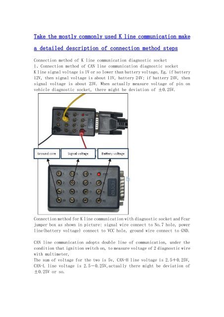
K <strong>line</strong> signal voltage is 1V or so lower than battery voltage, Eg, if battery<br />
12V, <strong>the</strong>n signal voltage is about 11V, battery 24V; if battery 24V, <strong>the</strong>n<br />
signal voltage is about 23V. When actually measure voltage <strong>of</strong> pin on<br />
vehicle diagnostic socket, <strong>the</strong>re might be deviation <strong>of</strong> ±0.25V.<br />
Connection <strong>method</strong> for K <strong>line</strong> <strong>communication</strong> with diagnostic socket and Fcar<br />
jumper box as shown in picture: signal wire connect to No.7 hole, power<br />
<strong>line</strong>(battery voltage) connect to VCC hole, ground wire connect to GND.<br />
CAN <strong>line</strong> <strong>communication</strong> adopts double <strong>line</strong> <strong>of</strong> <strong>communication</strong>, under <strong>the</strong><br />
condition that ignition switch on, to measure voltage <strong>of</strong> 2 diagnostic wire<br />
with multimeter,<br />
The sum <strong>of</strong> voltage for <strong>the</strong> two is 5v, CAN-H <strong>line</strong> voltage is 2.5+0.25V,<br />
CAN-L <strong>line</strong> voltage is 2.5-0.25V,actually <strong>the</strong>re might be deviation <strong>of</strong><br />
±0.25V or so.
Connection <strong>method</strong> for K <strong>line</strong> <strong>communication</strong> with diagnostic socket and Fcar<br />
jumper box as shown in picture<br />
CAN-H connect to No.6 hole, CAN-L connect to No.14 hole, power<br />
<strong>line</strong>(battery voltage)connect to VCC hole, ground wire connect to GND.<br />
Note: When actually measure voltage <strong>of</strong> pin on vehicle diagnostic socket,<br />
<strong>the</strong>re might be deviation <strong>of</strong> ±0.25V.<br />
Connect jumper box with main testing cable, and lock fastening bolts,<br />
as shown in left picture.<br />
15 jumper <strong>connection</strong> holes with numbers marked beside will be seen on<br />
jumper box, <strong>the</strong> corresponding numbers to <strong>the</strong>se <strong>connection</strong> holes is node<br />
relation <strong>of</strong> standard OBD-II port.<br />
Base on diagnostic socket information <strong>of</strong> vehicle, connect diagnostic<br />
interface <strong>of</strong> jumper box.<br />
After <strong>connection</strong>, turn on ignition switch to ON, at this time power<br />
indicator light on jumper box shall be on. Press switch <strong>of</strong> F3-D main<br />
unit,F3-D main unit work properly, appropriate system can be selected for<br />
diagnosis.<br />
Note: If lack <strong>of</strong> knowledge about vehicle electrical equipment or cannot<br />
confirm power supply to electrical equipment, please don’t perform<br />
jumper operation, for error jumper operation will lead to vehicle<br />
electrical equipment or Fcar main unit and cable malfunction.
Vehicle diagnostic equipment socket related information confirm and<br />
tools:<br />
( 1 )、 Digital high impedance multimeter(must use high impedance<br />
multimeter, o<strong>the</strong>rwise will cause damage to computer board)<br />
(2)、When ignition switch to ON, diagnostic socket has supply voltage<br />
from vehicle, <strong>the</strong> voltage difference between voltage on diagnostic socket<br />
and that <strong>of</strong> vehicle battery end cannot be above 2.5V.<br />
(3)、If signal <strong>line</strong> <strong>used</strong> in diagnosis is signal wire <strong>communication</strong> (K<br />
<strong>line</strong>),voltage on signal <strong>line</strong> is 1V lower than battery voltage(if vehicle<br />
supply voltage is 12V,<strong>the</strong>n voltage <strong>of</strong> signal wire is 11V±0.25V; if 24V<br />
supply, voltage <strong>of</strong> signal <strong>line</strong> is23V±0.25V).<br />
(4)、If <strong>the</strong> <strong>communication</strong> <strong>of</strong> duel signal <strong>line</strong> adopts CAN <strong>communication</strong>,<br />
under <strong>the</strong> condition that two diagnostic <strong>line</strong>s in ignition switch on, to<br />
measure voltage <strong>of</strong> ground wire. The sum voltage is 5V, CAN-H <strong>line</strong> voltage<br />
is 2.5V+0.25V,CAN-L <strong>line</strong> voltage is 2.5V-0.25V, actually <strong>the</strong>re may have<br />
deviation <strong>of</strong> ±0.25V or so.