Wagner 505 manual - Spray Tech Systems Inc.
Wagner 505 manual - Spray Tech Systems Inc.
Wagner 505 manual - Spray Tech Systems Inc.

You also want an ePaper? Increase the reach of your titles
YUMPU automatically turns print PDFs into web optimized ePapers that Google loves.
R<br />
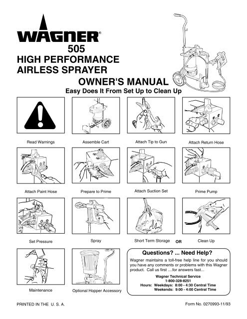
<strong>505</strong><br />
HIGH PERFORMANCE<br />
AIRLESS SPRAYER<br />
OWNER'S MANUAL<br />
Easy Does It From Set Up to Clean Up<br />
Read Warnings Assemble Cart Attach Tip to Gun Attach Return Hose<br />
Attach Paint Hose<br />
Prepare to Prime Attach Suction Set Prime Pump<br />
Set Pressure<br />
<strong>Spray</strong> Short Term Storage OR Clean Up<br />
Maintenance<br />
Optional Hopper Accessory<br />
Questions? ... Need Help?<br />
<strong>Wagner</strong> maintains a toll-free help line for you should<br />
you have any comments or problems with this <strong>Wagner</strong><br />
product. Call us first ....for answers fast...<br />
<strong>Wagner</strong> <strong>Tech</strong>nical Service<br />
1-800-328-8251<br />
Hours: Weekdays: 8:00 - 4:30 Central Time<br />
Weekends: 9:00 - 4:00 Central Time<br />
PRINTED IN THE U. S. A.<br />
1<br />
Form No. 0270993-11/93
General Description ....................................................... 2<br />
Safety Precautions ......................................................3-6<br />
Extension Cord............................................................... 7<br />
Grounding Instructions ................................................... 7<br />
Pressure Relief Procedure ............................................. 8<br />
Set Up .......................................................................9-11<br />
Priming .................................................................... 12-14<br />
<strong>Spray</strong>ing .................................................................. 15-18<br />
CONTENTS<br />
Components:<br />
The shipping carton for your <strong>505</strong> Painting System contains the following components:<br />
Cart frame with wheels, motor and pump attached.<br />
Cart handle<br />
Pail bracket/cart foot<br />
Suction set and return tube<br />
<strong>Spray</strong> gun and filter<br />
<strong>Spray</strong> tip and gasket<br />
Three bolts, washers and wing nuts<br />
25-foot 3/16-inch higher pressure hose<br />
Short Term Storage...................................................... 19<br />
Cleanup and Long Term Shutdown ........................ 20-22<br />
Maintenance........................................................... 23, 24<br />
Optional Hopper ........................................................... 25<br />
Trouble Shooting .................................................... 26, 27<br />
Parts Lists ............................................................... 28-30<br />
Accessories List ........................................................... 31<br />
Warranty........................................................ Back Cover<br />
Spare Outlet Spring, P/N 0047485<br />
Spare Tip Seal , P/N 0156713<br />
Return tube fitting , P/N 0088715<br />
Operator’s <strong>manual</strong><br />
ARE LOCATED IN THE<br />
LITERATURE SET WITH<br />
REGISTRATION CARD<br />
General Description<br />
The <strong>Wagner</strong> <strong>505</strong> High Performance Airless <strong>Spray</strong>er is a<br />
precision power tool used for spraying many types of<br />
materials. It is a relatively simple machine to operate,<br />
however, a basic understanding of its components is<br />
necessary.<br />
Read and follow this instruction <strong>manual</strong> carefully for proper<br />
operating instructions, maintenance and safety<br />
information.<br />
Specifications<br />
Weight: ................................................... 27 lbs. (12 kg )<br />
Capacity: ...............................................Up to 1/3 gallon<br />
(1-1/4 liters) per minute<br />
Power Source: ............................ 1/3 HP Electric Motor,<br />
totally enclosed, fan cooled.<br />
Power Requirement: ......................... 15 amp minimum<br />
circuit on 115 VAC, 60 HZ current.<br />
Generator – 15 amp A/C.<br />
<strong>Spray</strong>ing Pressure: ..............................Up to 2,500 psi.<br />
Safety Features: .................. <strong>Spray</strong> gun safety lock and<br />
pressure diffuser; built-in tip safety<br />
guard; priming knob for safe<br />
pressure release.<br />
Portability:........................ Compact design, light weight<br />
for easy movement.<br />
Capability: ............................ <strong>Spray</strong>s a variety of paints,<br />
oil base, latex, primers, stains,<br />
preservatives and other nonabrasive<br />
materials, including pesticides and<br />
liquid fertilizers.<br />
Pressure Control<br />
Knob<br />
Hydraulic Pump<br />
Priming Knob<br />
Paint Block Suction Set<br />
Paint Hose<br />
On/Off Switch<br />
<strong>Spray</strong> Gun<br />
Figure 1 – <strong>Wagner</strong> <strong>505</strong> Airless <strong>Spray</strong>er<br />
2
SAFETY PRECAUTIONS<br />
This <strong>manual</strong> contains information which must be read and understood before using the equipment. When you come to an<br />
area which has one of the following symbols, pay particular attention and make certain to heed the safeguard.<br />
WARNING<br />
Important safety information indicates a hazard which may cause serious injury or loss of life.<br />
CAUTION<br />
Important information that tells how to prevent damage to equipment or how to avoid causes of minor injuries.<br />
Notes: Gives important information which should be given special attention.<br />
CAUTION<br />
THIS UNIT IS PROVIDED WITH A THERMALLY PROTECTED AUTOMATIC RESET. IF AN OVERLOAD<br />
OCCURS THE THERMALLY PROTECTED AUTOMATIC RESET DISCONNECTS THE MOTOR FROM THE<br />
POWER SUPPLY.<br />
• Motor will restart without warning when protector automatically resets.<br />
• Always disconnect motor from power supply before working on equipment.<br />
• When thermally protected automatic reset disconnects the motor from the power supply, relieve pressure by<br />
turning priming valve to "prime" A .<br />
• Turn ON-OFF switch OFF.<br />
CAUTION: THE CAUSE OF THE OVERLOAD SHOULD BE CORRECTED BEFORE RESTARTING. (SEE<br />
TROUBLE SHOOTING )<br />
3
WARNING<br />
HAZARD<br />
Injection Injury - A high pressure stream of paint produced<br />
by this equipment can pierce the skin and<br />
underlying tissues, leading to serious injury and possible<br />
amputation.<br />
PREVENTION<br />
• Maximum operating range of the gun - 2500 PSI fluid<br />
pressure.<br />
• NEVER aim the gun at any part of the body.<br />
• NEVER allow any part of the body to come in contact<br />
with the fluid stream. DO NOT come in contact with a fluid<br />
stream created by a leak in the fluid hose.<br />
• NEVER put hand in front of the gun. Gloves will NOT<br />
provide protection against an injection injury.<br />
• ALWAYS lock the gun trigger,shut fluid pump off and<br />
release all pressure before servicing, cleaning tip guard,<br />
changing tips, or leaving unattended. Simply turning off<br />
the electrical power will not release pressure in the<br />
system. The Prime <strong>Spray</strong> Valve must be turned to the<br />
prime A position to relieve the pressure.<br />
• ALWAYS have the tip guard in place while spraying. The<br />
tip guard provides some protection against injection<br />
injuries but is mainly a warning device.<br />
DO NOT TREAT AS A SIMPLE CUT! Injectioncan<br />
lead to amputation. See a physician immediately.<br />
NOTE TO PHYSICIAN: Injection into the skin<br />
is a traumatic injury. It is important to treat the<br />
injury surgically as soon as possible. DO<br />
NOT delay treatment to research toxicity.<br />
Toxicity is a concern with some coatings<br />
injected directly into the blood stream. Consultation<br />
with a plastic surgeon or reconstructive<br />
hand surgeon may be advisable.<br />
• ALWAYS remove spray tip before flushing or cleaning<br />
the system. Refer to Cleaning Instructions.<br />
• Paint hose can develop leaks from wear, kinking, abuse<br />
etc. A leak is capable of injecting material into the skin.<br />
The paint hose should be inspected before each use.<br />
• NEVER use a spray gun which does not have a trigger<br />
lock and trigger guard in place and in working order.<br />
• All accessories must be rated at or above 2500 P.S.I.<br />
(<strong>Inc</strong>ludes spray tips, guns, extensions, and hose).<br />
• In case of skin injection see physician immediately.<br />
4
WARNING<br />
HAZARD<br />
Explosion or fire - Solvent and paint fumes can explode or<br />
ignite, causing property damage and or severe injury.<br />
PREVENTION<br />
• Exhaust and fresh air introduction must be provided to<br />
keep the air within the spray area free from accumulation<br />
of flammable vapors.<br />
• Avoid all ignition sources such as static electricity sparks,<br />
open flames such as pilot lights, hot objects such as<br />
cigarettes, and sparks from connecting and disconnecting<br />
power cords and working light switches.<br />
• Fire extinguishing equipment must be present and in<br />
working order.<br />
• Keep the pump away from spray area to avoid solvent<br />
and paint fumes. The pump contains arcing parts which<br />
emit sparks.<br />
• Do not spray paints and other inflammable fluids which<br />
have a flashpoint below 21° C (70° F). (Flashpoint is the<br />
temperature at which a fluid begins giving off a sufficient<br />
amount of flammable vapor that could ignite when exposed<br />
to a flame or spark.)<br />
• High velocity flow of material through equipment may<br />
develop static electricity. The equipment being used, and<br />
objects in and around the spray area must be properly<br />
grounded to prevent static discharge and sparks.<br />
• Use only conductive or grounded high pressure fluid<br />
hoses for airless applications. Be sure that gun is grounded<br />
through hose connections.<br />
• Power cord must be connected to a grounded circuit.<br />
(See proper grounding instructions.)<br />
• Follow the material and solvent manufacturer's safety<br />
precautions and warnings.<br />
• WHEN FLUSHING EQUIPMENT use lowest possible<br />
pressure.<br />
5
WARNING<br />
HAZARD<br />
Explosion hazard incompatible materials - May cause<br />
property damage or severe injury.<br />
PREVENTION<br />
• DO NOT USE BLEACH.<br />
• DO NOT use halogenated hydrocarbon solvents.<br />
• Halogenated hydrocarbon solvents such as methylene<br />
chloride and 1,1,1 - Trichlorethane are not compatible<br />
with aluminum and may cause an explosion. If unsure of<br />
a material’s compatibility with aluminum, contact your<br />
coatings supplier.<br />
Hazardous vapors - Paints, solvents, insecticides, and<br />
other materials may be harmful if inhaled causing severe<br />
nausea, fainting, or poisoning.<br />
• Use a respirator or mask whenever there is a chance that<br />
vapors may be inhaled. Read all instructions with the<br />
mask to insure that it will provide the necessary protection<br />
against the inhalation of harmful vapors.<br />
General - May cause property damage or severe injury.<br />
• Read all instructions and safety precautions before operating.<br />
• Comply with all appropriate local, state and national<br />
codes governing ventilation, fire prevention, and operation.<br />
• The United States Government Safety Standards have<br />
been adopted under Occupational Safety and Health Act.<br />
These standards, particularly the General Standards,<br />
Part 1910 and construction Standard, Part 1926, should<br />
be consulted.<br />
• This high pressure airless pump is designed to be used<br />
with authorized parts only. When using this pump with<br />
parts that do not comply with the minimum specifications<br />
and safety devices of the pump manufacturer, the user<br />
assumes all risks and liabilities.<br />
• Before each use, check all hoses for cuts, leaks, abrasion<br />
or bulging of cover or damage or movement of couplings.<br />
If any of these conditions exist, replace the hose immediately.<br />
Never repair a paint hose. Replace it with another<br />
grounded hose.<br />
• All hoses, swivels, guns, and accessories used with this<br />
unit must be pressure rated at or above 2500 PSI.<br />
• DO NOT spray on windy days.<br />
6
Extension Cord<br />
Use only a 3-wire extension cord that has a 3-blade<br />
grounding plug and a 3-slot receptacle that will accept the<br />
plug on the product. Make sure your extension cord is in<br />
good condition. When using an extension cord, be sure to<br />
use one heavy enough to carry the current your product will<br />
draw. An undersized cord will cause a drop in line voltage<br />
resulting in loss of power and overheating. A 14 or 12<br />
gauge cord is recommended.<br />
NOTE: More than 100 feet of extension cord is not<br />
recommended. Use more paint hose, not more<br />
extension cord. Shorter extension cords will assure<br />
maximum electrical power for proper operation.<br />
Grounding Instructions<br />
This product is for use on a nominal 120 volt circuit, and has<br />
a grounding plug that looks like plug illustrated in Figure 2<br />
(A) below. A temporary adapter which looks like the adapter<br />
illustrated in Figure 2 (B) and (C), may be used to connect<br />
this plug to a 2 pole receptacle as shown in Figure 2 (B) if<br />
a properly grounded outlet is not available. The temporary<br />
adapter should be used only until a properly grounded<br />
outlet as shown in Figure 2 (A) can be installed by a<br />
qualified electrician. The green colored rigid ear lug, or the<br />
like extending from the adapter must be connected to a<br />
permanent ground such as a properly grounded outlet box<br />
cover. Whenever the adapter is used, it must be held in<br />
place by a metal screw.<br />
Grounded<br />
Outlet<br />
This product must be grounded. In the event of an electrical<br />
short circuit, grounding reduces the risk of electric shock by<br />
providing an escape wire for the electric current. This<br />
product is equipped with a cord having a grounding wire<br />
with an appropriate grounding plug. The plug must be<br />
plugged into an outlet that is properly installed and grounded<br />
in accordance with all local codes and ordinances.<br />
WARNING<br />
Improper installation of the<br />
grounding plug can result in a<br />
risk of electric shock.<br />
Metal<br />
Screw<br />
Grounding Pin<br />
(A)<br />
Cover of Grounded Outlet Box<br />
Adapter<br />
(C)<br />
If repair or replacement of the cord or plug is necessary, do<br />
not connect the green grounding wire to either flat blade<br />
terminal. The wire with insulation having an outer surface<br />
that is green with or without yellow stripes is the grounding<br />
wire and must be connected to grounding pin.<br />
Check with a qualified electrician or serviceman if the<br />
grounding instructions are not completely understood, or if<br />
in doubt as to whether the product is properly grounded. Do<br />
not modify the plug provided; if it will not fit the outlet, have<br />
the proper outlet installed by a qualified electrician.<br />
(B)<br />
Tab for<br />
Grounding Screw<br />
Figure 2 – Grounding Methods<br />
7
Pressure Relief Procedure<br />
Follow this procedure after the unit is assembled and before any operation which involves the spray gun such as<br />
changing tips or accessories, or cleaning and maintenance.<br />
1. Make sure PRESSURE CONTROL KNOB is at its lowest<br />
setting (counterclockwise).<br />
3. Trigger gun to remove any pressure which may still be<br />
in the hose.<br />
Pressure Control<br />
Knob<br />
2. Turn PRIMING KNOB to PRIME A position.<br />
4. Lock gun trigger in the Off position.<br />
Prime A<br />
<strong>Spray</strong> B<br />
Knob<br />
Trigger Lock<br />
Injection hazard possible. Do<br />
WARNING not spray without tip guard in<br />
place. NEVER trigger gun unless tip is completely turned<br />
to the spray or unclog position. ALWAYS engage trigger<br />
lock before removing, replacing or cleaning tip.<br />
8
SET-UP<br />
ASSEMBLE CART<br />
Tools needed:<br />
Some assembly is required to get your <strong>Wagner</strong> <strong>505</strong><br />
Airless <strong>Spray</strong>er ready to go. You will need two adjustable<br />
wrenches, a screw driver and a pair of pliers.<br />
Pail Bracket<br />
NOTE: <strong>Spray</strong>er should remain unplugged during<br />
assembly.<br />
1. Slide pail bracket (1) onto cart frame and attach with<br />
one bolt, washer and wing nut (2). See Figure 2 and<br />
Figure 3 A. This bracket helps to keep the sprayer<br />
stable in addition to providing a rest for the paint<br />
bucket and a catch for the bucket handle.<br />
Bolt, washer<br />
and wing nut<br />
Figure 3A - Attaching Pail Bracket<br />
4<br />
3<br />
2. Attach cart handle (3). Face the hose hook toward the<br />
front of the unit. Use two bolts, washers and wing nuts<br />
(4), tightening securely. See Figure 3B.<br />
Cart Handle<br />
2<br />
Bolt, washer<br />
and wing nut<br />
1<br />
Figure 2 – Cart Assembly Diagram<br />
Figure 3B - Attaching Cart Handle<br />
9
SET-UP<br />
ATTACH TIP TO GUN<br />
1. Lock gun. See Figure 4.<br />
Locked<br />
Position<br />
Unlocked<br />
Position<br />
3. Check seal alignment by removing tip and inspecting<br />
tip guard visually, See Figure 6. If needed, remove<br />
seal (3) and replace until properly aligned. Replace<br />
tip to spray position, (arrow away from gun). Insert<br />
red seal (4).<br />
Figure 4 - Gun in Locked & Unlocked Position<br />
2. If spray tip is not pre- assembled, (See Figure 5)<br />
insert tip (1) into tip guard, (2) and turn 90° counterclockwise<br />
to spray position (arrow pointing away<br />
from gun). Cylinder of tip forms a stop for the seal (3).<br />
Insert seal (3) aligning the curve of the seal with the<br />
curve of the tip.<br />
Correct Way<br />
Figure 6 - <strong>Spray</strong> Tip Assembly<br />
Wrong Way<br />
4. Attach spray tip to gun. Tighten nut first by hand,<br />
then tighten with a wrench. See Figure 7.<br />
3<br />
4<br />
2<br />
1<br />
Red Seal<br />
Figure 7- Attach Tip to Gun<br />
Figure 5 – <strong>Spray</strong> Tip Assembly<br />
NOTE: When attaching tip to gun, align tip guard as<br />
shown in Figure 8. Then tighten with wrench.<br />
WARNING<br />
POSSIBLE INJECTION<br />
HAZARD. Do not spray without<br />
tip guard in place. Never trigger gun unless tip is in<br />
the spray or unclog position. Always engage trigger lock<br />
before removing, replacing or cleaning tip.<br />
Figure 8 - Vertical Tip Pattern<br />
10
SET-UP<br />
ATTACH RETURN HOSE<br />
ATTACH PAINT HOSE<br />
1. Be sure motor switch is turned OFF.<br />
2. Screw brass fitting of return tube into upper port on<br />
side of pump. (The brass fitting is located in the<br />
literature set.) Tighten firmly by hand. See figure<br />
above.<br />
3. Press return tube (small tube) to brass fitting and<br />
fasten with clamp. See Figure 9.<br />
1. Attach high pressure hose to hose port, using an<br />
adjustable wrench to tighten firmly. (See illustration<br />
above.)<br />
2. Attach gun to other end of high pressure hose.<br />
Tighten securely with two adjustable wrenches. See<br />
Figure 10.<br />
Figure 10 - Attaching High Pressure Hose to Gun.<br />
Figure 9 - Fastening Return Tube with Clamp<br />
3. Plug unit into a properly grounded outlet or heavy<br />
duty grounded extension cord. Do not use more<br />
than 100 feet of cord. If you must spray a long<br />
distance from a power source, use more paint hose,<br />
not more extension cords. Use a minimum size of 16<br />
gauge electric cord for 50 feet; 12-14 gauge for 100<br />
feet.<br />
11
PRIMING<br />
PREPARE TO PRIME<br />
1. Lay unit back on its handle so inlet valve is facing up.<br />
Fill inlet valve with water or light household oil.<br />
2. Make sure Prime/<strong>Spray</strong> Knob is in Prime A position<br />
and Pressure Knob is turned to the lowest pressure.<br />
(Counter clockwise) See Figure 11. Turn unit on.<br />
4. Force the inlet valve to open and close by pushing on<br />
it with the eraser end of a pencil or screwdriver, it<br />
should move up and down about 1/16 inch. Continue<br />
until water or oil is sucked into unit. This will assist in<br />
wetting the moving parts and breaking loose any old<br />
paint residue. See Figure 13.<br />
Inlet Valve Facing Up<br />
PrimeA /<strong>Spray</strong> B<br />
Knob<br />
Hose Port<br />
Figure 11 - Prime/<strong>Spray</strong> Knob<br />
3. <strong>Inc</strong>rease pressure half turn.<br />
Figure 13 - Opening Inlet Valve<br />
5. Put palm of hand over inlet valve and feel for a slight<br />
suction while increasing the pressure control to the<br />
maximum setting. See Figure 14. If suction is felt go<br />
to step 6. If no suction is felt see Cleaning and<br />
Servicing Outlet Valve. ( Repeat steps 1 through 5 if<br />
necessary.)<br />
Pressure Control<br />
Knob<br />
Figure 14 - Checking for Suction<br />
Figure 12 - Pressure Control Knob<br />
6. Turn Pressure Control Knob to minimum pressure<br />
and shut off unit.<br />
7. Return unit to upright position.<br />
12
ATTACH SUCTION SET<br />
PRIMING<br />
PRIME THE PUMP<br />
1. Attach Suction Tube to inlet valve and tighten firmly<br />
by hand. See Figure 15. Be sure threads are straight<br />
so the fitting turns freely without binding.<br />
(Do Not<br />
cross thread)<br />
1. Make sure the PRESSURE CONTROL KNOB is at<br />
its lowest setting (counterclockwise). See Figure<br />
18.<br />
Pressure Control<br />
Knob<br />
Figure 15 - Attaching Suction Tube<br />
2. Place suction tube and return tube in paint. See<br />
Figure 16.<br />
Figure 18 - Set Pressure Control Knob<br />
2. Turn PRIMING KNOB to Prime A position. See<br />
Figure 19.<br />
Figure 16 - Place Suction Tube and Return Tube in<br />
Paint.<br />
3. Set paint bucket onto pail bracket and attach<br />
handle. See Figure 17.<br />
Prime A<br />
<strong>Spray</strong> B<br />
Knob<br />
Figure 19 - Priming Knob Setting<br />
Figure 17 - Attaching Paint Pail Handle<br />
13<br />
13
PRIMING<br />
PRIME THE PUMP<br />
Continued from page 13<br />
3. TURN SPRAYER ON.<br />
4. Turn PRESSURE CONTROL KNOB between half<br />
and full pressure. See Figure 20. You should then<br />
be able to see the paint move through the suction<br />
tube to the pump. Continue until paint flows through<br />
the return tube. (Let unit prime 1 to 2 minutes).<br />
Always reduce pressure to zero<br />
CAUTION before changing the position of<br />
the priming knob. Failure to do so may cause damage to<br />
the paint pump diaphragm.<br />
If the Pressure Control Knob is<br />
CAUTION reduced to zero and the Priming<br />
Knob is still on spray during sprayer operation, there will<br />
be high pressure in the hose and spray gun until the<br />
Priming Knob is turned to PRIME A or until the spray gun<br />
is triggered to relieve the pressure.<br />
Figure 20 - Turn Pressure Control Knob<br />
14
SPRAYING<br />
PRACTICE FIRST<br />
1. Be sure paint hose is free of kinks and clear of traffic<br />
or objects with sharp cutting edges.<br />
2. Return PRESSURE CONTROL KNOB to its lowest<br />
setting (counterclockwise). Figure 21.<br />
Figure 23 - Practice on scrap material.<br />
Figure 21 - Pressure Control Knob Setting<br />
3. Turn PRIMING KNOB to SPRAY B position. Figure<br />
22.<br />
5. Unlock SPRAY GUN TRIGGER LOCK by turning lock<br />
down toward the bottom of the handle. Figure 4<br />
6. Trigger spray gun to bleed air out of hose.<br />
7. When paint reaches spray tip, spray a test area to<br />
check spray pattern. See Figure 23.<br />
8. Use the lowest pressure setting necessary to get a<br />
good spray pattern. If pressure is too high, material is<br />
over-atomized. If pressure is too low, tailing will<br />
appear or paint will spatter out in gobs rather than in<br />
a fine spray. See Figure 24. Most latex paints and<br />
stains will require very high pressure, which is why the<br />
sprayer is built to deliver up to 2,500 psi when needed.<br />
PrimeA<br />
<strong>Spray</strong> B<br />
Knob<br />
GOOD SPRAY PATTERN<br />
Figure 22 - Priming Knob Setting<br />
4. Turn PRESSURE CONTROL KNOB completely<br />
clockwise to maximum pressure, Figure 21. Paint<br />
should then begin to flow into the paint hose, causing<br />
it to stiffen.<br />
Figure 24 - Paint Tailing Pattern<br />
15
SPRAYING<br />
SPRAYING TECHNIQUE<br />
1. The key to a good paint job is an even coating over the<br />
entire surface. With spray painting, this is done by<br />
using even strokes, with your arm moving at a constant<br />
speed and keeping the spray gun a constant<br />
distance from the surface.<br />
Even Coat on Work Throughout<br />
Approximately<br />
Approximatley<br />
10 10 to to 12 12 <strong>Inc</strong>hes<br />
2. In most cases, the best spraying distance is 10 to 12<br />
inches between the spray tip and the surface.<br />
3. As much as possible, keep the spray gun at right<br />
angles to the surface. This means moving your entire<br />
arm back and forth rather than just flexing your wrist.<br />
See Figures 25 and 26.<br />
Right<br />
Way To <strong>Spray</strong><br />
Steady Arm<br />
4. Keep the spray gun perpendicular to the surface,<br />
otherwise one end of the pattern will be thicker than<br />
the other. See Figure 27.<br />
Figure 26 - Result of smooth arm stroke and steady,<br />
even speed while spraying.<br />
Approximately<br />
10 to 12 <strong>Inc</strong>hes<br />
Right Way<br />
Wrong Way<br />
Figure 25 - Result of Flexing Wrist While <strong>Spray</strong>ing<br />
Figure 27 - Right and wrong ways to hold spray gun<br />
toward work.<br />
16
SPRAYING<br />
5. The spray gun should be triggered off at the end of<br />
each stroke and on again at the beginning of the next.<br />
This avoids paint buildup at the end of the stroke<br />
which may result in runs and sags. Triggering at the<br />
end of the stroke also saves paint and results in a<br />
better looking job. See Figure 28.<br />
Start<br />
Stroke<br />
Pull<br />
Trigger<br />
Approximatley<br />
Approximately<br />
10 to 12 <strong>Inc</strong>hes<br />
Work<br />
Even Steady<br />
Stroke<br />
Release<br />
Trigger<br />
End<br />
Stroke<br />
If <strong>Spray</strong> Tip Becomes Clogged<br />
The spray gun is equipped with a reversible tip which<br />
enables you to quickly and effectively blow out any particles<br />
of old paint or other contaminants that may obstruct the<br />
paint flow through the tip. If the spray pattern becomes<br />
distorted or stops completely while the gun is triggered on,<br />
follow these steps.<br />
1. Release the trigger and put on the safety lock. See<br />
Figure 4.<br />
2. Rotate the reversible tip cylinder arrow 180° so the<br />
point of the arrow is toward the rear of the gun. Figure<br />
29.<br />
Figure 28 - Proper Way to Trigger <strong>Spray</strong> Gun<br />
6. Overlap each stroke by about 30%. This will assure<br />
a paint coating that is uniform across the work. One<br />
way to do this is to point the spray tip at the edge of<br />
the last stroke before triggering the gun on.<br />
7. When taking a short break from painting (up to 1 hr.),<br />
lock the spray gun trigger OFF, reduce pressure to its<br />
minimum (zero) setting and set the unit to prime A .<br />
Turn sprayer off and unplug. Refer to Pressure<br />
Relief Procedure.<br />
8. If you expect to be gone more than 1 hour follow the<br />
short term clean up procedure.<br />
Figure 29 - Reverse Tip<br />
3. Unlock the trigger and squeeze it open, pointing the<br />
gun at a scrap piece of wood or cardboard. This allows<br />
pressure in the paint hose to blow out the obstruction.<br />
When the nozzle is clean, paint will come out in a<br />
straight, high pressure stream.<br />
4. Release the trigger and re-lock it. Figure 4<br />
5. Reverse the tip so the arrow points forward again.<br />
6. Unlock the trigger and resume spraying.<br />
17
Continued from page 17<br />
SPRAYING<br />
Cleaning The <strong>Spray</strong> Gun Filter<br />
The spray gun includes a filter to catch particles before<br />
they reach the spray tip. If this filter becomes clogged or<br />
obstructed it will reduce the flow of paint, changing the<br />
spray pattern and possibly damaging the filter.<br />
This filter must be cleaned at least daily and perhaps<br />
even every four hours with certain types of latex<br />
materials.<br />
6. Insert the top of the filter (Figure 30) into the gun body<br />
fitting under the tip of the spray gun. See Figure 31.<br />
Spring<br />
If the filter is not cleaned at the proper time, it will plug from<br />
the top down. When there is about 1 inch of filter that isn't<br />
plugged, the heavy flow of paint will blow pin holes in the<br />
filter. See Figure 30. This in turn will allow unwanted<br />
particles to get into the spray tip, causing spray tip to clog.<br />
Gun Body Fitting<br />
Filter<br />
Sealing Washer<br />
Filter Housing<br />
Top of Filter<br />
Figure 31 - Gun Filter Cleaning.<br />
7. Replace the spring and sealing washer into the base<br />
of the filter housing.<br />
Pin Hole<br />
Figure 30 - Gun Filter Cleaning.<br />
To clean the filter during the painting process:<br />
1. Turn spray PRESSURE CONTROL KNOB to minimum<br />
setting and turn PRIMING KNOB to PRIME A .<br />
This will bleed off the pressure in the paint hose and<br />
filter. Trigger gun to be sure pressure is gone. Refer<br />
to Pressure Relief Procedure.<br />
2. Remove spray gun from hose using two adjustable<br />
wrenches. See Figure 10<br />
3. Unscrew filter housing, using adjustable wrench on<br />
the nut at the bottom of the housing.<br />
4. Remove filter being sure not to lose the spring and<br />
sealing washer which is located in the bottom of the<br />
filter housing.<br />
5. Clean filter thoroughly (or put in a new filter). To clean<br />
the filter, swish it in water or the type of solvent<br />
appropriate to the paint you are using. If this isn’t<br />
sufficient, use a natural or nylon bristle brush dipped<br />
in the appropriate solvent or water. Do not use a wire<br />
brush or any sharp instrument.<br />
8. Slide the filter housing over the filter and tighten it<br />
securely to the gun, using a wrench.<br />
9. Reattach the hose, tightening it securely with two<br />
wrenches.<br />
10. Turn PRIMING KNOB to SPRAY B , (Figure 10)<br />
increase pressure to its previous setting and resume<br />
spraying.<br />
Suction Set Screen<br />
The screen at the bottom of the suction set may also need<br />
cleaning periodically. Check it every time you change<br />
paint buckets. Remove screen by pulling it out of the<br />
retainer with a pliers. Clean the screen with water or<br />
solvent and a soft-bristle brush, if needed.<br />
Figure 32 - Remove And Clean Screen<br />
18
CLEAN UP<br />
SHORT-TERM/OVERNIGHT STORAGE<br />
Shut-down<br />
1. Lock the gun and reduce the pressure. Turn the<br />
sprayer to prime A and shut it off. Unplug sprayer.<br />
Leave the suction set in the paint. Refer to Pressure<br />
Relief Procedure.<br />
2. For latex materials only, pour 1/2 cup water slowly<br />
on the top of the paint to prevent the paint from drying.<br />
For other materials, seal the paint container with a<br />
piece of plastic while the suction tube is still in the<br />
paint. See Figure 33.<br />
Start-up<br />
1. Remove the gun from the plastic bag.<br />
2. Stir the water into the paint for latex materials. Remove<br />
the seal from the paint bucket and stir the paint<br />
for all other materials.<br />
– OR –<br />
Figure 35 - Stir Material Before <strong>Spray</strong>ing<br />
Figure 33 – Add 1/2 Cup Water to Latex Paint<br />
Seal Container for Other Materials.<br />
3. Wrap the spray gun (completely assembled) in a<br />
damp cloth and place it in a plastic bag. Seal the bag<br />
shut. See Figure 34.<br />
3. Check to be sure the sprayer is in the Prime A<br />
position with the pressure completely reduced.<br />
4. Plug sprayer in and turn on.<br />
5. Turn the sprayer to <strong>Spray</strong> B and gradually increase<br />
the pressure.<br />
6. Test the sprayer on a practice piece and begin<br />
spraying.<br />
Figure 34 - Place Gun in Sealed Bag<br />
4. Place the sprayer in a safe place out of the sun for<br />
short-term storage.<br />
Figure 36 - Test on scrap material.<br />
19
CLEANUP<br />
SHUT DOWN/CLEAN UP<br />
WARNING<br />
Do not allow paint to build up on<br />
the motor. Overheating of the<br />
motor will result. Do not allow flammable solvents to<br />
come in contact with the motor, which could ignite.<br />
NOTE: You will need an extra bucket with cleaning<br />
solution, a toothbrush, an adjustable wrench and<br />
rags.<br />
1. Lock the gun and reduce the pressure. Turn the<br />
sprayer to prime A and shut it off. Unplug sprayer.<br />
Leave the suction set in the paint. Refer to Pressure<br />
Relief Procedure.<br />
2. Remove suction tube from paint and hold it above a<br />
bucket of water or solvent. Leave the return tube<br />
aimed into the paint bucket.<br />
3. If spraying with latex paint, use warm soapy water for<br />
cleaning. If using oil or alkyd-based paints, use<br />
mineral spirits or paint thinner. Do not use these<br />
solvents on latex paint, or the mixture will turn into a<br />
jelly-like substance which is difficult to remove. Plug<br />
the unit in and turn on.<br />
4. <strong>Inc</strong>rease PRESSURE CONTROL KNOB clockwise<br />
to about 1/3 to 1/2 maximum pressure. This will draw<br />
the remaining paint in the suction tube through the<br />
pump and down the return tube into the paint bucket.<br />
5. Set PRESSURE CONTROL KNOB counterclockwise<br />
back to minimum pressure. Trigger gun to<br />
relieve pressure and lock gun.<br />
6. Remove spray tip and guard, washer, and let soak<br />
in warm water or appropriate solvent.<br />
7. Place suction tube and return tube in container of<br />
water or compatible solvent.<br />
8. <strong>Inc</strong>rease pressure to about 1/2 maximum pressure<br />
and let circulate for 2-3 minutes to flush paint out of<br />
the pump, suction tube and return tube.<br />
9. To save paint left in the hose, carefully trigger the<br />
gun (with spray tip removed) against the inside of the<br />
paint container. See Figure 37. Reduce PRES-<br />
SURE CONTROL KNOB to zero, then turn PRIM-<br />
ING KNOB to SPRAY B .<br />
Figure 37 - Save Paint Back To Paint Can.<br />
10. <strong>Inc</strong>rease PRESSURE CONTROL KNOB again until<br />
paint starts to flow into the bucket. As soon as the<br />
water or solvent starts to come into the bucket,<br />
release the trigger.<br />
11. Change to clean water or solvent and continue<br />
circulating for another 5 minutes to thoroughly clean<br />
the hose, pump and spray gun.<br />
12. Reduce pressure and turn to prime A . Trigger gun.<br />
Lock gun and shut sprayer off.<br />
13. Remove spray gun from paint hose, using two<br />
adjustable wrenches. Remove filter housing from<br />
gun. Place gun and filter assembly into a container<br />
of water or solvent to soak. Cover paint container<br />
and set it aside.<br />
20
CLEAN UP<br />
14. Clean spray tip and gun filter with a soft brush.<br />
Reassemble spray tip in cleaning position. (Arrow<br />
points to back of the gun.)<br />
16. Turn the unit on and unlock gun trigger. Turn to<br />
<strong>Spray</strong> B and point gun to side of cleaning bucket.<br />
Figure 41 - Cleaning Bucket<br />
17. Trigger gun and gradually turn pressure knob clockwise<br />
to 1/2 pressure. Continue for approximately 30<br />
seconds.<br />
18. Release and lock trigger, reduce pressure, turn to<br />
prime A . Turn unit off.<br />
19. Remove tip assembly. Raise the suction set above<br />
the cleaning solution. Turn unit on, turn to spray B<br />
increase pressure and allow suction tube to run dry.<br />
15. Attach paint hose to gun,tighten with two wrenches.<br />
20. Remove large suction tube from inlet valve, See<br />
Figure 42 and point gun into cleaning bucket, See<br />
Figure 41. Reduce pressure about 1/2, unlock gun,<br />
trigger gun until hose is pumped dry.<br />
Figure 40 - Attach Paint Hose to Gun<br />
Figure 42 - Removing Large Suction Tube<br />
21
CLEAN UP<br />
21. Lock gun, reduce pressure and turn Prime/<strong>Spray</strong><br />
Knob to prime A .<br />
22. Lay unit back on handle so inlet valve is facing<br />
upward. Clean threads of inlet valve with a damp<br />
cloth. Fill inlet valve with light household oil. See<br />
Figure 43. Slowly increase pressure to distribute the<br />
oil through the pump. Turn Prime/<strong>Spray</strong> Knob from<br />
prime A to spray B to distribute oil. Replace large<br />
suction tube to inlet valve.<br />
23. Turn Prime/<strong>Spray</strong> Knob to prime A , reduce pressure,<br />
shut sprayer off. Unplug sprayer. Refer to<br />
Pressure Relief.<br />
24. Remove and clean suction set filter in clean water or<br />
solvent with soft brush. Reassemble.<br />
Figure 43 - Fill Inlet Valve With Oil<br />
Figure 44 - Remove And Clean Filter<br />
IMPORTANT!<br />
Proper cleaning and oiling of the pump after use<br />
are the most important steps you can take to insure<br />
proper operation after storage.<br />
25. Wipe entire unit, hose and gun with a damp cloth to<br />
remove accumulated paint.<br />
22
MAINTENANCE<br />
CLEANING VALVES<br />
Follow these procedures when encountering<br />
problems indicated in the trouble shooting<br />
section.<br />
Removing and Cleaning Inlet Valve<br />
1. Be sure sprayer is off.<br />
2. Using a 27 millimeter socket or box end wrench,<br />
remove the inlet valve assembly.<br />
Remove<br />
Inlet Valve<br />
NOTE: The inlet valve must be oiled after every job.<br />
This will reduce or eliminate priming problems the next<br />
time the sprayer is used. See Figure 43.<br />
4. Thoroughly clean the valve assembly with solvent<br />
and brush.<br />
5. A properly seated valve filled with water and held<br />
vertically will not drip out the bottom of the valve. If<br />
you have properly cleaned the valve and water drips<br />
out the bottom, the valve is worn and needs to be<br />
replaced.<br />
6. Install cleaned or new valve in the pump block and<br />
then fill the valve with light oil or solvent.<br />
7. If none of the above steps work, see Troubleshooting.<br />
Cleaning and Servicing Outlet Valve<br />
Figure 45- Removing Inlet Valve<br />
3. Test movement of the valve by pushing on it from the<br />
open end of the valve housing with the eraser end of<br />
a pencil or a screwdriver. It should move about 1/16<br />
inch. If it doesn't move, it is probably full of dry paint<br />
or other debris and should be cleaned or replaced.<br />
It may be occasionally necessary to remove and clean the<br />
outlet valve or replace normal wear parts inside the valve.<br />
See Figures 47 and Figure 48.<br />
1. Remove outlet cap with adjustable wrench.<br />
Outlet Valve<br />
Figure 46 - Test Movement of Valve<br />
Figure 47 - Removing Outlet Valve<br />
23
MAINTENANCE<br />
CLEANING VALVES<br />
2. If possible, leave the copper washer under the cap in<br />
place. At least be sure to replace it with the same<br />
side up. (The top will show the imprint of the end cap,<br />
while the bottom should be perfectly flat to match<br />
seat in the pump casting.) See Paint Pump Assembly<br />
Parts Diagram,Item 4 for replacement part number.<br />
A spare outlet<br />
valve spring is included<br />
in the literature<br />
set.<br />
Spring<br />
Seat<br />
Cap<br />
Ball<br />
Seal<br />
3. With a wire hook or tweezers, remove the small<br />
spring inside the valve. Replace if broken, or worn or<br />
clean as necessary. See Paint Pump Assembly<br />
Parts Diagram, Item 4 for replacement part number.<br />
This spring is manufactured to a very specific tension,<br />
so do not put in an unauthorized subsitute.<br />
Proper spring length is 7-1/2 coils.<br />
4. Using a six-millimeter allen wrench, remove the seat<br />
and ball assembly. See Figure 48.<br />
5. Clean parts thoroughly. If the ball or seat show any<br />
sign of wear or damage, replace it with a new one.<br />
This carbide ball must seal tightly against its seat for<br />
the valve to function properly.<br />
6. When reassembling, first cover all parts with a thin<br />
coat of light oil. Tighten the valve seat securely with<br />
the 6-millimeter hexagonal wrench, then drop in the<br />
valve ball. Re-insert the spring and replace the cap,<br />
being sure the copper washer is in place and the<br />
tongue on the cap fits inside the spring. Tighten the<br />
cap securely with an adjustable wrench. Do not<br />
over-tighten.<br />
Figure 48 - Servicing Outlet Valve<br />
NOTE: Wear on the ball is almost impossible to<br />
detect visually. A sure way to test for a worn outlet<br />
valve assembly is to run the sprayer with water only<br />
for 10 to 15 minutes on high pressure in the spray<br />
setting without triggering the gun.<br />
If the valve is defective, the end cap will get very hot<br />
to the touch. If it is functioning properly, it will stay<br />
approximately the same temperature as the water<br />
running through it.<br />
24<br />
Priming Knob Slippage<br />
Sometimes the two allen screws holding the black<br />
plastic PRIMING KNOB outer cover will vibrate loose.<br />
This allows the knob to turn without changing the valve<br />
setting. If this happens, loosen the screw with a 1/16<br />
allen wrench, turn the knob to spray and retighten.
OPTIONAL HOPPER ASSEMBLY<br />
CONVERTING SPRAYER FOR HOPPER OPERATION<br />
The hopper assembly consists of the hopper, hopper<br />
return tube and hopper screen. To make the conversion:<br />
1. Remove suction tube and return tube and brass<br />
return tube fitting from the unit.<br />
2. To convert the cart into its horizontal configuration<br />
as shown in Figure 49, reverse the positions of the<br />
handle and pail bracket.<br />
3. Screw the hopper directly onto the inlet valve where<br />
the suction tube was removed. Make the connection<br />
hand tight, just tight enough to prevent paint leakage<br />
or air suction around the threads.<br />
Hopper<br />
Hopper Return Tube<br />
4. Screw in the plastic return tube fitting into the paint<br />
pump port that the brass fitting was removed from.<br />
Attach hopper return tube to the fitting where the<br />
suction set return tube was removed. The connection<br />
needs to be only hand tight.<br />
5. Fit the hopper screen into the bottom of the hopper,<br />
being sure it is properly seated.<br />
NOTE: The hopper screen is essential to trap<br />
debris and other foreign objects from entering<br />
the pump. Do not operate the sprayer without<br />
the screen properly in place.<br />
Cleaning Hopper Unit<br />
To clean the hopper unit:<br />
1. Flush the pump and hose with water or solvent<br />
following the same procedure as with the suction<br />
tube, being sure the return tube is thoroughly flushed<br />
out.<br />
2. Clean the hopper screen with water or appropriate<br />
solvent. If necessary use a nylon or natural bristle<br />
brush dipped in solvent or soapy water.<br />
3. Wash the hopper thoroughly using soapy water<br />
for latex paint, the appropriate solvent with other<br />
materials.<br />
Figure 49 - Optional Hopper<br />
25
TROUBLE SHOOTING<br />
Problem Cause Remedy<br />
<strong>Spray</strong>er does not start up. <strong>Spray</strong>er not plugged in. Plug in.<br />
ON/OFF switch OFF.<br />
Flip switch to ON.<br />
Blown fuse in circuit.<br />
Replace fuse.<br />
No voltage or low voltage<br />
Test power supply voltage.<br />
at wall plug.<br />
Unit turned off under pressure. Turn Prime/<strong>Spray</strong> Knob to Prime position.<br />
Damaged motor cord or<br />
Replace extension cord.<br />
extension cord, or capacity too low.<br />
Thermal overload tripped<br />
Allow motor to cool,move to a shady spot.<br />
Motor problem.<br />
Take to <strong>Wagner</strong> Authorized Service Center.<br />
<strong>Spray</strong>er starts up but does not<br />
draw in paint. (Make sure prime/<br />
spray knob is in prime position.)<br />
Unit will not prime or has lost<br />
prime.<br />
No paint. Suction tube not<br />
totally immersed in paint.<br />
Suction set filter clogged.<br />
Hopper screen clogged<br />
Suction tube loose at inlet valve.<br />
Inlet valve stuck.<br />
Outlet valve stuck.<br />
Prime spray valve plugged<br />
or dirty.<br />
Inlet valve worn or damaged.<br />
Diaphragm problem.<br />
Hydraulic oil level low or empty.<br />
Reprime Unit.<br />
Immerse suction tube in paint.<br />
Clean filter.<br />
Clean screen.<br />
Clean connection and tighten.<br />
Clean inlet valve.<br />
Clean outlet valve.<br />
Replace any worn parts.<br />
Take to <strong>Wagner</strong> Authorized Service Center.<br />
Clean or replace.<br />
Take to <strong>Wagner</strong> Authorized Service Center.<br />
Take to <strong>Wagner</strong> Authorized Service Center.<br />
<strong>Spray</strong>er draws up paint but<br />
drops away when gun is<br />
opened.<br />
Worn spray tip<br />
Replace with new tip.<br />
Suction set filter clogged.<br />
Clean filter.<br />
Optional hopper screen clogged. Clean screen.<br />
Gun or spray tip filter plugged. Clean or replace filter. Keep extra filters<br />
on hand.<br />
Paint too heavy or coarse.<br />
Thin or strain paint.<br />
Dirty or worn outlet valve assembly. Clean or replace.<br />
Inlet valve worn or damaged. Replace valve.<br />
NOTE: When priming valve is on <strong>Spray</strong> B and there<br />
is flow through the return tube, remove the priming<br />
valve and clean or replace.<br />
NOTE: The electric motor should always be kept clean<br />
and dry. Paint acts as an insulator, therefore too much<br />
paint on the motor will cause the motor to overheat.<br />
26
TROUBLE SHOOTING<br />
Problem Cause Remedy<br />
<strong>Spray</strong> gun won't shut off. Worn ball or seat. Take to Authorized <strong>Wagner</strong> Service Center.<br />
Foreign matter or paint<br />
Take to Authorized <strong>Wagner</strong> Service Center.<br />
buildup or dried paint between<br />
ball and seat. (Caused by<br />
improper cleaning of gun.<br />
<strong>Spray</strong> gun leaks. Worn or dirty internal parts. Take to Authorized <strong>Wagner</strong> Service Center.<br />
(Caused by improper cleaning<br />
of gun.)<br />
Tip assembly leaks Assembled incorrectly. Check assembly.<br />
Worn seal.<br />
Replace seal.<br />
<strong>Spray</strong> gun won't spray. <strong>Spray</strong> tip, gun filter or tip Clean spray tip.<br />
filter plugged.<br />
Clean or replace gun filter.<br />
Clean or replace tip filter.<br />
<strong>Spray</strong> tip in Clean position. Put tip in <strong>Spray</strong> position.<br />
Paint tailing. Pressure is set too low. <strong>Inc</strong>rease pressure.<br />
Gun, tip,or suction filter plugged. Clean filters<br />
Suction tube loose at<br />
Tighten suction tube fitting.<br />
inlet valve.<br />
Tip worn.<br />
Replace tip.<br />
Paint too thick<br />
Thin paint<br />
Thermal overload tripped Motor over heated. Allow to cool 15 to 30 min.<br />
Extension cord too long or Allow to cool, replace cord with one shorter or<br />
too small gauge.<br />
larger gauge.<br />
Paint build up on motor. Clean paint from motor.<br />
WARNING<br />
Restart under pressure . Restart in Prime mode.<br />
Unit sitting in hot sun.<br />
Move to a shady location.<br />
Follow Pressure Relief<br />
Procedure before performing<br />
any of these<br />
operations since the<br />
motor will restart without<br />
warning when the<br />
motor cools sufficiently<br />
27
1<br />
2<br />
9<br />
11<br />
3<br />
4<br />
Serial Number<br />
Location<br />
10<br />
5<br />
9<br />
6<br />
8<br />
7<br />
3<br />
4<br />
Parts Diagram – Final Assembly<br />
ITEM PART NO. DESCRIPTION QTY.<br />
1 0288478 Grip, Handle 1<br />
2 0270357 Handle, Cart 1<br />
3 9821503 Washer, Lock 4<br />
4 9810111 Nut, Wing 2<br />
5 0270356 Cart Assembly 1<br />
6 0270359 Wheel 2<br />
ITEM PART NO. DESCRIPTION QTY.<br />
7 0275728 Cap, Hub 2<br />
8 0270358 Bracket, Pail 1<br />
9 9800117 Bolt, 1/4-20 x 1-1/2 3<br />
10 ----------- Paint Pump Assembly 1<br />
(See Parts Diagram, Page 29)<br />
11 0288186 Housing, Hydraulic 1<br />
28
1<br />
2<br />
CAUTION<br />
Never remove these<br />
four bolts! Take to<br />
an Authorized <strong>Wagner</strong> Service Center.<br />
12<br />
3<br />
4<br />
5<br />
6<br />
7<br />
11<br />
3<br />
8<br />
10<br />
Parts Diagram – Paint Pump Assembly<br />
9<br />
ITEM PART NO. DESCRIPTION QTY. ITEM PART NO. DESCRIPTION QTY.<br />
1 0281113 Valve, Inlet Assembly 1<br />
(includes item 12)<br />
2 0089564 Cap, Outlet Assembly 1<br />
3 9970103 Washer, Sealing, Copper 2<br />
4 0047485 Spring, Outlet 1<br />
5 0093635 Ball, 6mm, Carbide 1<br />
6 0090348 Seat, Ball, Outlet Assembly 1<br />
7 0089494 Seal, Outlet 1<br />
8 0288379 Fitting, Outlet 1<br />
9 0088715 Fitting, Return Tube 1<br />
10 0288748 Knob Only 1<br />
11 0090533 Paint Pump with Valve 1<br />
12 0089482 Washer, Sealing, Nylon 1<br />
0288172 Repair Kit 1<br />
Replaces both Holder & Seat<br />
29
2<br />
11 10<br />
12<br />
9<br />
3<br />
4<br />
5<br />
6<br />
1<br />
5<br />
7<br />
8<br />
Parts Diagram – Suction Set Assembly<br />
0270174<br />
ITEM PART NO. DESCRIPTION QTY. ITEM PART NO. DESCRIPTION QTY.<br />
1 0270133 Suction Tube Complete 1<br />
(<strong>Inc</strong>ludes Items 2 thru 10)<br />
2 0090622 Nut, Suction 1<br />
3 0281314 Elbow, Adapter, 3/4" x 1" 1<br />
4 0088931 Ring, Snap 1<br />
5 0089882 Clamp 2<br />
6 0270360 Hose, Suction 1<br />
7 0270371 Housing, Filter 1<br />
8 0270369 Filter 1<br />
9 0090621 Washer 1<br />
10 0088715 Fitting, Return Hose 1<br />
11 0089096 Clamp 1<br />
12 0270363 Tubing, Return 1<br />
30
1<br />
2<br />
7<br />
3<br />
6<br />
5<br />
4<br />
Parts Diagram – Optional Hopper Assembly<br />
ITEM PART NO. DESCRIPTION QTY.<br />
1 0288144 Hopper, Complete 1<br />
(lncludes ltems 2 thru 7)<br />
2 0090283 Hopper 1<br />
3 0089917 Filter Screen, Fine (Shown) 1<br />
0088871 Filter Screen, Coarse<br />
ITEM PART NO. DESCRIPTION QTY.<br />
4 0090560 Return Tube Assembly 1<br />
(lncludes ltems 5 & 6)<br />
5 0093865 Return Tube 1<br />
6 0090617 Fitting 1<br />
7 0288668 Cover, Hopper 1<br />
Accessories<br />
Part Description<br />
Number<br />
0153000 Hose, 25' x 3/16", Grounded<br />
0153001 Hose, 50' x 3/16', Grounded<br />
0093896 Hose Connector<br />
0149018 G-09 <strong>Spray</strong> Gun<br />
0149017 G-10 <strong>Spray</strong> Gun<br />
0089731 Gun Filter Assembly<br />
0154675 Gun Filters, Medium/Fine<br />
0093820 Adjustable Tip<br />
Part Description<br />
Number<br />
0154681 Reversible Tip (light), Stains<br />
0154682 Reversible Tip (Medium), Enamel<br />
0154683 Reversible Tip (Heavy), Latex<br />
0154693 Reversible Tip Repair Kit<br />
0155206 Roller Cover, 9" x 3/8" Nap<br />
0155208 Roller Cover, 9" x 3/4" Nap<br />
0088009 Hydraulic Oil (quart)<br />
0088010 Hydraulic Oil (gallon)<br />
31
Parts and Accessories<br />
1<br />
10<br />
9<br />
8<br />
7<br />
3<br />
4<br />
6<br />
5<br />
2<br />
PARTS LIST<br />
Item Part No. Description<br />
1 0293004 G-06 Gun Assembly<br />
2 0089731 Filter Assembly<br />
(<strong>Inc</strong>ludes Items 3,4,5,6)<br />
3 0043590 Spring<br />
4 0089694 Seal, Nylon<br />
5 0089692 Housing Filter<br />
6 0089959 Filter<br />
Item Part No. Description<br />
7 0293303 Guide, Hose<br />
8 0154782 Tip, .011 (Oil based materials)<br />
0154783 Tip, .013 (Oil based , latex paints<br />
and stains)<br />
0154784 Tip, .015 ( Extra thick materials)<br />
9 0154680 Tip, Body<br />
10 0154693 Seal Kit<br />
Part Numbers may change without notice due to improvements and modifications.<br />
32
LIMITED WARRANTY<br />
AIRLESS PAINT SPRAY EQUIPMENT<br />
This product, manufactured by <strong>Wagner</strong> <strong>Spray</strong> <strong>Tech</strong> Corporation (<strong>Wagner</strong>), is warranted to the original retail purchaser<br />
against defects in material and workmanship for 30 days from date of purchase for professional/rental use if operated<br />
in accordance with <strong>Wagner</strong>'s printed recommendations and instructions. This warranty applies for one year from date<br />
of purchase for home use.<br />
This warranty does not cover damage resulting from improper use, accidents, user's negligence or normal wear. This<br />
warranty does not cover any defects or damages caused by service or repair performed by anyone other than a <strong>Wagner</strong><br />
Authorized Service Center. This warranty does not apply to accessories.<br />
ANY IMPLIED WARRANTY OF MERCHANTABILITY OR FITNESS FOR A PARTICULAR PURPOSE IS LIMITED<br />
TO 30 DAYS FOR PROFESSIONAL/RENTAL USE AND ONE YEAR FOR HOME USE FROM DATE OF<br />
PURCHASE.<br />
WAGNER SHALL NOT IN ANY EVENT BE LIABLE FOR ANY INCIDENTAL OR CONSEQUENTIAL DAMAGES<br />
OF ANY KIND, WHETHER FROM BREACH OF THIS WARRANTY OR ANY OTHER REASON.<br />
If any product is defective in material and/or workmanship during the applicable warranty period, return it with proof<br />
of purchase, transportation prepaid to any <strong>Wagner</strong> Authorized Service Center. (Service Center listing is enclosed with<br />
this product.) <strong>Wagner</strong>’s Authorized Service Center will either repair or replace the product (at <strong>Wagner</strong>’s option) and<br />
return it to you, postage prepaid.<br />
SOME STATES DO NOT ALLOW LIMITATIONS ON HOW LONG AN IMPLIED WARRANTY LASTS OR THE<br />
EXCLUSION OF INCIDENTAL OR CONSEQUENTIAL DAMAGES, SO THE ABOVE LIMITATION AND EXCLUSION<br />
MAY NOT APPLY TO YOU.<br />
THIS WARRANTY GIVES YOU SPECIFIC LEGAL RIGHTS, AND YOU MAY ALSO HAVE OTHER RIGHTS WHICH<br />
VARY FROM STATE TO STATE.<br />
Copyright© <strong>Wagner</strong> <strong>Spray</strong> <strong>Tech</strong> Corporation,1993. All<br />
rights reserved, included right of reproduction in whole or<br />
in part, in any form. Printed in U.S.A.<br />
R<br />
<strong>Wagner</strong> <strong>Spray</strong> <strong>Tech</strong> Corporation<br />
1770 Fernbrook Lane<br />
Minneapolis, Minnesota 55447<br />
Telephone (612) 553-7000<br />
33