Current elctricity student packet key
Current elctricity student packet key
Current elctricity student packet key

Create successful ePaper yourself
Turn your PDF publications into a flip-book with our unique Google optimized e-Paper software.
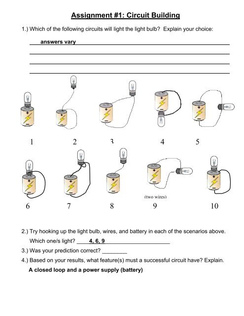
Assignment #1: Circuit Building<br />
1.) Which of the following circuits will light the light bulb? Explain your choice:<br />
answers vary<br />
1 2 3 4 5<br />
(two wires)<br />
6 7 8 9 10<br />
2.) Try hooking up the light bulb, wires, and battery in each of the scenarios above.<br />
Which one/s light? ____4, 6, 9_____________________<br />
3.) Was your prediction correct? ________<br />
4.) Based on your results, what feature(s) must a successful circuit have? Explain.<br />
A closed loop and a power supply (battery)
Assignment #2: Basic Circuits Internet Activity<br />
<br />
<br />
<br />
Open you web browser and go to:<br />
www.explorelearning.com/index.cfm?method=cResource.dspView&ResourceID=29<br />
Click on the Intro to E & M activity.<br />
Click on the Moving Charge button. Go through the activity and answer the following<br />
questions.<br />
1) What happens inside a wire when an electromotive force is applied? (2 nd screen)<br />
Electrons will flow through the wire (electrons jump from one nucleus to the next).<br />
2) What is current? (3 rd screen)<br />
The charge that passes over a certain amount of time<br />
q charge<br />
<strong>Current</strong> I <br />
t time<br />
<br />
<br />
3) How is a car driving down a flat open road like an electron moving through a wire with low<br />
resistance? (4 th screen)<br />
Easily being able to move down the road is similar to electron flow not being hindered<br />
when going through a wire.<br />
4) What happens when electrons get “joggled” around trying to move through a substance with<br />
moderate resistance? (4 th screen)<br />
They heat up the substance and prohibit a good electron flow.<br />
5) What is needed to make an electron move away from its nucleus? (5 th screen)<br />
ENERGY!<br />
6) What kind of energy is stored in a battery? (7 th screen)<br />
Chemical energy (voltaic cell – battery!)
Click on the button for Circuits.<br />
7) What four things make up a common circuit? (2 nd screen)<br />
1 – battery (power supply)<br />
2 – wire (to connect 2 ends of battery)<br />
3 – switch (on/off)<br />
4 – device (uses electricity to perform a function)<br />
8) Before closing the switch of the circuit, move your mouse onto the battery, wire and light bulb.<br />
What is happening in each when the switch is open? (4 th screen)<br />
- Battery: no reaction<br />
- Wire: electrons move about the closest nuclei<br />
- Light Bulb: no electrons move through the bulb, therefore there is no light<br />
9) Now close the switch of the circuit. Move your mouse onto the battery, wire and light bulb. What<br />
is happening in each when the switch is closed? (5 th screen)<br />
- Battery: reaction occurs – allows a positive and negative end of the battery<br />
- Wire: force supplied by battery causes electron to move towards positive side of<br />
battery<br />
- Light Bulb: electrons pass through the bulb. The filament has high resistance, causing<br />
material to get hot and give off light.<br />
10) In our labs we use resistors that cannot change. But in the next activity, set the battery to a<br />
certain voltage and use the slider to change the resistance. What happens to the current as<br />
resistance decreases? Explain.<br />
If voltage is kept constant and resistance is decreased, the current increases.<br />
(less resistance = less hindrance = greater flow of electrons)
Assignment #3: What is <strong>Current</strong>?<br />
We have looked at charges being transferred through friction, polarization, conduction, grounding,<br />
and induction. Now we are going to look at not only how much but how fast charge moves.<br />
1. What is the unit for Charge? __Coulomb (C)__<br />
2. What is a rate? a measured quantity per unit of time<br />
3. If I want to know the rate at which charges are moving, what mathematical operation should I use?<br />
__division __<br />
4. If <strong>Current</strong> is defined as the rate at which charges flow, what is the equation for current?<br />
<strong>Current</strong> <br />
charge<br />
time<br />
q<br />
I <br />
t<br />
5. Check your reference table for an equation involving current and charge. Was your prediction<br />
correct? If not, fix the equations above!<br />
***The units for <strong>Current</strong> are Amperes (Amps), abbreviated with a capital letter, A. The SI unit for<br />
<strong>Current</strong> is Coulombs per seconds or C/s<br />
6. <strong>Current</strong> is often compared to the amount of water flowing in a faucet or stream. If you have two<br />
streams flowing the other how do you know which one is moving faster or slower?<br />
More water flowing through a section in a faster amount of time<br />
7. Using the previous analogy, how can you tell if the current is faster or slower?<br />
More charge in a smaller amount of time<br />
8. 20 Coulombs of charge pass a given point in a conductor in 4.0 seconds. What is the current in<br />
the conductor?<br />
q<br />
20C<br />
I = 5 A (or 5 C/s)<br />
t 4s<br />
9. In a circuit with a battery supplying 12 volts, the current is 10 amperes.<br />
(a) How much charge flows through the circuit in 2.0 minutes?<br />
I <br />
q<br />
t<br />
q<br />
10 A ∆q = 1200 C<br />
120 s<br />
(b) How many electrons were transferred during these 2.0 minutes?<br />
1e<br />
1.610<br />
1 e = 1.6 x 10 -19 21<br />
C 1200C 7.510<br />
e<br />
19<br />
C
Assignment #4: What is Ohm’s Law?<br />
Question: What are voltage, current and resistance? How do they work?<br />
An Analogy:<br />
<strong>Current</strong><br />
Resistance<br />
Voltage<br />
Putting It All Together…<br />
a.) The gumballs in this demonstration represent the flow of _electrons_ through the pipe.<br />
b.) The height the pipe is raised above the desk represents potential difference, or<br />
_voltage_.<br />
c.) The nails placed in the pipe represent _resistance_ and slow down the flow of the<br />
gumballs.<br />
d.) The higher we raise the pipe, the _faster_ the gumballs flow; the more nails we place in<br />
the pipe, the __slower_ the gumballs flow.<br />
In summary, the current (rate of gumball flow per second) through the pipe depends on<br />
the voltage (height the end of the pipe is raised) and the resistance (number of nails in<br />
the pipe).<br />
Ohm’s Law is the mathematical formula used to explain this relationship.
Ohm’s law states that voltage is equal to current times resistance.<br />
Find a version of this equation on p. 4 of your Reference Tables & write it below!<br />
Questions: Show all work!<br />
R = resistance and has the unit of ohms (Ω)<br />
V = potential difference, or voltage, and has units of volts (V)<br />
I = current and has the unit of amperes (or amps, A)<br />
1. We can rearrange this equation to solve for V or I.<br />
a.) Solve for potential difference (V).<br />
V = IR<br />
b.) Solve for current (I) in Ohm’s Law.<br />
I = V<br />
R<br />
R <br />
V<br />
I<br />
2. What voltage is used by an electrical appliance that draws 0.4 amps of current and has a<br />
resistance of 3 ohms?<br />
I = 0.4 A<br />
R = 3 Ω<br />
V = IR = (0.4 A)(3 Ω) = 1.2 V<br />
3. A light bulb uses 240 volts of electricity and draws a current of 2 A. What is its resistance?<br />
V = 240 V<br />
I = 2 A<br />
R = V / I = (240 V) / (2 A) = 120 Ω<br />
4. Calculate the current used by a television that runs on 240 volts and has a resistance of 600 ohms.<br />
V = 240 V<br />
R = 600 Ω<br />
I = V / R = (240 V) / (600 Ω) = 0.4 A<br />
5. A 20 ohm resistor has 40 Coulombs of charge passing through it in 5 s. What is the potential<br />
difference across this resistor?<br />
R = 20 Ω I = ∆q / t = (40 C) / (5 s) = 8 A V = IR = (8 A) (20 Ω) = 160 V<br />
q = 40 C<br />
t = 5 s
6. A wire carries a current of 2.0-amperes. How many electrons pass a given point in this wire in 1.0<br />
second?<br />
I = 2 A I = ∆q / t ∆q = It = (2 A)(1 s) = 2 C<br />
t = 1 s<br />
1 e = 1.6 x 10 -19 C<br />
1e<br />
19<br />
2C 1.2510<br />
e<br />
19<br />
1.610<br />
C<br />
7. Complete the following table: V = IR<br />
<strong>Current</strong> - I<br />
(amps)<br />
Resistance - R<br />
(ohms)<br />
Voltage - V<br />
(volts)<br />
(a) 0.1 600 60<br />
(b) 0.25 1,000 250<br />
(c) 0.4 600 240<br />
(d) 0.5 480 240<br />
(e) 0.2 1,000 200
Assignment #5: Ohm’s Law Calculations<br />
1. What current flows through a circuit in which the resistance is 20 ohms and the potential<br />
difference is 90 volts?<br />
R = 20 Ω<br />
V = 90 V<br />
V<br />
R <br />
I<br />
90V<br />
20 I = 4.5 A<br />
I<br />
2. An ammeter and voltmeter in a circuit respectively read: 2.48 A and 88.4 V. What is the<br />
resistance of the circuit?<br />
I = 2.48 A<br />
V = 88.4 V<br />
R <br />
V<br />
I<br />
<br />
88.4V<br />
= 35.6 Ω<br />
2.48A<br />
3. A battery supplies a potential difference of 120 volts to a circuit in which the resistance is 15<br />
ohms. What current flows in this circuit?<br />
R = 15 Ω<br />
V = 120 V<br />
V<br />
R <br />
I<br />
120V<br />
15 I = 8 A<br />
I<br />
4. What potential difference is needed to produce a current of 345 milliamps in a circuit having a<br />
resistance of 8.74 ohms?<br />
I = 345 mA = 0.345 A<br />
R = 8.74 Ω<br />
V = IR = (0.345 A)(8.74 Ω) = 3.0 V<br />
5. When a wire is connected to a 9.0 V battery, the current is 0.020 A. What is the resistance of the<br />
wire?<br />
I = 0.02 A<br />
V = 9.0 V<br />
R <br />
V<br />
I<br />
<br />
9V<br />
= 450 Ω<br />
0.02A
6. A potential difference of 12 Volts is applied across a circuit having a 4 ohm resistance. What is<br />
the current in the circuit?<br />
R = 4 Ω<br />
V = 12 V<br />
V<br />
R <br />
I<br />
12V<br />
4 I = 3 A<br />
I<br />
For each of the following circuits use the rules and equations for electric circuits to determine the<br />
voltage (V), current (I), and resistance (R).<br />
7.<br />
V = 50 volts<br />
R <br />
V<br />
I<br />
R1 = ?<br />
Circuit V I R<br />
Total (T) 50 V 2 A 25 Ω<br />
8.<br />
V = 200 volts<br />
R1 = 20 ohms<br />
Circuit V I R<br />
Total (T) 50 V 10 A 20 Ω<br />
9.<br />
R1 = 35 <br />
Circuit V I R<br />
Total (T) 140 V 4 A 35 Ω
Assignment #6: Ohm’s Law Problems<br />
V<br />
__1___1. A graph of voltage (y-axis) versus current for a given resistor would produce a<br />
1) straight line 2) hyperbola 3) parabola 4) slope of zero<br />
__3___2. The rate of flow of electrons in a circuit is called<br />
R = V / I<br />
I<br />
1) resistance 2) voltage 3) current 4) power<br />
__3___3. A volt is a<br />
V = W / q = J / C<br />
1) joule/sec 2) coulomb/sec 3) joule/coulomb 4) coulomb/joule<br />
__2___4. An ampere is a<br />
I = Δq / t = C / s<br />
1) joule/sec 2) coulomb/sec 3) joule/coulomb 4) coulomb/joule<br />
__2___5. A 10 ohm resistor is connected to a power supply producing 5 amperes of current<br />
in that resistor. The voltage drop across the resistor must be<br />
R = V / I<br />
1) 2 volts 2) 50 volts 3) 0.5 volts 4) 15 volts V = IR<br />
V = (5A)(10Ω)<br />
__1___6. If the voltage provided to a resistor increases, the current through that resistor<br />
1) increases 2) decreases 3) remains the same I = V / R<br />
I & V have direct relationship!<br />
__2___7. As the resistance of a circuit increases, the current through that circuit<br />
1) increases 2) decreases 3) remains the same R = V / I<br />
R & I have inverse relationship!<br />
__3___8. Ten coulombs of charge pass a given point within a circuit in 2 seconds. The<br />
current in the circuit is<br />
I = Δq / t = 10C / 2s<br />
1) 20 amps 2) 12 amps 3) 5 amps 4) 0.2 amps<br />
__3___9. The opposition to the flow of electrons in a circuit is defined as electrical<br />
1) current 2) power 3) resistance 4) voltage drop<br />
__1___10. How much work is done in moving 100 coulombs of charge through a potential<br />
difference of 10 volts?<br />
V = W / q 10 V = W / 100 C<br />
1) 1000 joules 2) 100 joule 3) 10 joules 4) 1 joule
Assignment #7: Conductors vs. Insulators<br />
In order to understand resistance, we first have to look at the types of materials with which<br />
we’re trying to allow a current to flow.<br />
Directions: Obtain a conductivity tester from your teacher. Test the conductivity of 15 objects found<br />
throughout your classroom. You may want to consult p. 508 in your textbook to help in answering the<br />
questions that follow.<br />
Data:<br />
Object<br />
Conductivity<br />
1.) Define electrical conductivity.<br />
The ability of charge to flow through a material.<br />
2.) Out of the materials you tested, which would you rank as being conductors? Why?<br />
Varies – because it had the greatest amount of flashes with the conductivity<br />
tester.<br />
3.) What is a conductor?<br />
A material that easily allows a flow of electrons through it.<br />
4.) Out of the materials you tested, which would you rank as being non-conductors? Why?<br />
Varies – because it had the lowest amount of flashes with the conductivity tester.<br />
5.) Materials that are poor conductors are often called “insulators.” What is an insulator?<br />
A material that does NOT easily allow a flow of electrons through it.<br />
6.) Why are conductors important? Answers vary
7.) Why are insulators important? Answers vary<br />
8.) Most cords and electrical appliances have some sort of plastic surrounding the metal<br />
components. What is the purpose of the metal components? What is the purpose of the<br />
plastic?<br />
Metal components allow the flow of electrons (electricity), while the plastic<br />
prevents people from being shocked.<br />
View your teacher’s computer simulations for the following questions:<br />
9.) According to the atomic model, what do you observe as the difference between conductors<br />
and insulators? What about similarities?<br />
Difference – electrons move much more with conductors<br />
Similarities – both are positive ions with electrons on the outside. Only the e − can move.<br />
10.) A simple circuit is created using both an insulator and a conductor. Which material allows<br />
the bulb to be lit? Explain why.<br />
The conductor allows the bulb to be lit because it enables electrons to flow through it,<br />
while the insulator does not.<br />
NOTE: What do you notice about the direction of the flow of electrons in the circuit?<br />
Electrons flow away from the negative pole of the battery, and toward the positive pole<br />
of the battery.
Assignment #8: Resistance and Resistivity<br />
L<br />
A<br />
1.) A 0.686-meter-long wire has a cross-sectional area of 8.23 × 10 –6 meter 2 and a resistance of<br />
0.125 ohm at 20° Celsius. This wire could be made of<br />
R<br />
R = ρL / A<br />
a) aluminum b) nichrome c) copper d) tungsten<br />
ρ = RA / L = (0.125Ω)(8.23x10 -6 m 2 ) / (0.686 m)<br />
2.) A copper wire at 20°C has a length of 10 m and a cross-sectional area of 1.00 × 10 –3 m 2 . The wire<br />
is stretched, becomes longer and thinner, and returns to 20°C.<br />
a.) What effect does this stretching have on the wire’s resistance?<br />
R = ρL / A Stretching causes an increase in L and a decrease in A.<br />
Therefore, resistance will increase.<br />
b.) What effect does this stretching have on the wire’s resistivity?<br />
NO EFFECT! ρ depends only on the material. As long as the copper is still copper,<br />
resistivity isn’t affected.<br />
3.) A 6.0 m long copper wire has a cross-sectional area of 3.0 mm 2 . What is the resistance of the<br />
wire?<br />
A = 3 mm 2 x (1 m) 2 = 3 x 10 -6 m 2<br />
(1000mm) 2<br />
R = ρL / A = (1.72 x 10 -8 Ω·m)(6 m) / (3 x 10 -6 m 2 ) = 0.0344 Ω<br />
4.) What is the resistance of aluminum wire that is 4.0 m long and has a radius of 0.25 mm?<br />
r = 0.25 mm = 0.00025 m<br />
A = πr 2 = π((0.00025m) 2 ) = 1.96 x 10 -7 m 2<br />
R = ρL / A = (2.82 x 10 -8 Ω·m)(4 m) / (1.96 x 10 -7 m 2 ) = 0.58 Ω<br />
5.) A 10.0-meter length of copper wire is at 20°C. The radius of the wire is 1.0 × 10 –3 meter.<br />
a.) Determine the cross-sectional area of the wire.<br />
A = πr 2 = π((1.0 x 10 -3 m) 2 ) = 3.14 x 10 -6 m 2<br />
b.) Calculate the resistance of the wire.<br />
R = ρL / A = (1.72 x 10 -8 Ω·m)(10 m) / (3.14 x 10 -6 m 2 ) = 0.055 Ω
Assignment #9A: Series and Parallel Circuits Internet Activity<br />
Open your web browser to www.explorelearning.com<br />
Sign in using the Username: rh <strong>student</strong> 4 and Password: 4<br />
Search “Circuits” Run the gizmo Circuits<br />
Series Circuits<br />
1. Build the series circuit with three light bulbs and one battery shown at<br />
the right. To do this, drag the necessary parts from the COMPONENTS<br />
pane to the CIRCUIT BOARD.<br />
2. Click on the battery in your circuit, and then vary the voltage across the circuit by dragging the<br />
Selected battery voltage (volts) slider. What happens to the brightness of the lights when the<br />
voltage is increased?<br />
They get brighter<br />
3. When it is decreased?<br />
They get dimmer<br />
4. Click Show current. Set the Selected battery voltage to 1 volt and click Show current. The<br />
current is represented by moving arrows. Is there more or less current leaving the battery than<br />
flowing through ONE bulb?<br />
NO – the current stays the same!<br />
5. How does the flow of current change when the voltage is increased?<br />
<strong>Current</strong> increases<br />
6. When it is decreased?<br />
<strong>Current</strong> decreases<br />
7. Does the current ever reach an intersection in the wires?<br />
No<br />
8. Increase the voltage to 30 Volts and observe the brightness of the bulbs. Add three more bulbs to<br />
your circuit in series. How does the brightness of the bulbs change as more are added?<br />
They get dimmer
Parallel Circuits<br />
1. Build a parallel circuit as shown with three light bulbs and one<br />
battery. To do this, drag the necessary parts from the<br />
COMPONENTS pane to the CIRCUIT BOARD.<br />
2. Click on the battery in your circuit, and then vary the voltage<br />
across the circuit by dragging the Selected battery voltage (volts)<br />
slider. What happens to the brightness of the lights when the voltage<br />
is increased?<br />
They get brighter<br />
3. When it is decreased?<br />
They get dimmer<br />
4. Set the Selected battery voltage to 1 volt and click Show current. The current is represented by<br />
moving arrows. Is there more or less current leaving the battery than flowing through ONE bulb?<br />
More current leaves battery than flowing through the bulb<br />
5. What happens to the current when it reaches an intersection in the wires?<br />
It increases when joining back to “main line” from a parallel line (decreases when going<br />
from parallel line back to “main line”)<br />
6. Does an equal amount of current flow through each bulb?<br />
Yes<br />
7. Add one more bulb to the circuit in parallel. What happens to the brightness of the bulbs as more<br />
are added?<br />
No noticeable difference<br />
8. Keeping the voltage set to 1 volt, what happens to the current leaving the battery as more bulbs<br />
are added?<br />
<strong>Current</strong> increases<br />
9. Explain three differences between series and parallel circuits:<br />
<br />
<br />
<br />
For series circuits, adding resistors (lights) doesn’t change the current. For parallel,<br />
total current differs from the current going through each resistor.<br />
Adding bulbs in parallel doesn’t affect brightness, whereas in series the bulbs get<br />
dimmer.<br />
Placement: Series have resistors within same line, whereas parallel has them “in<br />
parallel” to one another
Assignment #9B: Series and Parallel Snap Circuits Activity<br />
Part 1: Series Circuits<br />
<br />
Use your supplies to build a circuit with single bulb connected to the battery as shown in the<br />
diagram.<br />
2. Observe the brightness of the one bulb.<br />
3. Draw a circuit showing TWO bulbs connected in a series circuit.<br />
4. Use your supplies to build this circuit. What happens to the brightness of the two bulbs<br />
when compared to one bulb alone?<br />
5. Gently unscrew one of the bulbs. What happens to the other bulb? Why?<br />
6. Add another battery pack to your circuit to increase the voltage. What happens to the<br />
brightness of the bulbs?<br />
7. What do you think is happening to the current flowing in the circuit as voltage increases?
Part 2: Parallel Circuits<br />
1. Connect the same two bulbs in a parallel circuit as shown.<br />
<br />
Explain how is this circuit different from a series circuit.<br />
<br />
Add another bulb to the circuit in parallel. Draw a picture of this parallel circuit in the space below.<br />
<br />
What happens to the brightness of the two bulbs in a parallel circuit when compared to three<br />
bulbs?<br />
<br />
Gently unscrew one of the bulbs. What happens to the two other bulbs? Why?<br />
Conclusion:<br />
<br />
Three light bulbs are connected in series and the filament in one of the bulbs burns out or breaks!<br />
How will this affect the other two bulbs? Explain your answer.<br />
<br />
Three light bulbs are connected in parallel and the filament in one of the bulbs burns out or<br />
breaks! How will this affect the other two bulbs? Explain your answer.<br />
<br />
Do you think the electrical circuits in your house are wired in series or in parallel? Explain.
Series Circuit Example:<br />
Assignment #10: Series Circuits Problems<br />
2.0-ohm (R 1 ), 3.0-ohm (R 2 ), and 1.0-ohm (R 3 ) resistors<br />
are connected in series to a voltage source of 12. volts<br />
(V B ) with a current of 2.0 amperes (I), as seen in the<br />
diagram to the right.<br />
Find the voltage drop at each resistor.<br />
Equations: I = I 1 = I 2 = I 3<br />
V = V 1 + V 2 + V 3<br />
R eq = R 1 + R 2 + R 3<br />
R = V / I (V = IR)<br />
Circuit V I R<br />
Total (T) 12. V 2 A 6.0 Ω<br />
1 4.0 V 2 A 2.0 Ω<br />
2 6.0 V 2 A 3.0 Ω<br />
3 2.0 V 2 A 1.0 Ω<br />
___A___ 1.) As resistors are added to a circuit in series, the total resistance of the circuit<br />
a) increases b) decreases c) remains the same R eq = R 1 + R 2 + …<br />
___A___ 2.) As resistors are added to a circuit in series, the voltage across each resistor<br />
a) increases b) decreases c) remains the same V = V 1 + V 2 + …<br />
___C___ 3.) As resistors are added to a circuit in series, the current in the circuit<br />
a) increases b) decreases c) remains the same<br />
I = I 1 = I 2 = …<br />
Base your answers to questions 4-8 on a circuit consisting of two 10 ohm light bulbs in series<br />
with a 40 volt power supply.<br />
___B___ 4.) The total resistance in the circuit is<br />
R eq = R 1 + R 2 = 10Ω + 10Ω<br />
a) 10 ohms b) 20 ohms c) 5 ohms d) 100 ohms<br />
___D___ 5.) The total current in the circuit is I = V / R = (40 V) / (20 Ω)<br />
a) 800 Amps b) 20 Amps c) 4 Amps d) 2 Amps<br />
___B___ 6.) The voltage drop across each light bulb is<br />
V = IR = (2A)(10Ω)<br />
a) 40 Volts b) 20 Volts c) 10 Volts d) 5 Volts
___B___ 7.) If a third bulb is added to a circuit, the brightness of the original two bulbs will<br />
a) increase b) decrease c) remain the same<br />
___C___ 8.) If one of the light bulbs should burn out, the other two bulbs will<br />
a) dim b) become brighter c) go out<br />
*there is no longer<br />
a complete circuit!<br />
Base your answers to questions 9 – 11 on the diagram below and the following information.<br />
A 4.0 ohm resistor (R 1 ), a 6.0 ohm resistor (R 2 ), and an unmarked resistor (R 3 ) are connected to a<br />
24-volt source as shown. The ammeter reads a current of 2.0 amps.<br />
9.) Determine the voltage drop across the 4.0 ohm resistor. Show all work.<br />
V 1 = IR 1 = (2 A)(4 ohm) = 8 V<br />
10.) Determine the value of R 3 . Show all work.<br />
R eq = V T = 24 V = 12 ohm<br />
I T 2 A<br />
R eq = R 1 + R 2 + R 3<br />
12 ohm = 4 ohm + 6 ohm + R 3 R 3 = 2 ohm<br />
11.) If the 4.0 ohm resistor (R 1 ) were removed from the circuit and the remaining circuit elements<br />
were reattached in series, what would be the reading on the ammeter? Show all work.<br />
R eq = R 2 + R 3 = 6 ohm + 2 ohm = 8 ohm<br />
I T = V T<br />
R eq<br />
= 24 V = 3 A<br />
8 ohm
Assignment # 11: OUTSMARTING THE REGENTS EXAM<br />
Although the NYS Regents Physics Exam is a difficult test, many of the questions you will face<br />
require NO knowledge of physics whatsoever!! All you need to answer the questions correctly is a<br />
Reference Table, eyeballs and just a little bit of thinking.<br />
Here is a typical problem taken from the January 2008 Regents Exam:<br />
A circuit consists of a 10.0-ohm resistor, a 15.0-ohm resistor, and a 20.0-ohm resistor connected<br />
in parallel across a 9.00-volt battery. What is the equivalent resistance of this circuit?<br />
STEP 1: Read the problem twice. Pick out the <strong>key</strong> words: circuit, parallel, and equivalent resistance.<br />
STEP 2: Look at your Reference Tables. Again, using only<br />
your eyeballs, look on the Electricity page in the Circuits<br />
section and find the equations for Parallel Circuits.<br />
It doesn’t even matter if you know what a parallel circuit is!<br />
Just find the equation you need and solve it. Ka-ching!<br />
1/Req = 1/R1 + 1/R2 + 1/R3<br />
1/Req = 1/10 + 1/15 + 1/20<br />
1/Req = 0.1 + 0.067 + 0.05<br />
1/Req = 0.2167<br />
Req = 4.62 ohms<br />
STEP 3: Think carefully. Predict what the other choices will be! The Regents WILL try to trick you<br />
and offer choices that may seem right if you don’t think.<br />
<br />
<br />
<br />
So if the correct answer is choice (a) 4.62 ohms, choice (b) will be 0.2167 ohms for the<br />
<strong>student</strong>s who forget to cross multiply in the last step.<br />
Choice (c) is going to be 45 ohms, for the <strong>student</strong>s who did not check the Reference Tables<br />
and simply added the resistors to find the equivalent resistance. (This would be correct for a<br />
series circuit!)<br />
Choice (d) will probably be 9.00 volts, for <strong>student</strong>s who don’t realize voltage has nothing to<br />
do with the question.
Now you try one. Here’s another problem from a Regents Exam.<br />
A circuit consists of 5.0-ohm resistor, a 10.0-ohm resistor, and a 15.0-ohm<br />
resistor connected in series across a 9.00 volt battery. What is the current<br />
flowing through the 10.0-ohm resistor?<br />
What is the correct answer? Show all work.<br />
(a) __0.3 A______<br />
R eq = R 1 + R 2 + R 3 = 5 Ω + 10 Ω + 15 Ω = 30 Ω<br />
R = V / I 30 Ω = 9 V / I I = 9 V / 30 Ω = 0.3 A<br />
I = I 1 = I 2 = I 3 = 0.3 A<br />
What will choice (b) be? Explain.<br />
(b) __3.33 A_____<br />
3.33 A for those who do 30 Ω / 9 V when solving for I.<br />
What will choice (c) be? Explain.<br />
(c) __0.9 A______<br />
0.9 A for those who thought V = V 1 = V 2 = V 3 and do I = V / R = 9 V / 10 Ω<br />
What will choice (d) be? Explain.<br />
(d) __30 A______<br />
30 A for those who just add up all of the resistors.<br />
Here’s another:<br />
A circuit consists of three 10.0-ohm resistors connected in parallel across<br />
an 18.0 volt battery. What is the equivalent resistance of this circuit?<br />
What is the correct answer? Show all work.<br />
(a) __3.33 Ω____<br />
1/Req = 1/R1 + 1/R2 + 1/R3<br />
1/Req = 1/10 + 1/10 + 1/10<br />
1/R eq = 3/10<br />
R eq = 10/3 = 3.33 Ω<br />
What will choice (b) be? Explain.<br />
(b) __0.3 Ω_____<br />
0.3 Ω for those that forget to cross multiply the last step<br />
What will choice (c) be? Explain.<br />
(c) __ 30 Ω_____<br />
30 Ω for those that use the series circuit rules<br />
What will choice (d) be? Explain.<br />
(d) ___18 Ω____<br />
18 Ω for those that think it has something to do with the total voltage
Assignment #12A: Parallel Circuits Problems<br />
Practice filling in the following VIR tables.<br />
10 Ω<br />
Circuit V I R<br />
1 1.5 V 0.3 A 5 Ω<br />
2 1.5 V 0.15 A 10 Ω<br />
Total (T) 1.5 V 0.45 A 3.333 Ω<br />
4 A<br />
2 Ω<br />
4 Ω<br />
Circuit V I R<br />
1 3.2 V 1.6 A 2 Ω<br />
2 3.2 V 1.6 A 2 Ω<br />
3 3.2 V 0.8 A 4 Ω<br />
Total (T) 3.2 V 4 A 0.8 Ω
Assignment #12B: Parallel Circuits Problems<br />
For each of the following circuits use the rules and equations for circuits to determine the voltage (V),<br />
current ( I ) and resistance (R) for each resistor and the total circuit by making a VIR chart.<br />
1.)<br />
V = 200 volts<br />
R1 = 20<br />
Circuit V I R<br />
1 200 V 10 A 20 Ω<br />
2 200 V 5 A 40 Ω<br />
T 200 V 15 A 13.33 Ω<br />
R2 = 40 <br />
V = ?<br />
2.)<br />
i = 5 a<br />
R1 = 30 <br />
Circuit V I R<br />
T 100 V 5 A 20 Ω<br />
1 100 V 3.33 A 30 Ω<br />
2 100 V 1.67 A 60 Ω<br />
R2 = 60<br />
3.)<br />
V = 60 volts<br />
i = 2 a<br />
R1<br />
R2<br />
Circuit V I R<br />
1 60 V 0.5 A 120 Ω<br />
2 60 V 1.5 A 40 Ω<br />
T 60 V 2 A 30 Ω<br />
i = 1.5 a
Base your answers to questions 4 – 6 on the diagram below and the following information.<br />
A 20.0 ohm resistor (R 1 ), a 30.0 ohm resistor (R 3 ), and an unmarked resistor (R 2 ) are connected to a<br />
24-volt source as shown. The ammeter reads a current of 3.0 amps.<br />
4.) Determine the voltage drop across the 20.0 ohm resistor. Show all work.<br />
V = V 1 = V 2 = V 3 = 24 V<br />
5.) Determine the value of R 2 . Show all work.<br />
R eq = V / I = 24 V / 3 A = 8 Ω<br />
1 / R eq = 1/R 1 + 1/R 2 + 1/R 3<br />
(1 / 8 Ω) = (1 / 20 Ω) + (1 / R 2 ) + (1 / 30 Ω)<br />
0.125 = 0.0833 + (1 / R 2 )<br />
1 / R 2 = 0.0417<br />
R 2 = 24 Ω<br />
6.) If the 20.0 ohm resistor were removed from the circuit and the remaining circuit elements were<br />
reattached in parallel, what would be the reading on the ammeter? Show all work.<br />
I 2 = V 2 / R 2 = 24 V / 24 Ω = 1 A<br />
I 3 = V 3 / R 3 = 24 V / 30 Ω = 0.8 A<br />
I = I 2 + I 3 = 1 A + 0.8 A = 1.8 A
Answer the following questions:<br />
__B____ 1.) As resistors are added to a circuit in parallel, the total resistance of the circuit<br />
a) increases b) decreases c) remains the same<br />
__C____ 2.) As resistors are added to a circuit in parallel, the voltage across each resistor<br />
a) increases b) decreases c) remains the same<br />
__A____ 3.) As resistors are added to a circuit in parallel, the current in the circuit R T decreases,<br />
a) increases b) decreases c) remains the same therefore<br />
I T decreases<br />
Base your answers to questions 4-9 on a circuit consisting of two 10 ohm light bulbs in<br />
parallel with a 40 volt power supply.<br />
4.) Using the circuit symbols found in the Reference Tables for Physical Setting/Physics,<br />
draw a diagram of these components in a parallel circuit.<br />
A<br />
Ammeter goes in series<br />
with the rest of the circuit,<br />
before any junctions<br />
V<br />
Voltmeter goes in parallel<br />
with the rest of the circuit<br />
to measure how much<br />
voltage (potential) is added<br />
by the battery<br />
5.) In the diagram above, draw in a voltmeter and ammeter in the correct positions to<br />
measure the total amount of voltage and current, respectively, that are being delivered<br />
to the circuit.<br />
1/R eq = 1/10Ω + 1/10Ω = 2/10Ω R eq = 5Ω<br />
__A____ 6.) The total current in the circuit is<br />
I = V / R = (40V) / (5Ω)<br />
a) 8 Amps b) 20 Amps c) 4 Amps d) 2 Amps<br />
__A____ 7.) The voltage drop across each light bulb is V = V 1 = V 2<br />
a) 40 Volts b) 20 Volts c) 10 Volts d) 5 Volts<br />
__C____ 8.) If a third bulb is added to a circuit in parallel, the brightness of the original two<br />
bulbs will<br />
a) increase b) decrease c) remain the same<br />
__D____ 9.) If one of the light bulbs should burn out, the other two bulbs will<br />
a) dim b) become brighter c) go out d) remain the same
Assignment #12C: Parallel Circuits Problems<br />
1. A battery of 24 volts is<br />
connected to a circuit as<br />
shown at the right.<br />
6 <br />
4 <br />
Determine each of the following:<br />
a) The equivalent resistance of the 4 ohm and 8 ohm<br />
resistors.<br />
8 <br />
R s = R 1 + R 2 = 4 Ω + 8 Ω = 12 Ω<br />
b) The equivalent resistance of the 4 ohm and 8 ohm resistors plus the 12 ohm resistor.<br />
1/R p = 1/R 12 + 1/R s = 1/12 Ω + 1/12 Ω = 2/12 Ω = 6 Ω<br />
c) The total resistance of the circuit<br />
R s = R 6 + R p = 6 Ω + 6 Ω = 12 Ω<br />
d) The current in the 6 ohm resistor.<br />
I = V/R eq = 24 V / 12 Ω = 2 A<br />
e) The rate at which energy is dissipated (POWER) in the 12 ohm resistor.<br />
Power (Topic #5) = I 2 R = (1 A) 2 (12 Ω) = 12 Watts
2. Three resistors are arranged in a circuit as shown. The battery has an unknown but constant<br />
voltage. Determine the potential difference across resistor R1.<br />
.<br />
<br />
Circuit V I R<br />
T 4.8 V 0.4 A 12 Ω<br />
1 1.2 V 0.3 A 4 Ω<br />
2 1.2 V 0.1 A 12 Ω<br />
3 3.6 V 0.4 A 9 Ω<br />
*R 1 & R 2 are in parallel!<br />
Find R T for these, then R eq !<br />
**PARALLEL RULES FOR R 1 & R 2 !**<br />
3. Determine the resistance of R 1<br />
i = 4 a<br />
V = 100 volts<br />
R1 = 10 <br />
R 2 = ?<br />
R1 = ?<br />
Circuit V I R<br />
T 100 V 4 A 25 Ω<br />
1 15 V 1.5 A 10 Ω<br />
2 85 V 1.5 A 56.67 Ω<br />
3 100 V 2.5 A 40 Ω<br />
*R 1 & R 2 are in series!<br />
Find R T for these, then R eq !<br />
R3 = 40<br />
**SERIES RULES FOR R 1 & R 2 !**
Assignment #13: Electric Power Problems<br />
1.) How much time is required for an operating 100 watt light bulb to dissipate 10 Joules of electrical<br />
energy?<br />
W = Pt<br />
a) 1 sec b) 0.1 sec c) 10 sec d) 1000 sec<br />
2.) While operating at 120 Volts, an electric toaster has a resistance of 15 ohms. The power used by<br />
the toaster is P = V 2 / R<br />
a) 8 W b) 120 W c) 960 W d) 1800 W<br />
3.) An electric clothes dryer consumes 6 x 10 6 J of energy while operating at 220 volts for 30<br />
minutes. During operation, the dryer draws a current of W = VIt<br />
a) 10 Amps b) 15 Amps c) 20 Amps d) 25 Amps<br />
4.) What is the approximate amount of electrical energy needed to operate a 1600 Watt toaster for<br />
60 seconds? W = Pt<br />
a) 27 J b) 1500 J c) 1700 J d) 96,000 J<br />
5.) Electric power is measured in<br />
a) Volts b) Joules/sec c) Coulombs/sec d) Joules/ Coulomb<br />
6.) Electric power can be calculated by<br />
a) IV b) V 2 /R c) I 2 R d) all of the above<br />
7.) Electric energy is measured in<br />
a) Joules b) Watts c) Coulombs d) Ohms<br />
8.) Electric energy can be calculated by<br />
a) Pt b) VIt c) I 2 Rt d) all of the above<br />
9.) A potential difference of 60 V is applied across a 15 ohm resistor. What is the power dissipated<br />
in the resistor? P = V 2 / R<br />
a) 240 J b) 240 W c) 2.4 W d) 12 W<br />
10.) A current of 0.4 amps is measured in a 150 ohm resistor. How much energy is expended by the<br />
resistor in 30 seconds? W = I 2 Rt<br />
a) 72 J b) 240 J c) 600 J d) 720 J
Base your answers to the following questions on the diagram below. Show all work!<br />
1.) What is the current reading in ammeter A1?<br />
I = I 1 + I 2<br />
10 A = I 1 + 4 A<br />
I 1 = 6 A<br />
2.) Determine the power developed in resistor R2 alone.<br />
P 2 = I 2 2 R 2 = (4 A) 2 (30 Ω) = 480 W<br />
3.) Determine the power developed in resistor R1 alone.<br />
P 1 = I 1 2 R 1 = (6 A) 2 (20 Ω) = 720 W<br />
4.) How much electric energy is used by the 30 ohm resistor in 10 minutes?<br />
t = 10 min = 600 s<br />
W 2 = P 2 t = (480 W)(600 s) = 288,000 J<br />
5.) What would happen to the current in ammeter A 2 if resistor R 1 was removed? Explain.<br />
It wouldn’t change! Since A 2 depends solely on the voltage and R 2 (Ohm’s Law), its<br />
value is unaffected by any changes to R 1 .<br />
6.) Given the following information for a radio:<br />
P = 12 W<br />
V = 120 V<br />
Used for 30 min<br />
Cost of energy is 7 cents ( 0.07 $) per kilowatt-hour<br />
Calculate:<br />
a) the current through the radio:<br />
P = VI I = P / V = (12 W) / (120 V) = 0.1 A<br />
b) the amount of energy used (in kilowatt-hours)<br />
P = 12 W = 0.012 kW<br />
W = Pt = (0.012 kW)(0.5 hr) = 0.006 kW-hr<br />
c) the cost of your listening pleasure<br />
0.006 kW-hr x $0.07 = $0.00042<br />
1 kW-hr
Assignment #14: Circuit Simulation – Review<br />
1. Open up Internet Explorer and navigate to:<br />
http://phet.colorado.edu/en/simulation/circuit-construction-kit-dc<br />
2. Click on “Run Now!”<br />
3. Using four light bulbs and four batteries as well as a switch and as many wires as you need, build a<br />
circuit similar to used for Holiday lights, where one bulb burning out causes all bulbs to fail. Draw<br />
the schematic below (show resistors for light bulbs)<br />
4. What type of circuit is this? ______series________ (series/parallel)<br />
5. Add the Ammeter to the circuit. How much current is flowing through each of the light bulbs (L)?<br />
L 1 : ___0.9 A___ L 2 : __0.9 A ____ L 3 : __0.9 A ____ L 4 : __0.9 A ___<br />
6. What do you notice about the currents across each light bulb? ___the same__________<br />
7. Apply the Voltmeter across all four batteries. How much voltage is being applied to the entire<br />
circuit? _____36 V________<br />
8. Apply the Voltmeter across each of the light bulbs. How much Voltage is dropped across each?<br />
L 1 : __9 V____ L 2 : ___9 V____ L 3 : ___9 V___ L 4 : __9 V___<br />
9. How does your answer for question #7 compare to the sum of your answers for question #8?<br />
The same! (36 V = 9 V + 9 V + 9 V + 9 V)<br />
10. How much power is being dissipated by each of the light bulbs? Show all work:<br />
L 1 : __8.1 W__<br />
P = VI = (9 V)(0.9 A) = 8.1 W<br />
L 2 : __8.1 W__<br />
L 3 : __8.1 W__<br />
L 4 : __8.1 W__
11. Using four light bulbs and four batteries, and as many wires and resistors as required, design a<br />
circuit such that when one bulb goes out, the other three bulbs continue to function. Draw the<br />
schematic below (show resistors for light bulbs)<br />
12. What type of circuit is this? ____parallel______ (series/parallel)<br />
13. Add the Ammeter to the beginning of the circuit (next to the batteries). How much current is being<br />
delivered into the entire circuit? _____14.4 A_______<br />
14. Add the Ammeter to the circuit. How much current is flowing through each of the light bulbs (L)?<br />
L 1 : __3.6 A___ L 2 : __3.6 A___ L 3 : __3.6 A___ L 4 : __3.6 A___<br />
15. How does your answer for question #13 compare to the sum of your answers for question #14?<br />
The same! (14.4 A = 3.6 A + 3.6 A + 3.6 A + 3.6 A)<br />
16. Apply the Voltmeter across all four batteries. How much voltage is being applied to the entire<br />
circuit? _____36 V________<br />
17. Apply the Voltmeter across each of the light bulbs. How much Voltage is dropped across each?<br />
L 1 : ___36 V_____ L 2 : ___36 V_____ L 3 : ___36 V_____ L 4 : ___36 V_____<br />
18. What do you notice about the voltage drop across each light bulb? _____the same!________<br />
19. How does your answer to question #16 compare to you answer to question #17? ___the same!_<br />
20. How much power is being dissipated by each of the light bulbs? Show all work:<br />
L 1 : __130 W____<br />
P = VI = (36 V)(3.6 A) = 130 W<br />
L 2 : __130 W____<br />
L 3 : __130 W____<br />
L 4 : __130 W____
21. Using four light bulbs and four batteries, design a circuit such that each light bulb has a different<br />
brightness. Draw the circuit schematic below. Indicate which bulb is the brightest, the dimmest, etc.<br />
50 Ω 10 Ω 76 Ω 25 Ω<br />
#3 brightest dimmest #2<br />
(#1) (#4)<br />
22. You have thirteen batteries in a single circuit and one light bulb. There are no resistors or<br />
anything to calm the flow of energy (amps). What will the circuit ultimately do? Build it and see.<br />
Explain below.<br />
Combust! Too much electrical energy, therefore extra is converted to<br />
heat/thermal energy<br />
23. Now experiment with different resistors and/or light bulbs to see how many ohms it takes to calm<br />
the thirteen batteries it takes. Record what it took and explain how certain variables effect flow of<br />
energy.<br />
It takes about 12 ohms of resistance. More resistance = less current = less energy<br />
24. Build a smaller circuit (2 or 3 batteries with one light bulb is big enough). Click on the “Advanced”<br />
Settings in the bottom right corner. Describe how the brightness of the bulb changes as the “Wire<br />
Resistivity” is changed from “Almost none” to “lots”.<br />
More resistivity = dimmer light
Assignment #15: Graphing & <strong>Current</strong> Electricity<br />
1.) The graph to the right shows the relationship between the<br />
potential difference across a metallic conductor and the electric<br />
current through the conductor at constant temperature T 1 .<br />
Which graph best represents the relationship between potential<br />
difference and current for the same conductor maintained at a<br />
higher constant temperature, T2?<br />
R = V / I = slope of line. Higher T = higher R = higher slope<br />
2.) A long copper wire was connected to a voltage source. The voltage was varied and the<br />
current through the wire measured, while temperature was held constant. The collected data are<br />
represented by the graph below.<br />
Using the graph, the resistance of the copper wire is approximately<br />
(1) 8.0 Ω (2) 25 Ω (3) 30 Ω (4) 2.5 Ω
3.) A variable resistor was connected to a battery. As the resistance was adjusted, the current<br />
and power in the circuit were determined. The data are recorded in the table below.<br />
Using the information in the data table, construct a line<br />
graph on the grid provided, following the directions below.<br />
a.) Plot the data points for power versus current.<br />
Allow 1 credit for accurately plotting the data points (±0.3 grid space) for power vs. current.<br />
b.) Draw the best-fit line.<br />
Allow 1 credit for drawing a straight best-fit line. If one or more points are plotted incorrectly in<br />
question 3a, but a best-fit line is drawn, allow this credit.<br />
c.) Using your graph, determine the power delivered to the circuit at a current of 3.5 amperes.<br />
10.5 W ± 0.3 W<br />
Allow credit for an answer that is consistent with the <strong>student</strong>’s answer to question 3b.<br />
d.) Calculate the slope of the graph. [Show all calculations, including the equation and substitution<br />
with units.]<br />
Note: The slope may be determined by direct substitution of<br />
data points ONLY IF the data values are on the best-fit line.<br />
e.) What is the physical significance of the slope of the graph?<br />
Voltage and/or Potential Difference
4.) An experiment was performed using various lengths of a conductor of uniform crosssectional area.<br />
The resistance of each length was measured and the data recorded in the table below.<br />
Using the information in the data table, construct a graph on the grid provided following the<br />
directions below.<br />
a.) Mark an appropriate scale on the axis labeled “Length (m).”<br />
b.) Plot the data points for resistance versus length.<br />
c.) Draw the best-fit line.<br />
d.) Calculate the slope of the best-fit line. [Show all work, including the equation and substitution<br />
with units.]
1.) 2<br />
2.) 2<br />
3.) 1<br />
4.) 1<br />
5.) 4<br />
6.) 2<br />
7.) 4<br />
8.) 4<br />
9.) 1<br />
10.) 1<br />
11.) 3<br />
12.) 2<br />
13.) 3<br />
14.) 4<br />
15.)<br />
Assignment #16: Regents <strong>Current</strong> Electricity Problems<br />
16.)
17.)<br />
18.)<br />
19.)
20.)<br />
21.)<br />
22.)