Sigma-II Series SGMBH/SGDM/SGDH USER'S MANUAL
Sigma-II Series SGMBH/SGDM/SGDH USER'S MANUAL
Sigma-II Series SGMBH/SGDM/SGDH USER'S MANUAL

Create successful ePaper yourself
Turn your PDF publications into a flip-book with our unique Google optimized e-Paper software.
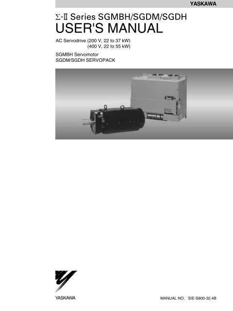
<strong>Series</strong> <strong>SGMBH</strong>/<strong>SGDM</strong>/<strong>SGDH</strong><br />
<strong>USER'S</strong> <strong>MANUAL</strong><br />
AC Servodrive (200 V, 22 to 37 kW)<br />
(400 V, 22 to 55 kW)<br />
<strong>SGMBH</strong> Servomotor<br />
<strong>SGDM</strong>/<strong>SGDH</strong> SERVOPACK<br />
YASKAWA<br />
YASKAWA<br />
<strong>MANUAL</strong> NO. SIE-S800-32.4B
Copyright © 2002 YASKAWA ELECTRIC CORPORATION<br />
All rights reserved. No part of this publication may be reproduced, stored in a retrieval system,<br />
or transmitted, in any form, or by any means, mechanical, electronic, photocopying, recording,<br />
or otherwise, without the prior written permission of Yaskawa. No patent liability is assumed<br />
with respect to the use of the information contained herein. Moreover, because Yaskawa is constantly<br />
striving to improve its high-quality products, the information contained in this manual is<br />
subject to change without notice. Every precaution has been taken in the preparation of this<br />
manual. Nevertheless, Yaskawa assumes no responsibility for errors or omissions. Neither is<br />
any liability assumed for damages resulting from the use of the information contained in this<br />
publication.
About this Manual<br />
• This manual provides the following information for the Σ-<strong>II</strong> <strong>Series</strong> <strong>SGMBH</strong> Servomotor,<br />
22-kW to 37-kW <strong>SGDM</strong> SERVOPACK, and 22-kW to 55-kW <strong>SGDH</strong><br />
SERVOPACK.<br />
• Procedures for installing and wiring the servomotor and the SERVOPACK.<br />
• Procedures for trial operation of the Servodrive.<br />
• Procedures for using functions and adjusting the servodrives.<br />
• Procedures for using the built-in Panel Operator and the Hand-held Digital Operator.<br />
• Ratings and specifications for standard models.<br />
• Procedures for maintenance and inspection.<br />
• Intended Audience<br />
This manual is intended for the following users.<br />
• Those designing Σ-<strong>II</strong> <strong>Series</strong> servodrive systems.<br />
• Those installing or wiring Σ-<strong>II</strong> <strong>Series</strong> servodrives.<br />
• Those performing trial operation or adjustments of Σ-<strong>II</strong> <strong>Series</strong> servodrives.<br />
• Those maintaining or inspecting Σ-<strong>II</strong> <strong>Series</strong> servodrives.<br />
• Description of Technical Terms<br />
In this manual, the following terms are defined as follows:<br />
• Servomotor = Σ-<strong>II</strong> <strong>Series</strong> <strong>SGMBH</strong> servomotor.<br />
• SERVOPACK = Σ-<strong>II</strong> <strong>Series</strong> <strong>SGDM</strong> and <strong>SGDH</strong> SERVOPACK.<br />
• Servodrive = A set including a servomotor and Servo Amplifier.<br />
• Servo System = A servo control system that includes the combination of a servodrive<br />
with a host computer and peripheral devices.<br />
• Indication of Reverse Signals<br />
In this manual, the names of reverse signals (ones that are valid when low) are written with a<br />
forward slash (/) before the signal name, as shown in the following example:<br />
• S-ON = /S-ON<br />
• P-CON = /P-CON<br />
iii
• Visual Aids<br />
The following aids are used to indicate certain types of information for easier reference.<br />
IMPORTANT<br />
Indicates important information that should be memorized, including precautions such as<br />
alarm displays to avoid damaging the devices.<br />
INFO<br />
Indicates supplemental information.<br />
EXAMPLE<br />
Indicates application examples.<br />
TERMS<br />
Indicates definitions of difficult terms or terms that have not been previously explained in<br />
this manual.<br />
The text indicated by this icon explains the operating procedure using Hand-held type Digital<br />
Operator (Type: JUSP-OP02A-2).<br />
JUSP-OP02A-2<br />
iv
Related Manuals<br />
• Refer to the following manuals as required.<br />
• Also, keep this manual in a safe place so that it can be referred to whenever necessary.<br />
Manual Name Manual Number Contents<br />
Σ <strong>Series</strong>/Σ-ΙΙ <strong>Series</strong><br />
SERVOPACKs Personal<br />
Computer Monitoring<br />
Software Operation Manual<br />
Σ-ΙΙ <strong>Series</strong><br />
SGMH/<strong>SGDM</strong><br />
Digital Operator<br />
Operation Manual<br />
SIE-S800-35<br />
TOE-S800-34<br />
Describes the applications and operation of<br />
software for the Σ <strong>Series</strong>/Σ-<strong>II</strong> <strong>Series</strong><br />
servodrive monitoring devices for use on<br />
personal computers.<br />
Provides detailed information on the operation<br />
of the JUSP-OP02A-2 Digital Operator,<br />
which is an optional product.<br />
Safety Information<br />
The following conventions are used to indicate precautions in this manual.<br />
Failure to heed precautions provided in this manual can result in serious or possibly even<br />
fatal injury or damage to the products or to related equipment and systems.<br />
WARNING<br />
CAUTION<br />
PROHIBITED<br />
Indicates precautions that, if not heeded, could possibly result in loss of life or serious<br />
injury.<br />
Indicates precautions that, if not heeded, could result in relatively serious or minor<br />
injury, damage to the product, or faulty operation.<br />
Indicates actions that must never be taken.<br />
v
Safety Precautions<br />
The following precautions are for checking products upon delivery, installation, wiring,<br />
operation, maintenance and inspections.<br />
• Checking Products upon Delivery<br />
CAUTION<br />
• Always use the servomotor and the SERVOPACK in one of the specified combinations.<br />
Not doing so may cause fire or malfunction.<br />
• Installation<br />
CAUTION<br />
• Never use the products in an environment subject to water, corrosive gases, inflammable gases, or<br />
combustibles.<br />
• Doing so may result in electric shock or fire.<br />
vi
• Wiring<br />
WARNING<br />
• Connect the ground terminal<br />
to electrical codes (ground resistance: 100 Ω or less).<br />
Improper grounding may result in electric shock or fire.<br />
• Use the thermal protector built into the servomotor according to either of the two following methods.<br />
<strong>SGMBH</strong> servomotors are cooled by a fan. If the fan is defective or power to the fan is disconnected, heat<br />
from the motor may result in burns or fire.<br />
Method 1:<br />
• Wire the output from the thermal protector to the host controller and turn OFF the servo when the<br />
thermal protector operates.<br />
Main circuit<br />
contactors<br />
Main circuit<br />
power supply<br />
SERVOPACK<br />
M<br />
Thermal<br />
protector<br />
PG<br />
Servo OFF<br />
Host Controller<br />
Method 2:<br />
• Wire the thermal protector to the operating circuit of the main circuit contactors or the host controller<br />
and turn OFF the main circuit when the thermal protector operates.<br />
Main circuit<br />
power supply<br />
Main circuit<br />
contactors<br />
SERVOPACK<br />
M<br />
PG<br />
Thermal<br />
protector<br />
To main circuit<br />
contactors<br />
Host controller or operating<br />
circuit of main circuit contactors<br />
CAUTION<br />
• Do not connect a three-phase power supply to the SERVOPACK’s U, V, or W output terminals.<br />
Doing so may result in injury or fire.<br />
• Securely fasten the power supply terminal screws and motor output terminal screws.<br />
Not doing so may result in fire.<br />
vii
• Operation<br />
• Never touch any rotating motor parts while the motor is running.<br />
Doing so may result in injury.<br />
WARNING<br />
CAUTION<br />
• Conduct trial operation on the servomotor alone with the motor shaft disconnected from machine to<br />
avoid any unexpected accidents.<br />
Not doing so may result in injury.<br />
• Before starting operation with a machine connected, change the settings to match the parameters<br />
of the machine.<br />
Starting operation without matching the proper settings may cause the machine to run out of control or malfunction.<br />
• Before starting operation with a machine connected, make sure that an emergency stop can be<br />
applied at any time.<br />
Not doing so may result in injury.<br />
• Do not touch the heat sinks during operation.<br />
Doing so may result in burns due to high temperatures.<br />
• Maintenance and Inspection<br />
WARNING<br />
• Never touch the inside of the SERVOPACKs.<br />
Doing so may result in electric shock.<br />
• Do not remove the panel cover while the power is ON.<br />
Doing so may result in electric shock.<br />
• Do not touch terminals for five minutes after the power is turned OFF.<br />
Residual voltage may cause electric shock.<br />
CAUTION<br />
• Do not disassemble the servomotor.<br />
Doing so may result in electric shock or injury.<br />
• Do not attempt to change wiring while the power is ON.<br />
Doing so may result in electric shock or injury.<br />
viii
• General Precautions<br />
Note the following to ensure safe application.<br />
• The drawings presented in this manual are sometimes shown without covers or protective guards. Always<br />
replace the cover or protective guard as specified first, and then operate the products in accordance with<br />
the manual.<br />
• The drawings presented in this manual are typical examples and may not match the product you received.<br />
• This manual is subject to change due to product improvement, specification modification, and manual<br />
improvement. When this manual is revised, the manual code is updated and the new manual is published<br />
as a next edition.<br />
• If the manual must be ordered due to loss or damage, inform your nearest Yaskawa representative or one of<br />
the offices listed on the back of this manual.<br />
• Yaskawa will not take responsibility for the results of unauthorized modifications of this product. Yaskawa<br />
shall not be liable for any damages or troubles resulting from unauthorized modification.<br />
<strong>SGDM</strong> and <strong>SGDH</strong> SERVOPACKs Standards and Certification<br />
<strong>SGDM</strong> and <strong>SGDH</strong> SERVOPACKs conform to the following standards. However, because<br />
this product is a built-in type, reconfirmation is required after being installed in the final<br />
product.<br />
• EN55011 group 1 class A<br />
• EN50082-2<br />
ix
CONTENTS<br />
About this Manual - - - - - - - - - - - - - - - - - - - - - - - - - - - - - - - - - - - - - - iii<br />
Related Manuals - - - - - - - - - - - - - - - - - - - - - - - - - - - - - - - - - - - - - - - v<br />
Safety Information - - - - - - - - - - - - - - - - - - - - - - - - - - - - - - - - - - - - - - v<br />
Safety Precautions- - - - - - - - - - - - - - - - - - - - - - - - - - - - - - - - - - - - - - vi<br />
<strong>SGDM</strong> and <strong>SGDH</strong> SERVOPACKs Standards and Certification- - - - - - - ix<br />
1 For First-time Users of AC Servos<br />
1.1 Basic Understanding of AC Servos - - - - - - - - - - - - - - - - - - 1-2<br />
1.1.1 Servo Mechanisms - - - - - - - - - - - - - - - - - - - - - - - - - - - - - - - - - - - - 1-2<br />
1.1.2 Technical Terms- - - - - - - - - - - - - - - - - - - - - - - - - - - - - - - - - - - - - - - 1-4<br />
1.2 Configuration of Servo System - - - - - - - - - - - - - - - - - - - - - 1-5<br />
1.3 Features of Σ-ΙΙ <strong>Series</strong> Servos - - - - - - - - - - - - - - - - - - - - - 1-10<br />
1.3.1 Outline - - - - - - - - - - - - - - - - - - - - - - - - - - - - - - - - - - - - - - - - - - - - 1-10<br />
1.3.2 Using the <strong>SGDM</strong> and <strong>SGDH</strong> SERVOPACK - - - - - - - - - - - - - - - - - - 1-11<br />
2 Basic Operation<br />
2.1 Precautions - - - - - - - - - - - - - - - - - - - - - - - - - - - - - - - - - - - 2-2<br />
2.2 Installation - - - - - - - - - - - - - - - - - - - - - - - - - - - - - - - - - - - - 2-5<br />
2.2.1 Checking on Delivery - - - - - - - - - - - - - - - - - - - - - - - - - - - - - - - - - - - 2-5<br />
2.2.2 Installing the Servomotor - - - - - - - - - - - - - - - - - - - - - - - - - - - - - - - - 2-7<br />
2.2.3 Allowable Radial and Thrust Loads - - - - - - - - - - - - - - - - - - - - - - - - 2-11<br />
2.2.4 Installing the SERVOPACK - - - - - - - - - - - - - - - - - - - - - - - - - - - - - - 2-11<br />
2.2.5 Power Loss - - - - - - - - - - - - - - - - - - - - - - - - - - - - - - - - - - - - - - - - - 2-14<br />
2.3 Connection and Wiring - - - - - - - - - - - - - - - - - - - - - - - - - - 2-15<br />
2.3.1 Connecting to Peripheral Devices - - - - - - - - - - - - - - - - - - - - - - - - - 2-16<br />
2.3.2 Main Circuit Wiring and Power ON Sequence- - - - - - - - - - - - - - - - - 2-20<br />
2.4 I/O Signals- - - - - - - - - - - - - - - - - - - - - - - - - - - - - - - - - - - 2-26<br />
2.4.1 Examples of I/O Signal Connections - - - - - - - - - - - - - - - - - - - - - - - 2-27<br />
2.4.2 List of CN1 Terminals - - - - - - - - - - - - - - - - - - - - - - - - - - - - - - - - - - 2-28<br />
2.4.3 I/O Signal Names and Functions - - - - - - - - - - - - - - - - - - - - - - - - - - 2-29<br />
2.4.4 Interface Circuits - - - - - - - - - - - - - - - - - - - - - - - - - - - - - - - - - - - - - 2-31<br />
2.5 Wiring Encoders- - - - - - - - - - - - - - - - - - - - - - - - - - - - - - - 2-35<br />
2.5.1 Connecting an Encoder (CN2) and Output Signals from<br />
the SERVOPACK (CN1)- - - - - - - - - - - - - - - - - - - - - - - - - - - - - - - - 2-35<br />
2.5.2 Terminal Layout and Types of CN2 Encoder Connector- - - - - - - - - - 2-36<br />
2.5.3 Examples of Connecting I/O Signal Terminals- - - - - - - - - - - - - - - - - 2-37<br />
x
3 Trial Operation<br />
3.1 Two-step Trial Operation - - - - - - - - - - - - - - - - - - - - - - - - - - 3-2<br />
3.1.1 Step 1: Trial Operation for Servomotor without Load - - - - - - - - - - - - -3-3<br />
3.1.2 Step 2: Trial Operation with the Servomotor Connected to the<br />
Machine - - - - - - - - - - - - - - - - - - - - - - - - - - - - - - - - - - - - - - - - - - - -3-9<br />
3.2 Supplementary Information on Trial Operation - - - - - - - - - 3-10<br />
3.2.1 Servomotors with Brakes- - - - - - - - - - - - - - - - - - - - - - - - - - - - - - - -3-10<br />
3.2.2 Position Control by Host Controller- - - - - - - - - - - - - - - - - - - - - - - - - 3-11<br />
3.3 Minimum Parameters and Input Signals - - - - - - - - - - - - - - 3-12<br />
3.3.1 Parameters - - - - - - - - - - - - - - - - - - - - - - - - - - - - - - - - - - - - - - - - -3-12<br />
3.3.2 Input Signals - - - - - - - - - - - - - - - - - - - - - - - - - - - - - - - - - - - - - - - -3-13<br />
4 Parameter Settings and Functions<br />
4.1 Settings According to Device Characteristics - - - - - - - - - - - 4-4<br />
4.1.1 Switching Servomotor Rotation Direction - - - - - - - - - - - - - - - - - - - - -4-4<br />
4.1.2 Setting the Overtravel Limit Function - - - - - - - - - - - - - - - - - - - - - - - -4-5<br />
4.1.3 Limiting Torques - - - - - - - - - - - - - - - - - - - - - - - - - - - - - - - - - - - - - - -4-9<br />
4.2 Settings According to Host Controller - - - - - - - - - - - - - - - - 4-14<br />
4.2.1 Speed Reference - - - - - - - - - - - - - - - - - - - - - - - - - - - - - - - - - - - - - 4-14<br />
4.2.2 Position Reference - - - - - - - - - - - - - - - - - - - - - - - - - - - - - - - - - - - -4-16<br />
4.2.3 Using the Encoder Signal Output - - - - - - - - - - - - - - - - - - - - - - - - - -4-22<br />
4.2.4 Sequence I/O Signals - - - - - - - - - - - - - - - - - - - - - - - - - - - - - - - - - -4-26<br />
4.2.5 Using the Electronic Gear Function - - - - - - - - - - - - - - - - - - - - - - - -4-29<br />
4.2.6 Contact Input Speed Control - - - - - - - - - - - - - - - - - - - - - - - - - - - - -4-33<br />
4.2.7 Using Torque Control - - - - - - - - - - - - - - - - - - - - - - - - - - - - - - - - - -4-38<br />
4.2.8 Torque Feed-forward Function - - - - - - - - - - - - - - - - - - - - - - - - - - - -4-44<br />
4.2.9 Speed Feed-forward Function - - - - - - - - - - - - - - - - - - - - - - - - - - - -4-46<br />
4.2.10 Torque Limiting by Analog Voltage Reference, Function 1- - - - - - - -4-47<br />
4.2.11 Torque Limiting by Analog Voltage Reference, Function 2- - - - - - - -4-48<br />
4.2.12 Reference Pulse Inhibit Function (INHIBIT) - - - - - - - - - - - - - - - - - -4-50<br />
4.3 Setting Up the SERVOPACK - - - - - - - - - - - - - - - - - - - - - - 4-52<br />
4.3.1 Parameters - - - - - - - - - - - - - - - - - - - - - - - - - - - - - - - - - - - - - - - - -4-52<br />
4.3.2 JOG Speed - - - - - - - - - - - - - - - - - - - - - - - - - - - - - - - - - - - - - - - - -4-53<br />
4.3.3 Input Circuit Signal Allocation - - - - - - - - - - - - - - - - - - - - - - - - - - - -4-53<br />
4.3.4 Output Circuit Signal Allocation - - - - - - - - - - - - - - - - - - - - - - - - - - -4-57<br />
4.3.5 Control Mode Selection - - - - - - - - - - - - - - - - - - - - - - - - - - - - - - - - -4-59<br />
4.4 Setting Stop Functions - - - - - - - - - - - - - - - - - - - - - - - - - - 4-62<br />
4.4.1 Adjusting Offset - - - - - - - - - - - - - - - - - - - - - - - - - - - - - - - - - - - - - -4-62<br />
4.4.2 Using the Dynamic Brake - - - - - - - - - - - - - - - - - - - - - - - - - - - - - - -4-63<br />
4.4.3 Using the Zero Clamp Function - - - - - - - - - - - - - - - - - - - - - - - - - - -4-64<br />
4.4.4 Using the Holding Brake - - - - - - - - - - - - - - - - - - - - - - - - - - - - - - - -4-66<br />
xi
4.5 Forming a Protective Sequence- - - - - - - - - - - - - - - - - - - - 4-70<br />
4.5.1 Using Servo Alarm and Alarm Code Outputs - - - - - - - - - - - - - - - - - 4-70<br />
4.5.2 Using the Servo ON Input Signal - - - - - - - - - - - - - - - - - - - - - - - - - - 4-72<br />
4.5.3 Using the Positioning Completed Output Signal - - - - - - - - - - - - - - - 4-73<br />
4.5.4 Speed Coincidence Output - - - - - - - - - - - - - - - - - - - - - - - - - - - - - - 4-75<br />
4.5.5 Using the Running Output Signal- - - - - - - - - - - - - - - - - - - - - - - - - - 4-76<br />
4.5.6 Using the Servo Ready Output Signal - - - - - - - - - - - - - - - - - - - - - - 4-77<br />
4.5.7 Using the Warning Output Signal- - - - - - - - - - - - - - - - - - - - - - - - - - 4-78<br />
4.5.8 Using the Near Output Signal - - - - - - - - - - - - - - - - - - - - - - - - - - - - 4-80<br />
4.5.9 Handling Power Loss - - - - - - - - - - - - - - - - - - - - - - - - - - - - - - - - - - 4-81<br />
4.6 External Regenerative Resistors - - - - - - - - - - - - - - - - - - - 4-83<br />
4.7 Absolute Encoders - - - - - - - - - - - - - - - - - - - - - - - - - - - - - 4-84<br />
4.7.1 Interface Circuit - - - - - - - - - - - - - - - - - - - - - - - - - - - - - - - - - - - - - - 4-85<br />
4.7.2 Selecting an Absolute Encoder - - - - - - - - - - - - - - - - - - - - - - - - - - - 4-86<br />
4.7.3 Handling Batteries - - - - - - - - - - - - - - - - - - - - - - - - - - - - - - - - - - - - 4-86<br />
4.7.4 Absolute Encoder Setup - - - - - - - - - - - - - - - - - - - - - - - - - - - - - - - - 4-87<br />
4.7.5 Absolute Encoder Reception Sequence - - - - - - - - - - - - - - - - - - - - - 4-90<br />
4.7.6 Multiturn Limit Setting- - - - - - - - - - - - - - - - - - - - - - - - - - - - - - - - - - 4-95<br />
4.8 Special Wiring - - - - - - - - - - - - - - - - - - - - - - - - - - - - - - - - 4-99<br />
4.8.1 Wiring Precautions- - - - - - - - - - - - - - - - - - - - - - - - - - - - - - - - - - - - 4-99<br />
4.8.2 Wiring for Noise Control - - - - - - - - - - - - - - - - - - - - - - - - - - - - - - - 4-101<br />
4.8.3 Using More Than One Servodrive - - - - - - - - - - - - - - - - - - - - - - - - 4-106<br />
4.8.4 Extending Encoder Cables - - - - - - - - - - - - - - - - - - - - - - - - - - - - - 4-108<br />
5 Servo Adjustment<br />
5.1 Smooth Operation - - - - - - - - - - - - - - - - - - - - - - - - - - - - - - 5-2<br />
5.1.1 Using the Soft Start Function- - - - - - - - - - - - - - - - - - - - - - - - - - - - - - 5-2<br />
5.1.2 Smoothing- - - - - - - - - - - - - - - - - - - - - - - - - - - - - - - - - - - - - - - - - - - 5-3<br />
5.1.3 Adjusting Gain - - - - - - - - - - - - - - - - - - - - - - - - - - - - - - - - - - - - - - - - 5-4<br />
5.1.4 Adjusting Offset - - - - - - - - - - - - - - - - - - - - - - - - - - - - - - - - - - - - - - - 5-4<br />
5.1.5 Setting the Torque Reference Filter Time Constant - - - - - - - - - - - - - - 5-5<br />
5.1.6 Notch Filter - - - - - - - - - - - - - - - - - - - - - - - - - - - - - - - - - - - - - - - - - - 5-5<br />
5.2 High-speed Positioning - - - - - - - - - - - - - - - - - - - - - - - - - - - 5-6<br />
5.2.1 Setting Servo Gain- - - - - - - - - - - - - - - - - - - - - - - - - - - - - - - - - - - - - 5-6<br />
5.2.2 Using Feed-forward Control - - - - - - - - - - - - - - - - - - - - - - - - - - - - - - 5-8<br />
5.2.3 Using Proportional Control - - - - - - - - - - - - - - - - - - - - - - - - - - - - - - - 5-8<br />
5.2.4 Setting Speed Bias- - - - - - - - - - - - - - - - - - - - - - - - - - - - - - - - - - - - - 5-9<br />
5.2.5 Using Mode Switch - - - - - - - - - - - - - - - - - - - - - - - - - - - - - - - - - - - 5-10<br />
5.2.6 Speed Feedback Compensation - - - - - - - - - - - - - - - - - - - - - - - - - - 5-13<br />
5.3 Autotuning - - - - - - - - - - - - - - - - - - - - - - - - - - - - - - - - - - - 5-14<br />
xii
5.4 Servo Gain Adjustments - - - - - - - - - - - - - - - - - - - - - - - - - 5-15<br />
5.4.1 Servo Gain Parameters- - - - - - - - - - - - - - - - - - - - - - - - - - - - - - - - -5-15<br />
5.4.2 Basic Rules of Gain Adjustment - - - - - - - - - - - - - - - - - - - - - - - - - - -5-15<br />
5.4.3 Making Manual Adjustments - - - - - - - - - - - - - - - - - - - - - - - - - - - - -5-17<br />
5.4.4 Gain Setting Reference Values - - - - - - - - - - - - - - - - - - - - - - - - - - -5-21<br />
5.5 Analog Monitor- - - - - - - - - - - - - - - - - - - - - - - - - - - - - - - - 5-23<br />
6 Using the Digital Operator<br />
6.1 Basic Operation - - - - - - - - - - - - - - - - - - - - - - - - - - - - - - - - 6-2<br />
6.1.1 Connecting the Digital Operator - - - - - - - - - - - - - - - - - - - - - - - - - - - -6-2<br />
6.1.2 Functions- - - - - - - - - - - - - - - - - - - - - - - - - - - - - - - - - - - - - - - - - - - -6-3<br />
6.1.3 Resetting Servo Alarms- - - - - - - - - - - - - - - - - - - - - - - - - - - - - - - - - -6-4<br />
6.1.4 Basic Mode Selection - - - - - - - - - - - - - - - - - - - - - - - - - - - - - - - - - - -6-5<br />
6.1.5 Status Display Mode - - - - - - - - - - - - - - - - - - - - - - - - - - - - - - - - - - - -6-6<br />
6.1.6 Operation in Parameter Setting Mode- - - - - - - - - - - - - - - - - - - - - - - -6-9<br />
6.1.7 Operation in Monitor Mode - - - - - - - - - - - - - - - - - - - - - - - - - - - - - -6-15<br />
6.2 Applied Operation - - - - - - - - - - - - - - - - - - - - - - - - - - - - - 6-20<br />
6.2.1 Operation in Alarm Traceback Mode- - - - - - - - - - - - - - - - - - - - - - - -6-21<br />
6.2.2 Controlling Operation Through the Digital Operator - - - - - - - - - - - - -6-22<br />
6.2.3 Automatic Adjustment of the Speed and Torque Reference Offset - - -6-25<br />
6.2.4 Manual Adjustment of the Speed and Torque Reference Offset- - - - -6-28<br />
6.2.5 Clearing Alarm Traceback Data - - - - - - - - - - - - - - - - - - - - - - - - - - -6-33<br />
6.2.6 Checking the Motor Model- - - - - - - - - - - - - - - - - - - - - - - - - - - - - - -6-35<br />
6.2.7 Checking the Software Version - - - - - - - - - - - - - - - - - - - - - - - - - - -6-38<br />
6.2.8 Zero-point Search Mode - - - - - - - - - - - - - - - - - - - - - - - - - - - - - - - -6-39<br />
6.2.9 Initializing Parameter Settings - - - - - - - - - - - - - - - - - - - - - - - - - - - -6-42<br />
6.2.10 Manual Zero Adjustment and Gain Adjustment of Analog Monitor<br />
Output - - - - - - - - - - - - - - - - - - - - - - - - - - - - - - - - - - - - - - - - - - - -6-44<br />
6.2.11 Adjusting the Motor Current Detection Offset - - - - - - - - - - - - - - - - -6-49<br />
6.2.12 Password Setting (Write Prohibited Setting) - - - - - - - - - - - - - - - - -6-53<br />
6.2.13 Clearing Option Unit Detection Results - - - - - - - - - - - - - - - - - - - - -6-55<br />
7 Servo Selection and Data Sheets<br />
7.1 Selecting a Σ-<strong>II</strong> <strong>Series</strong> Servodrives - - - - - - - - - - - - - - - - - - 7-3<br />
7.1.1 Selecting Servomotors - - - - - - - - - - - - - - - - - - - - - - - - - - - - - - - - - -7-3<br />
7.1.2 Selecting SERVOPACKs - - - - - - - - - - - - - - - - - - - - - - - - - - - - - - - - -7-8<br />
7.2 Servomotor Ratings and Specifications - - - - - - - - - - - - - - 7-10<br />
7.2.1 Ratings and Specifications- - - - - - - - - - - - - - - - - - - - - - - - - - - - - - -7-10<br />
7.2.2 Mechanical Characteristics - - - - - - - - - - - - - - - - - - - - - - - - - - - - - -7-12<br />
xiii
7.3 SERVOPACK Ratings and Specifications - - - - - - - - - - - - 7-14<br />
7.3.1 Combined Specifications - - - - - - - - - - - - - - - - - - - - - - - - - - - - - - - 7-14<br />
7.3.2 Ratings and Specifications - - - - - - - - - - - - - - - - - - - - - - - - - - - - - - 7-15<br />
7.3.3 Overload Characteristics - - - - - - - - - - - - - - - - - - - - - - - - - - - - - - - 7-19<br />
7.3.4 Starting and Stopping Time - - - - - - - - - - - - - - - - - - - - - - - - - - - - - - 7-20<br />
7.3.5 Load Moment of Inertia- - - - - - - - - - - - - - - - - - - - - - - - - - - - - - - - - 7-20<br />
7.3.6 Overhanging Load - - - - - - - - - - - - - - - - - - - - - - - - - - - - - - - - - - - - 7-21<br />
7.4 Servodrive Dimensional Drawings - - - - - - - - - - - - - - - - - - 7-22<br />
7.4.1 Servomotors - - - - - - - - - - - - - - - - - - - - - - - - - - - - - - - - - - - - - - - - 7-22<br />
7.4.2 SERVOPACKs- - - - - - - - - - - - - - - - - - - - - - - - - - - - - - - - - - - - - - - 7-25<br />
7.5 Specifications and Dimensional Drawings for Peripheral<br />
Devices- - - - - - - - - - - - - - - - - - - - - - - - - - - - - - - - - - - - - 7-32<br />
7.5.1 Cable Specifications and Peripheral Devices - - - - - - - - - - - - - - - - - 7-32<br />
7.5.2 Digital Operator - - - - - - - - - - - - - - - - - - - - - - - - - - - - - - - - - - - - - - 7-36<br />
7.5.3 CN1 Connector - - - - - - - - - - - - - - - - - - - - - - - - - - - - - - - - - - - - - - 7-37<br />
7.5.4 Connector Terminal Block Converter Unit - - - - - - - - - - - - - - - - - - - - 7-39<br />
7.5.5 Cable With CN1 Connector and One End Without Connector- - - - - - 7-41<br />
7.5.6 CN2 Encoder Connector at SERVOPACK - - - - - - - - - - - - - - - - - - - 7-42<br />
7.5.7 Encoder Cables - - - - - - - - - - - - - - - - - - - - - - - - - - - - - - - - - - - - - - 7-42<br />
7.5.8 Absolute Encoder Battery - - - - - - - - - - - - - - - - - - - - - - - - - - - - - - - 7-46<br />
7.5.9 Brake Power Supplies - - - - - - - - - - - - - - - - - - - - - - - - - - - - - - - - - 7-47<br />
7.5.10 Molded-case Circuit Breaker (MCCB) - - - - - - - - - - - - - - - - - - - - - 7-49<br />
7.5.11 Noise Filter - - - - - - - - - - - - - - - - - - - - - - - - - - - - - - - - - - - - - - - - 7-50<br />
7.5.12 Surge Suppressor - - - - - - - - - - - - - - - - - - - - - - - - - - - - - - - - - - - 7-52<br />
7.5.13 Regenerative Resistor Unit - - - - - - - - - - - - - - - - - - - - - - - - - - - - - 7-52<br />
7.5.14 Dynamic Brake (DB) Unit - - - - - - - - - - - - - - - - - - - - - - - - - - - - - - 7-58<br />
7.5.15 Thermal Relays - - - - - - - - - - - - - - - - - - - - - - - - - - - - - - - - - - - - - 7-65<br />
7.5.16 Variable Resistor for Speed and Torque Setting - - - - - - - - - - - - - - 7-68<br />
7.5.17 Encoder Signal Converter Unit - - - - - - - - - - - - - - - - - - - - - - - - - - 7-68<br />
7.5.18 Cables for Connecting PCs to a SERVOPACK - - - - - - - - - - - - - - - 7-70<br />
8 Inspection, Maintenance, and Troubleshooting<br />
8.1 Servodrive Inspection and Maintenance - - - - - - - - - - - - - - 8-2<br />
8.1.1 Servomotor Inspection - - - - - - - - - - - - - - - - - - - - - - - - - - - - - - - - - - 8-2<br />
8.1.2 SERVOPACK Inspection - - - - - - - - - - - - - - - - - - - - - - - - - - - - - - - - 8-3<br />
8.1.3 Replacing Battery for Absolute Encoder - - - - - - - - - - - - - - - - - - - - - - 8-4<br />
8.2 Troubleshooting - - - - - - - - - - - - - - - - - - - - - - - - - - - - - - - - 8-5<br />
8.2.1 Troubleshooting Problems with Alarm Displays- - - - - - - - - - - - - - - - - 8-5<br />
8.2.2 Troubleshooting Problems with No Alarm Display - - - - - - - - - - - - - - 8-41<br />
8.2.3 Alarm Display Table - - - - - - - - - - - - - - - - - - - - - - - - - - - - - - - - - - 8-43<br />
8.2.4 Warning Displays- - - - - - - - - - - - - - - - - - - - - - - - - - - - - - - - - - - - - 8-45<br />
8.2.5 Internal Connection Diagram and Instrument Connection<br />
Examples - - - - - - - - - - - - - - - - - - - - - - - - - - - - - - - - - - - - - - - - - - 8-46<br />
xiv
Appendix A List of Parameters<br />
A.1 Parameters - - - - - - - - - - - - - - - - - - - - - - - - - - - - - - - - - - - A-2<br />
A.2 Switches - - - - - - - - - - - - - - - - - - - - - - - - - - - - - - - - - - - - - A-6<br />
A.3 Input Signal Selections - - - - - - - - - - - - - - - - - - - - - - - - - - A-10<br />
A.4 Output Signal Selections - - - - - - - - - - - - - - - - - - - - - - - - A-12<br />
A.5 Auxiliary Functions- - - - - - - - - - - - - - - - - - - - - - - - - - - - - A-14<br />
A.6 Monitor Modes- - - - - - - - - - - - - - - - - - - - - - - - - - - - - - - - A-15<br />
INDEX<br />
Revision History
1<br />
For First-time Users of AC Servos<br />
1<br />
This chapter is intended for first–time users of AC servos. It describes the<br />
basic configuration of a servo mechanism and basic technical terms relating to<br />
servos. Users who already have experience in using a servo should also take a<br />
look at this chapter to understand the features of Σ-ΙΙ <strong>Series</strong> AC Servos.<br />
1.1 Basic Understanding of AC Servos - - - - - - - - - - - - - - - - - - - 1-2<br />
1.1.1 Servo Mechanisms - - - - - - - - - - - - - - - - - - - - - - - - - - - - - - - - - - - - 1-2<br />
1.1.2 Technical Terms - - - - - - - - - - - - - - - - - - - - - - - - - - - - - - - - - - - - - - - 1-4<br />
1.2 Configuration of Servo System - - - - - - - - - - - - - - - - - - - - - - 1-5<br />
1.3 Features of Σ-ΙΙ <strong>Series</strong> Servos - - - - - - - - - - - - - - - - - - - - - 1-10<br />
1.3.1 Outline - - - - - - - - - - - - - - - - - - - - - - - - - - - - - - - - - - - - - - - - - - - - 1-10<br />
1.3.2 Using the <strong>SGDM</strong> and <strong>SGDH</strong> SERVOPACK - - - - - - - - - - - - - - - - - - 1-11<br />
1-1
1 For First-time Users of AC Servos<br />
1.1.1 Servo Mechanisms<br />
1.1 Basic Understanding of AC Servos<br />
This section describes the basic configuration of a servo mechanism and technical terms relating<br />
to servos and also explains the features of Σ-ΙΙ <strong>Series</strong> AC Servos.<br />
1.1.1 Servo Mechanisms<br />
You may be familiar with the following terms:<br />
• Servo<br />
• Servo mechanism 1<br />
• Servo control system<br />
In fact, these terms are synonymous. They have the following meaning:<br />
A control mechanism that monitors physical quantities such as specified positions.<br />
In short, a servo mechanism is like a servant who does tasks faithfully and quickly according<br />
to his master’s instructions. In fact, “servo” originally derives from the word “servant.”<br />
Servo system could be defined in more detail as a mechanism that:<br />
• Moves at a specified speed and<br />
• Locates an object in a specified position<br />
TERMS<br />
1 Servo mechanism<br />
According to Japanese Industrial Standard (JIS) terminology, a “servo mechanism” is defined as a<br />
mechanism that uses the position, direction, or orientation of an object as a process variable to control<br />
a system to follow any changes in a target value (set point). More simply, a servo mechanism is a control<br />
mechanism that monitors physical quantities such as specified positions. Feedback control is normally<br />
performed by a servo mechanism. (Source: JIS B0181)<br />
1-2
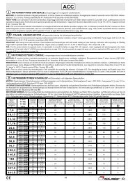
1.1 Basic Understanding of AC Servos<br />
To develop such a servo system, an automatic control system involving feedback control 1<br />
must be designed. This automatic control system can be illustrated in the following block<br />
diagram:<br />
Configuration of Servo System<br />
Specified position +<br />
input<br />
-<br />
Servo<br />
amplifier<br />
Servomotor<br />
Controlled<br />
machine<br />
(load)<br />
Machine position<br />
output<br />
Feedback part<br />
1<br />
Detector<br />
This servo system is an automatic control system that detects the machine position (output<br />
data), feeds back the data to the input side, compares it with the specified position (input<br />
data), and moves the machine by the difference between the compared data.<br />
In other words, the servo system is a system to control the output data to match the specified<br />
input data.<br />
If, for example, the specified position changes, the servo system will reflect the changes.<br />
In the above example, input data is defined as a position, but input data can be any physical<br />
quantities such as orientation (angle), water pressure, or voltage.<br />
Position, speed, force (torque), electric current, and so on are typical controlled values for a<br />
servo system.<br />
TERMS<br />
1<br />
Feedback control<br />
A control method in which process variables are returned to the input side to form a closed loop. It is<br />
also called closed-loop control. If a negative signal is returned to the input side, it is called negative<br />
feedback control. Normally, negative feedback control is used to stabilize the system. If feedback is<br />
not returned, the control method is called open-loop control.<br />
1-3
WARNING<br />
May cause<br />
electric shock.<br />
Disconnect all power<br />
and wait 5 min.<br />
before servicing.<br />
Use proper<br />
grounding techniques.<br />
CHARGE<br />
5<br />
!<br />
480<br />
V 460<br />
V<br />
440<br />
V<br />
400<br />
V 380<br />
V<br />
0<br />
V<br />
DUDVDWB1<br />
B2 DC<br />
24N<br />
DC<br />
24P<br />
- +1 +2 L1/R L2/S L3/T U V W<br />
O<br />
P<br />
E<br />
R<br />
A<br />
T<br />
O<br />
POWER<br />
R<br />
MOD E/<br />
SET DATA/<br />
CN3<br />
CN8<br />
CN5<br />
1 For First-time Users of AC Servos<br />
1.1.2 Technical Terms<br />
1.1.2 Technical Terms<br />
The main technical terms used in this manual are as follows:<br />
• Servo mechanism<br />
• Servo<br />
Normally, servo is synonymous with servo mechanism. However, because “mechanism”<br />
is omitted, the meaning becomes somewhat ambiguous. Servo may refer to the<br />
entire servo mechanism but may also refer to an integral part of a servo mechanism such<br />
as a servomotor or a servo amplifier. This manual also follows this convention in the use<br />
of the term “servo.”<br />
• Servo control system<br />
Servo control system is almost synonymous with servo mechanism but places the focus<br />
on system control. In this manual, the term “servo system” is also used as a synonym of<br />
servo control system.<br />
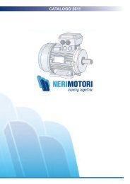
Related Terms<br />
Servomotor<br />
SERVOPACK<br />
Servodrive<br />
Servo system<br />
Meaning<br />
General servomotors or Yaskawa <strong>SGMBH</strong> servomotors. In some cases, a position<br />
detector (encoder) is included in a servomotor.<br />
Trademark of Yaskawa servo amplifier “<strong>SGDM</strong> and <strong>SGDH</strong> SERVOPACKs.”<br />
A servomotor and amplifier pair. Also called “servo.”<br />
A closed control system consisting of a host controller, servodrive and controlled<br />
system to form a servo mechanism.<br />
Host controller<br />
Reference<br />
SERVOPACK<br />
<strong>SGDH</strong><br />
-<br />
YASKAWA<br />
Amplifier<br />
(SERVOPACK)<br />
Servomotor<br />
Operate<br />
Controlled<br />
system<br />
Servodrive<br />
Servo system<br />
1-4
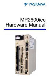
1.2 Configuration of Servo System<br />
1.2 Configuration of Servo System<br />
The following diagram illustrates a servo system in detail:<br />
Position or<br />
speed<br />
reference<br />
(Input)<br />
Comparator<br />
Power<br />
amplifier<br />
Host controller<br />
(5)<br />
Servo amplifier<br />
(4)<br />
Motor<br />
drive<br />
circuit<br />
(Output)<br />
Position<br />
Speed<br />
1<br />
Position or<br />
speed<br />
feedback<br />
(3) (2)<br />
Gear<br />
(1)<br />
Controlled<br />
system<br />
Movable table<br />
Ball screw<br />
Detector servomotor Drive system<br />
(1) Controlled<br />
system:<br />
Mechanical system for which the position or speed is to be controlled. This<br />
includes a drive system that transmits torque from a servomotor.<br />
(2) Servomotor: A main actuator that moves a controlled system. Two types are available: AC servomotor<br />
and DC servomotor.<br />
(3) Detector: A position or speed detector. Normally, an encoder mounted on a motor is used as<br />
a position detector.<br />
(4) Servo amplifier: An amplifier that processes an error signal to correct the difference between a reference<br />
and feedback data and operates the servomotor accordingly. A servo amplifier<br />
consists of a comparator, which processes error signals, and a power amplifier,<br />
which operates the servomotor.<br />
(5) Host controller: A device that controls a servo amplifier by specifying a position or speed as a set<br />
point.<br />
1-5
1 For First-time Users of AC Servos<br />
Servo components (1) to (5) are outlined below:<br />
1. Controlled System<br />
In the previous figure, the controlled system is a movable table for which the position or<br />
speed is controlled. The movable table is driven by a ball screw and is connected to the<br />
servomotor via gears. So, the drive system consists of:<br />
• Gears + Ball Screw<br />
This drive system is most commonly used because the power transmission ratio (gear<br />
ratio) can be freely set to ensure high positioning accuracy. However, play in the gears<br />
must be minimized.<br />
The following drive system 1 is also possible when the controlled system is a movable<br />
table:<br />
• Coupling + Ball Screw<br />
When the power transmission ratio is<br />
Rolling-contact<br />
1 : 1, a coupling is useful because it<br />
guide<br />
has no play.<br />
Coupling<br />
Ball screw Rolling-contact<br />
This drive system is widely used for<br />
bearing<br />
machining tools.<br />
Housing<br />
• Timing Belt + Trapezoidal Screw Thread<br />
A timing belt is a coupling device that allows<br />
the power transmission ratio to be set freely<br />
and that has no play.<br />
A trapezoidal screw thread does not provide<br />
excellent positioning accuracy, so can be<br />
treated as a minor coupling device.<br />
Trapezoidal<br />
screw thread<br />
To develop an excellent servo system, it is<br />
important to select a rigid drive system that<br />
has no play.<br />
Servomotor<br />
Timing belt<br />
Configure the controlled system by using an appropriate drive system for the control<br />
purpose.<br />
TERMS<br />
1<br />
Drive system<br />
Also called a drive mechanism. A drive system connects an actuator (such as a servomotor) to a controlled<br />
system and serves a mechanical control component that transmits torque to the controlled system,<br />
orientates the controlled system, and converts motion from rotation to linear motion and vice<br />
versa.<br />
1-6
1.2 Configuration of Servo System<br />
2. Servomotor<br />
• DC Servomotor and AC Servomotor<br />
Servomotors are divided into two types: DC servomotors and AC servomotors.<br />
DC servomotors are driven by direct current (DC). They have a long history. Up until<br />
the 1980s, the term “servomotor” used to imply a DC servomotor.<br />
From 1984, AC servomotors were emerging as a result of rapid progress in microprocessor<br />
technology. Driven by alternating current (AC), AC servomotors are now widely<br />
used because of the following advantages:<br />
• Easy maintenance: No brush<br />
• High speed: No limitation in rectification rate<br />
Note however that servomotors and the SERVOPACKs use some parts that are subject<br />
to mechanical wear or aging. For preventive maintenance, inspect and replace parts at<br />
regular intervals. For details, refer to Chapter 8 Inspection, Maintenance, and Troubleshooting.<br />
• AC Servomotor<br />
AC servomotors are divided into two types: Synchronous type and induction type. The<br />
synchronous type is more commonly used.<br />
For a synchronous type servomotor, motor speed is controlled by changing the frequency<br />
of alternating current.<br />
A synchronous type servomotor provides strong holding torque when stopped, so this<br />
type is ideal when precise positioning is required. Use this type for a servo mechanism<br />
for position control.<br />
The following figure illustrates the structure of a synchronous type servomotor:<br />
Light-receiving<br />
element<br />
Rotary disc<br />
Light-emitting<br />
element<br />
Armature<br />
wire Housing Front cap<br />
Stator core<br />
Ball bearing<br />
1<br />
Shaft<br />
Rotor core<br />
Position detector<br />
(encoder)<br />
Lead wire<br />
Magnet<br />
Yaskawa <strong>SGMBH</strong> servomotors are of the synchronous type.<br />
• Performance of Servomotor<br />
A servomotor must have “instantaneous power” so that it can start as soon as a start reference<br />
is received. The term “power rating (kW/s)” is used to represent instantaneous<br />
power. It refers to the electric power (kW) that a servomotor generates per second. The<br />
greater the power rating, the more powerful the servomotor.<br />
1-7
1 For First-time Users of AC Servos<br />
3. Detector<br />
A servo system requires a position or speed detector. It uses an encoder mounted on a<br />
servomotor for this purpose. Encoders are divided into the following two types:<br />
• Incremental Encoder<br />
An incremental encoder is a pulse generator, which generates a certain number of pulses<br />
per revolution (e.g., 2,000 pulses per revolution). If this encoder is connected to the<br />
mechanical system and one pulse is defined as a certain length (e.g., 0.001 mm), it can<br />
be used as a position detector. However, this encoder does not detect an absolute position<br />
and merely outputs a pulse train. Hence zero point return operation must be performed<br />
before positioning. The following figure illustrates the operation principle of a<br />
pulse generator:<br />
Center of<br />
revolution<br />
Phase A<br />
Phase B<br />
Phase Z<br />
Rotary<br />
disc<br />
Slit<br />
Light-emitting<br />
element<br />
Phase A pulse train<br />
Phase B pulse train<br />
Fixed slit<br />
Light-receiving<br />
element<br />
Rotary slit<br />
• Absolute Encoder<br />
An absolute encoder is designed to detect an absolute angle of rotation as well as to perform<br />
the general functions of an incremental encoder. With an absolute encoder, therefore,<br />
it is possible to create a system that does not require zero point return operation at<br />
the beginning of each operation.<br />
• Difference between an Absolute and Incremental Encoder<br />
An absolute encoder will keep track of the motor shaft position even if system power is<br />
lost and some motion occurs during that period of time. The incremental encoder is<br />
incapable of the above.<br />
1-8
1.2 Configuration of Servo System<br />
4. Servo Amplifier<br />
A servo amplifier is required to operate an AC servomotor. The following figure illustrates<br />
the configuration of a servo amplifier:<br />
Servo amplifier<br />
Comparator Power<br />
amplifier<br />
Motor driving AC power<br />
Reference<br />
input<br />
1<br />
Feedback<br />
Servomotor<br />
Commercial AC power<br />
A servo amplifier consists of the following two sections:<br />
• Comparator<br />
A comparator consists of a comparison function and a control function. The comparison<br />
function compares reference input (position or speed) with a feedback signal and generates<br />
a differential signal.<br />
The control function amplifies and transforms the differential signal. In other words, it<br />
performs proportional (P) control or proportional/integral (PI) control 1 . (It is not important<br />
if you do not understand these control terms completely at this point.)<br />
• Power Amplifier<br />
A power amplifier runs the servomotor at a speed or torque proportional to the output of<br />
the comparator. In other words, from the commercial power supply of 50/60 Hz, it generates<br />
alternating current with a frequency proportional to the reference speed and runs<br />
the servomotor with this current.<br />
5. Host Controller<br />
A host controller controls a servo amplifier by specifying a position or speed as a set<br />
point.<br />
For speed reference, a position control loop may be formed in the host controller when a<br />
position feedback signal is received. Yaskawa machine controller MP920 is a typical<br />
host controller.<br />
TERMS<br />
1 Proportional/integral (PI) control<br />
PI control provides more accurate position or speed control than proportional control, which is more<br />
commonly used.<br />
1-9
WARNING<br />
May cause<br />
electric shock.<br />
Disconnect all power<br />
and wait 5 min.<br />
before servicing.<br />
Use proper<br />
grounding techniques.<br />
5<br />
1 For First-time Users of AC Servos<br />
1.3.1 Outline<br />
1.3 Features of Σ-ΙΙ <strong>Series</strong> Servos<br />
1.3.1 Outline<br />
A Σ-ΙΙ <strong>Series</strong> Servo consists of an <strong>SGMBH</strong> servomotor and an <strong>SGDM</strong> SERVOPACK or an<br />
<strong>SGDH</strong> SERVOPACK.<br />
This section outlines <strong>SGMBH</strong> servomotor types and the control types of <strong>SGDM</strong> and <strong>SGDH</strong><br />
SERVOPACKs.<br />
• <strong>SGMBH</strong> Servomotor Type<br />
Σ-ΙΙ <strong>Series</strong> <strong>SGMBH</strong> servomotors are synchronous type servomotors<br />
and have the following features:<br />
Rated Motor<br />
Speed<br />
Maximum<br />
Motor Speed<br />
Voltage<br />
Maximum<br />
Torque<br />
Rated Output<br />
1500 min -1 400 V 200 % 22 to 55 kW<br />
2000 min -1 200 V 22 to 37 kW<br />
<strong>SGMBH</strong><br />
Servomotor<br />
• Control Types of <strong>SGDM</strong> and <strong>SGDH</strong> SERVOPACKs<br />
The <strong>SGDM</strong> and <strong>SGDH</strong> SERVOPACKs allow the control of speed, position and torque.<br />
Speed Control (Analog Reference)<br />
Accepts an analog voltage speed reference.<br />
Position Control (Pulse Reference)<br />
Accepts a pulse train position reference.<br />
Torque Control (Analog Reference)<br />
<strong>SGDM</strong> or <strong>SGDH</strong> SERVOPACK<br />
Accepts an analog voltage torque reference.<br />
1-10
1.3 Features of Σ-ΙΙ <strong>Series</strong> Servos<br />
1.3.2 Using the <strong>SGDM</strong> and <strong>SGDH</strong> SERVOPACK<br />
• Using the SERVOPACK for Speed Control<br />
The most common use of a SERVOPACK for speed control is shown below:<br />
Host controller<br />
Position reference +<br />
-<br />
Position control loop<br />
1<br />
Position<br />
feedback<br />
(Analog<br />
voltage)<br />
Speed<br />
reference<br />
+<br />
-<br />
+<br />
SERVOPACK<br />
(speed control mode)<br />
Power<br />
amplifier<br />
Position Speed<br />
Convert<br />
Pulse train<br />
-<br />
Torque<br />
(current)<br />
feedback<br />
Servomotor<br />
Position feedback<br />
Encoder<br />
As shown in the above figure, a position control loop is formed in the host controller. The<br />
host controller compares a position reference with a position feedback signal and sends the<br />
processed result to the SERVOPACK as a speed reference.<br />
In this way the host controller can be freed from performing the servo mechanism control.<br />
The SERVOPACK undertakes the speed control loop and subsequent control processing.<br />
A machine controller from Yaskawa’s MP900/MP2000 series is an example of a typical host<br />
controller.<br />
1-11
1 For First-time Users of AC Servos<br />
1.3.2 Using the <strong>SGDM</strong> and <strong>SGDH</strong> SERVOPACK<br />
• Using the SERVOPACK for Torque Control<br />
The SERVOPACK can be used for torque control as shown below.<br />
Host controller<br />
Position<br />
monitoring<br />
Position<br />
information<br />
Torque<br />
reference<br />
SERVOPACK<br />
(torque control mode)<br />
Power<br />
amplifier<br />
Servomotor<br />
(Analog<br />
voltage)<br />
Torque (current)<br />
feedback<br />
Pulse train<br />
Position feedback<br />
Encoder<br />
The host controller outputs a torque reference to control the SERVOPACK. It also receives a<br />
pulse train (position information) from the SERVOPACK and uses it to monitor the position.<br />
1-12
1.3 Features of Σ-ΙΙ <strong>Series</strong> Servos<br />
• Using the SERVOPACK for Position Control<br />
The SERVOPACK can be used for position control as shown below.<br />
Host controller<br />
Position<br />
monitoring<br />
Position<br />
information<br />
Position<br />
reference<br />
Pulse<br />
train<br />
+ +<br />
- -<br />
Speed/current loop<br />
SERVOPACK<br />
(position control mode)<br />
Power<br />
amplifier<br />
Servomotor<br />
1<br />
Pulse train<br />
Position feedback<br />
Encoder<br />
The host controller can send a position reference (pulse train) to the SERVOPACK to perform<br />
positioning or interpolation. This type of the SERVOPACK contains a position control<br />
loop.<br />
Parameters can be used to select either of the following pulse trains:<br />
• Sign + pulse train<br />
• Two-phase pulse train with 90° phase difference<br />
• Forward and reverse pulse trains<br />
The host controller receives a pulse train (position information) from the SERVOPACK and<br />
uses it to monitor the position.<br />
• Parameter Setting<br />
A Digital Operator can be used to set parameters for a SERVOPACK as follows:<br />
• Setting parameters to enable or disable each function<br />
• Setting parameters required for functions to be used<br />
Set parameters according to the servo system to be set up.<br />
1-13
2<br />
Basic Operation<br />
2<br />
This chapter describes the first things to do when Σ-<strong>II</strong> <strong>Series</strong> products are<br />
delivered. It also explains the most fundamental ways of connecting and operating<br />
Σ-<strong>II</strong> <strong>Series</strong> products. Both first-time and experienced servo users must<br />
read this chapter.<br />
2.1 Precautions - - - - - - - - - - - - - - - - - - - - - - - - - - - - - - - - - - - 2-2<br />
2.2 Installation - - - - - - - - - - - - - - - - - - - - - - - - - - - - - - - - - - - - 2-5<br />
2.2.1 Checking on Delivery - - - - - - - - - - - - - - - - - - - - - - - - - - - - - - - - - - - 2-5<br />
2.2.2 Installing the Servomotor - - - - - - - - - - - - - - - - - - - - - - - - - - - - - - - - 2-7<br />
2.2.3 Allowable Radial and Thrust Loads - - - - - - - - - - - - - - - - - - - - - - - - 2-11<br />
2.2.4 Installing the SERVOPACK - - - - - - - - - - - - - - - - - - - - - - - - - - - - - - 2-11<br />
2.2.5 Power Loss - - - - - - - - - - - - - - - - - - - - - - - - - - - - - - - - - - - - - - - - - 2-14<br />
2.3 Connection and Wiring - - - - - - - - - - - - - - - - - - - - - - - - - - 2-15<br />
2.3.1 Connecting to Peripheral Devices - - - - - - - - - - - - - - - - - - - - - - - - - 2-16<br />
2.3.2 Main Circuit Wiring and Power ON Sequence - - - - - - - - - - - - - - - - - 2-20<br />
2.4 I/O Signals - - - - - - - - - - - - - - - - - - - - - - - - - - - - - - - - - - - 2-26<br />
2.4.1 Examples of I/O Signal Connections - - - - - - - - - - - - - - - - - - - - - - - 2-27<br />
2.4.2 List of CN1 Terminals - - - - - - - - - - - - - - - - - - - - - - - - - - - - - - - - - - 2-28<br />
2.4.3 I/O Signal Names and Functions - - - - - - - - - - - - - - - - - - - - - - - - - - 2-29<br />
2.4.4 Interface Circuits - - - - - - - - - - - - - - - - - - - - - - - - - - - - - - - - - - - - - 2-31<br />
2.5 Wiring Encoders - - - - - - - - - - - - - - - - - - - - - - - - - - - - - - - 2-35<br />
2.5.1 Connecting an Encoder (CN2) and Output Signals<br />
from the SERVOPACK (CN1) - - - - - - - - - - - - - - - - - - - - - - - - - - - - 2-35<br />
2.5.2 Terminal Layout and Types of CN2 Encoder Connector - - - - - - - - - - 2-36<br />
2.5.3 Examples of Connecting I/O Signal Terminals - - - - - - - - - - - - - - - - 2-37<br />
2-1
WARNING<br />
5<br />
!<br />
May cause<br />
electric shock.<br />
Disconnect all power<br />
and wait 5 min.<br />
before servicing.<br />
Use proper<br />
grounding techniques.<br />
480<br />
V 460<br />
V<br />
440<br />
V<br />
400<br />
V 380<br />
V<br />
0<br />
V<br />
DUDVDWB1<br />
B2 DC<br />
24N<br />
DC<br />
24P<br />
POWER<br />
R<br />
MOD E/<br />
SET DATA/<br />
CN3<br />
GDH<br />
- +1 +2 L1/R L2/S L3/T U V W<br />
CN8<br />
CN5<br />
2 Basic Operation<br />
2.1 Precautions<br />
This section provides notes on using Σ-<strong>II</strong> <strong>Series</strong> products.<br />
• Use a 200-VAC or a 400-VAC power supply.<br />
Use a 200-VAC or a 400-VAC power supply. The voltage of the power supply depends on<br />
your SERVOPACK model. For more information, refer to 7.3 SERVOPACK Ratings and<br />
Specifications.<br />
• Do not connect the servomotor directly to a commercial power line.<br />
Direct connection to the power frequency supply<br />
will damage the servomotor. The servomotor<br />
cannot be operated without an <strong>SGDM</strong> or an<br />
<strong>SGDH</strong> SERVOPACK.<br />
400 VAC<br />
power supply<br />
Direct<br />
connection<br />
Damage will result!<br />
• Do not change wiring when power is ON.<br />
Always turn the power OFF before connecting<br />
or disconnecting a connector. (Except for Digital<br />
Operator (Model: JUSP-OP02A-2))<br />
O<br />
P<br />
E<br />
R<br />
A<br />
T<br />
O<br />
OFF<br />
(POWER and<br />
CHANGE lamp)<br />
SERVOPACK<br />
S -<br />
YASKAWA<br />
CHARGE<br />
Always turn the<br />
power OFF before<br />
connecting a<br />
connector.<br />
• Before inspecting, always wait 5 minutes after turning power OFF.<br />
Even after the power is turned OFF, residual<br />
electric charge still remains in the capacitor<br />
inside the SERVOPACK. To prevent an electric<br />
shock, always wait for the CHARGE lamp to go<br />
OFF before starting inspection (if necessary).<br />
CHARGE lamp<br />
2-2
WARNING<br />
5<br />
!<br />
May cause<br />
electric shock.<br />
Disconnect all power<br />
and wait 5 min.<br />
before servicing.<br />
Use proper<br />
grounding techniques.<br />
480<br />
V 460<br />
V<br />
440<br />
V<br />
400<br />
V 380<br />
V<br />
0<br />
V<br />
DUDVDWB1<br />
B2 DC<br />
24N<br />
DC<br />
24P<br />
- +1 +2 L1/R L2/S L3/T U V W<br />
480<br />
V 460<br />
V<br />
440<br />
V<br />
400<br />
V 380<br />
V<br />
0<br />
V<br />
DUDVDWB1<br />
B2 DC<br />
24N<br />
DC<br />
24P<br />
POWER<br />
R<br />
MOD E/<br />
SET DATA/<br />
CN3<br />
SERVOPACK<br />
GDH<br />
YASKAWA<br />
- +1 L1/R L2/S L3/T U V W<br />
CN8<br />
CN5<br />
WARNING<br />
5<br />
!<br />
May cause<br />
electric shock.<br />
Disconnect all power<br />
and wait 5 min.<br />
before servicing.<br />
Use proper<br />
grounding techniques.<br />
480<br />
V 460<br />
V<br />
440<br />
V<br />
400<br />
V 380<br />
V<br />
0<br />
V<br />
DUDVDWB1<br />
B2 DC<br />
24N<br />
DC<br />
24P<br />
POWER<br />
R<br />
MOD E/<br />
SET DATA/<br />
CN3<br />
SERVOPACK<br />
GDH<br />
YASKAWA<br />
- +1 +2 L1/R L2/S L3/T U V W<br />
CN8<br />
CN5<br />
2.1 Precautions<br />
• Always follow the specified installation method.<br />
When installing SERVOPACKs side by side as<br />
shown in the figure on the right, allow at least 10<br />
mm (0.39 in) between and at least 50 mm (1.97 in)<br />
above and below each SERVOPACK. The<br />
SERVOPACK generates heat. Install the<br />
SERVOPACK so that it can radiate heat freely. Note<br />
also that the SERVOPACK must be in an environment<br />
free from condensation, vibration and shock.<br />
50 mm<br />
or more<br />
• Perform noise reduction and grounding properly.<br />
If the signal line is noisy, vibration or malfunction will result.<br />
Provide sufficient clearance<br />
CHARGE<br />
+2<br />
CHARGE S -<br />
Ambient temperature: 0 to 55°C<br />
O<br />
P<br />
E<br />
R<br />
A<br />
T<br />
O<br />
10 mm<br />
or more<br />
CHARGE<br />
S -<br />
O<br />
P<br />
E<br />
R<br />
A<br />
T<br />
O<br />
2<br />
• Separate high-voltage cables from low-voltage<br />
cables.<br />
• Use cables as short as possible.<br />
• Perform the grounding with the ground resistance<br />
of 100 Ω or less for the servomotor and<br />
the SERVOPACK.<br />
• Never use a line filter for the power supply in<br />
the motor circuit.<br />
Casing<br />
SERVOPACK<br />
Signal<br />
line<br />
Servomotor<br />
M<br />
Ground<br />
(with resistance<br />
of 100 Ω or less)<br />
• Conduct a voltage resistance test under the following conditions.<br />
• Voltage: 1500 Vrms AC, one minute<br />
• Current limit: 100 mA<br />
• Frequency: 50/60 Hz<br />
• Voltage application points: For the 200-V series, between the frame ground and the point<br />
where the L1C/r, L3C/t, L1/R, L2/S, and L3/T terminals are all connected. For the 400-<br />
V series, between the frame ground and the point where the 480 V, 460 V, 440 V, 400 V,<br />
380 V, 0 V, L1/R, L2/S, and L3/T terminals are all connected.<br />
Contact your Yaskawa representative before applying voltage to points not specified above<br />
when performing standards certification tests or such.<br />
• Use a fast-response type ground-fault interrupter.<br />
For a ground-fault interrupter, always use a<br />
fast-response type or one designed for PWM<br />
inverters. Do not use a time-delay type.<br />
Correct<br />
Fast-response<br />
type<br />
Ground-fault interrupter<br />
Correct<br />
For PWM<br />
inverter<br />
Incorrect<br />
Time-delay<br />
type<br />
2-3
2 Basic Operation<br />
• Do not perform continuous operation under overhanging load.<br />
Continuous operation cannot be performed<br />
by rotating the motor from the load and<br />
applying regenerative braking. Regenerative<br />
braking by the SERVOPACK can be applied<br />
only for a short period, such as the motor<br />
deceleration time.<br />
Servomotor<br />
Do not apply regenerative<br />
braking continuously.<br />
• The servomotor cannot be operated by turning the power ON and<br />
OFF.<br />
Frequently turning the power ON and OFF<br />
causes the internal circuit elements to deteriorate.<br />
Always start or stop the servomotor by<br />
using reference pulses.<br />
For three-phase 200 VAC<br />
Power<br />
supply<br />
SERVOPACK<br />
200 to 230 V<br />
L1C/r<br />
L3C/t<br />
L1/R<br />
L2/S<br />
L3/T<br />
For three-phase 400 VAC<br />
Power<br />
supply<br />
Do not start or stop by<br />
tuning power ON and OFF.<br />
SERVOPACK<br />
380 to 480 V<br />
0V<br />
L1/R<br />
L2/S<br />
L3/T<br />
2-4
2.2 Installation<br />
2.2 Installation<br />
This section describes how to check Σ-<strong>II</strong> <strong>Series</strong> products on delivery and how to install them.<br />
2.2.1 Checking on Delivery<br />
Check the following items when Σ-<strong>II</strong> <strong>Series</strong> products are delivered.<br />
Check Items<br />
Are the delivered products the ones<br />
that were ordered?<br />
Does the servomotor shaft rotate<br />
smoothly?<br />
Is there any damage?<br />
Are there any loose screws?<br />
Comments<br />
Check the model numbers marked on the nameplates of the servomotor<br />
and the SERVOPACK. (See the following.)<br />
The servomotor shaft is normal if it can be turned smoothly by<br />
hand. Servomotors with brakes, however, cannot be turned manually.<br />
Check the overall appearance, and check for damage or scratches<br />
that may have occurred during shipping.<br />
Check screws for looseness using a screwdriver.<br />
2<br />
If any of the above items are faulty or incorrect, contact your Yaskawa sales representative<br />
or the dealer from whom you purchased the products.<br />
• Servomotors<br />
External Appearance and Nameplate Examples<br />
(Example)<br />
Rated output<br />
Servomotor model<br />
AC SERVO MOTOR<br />
TYPE<br />
kw<br />
-1 min<br />
RATING<br />
<strong>SGMBH</strong> - 2BDCA<br />
22 N. m<br />
140<br />
1500<br />
A<br />
58<br />
CONT.<br />
ENCODER<br />
UTMAH-B12BDYR11<br />
17 bit<br />
<strong>SGMBH</strong><br />
servomotor<br />
SER.NO.<br />
DATE<br />
K7A500 101 - 004<br />
9708<br />
YASKAWA ELECTRIC CORPORATION<br />
JAPAN<br />
Munufacturing date<br />
Serial number<br />
Rated rotation speed<br />
2-5
WARNING<br />
May cause<br />
electric shock.<br />
Disconnect all power<br />
and wait 5 min.<br />
before servicing.<br />
Use proper<br />
grounding techniques.<br />
CHARGE<br />
5<br />
!<br />
480<br />
V<br />
440<br />
V<br />
400380<br />
V V<br />
DC DC<br />
24N 24P<br />
O<br />
P<br />
E<br />
R<br />
A<br />
T<br />
O<br />
R<br />
CN3<br />
POWER<br />
MOD E/<br />
SET DATA/<br />
CN8<br />
CN5<br />
2 Basic Operation<br />
2.2.1 Checking on Delivery<br />
Model Numbers<br />
<strong>SGMBH</strong> -2BD C A <br />
Σ-<strong>II</strong> <strong>Series</strong><br />
Servomotor<br />
Servomotor Capacity<br />
2B: 22 kW 4E: 45 kW (400 V only)<br />
3Z: 30 kW 5E: 55 kW (400 V only)<br />
3G: 37 kW<br />
Supply Voltage<br />
A: 200 V<br />
D: 400 V<br />
Encoder Specifications<br />
2: 17-bit absolute encoder<br />
3: 20-bit absolute encoder (optional)<br />
C: 17-bit incremental encoder<br />
Options<br />
1: With V-type oil seal<br />
B: With V-type oil seal, 90-VDC holding brake<br />
C: With V-type oil seal, 24-VDC holding brake<br />
S: With S-type oil seal<br />
D: With S-type oil seal, 90-VDC holding brake<br />
E: With S-type oil seal, 24-VDC holding brake<br />
Shaft End Specifications<br />
2: Flange mounted, straight without key<br />
6: Flange mounted, straight with key and tap<br />
K: With foot, straight without key<br />
L: With foot, straight with key and tap<br />
Design Revision Order<br />
A: Maximum torque 200%<br />
• SERVOPACKs<br />
External Appearance and Nameplate<br />
SERVOPACK<br />
<strong>SGDH</strong><br />
-<br />
YASKAWA<br />
(Example)<br />
SERVOPACK model<br />
SERVOPACK<br />
MODEL <strong>SGDH</strong> - 3ZDE<br />
AC-INPUT AC-OUTPUT<br />
VOLTS 380-480<br />
Hz 50/60<br />
VOLTS 0 - 480<br />
PHASE 3<br />
PHASE 3 AMPS 175<br />
AMPS 145 kW (HP) 30.0 (40.2)<br />
S / N R7C303 - 221 - 4<br />
YASKAWA ELECTRIC<br />
MADE IN JAPAN<br />
V 460<br />
V 0<br />
DUDVDWB1<br />
B2<br />
- +1 +2 L1/R L2/S L3/T U V W<br />
Σ-<strong>II</strong> <strong>Series</strong> <strong>SGDM</strong> and <strong>SGDH</strong><br />
SERVOPACKs<br />
Serial number Output power<br />
Applicable power supply<br />
2-6
2.2 Installation<br />
<strong>SGDM</strong> Model Numbers<br />
<strong>SGDM</strong> -2BA D A<br />
Σ-<strong>II</strong> <strong>Series</strong><br />
<strong>SGDM</strong> SERVOPACK<br />
Rated Output (motor capacity)<br />
2B: 22 kW<br />
3Z: 30 kW<br />
3G: 37 kW<br />
Supply Voltage<br />
A: 200 V<br />
Model<br />
D: For torque, speed, and position control<br />
2<br />
Design revision order<br />
<strong>SGDH</strong> Model Numbers<br />
<strong>SGDH</strong> -2BD E<br />
Σ-<strong>II</strong> <strong>Series</strong><br />
<strong>SGDH</strong> SERVOPACK<br />
Rated Output (motor capacity)<br />
2B: 22 kW 4E: 45 kW (400 V only)<br />
3Z: 30 kW 5E: 55 kW (400 V only)<br />
3G: 37 kW<br />
Supply Voltage<br />
A: 200 V<br />
D: 400 V<br />
Model<br />
E: For torque, speed, and position control<br />
2.2.2 Installing the Servomotor<br />
<strong>SGMBH</strong> servomotors can be installed either horizontally or vertically. The service life of the<br />
servomotor will be shortened or unexpected problems will occur if the servomotor is<br />
installed incorrectly or in an inappropriate location. Always observe the following installation<br />
instructions.<br />
• Prior to Installation<br />
The end of the motor shaft is coated with anticorrosive paint. Thoroughly remove the paint<br />
using a cloth moistened with thinner prior to installation.<br />
Anticorrosive paint is<br />
coated here.<br />
2-7
2 Basic Operation<br />
2.2.2 Installing the Servomotor<br />
IMPORTANT<br />
Avoid getting thinner on other parts of the servomotor when cleaning the shaft.<br />
• Storage Temperature<br />
Store the servomotor within the following temperature range if it is stored with the power<br />
cable disconnected.<br />
Between -20 to 60 °C.<br />
• Installation Site<br />
<strong>SGMBH</strong> servomotors are designed for indoor use. Install the servomotor in environments<br />
that satisfy the following conditions.<br />
• Free of corrosive or explosive gases.<br />
• Well-ventilated and free of dust and moisture.<br />
• Ambient temperature of 0 to 40 °C.<br />
• Relative humidity of 20% to 80% (non-condensing)<br />
• Facilitates inspection and cleaning.<br />
• Altitude : 1000 m max.<br />
Install a protective cover over the servomotor if it is used in a location that is subject to<br />
water or oil mist. Also use a servomotor with an oil seal to seal the through shaft 1 section.<br />
Install the electrical connector with the cable facing downward or in a horizontal position.<br />
• Alignment<br />
Align the shaft of the servomotor with that of the equipment to be controlled, then connect<br />
the shafts with flexible couplings. Install the servomotor so that alignment accuracy falls<br />
within the following range.<br />
Measure this distance at four different positions in the circumference.<br />
The difference between the maximum and minimum measurements<br />
must be 0.03 mm or less. (Turn together with couplings)<br />
Measure this distance at four different positions in the<br />
circumference. The difference between the maximum<br />
and minimum measurementsmust be 0.03 mm or less.<br />
(Turn together with couplings)<br />
TERMS<br />
1<br />
Through Sections of the shaft<br />
This refers to the gap where the shaft protrudes from the end of<br />
the motor.<br />
Shaft<br />
opening<br />
2-8
2.2 Installation<br />
IMPORTANT<br />
1. Vibration that will damage the bearings will occur if the shafts are not properly aligned.<br />
2. Do not allow direct impact to be applied to the shafts when installing the coupling. Otherwise the<br />
encoder mounted on the opposite end of the shaft may be damaged.<br />
3. Before mounting the pinion gear directly to the motor output shaft, consult your Yaskawa sales representative.<br />
• Wiring the Servomotor Power Lines<br />
Connect the servomotor power lines (U, V, and W) to the servomotor terminal block (M10)<br />
in the servomotor terminal box. Connect the ground wire to the ground screw in the terminal<br />
box.<br />
2<br />
• Wiring the Servomotor Thermostat<br />
The servomotor has a built-in thermostat. Wire the thermostat leads (l, lb) to the terminal<br />
block (M4) in the servomotor’s terminal box.<br />
• Wiring the Servomotor Fan<br />
Wire the servomotor fan leads U(A), V(B), and W(C) so that the direction of air flows<br />
according to the following diagram. If the air flows in the opposite direction, change the wiring<br />
of any of the two phases U, V, and W.<br />
Direction of<br />
cool air<br />
Servomotor<br />
• Protecting the Servomotor Fan<br />
The servomotor fan has a built-in thermal protector, as shown in the following diagram, that<br />
operates at 140°C ±5 %. To protect the servomotor fan from overcurrent, use with a 2-A nofuse<br />
breaker.<br />
U<br />
V<br />
W<br />
2-9
2 Basic Operation<br />
2.2.2 Installing the Servomotor<br />
• Installing the Servomotor Fan<br />
To maximize the cooling capacity of the servomotor fan, install the fan at least 200 mm<br />
(7.87 in) from the inlet side of the servomotor as shown in the following diagram.<br />
Cool air<br />
Servomotor<br />
200 mm min.<br />
• Servomotor Connector Specifications<br />
• Encoder Connector at Servomotor<br />
The connector specifications for the encoder on the servomotor are as follows:<br />
Encoder Connectors<br />
Plug Cable Clamp Receptacle *1<br />
L-shaped<br />
Straight<br />
JA08A-20-29S-JA-EB *2, *3<br />
or<br />
MS3108B20-29S<br />
JA06A-20-29S-J1-EB *2, *3<br />
or<br />
MS3106B20-29S<br />
JL04-2022CKE (**) *2, *3<br />
or<br />
MS3057-12A<br />
** indicates the cable diameter.<br />
97F-3102E20-29P *3<br />
* 1. Connector at servomotor is already provided.<br />
* 2. Manufactured by Japan Aviation Electronics Industry, Ltd.<br />
* 3. Waterproof.<br />
• Fan Connector on Servomotor<br />
L-shaped<br />
CE05-8A18-10SD-B-BAS *2, *3<br />
or<br />
MS3108B18-10S<br />
To be prepared by the customer<br />
The connector specifications for the fan on the servomotor are as follows:<br />
Fan Connectors<br />
Plug Cable Clamp Receptacle *1<br />
Straight<br />
CE05-6A18-10SD-B-BSS *2, *3<br />
or<br />
MS3106B18-10S<br />
CE3057-10A-* (D265) *2, *3<br />
or<br />
MS3057-10A<br />
** indicates the cable diameter.<br />
CE05-2A18-10PD-B *3<br />
To be prepared by the customer<br />
* 1. Connector at servomotor is already provided.<br />
* 2. Manufactured by Daiichi Denshi Kogyo Co., Ltd.<br />
* 3. Waterproof.<br />
2-10
WARNING<br />
May cause<br />
electric shock.<br />
Disconnect all power<br />
and wait 5 min.<br />
before servicing.<br />
Use proper<br />
grounding techniques.<br />
5<br />
2.2 Installation<br />
2.2.3 Allowable Radial and Thrust Loads<br />
Design the mechanical system so radial and thrust loads 1 applied to the servomotor shaft end<br />
during operation falls within the ranges shown in the following table.<br />
Servomotor Model<br />
<strong>SGMBH</strong>-<br />
Allowable Radial Load<br />
Fr [N]<br />
Allowable Thrust Load<br />
Fs [N]<br />
LR<br />
[mm]<br />
2BA, 2BD 5880 2156 100<br />
3ZA, 3ZD 6272 2156 100<br />
3GA, 3GD 7448 2156 100<br />
4ED 7840 2156 100<br />
5ED 8428 2156 110<br />
2<br />
Note: Allowable radial and thrust loads shown above are the maximum values<br />
that could be applied to the shaft end from motor torque or other<br />
loads.<br />
LR<br />
Fr<br />
Fs<br />
2.2.4 Installing the SERVOPACK<br />
The <strong>SGDM</strong> and <strong>SGDH</strong> SERVOPACKs are the base-mounting servo controllers. Incorrect<br />
installation will cause problems. Always observe the installation instructions below.<br />
• Storage Temperature<br />
Store the servomotor within the following temperature range<br />
if it is stored with the power cable disconnected.<br />
Between -20 to +85 °C.<br />
<strong>SGDM</strong> and <strong>SGDH</strong> SERVOPACK<br />
TERMS<br />
1 Radial and thrust loads<br />
Thrust load (Fs): Load applied parallel to the centerline of the shaft.<br />
Radial load (Fr): Load applied perpendicular to the centerline of<br />
the shaft.<br />
Motor<br />
Fr<br />
Fs<br />
2-11
WARNING<br />
May cause<br />
electric shock.<br />
Disconnect all power<br />
and wait 5 min.<br />
before servicing.<br />
Use proper<br />
grounding techniques.<br />
CHARGE<br />
5<br />
!<br />
480<br />
V 460<br />
V<br />
440<br />
V<br />
400<br />
V 380<br />
V<br />
0<br />
V<br />
DC DC<br />
24N 24P<br />
O<br />
P<br />
E<br />
R<br />
A<br />
T<br />
O<br />
R<br />
CN3<br />
POWER<br />
MOD E/<br />
SET DATA/<br />
CN8<br />
CN5<br />
2 Basic Operation<br />
2.2.4 Installing the SERVOPACK<br />
• Installation Site<br />
Take the following precautions at the installation site.<br />
Situation<br />
Installation in a Control Panel<br />
Installation Near a Heating Unit<br />
Installation Near a Source of Vibration<br />
Installation at a Site Exposed to Corrosive<br />
Gas<br />
Other Situations<br />
Notes on Installation<br />
Design the control panel size, unit layout, and cooling method<br />
so the temperature around the SERVOPACK does not exceed<br />
55°C.<br />
Minimize heat radiated from the heating unit as well as any temperature<br />
rise caused by natural convection so the temperature<br />
around the SERVOPACK does not exceed 55°C.<br />
Install a vibration isolator beneath the SERVOPACK to avoid<br />
subjecting it to vibration.<br />
Take appropriate action to avoid corrosive gas. Corrosive gas<br />
does not have an immediate effect on the SERVOPACK, but<br />
will eventually cause electronic components and contactorrelated<br />
devices to malfunction.<br />
Do not install the SERVOPACK in hot and humid locations or<br />
locations subject to excessive dust or iron powder in the air.<br />
• Orientation<br />
Install the SERVOPACK perpendicular to the wall as shown in the figure.<br />
50 mm min.<br />
(ventilation exhaust)<br />
DUDVDWB1<br />
B2<br />
- +1 +2 L1/R L2/S L3/T U V W<br />
50 mm min.<br />
SERVOPACK<br />
<strong>SGDH</strong><br />
-<br />
YASKAWA<br />
50 mm min.<br />
50 mm min. (ventilation intake)<br />
120 mm min. 120 mm min.<br />
Air flow<br />
Air flow<br />
2-12
WARNING<br />
5<br />
May cause<br />
electric shock.<br />
Disconnect all power<br />
and wait 5 min.<br />
before servicing.<br />
Use proper<br />
grounding techniques.<br />
WARNING<br />
5<br />
May cause<br />
electric shock.<br />
Disconnect all power<br />
and wait 5 min.<br />
before servicing.<br />
Use proper<br />
grounding techniques.<br />
WARNING<br />
5<br />
May cause<br />
electric shock.<br />
Disconnect all power<br />
and wait 5 min.<br />
before servicing.<br />
Use proper<br />
grounding techniques.<br />
WARNING<br />
5<br />
May cause<br />
electric shock.<br />
Disconnect all power<br />
and wait 5 min.<br />
before servicing.<br />
Use proper<br />
grounding techniques.<br />
2.2 Installation<br />
• Installation<br />
Follow the procedure below to install multiple SERVOPACKs side by side in a control<br />
panel.<br />
Fan<br />
Fan<br />
50 mm<br />
or more<br />
30 mm or more 10 mm or more<br />
50 mm<br />
or more<br />
2<br />
SERVOPACK Orientation<br />
Install the SERVOPACK perpendicular to the wall so the front panel containing connectors<br />
faces outward.<br />
Cooling<br />
As shown in the figure above, allow sufficient space around each SERVOPACK for cooling<br />
by cooling fans or natural convection.<br />
Side-by-side Installation<br />
When installing SERVOPACKs side by side as shown above, allow at least 10mm (0.39 in)<br />
between and at least 50mm (1.97 in) above and below each SERVOPACK. Install cooling<br />
fans above the SERVOPACKs to avoid excessive temperature rise and to maintain even temperature<br />
inside the control panel.<br />
Environmental Conditions in the Control Panel<br />
• Ambient Temperature: 0 to 55 °C<br />
• Humidity: 90% RH or less<br />
• Vibration: 4.9 m/s 2<br />
• Condensation and Freezing: None<br />
• Ambient Temperature for Long-term Reliability: 45°C max.<br />
2-13
2 Basic Operation<br />
2.2.5 Power Loss<br />
2.2.5 Power Loss<br />
The following table shows the power loss of <strong>SGDM</strong> and <strong>SGDH</strong> SERVOPACK.<br />
• Three-phase, 200-VAC SERVOPACK<br />
SERVOPACK<br />
Model<br />
Output Current<br />
(Effective Value)<br />
[A]<br />
Main Circuit<br />
Power Loss<br />
[W]<br />
Control Circuit<br />
Power Loss<br />
[W]<br />
Total Power Loss<br />
[W]<br />
<strong>SGDM</strong>-2BADA 120 670 72 742<br />
<strong>SGDM</strong>-3ZADA 175 980 1052<br />
<strong>SGDM</strong>-3GADA 210 1700 120 1820<br />
<strong>SGDH</strong>-2BAE 120 670 72 742<br />
<strong>SGDH</strong>-3ZAE 175 980 1052<br />
<strong>SGDH</strong>-3GAE 210 1700 120 1820<br />
• Three-phase, 400-VAC SERVOPACK<br />
SERVOPACK<br />
Model<br />
Output Current<br />
(Effective Value)<br />
[A]<br />
Main Circuit<br />
Power Loss<br />
[W]<br />
Control Circuit<br />
Power Loss<br />
[W]<br />
Total Power Loss<br />
[W]<br />
<strong>SGDH</strong>-2BDE 60 650 120 770<br />
<strong>SGDH</strong>-3ZDE 88 970 1090<br />
<strong>SGDH</strong>-3GDE 105 1140 1260<br />
<strong>SGDH</strong>-4EDE 135 1440 1560<br />
<strong>SGDH</strong>-5EDE 160 1720 1840<br />
2-14
2.3 Connection and Wiring<br />
2.3 Connection and Wiring<br />
This section describes how to connect Σ-<strong>II</strong> <strong>Series</strong> products to peripheral devices and explains a<br />
typical example of wiring the main circuit. It also describes an example of connecting to main<br />
host controllers.<br />
2<br />
2-15
2 Basic Operation<br />
2.3.1 Connecting to Peripheral Devices<br />
2.3.1 Connecting to Peripheral Devices<br />
• Three-phase, 200 V <strong>Series</strong><br />
Molded-case circuit<br />
breaker (MCCB)<br />
Used to protect power<br />
supply line.<br />
Noise filter<br />
Used to eliminate external<br />
noise from power<br />
supply line.<br />
Magnetic contactor *<br />
(HI <strong>Series</strong>)<br />
Turns the servo ON or<br />
OFF.<br />
Brake power supply<br />
Used for <strong>SGMBH</strong><br />
servomotor with brake.<br />
LPSE-2H01<br />
(For 200 V input)<br />
Dynamic Brake (DB)<br />
Unit<br />
Used if dynamic brake<br />
function is required for the<br />
SERVOPACK.<br />
* Use a surge suppressor<br />
for themagnetic contactor.<br />
Power supply<br />
Three-phase 200 VAC<br />
<br />
<br />
R S T<br />
CN1<br />
Host controller<br />
MP900/MP2000 series<br />
<strong>SGDM</strong>/<strong>SGDH</strong> SERVOPACK<br />
CN3<br />
Connect the <strong>SGDM</strong>/<strong>SGDH</strong> SERVOPACK<br />
to a Yaskawa host controller.<br />
CN3<br />
Digital Operator<br />
Allows the user to set parameters or<br />
operation reference and display<br />
operation status or alarm status.<br />
Hand-held type<br />
(JUSP-OP02A-2)<br />
1-meter (3.3-ft.) cable included<br />
Personal computer<br />
Cable model:<br />
JZSP-CMS01 to 03<br />
DU DV DW DBON DB24<br />
<br />
<br />
U V W<br />
B1 B2<br />
L1 L2 L3<br />
L1C<br />
L3C<br />
<br />
DU DV DW<br />
DB24<br />
DBON<br />
Regenerative<br />
Resistor<br />
Brake power supply<br />
<br />
Dynamic Brake Unit<br />
Power supply for<br />
cooling fan<br />
Note: The Dynamic Brake (DB) Unit DBON and<br />
DB24 terminals can be used with SERVO-<br />
PACKs of 37 kW or more only.<br />
<strong>SGMBH</strong><br />
servomotor<br />
2-16
CHARGE<br />
480<br />
V<br />
440<br />
V<br />
400380<br />
V V<br />
DC DC<br />
24N 24P<br />
O<br />
P<br />
E<br />
R<br />
A<br />
T<br />
O<br />
R<br />
CN3<br />
POWER<br />
MOD E/<br />
SET DATA/<br />
CN8<br />
CN5<br />
2.3 Connection and Wiring<br />
• Three-phase, 400 V <strong>Series</strong><br />
CN1<br />
Molded-case circuit<br />
breaker (MCCB)<br />
Used to protect power<br />
supply line.<br />
Noise filter<br />
Used to eliminate external<br />
noise from power<br />
supply line.<br />
Magnetic contactor *<br />
(HI <strong>Series</strong>)<br />
Turns the servo ON or<br />
OFF.<br />
Brake power supply<br />
Used for <strong>SGMBH</strong><br />
servomotor with brake.<br />
LPSE-2H01<br />
(For 200 V input)<br />
Power supply<br />
Three-phase 400 VAC<br />
R S T<br />
<br />
Host controller<br />
MP900/MP2000 series<br />
<strong>SGDH</strong> SERVOPACK<br />
Connect the <strong>SGDH</strong> SERVOPACK to a<br />
Yaskawa host controller.<br />
CN3<br />
Digital Operator<br />
Allows the user to set parameters or<br />
operation reference and display<br />
operation status or alarm status.<br />
2<br />
Power transformer<br />
Used to switch between<br />
200 V to 400 V.<br />
Dynamic Brake (DB)<br />
Unit<br />
Used if dynamic brake<br />
function is required for the<br />
SERVOPACK.<br />
* Use a surge suppressor<br />
for themagnetic contactor.<br />
<br />
V 460<br />
V 0<br />
DUDVDWB1<br />
B2<br />
CN3<br />
SERVOPACK<br />
<strong>SGDH</strong><br />
-<br />
YASKAWA CN2<br />
CN1<br />
Hand-held type<br />
(JUSP-OP02A-2)<br />
1-meter (3.3-ft.) cable included<br />
Personal computer<br />
Cable model:<br />
JZSP-CMS01 to 03<br />
<br />
DU DV DW DBON DB24<br />
<br />
380 to 480V<br />
0V<br />
U V W<br />
<br />
B1 B2<br />
DC24P<br />
L1 L2 L3 DC24N<br />
<br />
DU DV DW<br />
DB24<br />
DBON<br />
Regenerative<br />
Resistor<br />
Brake power supply<br />
<br />
Dynamic Brake Unit<br />
DC power<br />
supply<br />
(24 VDC)<br />
+<br />
-<br />
Power supply for<br />
cooling fan<br />
Note: The Dynamic Brake (DB) Unit DBON and<br />
DB24 terminals can be used with SERVO-<br />
PACKs of 37 kW or more only.<br />
<strong>SGMBH</strong><br />
servomotor<br />
2-17
2 Basic Operation<br />
2.3.1 Connecting to Peripheral Devices<br />
• Connector terminal block converter unit (Model: JUSP-TA50P)<br />
The terminal block allows connection to a host controller.<br />
CN1<br />
0.5 meter cable with<br />
CN1 connector<br />
• Cable with CN1 connector and one end without connector<br />
1m (3.3ft): JZSP-CKI01-1<br />
2m (6.6ft): JZSP-CKI01-2<br />
3m (9.8ft): JZSP-CKI01-3<br />
CN1<br />
• CN1 connector kit<br />
Model: JZSP-CKI9<br />
CN1<br />
• Cable for PG<br />
This cable is used to connect the encoder of servomotor to the SERVOPACK.<br />
The following cables are available according to encoder types.<br />
• Cable only (without connector at either end)<br />
Cable Model<br />
JZSP-CMP29-05<br />
JZSP-CMP29-10<br />
JZSP-CMP29-15<br />
JZSP-CMP29-20<br />
JZSP-CMP29-30<br />
JZSP-CMP29-40<br />
JZSP-CMP29-50<br />
Length<br />
5 m (196.85 in)<br />
10 m (393.70 in)<br />
15 m (590.55 in)<br />
20 m (787.40 in)<br />
30 m (1181.10 in)<br />
40 m (1574.80 in)<br />
50 m (1968.50 in)<br />
Cable<br />
L<br />
2-18
2.3 Connection and Wiring<br />
• Cable with loose wire at encoder end<br />
Cable Model<br />
JZSP-CMP23-03<br />
JZSP-CMP23-05<br />
JZSP-CMP23-10<br />
JZSP-CMP23-15<br />
JZSP-CMP23-20<br />
Length<br />
3 m (118.11 in)<br />
5 m (196.85 in)<br />
10 m (393.70 in)<br />
15 m (590.55 in)<br />
20 m (787.40 in)<br />
• Cable with connectors at both ends (straight plug at encoder end)<br />
Applicable Servomotors Cable Model Length<br />
<strong>SGMBH</strong><br />
Servomotors<br />
With Straight<br />
Plug<br />
With L-shape<br />
Plug<br />
JZSP-CMP21-03<br />
JZSP-CMP21-05<br />
JZSP-CMP21-10<br />
JZSP-CMP21-15<br />
JZSP-CMP21-20<br />
JZSP-CMP22-03<br />
JZSP-CMP22-05<br />
JZSP-CMP22-10<br />
JZSP-CMP22-15<br />
JZSP-CMP22-20<br />
3 m (118.11 in)<br />
5 m (196.85 in)<br />
10 m (393.70 in)<br />
15 m (590.55 in)<br />
20 m (787.40 in)<br />
3 m (118.11 in)<br />
5 m (196.85 in)<br />
10 m (393.70 in)<br />
15 m (590.55 in)<br />
20 m (787.40 in)<br />
2<br />
• Connector for PG<br />
Connector on<br />
SERVOPACK End Only<br />
Connector on<br />
Servomotor End Only<br />
55102-0600<br />
(Manufactured by Molex<br />
Japan Co., Ltd.)<br />
54280-0600<br />
(Manufactured by Molex<br />
Japan Co., Ltd.)<br />
Connector kit: JZSP-CMP9-1<br />
-<br />
2-19
2 Basic Operation<br />
2.3.2 Main Circuit Wiring and Power ON Sequence<br />
2.3.2 Main Circuit Wiring and Power ON Sequence<br />
This section describes typical examples of main circuit wiring for Σ-<strong>II</strong> <strong>Series</strong> servo products,<br />
functions of main circuit terminals, and the power ON sequence.<br />
• 200-V Power Supply: <strong>SGDM</strong>-A, <strong>SGDH</strong>-A<br />
SERVOPACK Main Circuit Terminal Functions and Descriptions<br />
The following table shows the functions and description of each main circuit terminal.<br />
Terminal<br />
Functions<br />
Description<br />
Symbol<br />
L1/R, L2/S, Main power input terminals +10<br />
Three-phase 200 to 230 VAC -15 %, 50/60 Hz<br />
L3/T<br />
U, V, W Servomotor connection Used to connect to the servomotor.<br />
terminal<br />
L1C/r, L3C/t Control power input terminal +10<br />
Single-phase, 200 to 220 VAC %, 50 Hz<br />
(Two)<br />
Ground terminal<br />
+1, +2 DC reactor connection terminal<br />
B1, B2 Regenerative Resistor Unit<br />
connection terminal<br />
Single-phase, 200 to 230 VAC<br />
Connected to ground.<br />
(For power ground and motor ground)<br />
Used to protect against harmonics<br />
(factory setting: short-circuited)<br />
Servomotor Terminal Names and Descriptions<br />
%, 60 Hz<br />
Used to connect the regenerative resistor.<br />
− Main circuit minus terminal Normally, external connection is not required.<br />
DU, DV, DW Dynamic Brake Unit Used to connect the Dynamic Brake Unit.<br />
connection terminal<br />
DBON, DB24 Dynamic Brake Unit connection<br />
terminal<br />
Used to connect the Dynamic Brake Unit to the DBON<br />
and DB24 terminals (when using 37-kW SERVOPACK<br />
only).<br />
The following table shows the name and description of each motor terminal.<br />
Terminal<br />
Functions<br />
Symbol<br />
U, V, W SERVOPACK connection terminals<br />
U (A), V (B), Fan terminals<br />
W (C)<br />
A, B Brake power supply connection<br />
terminals<br />
-15<br />
+10<br />
-15<br />
Description<br />
Used to connect to the U, V, and W terminals of the<br />
SERVOPACK<br />
Used to connect the fan power supply.<br />
Three-phase 200 to 230 VAC %, 50/60 Hz<br />
Used to connect the brake power supply (only when<br />
using servomotors with brakes).<br />
1, 1b Thermal protector terminals Used to detect overheating of the servomotor and open<br />
the thermal protector circuit.<br />
Use a sequence that turns OFF the SERVOPACK’s<br />
main circuit power or the servomotor when the thermal<br />
protector circuit opens.<br />
+10<br />
-15<br />
2-20
2.3 Connection and Wiring<br />
Typical Wiring Example for 22-kW and 30-kW SERVOPACKs<br />
Three-phase<br />
200 to 230 VAC<br />
R S T<br />
+10<br />
1MCCB<br />
Noise filter<br />
(50/60Hz)<br />
Regenerative<br />
Resistor<br />
Unit<br />
SERVOPACK<br />
<strong>SGDM</strong>-ADA<br />
<strong>SGDH</strong>-AE<br />
B1 DU<br />
DV<br />
B2 DW<br />
L1C/r<br />
L3C/t<br />
U<br />
V<br />
W<br />
FG<br />
DB Unit<br />
W(C)<br />
V(B)<br />
U(A)<br />
U<br />
V<br />
W<br />
M<br />
Fan<br />
1<br />
1b<br />
Thermal<br />
protector<br />
2<br />
1MC<br />
L1/R<br />
CN2<br />
PG<br />
L2/S<br />
Main circuit<br />
power<br />
OFF<br />
ON<br />
1Ry<br />
1MC<br />
-15 % : Lamp for display<br />
1Ry<br />
(Alarm lamp)<br />
1PL<br />
1MC<br />
1SUP<br />
L3/T<br />
FG<br />
CN1<br />
ALM 31<br />
ALM-<br />
32<br />
1Ry<br />
1D<br />
0 24V<br />
+24V<br />
1MCCB<br />
FIL<br />
1MC<br />
1Ry<br />
: Circuit breaker (for Inverters)<br />
: Noise filter<br />
: Contactor<br />
: Relay<br />
1PL<br />
1SUP<br />
1D<br />
: Surge suppressor<br />
: Flywheel diode<br />
2-21
2 Basic Operation<br />
2.3.2 Main Circuit Wiring and Power ON Sequence<br />
Typical Wiring Example for 37-kW SERVOPACK<br />
Three-phase<br />
200 to 230 VAC<br />
1MCCB<br />
R S T<br />
Noise filter<br />
+10<br />
(50/60Hz)<br />
Regenerative<br />
Resistor<br />
Unit<br />
-15 % : Lamp for display<br />
SERVOPACK<br />
<strong>SGDM</strong>-ADA<br />
<strong>SGDH</strong>-AE<br />
B1<br />
B2<br />
L1C/r<br />
L3C/t<br />
DU<br />
DV<br />
DW<br />
DB24<br />
DB0N<br />
U<br />
V<br />
W<br />
FG<br />
DB Unit<br />
W(C)<br />
V(B)<br />
U(A)<br />
U<br />
V<br />
W<br />
M<br />
Fan<br />
1<br />
1b<br />
Thermal<br />
protector<br />
1MC<br />
L1/R<br />
CN2<br />
PG<br />
L2/S<br />
Main circuit<br />
power<br />
OFF<br />
ON<br />
1Ry<br />
1MC<br />
(Alarm lamp)<br />
1Ry<br />
1PL<br />
1MC<br />
1SUP<br />
L3/T<br />
FG<br />
ALM<br />
ALM-<br />
CN1<br />
31<br />
32<br />
1Ry<br />
1D<br />
0 24V<br />
+24V<br />
1MCCB<br />
FIL<br />
1MC<br />
1Ry<br />
: Circuit breaker (for Inverters)<br />
: Noise filter<br />
: Contactor<br />
: Relay<br />
1PL<br />
1SUP<br />
1D<br />
: Surge suppressor<br />
: Flywheel diode<br />
2-22
2.3 Connection and Wiring<br />
• 400-V Power Supply: <strong>SGDH</strong>-<br />
SERVOPACK Main Circuit Terminal Functions and Descriptions<br />
The following table shows the functions and a description of each main-circuit terminal.<br />
Terminal<br />
Functions<br />
Description<br />
Symbol<br />
L1/R, L2/S, Main power input terminals +10<br />
Three-phase 380 to 480 VAC -15 %, 50/60 Hz<br />
L3/T<br />
U, V, W Servomotor connection Used to connect to the servomotor.<br />
terminal<br />
DC24P,<br />
DC24N<br />
Control power input terminal 24 VDC±15 %<br />
(Two)<br />
Ground terminal<br />
+1, +2 DC reactor connection terminal<br />
B1, B2 Regenerative Resistor Unit<br />
connection terminal<br />
480 V, 460 V,<br />
440 V, 400 V,<br />
380 V, 0 V<br />
Input terminals for control<br />
actuator<br />
Connected to ground.<br />
(For power ground and motor ground)<br />
Used to protect against harmonics<br />
(factory setting: short-circuited)<br />
Used to connect the regenerative resistor.<br />
Single-phase 380 to 480 V, 50/60 Hz<br />
Power supply input terminals for the fan and the<br />
contactor.<br />
− Main circuit minus terminal Normally, external connection is not required.<br />
DU, DV, DW Dynamic Brake Unit Used to connect the Dynamic Brake Unit.<br />
connection terminal<br />
DBON, DB24 Dynamic Brake Unit connection<br />
terminal<br />
Used to connect the Dynamic Brake Unit to the DBON<br />
and DB24 terminals (when using 37-kW and 55-kW<br />
SERVOPACKs only).<br />
2<br />
Servomotor Terminal Names and Descriptions<br />
The following table shows the name and description of each motor terminal.<br />
Terminal<br />
Functions<br />
Symbol<br />
U, V, W SERVOPACK connection terminals<br />
U (A), V (B), Fan terminals<br />
W (C)<br />
A, B Brake power supply connection<br />
terminals<br />
Description<br />
Used to connect to the U, V, and W terminals of the<br />
SERVOPACK<br />
Used to connect the fan power supply.<br />
Three-phase 380 to 480 VAC %, 50/60 Hz<br />
Used to connect the brake power supply (only when<br />
using servomotors with brakes).<br />
1, 1b Thermal protector terminals Used to detect overheating of the servomotor and open<br />
the thermal protector circuit.<br />
Use a sequence that turns OFF the SERVOPACK’s<br />
main circuit power or the servomotor when the thermal<br />
protector circuit opens.<br />
+10<br />
-15<br />
2-23
2 Basic Operation<br />
2.3.2 Main Circuit Wiring and Power ON Sequence<br />
Typical Wiring Example for 22-kW and 30-kW SERVOPACKs<br />
Three-phase<br />
+10<br />
380 to 480 VAC (50/60Hz)<br />
R S T<br />
-15 %<br />
W(C)<br />
V(B)<br />
U(A)<br />
1MCCB<br />
FIL<br />
Prepared by customer<br />
Control power<br />
supply<br />
DC24V<br />
− +<br />
Regenerative<br />
Resistor<br />
Unit<br />
SERVOPACK<br />
<strong>SGDH</strong>- DE<br />
B1<br />
B2<br />
DU<br />
DV<br />
DW<br />
380 to 480 V<br />
U<br />
0V V<br />
W<br />
DC24P<br />
FG<br />
DC24N<br />
DB Unit<br />
U<br />
V<br />
W<br />
M<br />
Fan<br />
Thermal<br />
protector<br />
1<br />
1b<br />
1MC<br />
L1/R<br />
CN2<br />
PG<br />
L2/S<br />
L3/T<br />
Main circuit<br />
power<br />
OFF<br />
ON<br />
1Ry<br />
1MC<br />
(Alarm lamp)<br />
1PL<br />
1Ry 1MC<br />
1SUP<br />
FG<br />
CN1<br />
ALM+ 31<br />
ALM - 32<br />
1Ry<br />
1D<br />
0 24V<br />
+24V<br />
1MCCB<br />
FIL<br />
1MC<br />
1Ry<br />
: Circuit breaker (for Inverters)<br />
: Noise filter<br />
: Contactor<br />
: Relay<br />
1PL<br />
1SUP<br />
1D<br />
: Lamp for display<br />
: Surge suppressor<br />
: Flywheel diode<br />
2-24
2.3 Connection and Wiring<br />
Typical Wiring Example for 37-kW to 55-kW SERVOPACKs<br />
Three-phase<br />
380 to 480 VAC<br />
R S T<br />
+10<br />
W(C)<br />
V(B)<br />
U(A)<br />
1MCCB<br />
FIL<br />
-15 % DC24V<br />
Prepared by customer<br />
Control power<br />
supply<br />
−<br />
+<br />
SERVOPACK<br />
<strong>SGDH</strong>- DE<br />
B1 DU<br />
DV<br />
B2 DW<br />
DB24<br />
DB0N<br />
U<br />
0V<br />
V<br />
W<br />
DC24P<br />
FG<br />
DC24N<br />
380 to 480 V<br />
DB Unit<br />
U<br />
V<br />
W<br />
M<br />
Fan<br />
Thermal<br />
protector<br />
1<br />
1b<br />
2<br />
1MC<br />
L1/R<br />
CN2<br />
PG<br />
L2/S<br />
L3/T<br />
Main circuit<br />
power<br />
OFF<br />
ON<br />
1Ry<br />
1MC<br />
(Alarm lamp)<br />
1PL<br />
1Ry<br />
1MC<br />
1SUP<br />
FG<br />
ALM+<br />
ALM -<br />
CN1<br />
31<br />
32<br />
1Ry<br />
1D<br />
0 24V<br />
+24V<br />
1MCCB<br />
FIL<br />
1MC<br />
1Ry<br />
: Circuit breaker (for Inverters)<br />
: Noise filter<br />
: Contactor<br />
: Relay<br />
1PL<br />
1SUP<br />
1D<br />
: Lamp for display<br />
: Surge suppressor<br />
: Flywheel diode<br />
• Note<br />
• Do not bundle or run power and signal lines together in the same duct. Keep power and<br />
signal lines separated by at least 30 cm (11.81 in).<br />
• Use twisted-pair wires or multi-core shielded-pair wires for signal and encoder (PG)<br />
feedback lines. The length for wiring is 3 m (118.11 in) maximum for the reference<br />
input line.<br />
• Do not touch the power terminal even if power was turned OFF. High voltage may still<br />
remain in the SERVOPACK. Make sure the charge indicator is out first before starting<br />
an inspection.<br />
• Avoid frequently turning power ON and OFF. Since the <strong>SGDM</strong>/<strong>SGDH</strong> SERVOPACK<br />
has a capacitor in the power supply, a high charging current flows for 0.2 seconds when<br />
power is turned ON. Therefore, frequently turning the power ON and OFF causes the<br />
main circuit devices (such as capacitors and fuses) to deteriorate, resulting in unexpected<br />
problems.<br />
2-25
2 Basic Operation<br />
2.4 I/O Signals<br />
This section describes I/O signals for the <strong>SGDM</strong>/<strong>SGDH</strong> SERVOPACK.<br />
2-26
2.4 I/O Signals<br />
2.4.1 Examples of I/O Signal Connections<br />
The following diagram shows a typical example of I/O signal connections.<br />
<strong>SGDM</strong>/<strong>SGDH</strong> SERVOPACK<br />
Reference speed<br />
±2 to ±10 V/rated<br />
motor speed<br />
Torque reference<br />
±1 to ±10 V/rated<br />
motor torque<br />
Position<br />
reference<br />
Backup battery<br />
2.8 to 4.5 V ∗3.<br />
SEN signal input<br />
∗3.<br />
PULS<br />
CW<br />
Phase A<br />
SIGN<br />
CCW<br />
Phase B<br />
CLR<br />
Open-collector<br />
reference<br />
power supply<br />
+<br />
-<br />
+5V<br />
0V<br />
V -REF<br />
SG<br />
5<br />
6<br />
∗ 2.<br />
LPF<br />
∗ 2.<br />
T -REF 9<br />
LPF<br />
SG<br />
PULS<br />
/PULS<br />
SIGN<br />
/SIGN<br />
CLR<br />
/CLR<br />
PL1<br />
PL2<br />
PL3<br />
BAT (+)<br />
BAT (-)<br />
SEN<br />
SG<br />
10<br />
7 150 Ω<br />
8<br />
11 150 Ω<br />
12<br />
15 150 Ω<br />
14<br />
3<br />
13<br />
18<br />
21<br />
22<br />
4<br />
2<br />
1kΩ<br />
A/D<br />
Photocouplers<br />
+12V<br />
37<br />
38<br />
39<br />
33<br />
34<br />
35<br />
36<br />
19<br />
20<br />
ALO1<br />
ALO2<br />
ALO3<br />
PAO<br />
/PAO<br />
PBO<br />
/PBO<br />
PCO<br />
/PCO<br />
Alarm code output<br />
Maximum operating<br />
voltage: 30 VDC<br />
Maximum operating<br />
current: 20 mA DC<br />
PG dividing ratio output<br />
Applicable line receiver<br />
SN75175 or MC3486<br />
manufactured by T/I or the<br />
equivalent<br />
∗ 4.<br />
48<br />
49<br />
PSO<br />
/PSO<br />
Amount of phase-S rotation<br />
∗ 4.<br />
Serial data output<br />
Applicable line receiver<br />
1 SG SN75175 or MC3486<br />
manufactured by T/I or the<br />
equivalent<br />
2<br />
+<br />
+24VIN<br />
Servo ON<br />
+24V<br />
- /S-ON<br />
(Servo ON when ON)<br />
P control<br />
(P control when ON)<br />
Reverse run prohibited<br />
(Prohibited when OFF)<br />
Forward run prohibited<br />
(Prohibited when OFF)<br />
Alarm reset<br />
(Reset when ON)<br />
Reverse current limit<br />
(Limit when ON)<br />
Forward current limit<br />
(Limit when ON)<br />
/P-CON<br />
N-OT<br />
P-OT<br />
/ALM-RST<br />
/P-CL<br />
/N-CL<br />
47<br />
40<br />
41<br />
43<br />
42<br />
44<br />
46<br />
45<br />
Photocouplers<br />
Connector shell<br />
25<br />
26<br />
27<br />
28<br />
29<br />
30<br />
31<br />
32<br />
/TGON+<br />
/V-CMP+<br />
(/COIN+)<br />
/V-CMP--<br />
(/COIN-)<br />
/TGON-<br />
/S-RDY+<br />
/S-RDY--<br />
ALM+<br />
ALM -<br />
FG<br />
Connect shield to connector shell.<br />
Speed coincidence detection<br />
(On when speed coincides)<br />
Positioning completed (ON<br />
when positioning is completed)<br />
TGON output<br />
(ON at levels above the setting)<br />
Servo ready output<br />
(ON when ready)<br />
Servo alarm output<br />
(OFF for an alarm)<br />
Photocoupler output<br />
Maximum operating voltage:<br />
30 VDC<br />
Maximum operating current:<br />
50 mA DC<br />
∗ 1. represents twisted-pair wires. ∗<br />
3. Connector when using an absolute encoder.<br />
∗ 2. The time constant for the primary filter is 47 µs. ∗ 4.<br />
Used only with an absolute encoder.<br />
2-27
2 Basic Operation<br />
2.4.2 List of CN1 Terminals<br />
2.4.2 List of CN1 Terminals<br />
The following diagram shows the layout and specifications of CN1 terminals.<br />
• CN1 Terminal Layout<br />
1 SG GND 26 /V-CMP-<br />
2 SG GND 27 /TGON+ TGON signal<br />
(/COIN-)<br />
output<br />
4 SEN SEN signal<br />
input<br />
3 PL1 Open-collector<br />
reference<br />
power supply<br />
29 /S-RDY+ Servo ready<br />
output<br />
5 V-REF Speed Reference<br />
6 SG GND Input<br />
31 ALM+ Servo alarm<br />
7 PULS Reference<br />
output<br />
pulse input<br />
8 /PULS Reference<br />
pulse input<br />
33 PAO PG divided output<br />
phase A<br />
9 T-REF Torque Reference<br />
10 SG GND Input<br />
35 PBO PG divided output<br />
11 SIGN Reference sign<br />
phase B<br />
input<br />
12 /SIGN Reference sign<br />
input<br />
37 ALO1 Alarm code<br />
outputs<br />
Note: 1. Do not use unused terminals for relays.<br />
2. Connect the shield of the I/O signal cable to the connector shell. Connect to the FG (frame<br />
ground) at the SERVOPACK-end connector.<br />
Speed<br />
Coincidence<br />
Detection Output<br />
28 /TGON- TGON signal<br />
output<br />
30 /S-RDY- Servo ready<br />
output<br />
32 ALM- Servo alarm<br />
output<br />
34 /PAO PG divided<br />
output phase<br />
A<br />
36 /PBO PG divided<br />
output phase B<br />
13 PL2 Open-collector<br />
reference<br />
outputs<br />
38 ALO2 Alarm code<br />
14 /CLR Clear input 39<br />
power supply ALO3 (open-collector<br />
output)<br />
15 CLR Clear input 40 /S-ON Servo ON<br />
input<br />
16 − − 41 P-CON P operation<br />
input<br />
17 − − 42 P-OT Forward<br />
18 PL3 Open-collector<br />
reference<br />
power supply<br />
20 /PCO PG divided<br />
output phase C<br />
19 PCO PG divided<br />
output phase C<br />
43 N-OT Reverse<br />
overtravel input<br />
44 /ALM-<br />
RST<br />
overtravel<br />
input<br />
Alarm reset<br />
input<br />
45 /P-CL Forward current<br />
limit ON<br />
21 BAT (+) Battery (+) 46<br />
input<br />
/N-CL Reverse current<br />
limit ON<br />
input<br />
22 BAT (-) Battery (-) 47 +24V External input<br />
23 − −<br />
-IN power supply<br />
48 PSO Phase-S signal<br />
24 − − 49 /PSO Phase-S signal<br />
output<br />
output<br />
25 /V-CMP+<br />
(/COIN+)<br />
Speed coincidence<br />
detection<br />
output<br />
50 − −<br />
2-28
2.4 I/O Signals<br />
• CN1 Specifications<br />
Applicable Receptacles<br />
Solder Type Case Manufacturer<br />
10150-3000VE 10350-52A0-008 Sumitomo 3M Co.<br />
2.4.3 I/O Signal Names and Functions<br />
The following section describes the SERVOPACK I/O signal names and functions<br />
2<br />
Reference<br />
Common<br />
Single Name<br />
Pin<br />
No.<br />
• Input Signals<br />
Table 2.1 Input Signal Names and Functions<br />
Functions<br />
/S-ON 40 Servo ON:<br />
Turns ON the servomotor when the gate block in the inverter is released.<br />
/P-CON 41 * Function selected via parameter. −<br />
P-OT<br />
N-OT<br />
/P-CL<br />
/N-CL<br />
/ALM -<br />
RST<br />
42<br />
43<br />
45<br />
46<br />
Proportional operation reference<br />
Direction reference<br />
Control mode switching<br />
Zero-clamp reference<br />
Reference pulse block<br />
Forward Run prohibited<br />
Reverse Run prohibited<br />
Switches the speed control loop from PI (proportional/ integral)<br />
to P (proportional) control when ON.<br />
With internal reference speed selected: Switches the direction of<br />
rotation.<br />
Position ↔ speed<br />
Control ↔ torque<br />
Torque ↔ speed<br />
Speed control with zero-clamp function: Reference speed is<br />
zero when ON.<br />
Position control with reference pulse stop: Stops reference pulse<br />
input when ON.<br />
Overtravel prohibited: Stops servomotor when movable part<br />
travels beyond the allowable range of motion.<br />
* Function selected via parameter. −<br />
Forward current limit ON<br />
Reverse current limit ON<br />
Internal speed switching<br />
Specifications for<br />
SERVOPACK Connectors<br />
10250-52A2JL or<br />
Equivalent 50-p Right<br />
Angle Plug<br />
4.5.2<br />
4.2.1<br />
4.2.6<br />
4.2.7<br />
4.4.3<br />
4.2.12<br />
4.1.2<br />
Current limit function used when ON. 4.1.3<br />
With internal reference speed selected: Switches the internal<br />
speed settings.<br />
44 Alarm reset: Releases the servo alarm state. 4.5.1<br />
+24VIN 47 Control power supply input for sequence signals: Users must provide the +24-V power supply.<br />
Allowable voltage fluctuation range: 11 to 25 V<br />
SEN 4 (2) Initial data request signal when using an absolute encoder. 4.7.1<br />
BAT (+)<br />
BAT (-)<br />
21<br />
22<br />
Enables control mode switching.<br />
Connecting pin for the absolute encoder backup battery. 4.7.1<br />
4.2.6<br />
4.2.4<br />
2-29
2 Basic Operation<br />
2.4.3 I/O Signal Names and Functions<br />
Speed V-REF 5 (6) Speed reference speed input: ±2 to ±10 V/rated motor speed (Input gain can be modified<br />
using a parameter.)<br />
Torque T-REF 9<br />
(10)<br />
Position<br />
Reference<br />
Signal Name Pin No. Functions Reference<br />
Common<br />
Single Name<br />
Speed<br />
PULS<br />
/PULS<br />
SIGN<br />
/SIGN<br />
CLR<br />
/CLR<br />
PL1<br />
PL2<br />
PL3<br />
Pin<br />
No.<br />
7<br />
8<br />
11<br />
12<br />
15<br />
14<br />
3<br />
13<br />
18<br />
Table 2.1 Input Signal Names and Functions (cont’d)<br />
Torque reference input: ±1 to ±10 V/rated motor torque (Input gain can be modified using a<br />
parameter.)<br />
Reference pulse input<br />
• Line driver<br />
• Open collector<br />
Note: 1. The functions allocated to /S-ON, /P-CON. P-OT, N-OT, /ALM-RST, /P-CL, and /N-CL<br />
input signals can be changed via parameters. Refer to 4.3.3 Input Circuit Signal Allocation.<br />
2. Pin numbers in parenthesis () indicate signal grounds.<br />
3. The voltage input range for speed and torque references is a maximum of ±12 V.<br />
• Output Signals<br />
Functions<br />
Input mode<br />
• Sign + pulse train<br />
• CCW/CW pulse<br />
• Two-phase pulse (90° phase<br />
differential)<br />
Error counter clear: Clears the error counter during position control. 4.2.2<br />
+12-V pull-up power supply when PULS, SIGN and CLR reference signals are open-collector<br />
outputs (+12-V power supply is built into the SERVOPACK).<br />
Table 2.2 Output Signal Names and Functions<br />
Reference<br />
ALM+<br />
ALM-<br />
/TGON+<br />
/TGON-<br />
/S-RDY+<br />
/S-RDY-<br />
PAO<br />
/PAO<br />
PBO<br />
/PBO<br />
PCO<br />
/PCO<br />
PSO<br />
/PSO<br />
ALO1<br />
ALO2<br />
ALO3<br />
31<br />
32<br />
27<br />
28<br />
29<br />
30<br />
33 (1)<br />
34<br />
35<br />
36<br />
19<br />
20<br />
48<br />
49<br />
37<br />
38<br />
39 (1)<br />
4.2.1<br />
4.2.7<br />
4.2.2<br />
4.2.2<br />
Servo alarm: Turns OFF when an error is detected. 4.5.1<br />
Detection during servomotor rotation: Detects whether the servomotor is rotating at a<br />
speed higher than the motor speed setting. Motor speed detection can be set via parameter.<br />
Servo ready: ON if there is no servo alarm when the control/main circuit power supply<br />
is turned ON.<br />
Phase-A signal<br />
Phase-B signal<br />
Phase-C signal<br />
Phase-S signal<br />
Converted two-phase pulse (phase A and B) encoder output<br />
signal and origin pulse (phase C) signal: RS-422 or the equivalent<br />
With an absolute encoder: Outputs serial data corresponding to<br />
the number of revolutions (RS-422 or equivalent)<br />
Alarm code output: Outputs 3-bit alarm codes.<br />
Open-collector: 30 V and 20 mA rating maximum<br />
FG Shell Connected to frame ground if the shield wire of the I/O signal cable is connected to the<br />
connector shell.<br />
/V-CMP+<br />
/V-CMP-<br />
25<br />
26<br />
Speed coincidence (output in Speed Control Mode): Detects whether the motor speed<br />
is within the setting range and if it matches the reference speed value.<br />
4.5.5<br />
4.5.6<br />
4.2.3<br />
4.7.5<br />
4.5.1<br />
−<br />
4.5.4<br />
2-30
2.4 I/O Signals<br />
This section shows examples of the SERVOPACK I/O signal connection to the host controller.<br />
Position<br />
Not<br />
used.<br />
/COIN+<br />
/COIN-<br />
25<br />
26<br />
16<br />
17<br />
23<br />
24<br />
50<br />
Table 2.2 Output Signal Names and Functions (cont’d)<br />
Signal Name Pin No. Functions Reference<br />
Positioning completed (output in Position Control Mode): Turns ON when the number<br />
of error pulses reaches the value set. The setting is the number of error pulses set in reference<br />
units (input pulse units defined by the electronic gear).<br />
These terminals are not used.<br />
Do not connect relays to these terminals.<br />
4.5.3<br />
-<br />
Note: 1. Pin numbers in parenthesis () indicate signal grounds.<br />
2. The functions allocated to /TGON, /S-RDY, and /V-CMP (/COIN) output signals can be<br />
changed via parameters. /CLT, /VCT, /BK, /WARN, and /NEAR signals can also be<br />
changed. Refer to 4.3.4 Output Circuit Signal Allocation.<br />
2<br />
2.4.4 Interface Circuits<br />
• Interface for Reference Input Circuits<br />
Analog Input Circuit<br />
Analog signals are either speed or torque reference signals at the impedance below.<br />
• Reference speed input: About 14 kΩ<br />
• Reference torque input: About 14 kΩ<br />
The maximum allowable voltages for input signals is ±12 V.<br />
SERVOPACK<br />
1.8kΩ (1/2W) min.<br />
12V<br />
25HP-10B<br />
2kΩ<br />
3<br />
1<br />
2<br />
1000: 1<br />
V-REF or<br />
T-REF<br />
SG About 14kΩ<br />
0V<br />
2-31
2 Basic Operation<br />
2.4.4 Interface Circuits<br />
Reference Position Input Circuit<br />
An output circuit for the reference pulse and error counter clear signal at the host controller<br />
can be either line-driver or open-collector outputs. These are shown below by type.<br />
• Line-driver Output<br />
Host controller end<br />
SERVOPACK end<br />
150 Ω 4.7kΩ<br />
Applicable line-driver<br />
SN75174 manufactured<br />
by T/I or the equivalent<br />
2.8 V ≤ (H level) − (L level) ≤ 3.7 V<br />
• Open-collector Output, Example 1: Power Supply Provided by User<br />
Host controller end<br />
SERVOPACK end<br />
Vcc<br />
R1<br />
i<br />
150 Ω 4.7 kΩ<br />
V F<br />
Tr1<br />
V F = 1.5 to 1.8 V<br />
Use the examples below to set pull-up resistor R1 so the input current, i, falls between 7<br />
and 15 mA.<br />
When Vcc is 24 V ± 5 %:<br />
R1 = 2.2 kΩ<br />
Application Examples<br />
When Vcc is 12 V ± 5 %:<br />
R1 = 1 kΩ<br />
When Vcc is 5 V ± 5 %:<br />
R1 = 180 Ω<br />
• Open-collector Output, Example 2: Using 12-V Power Supply Built into the<br />
SERVOPACK<br />
This circuit uses the 12-V power supply built into the SERVOPACK. The input is not<br />
insulated in this case.<br />
Host controller end<br />
SERVOPACK end<br />
PL1,PL2,PL3, terminals<br />
+12V<br />
1.0 kΩ<br />
150 Ω<br />
About<br />
9 mA<br />
1.5V max.<br />
when ON<br />
0V<br />
2-32
2.4 I/O Signals<br />
• Sequence Input Circuit Interface<br />
The sequence input circuit interface connects through a relay or open-collector transistor circuit.<br />
Select a low-current relay otherwise a faulty contact will result.<br />
Servoamp<br />
Servoamp<br />
24 VDC<br />
50 mA min.<br />
3.3 kΩ<br />
+24VIN<br />
24 VDC<br />
50 mA min.<br />
+24VIN<br />
3.3 kΩ<br />
/S-ON, etc.<br />
/S-ON, etc.<br />
• Output Circuit Interfaces<br />
2<br />
Any of the following three types of SERVOPACK output circuits can be used. Form an input<br />
circuit at the host controller that matches one of these types.<br />
• Connecting to a Line-driver Output Circuit<br />
Encoder serial data converted to two-phase (phase A and B) pulse output signals (PAO,<br />
/PAO, PBO, /PBO), origin pulse signals (PCO, /PCO) and phase-S rotation signals<br />
(PSO, /PSO) are output via line-driver output circuits that normally comprise the position<br />
control system at the host controller. Connect the line-driver output circuit through<br />
a line receiver circuit at the host controller.<br />
See 2.5 Wiring Encoders for connection circuit examples.<br />
• Connecting to an Open-collector Output Circuit<br />
Alarm code signals are output from open-collector transistor output circuits.<br />
Connect an open-collector output circuit through a photocoupler, relay or line receiver<br />
circuit.<br />
2-33
2 Basic Operation<br />
2.4.4 Interface Circuits<br />
SERVOPACK<br />
end<br />
5 to 12 VDC<br />
Photocoupler<br />
SERVOPACK<br />
end<br />
5 to 12 VDC<br />
Relay<br />
0V<br />
0V<br />
0V<br />
SERVOPACK<br />
end<br />
5 to 12 VDC<br />
0V<br />
0V<br />
Note: The maximum allowable voltage and current capacities for open-collector<br />
output circuits are as follows.<br />
• Voltage: 30 VDC max.<br />
• Current: 20 mA DC max.<br />
• Connecting to a Photocoupler Output Circuit<br />
Photocoupler output circuits are used for servo alarm, servo ready, and other sequence<br />
output signal circuits.<br />
Connect a photocoupler output circuit through a relay or line receiver circuit.<br />
SERVOPACK end<br />
SERVOPACK end<br />
5 to 24 VDC 5 to 12 VDC<br />
Relay<br />
0V<br />
0V<br />
Note: The maximum allowable voltage and current capacities for<br />
photocoupler output circuits are as follows.<br />
• Voltage: 30 VDC max.<br />
• Current: 50 mA DC max.<br />
2-34
2.5 Wiring Encoders<br />
2.5 Wiring Encoders<br />
The following sections describe the procedure for wiring a SERVOPACK to the encoder.<br />
2.5.1 Connecting an Encoder (CN2) and Output Signals from the<br />
SERVOPACK (CN1)<br />
The following diagrams show wiring for incremental and absolute encoders.<br />
• Incremental Encoders<br />
Incremental encoder<br />
PG<br />
(Shell)<br />
C (5)<br />
D (6)<br />
H (1)<br />
G (2)<br />
J<br />
Blue<br />
White/<br />
Blue<br />
Red<br />
Black<br />
0.33mm 2<br />
(0.001in 2 )<br />
∗<br />
Shield wires<br />
CN2<br />
2-5<br />
2-6<br />
2-1<br />
2-2<br />
Connector shell<br />
SERVOPACK<br />
Phase A<br />
Phase B<br />
Phase C<br />
PG5V<br />
PG0V<br />
0V<br />
CN1<br />
1-33<br />
1-34<br />
1-1<br />
PAO<br />
/PAO<br />
1-35 PBO<br />
1-36 /PBO<br />
1-19 PCO<br />
1-20 /PCO<br />
Output line-driver<br />
SN75ALS194 manufactured<br />
by T/I or the eqivalent<br />
Connector<br />
shell<br />
SG<br />
∗<br />
Applicable line<br />
receiver<br />
SN75175<br />
manufactured<br />
by T/I or the<br />
equivalent<br />
0V<br />
2<br />
∗<br />
: represents twisted-pair wires.<br />
(Customer end)<br />
2-35
2 Basic Operation<br />
2.5.2 Terminal Layout and Types of CN2 Encoder Connector<br />
• Absolute Encoders<br />
Absolute encoder<br />
PG<br />
C 5<br />
D 6<br />
H 1<br />
G 2<br />
Blue<br />
White/<br />
Blue<br />
Red<br />
Black<br />
0.33mm 2<br />
(0.001in 2 )<br />
∗<br />
CN2<br />
2-5<br />
2-6<br />
Phase S 1-48<br />
Output line-driver<br />
1-49<br />
SN75ALS194 manufactured<br />
by T/I or the eqivalent<br />
2-1<br />
2-2<br />
SERVOPACK<br />
CN1<br />
Phase A 1-33<br />
1-34<br />
Phase B 1-35<br />
1-36<br />
Phase C 1-19<br />
1-20<br />
PG5V<br />
PG0V<br />
PAO<br />
/PAO<br />
PBO<br />
/PBO<br />
PCO<br />
/PCO<br />
PSO<br />
/PSO<br />
1-4 SEN<br />
1-2 SG<br />
1-1 SG<br />
∗<br />
Applicable line<br />
receiver<br />
SN75175<br />
manufactured<br />
by T/I or the<br />
equivalent<br />
+5 V<br />
0V<br />
T 3<br />
S 4<br />
Orange<br />
White/<br />
orange<br />
2-3<br />
2-4<br />
0V<br />
1-21<br />
1-22<br />
BAT +<br />
BAT -<br />
+<br />
-<br />
Battery<br />
J<br />
(Shell)<br />
Shield<br />
Connector shell<br />
Connector<br />
shell<br />
(Customer end)<br />
∗<br />
: represents twisted-pair wires.<br />
2.5.2 Terminal Layout and Types of CN2 Encoder Connector<br />
The following diagram shows the layout and types of CN2 terminals.<br />
• CN2 Connector Terminal Layout<br />
1 PG5V PG power supply<br />
+5 V<br />
3 BAT (+) Battery (+)<br />
(For an absolute encoder)<br />
2 PG 0 V PG power supply<br />
0 V<br />
4 BAT (-) Battery (-)<br />
(For an absolute encoder)<br />
5 PS PG serial signal input 6 /PS PG serial signal input<br />
2-36
2.5 Wiring Encoders<br />
• CN2 Connector Models<br />
SERVOPACK Connectors<br />
53460-0611<br />
Molex Japan Co., Ltd.<br />
Soldered Relay Plug<br />
(SERVOPACK Connector)<br />
55100-0600<br />
Molex Japan Co., Ltd.<br />
Applicable Plug (or Socket)<br />
Soldered Relay Plug<br />
(Servomotor Connector)<br />
L-shaped plug: MS3108B20-29S or<br />
Straight : MS3106B20-29S<br />
Cable clamp : MS3057-12A<br />
Note: FA1394 is the product number for the SERVOPACK-end plug set from Molex Japan Co.,<br />
Ltd.<br />
INFO<br />
Encoder cables are available from Yaskawa. For more details on the cables, refer to 7.5.7 Encoder<br />
Cables.<br />
2<br />
2.5.3 Examples of Connecting I/O Signal Terminals<br />
<strong>SGDM</strong>/<strong>SGDH</strong> SERVOPACKs can be connected to the host controllers listed below. Connect<br />
the SERVOPACK to the host controller by referring to documentation for the host controller.<br />
• MP900/MP2000 <strong>Series</strong><br />
• GL-series B2813 and B2833 Positioning Module<br />
• OMRON C500-NC222 and C500-NC112 Position Control Units<br />
• MITSUBISHI AD72 and AD71 (B Type) Positioning Unit<br />
Typical connection examples for the OMRON Position Control Unit and MITSUBISHI<br />
Positioning Unit are provided below.<br />
2-37
2 Basic Operation<br />
2.5.3 Examples of Connecting I/O Signal Terminals<br />
• Connection to OMRON C500-NC222 Position Control Unit<br />
SERVOPACK for Speed/Torque Control<br />
Speed/Torque<br />
C500-NC222<br />
(Made by OMRON)<br />
CCWLX<br />
STPX<br />
ORGX<br />
EMGX<br />
CWLX<br />
+24V<br />
DC GND<br />
I/O power<br />
supply<br />
1<br />
4Ry<br />
SERVOPACK *2<br />
<strong>SGDH</strong>- DE<br />
DC24P<br />
DC24N<br />
+24V<br />
U<br />
+ L1/R<br />
+24V -<br />
0<br />
V<br />
24V<br />
L2/S<br />
X-axis (Y-axis)<br />
L3/T<br />
W<br />
EXT IN<br />
8<br />
9<br />
380 to 480 V<br />
(ON when<br />
2(12) 3Ry<br />
0V<br />
positioning<br />
3(13)<br />
is stopped)<br />
CN1<br />
(ON when<br />
4(14)<br />
P-OT<br />
proximity is<br />
5(15)<br />
detected)<br />
*1<br />
1Ry<br />
CN1 N-OT<br />
6(16)<br />
31 ALM+<br />
42<br />
3Ry<br />
43<br />
4Ry<br />
A<br />
B<br />
C<br />
D<br />
M<br />
PG<br />
0 24V<br />
DC GND<br />
11<br />
32<br />
ALM-<br />
OUT-1X<br />
X-OUT<br />
X-AG<br />
M/D<br />
3(19)<br />
9(28)<br />
8(24)<br />
47<br />
40<br />
5(9)<br />
6(10)<br />
+24VIN<br />
/S-ON<br />
V-REF(T-REF)<br />
SG<br />
X-A<br />
X-/A<br />
X-B<br />
X-/B<br />
X-C<br />
X-/C<br />
0V<br />
7(23)<br />
6(22)<br />
5(21)<br />
4(20)<br />
16(14)<br />
15(13)<br />
1(17)<br />
33<br />
34<br />
35<br />
36<br />
19<br />
20<br />
1<br />
50<br />
PAO<br />
/PAO<br />
/PBO<br />
PBO<br />
PCO<br />
/PCO<br />
SG<br />
FG<br />
* 1. These signals are output for approximately two seconds when the power is turned ON. Take<br />
this into consideration when designing a power ON sequence. Relay 1Ry is used to stop main<br />
circuit power supply to the SERVOPACK.<br />
* 2. Set the parameter Pn200.0 to 1.<br />
Note: 1. The signals shown here are applicable only to OMRON C500-NC222 Position Control<br />
Unit and Yaskawa <strong>SGDH</strong>-DE SERVOPACK for 400 V.<br />
2. The connection of the <strong>SGDM</strong>/<strong>SGDH</strong> SERVOPACK for 200 V, excluding the main-circuit<br />
terminal, is the same as the one shown in this diagram.<br />
2-38
2.5 Wiring Encoders<br />
• Connection to OMRON C500-NC112 Position Control Unit<br />
SERVOPACK for Position Control<br />
Position<br />
I/O power<br />
supply<br />
+12V<br />
C500-NC112<br />
(Made by OMRON)<br />
+12V<br />
CW limit<br />
CCW limit<br />
Emergency stop<br />
External interrupt<br />
Home position<br />
Home position<br />
proximity<br />
Local<br />
Ready<br />
Pulse output<br />
CW+CCW<br />
Direction output<br />
CW<br />
+5V<br />
+<br />
-<br />
1A<br />
1B<br />
2A<br />
2B<br />
3A<br />
3B<br />
4Ry<br />
3Ry<br />
4A<br />
(ON when proximity<br />
is detected)<br />
4B<br />
5A<br />
1Ry<br />
5B<br />
8A +5V<br />
8B<br />
9A<br />
9B<br />
10A<br />
10B<br />
0 12V<br />
LRX-01/A2<br />
6<br />
10<br />
9<br />
+24V<br />
8<br />
7<br />
1Ry*1<br />
19<br />
20<br />
1<br />
31<br />
32<br />
7<br />
8<br />
11<br />
12<br />
15<br />
14<br />
SERVOPACK<br />
<strong>SGDH</strong>- DE<br />
DC24P<br />
DC24N<br />
L1/R<br />
L2/S<br />
L3/T<br />
380 to 480 V<br />
0V<br />
CN1<br />
PCO<br />
/PCO<br />
SG<br />
ALM+<br />
ALM-<br />
PULSE<br />
SIGN<br />
CLR<br />
*2<br />
U<br />
V<br />
W<br />
/S-ON<br />
P-OT<br />
N-OT<br />
CN1<br />
47<br />
40<br />
42<br />
43<br />
3Ry<br />
4Ry<br />
A<br />
B<br />
C<br />
D<br />
M<br />
PG<br />
+24V<br />
External power<br />
supply<br />
+24V<br />
2<br />
* 1. These signals are output for approximately two seconds when the power is turned ON. Take<br />
this into consideration when designing a power ON sequence. Relay 1Ry is used to stop main<br />
circuit power supply to the SERVOPACK.<br />
* 2. Set the parameter Pn200.0 to 1.<br />
Note: 1. The signals shown here are applicable only to OMRON C500-NC112 Position Control<br />
Unit and Yaskawa <strong>SGDH</strong>-DE SERVOPACK for 400 V.<br />
2. The connection of the <strong>SGDM</strong>/<strong>SGDH</strong> SERVOPACK for 200 V, excluding the main-circuit<br />
terminal, is the same as the one shown in this diagram.<br />
2-39
2 Basic Operation<br />
2.5.3 Examples of Connecting I/O Signal Terminals<br />
• Connection to MITSUBISHI AD72 Positioning Unit<br />
Speed/Torque<br />
SERVOPACK for Speed/Torque Control<br />
AD72<br />
(Made by MITSUBISHI)<br />
I/O power supply<br />
+24V<br />
+<br />
-<br />
*2<br />
CONT<br />
1<br />
STOP 2<br />
DOG 3<br />
SERVO<br />
1<br />
SV-ON 2<br />
READY<br />
3<br />
4<br />
1Ry<br />
SERVOPACK *3<br />
<strong>SGDH</strong>- DE<br />
DC24P<br />
DC24N<br />
U<br />
+24V<br />
L1/R<br />
V<br />
L2/S<br />
0 24V<br />
W<br />
L3/T<br />
380 to 480 V<br />
0V<br />
CN1<br />
47 +24VIN<br />
40 /S-ON<br />
CN1<br />
1Ry *1 P-OT<br />
31 ALM+<br />
N-OT<br />
32 ALM-<br />
(ON when<br />
positioning<br />
is stopped)<br />
(ON when<br />
proximity is<br />
detected)<br />
5 5(9) V-REF (T-REF)<br />
6<br />
6(10) SG<br />
42<br />
Servomotor<br />
A<br />
B<br />
C<br />
D<br />
M<br />
PG<br />
43 0 24V<br />
PULSE A<br />
PULSE B<br />
PULSE C<br />
0V<br />
0V<br />
0V<br />
ENCO<br />
4 35 PBO<br />
5<br />
36 /PBO<br />
7 33 PAO<br />
8<br />
34 /PAO<br />
10 19 PCO<br />
11<br />
20 /PCO<br />
3 1 SG<br />
6<br />
50 FG<br />
9<br />
* 1. These signals are output for approximately two seconds when the power is turned ON. Take<br />
this into consideration when designing a power ON sequence. Relay 1Ry is used to stop main<br />
circuit power supply to the SERVOPACK.<br />
* 2. These pin numbers are the same for both X and Y axes.<br />
* 3. Set the parameter Pn200.0 to 1.<br />
Note: 1. The signals shown here are applicable only to MITSUBISHI AD72 Positioning Unit and<br />
Yaskawa <strong>SGDH</strong>-DE SERVOPACK for 400 V.<br />
2. The connection of the <strong>SGDM</strong>/<strong>SGDH</strong> SERVOPACK for 200 V, excluding the main-circuit<br />
terminal, is the same as the one shown in this diagram.<br />
2-40
2.5 Wiring Encoders<br />
• Connection to MITSUBISHI AD71 (B Type) Positioning Unit<br />
SERVOPACK for Position Control<br />
Position<br />
I/O power supply<br />
+12V + AD71 (B type) -<br />
(Made by MITSUBISHI)<br />
5A(7A)<br />
READY<br />
1Ry<br />
5B(7B)<br />
STOP 6A(8A)<br />
DOG 6B(8B)<br />
9A(10A)<br />
PGO 9B(10B)<br />
(ON when<br />
positioning<br />
is stopped)<br />
(ON when<br />
proximity is<br />
detected)<br />
6<br />
*3<br />
LRX-01/A2<br />
1019<br />
SERVOPACK<br />
<strong>SGDH</strong>- DE<br />
U<br />
DC24P<br />
V<br />
DC24N<br />
W<br />
L1/R<br />
L2/S<br />
L3/T<br />
380 to 480 V<br />
0V<br />
CN1<br />
PCO<br />
*2<br />
CN1<br />
/S-ON<br />
P-OT<br />
N-OT<br />
47<br />
40<br />
42<br />
43<br />
Servomotor<br />
A<br />
B<br />
C<br />
D<br />
+24V<br />
M<br />
PG<br />
External power<br />
supply<br />
+24V<br />
2<br />
START<br />
PULSE<br />
SIGN<br />
CLEAR<br />
11A(13A)<br />
11B(13B)<br />
+24V<br />
17B(20B)<br />
0 24V<br />
15A(18A)<br />
15B(18B)<br />
16A(19A)<br />
16B(19B)<br />
12A(14A)<br />
12B(14B)<br />
1Ry<br />
8 7<br />
1kΩ<br />
9 20<br />
*1<br />
31<br />
1kΩ<br />
1kΩ<br />
32<br />
7<br />
8<br />
11<br />
12<br />
15<br />
14<br />
/PCO<br />
SG<br />
ALM<br />
PULSE<br />
SIGN<br />
CLR<br />
* 1. These signals are output for approximately two seconds when the power is turned ON. Take<br />
this into consideration when designing a power ON sequence. Relay 1Ry is used to stop main<br />
circuit power supply to the SERVOPACK.<br />
* 2. Set the parameter Pn200.0 to 1.<br />
* 3. Manufactured by Yaskawa Controls Co., Ltd.<br />
Note: 1. The signals shown here are applicable only to MITSUBISHI AD71 (B Type) Positioning<br />
Unit and Yaskawa <strong>SGDH</strong>-DE SERVOPACK for 400 V.<br />
2. The connection of the <strong>SGDM</strong>/<strong>SGDH</strong> SERVOPACK for 200 V, excluding the main-circuit<br />
terminal, is the same as the one shown in this diagram.<br />
2-41
3<br />
Trial Operation<br />
This chapter describes a two-step trial operation. Be sure to complete step 1<br />
before proceeding to step 2.<br />
3<br />
3.1 Two-step Trial Operation - - - - - - - - - - - - - - - - - - - - - - - - - - 3-2<br />
3.1.1 Step 1: Trial Operation for Servomotor without Load - - - - - - - - - - - - - 3-3<br />
3.1.2 Step 2: Trial Operation with the Servomotor Connected to the Machine 3-9<br />
3.2 Supplementary Information on Trial Operation - - - - - - - - - - 3-10<br />
3.2.1 Servomotors with Brakes - - - - - - - - - - - - - - - - - - - - - - - - - - - - - - - 3-10<br />
3.2.2 Position Control by Host Controller - - - - - - - - - - - - - - - - - - - - - - - - 3-11<br />
3.3 Minimum Parameters and Input Signals - - - - - - - - - - - - - - 3-12<br />
3.3.1 Parameters - - - - - - - - - - - - - - - - - - - - - - - - - - - - - - - - - - - - - - - - - 3-12<br />
3.3.2 Input Signals - - - - - - - - - - - - - - - - - - - - - - - - - - - - - - - - - - - - - - - - 3-13<br />
3-1
WARNING<br />
5<br />
!<br />
May cause<br />
electric shock.<br />
Disconnect all power<br />
and wait 5 min.<br />
before servicing.<br />
Use proper<br />
grounding techniques.<br />
CHARGE<br />
480<br />
V 460<br />
V<br />
440<br />
V<br />
400<br />
V 380<br />
V<br />
0<br />
V<br />
DUDVDWB1<br />
B2 DC<br />
24N<br />
DC<br />
24P<br />
- +1 +2 L1/R L2/S L3/T U V W<br />
O<br />
P<br />
E<br />
R<br />
A<br />
T<br />
O<br />
R<br />
POWER<br />
MOD E/<br />
SET DATA/<br />
CN3<br />
<strong>SGDH</strong><br />
-<br />
CN8<br />
CN5<br />
3 Trial Operation<br />
3.1 Two-step Trial Operation<br />
Make sure that all wiring is completed prior to starting trial operation. Perform the trial operation<br />
in the order given below (step 1 and 2) for your safety.<br />
IMPORTANT<br />
To prevent accidents, initially perform step 1 where the trial operation is conducted under no-load conditions<br />
(with all couplings and belts disconnected). Do not operate the servomotor while it is connected<br />
to the equipment.<br />
Step 1: Trial Operation for Servomotor without Load<br />
Make sure the servomotor is wired properly and then turn the<br />
shaft prior to connecting the servomotor to the equipment.<br />
For details on wiring, refer to 2.3.1 Connecting to Peripheral Devices.<br />
Operate the motor with<br />
a Digital Operator.<br />
SERVOPACK<br />
YASKAWA<br />
From the<br />
power supply<br />
Check wiring.<br />
Do not connect to the equipment.<br />
Step 2: Trial Operation with the Equipment and Servomotor Connected<br />
Adjust the servomotor according to equipment characteristics,<br />
connect the servomotor to the equipment, and perform the trial<br />
operation.<br />
Adjust speed by autotuning.<br />
SERVOPACK<br />
Servomotor<br />
Connect to the equipment.<br />
3-2
WARNING<br />
5<br />
!<br />
May cause<br />
electric shock.<br />
Disconnect all power<br />
and wait 5 min.<br />
before servicing.<br />
Use proper<br />
grounding techniques.<br />
CHARGE<br />
480<br />
V 460<br />
V<br />
440<br />
V<br />
400<br />
V 380<br />
V<br />
0<br />
V<br />
DUDVDWB1<br />
B2 DC<br />
24N<br />
DC<br />
24P<br />
MOD E/<br />
SET DATA/<br />
CN3<br />
<strong>SGDH</strong><br />
-<br />
- +1 +2 L1/R L2/S L3/T U V W<br />
O<br />
P<br />
E<br />
R<br />
A<br />
T<br />
O<br />
R<br />
POWER<br />
CN8<br />
CN5<br />
WARNING<br />
5<br />
May cause<br />
electric shock.<br />
Disconnect all power<br />
and wait 5 min.<br />
before servicing.<br />
Use proper<br />
grounding techniques.<br />
3.1 Two-step Trial Operation<br />
3.1.1 Step 1: Trial Operation for Servomotor without Load<br />
In step 1, make sure that the servomotor is wired properly as shown below. Incorrect wiring<br />
is generally the reason why servomotors fail to operate properly during trial operation.<br />
• Check main power supply circuit wiring.<br />
• Check servomotor wiring.<br />
• Check CN1 I/O signal wiring.<br />
Make sure the host controller and other adjustments are completed as much as possible in<br />
step 1 (prior to connecting the servomotor to equipment).<br />
Conduct a test run for the motor without load according to the following procedure. See<br />
3.2.1 Servomotors with Brakes if you are using a servomotor with brakes.<br />
Operate the motor<br />
with a Digital Operator.<br />
3<br />
SERVOPACK<br />
YASKAWA<br />
From the<br />
power supply<br />
Check wiring.<br />
Do not connect to the equipment.<br />
1. Secure the servomotor.<br />
Secure the servomotor mounting plate to the<br />
equipment in order to prevent the servomotor<br />
from moving during operation. In this case,<br />
be sure to disconnect the coupling and belt.<br />
Secure the mounting plate of the<br />
servomotor to the equipment.<br />
Do not connect<br />
anything to the shaft<br />
(no-load conditions).<br />
2. Check the wiring.<br />
Disconnect the CN1 connector and check servomotor<br />
wiring in the power supply circuit. CN1 I/O signals<br />
are not used, so leave the connector<br />
disconnected.<br />
Disconnect the<br />
CN1 connector.<br />
3-3
WARNING<br />
5<br />
May cause<br />
electric shock.<br />
Disconnect all power<br />
and wait 5 min.<br />
before servicing.<br />
Use proper<br />
grounding techniques.<br />
3 Trial Operation<br />
3.1.1 Step 1: Trial Operation for Servomotor without Load<br />
3. Turn ON power.<br />
Turn ON the SERVOPACK power. If the<br />
SERVOPACK has turned ON normally, the Normal display<br />
LED display on the Digital Operator will<br />
appear as shown on the right. Power is not supplied<br />
to the servomotor because the servo is<br />
Alternate display<br />
Example of Alarm Display<br />
OFF.<br />
If an alarm display appears on the LED indicator<br />
as shown on the right, the power supply circuit,<br />
servomotor wiring, or encoder wiring is<br />
incorrect. In this case, turn OFF power and take<br />
appropriate action. See 8.2.3 Alarm Display Table.<br />
4. Operate with the Digital Operator.<br />
Operate the servomotor using the Digital Operator.<br />
Check to see if the servomotor runs normally.<br />
See 6.2.2 Controlling Operation Through the<br />
Digital Operator for more details on the procedure.<br />
Operation by Digital Operator<br />
If an alarm occurs, the power supply<br />
circuit, motor wiring, or encoder<br />
wiring is incorrect.<br />
5. Connect the signal lines.<br />
Use the following procedure to connect the<br />
CN1 connector.<br />
a) Turn OFF power.<br />
b) Connect the CN1 connector.<br />
c) Turn ON power again.<br />
Connect<br />
CN1 connector.<br />
3-4
3.1 Two-step Trial Operation<br />
6. Check the input signals.<br />
Check input signal wiring in Monitor Mode using the Digital Operator. See 6.1.7 Operation<br />
in Monitor Mode for more details on the procedure.<br />
Turn ON and OFF each signal line to see if the LED monitor bit display on the panel<br />
changes as shown below.<br />
Input signal LED display<br />
P-OT<br />
N-OT<br />
/P-CON<br />
/S-ON<br />
Top lights when OFF (high level).<br />
Bottom lights when ON (low level).<br />
/ALM-RST<br />
/P-CL<br />
/N-CL<br />
SEN<br />
3<br />
Input Signal Status<br />
OFF (high level)<br />
ON (low level)<br />
LED Display<br />
Top LED indicators light.<br />
Bottom LED indicators light.<br />
IMPORTANT<br />
The servomotor will not operate properly if the following signal lines are not wired correctly. Short<br />
the signal lines if they will not be used. The input signal selections (parameters Pn50A to Pn50D) can<br />
be used to eliminate the need for external short circuiting.<br />
Signal Symbol Connector Pin<br />
Description<br />
No.<br />
P-OT CN1-42 The servomotor can rotate in the forward direction<br />
when this signal line is low (0 V).<br />
N-OT CN1-43 The servomotor can rotate in the reverse direction<br />
when this signal line is low (0 V).<br />
/S-ON CN1-40 The servomotor is turned ON when this signal line is<br />
low (0 V). Leave the servomotor OFF.<br />
+24VIN CN1-47 Control power supply terminal for sequence signals.<br />
INFO<br />
If an absolute encoder is being used, the servo will not turn ON when the servo ON signal (/S-ON) is<br />
input unless the SEN signal is also ON.<br />
When the SEN signal is checked in monitor mode, the top of the LED will light because the SEN signal<br />
is high when ON.<br />
3-5
3 Trial Operation<br />
3.1.1 Step 1: Trial Operation for Servomotor without Load<br />
7. Turn ON the servo.<br />
/S-ON<br />
SERVOPACK<br />
CN1-40<br />
Servomotor<br />
M<br />
0V<br />
Turns ON the servo.<br />
Turn ON the servo using the following procedure.<br />
a) Make sure there are no reference signals input.<br />
• Set V-REF (CN1-5) and T-REF (CN1-9) to 0 V for speed and torque control.<br />
• Set PULS (CN1-7) and SIGN (CN1-11) to low for position control.<br />
b) Turn ON the servo ON signal.<br />
Display with the servo ON.<br />
Set /S-ON (CN1-40) to 0 V. If normal, the servomotor will turn ON and the LED<br />
indicator on the front panel will display as shown above. If an alarm display appears,<br />
take appropriate action as described in 8.2 Troubleshooting.<br />
IMPORTANT<br />
If there is noise in the reference voltage for speed control, the “-” on the left of the 7-segment LED<br />
may flash.<br />
8. Operate using reference input.<br />
The operating procedure here depends on the parameter settings (control mode selection<br />
at memory switch Pn000.1). Use the following procedure for operations with speed and<br />
position control.<br />
3-6
3.1 Two-step Trial Operation<br />
• Operating Procedure in Speed Control Mode: Set Pn000.1 to 0<br />
Standard speed control setting is described here.<br />
Reference<br />
voltage<br />
V-REF<br />
SG<br />
SERVOPACK<br />
(CN1-5)<br />
(CN1-6)<br />
Servomotor<br />
M<br />
Servomotor rotates<br />
at a speed proportional<br />
to the reference voltage.<br />
1. Gradually increase the reference speed input (V-REF, CN1-5) voltage. The servomotor<br />
will rotate.<br />
2. Check the following items in Monitor Mode. See 6.1.7 Operation in Monitor Mode.<br />
Un000<br />
Un001<br />
Actual motor speed<br />
Reference speed<br />
3<br />
• Has the reference speed been input?<br />
• Is the motor speed as designed?<br />
• Does the reference speed coincide the actual motor speed?<br />
• Does the servomotor stop when the speed reference is 0?<br />
3. If the servomotor rotates at extremely slow speed with 0 V specified for the reference<br />
voltage, correct the reference offset value as described in 6.2.3 Automatic Adjustment of<br />
the Speed and Torque Reference Offset or 6.2.4 Manual Adjustment of the Speed and<br />
Torque Reference Offset.<br />
4. Reset the parameters shown below to change the motor speed or direction of rotation.<br />
Pn300<br />
Pn000.0<br />
Speed Reference Input Gain<br />
See 4.2.1 Speed Reference.<br />
Rotation Direction Selection<br />
See 4.1.1 Switching Servomotor Rotation<br />
Direction.<br />
3-7
3 Trial Operation<br />
3.1.1 Step 1: Trial Operation for Servomotor without Load<br />
• Operating Procedure in Position Control Mode: Set Pn000.1 to 1<br />
1. Set the parameter Pn200.0 so the reference pulse form is the same as the host controller<br />
output form.<br />
Selecting the reference pulse form: See 4.2.2 Position Reference.<br />
2. Input a slow speed pulse from the host controller and execute low-speed operation.<br />
Reference<br />
pulse<br />
Host controller<br />
SERVOPACK<br />
PULS<br />
(CN1-7)<br />
/PULS<br />
(CN1-8)<br />
SIGN<br />
(CN1-11)<br />
/SIGN<br />
(CN1-12)<br />
Servomotor<br />
3. Check the following items in Monitor Mode. See 6.1.7 Operation in Monitor Mode.<br />
Un000<br />
Un007<br />
Un008<br />
Actual motor speed<br />
Reference pulse speed display<br />
Position offset<br />
• Has the reference pulse been input?<br />
• Is the motor speed as designed?<br />
• Does the reference pulse coincide with the actual motor speed?<br />
• Does the servomotor stop when the reference pulse is turned OFF?<br />
4. Reset the parameters shown below to change the motor speed or direction of rotation.<br />
Pn202, Pn203<br />
Pn000.0<br />
Electronic Gear Ratio<br />
See 4.2.5 Using the Electronic Gear Function.<br />
Rotation Direction Selection<br />
See 4.1.1 Switching Servomotor Rotation<br />
Direction.<br />
If an alarm occurs or the servomotor fails to operate during the above operation, CN1 connector<br />
wiring is incorrect or parameter settings do not match the host controller specifications.<br />
Check the wiring and review the parameter settings, then repeat step 1.<br />
INFO<br />
Reference<br />
• List of Alarms: See 8.2.3 Alarm Display Table.<br />
• List of Parameters: See Appendix A List of Parameters.<br />
3-8
3.1 Two-step Trial Operation<br />
3.1.2 Step 2: Trial Operation with the Servomotor Connected to the Machine<br />
CAUTION<br />
• Follow the procedure below for step-2 operation precisely as given.<br />
Malfunctions that occur after the servomotor is connected to the equipment not only damage the equipment,<br />
but may also cause an accident resulting death or injury.<br />
Before proceeding to step 2, repeat step 1 (servomotor trial operation without a load) until<br />
you are fully satisfied that all items including parameters and wiring have been tested completely.<br />
After step 1 has been completed, proceed to step 2 for trial operation with the servomotor<br />
connected to the equipment. The purpose of step 2 is to adjust the SERVOPACK according<br />
to equipment characteristics.<br />
• Adjust the servo gain according to equipment characteristics.<br />
• Match the direction of rotation and speed to the equipment’s specifications.<br />
• Check the final control form.<br />
3<br />
<strong>SGDM</strong>/<strong>SGDH</strong><br />
SERVOPACK<br />
Servomotor<br />
Connect to the machine.<br />
Follow the procedures below to perform the trial operation.<br />
1. Make sure power is OFF.<br />
2. Connect the servomotor to the equipment.<br />
See 7.4.1 Servomotors for more details on connecting the servomotor.<br />
3. Tune the SERVOPACK to equipment characteristics.<br />
Refer to 5.4 Servo Gain Adjustments.<br />
4. Operate the servomotor by reference input.<br />
As in step 1 (servomotor trial operation with no-load), execute operation by reference<br />
input as described in 3.1.1 Step 1: Trial Operation for Servomotor without Load. Tune to<br />
match the host controller at this time as well.<br />
5. Set and record user settings.<br />
Set parameters as required and record all settings for use later in maintenance.<br />
INFO<br />
The servomotor will not be broken in completely during the trial operation. Therefore, let it the system<br />
run for a sufficient amount of additional time to ensure that it is properly broken in.<br />
3-9
3 Trial Operation<br />
3.2.1 Servomotors with Brakes<br />
3.2 Supplementary Information on Trial Operation<br />
Always refer to this information before starting trial operation in the following instances:<br />
• 3.2.1 Servomotors with Brakes<br />
• 3.2.2 Position Control by Host Controller<br />
3.2.1 Servomotors with Brakes<br />
Use servomotors with brakes for vertical shaft applications or when external force is applied<br />
to the shaft to prevent the shaft from rotating due to gravity or external force when power is<br />
lost.<br />
The SERVOPACK uses the brake interlock output (/BK) signal to control holding brake<br />
operation when using servomotors with brakes.<br />
• Vertical Shaft<br />
Servomotor<br />
• Shaft with External Force Applied<br />
Holding brake<br />
External<br />
force<br />
Servomotor<br />
Prevents the<br />
servomotor from<br />
rotating due to gravity.<br />
IMPORTANT<br />
To prevent faulty operation due to gravity or external force, make sure that the servomotor and holding<br />
brake operate normally with the servomotor disconnected from the equipment. When both of them<br />
operate normally, connect the servomotor to the equipment to start trial operation.<br />
The following figure shows a wiring example for a servomotor with brakes when a 400-V<br />
SERVOPACK is used. See 4.4.4 Using the Holding Brake for details on wiring.<br />
Power supply<br />
Three-phase 400 V<br />
<strong>SGDH</strong><br />
L1, L2, L3 SERVOPACK U, V, W<br />
Servomotor with brakes<br />
Encoder<br />
M<br />
PG<br />
Power supply<br />
transformer<br />
CN2<br />
Surge protector<br />
Single-phase<br />
100/200 V<br />
Brake power supply<br />
LPDE-1H01 (100-V input)<br />
LPSE-2H01 (200-V input)<br />
(90VDC)<br />
Brake control relay<br />
3-10
3.2 Supplementary Information on Trial Operation<br />
3.2.2 Position Control by Host Controller<br />
If position control from the host controller has not been confirmed, disconnect the servomotor<br />
from the equipment and perform a trial operation, otherwise the servomotor may run out<br />
of control. Check servomotor operation as described in the following table.<br />
Host<br />
controller<br />
Position control<br />
Reference<br />
speed<br />
<strong>SGDM</strong>/<strong>SGDH</strong><br />
SERVOPACK<br />
Speed control<br />
M<br />
Trial operation for<br />
servomotor without load<br />
Reference from<br />
the Host Controller<br />
Check Item Check Method Review Items<br />
3<br />
JOG Operation<br />
(Constant Reference<br />
Speed Input<br />
from Host<br />
Controller)<br />
Motor speed<br />
Check motor speed as follows:<br />
• Use the speed monitor<br />
(Un000) on the Panel<br />
Operator.<br />
• Run the servomotor at low<br />
speed. Input a reference<br />
Check the parameter setting<br />
at Pn300 to see if reference<br />
speed gain is correct.<br />
speed of 60 min -1 for<br />
example to check to see if<br />
the servomotor makes one<br />
revolution per second.<br />
Simple Positioning<br />
No. of motor<br />
rotations<br />
Input a reference equivalent<br />
to one servomotor rotation<br />
and visually check to see if<br />
the shaft makes one revolution.<br />
Check the parameter setting<br />
at Pn201 to see if the number<br />
of dividing pulses is correct.<br />
Overtravel<br />
(P-OT and N-OT<br />
Used)<br />
Whether the<br />
servomotor<br />
stops rotating<br />
when P-OT<br />
and N-OT signals<br />
are input<br />
Check to see if the servomotor<br />
stops when P-OT and N-<br />
OT signals are input during<br />
continuous servomotor operation.<br />
Review P-OT and N-OT<br />
wiring if the servomotor<br />
does not stop.<br />
3-11
3 Trial Operation<br />
3.3.1 Parameters<br />
3.3 Minimum Parameters and Input Signals<br />
This section describes the minimum parameters and input signals required for trial operation.<br />
3.3.1 Parameters<br />
See 6.1.6 Operation in Parameter Setting Mode for more details on setting parameters.<br />
Turn OFF power once after changing any parameter except Pn300. The change will be valid<br />
when power is turned ON again.<br />
Basic Parameters<br />
Pn000.1<br />
Function Selection Basic Switches:<br />
Control Method Selection<br />
See 4.3.5.<br />
Speed Control<br />
Pn300 Speed Reference Input Gain See 4.2.1.<br />
Pn201 PG Divider See 4.2.3.<br />
Position Control<br />
Pn200.0 Reference Pulse Form See 4.2.2.<br />
Pn202 Electronic Gear Ratio (Numerator) See 4.2.5.<br />
Pn203 Electronic Gear Ratio (Denominator) See 4.2.5.<br />
Changing Servomotor Rotation Direction<br />
The wiring may be incorrect if the specified direction of rotation differs from the actual<br />
direction of rotation. Recheck the wiring and correct if necessary. Use the following parameter<br />
to reverse the direction of rotation.<br />
Pn000.0<br />
Function Selection Basic Switches:<br />
Direction Selection<br />
See 4.1.1.<br />
3-12
3.3 Minimum Parameters and Input Signals<br />
3.3.2 Input Signals<br />
Refer to the relevant page for details on each input signal.<br />
Input signal selection settings through parameters can be used to eliminate the need for<br />
external short circuits.<br />
Signal Name Pin No. Contents<br />
/S-ON Servo ON CN1-40 See 4.5.2 Using the Servo ON Input Signal for more<br />
details on turning ON and OFF the servomotor.<br />
P-OT Forward run<br />
prohibited<br />
CN1-42 See 4.1.2 Setting the Overtravel Limit Function for<br />
more details on the overtravel limit switch.<br />
N-OT Reverse run<br />
prohibited<br />
CN1-43<br />
3<br />
3-13
4<br />
Parameter Settings and Functions<br />
This chapter describes the procedure for setting and applying parameters.<br />
4.1 Settings According to Device Characteristics - - - - - - - - - - - - 4-4<br />
4.1.1 Switching Servomotor Rotation Direction - - - - - - - - - - - - - - - - - - - - - 4-4<br />
4.1.2 Setting the Overtravel Limit Function - - - - - - - - - - - - - - - - - - - - - - - - 4-5<br />
4.1.3 Limiting Torques - - - - - - - - - - - - - - - - - - - - - - - - - - - - - - - - - - - - - - 4-9<br />
4.2 Settings According to Host Controller - - - - - - - - - - - - - - - - 4-14<br />
4.2.1 Speed Reference - - - - - - - - - - - - - - - - - - - - - - - - - - - - - - - - - - - - - 4-14<br />
4.2.2 Position Reference - - - - - - - - - - - - - - - - - - - - - - - - - - - - - - - - - - - 4-16<br />
4.2.3 Using the Encoder Signal Output - - - - - - - - - - - - - - - - - - - - - - - - - 4-22<br />
4.2.4 Sequence I/O Signals - - - - - - - - - - - - - - - - - - - - - - - - - - - - - - - - - 4-26<br />
4.2.5 Using the Electronic Gear Function - - - - - - - - - - - - - - - - - - - - - - - - 4-29<br />
4.2.6 Contact Input Speed Control - - - - - - - - - - - - - - - - - - - - - - - - - - - - - 4-33<br />
4.2.7 Using Torque Control - - - - - - - - - - - - - - - - - - - - - - - - - - - - - - - - - - 4-38<br />
4.2.8 Torque Feed-forward Function - - - - - - - - - - - - - - - - - - - - - - - - - - - 4-44<br />
4.2.9 Speed Feed-forward Function - - - - - - - - - - - - - - - - - - - - - - - - - - - - 4-46<br />
4.2.10 Torque Limiting by Analog Voltage Reference, Function 1 - - - - - - - 4-47<br />
4.2.11 Torque Limiting by Analog Voltage Reference, Function 2 - - - - - - - 4-48<br />
4.2.12 Reference Pulse Inhibit Function (INHIBIT) - - - - - - - - - - - - - - - - - 4-50<br />
4.3 Setting Up the SERVOPACK - - - - - - - - - - - - - - - - - - - - - - 4-52<br />
4.3.1 Parameters - - - - - - - - - - - - - - - - - - - - - - - - - - - - - - - - - - - - - - - - - 4-52<br />
4.3.2 JOG Speed - - - - - - - - - - - - - - - - - - - - - - - - - - - - - - - - - - - - - - - - - 4-53<br />
4.3.3 Input Circuit Signal Allocation - - - - - - - - - - - - - - - - - - - - - - - - - - - - 4-53<br />
4.3.4 Output Circuit Signal Allocation - - - - - - - - - - - - - - - - - - - - - - - - - - - 4-57<br />
4.3.5 Control Mode Selection - - - - - - - - - - - - - - - - - - - - - - - - - - - - - - - - 4-59<br />
4.4 Setting Stop Functions - - - - - - - - - - - - - - - - - - - - - - - - - - - 4-62<br />
4.4.1 Adjusting Offset - - - - - - - - - - - - - - - - - - - - - - - - - - - - - - - - - - - - - - 4-62<br />
4.4.2 Using the Dynamic Brake - - - - - - - - - - - - - - - - - - - - - - - - - - - - - - - 4-63<br />
4.4.3 Using the Zero Clamp Function - - - - - - - - - - - - - - - - - - - - - - - - - - - 4-64<br />
4.4.4 Using the Holding Brake - - - - - - - - - - - - - - - - - - - - - - - - - - - - - - - - 4-66<br />
4<br />
4-1
4 Parameter Settings and Functions<br />
4.5 Forming a Protective Sequence - - - - - - - - - - - - - - - - - - - - 4-70<br />
4.5.1 Using Servo Alarm and Alarm Code Outputs - - - - - - - - - - - - - - - - - 4-70<br />
4.5.2 Using the Servo ON Input Signal - - - - - - - - - - - - - - - - - - - - - - - - - - 4-72<br />
4.5.3 Using the Positioning Completed Output Signal - - - - - - - - - - - - - - - 4-73<br />
4.5.4 Speed Coincidence Output - - - - - - - - - - - - - - - - - - - - - - - - - - - - - - 4-75<br />
4.5.5 Using the Running Output Signal - - - - - - - - - - - - - - - - - - - - - - - - - - 4-76<br />
4.5.6 Using the Servo Ready Output Signal - - - - - - - - - - - - - - - - - - - - - - 4-77<br />
4.5.7 Using the Warning Output Signal - - - - - - - - - - - - - - - - - - - - - - - - - - 4-78<br />
4.5.8 Using the Near Output Signal - - - - - - - - - - - - - - - - - - - - - - - - - - - - 4-80<br />
4.5.9 Handling Power Loss - - - - - - - - - - - - - - - - - - - - - - - - - - - - - - - - - - 4-81<br />
4.6 External Regenerative Resistors - - - - - - - - - - - - - - - - - - - 4-83<br />
4.7 Absolute Encoders - - - - - - - - - - - - - - - - - - - - - - - - - - - - - 4-84<br />
4.7.1 Interface Circuit - - - - - - - - - - - - - - - - - - - - - - - - - - - - - - - - - - - - - - 4-85<br />
4.7.2 Selecting an Absolute Encoder - - - - - - - - - - - - - - - - - - - - - - - - - - - 4-86<br />
4.7.3 Handling Batteries - - - - - - - - - - - - - - - - - - - - - - - - - - - - - - - - - - - - 4-86<br />
4.7.4 Absolute Encoder Setup - - - - - - - - - - - - - - - - - - - - - - - - - - - - - - - - 4-87<br />
4.7.5 Absolute Encoder Reception Sequence - - - - - - - - - - - - - - - - - - - - - 4-90<br />
4.7.6 Multiturn Limit Setting - - - - - - - - - - - - - - - - - - - - - - - - - - - - - - - - - - 4-95<br />
4.8 Special Wiring - - - - - - - - - - - - - - - - - - - - - - - - - - - - - - - - 4-99<br />
4.8.1 Wiring Precautions - - - - - - - - - - - - - - - - - - - - - - - - - - - - - - - - - - - - 4-99<br />
4.8.2 Wiring for Noise Control - - - - - - - - - - - - - - - - - - - - - - - - - - - - - - - 4-101<br />
4.8.3 Using More Than One Servodrive - - - - - - - - - - - - - - - - - - - - - - - - 4-106<br />
4.8.4 Extending Encoder Cables - - - - - - - - - - - - - - - - - - - - - - - - - - - - - 4-108<br />
4-2
• Before Reading this Chapter<br />
This chapter describes the use of each CN1 connector I/O signals in the <strong>SGDM</strong>/<strong>SGDH</strong><br />
SERVOPACK as well as the procedure for setting the related parameters for the intended<br />
purposes.<br />
The following sections can be used as references for this chapter.<br />
• List of CN1 I/O signals: See 2.4.3 I/O Signal Names and Functions.<br />
• CN1 I/O signal terminal layout: See 2.4.2 List of CN1 Terminals.<br />
• List of Parameters: See Appendix A List of Parameters.<br />
• Parameter setting procedure: See 6.1.6 Operation in Parameter Setting Mode.<br />
The CN1 connector is used to exchange signals with the host controller and external circuits.<br />
• Parameter Configurations<br />
Parameters are comprised of the types shown in the following table. See Appendix A List of<br />
Parameters.<br />
Type Parameter No. Description<br />
Function Selection<br />
Constants<br />
Servo Gain and Other<br />
Constants<br />
Position Control<br />
Constants<br />
Speed Control Constants<br />
Torque Control Constants<br />
Pn000 to Pn003<br />
Pn100 to Pn123<br />
Pn200 to Pn208<br />
Pn300 to Pn308<br />
Pn400 to Pn409<br />
Select basic and application functions such as<br />
the type of control or the stop mode used when<br />
an alarm occurs.<br />
Set numerical values such as speed and position<br />
loop gains.<br />
Set position control parameters such as the reference<br />
pulse input form and gear ratio.<br />
Set speed control parameters such as speed reference<br />
input gain and soft start acceleration/<br />
deceleration time.<br />
Set torque control parameters such as the torque<br />
reference input gain and forward/reverse torque<br />
limits.<br />
Sequence Constants Pn500 to Pn512 Set output conditions for all sequence signals<br />
and changes I/O signal selections and allocations.<br />
Others Pn600 to Pn601 Specify the capacity for an external regenerative<br />
resistor and reserved constants.<br />
Auxiliary Function<br />
Execution<br />
Fn000 to Fn014<br />
Execute auxiliary functions such as JOG Mode<br />
operation.<br />
Monitor Modes Un000 to Un00D Enable speed and torque reference monitoring,<br />
as well as monitoring to check whether I/O signals<br />
are ON or OFF.<br />
4<br />
4-3
4 Parameter Settings and Functions<br />
4.1.1 Switching Servomotor Rotation Direction<br />
4.1 Settings According to Device Characteristics<br />
This section describes the procedure for setting parameters according to the dimensions and performance<br />
of the equipment used.<br />
4.1.1 Switching Servomotor Rotation Direction<br />
The SERVOPACK has a Reverse Rotation Mode that reverses the direction of servomotor<br />
rotation without rewiring. Forward rotation in the standard setting is defined as counterclockwise<br />
as viewed from the load.<br />
With the Reverse Rotation Mode, the direction of servomotor rotation can be reversed without<br />
changing other items. The direction (+, -) of shaft motion is reversed.<br />
Standard Setting<br />
Reverse Rotation Mode<br />
Forward Reference<br />
ccw<br />
Encoder output<br />
from SERVOPACK<br />
PAO (phase A)<br />
cw<br />
Encoder output<br />
from SERVOPACK<br />
PAO (phase A)<br />
PBO (phase B)<br />
PBO (phase B)<br />
Reverse Reference<br />
cw<br />
Encoder output<br />
from SERVOPACK<br />
ccw<br />
Encoder output<br />
from SERVOPACK<br />
PAO (phase A)<br />
PAO (phase A)<br />
PBO (phase B)<br />
PBO (phase B)<br />
• Setting Reverse Rotation Mode<br />
Use parameter Pn000.0.<br />
Pn000.0 Rotation Direction Selection Factory Setting:<br />
0<br />
Speed/Torque<br />
Control,<br />
Position Control<br />
Use the following settings to select the direction of servomotor rotation.<br />
Setting<br />
Contents<br />
0 Forward rotation is defined as counterclockwise<br />
(CCW) rotation as viewed from the load.<br />
1 Forward rotation is defined as clockwise (CW)<br />
rotation as viewed from the load.<br />
(Standard setting)<br />
(Reverse Rotation<br />
Mode)<br />
4-4
4.1 Settings According to Device Characteristics<br />
4.1.2 Setting the Overtravel Limit Function<br />
The overtravel limit function forces movable equipment parts to stop if they exceed the<br />
allowable range of motion.<br />
• Using the Overtravel Function<br />
To use the overtravel function, connect the overtravel limit switch input signal terminals<br />
shown below to the correct pins of the SERVOPACK CN1 connector.<br />
→ Input P-OT CN1-42<br />
→ Input N-OT CN1-43<br />
Forward Run Prohibited<br />
(Forward Overtravel)<br />
Reverse Run Prohibited<br />
( Reverse Overtravel)<br />
Speed/Torque<br />
Control,<br />
Position Control<br />
Speed/Torque<br />
Control,<br />
Position Control<br />
Connect limit switches as shown below to prevent damage to the devices during linear<br />
motion.<br />
Reverse rotation end<br />
Forward rotation end<br />
4<br />
Servomotor<br />
Limit<br />
switch<br />
Limit<br />
switch<br />
SERVOPACK<br />
P-OT<br />
N-OT<br />
CN1-42<br />
CN1-43<br />
Drive status with an input signal ON or OFF is shown in the following table.<br />
P-OT<br />
N-OT<br />
CN1-42 at low level<br />
when ON<br />
CN1-42 at high level<br />
when OFF<br />
CN1-43 at low level<br />
when ON<br />
CN1-43 at high level<br />
when OFF<br />
Forward rotation allowed. Normal operation status.<br />
Forward run prohibited (reverse rotation allowed).<br />
Reverse rotation allowed. Normal operation status.<br />
Reverse run prohibited (forward rotation allowed).<br />
4-5
4 Parameter Settings and Functions<br />
4.1.2 Setting the Overtravel Limit Function<br />
• Enabling/Disabling Input Signals<br />
Set the following parameters to specify whether input signals are used for overtravel or not.<br />
The factory setting is “used.”<br />
Pn50A.3<br />
P-OT Signal Mapping (Forward Run Prohibit<br />
Input Signal)<br />
Factory<br />
Setting:<br />
2<br />
Speed/Torque<br />
Control,<br />
Position Control<br />
Pn50B.0<br />
N-OT Signal Mapping (Reverse Run Prohibit<br />
Input Signal)<br />
Factory<br />
Setting:<br />
3<br />
Speed/Torque<br />
Control,<br />
Position Control<br />
SERVOPACK<br />
0V<br />
CN1-42<br />
(P-OT)<br />
CN-43<br />
(N-OT)<br />
The short-circuit wiring shown in the figure can be<br />
omitted when P-OT and N-OT are not used.<br />
Parameter Setting Item<br />
Pn50A.3 2<br />
(Factory setting)<br />
Pn50B.0 3<br />
(Factory setting)<br />
Uses the P-OT input signal for prohibiting forward<br />
rotation. (Forward rotation is prohibited when CN1-<br />
42 is open and is allowed when CN1-42 is at 0 V.)<br />
8 Does not use the P-OT input signal for prohibiting<br />
forward rotation. (Forward rotation is always<br />
allowed and has the same effect as shorting CN1-42<br />
to 0 V.)<br />
Uses the N-OT input signal for prohibiting reverse<br />
rotation. (Reverse rotation is prohibited when CN1-<br />
43 is open and is allowed when CN1-43 is at 0 V.)<br />
8 Does not use the N-OT input signal for prohibiting<br />
reverse rotation. (Reverse rotation is always allowed<br />
and has the same effect as shorting CN1-43 to 0 V.)<br />
4-6
4.1 Settings According to Device Characteristics<br />
• Servomotor Stop Mode for P-OT and N-OT Input Signals<br />
Set the following parameters to specify the Servomotor Stop Mode when P-OT and N-OT<br />
input signals are used.<br />
Specify the Servomotor Stop Mode when either of the following signals is input during servomotor<br />
operation.<br />
• Forward run prohibited input (P-OT, CN1-42)<br />
• Reverse run prohibited input (N-OT, CN1-43)<br />
Pn001.1 Overtravel Stop Mode Factory<br />
Setting:<br />
0<br />
Speed/Torque<br />
Control,<br />
Position Control<br />
Overtravel<br />
Pn001.0=0, 1<br />
Pn001.1=0<br />
2<br />
Pn001.1=1 or 2<br />
Stop Mode<br />
Stop by dynamic<br />
brake<br />
Coast to a stop<br />
Decelerate to a<br />
stop<br />
After stopping<br />
Coast<br />
status<br />
Zero clamp<br />
Coast status<br />
Pn001.1<br />
setting<br />
0<br />
1<br />
2<br />
4<br />
INFO<br />
For torque control, the servomotor will be placed in coast status after either decelerating or coasting to<br />
a stop (according to the stop mode set in Pn001.0), regardless of the setting of Pn001.1.<br />
Parameter Setting Item<br />
Pn001.1 0 Stops the servomotor the same way as turning the<br />
servo OFF (according to Pn001.0).<br />
1 Decelerates the servomotor to a stop at the preset<br />
torque, and then locks the servomotor in Zero Clamp<br />
Mode.<br />
Torque setting: Pn406 emergency stop torque<br />
2 Decelerates the servomotor to a stop at the preset<br />
torque, and puts the servomotor in coast status.<br />
Torque setting: Pn406 emergency stop torque<br />
Pn406 specifies the stop torque applied for overtravel when the input signal for prohibiting<br />
forward or reverse rotation is used.<br />
The torque limit is specified as a percentage of rated torque.<br />
Pn406<br />
Emergency Stop<br />
Torque<br />
Unit:<br />
%<br />
Setting Range:<br />
0 to Max. Torque<br />
Factory<br />
Setting:<br />
800<br />
Valid when<br />
Pn001.1 is 1 or 2<br />
4-7
4 Parameter Settings and Functions<br />
4.1.2 Setting the Overtravel Limit Function<br />
Stop Mode<br />
Forward run<br />
prohibit input<br />
P-OT (CN1-42)<br />
Reverse run<br />
prohibit input<br />
N-OT (CN1-43)<br />
Stop by dynamic brake<br />
Coast to a stop<br />
Decelerate to a stop<br />
Max. torque setting for an<br />
emergency stop<br />
Pn406<br />
• Servo OFF Stop Mode Selection<br />
The <strong>SGDM</strong>/<strong>SGDH</strong> SERVOPACK turns OFF under the following conditions:<br />
• The Servo ON input signal (/S-ON, CN1-40) is turned OFF.<br />
• A Servo alarm occurs.<br />
• Power is turned OFF.<br />
Specify the Stop Mode if any of these occurs during operation.<br />
Pn001.0 Servo OFF or Alarm Stop Mode Factory<br />
Setting:<br />
0<br />
Servo<br />
OFF<br />
Pn001.0=0<br />
or 1<br />
Stop Mode<br />
Stop by dynamic<br />
brake<br />
0<br />
1<br />
After stopping<br />
Hold with<br />
dynamic brake<br />
Coast status<br />
The dynamic brake electrically applies a<br />
brake by using a resistor to consume<br />
servomotor rotation energy.<br />
See 4.4.2 Using the Dynamic Brake.<br />
Pn001.0=2<br />
Coast to a stop<br />
Coast status<br />
Parameter Setting Item<br />
Pn001.0 0<br />
(Factory setting)<br />
Uses the dynamic brake to stop the servomotor.<br />
Maintains dynamic brake after the servomotor stops.<br />
1 Uses the dynamic brake to stop the servomotor.<br />
Releases dynamic brake after the servomotor stops,<br />
and the servomotor coasts to a stop.<br />
2 Coasts the servomotor to a stop. The servomotor is<br />
turned OFF and stops due to equipment friction.<br />
Note: If the servomotor is stopped or rotating at extremely low speed when<br />
the items above are set at 0 (dynamic brake status after stopping with<br />
the dynamic brake), then braking power is not generated and the servomotor<br />
will stop the same as in coast status.<br />
4-8
4.1 Settings According to Device Characteristics<br />
4.1.3 Limiting Torques<br />
The <strong>SGDM</strong>/<strong>SGDH</strong> SERVOPACK limits torques as follows:<br />
• Level 1: Limits maximum output torque to protect the equipment or workpiece. (Internal<br />
Torque Limit)<br />
• Level 2: Limits torque after the servomotor moves the equipment to a specified position.<br />
(External Torque Limit)<br />
• Level 3: Always limits output torque rather than speed.<br />
• Level 4: Switches between speed and torque limit.<br />
Application of levels 1 and 2 in the torque limit function are described below.<br />
• Setting Level 1: Internal Torque Limits<br />
Maximum torque is limited to the values set in the following parameters.<br />
Pn402 Forward Torque Limit Unit:<br />
%<br />
Pn403 Reverse Torque Limit Unit:<br />
%<br />
Setting<br />
Range:<br />
0 to 800<br />
Setting<br />
Range:<br />
0 to 800<br />
Factory<br />
Setting:<br />
800<br />
Factory<br />
Setting:<br />
800<br />
Speed/Torque<br />
Control,<br />
Position Control<br />
Speed/Torque<br />
Control,<br />
Position Control<br />
4<br />
This parameter sets the maximum torque limits for forward and reverse rotation.<br />
Use this parameter when torque must be limited due to equipment conditions.<br />
The torque limit function always monitors torque and outputs the signals below when<br />
the limit is reached.<br />
The following signals are output by the torque limit function.<br />
• /CLT<br />
• Monitor Mode Un006<br />
Condition that outputs a /CLT signal:<br />
Pn50F.0 allocates an output terminal from SO1 to<br />
SO3.<br />
The torque limit is specified as a percentage of rated torque.<br />
INFO<br />
If torque limit is set higher than the maximum torque of the servomotor, the maximum torque of the<br />
servomotor is the limit.<br />
Application Example: Equipment Protection<br />
Motor<br />
speed<br />
Torque limit<br />
Too small a torque limit will result in a<br />
insufficient torque during acceleration and<br />
deceleration.<br />
Torque<br />
4-9
4 Parameter Settings and Functions<br />
4.1.3 Limiting Torques<br />
Using /CLT Signal<br />
The following section describes the use of the contact output signal /CLT as a torque limit<br />
output signal.<br />
SERVOPACK<br />
I/O power supply<br />
+24 V<br />
Photocoupler output<br />
Maximum operating voltage<br />
per output: 30 VDC<br />
Maximum operating current<br />
per output: 50 mA DC<br />
CN1-*1<br />
CN1-*2<br />
CLT+<br />
CLT-<br />
Output → /CLT CN1-*1 Torque Limit Output Speed/Torque<br />
Control,<br />
Position Control<br />
This signal indicates whether servomotor output torque (current) is being limited.<br />
ON Status<br />
OFF Status<br />
The circuit between CN1-<br />
*1 and *2 is closed.<br />
CN1-*1 is at low level.<br />
The circuit between CN1-<br />
*1 and *2 is opened.<br />
CN1-*1 is at high level.<br />
Servomotor output torque is being limited.<br />
(Internal torque reference is greater than the limit setting.)<br />
Servomotor output torque is not being limited.<br />
(Internal torque reference is less than the limit setting.)<br />
Settings: Pn402 (Forward Torque Limit)<br />
Pn403 (Reverse Torque Limit)<br />
Pn404 (Forward External Torque Limit): /P-CL input only<br />
Pn405 (Reverse External Torque Limit): /N-CL input only<br />
When the /CLT signal is used, the following parameter must be used to select the output signal.<br />
Pn50F Output Signal Selections 2 Factory<br />
Setting:<br />
0000<br />
Speed/Torque<br />
Control,<br />
Position Control<br />
/CLT<br />
Torque limit<br />
detection<br />
Pn50F.0<br />
1<br />
2<br />
3<br />
Output terminal<br />
CN1-25,26 (SO1)<br />
CN1-27,28 (SO2)<br />
CN1-29,30 (SO3)<br />
4-10
4.1 Settings According to Device Characteristics<br />
Use the following table to select which terminal will output the /CLT signal.<br />
Parameter Setting Output Terminal (CN1-)<br />
∗ 1<br />
∗ 2<br />
Pn50F.0 0 - -<br />
1 25 26<br />
2 27 28<br />
3 29 30<br />
Note: Multiple signals allocated to the same output circuit are output using<br />
OR logic. Set other output signals to a value other than that allocated<br />
to the /CLT signal in order to output the /CLT signal alone. See 4.3.4<br />
Output Circuit Signal Allocation.<br />
• Setting Level 2: External Torque Limit<br />
A contact input signal is used to enable the torque (current) limits previously set in parameters.<br />
Torque limits can be set separately for forward and reverse rotation.<br />
SERVOPACK<br />
4<br />
Forward<br />
rotatioin<br />
Rotation<br />
speed<br />
Torque limit<br />
Pn402<br />
Torque<br />
/P-CL<br />
CN1-45<br />
Rotation<br />
speed<br />
Torque<br />
Torque limit<br />
Pn402 or Pn404<br />
(limited by whichever<br />
is smaller)<br />
Reverse<br />
rotation<br />
Rotation<br />
speed<br />
Torque limit<br />
Pn403<br />
Torque<br />
/N-CL<br />
CN1-46<br />
Rotation<br />
speed<br />
Torque<br />
Torque limit<br />
Pn403 or Pn405<br />
(limited by whichever<br />
is smaller)<br />
→ Input /P-CL CN1-45<br />
→ Input /N-CL CN1-46<br />
Forward External Torque Limit Input<br />
Reverse External Torque Limit Input<br />
Speed/Torque<br />
Control,<br />
Position Control<br />
Speed/Torque<br />
Control,<br />
Position Control<br />
This is the external torque (current) limit input for forward and reverse rotation.<br />
4-11
4 Parameter Settings and Functions<br />
4.1.3 Limiting Torques<br />
Confirm the allocation of input signals when using this function.(Refer to 4.3.3 Input<br />
Circuit Signal Allocation.) Factory settings are given in the following table.<br />
/P-CL<br />
CN1-45 at low level<br />
when ON<br />
Use forward torque limit.<br />
Limit:<br />
Pn404<br />
CN1-45 at high level<br />
when OFF<br />
Do not use forward torque limit. Normal<br />
operation.<br />
-<br />
/N-CL<br />
CN1-46 at low level<br />
when ON<br />
Use reverse torque limit.<br />
Limit:<br />
Pn405<br />
CN1-46 at high level<br />
when OFF<br />
Do not use reverse torque limit. Normal<br />
operation.<br />
-<br />
The following output signals and monitor methods are used when torque is being limited.<br />
• /CLT<br />
• Monitor Mode<br />
Un005: Nos. 6 and 7 (With factory settings) (Refer to 6.1.7 Operation in Monitor Mode.)<br />
Un006: Depending on output signal allocation conditions.<br />
Condition that outputs a /CLT signal:<br />
Pn50F.0 allocates an output terminal from SO1 to SO3.<br />
Application Examples:<br />
• Forced stop.<br />
• Robot holding a workpiece.<br />
Pn404<br />
Forward External Torque<br />
Limit<br />
Unit:<br />
%<br />
Setting<br />
Range:<br />
0 to 800<br />
Factory<br />
Setting:<br />
100<br />
Speed/Torque<br />
Control,<br />
Position Control<br />
Pn405<br />
Reverse External Torque<br />
Limit<br />
Unit:<br />
%<br />
Setting<br />
Range:<br />
0 to 800<br />
Factory<br />
Setting:<br />
100<br />
Speed/Torque<br />
Control,<br />
Position Control<br />
Set the torque limits when the torque is limited by an external contact input.<br />
/P-CL (CN1-45) Input<br />
/N-CL (CN1-46) Input<br />
Pn404 torque limit applied.<br />
Pn405 torque limit applied.<br />
See 4.2.10 Torque Limiting by Analog Voltage Reference, Function 1.<br />
4-12
4.1 Settings According to Device Characteristics<br />
Using /P-CL and /N-CL Signals<br />
The procedure for using /P-CL and /N-CL as torque limit input signals is illustrated below.<br />
I/O power supply<br />
SERVOPACK<br />
+24V<br />
+24VIN<br />
CN1-47<br />
3.3 k<br />
Photocoupler<br />
Host controller<br />
/P-CL<br />
CN1-45<br />
5 mA<br />
/N-CL<br />
CN1-46<br />
4<br />
4-13
4 Parameter Settings and Functions<br />
4.2.1 Speed Reference<br />
4.2 Settings According to Host Controller<br />
This section describes the procedure for connecting a Σ-ΙΙ <strong>Series</strong> Servo to a host controller,<br />
including the procedure for setting related parameters.<br />
4.2.1 Speed Reference<br />
Input the speed reference using the following input signal speed reference input. Since this<br />
signal has various uses, set the optimum reference input for the system created.<br />
SERVOPACK<br />
Torque reference input<br />
(analog voltage input)<br />
T-REF<br />
SG<br />
CN1-9<br />
CN1-10<br />
Torque<br />
reference<br />
Speed reference input<br />
(analog voltage input)<br />
V-REF<br />
SG<br />
CN1-5<br />
CN1-6<br />
Speed<br />
reference<br />
: represents twisted-pair wires.<br />
→ Input V-REF CN1-5 Speed Reference Input Speed Control<br />
→ Input SG CN1-6 Signal Ground Speed Control<br />
The above inputs are used for speed control (analog reference). (Pn000.1 = 0, 4, 7, 9, or A)<br />
Always wire for normal speed control.<br />
The motor speed is controlled in proportion to the input voltage between V-REF and SG.<br />
Rated motor speed<br />
Factory setting<br />
-12<br />
-8<br />
-4<br />
4 8 12<br />
Input voltage<br />
(V)<br />
Rated motor speed<br />
The slope is set in Pn300.<br />
4-14
4.2 Settings According to Host Controller<br />
• Setting Examples<br />
Pn300 = 600: This setting means that 6 V is equivalent to the rated motor speed.<br />
EXAMPLE<br />
Speed Reference<br />
Input<br />
Rotation<br />
Direction<br />
+6V Forward rotation<br />
+1V Forward rotation<br />
-3V Reverse rotation<br />
Motor Speed<br />
<strong>SGMBH</strong> Servomotor<br />
Rated motor speed 1500 min -1<br />
(1/6) rated motor<br />
speed<br />
(1/2) rated motor<br />
speed<br />
250 min -1<br />
750 min -1<br />
Parameter Pn300 can be used to change the voltage input range.<br />
• Input Circuit Example<br />
470 , 1/2W min.<br />
SERVOPACK<br />
4<br />
+12 V<br />
2 k<br />
V-REF<br />
CN1-5<br />
SG<br />
CN1-6<br />
• Always use twisted-pair cable for noise control.<br />
Recommended variable resistor: Model 25HP-10B manufactured by Sakae Tsushin<br />
Kogyo Co., Ltd.<br />
Connect V-REF and SG to the speed reference output terminals on the host controller when<br />
using a host controller, such as a programmable controller, for position control.<br />
Host controller<br />
Speed<br />
reference<br />
output<br />
terminals<br />
Feedback<br />
pulse input<br />
terminals<br />
V -REF<br />
SG<br />
PAO<br />
/PAO<br />
PBO<br />
/PBO<br />
SERVOPACK<br />
CN1-5<br />
CN1-6<br />
CN1-33<br />
CN1-34<br />
CN1-35<br />
CN1-36<br />
: represents twisted-pair wires.<br />
Adjust Pn300 according to output voltage specifications.<br />
Adjust the speed reference input gain at the following parameter.<br />
Pn300<br />
Speed Reference Input<br />
Gain<br />
Unit:<br />
0.01V/rated motor<br />
speed<br />
Setting<br />
Range:<br />
150 to 3000<br />
Speed<br />
Control<br />
4-15
4 Parameter Settings and Functions<br />
4.2.2 Position Reference<br />
Set the analog voltage level for the V-REF speed reference input to operate the servomotor<br />
at a rated speed.<br />
Reference<br />
speed (min -1 )<br />
Set this slope.<br />
Reference<br />
voltage (V)<br />
The factory setting is adjusted so that a 6-V input is equivalent to the rated motor speed of<br />
all applicable servomotors.<br />
INFO<br />
The maximum allowable voltage to the speed reference input (between CN1-5 and 6) is ± 12 VDC.<br />
Using the /P-CON Signal<br />
The /P-CON input signal switches the Speed Control Mode from PI (proportional-integral)<br />
to P (proportional) control in order to reduce servomotor rotation and minute vibrations due<br />
to speed reference input drift. The use of this signal will vary with applications because servomotor<br />
rigidity (holding force) drops when the servomotor is stopped.<br />
4.2.2 Position Reference<br />
→ Input /P-CON CN1-41 Proportional Control Reference Speed Control,<br />
Position Control<br />
The reference pulse, reference code, and clear inputs are used for the position reference.<br />
Since this signal can be used in different ways; set the optimum reference input for the system<br />
created.<br />
• Reference by Pulse Input<br />
Positioning is controlled by inputting a move reference pulse.<br />
SERVOPACK<br />
Reference<br />
pulse input<br />
Reference<br />
code input<br />
Clear input<br />
PULS<br />
/PULS<br />
SIGN<br />
/SIGN<br />
CLR<br />
/CLR<br />
CN1-7 150<br />
CN1-8<br />
CN1-11<br />
CN1-12<br />
CN1-15<br />
CN1-14<br />
Photocoupler<br />
: represents twisted-pair wires.<br />
4-16
4.2 Settings According to Host Controller<br />
Any of the following forms can be used for the position reference:<br />
• Line-driver output<br />
• +12-V open-collector output<br />
• +5-V open-collector output<br />
Connection Example 1: Line-driver Output<br />
Applicable line driver: SN75174 manufactured by Texas Instruments Inc., MC3487 or<br />
equivalent<br />
Host controller<br />
SERVOPACK<br />
Line-driver<br />
PULS<br />
CN1-7<br />
Photocoupler<br />
150<br />
/PULS<br />
CN1-8<br />
SIGN<br />
CN1-11<br />
/SIGN<br />
CLR<br />
/CLR<br />
CN1-12<br />
CN1-15<br />
CN1-14<br />
4<br />
Connection Example 2: Open-collector Output<br />
Set limiting resistor R1 so that input current, i, falls within the following range:<br />
Input current i: 7 to 15 mA<br />
Host controller<br />
SERVOPACK<br />
Vcc<br />
R1<br />
i<br />
PULS<br />
CN1-7<br />
Photocoupler<br />
150<br />
Tr1<br />
/PULS<br />
CN1-8<br />
R1<br />
SIGN<br />
CN1-11<br />
/SIGN<br />
CN1-12<br />
R1<br />
CLR<br />
CN1-15<br />
/CLR<br />
CN1-14<br />
: represents twisted-pair wires.<br />
4-17
4 Parameter Settings and Functions<br />
4.2.2 Position Reference<br />
EXAMPLE<br />
• When Vcc is +12 V: R1 = 1 kΩ<br />
• When Vcc is +5 V: R1 = 180 Ω<br />
Note: The following table shows the signal logic for an open-collector output.<br />
When Tr1 is ON<br />
When Tr1 is OFF<br />
Equivalent to high-level input<br />
Equivalent to low-level input<br />
This circuit uses the 12-V power supply built into the SERVOPACK. Input is not insulated.<br />
Host controller<br />
SERVOPACK<br />
Approx.<br />
9 mA<br />
PL1<br />
PULS<br />
CN1-3 1k<br />
CN1-7<br />
150<br />
+12V<br />
Photocoupler<br />
Tr 1<br />
/PULS<br />
CN1-8<br />
PL2<br />
CN1-13<br />
ON: 1.5 V max.<br />
SIGN<br />
/SIGN<br />
CN1-11<br />
CN1-12<br />
PL3<br />
CLR<br />
CN1-18<br />
CN1-15<br />
/CLR<br />
CN1-14<br />
CN1-1<br />
: represents twisted-pair wire.<br />
IMPORTANT<br />
The noise margin of the input signal will decrease if the reference pulse is given using an open-collector<br />
output. Set parameter Pn200.3 to 1 if the position drifts due to noise.<br />
• Selecting a Reference Pulse Form<br />
Use the following parameters to select the reference pulse form used.<br />
→ Input PULS CN1-7 Reference Pulse Input Position Control<br />
→ Input /PULS CN1-8 Reference Pulse Input Position Control<br />
→ Input SIGN CN1-11 Reference Sign Input Position Control<br />
→ Input /SIGN CN1-12 Reference Sign Input Position Control<br />
The servomotor only rotates at an angle proportional to the input pulse.<br />
Pn200.0 Reference Pulse Form Factory<br />
Setting:<br />
0<br />
Position Control<br />
4-18
4.2 Settings According to Host Controller<br />
Set reference pulse form input to the SERVOPACK from the host controller.<br />
Host<br />
controller<br />
Position<br />
SERVOPACK<br />
reference<br />
pulse<br />
PULS<br />
CN1-7<br />
SIGN<br />
CN1-11<br />
Parameter<br />
Pn200.0<br />
Reference<br />
Pulse Form<br />
Since the reference pulse form can be selected from among those listed below, set one<br />
according to host controller specifications.<br />
Input<br />
Pulse<br />
Multiplier<br />
0 Sign + pulse train - Positive<br />
logic<br />
Logic Forward Rotation Reference Reverse Rotation Reference<br />
PULS<br />
(CN1-7)<br />
SIGN<br />
(CN1-11)<br />
High<br />
PULS<br />
(CN1-7)<br />
SIGN<br />
(CN1-11)<br />
Low<br />
1 CW pulse +<br />
CCW pulse<br />
-<br />
PULS<br />
(CN1-7)<br />
SIGN<br />
(CN1-11)<br />
Low<br />
PULS<br />
(CN1-7)<br />
SIGN<br />
(CN1-11)<br />
Low<br />
4<br />
2 Two-phase pulse × 1<br />
3 train with 90° × 2<br />
phase differential<br />
4 × 4<br />
PULS<br />
(CN1-7)<br />
SIGN<br />
(CN1-11)<br />
90˚<br />
PULS<br />
(CN1-7)<br />
SIGN<br />
(CN1-11)<br />
90˚<br />
5 Sign + pulse train - Negative<br />
logic<br />
PULS<br />
(CN1-7)<br />
SIGN<br />
(CN1-11)<br />
Low<br />
PULS<br />
(CN1-7)<br />
SIGN<br />
(CN1-11)<br />
High<br />
6 CW pulse +<br />
CCW pulse<br />
-<br />
PULS<br />
(CN1-7)<br />
SIGN<br />
(CN1-11)<br />
High<br />
PULS<br />
(CN1-7)<br />
SIGN<br />
(CN1-11)<br />
High<br />
7 Two-phase pulse × 1<br />
8 train with 90° × 2<br />
phase differential<br />
9 × 4<br />
PULS<br />
(CN1-7)<br />
SIGN<br />
(CN1-11)<br />
90˚<br />
PULS<br />
(CN1-7)<br />
SIGN<br />
(CN1-11)<br />
90˚<br />
Input Pulse Multiplier<br />
Number of<br />
servomotor<br />
move pulses<br />
8<br />
6<br />
4<br />
2<br />
× 4<br />
× 2<br />
× 1<br />
PULS<br />
(CN1-7)<br />
0 Input reference pulse<br />
SIGN<br />
(CN1-11)<br />
4-19
4 Parameter Settings and Functions<br />
4.2.2 Position Reference<br />
The input pulse multiplier function can be used if the reference form is a two-phase pulse<br />
train with a 90° phase differential. The electronic gear function can also be used to convert<br />
input pulses.<br />
Example of I/O Signal Generation Timing<br />
Servo ON<br />
Baseblock<br />
Sign+pulse<br />
train<br />
CN1-11<br />
CN1-7<br />
t3<br />
t1<br />
ON<br />
Release<br />
H<br />
H<br />
L<br />
t2<br />
t1 ≤ 30ms<br />
t2 ≤ 6ms<br />
(when parameter<br />
Pn506 is set to 0)<br />
t3 ≥ 40ms<br />
PG pulse<br />
PAO<br />
PBO<br />
/COIN<br />
CLR<br />
L<br />
t4<br />
L<br />
H<br />
H<br />
t5<br />
ON<br />
t7<br />
ON<br />
t6<br />
t4<br />
t7<br />
t4,t5,t6 ≤ 2ms<br />
t7 ≥ 20µs<br />
Note: 1. The interval from the time the servo ON signal is turned ON until a<br />
reference pulse is input must be at least 40 ms. Otherwise the reference<br />
pulse may not be input.<br />
2. The error counter clear signal must be ON for at least 20 µs.<br />
Reference Pulse Input Signal Timing<br />
Reference Pulse Form Electrical Specifications Comments<br />
Sign + pulse train input<br />
(SIGN + PULS signal)<br />
Maximum reference frequency:<br />
500 kpps<br />
(200-kpps open-collector output)<br />
SIGN<br />
PULS<br />
t3<br />
t4<br />
t1 t2<br />
τ<br />
T<br />
Forward<br />
reference<br />
t5<br />
t7<br />
t6<br />
Reverse<br />
reference<br />
t1, t2 ≤ 0.1µs<br />
t3, t7 ≤ 0.1µs<br />
t4, t5, t6 > 3µs<br />
τ ≥ 1.0µs<br />
(τ/T) × 100 ≤ 50 %<br />
Sign (SIGN)<br />
H = Forward reference<br />
L = Reverse reference<br />
CW pulse + CCW pulse<br />
Maximum reference frequency:<br />
500 kpps<br />
(200-kpps open-collector output)<br />
Two-phase pulse train with<br />
90° phase differential<br />
(phase A + phase B)<br />
Maximum reference frequency<br />
× 1: 500 kpps<br />
(200-kpps open-collector output)<br />
× 2: 400 kpps<br />
× 4: 200 kpps<br />
CCW<br />
CW<br />
Phase A<br />
Phase B<br />
t2<br />
t1<br />
T<br />
Forward<br />
reference<br />
t1<br />
τ<br />
t2<br />
τ<br />
T<br />
Forward<br />
reference<br />
Phase B leads<br />
phase A by 90°.<br />
t3<br />
Reverse<br />
reference<br />
Reverse<br />
reference<br />
Phase B lags<br />
phase A by 90°.<br />
t1, t2 ≤ 0.1µs<br />
t3 > 3µs<br />
τ ≥ 1.0µs<br />
(τ/T) × 100 ≤ 50 %<br />
t1, t2 ≤ 0.1µs<br />
τ ≥ 1.0µs<br />
(τ/T) × 100 = 50 %<br />
Parameter Pn200.0 is<br />
used to switch the<br />
input pulse multiplier<br />
mode.<br />
4-20
4.2 Settings According to Host Controller<br />
• Error Counter Clear Input<br />
The procedure for clearing the error counter is described below.<br />
→ Input CLR CN1-15 Clear Input Position Control<br />
→ Input /CLR CN1-14 Clear Input Position Control<br />
The following occurs when the CLR signal is set to high level.<br />
CLR<br />
SERVOPACK<br />
Clear<br />
Position loop<br />
error counter<br />
• The error counter inside the SERVOPACK is set to 0.<br />
• Position loop control is prohibited.<br />
Use this signal to clear the error counter from the host controller or select the following clear<br />
operation through parameter Pn200.1<br />
Pn200.1 Error Counter Clear Signal Form Factory<br />
Setting:<br />
0<br />
Position Control<br />
4<br />
Select the pulse form for the error counter clear signal CLR (CN1-15).<br />
Pn200.1 Setting Description Clear Timing<br />
0 Clears the error counter when the CLR<br />
signal goes high.<br />
Error pulses do not accumulate as long<br />
as the signal remains high.<br />
1 Clears the error counter on the rising<br />
edge of the CLR signal.<br />
Clears the error counter only once on<br />
the rising edge of the CLR signal.<br />
2 Clears the error counter when the CLR<br />
signal goes low.<br />
Error pulses do not accumulate as long<br />
as the signal remains low.<br />
3 Clears the error counter on the falling<br />
edge of the CLR signal.<br />
Clears the error counter only once on<br />
the falling edge of the CLR signal.<br />
CLR<br />
(CN1-15)<br />
CLR<br />
(CN1-15)<br />
High<br />
Cleared state<br />
Cleared only once at this point.<br />
CLR<br />
(CN1-15)<br />
CLR<br />
(CN1-15)<br />
High<br />
Low<br />
Cleared state<br />
Low<br />
Cleared only once at this point.<br />
4-21
4 Parameter Settings and Functions<br />
4.2.3 Using the Encoder Signal Output<br />
4.2.3 Using the Encoder Signal Output<br />
Encoder output signals divided 1 inside the SERVOPACK can be output externally. These<br />
signals can be used to form a position control loop in the host controller.<br />
These outputs<br />
explained here.<br />
SERVOPACK<br />
Host controller<br />
(Servomotor)<br />
Encoder<br />
PG<br />
Serial data<br />
CN2 CN1<br />
Frequency<br />
dividing<br />
circuit<br />
Phase A<br />
Phase B<br />
Phase C<br />
The output circuit is for line-driver output. Connect each signal line according to the following<br />
circuit diagram.<br />
Phase<br />
A<br />
SERVOPACK<br />
Host controller<br />
Line receiver<br />
CN1-33 PA O<br />
2<br />
3<br />
R<br />
CN1-34 /PAO<br />
1<br />
Phase<br />
A<br />
Phase<br />
B<br />
CN1-35 PBO<br />
6<br />
5<br />
R<br />
CN1-36 /PBO<br />
7<br />
Phase<br />
B<br />
Phase<br />
C<br />
CN1-19 PCO<br />
10 11<br />
R<br />
CN1-20 /PCO<br />
9<br />
Phase<br />
C<br />
8<br />
OV<br />
C<br />
16<br />
+5V<br />
Choke<br />
coil<br />
Connector shell<br />
Shield<br />
Smoothing<br />
capacitor<br />
+ -<br />
0 V<br />
+5 V<br />
0V<br />
CN1-1<br />
: represents twisted-pair wires. Applicable line receiver: SN75175 manufactured<br />
by Texas Instruments Inc., MC3486 or the equivalent.<br />
R (terminator): 220 to 470 Ω<br />
C (decoupling capacitor): 0.1 µF<br />
TERMS<br />
1 Dividing<br />
Dividing means converting an input pulse train from the encoder mounted on the servomotor according<br />
to the preset pulse density and outputting the converted pulse. The units are pulses per revolution.<br />
4-22
4.2 Settings According to Host Controller<br />
• I/O Signals<br />
I/O signals are described below.<br />
Output → PAO CN1-33 Encoder Output Phase A Speed/Torque<br />
Control,<br />
Position Control<br />
Output → /PAO CN1-34 Encoder Output Phase /A Speed/Torque<br />
Control,<br />
Position Control<br />
Output → PBO CN1-35 Encoder Output Phase B Speed/Torque<br />
Control,<br />
Position Control<br />
Output → /PBO CN1-36 Encoder Output Phase /B Speed/Torque<br />
Control,<br />
Position Control<br />
Output → PCO CN1-19 Encoder Output Phase C Speed/Torque<br />
Control,<br />
Position Control<br />
Output → /PCO CN1-20 Encoder Output Phase /C Speed/Torque<br />
Control,<br />
Position Control<br />
4<br />
Divided encoder signals are output.<br />
Always connect these signal terminals when a position loop is formed in the host controller<br />
for position control.<br />
Set a dividing ratio at the following parameter.<br />
PG Dividing Ratio<br />
Pn201<br />
The dividing ratio setting is not related to the gear ratio setting (Pn202 and 203) for the<br />
SERVOPACK electronic gear function during position control.<br />
4-23
4 Parameter Settings and Functions<br />
4.2.3 Using the Encoder Signal Output<br />
Output Phase Form<br />
Forward<br />
rotation<br />
90 ˚<br />
Reverse<br />
rotation<br />
90 ˚<br />
Phase A<br />
Phase A<br />
Phase B<br />
Phase B<br />
Phase C<br />
t<br />
Phase C<br />
t<br />
→ Input SEN CN1-4 SEN Signal Input Speed/Torque<br />
Control<br />
→ Input SG CN1-2 Signal Ground Speed/Torque<br />
Control<br />
Output → PSO CN1-48 Encoder Output Phase S Speed/Torque<br />
Control,<br />
Position Control<br />
Output → /PSO CN1-49 Encoder Output Phase /S Speed/Torque<br />
Control,<br />
Position Control<br />
→ Input BAT (+) CN1-21 Battery (+) Speed/Torque<br />
Control,<br />
Position Control<br />
→ Input BAT (-) CN1-22 Battery (-) Speed/Torque<br />
Control,<br />
Position Control<br />
Use SEN to BAT (-) signals for absolute encoders. See 4.7 Absolute Encoders for more<br />
details.<br />
Output → SG CN1-1 Signal Ground Speed/Torque<br />
Control,<br />
Position Control<br />
SG: Connect to 0 V on the host controller.<br />
IMPORTANT<br />
When using the SERVOPACK phase-C pulse signal to return to the machine origin, always turn the<br />
servomotor at least twice before starting the zero point return operation.<br />
If the configuration of the mechanical system prevents turning the servomotor before the zero point<br />
return operation, then perform the zero point return operation at a servomotor speed of 600 min -1 or<br />
below.The phase-C pulse signal may not be correctly output if the servomotor is turned faster than<br />
600 min -1 .<br />
4-24
4.2 Settings According to Host Controller<br />
• Pulse Divider Setting<br />
Set the pulse dividing ratio in the following parameter.<br />
Pn201 PG Divider Unit:<br />
P/R<br />
Setting<br />
Range:<br />
16 to 16384<br />
Factory<br />
Setting:<br />
16384<br />
Speed/Torque<br />
Control,<br />
Position Control<br />
This parameter sets the number of output pulses for PG output signals (PAO, /PAO, PBO, /<br />
PBO) sent externally.<br />
Servomotor<br />
encoder<br />
PG<br />
Serial<br />
data<br />
SERVOPACK<br />
Frequency<br />
division<br />
Output terminals: PAO (CN1-33)<br />
/PAO (CN1-34)<br />
PBO (CN1-35)<br />
/PBO (CN1-36)<br />
Phase A<br />
Phase B<br />
Output<br />
Pulses from the servomotor encoder (PG) are divided by the preset number of pulses before<br />
being output.<br />
4<br />
The set value is the number of output pulses per revolution. Set this value according to the<br />
reference unit of the machine or controller to be used.<br />
The setting range varies according to the encoder used.<br />
Setting<br />
Example<br />
PAO<br />
PBO<br />
Preset value : 16<br />
1 revolution<br />
Servomotor Model and<br />
Encoder Specifications<br />
Resolution<br />
(Bits)<br />
Number of Encoder<br />
Pulses Per Revolution<br />
(P/R)<br />
Setting Range<br />
A 13 2048 P/R 16 to 2048<br />
B, 1 16 16384 P/R 16 to 16384<br />
C, 2 17<br />
INFO<br />
1. Turn OFF power once and turn ON again after changing the parameter.<br />
2. A 13-bit encoder will run at 2048 P/R even if the setting at Pn201 is set higher than 2049.<br />
4-25
4 Parameter Settings and Functions<br />
4.2.4 Sequence I/O Signals<br />
4.2.4 Sequence I/O Signals<br />
Sequence I/O signals are used to control SERVOPACK operations. Connect these signal terminals<br />
as required.<br />
• Sink Circuit and Source Circuit<br />
The SERVOPACK’s I/O circuit uses a bidirectional photocoupler. Select either the sink circuit<br />
or the source circuit according to the specifications required for each machine.<br />
Sink Circuit<br />
Source Circuit<br />
24 V<br />
I/O power<br />
supply<br />
+ -<br />
SERVOPACK input<br />
24 V<br />
I/O power<br />
supply<br />
+ -<br />
SERVOPACK input<br />
SERVOPACK output<br />
24 V<br />
I/O<br />
supply<br />
- +<br />
SERVOPACK output<br />
24 V<br />
I/O power<br />
supply<br />
- +<br />
4-26
4.2 Settings According to Host Controller<br />
• Input Signal Connections<br />
Connect the sequence input signals as shown below.<br />
I/O power<br />
supply<br />
+24V<br />
Host controller<br />
+24VIN<br />
CN1-47<br />
SERVOPACK<br />
3.3 k<br />
Photocoupler<br />
/S-ON<br />
CN1-40<br />
/P-CON<br />
CN1-41<br />
P-OT<br />
CN1-42<br />
N-OT<br />
CN1-43<br />
/ALM-RST<br />
CN1-44<br />
/P-CL<br />
/N-CL<br />
CN1-45<br />
CN1-46<br />
4<br />
0V<br />
IMPORTANT<br />
Provide an external input power supply; the SERVOPACK does not have an internal 24-V power supply.<br />
• External power supply specifications: 24±1 VDC, 50 mA min.<br />
Yaskawa recommends using the same external power supply as that used for output circuits. The<br />
allowable voltage range for the 24-V sequence input circuit power supply is 11 to 25 V. Although a 12-<br />
V power supply can be used, contact faults can easily occur for relays and other mechanical contacts<br />
under low currents. Confirm the characteristics of relays and other mechanical contacts before using a<br />
12-V power supply.<br />
The function allocation for sequence input signal circuits can be changed.<br />
See 4.3.3 Input Circuit Signal Allocation for more details.<br />
→ Input +24VIN CN1-47 External I/O Power Supply Input Speed/Torque<br />
Control,<br />
Position Control<br />
4-27
4 Parameter Settings and Functions<br />
4.2.4 Sequence I/O Signals<br />
The external power supply input terminal is common to sequence input signals.<br />
I/O power supply<br />
SERVOPACK<br />
+24V<br />
+24VIN<br />
CN1-47<br />
Connect a 24-V external I/O power supply.<br />
Contact input signals:<br />
/S-ON (CN1-40)<br />
/P-CON (CN1-41)<br />
P-OT (CN1-42)<br />
N-OT (CN1-43)<br />
/ALM-RST (CN1-44)<br />
/P-CL (CN1-45)<br />
/N-CL (CN1-46)<br />
• Output Signal Connections<br />
Connect the sequence output signals as shown in the following figure.<br />
Sequence output signals are<br />
used to indicate SERVOPACK<br />
operating status.<br />
Photocoupler output<br />
per output<br />
Maximum operating<br />
voltage: 30 VDC<br />
Maximum output current:<br />
50 mA DC<br />
SERVOPACK<br />
Photocoupler<br />
CN1<br />
31<br />
50 mA max.<br />
32<br />
25<br />
26<br />
27<br />
28<br />
29<br />
ALM+<br />
ALM-<br />
/V-CMP+<br />
/V-CMP-<br />
/TGON+<br />
/TGON-<br />
/S-RDY+<br />
I/O power supply<br />
+24 V 0 V<br />
30<br />
/S-RDY-<br />
CN1<br />
Open-collector output<br />
per output<br />
Maximum operating<br />
voltage: 30 VDC<br />
Maximum output current:<br />
20 mA DC<br />
37<br />
20 mA max.<br />
38<br />
39<br />
1<br />
0V<br />
ALO1<br />
ALO2<br />
ALO3<br />
SG<br />
0V<br />
Host<br />
coutroller<br />
IMPORTANT<br />
Provide an external input power supply; the SERVOPACK does not have an internal 24-V power supply.<br />
Yaskawa recommends using the same type of external power supply as that used for input circuits.<br />
Function allocation for some sequence output signal circuits can be changed.<br />
See 4.3.4 Output Circuit Signal Allocation for more details.<br />
4-28
4.2 Settings According to Host Controller<br />
4.2.5 Using the Electronic Gear Function<br />
The electronic gear function enables the servomotor travel distance per input reference pulse<br />
to be set to any value. It allows the host controller generating pulses to be used for control<br />
without having to consider the equipment gear ratio or the number of encoder pulses.<br />
When the Electronic Gear<br />
Function is Not Used<br />
When the Electronic Gear<br />
Function is Used<br />
Workpiece<br />
Referenceunit: 1µm<br />
No. of encoder pulses: 2048<br />
Workpiece<br />
Ball screw pitch: 6 mm (0.24 in)<br />
To move a workpiece 10 mm (0.39 in):<br />
1 revolution is 6 mm. Therefore,<br />
10 ÷ 6 = 1.6666 revolutions.<br />
2048 × 4 pulses is 1 revolution. Therefore,<br />
1.6666 × 2048 × 4 = 13653 pulses.<br />
13653 pulses are input as references.<br />
The equation must be calculated at the<br />
host controller .<br />
• Setting the Electronic Gear<br />
No. of encoder pulses:<br />
2048<br />
Equipment conditions and reference<br />
units must be defined for the electronic<br />
gear function beforehand.<br />
To move a workpiece 10 mm (0.39 in):<br />
Reference unit is 1µm. Therefore,<br />
10 mm<br />
1 µ<br />
Ball screw pitch: 6 mm (0.24 in)<br />
= 10000 pulses<br />
4<br />
Calculate the electronic gear ratio (B/A) using the following procedure, and set the values in<br />
parameters Pn202 and 203.<br />
1. Check equipment specifications.<br />
Items related to the electronic gear:<br />
• Deceleration ratio<br />
• Ball screw pitch<br />
• Pulley diameter<br />
Ball screw pitch<br />
2. Check the number of encoder pulses for the <strong>SGMBH</strong> servomotor.<br />
Servomotor Model and<br />
Encoder Specifications<br />
Deceleration ratio<br />
Encoder Type<br />
Number of Encoder Pulses<br />
Per Revolution (P/R)<br />
C Incremental encoder 17-bit 32768<br />
2 Absolute encoder 17-bit 32768<br />
3 Absolute encoder (option) 20-bit 262144<br />
INFO<br />
The number of bits representing the resolution of the applicable encoder is not the same as the number<br />
of encoder signal pulses (phase A and B) output from the SERVOPACK.<br />
4-29
4 Parameter Settings and Functions<br />
4.2.5 Using the Electronic Gear Function<br />
3. Determine the reference unit used.<br />
A reference unit is the minimum position data unit used to move a load. (Minimum unit<br />
of reference from the host controller.)<br />
To move a table in 0.001mm units<br />
Reference unit: 0.001 mm<br />
Determine thereference unit according to<br />
equipment specifications and positioning accuracy.<br />
EXAMPLE<br />
• 0.01 mm (0.0004 in), 0.001 mm, 0.1°, 0.01 inch.<br />
A reference unit of one pulse moves the load by one reference unit.<br />
• When the reference unit is 1 µm<br />
If a reference of 50000 units is input, the load moves 50 mm (1.97 in) (50000 × 1µm).<br />
4. Determine the load travel distance per load shaft revolution in reference units.<br />
Travel distance per load shaft revolution (reference unit)<br />
Travel distance per load shaft revolution<br />
=<br />
Reference unit<br />
EXAMPLE<br />
• When the ball screw pitch is 5 mm (0.20 in) and the reference unit is 0.001 mm<br />
------------<br />
5<br />
= 5000<br />
0.001<br />
(reference unit)<br />
Ball Screw Disc Table Belt and Pulley<br />
Load shaft<br />
P<br />
Load shaft<br />
π D<br />
1 revolution =<br />
P: Pitch<br />
P<br />
reference unit<br />
Load shaft<br />
1 revolution =<br />
360˚<br />
reference unit<br />
1 revolution<br />
D<br />
D: Pulley<br />
π D<br />
=<br />
reference unit<br />
⎛B<br />
5. Electronic gear ratio is given as ---⎞<br />
⎝A⎠.<br />
If the decelerator ratio of the motor and the load shaft is given as<br />
rotation of the motor and n is the rotation of the load shaft,<br />
⎛---<br />
n ⎞<br />
⎝m⎠<br />
where m is the<br />
Electronic gear ratio B A = No. of encoder pulses × 4<br />
Travel distance per load shaft revolution (reference unit) × m n<br />
4-30
4.2 Settings According to Host Controller<br />
IMPORTANT<br />
Make sure the electronic gear ratio satisfies the following condition:<br />
0.01 ≤ Electronic gear ratio B A ≤ 100<br />
The SERVOPACK will not work properly if the electronic gear ratio is outside this range. In this case,<br />
modify the load configuration or reference unit.<br />
6. Set the parameters.<br />
⎛<br />
Reduce the electronic gear ratio ---<br />
B⎞<br />
⎝A⎠<br />
to the lower terms so that both A and B are integers<br />
smaller than 65535, then set A and B in the respective parameters.<br />
B<br />
A<br />
Pn202<br />
Pn203<br />
Electronic Gear<br />
Ratio (Numerator)<br />
Electronic Gear<br />
Ratio (Denominator)<br />
That is all that is required to set the electronic gear ratio.<br />
Pn202<br />
Electronic Gear Ratio<br />
(Numerator)<br />
Unit:<br />
None<br />
Setting<br />
Range:<br />
1 to 65535<br />
Factory<br />
Setting:<br />
4<br />
Position Control<br />
4<br />
Pn203<br />
Electronic Gear Ratio<br />
(Denominator)<br />
Unit:<br />
None<br />
Setting<br />
Range:<br />
1 to 65535<br />
Factory<br />
Setting:<br />
1<br />
Position Control<br />
Set the electronic gear ratio according to equipment specifications.<br />
Reference<br />
input pulse<br />
<strong>SGDH</strong> SERVOPACK<br />
Electronic<br />
gear<br />
B<br />
A<br />
<strong>SGMBH</strong> servomotor<br />
M<br />
Electronic gear ratio ---<br />
B<br />
⎝<br />
⎛ A⎠<br />
⎞ =<br />
Pn202 ---------------<br />
Pn203<br />
• B = [(Number of encoder pulses) × 4] × [motor speed]<br />
• A = [Reference units (travel distance per load shaft revolution)] × [load shaft revolution<br />
speed]<br />
4-31
4 Parameter Settings and Functions<br />
4.2.5 Using the Electronic Gear Function<br />
• Electronic Gear Setting Examples<br />
The following examples show electronic gear settings for different load mechanisms.<br />
Ball Screw<br />
13-bit incremental<br />
encoder<br />
Reference unit: 0.001 mm (0.00004 in)<br />
Load shaft<br />
Travel distance per load shaft revolution =<br />
Ball screw pitch: 6mm (0.24in)<br />
Electronic gear ratio B A = 2048 × 4 × 1<br />
6000 × 1<br />
6mm<br />
0.001 mm = 6000<br />
= Pn202<br />
Pn203<br />
Preset<br />
Values<br />
Pn202 8192<br />
Pn203 6000<br />
Disc Tables<br />
Reference unit: 0.1°<br />
Load shaft<br />
Deceleration<br />
ratio: 3:1<br />
Incremental encoder:<br />
13-bit<br />
Travel distance per load shaft revolution = 360°<br />
0.1° = 3600<br />
Electronic gear ratio B A = 2048 × 4 × 3<br />
3600 × 1<br />
= Pn202<br />
Pn203<br />
Preset<br />
Values<br />
Pn202 24576<br />
Pn203 3600<br />
Belts and Pulleys<br />
Reference unit: 0.02 mm (0.0008 in)<br />
Load shaft<br />
Travel distance per load shaft revolution =<br />
3.14 × 100 mm<br />
0.02 mm<br />
= 1570 0<br />
Deceleration<br />
ratio: 2:1<br />
Pulley diameter:<br />
φ100mm<br />
Set a PG dividing ratio equivalent<br />
to 16 bit for the absolute encoder.<br />
Electronic gear ratio B A = 16384 × 4 × 2<br />
15700 × 1<br />
=<br />
1310 72<br />
1570 0 = 32768<br />
3925<br />
= Pn202<br />
Pn203<br />
Preset<br />
Values<br />
Pn202 32768<br />
Pn203 3925<br />
4-32
4.2 Settings According to Host Controller<br />
• Control Block Diagram<br />
The following diagram illustrates a control block for position control.<br />
SERVOPACK (position control)<br />
Reference<br />
pulse<br />
Pn200.0<br />
X1<br />
X2<br />
X4<br />
Differentiation<br />
Pn204<br />
Smoothing<br />
Pn202<br />
Feedforward<br />
gain<br />
B<br />
A<br />
Pn203<br />
Pn109<br />
+<br />
-<br />
Error<br />
counter<br />
Pn10A<br />
Pn107<br />
Primary<br />
lag filter Bias<br />
B<br />
A<br />
Pn203<br />
Pn102<br />
Kp<br />
+ +<br />
+<br />
Speed<br />
loop<br />
Pn108<br />
Bias addition<br />
range<br />
Current<br />
loop<br />
Servomotor<br />
M<br />
PG signal<br />
output<br />
Pn201<br />
Frequency<br />
dividing<br />
PG<br />
Encoder<br />
4<br />
4.2.6 Contact Input Speed Control<br />
The contact input speed control function provides easy-to-use speed control. It allows the<br />
user to initially set three different motor speeds with parameters, select one of the speeds<br />
externally by contact input, and operate the servomotor.<br />
SERVOPACK<br />
Contact<br />
input<br />
/P-CON(/SPD-D)<br />
/P-CL (/SPD-A)<br />
/N-CL (/SPD-B)<br />
CN1-41<br />
CN1-45<br />
CN1-46<br />
Speed selection<br />
M<br />
Servomotor<br />
SPEED 1<br />
Pn301<br />
External speed<br />
setting devices and<br />
pulse generators<br />
are not required.<br />
SPEED 2 Pn302<br />
SPEED 3 Pn303<br />
Parameters<br />
The servomotor operates at<br />
the speed set in the parameter.<br />
4-33
4 Parameter Settings and Functions<br />
4.2.6 Contact Input Speed Control<br />
• Using Contact Input Speed Control<br />
Follow steps 1 to 3 below to use the contact input speed control function.<br />
1. Set contact input speed control as shown below.<br />
Pn000.1 Control Mode Selection Factory<br />
Setting:<br />
0<br />
Speed/Torque Control,<br />
Position Control<br />
The speed can be controlled via contact inputs.<br />
SERVOPACK<br />
Contact<br />
input<br />
Servo operates<br />
at the internally<br />
set speed.<br />
SPEED 1<br />
SPEED 2<br />
SPEED 3<br />
M<br />
Servomotor<br />
Meanings for the following signals change when the contact input speed control function<br />
is used.<br />
Pn000.1 Setting<br />
0, 1, 2, 7, 8, 9,<br />
A, B<br />
Description<br />
Contact<br />
input speed<br />
control<br />
function<br />
not used.<br />
3, 4, 5, 6 Contact<br />
input speed<br />
control<br />
function<br />
used.<br />
/P-CON (CN1-41)<br />
/P-CL (CN1-45)<br />
/N-CL (CN1-46)<br />
/P-CON<br />
(/SPD-D)<br />
Direction of<br />
rotation<br />
0: Forward<br />
1: Reverse<br />
/P-CL<br />
(/SPD-A)<br />
Input Signal<br />
Used to switch between P<br />
and PI control.<br />
Used to switch between forward<br />
external torque limit<br />
ON and OFF.<br />
Used to switch between<br />
reverse external torque limit<br />
ON and OFF.<br />
/N-CL<br />
(/SPD-B)<br />
Speed<br />
Setting<br />
0 0 0 reference,<br />
etc.<br />
0 1 SPEED1<br />
(Pn301)<br />
1 1 SPEED2<br />
(Pn302)<br />
1 0 SPEED3<br />
(Pn303)<br />
Note: 1. 0: OFF (high level); 1: ON (low level)<br />
2. /P-CON, /P-CL and /N-CL functions change as shown in the table<br />
above when Pn000.1 is set to 3, 4, 5, or 6. The function is switched<br />
automatically when Pn50A. 0 is set to 0.<br />
3. The /SPD-D, /SPD-A, and /SPD-B signals can be used only when<br />
signals are allocated to the input circuits. See 4.3.3 Input Circuit<br />
Signal Allocation.<br />
4-34
4.2 Settings According to Host Controller<br />
2. Set the motor speeds with the following parameters.<br />
Pn301 Speed 1 (SPEED 1)<br />
(Contact Input Speed<br />
Control)<br />
Unit:<br />
min -1<br />
Setting<br />
Range:<br />
0 to 10000<br />
Factory<br />
Setting:<br />
100<br />
Speed Control<br />
Pn302 Speed 2 (SPEED 2)<br />
(Contact Input Speed<br />
Control)<br />
Unit:<br />
min -1<br />
Setting<br />
Range:<br />
0 to 10000<br />
Factory<br />
Setting:<br />
200<br />
Speed Control<br />
Pn303 Speed 3 (SPEED 3)<br />
(Contact Input Speed<br />
Control)<br />
Unit:<br />
min -1<br />
Setting<br />
Range:<br />
0 to 10000<br />
Factory<br />
Setting:<br />
300<br />
Speed Control<br />
These parameters are used to set motor speeds when the contact input speed control<br />
function is selected. If the setting is higher than the maximum motor speed of the servomotor,<br />
then the servomotor will rotate at its maximum speed.<br />
Contact Input Speed Control<br />
SERVOPACK<br />
Servo operates<br />
at the<br />
internally<br />
set speed.<br />
SPEED1<br />
SPEED2<br />
SPEED3<br />
M<br />
Servomotor<br />
4<br />
Speed selection input signals /P-CL (SPD-A) (CN1-45) and /N-CL (/SPD-B) (CN1-46)<br />
and the rotation direction selection signal /P-CON (/SPD-D) (CN1-41) enable the servomotor<br />
to run at the preset speeds.<br />
3. Set the soft start time.<br />
Pn305<br />
Soft Start Acceleration<br />
Time<br />
Unit:<br />
ms<br />
Setting<br />
Range:<br />
0 to 10000<br />
Factory<br />
Setting:<br />
0<br />
Speed Control<br />
Pn306<br />
Soft Start Deceleration<br />
Time<br />
Unit:<br />
ms<br />
Setting<br />
Range:<br />
0 to 10000<br />
Factory<br />
Setting:<br />
0<br />
Speed Control<br />
The SERVOPACK internal speed reference controls speed by applying this acceleration<br />
setting.<br />
Speed<br />
reference<br />
Soft start<br />
Maximum speed of servomotor<br />
SERVOPACK<br />
internal speed<br />
reference<br />
Pn305: Sets this time interval.<br />
Maximum speed of servomotor<br />
Pn306: Sets this time interval.<br />
4-35
4 Parameter Settings and Functions<br />
4.2.6 Contact Input Speed Control<br />
Smooth speed control can be performed by inputting a progressive speed reference or<br />
using contact input speed control. Set each constant to 0 for normal speed control.<br />
Set these parameters as follows:<br />
• Pn305: The time interval from the time the motor starts until the motor maximum<br />
speed is reached.<br />
• Pn306: The time interval from the time the motor is operating at the motor maximum<br />
speed until it stops.<br />
• Operation by Contact Input Speed Control<br />
The following describes operation by contact input speed control.<br />
Start and Stop<br />
The following input signals are used to start and stop the servomotor.<br />
→ Input /P-CL CN1-45 Speed Selection 1<br />
(Forward External Torque Limit<br />
Input)<br />
→ Input /N-CL CN1-46 Speed Selection 2<br />
(Reverse External Torque Limit<br />
Input)<br />
Speed/Torque<br />
Control,<br />
Position Control<br />
Speed/Torque<br />
Control,<br />
Position Control<br />
• Use the following table when contact input speed control is used.<br />
/P-CON<br />
(/SPD-D)<br />
Contact Signal Parameter Selected Speed<br />
/P-CL<br />
(/SPD-A)<br />
/N-CL<br />
(/SPD-B)<br />
Pn000.1<br />
- 0 0 3 Stopped by an internal<br />
speed reference of 0.<br />
4 Analog speed reference<br />
(V-REF) input<br />
5 Pulse reference input<br />
(position control)<br />
6 Analog torque reference<br />
input (torque control)<br />
Direction of 0 1 3, 4, 5, 6 SPEED 1 (Pn301)<br />
rotation<br />
1 1 Common SPEED 2 (Pn302)<br />
0: Forward<br />
1 0 SPEED 3 (Pn303)<br />
1: Reverse<br />
Note: 1. 0: OFF (high level); 1: ON (low level)<br />
2. Input signals indicated by the horizontal bar (-) are optional.<br />
• When contact input speed control is not used, input signals are used as external torque<br />
limit inputs.<br />
4-36
4.2 Settings According to Host Controller<br />
INFO<br />
The contact input speed control function is used only when signals are allocated to /SPD-D, /SPD-A,<br />
and /SPD-B.<br />
Direction of Rotation Selection<br />
The input signal /P-CON (/SPD-D) is used to specify the direction of servomotor rotation.<br />
→ Input P-CON CN1-41<br />
Proportional Control Reference,<br />
etc.<br />
Speed/Torque<br />
Control,<br />
Position Control<br />
• When contact input speed control is used, the input signal /P-CON (/SPD-D) specifies<br />
the direction of servomotor rotation.<br />
/P-CON (/SPD-D)<br />
Meaning<br />
0 Forward rotation<br />
1 Reverse rotation<br />
Note: 0: OFF (high level); 1: ON (low level)<br />
When contact input speed control is not used, the /P-CON signal is used for proportional<br />
control, zero clamping, and torque/speed control switching.<br />
4<br />
• Example of Contact Input Speed Control Operation<br />
The following example shows operation by contact input speed control. Using the soft start<br />
function reduces physical shock when the speed is changed.<br />
Contact Input Speed Control<br />
Motor speed<br />
+SPEED 3<br />
+SPEED 2<br />
Speed 2<br />
Speed 3<br />
Set acceleration and<br />
deceleration at Pn305 and<br />
Pn306 (soft start times).<br />
+SPEED 1<br />
Speed 1<br />
0<br />
Stop<br />
Stop<br />
Stop<br />
- SPEED 1<br />
Speed 1<br />
- SPEED 2<br />
Speed 2<br />
- SPEED 3<br />
Speed 3<br />
/P-CL (/SPD-A)<br />
OFF<br />
OFF ON ON OFF OFF ON ON OFF<br />
/N-CL (/SPD-B)<br />
OFF ON ON OFF OFF ON ON OFF OFF<br />
/P-CON(/SPD-D)<br />
ON ON ON<br />
OFF OFF OFF OFF OFF<br />
4-37
4 Parameter Settings and Functions<br />
4.2.7 Using Torque Control<br />
IMPORTANT<br />
The soft start function is available only when contact input speed control is used with Pn000.1 set to 5,<br />
and is not available when a pulse reference input is used. If Contact Input Speed Control Mode is<br />
switched to Pulse Reference Input Mode while the servomotor is operating at speed 1, speed 2, or<br />
speed 3, the SERVOPACK will not receive a reference pulse until the positioning completed signal /<br />
COIN is output. Always start pulse reference output from the host controller after a positioning completed<br />
signal is output from the SERVOPACK.<br />
Signal Generation Timing for Position Control<br />
Motor<br />
Speed<br />
0 min<br />
-1<br />
/COIN<br />
Pulse<br />
Reference<br />
/P-CL (/SPD-A)<br />
OFF ON ON<br />
OFF<br />
t1<br />
t1<br />
OFF<br />
/N-CL<br />
(/SPD-B)<br />
Selected Speed<br />
ON<br />
Speed 1<br />
ON<br />
OFF<br />
OFF<br />
ON<br />
Speed 2 Speed 3 Pulse reference<br />
Speed 1<br />
t1 ><br />
2 m s<br />
Note: 1. The above figure illustrates signal generation timing when the soft<br />
start function is used.<br />
2. The value of t1 is not affected by the use of the soft start function.<br />
A maximum 2-ms delay occurs when the /P-CL (/SPD-A) or /N-<br />
CL (/SPD-B) signal is read.<br />
4.2.7 Using Torque Control<br />
The <strong>SGDM</strong> and <strong>SGDH</strong> SERVOPACKs limit torque as shown below.<br />
• Level 1: Limits maximum output torque to protect the equipment or workpiece.<br />
(internal torque limit)<br />
• Level 2: Limits torque after the servomotor moves the equipment to a specified position.<br />
(external torque limit)<br />
• Level 3: Always limits output torque rather than speed.<br />
• Level 4: Switches between speed and torque limit.<br />
The following describes uses for levels 3 and 4 in the torque control function.<br />
4-38
4.2 Settings According to Host Controller<br />
• Torque Control Selection<br />
Set in the following parameters to select level 3 or 4 torque control.<br />
Pn000.1 Control Mode Selection Factory<br />
Setting:<br />
0<br />
Speed/Torque Control,<br />
Position Control<br />
A torque reference is input from the host controller to the SERVOPACK in order to control<br />
torque.<br />
Application Examples<br />
• Tension control<br />
• Pressure control<br />
Pn000.1<br />
Control Mode<br />
2 Torque Control<br />
This is a dedicated Torque Control Mode.<br />
• A torque reference is input from T-REF (CN1-9).<br />
• Speed reference input V-REF (CN1-5) can be used for speed<br />
control if Pn002.1 is set to 1.<br />
• Parameter Pn407 can be used for maximum speed control.<br />
Torque<br />
reference<br />
Speed<br />
limit<br />
SERVOPACK<br />
T-REF<br />
CN1-9<br />
V-REF<br />
CN1-5<br />
4<br />
A ppl i cati on Exampl e<br />
Tension control<br />
Tension<br />
Servomotor<br />
SERVOPACK<br />
9 Torque Control ↔ Speed Control (Analog Reference)<br />
Switches between torque and speed control.<br />
• V-REF (CN1-5) inputs a speed reference or speed limit.<br />
• T-REF (CN1-9) inputs a torque reference, torque feed-forward<br />
reference or torque limit depending on the control mode.<br />
• /P-CON (/C-SEL) (CN1-41) is used to switch between torque<br />
and speed control.<br />
CN1-41 is open.<br />
Torque control<br />
CN1-41 is 0 V.<br />
Speed control<br />
Speed<br />
reference<br />
Torque<br />
reference<br />
Speed and<br />
torque<br />
reference<br />
switching<br />
SERVOPACK<br />
V-REF<br />
CN1-5<br />
T-REF<br />
CN1-9<br />
/P-CON<br />
CN1-41<br />
(/C-SEL)<br />
Torque Control: When /P-CON (/C-SEL) is OFF<br />
• The T-REF reference controls toque.<br />
• V-REF can be used to limit servomotor speed when Pn002.1 is<br />
set to 1. V-REF voltage (+) limit servomotor speed during forward<br />
and reverse rotation.<br />
• Parameter Pn407 can be used to limit the maximum servomotor<br />
speed.<br />
4-39
4 Parameter Settings and Functions<br />
4.2.7 Using Torque Control<br />
Pn000.1<br />
Control Method<br />
9 Speed Control: When /P-CON (/C-SEL) is ON<br />
Set the parameter Pn002.0 as shown below.<br />
Parameter Pn002.0 Torque Reference<br />
Input<br />
(T-REF) (CN1-9,10)<br />
Contents<br />
0 - Normal speed control<br />
1 Torque limit input Torque limit speed control<br />
by analog voltage reference<br />
2 Torque feed-forward<br />
input<br />
Speed control with torque<br />
feed-forward<br />
Remarks<br />
See 4.2.10 Torque Limiting by<br />
Analog Voltage Reference,<br />
Function 1 for more details<br />
on torque limit speed control<br />
by analog voltage reference.<br />
See 4.2.8 Torque Feed-forward<br />
Function for more<br />
details on torque feed-forward<br />
speed control.<br />
8 Position Control ↔ Torque Control<br />
Can be used to switch between speed (contact reference) and torque control.<br />
• /P-CON (/C-SEL) (CN1-41) is used to switch between position and torque control.<br />
CN1-41 is open. Position control<br />
CN1-41 is 0 V. Torque control<br />
Position Control: When /P-CON (/C-SEL) is OFF<br />
Set the parameter Pn002.0 as shown below.<br />
Parameter Pn002.0 Torque Reference<br />
Input<br />
(T-REF) (CN1-9,10)<br />
Contents<br />
0 - Normal position control<br />
1 Torque limit input Torque limit position control<br />
by analog voltage reference<br />
2 Torque feed-forward<br />
input<br />
Position control with<br />
torque feed-forward<br />
Remarks<br />
See 4.2.10 Torque Limiting by<br />
Analog Voltage Reference,<br />
Function 1 for more details<br />
on torque limit position control<br />
by analog voltage reference.<br />
See 4.2.8 Torque Feed-forward<br />
Function for more<br />
details on torque feed-forward<br />
position control.<br />
6 Speed Control (Contact Reference) ↔ Torque Control<br />
Can be used to switch between speed (contact reference) and torque control.<br />
• /P-CL (/SPD-A) (CN1-45) and /N-CL (SPD-B) (CN1-46) are used to switch control.<br />
/P-CL (/SPD-A)<br />
CN1-45<br />
/N-CL (/SPD-B)<br />
CN1-46<br />
0 0 Torque control<br />
0 1 Speed control<br />
1 1<br />
(Contact reference)<br />
1 0<br />
0: OFF<br />
1: ON<br />
Note: Input signal /C–SEL can be used only when a signal is allocated to the input circuit. See<br />
4.3.3 Input Circuit Signal Allocation.<br />
4-40
4.2 Settings According to Host Controller<br />
• Input Signals<br />
Torque Reference Inputs<br />
The following input signals are used for torque control.<br />
SERVOPACK<br />
Torque reference input<br />
(Analog voltage input)<br />
T-REF<br />
SG<br />
CN1-9<br />
CN1-10<br />
Torque<br />
reference<br />
Speed reference input<br />
(Analog voltage input)<br />
V-REF<br />
SG<br />
CN1-5<br />
CN1-6<br />
Speed<br />
reference<br />
: represents twisted-pair wires.<br />
→ Input T-REF CN1-9 Torque Reference Input Speed/Torque<br />
Control<br />
→ Input SG CN1-10<br />
Signal Ground for the Torque Reference<br />
Input<br />
These signals are used when torque control is selected.<br />
Speed/Torque<br />
Control<br />
Servomotor torque is controlled so that it is proportional to the input voltage between T-REF<br />
and SG.<br />
4<br />
300<br />
Reference torque (%)<br />
200<br />
-12<br />
-8<br />
-4<br />
100<br />
Factory setting<br />
0 4 8 12<br />
Input voltage (V)<br />
- 100<br />
- 200<br />
- 300<br />
The slope is set to Pn400.<br />
EXAMPLE<br />
• Factory Settings<br />
Pn400 = 30: This setting means that 3 V is equivalent to the rated torque.<br />
+3 V input: Rated torque in the forward direction<br />
+9 V input: 300% of rated torque in the forward direction<br />
-0.3 V input: 10% of rated torque in the reverse direction<br />
Parameter Pn400 can be used to change the voltage input range.<br />
• Example of an Input Circuit<br />
470 SERVOPACK<br />
1/2W min.<br />
+12 V<br />
+ T-REF CN1-9<br />
2k<br />
SG<br />
CN1-10<br />
Always use twisted-pair cable for noise control.<br />
Recommended variable resistor: Model 25HP-10B manufactured by Sakae Tsushin<br />
Kogyo Co., Ltd.<br />
4-41
4 Parameter Settings and Functions<br />
4.2.7 Using Torque Control<br />
Speed Reference Inputs<br />
Refer to 4.2.1 Speed Reference.<br />
Using the /P-CON Signal<br />
→ Input /P-CON CN1-41 Proportional Control, etc. Speed/Torque<br />
Control,<br />
Position Control<br />
The function of the input signal /P-CON varies with the setting at Pn000.1.<br />
SERVOPACK<br />
P and PI control switching<br />
/P-CON<br />
Zero clamp ON/OFF switching<br />
Inhibit ON/OFF switching<br />
Control mode switching<br />
(Pn000.1)<br />
Direction of rotation switching<br />
Pn000.1 Setting<br />
/P-CON Function<br />
0, 1 Switches between P (proportional) and PI (proportional-integral) control.<br />
2 Not used.<br />
3, 4, 5, 6 Switches the direction of rotation in Contact Input Speed Control Mode.<br />
7, 8, 9 Switches the control mode.<br />
A<br />
Turns ON/OFF zero clamp.<br />
B<br />
Turns inhibit ON/OFF.<br />
INFO<br />
The /P-CON signal function switches automatically when Pn50A.0 is set to 0.<br />
4-42
4.2 Settings According to Host Controller<br />
• Parameters<br />
The following parameter is used for torque control. Set the parameter according to the servo<br />
system used.<br />
Pn400<br />
Torque Reference<br />
Input Gain<br />
Unit:<br />
0.1 V/rated torque<br />
Setting<br />
Range:<br />
10 to 100<br />
Factory<br />
Setting:<br />
30<br />
Speed/Torque<br />
Control<br />
The parameter sets the voltage range for torque reference input T-REF (CN1-9). Set the<br />
range according to host computer and the output state of external circuit.<br />
The factory setting is 30, so the rated torque output is 3 V (30 × 0.1).<br />
Reference torque<br />
Rated torque<br />
Reference<br />
voltage (V)<br />
This reference voltage is set.<br />
Two speed limit functions during torque control are available by the parameter setting as<br />
shown below.<br />
4<br />
Pn200.1 Setting<br />
Description<br />
0 Uses speed limit set by Pn407. (internal speed limit function)<br />
1 Uses V-REF (CN1-5 and 6) as external speed limit input and sets speed<br />
limit by voltage which input to V-REF and Pn300. (external speed limit<br />
function)<br />
Internal Speed Limit Function<br />
Pn407<br />
Speed Limit during<br />
Torque Control<br />
Unit:<br />
min -1<br />
Setting<br />
Range:<br />
0 to 10000<br />
Factory<br />
Setting:<br />
10000<br />
Speed/Torque<br />
Control<br />
The parameter sets a motor speed limit when torque control is selected.<br />
It is used to prevent excessive equipment speed during torque control.<br />
Since the speed limit detection signal /VLT functions the same in torque control as the /CLT<br />
signal, see 4.1.3 Limiting Torques, where the /CLT signal is described.<br />
Torque Control Range<br />
Motor speed<br />
Speed limit<br />
Torque<br />
control<br />
range<br />
Torque<br />
The maximum speed of the servomotor will be used if Pn407 is set to a value higher than the<br />
maximum speed of the servomotor.<br />
4-43
4 Parameter Settings and Functions<br />
4.2.8 Torque Feed-forward Function<br />
External Speed Limit Function<br />
This function uses V-REF (CN1-5) as external speed limit input and sets input voltage range<br />
by Pn300. Set the range according to host computer and the output state of external circuit.<br />
Pn300<br />
Speed Reference<br />
Input<br />
Gain<br />
Unit:<br />
0.01V/rated<br />
speed<br />
Setting<br />
Range:<br />
150 to 3000<br />
Factory<br />
Setting:<br />
600<br />
Speed/Torque<br />
Control<br />
The factory setting is ±1% of the rated motor speed or 6 V.<br />
INFO<br />
• Principle of Speed Control<br />
Torque reversely proportional to the difference between the speed limit and the speed is fed back to<br />
return the system to within the control speed range when the control speed range is exceeded. The<br />
actual motor speed limit will thus be increased by negative loads.<br />
Motor speed<br />
Speed limit range<br />
V-REF<br />
4.2.8 Torque Feed-forward Function<br />
The torque feed-forward function is used only in control mode except for torque control.<br />
This function shortens positioning time, differentiates a speed reference at the host controller<br />
to generate a torque feed-forward reference, and inputs this reference together with the<br />
speed reference to the SERVOPACK. Too high a torque feed-forward value will result in<br />
overshooting or undershooting. To prevent this, set the optimum value while observing system<br />
response.<br />
Connect a speed reference signal line to V-REF (CN1-5 and 6) and a torque feed-forward<br />
reference signal line to T-REF (CN1-9 and 10).<br />
Host controller<br />
<strong>SGDM</strong>/<strong>SGDH</strong> SERVOPACK<br />
Position<br />
reference<br />
T-REF<br />
Differential<br />
K FF<br />
Pn400<br />
Servomotor<br />
+ V-REF +<br />
+ +<br />
+ Kp Pn300 Pn100 Current loop M<br />
-<br />
+<br />
-<br />
+<br />
Integration<br />
(Pn101)<br />
Speed<br />
PG<br />
calculation<br />
Encoder<br />
Divider<br />
Kp: Position loop gain<br />
K FF : Feed-forward gain<br />
4-44
4.2 Settings According to Host Controller<br />
• Using the Torque Feed-forward Function<br />
To use the torque feed-forward function, set the following parameter to 2.<br />
Pn002.0<br />
Speed Control Option<br />
(T-REF Terminal Allocation)<br />
Factory<br />
Setting:<br />
0<br />
Speed Control,<br />
Position Control<br />
This setting enables the torque feed-forward function.<br />
Pn002.0 Setting<br />
Description<br />
0 None.<br />
1 T-REF terminal used for external torque limit input.<br />
2 T-REF terminal used for torque feed-forward input.<br />
The torque feed-forward function cannot be used with torque limiting by analog voltage reference<br />
described in 4.2.10 Torque Limiting by Analog Voltage Reference, Function 1.<br />
• Setting<br />
Torque feed-forward is set using parameter Pn400.<br />
4<br />
The factory setting at Pn400 is 30. If, for example, the torque feed-forward value is ±3 V,<br />
then torque is limited to ±100% of the rated torque.<br />
Pn400<br />
Torque Reference<br />
Input<br />
Gain<br />
Unit:<br />
0.1 V/rated<br />
torque<br />
Setting<br />
Range:<br />
10 to 100<br />
Factory<br />
Setting:<br />
30<br />
Speed/Torque<br />
Control,<br />
Position Control<br />
4-45
4 Parameter Settings and Functions<br />
4.2.9 Speed Feed-forward Function<br />
4.2.9 Speed Feed-forward Function<br />
The speed feed-forward function uses analog voltages and is effective only for position control.<br />
The feed-forward function can be used to shorten positioning time. The host controller creates<br />
a feed-forward reference based on the differential of the position reference.<br />
Overshooting and undershooting can result if too much feed-forward is used. Set the optimum<br />
settings based on the actual response.<br />
The position reference from the host controller is connected to PULS and SIGN (CN1-7, 8,<br />
11, and 12) and the speed feed-forward reference is connected to V-REF (CN1-5 and 6).<br />
Host controller<br />
<strong>SGDM</strong>/<strong>SGDH</strong> SERVOPACK<br />
Position<br />
reference<br />
Differential<br />
V-REF<br />
K FF Pn300<br />
+<br />
+ +<br />
+<br />
Kp ( Pn102 )<br />
Pn100<br />
-<br />
- +<br />
Integration<br />
(Pn101)<br />
Current loop<br />
Servomotor<br />
M<br />
Speed<br />
calculation<br />
PG<br />
Encoder<br />
Kp: Position loop gain<br />
K FF : Feed-forward gain<br />
• Using the Speed Feed-forward Function<br />
Set the following parameter to 1 to use the analog voltage speed feed-forward function.<br />
Pn207.1 Position Control Option Factory<br />
Setting:<br />
0<br />
Position Control<br />
This setting will enable the speed feed-forward function.<br />
Pn207.1 Setting<br />
Description<br />
0 No feed-forward function<br />
1 V-REF terminal used for a speed feed-forward input.<br />
• Setting<br />
The speed feed-forward value is set in parameter Pn300.<br />
The factory setting of Pn300 is 600, for which a speed feed-forward value of ±6 V will produce<br />
the rated speed.<br />
Pn300<br />
Speed Reference<br />
Input Gain<br />
Unit:<br />
0.01V/<br />
rated<br />
speed<br />
Setting<br />
Range:<br />
150 to 3000<br />
Factory<br />
Setting:<br />
600<br />
Speed/Torque<br />
Control,<br />
Position Control<br />
4-46
4.2 Settings According to Host Controller<br />
4.2.10 Torque Limiting by Analog Voltage Reference, Function 1<br />
Torque limiting by analog voltage reference limits torque by assigning a torque limit in an<br />
analog voltage to the T-REF terminal (CN1-9 and 10). It cannot be used for torque control<br />
because the torque reference input terminal T-REF is used as an input terminal.<br />
Torque limit value<br />
Speed reference<br />
T-REF<br />
V-REF<br />
Pn400<br />
Pn300<br />
+<br />
-<br />
Speed loop<br />
gain<br />
(Pn100)<br />
+<br />
+<br />
Pn402<br />
Pn404<br />
(/P-CL:ON)<br />
Torque<br />
reference<br />
Integration<br />
(Pn101)<br />
Speed feedback<br />
Pn405<br />
(/N-CL:ON)<br />
Pn403<br />
Torquelimit<br />
• Using Torque Limiting by Analog Voltage Reference<br />
To use this function, set the following parameter to 1.<br />
4<br />
Pn002.0<br />
Speed Control Option<br />
(T-REF Terminal Allocation)<br />
Factory<br />
Setting:<br />
0<br />
Speed Control,<br />
Position Control<br />
This parameter can be used to enable torque limiting by analog voltage reference.<br />
Torque limiting cannot be set separately for forward and reverse rotation.<br />
Pn002.0 Setting<br />
Description<br />
0 None.<br />
1 T-REF terminal used for external torque limit input.<br />
2 T-REF terminal used for torque feed-forward input.<br />
This function cannot be used with the torque feed-forward function described in 4.2.8<br />
Torque Feed-forward Function.<br />
• Setting<br />
The torque limit input gain is set at parameter Pn400.<br />
The factory setting at Pn400 is 30. If, for example, the torque limit is ±3 V, then torque is<br />
limited to 100% of the rated torque. (A torque value higher than 100% torque is clamped at<br />
100%.)<br />
Pn400<br />
Torque Reference<br />
Input<br />
Gain<br />
Unit:<br />
0.1 V/rated torque<br />
Setting<br />
Range:<br />
10 to 100<br />
Factory<br />
Setting:<br />
30<br />
Speed/Torque<br />
Control,<br />
Position Control<br />
4-47
4 Parameter Settings and Functions<br />
4.2.11 Torque Limiting by Analog Voltage Reference, Function 2<br />
4.2.11 Torque Limiting by Analog Voltage Reference, Function 2<br />
Torque limiting by analog voltage reference limits torque by assigning a torque limit in an<br />
analog voltage to the T-REF terminal (CN1-9 and 10). It cannot be used for torque control<br />
because the torque reference input terminal T-REF is used as an input terminal. If the /P-CL<br />
signal (CN1-45) is ON, a forward torque limit is applied, and if the /N-CL signal (CN1-46)<br />
is ON, a reverse torque limit is applied.<br />
/P-CL<br />
/N-CL<br />
Torque limit value<br />
Speed reference<br />
T-REF<br />
Pn400<br />
V-REF<br />
Pn300<br />
+<br />
-<br />
Speed loop<br />
gain<br />
(Pn100)<br />
+<br />
+<br />
Pn402<br />
Pn404<br />
( /P-CL:ON)<br />
Torque<br />
reference<br />
Integration<br />
(Pn101)<br />
Pn405<br />
Speed feedback ( /N-CL : ON)<br />
Pn403<br />
Torque limit<br />
• Using Torque Limiting by Analog Voltage Reference<br />
To use this function, set the following parameter to 3.<br />
Pn002.0<br />
Speed Control Option<br />
(T-REF Terminal Allocation)<br />
Factory<br />
Setting:<br />
0<br />
Speed/Position<br />
Control<br />
This setting will enable torque limiting by analog voltage reference, function 2.<br />
Pn002.0 Setting<br />
Description<br />
0 None<br />
1 T-REF terminal used for external torque limit input.<br />
2 T-REF terminal used for torque feed-forward input.<br />
3 T-REF terminal used for external torque limiting input when P-CL or N-<br />
CL is ON.<br />
This torque limiting function cannot be used at the same time as the torque feed-forward<br />
function.<br />
4-48
4.2 Settings According to Host Controller<br />
Confirm the allocation of input signals when using this function. (Refer to 4.3.3 Input Circuit<br />
Signal Allocation.) Factory settings are given in the following table.<br />
/P-CL<br />
CN1-45 at low level when<br />
ON<br />
Forward torque limit<br />
applied.<br />
Limit: Pn404 or T-REF<br />
input, whichever is smaller.<br />
CN1-45 at high level when<br />
OFF<br />
Forward torque limit not<br />
applied. Normal operation.<br />
-<br />
/N-CL<br />
CN1-46 at low level when<br />
ON<br />
Reverse torque limit<br />
applied.<br />
Limit: Pn405 or T-REF<br />
input, whichever is smaller.<br />
CN1-46 at high level when<br />
OFF<br />
Reverse torque limit not<br />
applied. Normal operation.<br />
-<br />
• Setting<br />
The torque limit input gain is set at parameter Pn400.<br />
The factory setting at Pn400 is 30. If, for example, the torque limit is ±3 V, then torque is<br />
limited to 100% of the rated torque. (A torque value higher than 100% torque is clamped at<br />
100%. A 100% torque will also be used as the limit if the input torque limit value is -3 V.)<br />
Pn400<br />
Torque Reference<br />
Input Gain<br />
Unit:<br />
0.1 V/rated<br />
torque<br />
Setting<br />
Range:<br />
10 to 100<br />
Factory<br />
Setting:<br />
30<br />
Speed/Torque<br />
Control,<br />
Position Control<br />
4<br />
The settings of the following parameters are also valid. The torque limit will be either the<br />
torque limit value for the analog voltage reference or the setting of Pn404/Pn405, whichever<br />
is smaller.<br />
Pn404<br />
Forward External Torque<br />
Limit<br />
Unit:<br />
%<br />
Setting<br />
Range:<br />
0 to 800<br />
Factory<br />
Setting:<br />
100<br />
Speed/Torque<br />
Control,<br />
Position Control<br />
Pn405<br />
Reverse External Torque<br />
Limit<br />
Unit:<br />
%<br />
Setting<br />
Range:<br />
0 to 800<br />
Factory<br />
Setting:<br />
100<br />
Speed/Torque<br />
Control,<br />
Position Control<br />
4-49
4 Parameter Settings and Functions<br />
4.2.12 Reference Pulse Inhibit Function (INHIBIT)<br />
4.2.12 Reference Pulse Inhibit Function (INHIBIT)<br />
This function inhibits the SERVOPACK from counting input reference pulses during position<br />
control.<br />
The servomotor remains locked (clamped) while the function is in use. The /P-CON (/<br />
INHIBIT) signal is used to enable or disable the function.<br />
SERVOPACK<br />
Pn000.1<br />
Reference<br />
pulse<br />
1<br />
B<br />
OFF<br />
ON<br />
+<br />
-<br />
Error<br />
counter<br />
/P-CON<br />
(/INHIBIT)<br />
/P-CON (/INHIBIT)<br />
Feedback pulse<br />
• Using Reference Pulse Inhibit Function (INHIBIT)<br />
To use the inhibit function, set the parameter as shown below.<br />
Pn000.1 Control Method Selection Factory<br />
Setting:<br />
0<br />
Position Control<br />
The following settings enable the inhibit function.<br />
Pn000.1 Setting<br />
Description<br />
1 Disables the inhibit function.<br />
Always counts reference pulses.<br />
B<br />
Enables the inhibit function. The /P-CON (/INHIBIT) signal is used to<br />
enable or disable the inhibit function.<br />
/P-CON (/INHIBIT)<br />
Description<br />
OFF Counts reference pulses.<br />
ON Prohibits the SERVOPACK from counting reference<br />
pulses.<br />
The servomotor remains locked.<br />
Note: Parentheses () around an /INHIBIT signal indicate that a signal has<br />
been allocated to the input circuit. See 4.3.3 Input Circuit Signal Allocation.<br />
4-50
4.2 Settings According to Host Controller<br />
• Relationship between Inhibit Signal and Reference Pulses<br />
/INHIBIT signal<br />
(/P-CON)<br />
ON<br />
OFF<br />
ON<br />
Reference<br />
pulse<br />
Input reference pulses<br />
are not counted<br />
during this period.<br />
t1<br />
t2<br />
t1, t2 ≥ 0.5 ms<br />
4<br />
4-51
WARNING<br />
5<br />
May cause<br />
electric shock.<br />
Disconnect all power<br />
and wait 5 min.<br />
before servicing.<br />
Use proper<br />
grounding techniques.<br />
4 Parameter Settings and Functions<br />
4.3.1 Parameters<br />
4.3 Setting Up the SERVOPACK<br />
This section describes the procedure for setting parameters to operate the <strong>SGDM</strong>/<strong>SGDH</strong><br />
SERVOPACKs.<br />
4.3.1 Parameters<br />
The Σ-<strong>II</strong> <strong>Series</strong> SERVOPACK provides many functions and has parameters that allow the<br />
user to specify functions and perform fine adjustments.<br />
SERVOPACK<br />
Parameters<br />
A panel Operator or Digital Operator is<br />
used to set parameters.<br />
Parameters are divided into the following three groups.<br />
Parameter<br />
Pn000 to Pn601<br />
Fn000 to Fn013<br />
Un000 to Un00D<br />
Function<br />
Specify SERVOPACK functions, set servo gains, etc.<br />
Execute auxiliary functions such as JOG Mode operations and<br />
zero point searches.<br />
Enable monitoring the motor speed and torque reference on the<br />
panel display.<br />
Appendix A List of Parameters shows a list of parameters provided for reference. Connect<br />
these signal terminals as required. See 6.1.6 Operation in Parameter Setting Mode for more<br />
details on the procedure for setting parameters.<br />
4-52
4.3 Setting Up the SERVOPACK<br />
4.3.2 JOG Speed<br />
Use the following parameter to set or modify motor speed when operating the servomotor<br />
from a Panel or Digital Operator.<br />
Pn304 Jog Speed Unit:<br />
min -1<br />
Setting<br />
Range:<br />
0 to 10000<br />
Factory<br />
Setting:<br />
500<br />
Speed/Torqque<br />
Control,<br />
Position Control<br />
Use this parameter to set the motor speed when operating the SERVOPACK from a Panel or<br />
Digital Operator. If the setting is higher than the maximum motor speed of the servomotor,<br />
then the servomotor will rotate at its maximum speed.<br />
SERVOPACK 400V<br />
<strong>SGDH</strong>-<br />
Ver.<br />
YASKAWA<br />
4<br />
CHARGE<br />
POWER<br />
CN8<br />
MODE/SET<br />
DATE/<br />
CN5<br />
BATTERY<br />
Digital Operator<br />
Panel Operator<br />
4.3.3 Input Circuit Signal Allocation<br />
The functions allocated to sequence input signal circuits can be changed. CN1 connector<br />
input signals are allocated with the factory settings as shown in the following table.<br />
CN1 Connector Terminal<br />
Numbers<br />
Input Terminal<br />
Name<br />
Factory Setting<br />
Symbol<br />
Name<br />
40 SI0 /S-ON Servo ON<br />
41 SI1. /P-CON (Proportional control<br />
reference) *<br />
42 SI2 P-OT Forward run prohibited<br />
43 SI3 N-OT Reverse run prohibited<br />
44 SI4 /ALM-RST Alarm reset<br />
45 SI5 /P-CL (Forward current limit)<br />
*<br />
46 SI6 /N-CL (Reverse current limit)<br />
*<br />
* The functions of these input signals are automatically switched according<br />
to the setting at parameter Pn000.1 as long as Pn50A.0 is set to 0.<br />
4-53
4 Parameter Settings and Functions<br />
4.3.3 Input Circuit Signal Allocation<br />
The following parameter is used to enable input signal allocation.<br />
Pn50A.0 Input Signal Allocation Mode Factory<br />
Setting:<br />
0<br />
Speed/Torque<br />
Control,<br />
Position Control<br />
Pn50A.0 Setting<br />
Description<br />
0 Factory setting for sequence input signal allocation.<br />
This setting is the same as Yaskawa SGDB-AD SERVOPACKs.<br />
1 Enables any sequence input signal settings.<br />
INFO<br />
In the factory setting, Pn50A.0 is set to 0. Functions in this manual are generally described for the factory<br />
settings.<br />
• Input Signal Allocation<br />
The following signal can be allocated when Pn50A.0 is set to 1.<br />
SERVOPACK<br />
/S-ON<br />
Determines<br />
terminal<br />
allocation<br />
for input<br />
signals.<br />
CN1<br />
40 (SI0)<br />
41 (SI1)<br />
42 (SI2)<br />
43 (SI3)<br />
44 (SI4)<br />
45 (SI5)<br />
46 (SI6)<br />
CN1-40 is factry set for<br />
the /S-ON input signals.<br />
Any terminal from CN1-40 to<br />
46 can be allocated to the<br />
/S-ON signal through the<br />
Pn50A.1 setting.<br />
The following table shows the parameter factory settings for input signal selections 1 to 4.<br />
Pn50A Input Signal Selections 1 Factory<br />
Setting:<br />
2100<br />
Pn50B Input Signal Selections 2 Factory<br />
Setting:<br />
6543<br />
Pn50C Input Signal Selections 3 Factory<br />
Setting:<br />
8888<br />
Pn50D Input Signal Selections 4 Factory<br />
Setting:<br />
8888<br />
Speed/Torque Control,<br />
Position Control<br />
Speed/Torque Control,<br />
Position Control<br />
Speed/Torque Control,<br />
Position Control<br />
Speed/Torque Control,<br />
Position Control<br />
Select the input terminal on the CN1 connector that will be used for each input signal.<br />
4-54
4.3 Setting Up the SERVOPACK<br />
• Examples of Input Signal Allocation<br />
The procedure used to allocate sequence input signals is described using the /S-ON signal<br />
as a typical example.<br />
Pn50A.1 Setting Description Remarks<br />
0 Inputs the /S-ON signal from the SI0 (CN1-40) input terminal. Signal Polarity: Normal<br />
1 Inputs the /S-ON signal from the SI1 (CN1-41) input terminal. Example:<br />
Servo-ON signal (/S-ON) is<br />
2 Inputs the /S-ON signal from the SI2 (CN1-42) input terminal. valid when low (ON).<br />
3 Inputs the /S-ON signal from the SI3 (CN1-43) input terminal.<br />
4 Inputs the /S-ON signal from the SI4 (CN1-44) input terminal.<br />
5 Inputs the /S-ON signal from the SI5 (CN1-45) input terminal.<br />
6 Inputs the /S-ON signal from the SI6 (CN1-46) input terminal.<br />
7 Sets /S-ON signal so that it is always valid. Set the Servo-ON signal (/S-<br />
8 Sets /S-ON signal so that it is always invalid.<br />
ON) so that it is always valid<br />
or always invalid.<br />
9 Inputs the S-ON signal from the SI0 (CN1-40) input terminal. Signal Polarity: Reversed *<br />
A<br />
Inputs the S-ON signal from the SI1 (CN1-41) input terminal. Example:<br />
Servo-ON signal (/S-ON) is<br />
B<br />
Inputs the S-ON signal from the SI2 (CN1-42) input terminal. valid when high (OFF).<br />
C<br />
Inputs the S-ON signal from the SI3 (CN1-43) input terminal.<br />
D<br />
Inputs the S-ON signal from the SI4 (CN1-44) input terminal.<br />
E<br />
Inputs the S-ON signal from the SI5 (CN1-45) input terminal.<br />
F<br />
Inputs the S-ON signal from the SI6 (CN1-46) input terminal.<br />
* Settings 9 through F can be used to reverse signal polarity.<br />
4<br />
IMPORTANT<br />
If reverse polarity is set for the Servo-ON, Forward Run Prohibit, or Reverse Run Prohibit signals, safe<br />
operation may not occur when troubles, such as broken signal lines, occur. You must confirm operational<br />
safety if setting reverse polarity is necessary for one or more of these signals.<br />
As shown in the table above, the /S-ON signal can be allocated to any input terminal<br />
from SI0 to SI6. /S-ON is always input when Pn50A.1 is set to 7, and an external signal<br />
line would therefore not be needed.<br />
The /S-ON signal is not used when Pn50A.1 is set to 8. This setting is meaningful only<br />
in the following instances.<br />
• When the factory set input signal are to be replaced by another input signal.<br />
• The signal must be left ON (low level) during normal operation to make the signal<br />
valid when OFF (high level) when forward run prohibit (P-OT) and reverse run prohibit<br />
(N-OT) are input. The input terminal signal line must be left ON even in system<br />
configurations that do not require this signal, but unnecessary wiring can be eliminated<br />
by setting Pn50A.1 to 8.<br />
INFO<br />
Signals are input with OR logic when multiple signals are allocated to the same input circuit.<br />
4-55
4 Parameter Settings and Functions<br />
4.3.3 Input Circuit Signal Allocation<br />
• Allocating Other Input Signals<br />
Input signal allocation can be changed as shown below.<br />
Table 4.1 Allocation of Other Input Signals<br />
Input Signal Parameter Description<br />
Name<br />
Applicable Number Setting<br />
Logic<br />
Proportional Control ON (low level) Pn50A.2 0 Inputs the signal on the left from the SI0 (CN1-40).<br />
Reference<br />
1 Inputs the signal on the left from the SI1 (CN1-41).<br />
(/P-CON)<br />
2 Inputs the signal on the left from the SI2 (CN1-42).<br />
3 Inputs the signal on the left from the SI3 (CN1-43).<br />
4 Inputs the signal on the left from the SI4 (CN1-44).<br />
5 Inputs the signal on the left from the SI5 (CN1-45).<br />
6 Inputs the signal on the left from the SI6 (CN1-46).<br />
7 Sets the signal on the left to always enabled.<br />
8 Sets the signal on the left to always disabled.<br />
9 Inputs the reverse of the signal on the left from the SI0 (CN1-40).<br />
A Inputs the reverse of the signal on the left from the SI1 (CN1-41).<br />
B Inputs the reverse of the signal on the left from the SI2 (CN1-42).<br />
C Inputs the reverse of the signal on the left from the SI3 (CN1-43).<br />
D Inputs the reverse of the signal on the left from the SI4 (CN1-44).<br />
E Inputs the reverse of the signal on the left from the SI5 (CN1-45).<br />
F Inputs the reverse of the signal on the left from the SI6 (CN1-46).<br />
Forward Run Prohibit<br />
(P-OT)<br />
Reverse Run Prohibit<br />
(N-OT)<br />
Alarm Reset<br />
(/ARM-RST)<br />
Forward Current Limit<br />
(/P-CL)<br />
Reverse Current Limit<br />
(/N-CL)<br />
Contact Input Speed<br />
Control Selection<br />
(/SPD-D)<br />
Contact Input Speed<br />
Control Selection<br />
(/SPD-A)<br />
Contact Input Speed<br />
Control Selection<br />
(/SPD-B)<br />
Control Mode Selection<br />
(/C-SEL)<br />
Zero Clamp<br />
(/ZCLAMP)<br />
OFF<br />
(high level)<br />
OFF<br />
(high level)<br />
ON<br />
(low level)<br />
ON<br />
(low level)<br />
ON<br />
(low level)<br />
Pn50A.3 0 to F Same as above. *<br />
Pn50B.0 0 to F Same as above. *<br />
Pn50B.1 0 to F Same as above. *<br />
Pn50B.2 0 to F Same as above. *<br />
Pn50B.3 0 to F Same as above. *<br />
- Pn50C.0 0 to F Same as above. *<br />
- Pn50C.1 0 to F Same as above. *<br />
- Pn50C.2 0 to F Same as above. *<br />
ON<br />
(low level)<br />
ON<br />
(low level)<br />
Pn50C.3 0 to F Same as above. *<br />
Pn50D.0 0 to F Same as above. *<br />
4-56
4.3 Setting Up the SERVOPACK<br />
Reference Pulse Inhibit<br />
(/INHIBIT)<br />
Gain Switching<br />
(/G-SEL)<br />
ON<br />
(low level)<br />
ON<br />
(low level)<br />
Table 4.1 Allocation of Other Input Signals (cont’d)<br />
Input Signal Parameter Description<br />
Name<br />
Applicable<br />
Logic<br />
Number Setting<br />
Pn50D.1 0 to F Same as above. *<br />
Pn50D.2 0 to F Same as above. *<br />
* Same as above indicates that the parameter can be set to from 0 to F to allocate input signals to<br />
the following terminals, as shown in the example for the Proportional Control Reference (/P-<br />
CON).<br />
1. Allocation to input terminals SI0 to SI6<br />
2. Setting to always valid or always invalid<br />
3. Allocation to input terminals SI0 to SI6 and receiving the signals at the SERVOPACK with<br />
the reverse logic of the input signal<br />
4.3.4 Output Circuit Signal Allocation<br />
Output signal functions can be allocated to the sequence signal output circuits shown below.<br />
CN1 Connector<br />
Terminal<br />
Numbers<br />
Output<br />
Terminal<br />
Name<br />
Symbol<br />
25 SO1 /V-CMP+<br />
(/COIN+)<br />
26 (SG) /V-CMP-<br />
(/COIN-)<br />
Factory Setting<br />
Name<br />
Speed coincidence<br />
detection (positioning<br />
completed)<br />
27 SO2 /TGON+ Rotation detection<br />
28 (SG) /TGON-<br />
29 SO3 /S-RDY+ Servo ready<br />
30 (SG) /S-RDY-<br />
Comments<br />
The signal output<br />
will vary<br />
depending on the<br />
control mode.<br />
4<br />
The output signal selection parameters and their factory settings are shown below.<br />
Pn50E Output Signal Selections 1 Factory<br />
Setting:<br />
3211<br />
Pn50F Output Signal Selections 2 Factory<br />
Setting:<br />
0000<br />
Pn510 Output Signal Selections 3 Factory<br />
Setting:<br />
0000<br />
Speed/Torque Control,<br />
Position Control<br />
Speed/Torque Control,<br />
Position Control<br />
Speed/Torque Control,<br />
Position Control<br />
4-57
4 Parameter Settings and Functions<br />
4.3.4 Output Circuit Signal Allocation<br />
Select the CN1 connector terminals that will output the signals.<br />
Output<br />
signal<br />
Pn50E. to Pn510.<br />
1<br />
2<br />
3<br />
SO1(CN1-25,26)<br />
SO2(CN1-27,28)<br />
SO3(CN1-29,30)<br />
Output Signal Parameter Description<br />
Number<br />
Setting<br />
Positioning<br />
Completed<br />
(/COIN)<br />
Pn50E.0 0 Disabled (Not used for the output signal on the left.)<br />
1 Outputs the signal on the left from the SO1 (CN1-25 and 26) output terminal.<br />
2 Outputs the signal on the left from the SO2 (CN1-27 and 28) output terminal.<br />
3 Outputs the signal on the left from the SO3 (CN1-29 and 30) output terminal.<br />
Speed Coincidence<br />
Detection<br />
(/V-CMP)<br />
Rotation Detection(/TGON)<br />
Servo Ready<br />
(/S-RDY)<br />
Torque Limit Detection<br />
(/CLT)<br />
Speed Limit Detection<br />
(/VLT)<br />
Brake Interlock<br />
(/BK)<br />
Pn50E.1 0 to 3 Same as above.<br />
Pn50E.2 0 to 3 Same as above.<br />
Pn50E.3 0 to 3 Same as above.<br />
Pn50F.0 0 to 3 Same as above.<br />
Pn50F.1 0 to 3 Same as above.<br />
Pn50F.2 0 to 3 Same as above.<br />
Warning (/WARN) Pn50F.3 0 to 3 Same as above.<br />
Near (/NEAR) Pn510.0 0 to 3 Same as above.<br />
Not used. - - -<br />
Note: “Same as above” means output signals are disabled or allocated to output terminals SO1 to<br />
SO3 through parameter settings 0 to 3.<br />
INFO<br />
Multiple signals allocated to the same output circuit are output using OR logic. Signals that are not<br />
detected are invalid. For example, the positioning completed signal /COIN is invalid in Speed Control<br />
Mode.<br />
The following parameter can be used to reverse the signals output on output terminals SO1<br />
to SO3.<br />
Pn512 Output Signal Reversal Settings Factory<br />
Setting:<br />
0000<br />
Speed/Torque<br />
Control,<br />
Position Control<br />
4-58
4.3 Setting Up the SERVOPACK<br />
The settings specify which of the connector CN1 output signals are to be reversed.<br />
Output Signal Parameter Meaning<br />
Number Setting<br />
SO1 (CN1-25, 26) Pn512.0 0 Output signal not reversed.<br />
1 Output signal reversed.<br />
SO2 (CN1-27, 28) Pn512.1 0 Output signal not reversed.<br />
1 Output signal reversed.<br />
SO3 (CN1-29, 30) Pn512.2 0 Output signal not reversed.<br />
1 Output signal reversed.<br />
Not used. Pn512.3 - -<br />
4.3.5 Control Mode Selection<br />
The <strong>SGDM</strong> and <strong>SGDH</strong> SERVOPACK offers speed control, position control, torque control,<br />
and the other control modes shown in the following table.<br />
The following parameter is used to set the control mode.<br />
Pn000.1 Control Mode Selection Factory<br />
Setting:<br />
0<br />
Speed/Torque<br />
Control,<br />
Position Control<br />
4<br />
Pn000.1 Setting<br />
Control Mode<br />
0 Speed Control (Analog Reference)<br />
1 Position Control (Pulse Train Reference)<br />
2 Torque Control (Analog Reference)<br />
3 Contact Input Speed Control Selection (Contact Reference)<br />
4 Contact Input Speed Control Selection (Contact Reference)<br />
↔ Speed Control (Analog Reference)<br />
5 Contact Input Speed Control Selection (Contact Reference)<br />
↔ Position Control (Pulse Train Reference)<br />
6 Contact Input Speed Control Selection (Contact Reference)<br />
↔ Torque Control (Analog Reference)<br />
7 Position Control (Pulse Train Reference)<br />
↔ Speed Control (Analog Reference)<br />
8 Position Control (Pulse Train Reference)<br />
↔Torque Control (Analog Reference)<br />
9 Torque Control (Analog Reference)<br />
↔ Speed Control (Analog Reference)<br />
A<br />
Speed Control (Analog Reference) ↔ Zero Clamp Control<br />
B<br />
Position Control (Pulse Train Reference) ↔ Position Control (Inhibit)<br />
4-59
4 Parameter Settings and Functions<br />
4.3.5 Control Mode Selection<br />
• Description of Control Modes<br />
The control modes are described below.<br />
Speed Control (Analog Reference)<br />
This mode controls speed using an analog voltage input reference. See 4.2.1 Speed Reference.<br />
Position Control (Pulse Train Reference)<br />
This mode controls positioning using a pulse train input reference. See 4.2.2 Position Reference.<br />
Torque Control (Analog Reference)<br />
This mode controls torque using an analog voltage input reference. See 4.2.7 Using Torque<br />
Control.<br />
Contact Input Speed Control Selection (Contact Reference)<br />
This mode uses the /P-CON (/SPD-D), /P-CL (/SPD-A), and /N-CL (/SPD-B) input signals<br />
to control speed as it switches among the three preset operating speeds in the SERVOPACK.<br />
See 4.2.6 Contact Input Speed Control.<br />
Contact Input Speed Control Selection (Contact Reference)<br />
↔ Speed Control (Analog Reference)<br />
This mode controls speed by switching between contact reference and analog voltage reference<br />
speed control. Analog voltage reference speed control is enabled when both /P-CL<br />
(/SPD-A) and /N-CL (/SPD-B) input signals are OFF (high level). See 4.2.6 Contact Input<br />
Speed Control.<br />
Contact Input Speed Control Selection (Contact Reference)<br />
↔ Position Control (Pulse Train Reference)<br />
This mode switches between contact reference speed control and pulse train reference position<br />
control. Pulse train reference position control is enabled when both /P-CL (/SPD-A) and<br />
/N-CL (/SPD-B) input signals are OFF (high level). See 4.2.6 Contact Input Speed Control.<br />
Contact Input Speed Control Selection (Contact Reference)<br />
↔ Torque Control (Analog Reference)<br />
This mode switches between contact reference speed control and analog voltage reference<br />
torque control. Torque control using an analog voltage reference is enabled when both /P-CL<br />
(/SPD-A) and /N-CL (/SPD-B) input signals are OFF (high level). See 4.2.6 Contact Input<br />
Speed Control.<br />
4-60
4.3 Setting Up the SERVOPACK<br />
Position Control (Pulse Train Reference)<br />
↔ Speed Control (Analog Reference)<br />
This mode switches between position and speed control through the /P-CON (/C-SEL) signal.<br />
Position Control (Pulse Train Reference)<br />
↔ Torque Control (Analog Reference)<br />
This mode switches between position and torque control through the /P-CON (/C-SEL) signal.<br />
Torque Control (Analog Reference)<br />
↔ Speed Control (Analog Reference)<br />
This mode switches between torque and speed control through the /P-CON (/C-SEL) signal.<br />
See 4.2.7 Using Torque Control.<br />
Speed Control (Analog Reference) ↔ Zero Clamp<br />
This speed control mode is used to set the zero clamp function when the SERVOPACK is<br />
stopped. Zero clamp operates when the /P-CON (/ZCLAMP) signal is ON (low level). See<br />
4.4.3 Using the Zero Clamp Function.<br />
4<br />
Position Control (Pulse Train Reference) ↔ Position Control (Inhibit)<br />
This mode controls positioning by inhibiting reference pulse input through the /P-CON<br />
(/INHIBIT) signal. See 4.2.12 Reference Pulse Inhibit Function (INHIBIT).<br />
4-61
4 Parameter Settings and Functions<br />
4.4.1 Adjusting Offset<br />
4.4 Setting Stop Functions<br />
This section describes the procedure used to stop the SERVOPACK stably.<br />
4.4.1 Adjusting Offset<br />
• When the Servomotor Will Not Stop<br />
The servomotor may rotate at very low speed and not stop even when 0 V is specified as the<br />
reference voltage for the SERVOPACK speed and the torque control (analog reference).<br />
This happens when the reference voltage from the host controller or external circuit is<br />
slightly offset (in mV units). The servomotor will stop if this offset is properly adjusted to 0<br />
V.<br />
Reference<br />
voltage<br />
Offset<br />
Reference<br />
voltage<br />
Offset<br />
corrected by<br />
the SERVOPACK<br />
Reference speed<br />
or toruque<br />
Offset adjustment<br />
Reference speed<br />
or toruque<br />
• Reference Offset Adjustment<br />
The following methods can be used to adjust the reference offset to 0 V.<br />
Automatic Adjustment of<br />
Reference Offset<br />
Manual Adjustment of<br />
Reference Offset<br />
The reference offset value is automatically set to 0 V.<br />
The reference offset value can be adjusted manually.<br />
IMPORTANT<br />
If a position loop is formed in the host controller, be sure to make manual offset adjustment and do not<br />
make automatic reference offset adjustment.<br />
See the following sections in Chapter 6 Using the Digital Operator for more details on<br />
adjustment procedures.<br />
Automatic Adjustment of<br />
Reference Offset<br />
Manual Adjustment of<br />
Reference Offset<br />
6.2.3 Automatic Adjustment of the Speed and Torque Reference<br />
Offset<br />
6.2.4 Manual Adjustment of the Speed and Torque Reference<br />
Offset<br />
4-62
4.4 Setting Stop Functions<br />
4.4.2 Using the Dynamic Brake<br />
To stop the servomotor by applying the dynamic brake (DB) 1 , set the desired mode in the<br />
following parameter. The servomotor will stop due to equipment friction if the dynamic<br />
brake is not applied.<br />
IMPORTANT<br />
The dynamic brake is an emergency stop function. Do not repeatedly start and stop the servomotor<br />
using the servo ON signal (/S-ON) or by repeatedly turning power ON and OFF. Frequently turning<br />
power ON and OFF causes internal elements of the SERVOPACK to deteriorate, resulting in<br />
unexpected problems.<br />
Pn001.0 Servo OFF or Alarm Stop Mode Factory<br />
Setting:<br />
0<br />
Speed/Torque Control,<br />
Position Control<br />
The <strong>SGDH</strong> SERVOPACK turns OFF under the following conditions:<br />
• The Servo ON input signal (/S-ON, CN1-40) is turned OFF.<br />
• A Servo alarm occurs.<br />
• Main power is turned OFF.<br />
4<br />
Servo<br />
OFF<br />
Pn001.0<br />
=0 or 1<br />
Pn001.0<br />
=2<br />
Stop mode<br />
Dynamic<br />
brake stop<br />
Coast to<br />
a stop<br />
0<br />
1<br />
After stopping<br />
Hold dynamic brake<br />
Coast status<br />
Coast status<br />
Specify the Stop Mode if any of these occurs during operation.<br />
Pn001.0 Setting<br />
Description<br />
0 Uses the dynamic brake to stop the servomotor.<br />
Maintains dynamic brake after the servomotor stops. *<br />
1 Uses the dynamic brake to stop the servomotor.<br />
Releases dynamic brake after the servomotor stops, and the servomotor<br />
coasts to a stop.<br />
2 Coasts the servomotor to a stop.<br />
The servomotor is turned OFF and motion stops due to equipment friction.<br />
* If the servomotor is stopped or moving at extremely low speed, it will<br />
coast to a stop.<br />
TERMS<br />
1<br />
Dynamic brake (DB)<br />
SERVOPACK<br />
Servomotor<br />
The dynamic brake is a common way of suddenly stopping a<br />
servomotor. Built into the SERVOPACK, the dynamic brake<br />
suddenly stops a servomotor by electrically shorting its electrical<br />
circuit.<br />
4-63
WARNING<br />
5<br />
May cause<br />
electric shock.<br />
Disconnect all power<br />
and wait 5 min.<br />
before servicing.<br />
Use proper<br />
grounding techniques.<br />
4 Parameter Settings and Functions<br />
4.4.3 Using the Zero Clamp Function<br />
4.4.3 Using the Zero Clamp Function<br />
The zero clamp function is used for systems where the host controller does not form a position<br />
loop for the speed reference input.<br />
In other words, this function is used to stop and lock the servomotor even when the input<br />
voltage of speed reference V-REF is not 0 V. An internal position loop is temporarily formed<br />
to clamp the servomotor within one pulse when the zero clamp function is turned ON. Even<br />
if the servomotor is forcibly rotated by external force, it will still return to the zero clamp<br />
position.<br />
A speed reference below the<br />
Pn501 setting is ignored.<br />
Stops<br />
!<br />
precisely.<br />
Host controller<br />
Speed reference<br />
V-REF<br />
/P-CON<br />
(/ZCLAMP)<br />
• Parameter Setting<br />
Set the following parameter so that the input signal /P-CON (/ZCLAMP) can be used to<br />
enable or disable the zero clamp function.<br />
Pn000.1 Control Method Selection Factory<br />
Setting:<br />
0<br />
Speed Control<br />
→ Input /P-CON CN1-41 Proportional Control, etc. Speed/Torque<br />
Control,<br />
Position Control<br />
INFO<br />
The /ZCLAMP signal can be used when an input circuit signal is allocated. See 4.3.3 Input Circuit<br />
Signal Allocation.<br />
4-64
4.4 Setting Stop Functions<br />
Pn000.1<br />
Setting<br />
A<br />
Zero Clamp Control Mode<br />
This mode allows the zero clamp<br />
function to be set when the servomotor<br />
stops.<br />
• The speed reference is input from<br />
V-REF (CN1-5).<br />
• /P-CON (/ZCLAMP)(CN1-41) is<br />
used to turn the zero clamp function<br />
ON and OFF.<br />
CN1-41 is<br />
open (OFF).<br />
CN1-41 is<br />
0 V (ON).<br />
Turns the<br />
zero clamp<br />
function<br />
OFF.<br />
Turns the<br />
zero clamp<br />
function ON.<br />
Control Mode<br />
Speed reference<br />
Zero clamp<br />
/P-CON<br />
(/ZCLAMP)<br />
V-REF<br />
CN1-5<br />
SERVOPACK<br />
CN1-41<br />
Zero clamp is performed when the following<br />
two conditions are satisfied:<br />
Condition 1: /P-CON (/ZCLAMP) is<br />
ON.<br />
Condition 2: Speed reference is below<br />
the setting at Pn501.<br />
• Setting<br />
4<br />
Use the following parameter to set the motor speed level at which zero clamp is performed.<br />
Pn501 Zero Clamp Level Unit:<br />
min -1<br />
Setting<br />
Range:<br />
0 to 10000<br />
Factory<br />
Setting:<br />
10<br />
Speed Control<br />
Set the motor speed at which zero clamp is performed if zero clamp speed control is<br />
selected. Even if this value is set higher than the maximum speed of the servomotor, the<br />
maximum speed will be used.<br />
Zero Clamp Conditions<br />
Zero clamp is performed when all the following conditions are satisfied:<br />
• Zero clamp speed control is selected (parameter Pn000.1 is set to A).<br />
• /P-CON (/ZCLAMP)(CN1-41) is ON (0V).<br />
• Speed reference drops below the setting of Pn501.<br />
V-REF speed reference<br />
Speed<br />
Preset value for zero clamping<br />
/P-CON (/ZCLAMP) input<br />
Open (OFF)<br />
Closed<br />
(ON)<br />
Time<br />
Zero clamp is performed<br />
INFO<br />
When the /ZCLAMP signal is allocated, the zero clamp operation will be used even for speed control<br />
(Pn000.1 = 0).<br />
4-65
4 Parameter Settings and Functions<br />
4.4.4 Using the Holding Brake<br />
4.4.4 Using the Holding Brake<br />
The holding brake is used when a servodrive controls a vertical axis. In other words, a servomotor<br />
with brake prevents the movable part from shifting due to gravity when system power<br />
goes OFF.<br />
Servomotor<br />
Holding brake<br />
Prevents the movable part from<br />
shifting due to gravity when<br />
system power goes OFF.<br />
IMPORTANT<br />
The brake built into the <strong>SGMBH</strong> servomotor with brakes is a de-energization brake, which is used only<br />
to hold and cannot be used for braking. Use the holding brake only to hold a stopped motor. Brake<br />
torque is at least 120% of the rated motor torque.<br />
• Wiring Example<br />
Use the SERVOPACK contact output signal /BK and the brake power supply to form a brake<br />
ON/OFF circuit. The following diagram shows a standard wiring example.<br />
SERVOPACK<br />
Servomotor<br />
with brake<br />
Power<br />
supply<br />
U<br />
V<br />
W<br />
A 1<br />
B 2<br />
C 3<br />
D 4<br />
M<br />
+24 V<br />
BK-RY<br />
CN1- ∗ 1<br />
/BK+<br />
E 5<br />
F 6<br />
BK<br />
Power supply<br />
transformer<br />
(400 V / 200 V)<br />
DC24V + -<br />
CN2- ∗ 2<br />
/BK-<br />
DC24P<br />
DC24N<br />
CN2<br />
Surge protector<br />
PG<br />
Blue or<br />
yellow<br />
White<br />
AC<br />
DC<br />
Red<br />
Black<br />
BK-RY<br />
Note: 1. If a 400-V <strong>SGDH</strong>-D SERVOPACK is used, the parts shown in<br />
the shaded areas are necessary.<br />
2. The BK-RY means brake-control relay. The brake’s power supply<br />
is 200 V and 100 V.<br />
3. *1 and *2 are the output terminals allocated with Pn50F.2.<br />
4. Connect a surge protector near the brake coil.<br />
4-66
4.4 Setting Stop Functions<br />
Output → /BK Brake Interlock Output Speed/Torque<br />
Control,<br />
Position Control<br />
This output signal controls the brake when using a servomotor with a brake and does not<br />
have to be connected when using a servomotor without a brake.<br />
ON: Closed or low level Releases the brake.<br />
OFF: Open or high level Applies the brake.<br />
Related Parameters<br />
Pn506<br />
Pn507<br />
Pn508<br />
Time Delay from Brake Reference until Servo OFF<br />
Speed Level for Brake Reference Output during Motor Operation<br />
Timing for Brake Reference Output during Motor Operation<br />
The output signal in the following parameter must be selected when the /BK signal is used.<br />
Pn50F Output Signal Selections 2 Factory<br />
Setting:<br />
0000<br />
Speed/Torque<br />
Control,<br />
Position Control<br />
4<br />
/BK<br />
Brake interlock<br />
output<br />
Pn50F.2<br />
1<br />
2<br />
3<br />
Input terminals<br />
CN1-25,26 (SO1)<br />
CN1-27,28 (SO2)<br />
CN1-29,30 (SO3)<br />
Select the /BK output terminal.<br />
Parameter Setting Output Terminal (CN1-)<br />
∗ 1<br />
∗ 2<br />
Pn50F.2 0 - -<br />
1 25 26<br />
2 27 28<br />
3 29 30<br />
Note: Signals are output with OR logic when multiple signals are allocated<br />
to the same output circuit. Set other output signals to a value other<br />
than that allocated to the /BK signal in order to output the /BK signal<br />
alone. See 4.3.4 Output Circuit Signal Allocation.<br />
4-67
4 Parameter Settings and Functions<br />
4.4.4 Using the Holding Brake<br />
• Brake ON Timing<br />
If the equipment moves slightly due to gravity when the brake is applied, set the following<br />
parameter to adjust brake ON timing.<br />
Pn506<br />
Brake Reference Servo<br />
OFF Delay Time<br />
Unit:<br />
10ms<br />
Setting<br />
Range:<br />
0 to 50<br />
Factory<br />
Setting:<br />
0<br />
Speed/Torque<br />
Control,<br />
Position Control<br />
This parameter is used to set the output time from the brake control signal /BK until the<br />
servo OFF operation (servomotor output stop) when a servomotor with a brake is used.<br />
/S-ON input<br />
(CN1-40)<br />
/BK output<br />
Servo ON/OFF<br />
operation<br />
(Servomotor<br />
ON/OFF status)<br />
Servo ON<br />
Release<br />
brake<br />
Servomotor<br />
ON<br />
Servo OFF<br />
Hold with brake<br />
Servo OFF<br />
time delay<br />
Servomotor OFF<br />
With the standard setting, the servo is turned OFF when the /BK signal (brake operation) is<br />
output. The equipment may move slightly due to gravity depending on equipment configuration<br />
and brake characteristics. If this happens, use this parameter to delay servo OFF timing.<br />
This setting sets the brake ON timing when the servomotor is stopped.<br />
Use Pn507 and 508 for brake ON timing during operation.<br />
IMPORTANT<br />
The servomotor will turn OFF immediately if an alarm occurs. The equipment may move due to<br />
gravity in the time it takes for the brake to operate.<br />
4-68
4.4 Setting Stop Functions<br />
• Holding Brake Setting<br />
Set the following parameters to adjust brake ON timing so the holding brake is applied when<br />
the servomotor stops.<br />
Pn507<br />
Brake Reference<br />
Output Speed Level<br />
Unit:<br />
min -1<br />
Setting<br />
Range:<br />
0 to 10000<br />
Factory<br />
Setting:<br />
100<br />
Speed/Torque<br />
Control,<br />
Position Control<br />
Pn508<br />
Timing for Brake<br />
Reference Output<br />
during Motor Operation<br />
Unit:<br />
10ms<br />
Setting<br />
Range:<br />
10 to 100<br />
Factory<br />
Setting:<br />
50<br />
Speed/Torque<br />
Control,<br />
Position Control<br />
Set the brake timing used when the servo is turned OFF by input signal /S-ON (CN1-40) or<br />
when an alarm occurs during servomotor with brake operation.<br />
/S-ON input<br />
Power OFF by<br />
/S-ON (CN1-40)<br />
input or alarm<br />
occurrence<br />
Motor speed<br />
min -1<br />
Pn-507<br />
Servo ON<br />
Servo OFF<br />
Stop by dynamic brake<br />
or coast to a stop.<br />
Pn001.0<br />
4<br />
/BK output<br />
Release<br />
brake<br />
Hold with brake<br />
Pn508<br />
Brake ON timing when the servomotor stops must be adjusted properly because servomotor<br />
brakes are designed as holding brakes. Adjust the parameter settings while observing equipment<br />
operation.<br />
/BK Signal Output Conditions During Servomotor Operation<br />
The circuit is open under either of the following conditions:<br />
1 Motor speed drops below the setting at Pn507 after servo OFF.<br />
2 The time set at Pn508 has elapsed since servo OFF.<br />
The actual setting will be the maximum speed even if Pn507 is set higher than the maximum<br />
speed.<br />
4-69
4 Parameter Settings and Functions<br />
4.5.1 Using Servo Alarm and Alarm Code Outputs<br />
4.5 Forming a Protective Sequence<br />
This section describes the procedure for using I/O signals from the SERVOPACK to form a protective<br />
safety sequence.<br />
4.5.1 Using Servo Alarm and Alarm Code Outputs<br />
The basic procedure for connecting alarm output signals is described below.<br />
Photocoupler output<br />
(per output)<br />
Maximum operating voltage:<br />
30 VDC<br />
Maximum output current:<br />
50 mA DC<br />
SERVOPACK<br />
Photocoupler<br />
CN1-31<br />
50 mA max.<br />
CN1-32<br />
CN1-37<br />
ALM+<br />
ALM-<br />
ALO1<br />
I/O power supply<br />
+24V 0V<br />
Open collector output<br />
(per output)<br />
Maximum operating voltage:<br />
30 VDC<br />
Maximum output current:<br />
20 mA DC<br />
20 mA max.<br />
CN1-38<br />
CN1-39<br />
CN1-1<br />
ALO2<br />
ALO3<br />
SG<br />
0V<br />
0V<br />
Host controller<br />
Provide an external input power supply; the SERVOPACK does not have an internal 24-V<br />
power supply.<br />
The use of the photocoupler output signals is described below.<br />
Output → ALM+ CN1-31 Servo Alarm Output Speed/Torque<br />
Control,<br />
Position Control<br />
Output → ALM- CN1-32<br />
Signal Ground for Servo Alarm<br />
Output<br />
Speed/Torque<br />
Control,<br />
Position Control<br />
These alarms are output when a SERVOPACK alarm is detected.<br />
SERVOPACK<br />
Alarm<br />
detection<br />
ALM output<br />
Turns power OFF.<br />
4-70
4.5 Forming a Protective Sequence<br />
Form an external circuit so this alarm output (ALM) turns the SERVOPACK OFF.<br />
ON:<br />
OFF:<br />
Circuit between CN1-31 and 32 is<br />
closed, and CN1-31 is at low level.<br />
Circuit between CN1-31 and 32 is open,<br />
and CN1-31 is at high level.<br />
Normal state<br />
Alarm status<br />
Alarm codes ALO1, ALO2 and ALO3 are output to indicate each alarm type. The uses of<br />
open-collector output signals ALO1, ALO2 and ALO3 is described below.<br />
Output → ALO1 CN1-37 Alarm Code Outputs Speed/Torque<br />
Control,<br />
Position Control<br />
Output → ALO2 CN1-38 Alarm Code Output Speed/Torque<br />
Control,<br />
Position Control<br />
Output → ALO3 CN1-39 Alarm Code Output Speed/Torque<br />
Control,<br />
Position Control<br />
Output → SG CN1-1<br />
Signal Ground for Alarm Code<br />
Output<br />
Speed/Torque<br />
Control,<br />
Position Control<br />
4<br />
These signals output alarm codes to indicate the type of alarm detected by the<br />
SERVOPACK.<br />
Use these signals to display alarm codes at the host controller.<br />
See 8.2.3 Alarm Display Table for more details on the relationship between alarm display<br />
and alarm code output.<br />
When a Servo alarm (ALM) occurs, eliminate the cause of the alarm and set the following<br />
/ALM-RST input signal to high level (ON) to reset the alarm.<br />
→ Input /ALM-RST CN1-44 Alarm Reset Speed/Torque<br />
Control,<br />
Position Control<br />
The alarm reset signal is used to reset a Servo alarm.<br />
Form an external circuit so the SERVOPACK turns OFF when an alarm occurs. Alarms are<br />
reset automatically when the control power supply is turned OFF.<br />
Alarms can also be reset using a Panel or Digital Operator.<br />
IMPORTANT<br />
1. Encoder alarms cannot always be reset by inputting the /ALM-RST signal. In that case, turn the<br />
control power supply OFF to reset the alarm.<br />
2. When an alarm occurs, always eliminate the cause before resetting the alarm. See 8.2.1 Troubleshooting<br />
Problems with Alarm Displays for more details on troubleshooting the system when an<br />
alarm occurs.<br />
4-71
4 Parameter Settings and Functions<br />
4.5.2 Using the Servo ON Input Signal<br />
4.5.2 Using the Servo ON Input Signal<br />
The basic use and wiring procedure for the Servo ON (/S-ON) input signal (sequence input<br />
signal) is described below. Use this signal to forcibly turn OFF the servomotor from the host<br />
controller.<br />
I/O power supply<br />
+24V<br />
SERVOPACK<br />
+24 VIN CN1-47 3.3k<br />
Photocoupler<br />
Host controller<br />
/S-ON<br />
CN1-40<br />
7mA<br />
0V<br />
→ Input /S-ON CN1-40 Servo ON Speed/Torque<br />
Control,<br />
Position Control<br />
This signal is used to turn the servomotor ON and OFF.<br />
CN1-40 is<br />
ON (Low<br />
Level)<br />
Turns the servomotor ON. This is the<br />
normal state (called the Servo ON state).<br />
Servo ON<br />
Servomotor is ON.<br />
The servomotor operates<br />
according to signal input.<br />
CN1-40 is<br />
OFF (High<br />
Level)<br />
Turns the servomotor OFF. The servomotor<br />
is OFF and cannot operate (called<br />
the Servo OFF state). Do not turn the<br />
servomotor OFF while it is operating<br />
except in an emergency.<br />
Servo OFF<br />
Servomotor is OFF.<br />
Servomotor cannot operate.<br />
IMPORTANT<br />
Do not use the Servo ON (/S-ON) signal but rather always use an input reference signal to start or stop<br />
the servomotor.<br />
Set the following parameter to 7 if the /S-ON signal will not be used.<br />
Pn50A.1 /S-ON Signal Mapping Factory<br />
Setting:<br />
0<br />
Speed/Torque<br />
Control,<br />
Position Control<br />
SERVOPACK<br />
0V<br />
CN1-40<br />
(/S-ON)<br />
The external short-circuit wiring shown<br />
in the figure can be omitted if the Servo<br />
ON (/S-ON) input signal is not used.<br />
4-72
4.5 Forming a Protective Sequence<br />
Pn50A.1 Setting<br />
Description<br />
0 Enables the Servo ON (/S-ON) input signal. (The Servo is OFF when<br />
CN1-40 is open, and is ON when CN1-40 is at 0 V.)<br />
7 Disables the Servo ON (/S-ON) input signal. (The Servo is always ON,<br />
and has the same effect as shorting CN1-40 to 0 V.)<br />
Note: See 4.3.3 Input Circuit Signal Allocation for other Pn50A.1 settings.<br />
4.5.3 Using the Positioning Completed Output Signal<br />
The basic use and wiring procedure for the positioning completed (/COIN) output signal<br />
(photocoupler output signal) is described below. The signal is output to indicate that servomotor<br />
operation is completed.<br />
SERVOPACK<br />
I/O power supply<br />
+24V 0V<br />
Photocoupler output<br />
(per output)<br />
Maximum operating voltage:<br />
30 VDC<br />
Maximum output current:<br />
50 mA DC<br />
CN1-25<br />
CN1-26<br />
/COIN+<br />
/COIN-<br />
4<br />
Output → /COIN CN1-25<br />
Positioning Completed Output Signal<br />
Position Control<br />
This signal indicates that servomotor movement has been completed during position control.<br />
The host controller uses the signal as an interlock to confirm on the host controller that positioning<br />
is completed.<br />
Reference<br />
Speed<br />
Servomotor<br />
Pn500<br />
Error pulse<br />
(Un008)<br />
/COIN<br />
(CN1-25)<br />
ON:<br />
OFF:<br />
Circuit between CN1-25 and 26 is<br />
closed, and CN1-25 is at low level.<br />
Circuit between CN1-25 and 26 is open,<br />
and CN1-25 is at high level.<br />
Positioning is completed.<br />
(Position error is below the setting.)<br />
Positioning is not completed.<br />
(Position error is above the setting.)<br />
Setting: Pn500 (positioning completed width)<br />
4-73
4 Parameter Settings and Functions<br />
4.5.3 Using the Positioning Completed Output Signal<br />
The following parameter setting is used to change the CN1 connector terminal that outputs<br />
the /COIN signal.<br />
Pn50E Output Signal Selections 1 Factory<br />
Setting:<br />
3211<br />
Position Control<br />
The parameter is factory set so the /COIN signal is output between CN1-25 and 26. See<br />
4.3.4 Output Circuit Signal Allocation for more details on parameter Pn50E.<br />
The following parameter is used to set the number of error pulses and to adjust the output<br />
timing of the positioning completed signal.<br />
Pn500<br />
Positioning Completed<br />
Width<br />
Unit:<br />
reference<br />
units<br />
Setting<br />
Range:<br />
0 to 250<br />
Factory<br />
Setting:<br />
7<br />
Position Control<br />
This parameter is used to set output timing for the positioning completed signal (/COIN)<br />
when the position reference pulse is input and servomotor operation is completed.<br />
Set the number of error pulses in reference units (the number of input pulses defined using<br />
the electronic gear function).<br />
Too large a value set at this parameter may output only a small error during low-speed operation<br />
that will cause the /COIN signal to be output continuously.<br />
The positioning completed width setting has no effect on final positioning accuracy.<br />
INFO<br />
/COIN is a position control signal.<br />
With the factory setting, this signal is used for the speed coincidence output /V-CMP for speed control,<br />
and it is always ON for torque control.<br />
4-74
4.5 Forming a Protective Sequence<br />
4.5.4 Speed Coincidence Output<br />
The basic use and wiring procedures for the speed coincidence (/V-CMP) output signal used<br />
to indicate a match with the speed reference (photocoupler output signal) are described<br />
below. The host controller uses the signal as an interlock.<br />
SERVOPACK<br />
I/O power supply<br />
+24 V 0V<br />
Photocoupler output<br />
(per output)<br />
Maximum operating voltage:<br />
30 VDC<br />
Maximum output current:<br />
50 mA DC<br />
CN1-25<br />
CN1-26<br />
/V-CMP+<br />
/V-CMP-<br />
Output → /V-CMP CN1-25 Speed Coincidence Output Speed Control<br />
This signal is output when the actual motor speed during speed control is the same as the<br />
speed reference input.<br />
ON:<br />
OFF:<br />
Circuit between CN1-25 and 26 is<br />
closed, and CN1-25 is at low level.<br />
Circuit between CN1-25 and 26 is open,<br />
and CN1-25 is at high level.<br />
Speed coincides.<br />
(Speed error is below the setting.)<br />
Speed does not coincide.<br />
(Speed error is above the setting.)<br />
Preset value: Pn503 (Speed Coincidence Signal Output Width)<br />
4<br />
Motor<br />
speed<br />
Pn503<br />
Reference speed<br />
/V -CMP is output in this<br />
range.<br />
The following parameter setting is used to change the CN1 connector terminal that outputs<br />
the /V-CMP signal.<br />
Pn50E Output Signal Selections 1 Factory<br />
Setting:<br />
3211<br />
Speed Control<br />
The parameter is factory set so the /V-CMP signal is output between CN1-25 and 26. See<br />
4.3.4 Output Circuit Signal Allocation for more details on parameter Pn50E.<br />
The following parameter is used to set conditions for speed coincidence output.<br />
Pn503<br />
Speed Coincidence Signal<br />
Output Width<br />
Unit:<br />
min -1<br />
Setting<br />
Range:<br />
0 to 100<br />
Factory<br />
Setting:<br />
10<br />
Speed Control<br />
4-75
4 Parameter Settings and Functions<br />
4.5.5 Using the Running Output Signal<br />
This parameter is used to set conditions for speed coincidence signal /V-CMP output.<br />
The /V-CMP signal is output when the difference between the speed reference and actual<br />
motor speed is below this setting.<br />
EXAMPLE<br />
The /V-CMP signal turns ON at 1900 to 2100 min -1 if the parameter is set to 100 and the reference<br />
speed is 2000 min -1 .<br />
INFO<br />
/V-CMP is a speed control signal.<br />
With the factory setting, this signal is used as the positioning completed signal /COIN for position control,<br />
and it is always ON for torque control.<br />
4.5.5 Using the Running Output Signal<br />
The basic use and wiring procedures for the running (/TGON) output signal (photocoupler<br />
output signal) are described below. The signal is output to indicate that the servomotor is<br />
currently operating.<br />
SERVOPACK<br />
I/O power supply<br />
+24 V 0V<br />
Photocoupler output<br />
(per output)<br />
Maximum operating voltage:<br />
30 VDC<br />
Maximum output current:<br />
50 mA DC<br />
CN1-27<br />
CN1-28<br />
/TGON+<br />
/TGON-<br />
Output → /TGON CN1-27 Running Output Signal Speed/Torque<br />
Control,<br />
Position Control<br />
This signal is output to indicate that the servomotor is currently operating. It is used as an<br />
external interlock.<br />
ON: Closed or low level Servomotor is operating<br />
(Motor speed is above the setting.)<br />
OFF: Open or high level Servomotor is not operating.<br />
(Motor speed is below the setting.)<br />
Preset value: Pn502 (Running Output Level)<br />
Motor speed<br />
(Un000)<br />
Pn502<br />
/TGON<br />
4-76
4.5 Forming a Protective Sequence<br />
The following parameter setting is used to change the CN1 connector terminal that outputs<br />
the /TGON signal.<br />
Pn50E Output Signal Selections 1 Factory<br />
Setting:<br />
3211<br />
Speed/Torque<br />
Control,<br />
Position Control<br />
The parameter is factory set so the /V-CMP signal is output between CN1-27 and -28. See<br />
4.3.4 Output Circuit Signal Allocation for more details on parameter Pn50E.<br />
This parameter is used to set output conditions for the operation detection output signal<br />
/TGON.<br />
Pn502 Rotation Detection Level Unit:<br />
min -1<br />
Setting<br />
Range:<br />
1 to 10000<br />
Factory<br />
Setting:<br />
20<br />
Speed/Torque<br />
Control,<br />
Position Control<br />
This parameter is used to set the speed at which the SERVOPACK determines servomotor<br />
operation and outputs a signal. The following signals are output when motor speed exceeds<br />
the preset level.<br />
Signals output when servomotor operation is detected:<br />
4<br />
• /TGON<br />
• Status Indication Mode<br />
• Monitor Mode Un006<br />
4.5.6 Using the Servo Ready Output Signal<br />
The basic use and wiring procedures for the Servo Ready (/S-RDY) output signal<br />
(photocoupler output signal) are described below.<br />
Servo Ready means there are no Servo alarms and the main circuit power supply is turned<br />
ON. An added condition with absolute encoder specifications is that the SEN signal is at<br />
high level and absolute data was output to the host controller.<br />
SERVOPACK<br />
I/O power supply<br />
+24 V 0V<br />
Photocoupler output<br />
(per output)<br />
Maximum operating voltage:<br />
30 VDC<br />
Maximum output current:<br />
50 mA DC<br />
CN1-29<br />
CN1-30<br />
/S-RDY+<br />
/S-RDY-<br />
Output → /S-RDY CN1-29 Servo Ready Output Signal Speed/Torque<br />
Control,<br />
Position Control<br />
4-77
4 Parameter Settings and Functions<br />
4.5.7 Using the Warning Output Signal<br />
This signal indicates the SERVOPACK received the Servo ON signal and completed all<br />
preparations.<br />
ON: Closed or low level Servo is ready.<br />
OFF: Open or high level Servo is not ready.<br />
The following parameter setting is used to change the CN1 connector terminal that outputs<br />
the /S-RDY signal.<br />
Pn50E Output Signal Selections 1 Factory<br />
Setting:<br />
3211<br />
Speed/Torque<br />
Control,<br />
Position Control<br />
The parameter is factory set so the /V-CMP signal is output between CN1-29 and -30. See<br />
4.3.4 Output Circuit Signal Allocation for more details on parameter Pn50E.<br />
4.5.7 Using the Warning Output Signal<br />
The basic use and wiring procedure for the warning (/WARN) output signal (photocoupler<br />
output signal) are given below.<br />
The signal consists of the following two output signals.<br />
/WARN signals: Overload and regenerative overload<br />
SERVOPACK<br />
I/O power supply<br />
+24 V 0V<br />
Photocoupler output<br />
(per output)<br />
Maximum operating voltage:<br />
30 VDC<br />
Maximum output current:<br />
50 mA DC<br />
CN1-∗1<br />
CN1-∗2<br />
/WARN+<br />
/WARN-<br />
Note: Parameter Pn50F.3 is used to allocate output terminals for *1 and *2.<br />
Output → /WARN Warning Output Signal Speed/Torque<br />
Control,<br />
Position Control<br />
This output signal indicates an overload or regenerative overload warning.<br />
OFF: Open or high level Normal operation.<br />
ON: Closed or low level Error warning status<br />
The following parameter setting is used to change the CN1 connector terminal that outputs<br />
the /WARN signal.<br />
Pn50F Output Signal Selections 2 Factory<br />
Setting:<br />
0000<br />
Speed/Torque<br />
Control,<br />
Position Control<br />
4-78
4.5 Forming a Protective Sequence<br />
Pn50F.3 is used to allocate the /WARN output signals above.<br />
Parameter Setting Output Terminal (CN1-)<br />
∗ 1<br />
∗ 2<br />
Pn50F.3 0 - -<br />
1 25 26<br />
2 27 28<br />
3 29 30<br />
Note: Multiple signals allocated to the same output circuit are output using<br />
OR logic. Set other output signals to a value other than that allocated<br />
to the /WARN signal in order to use the /WARN output signal alone.<br />
See 4.3.4 Output Circuit Signal Allocation.<br />
/WARN<br />
Warning output<br />
signal<br />
Pn50F.3<br />
1<br />
2<br />
3<br />
Output terminals<br />
CN1-25,26 (SO1)<br />
CN1-27,28 (SO2)<br />
CN1-29,30 (SO3)<br />
The following parameter is used to output warning details with an alarm code.<br />
4<br />
Pn001.3 Warning Code Output Selection Factory<br />
Setting:<br />
0<br />
Speed/Torque<br />
Control,<br />
Position Control<br />
Pn001.3 Setting<br />
Description<br />
0 Outputs alarm codes alone for alarm codes ALO1, ALO2 and ALO3.<br />
1 Outputs both alarm and warning codes for alarm codes ALO1, ALO2 and<br />
ALO3. Outputs an alarm code when an alarm occurs.<br />
The following warning codes are output in 3 bits.<br />
Warning Indication Warning Code Output Warning Description<br />
A.91 ON signal<br />
(low level)<br />
A.92 OFF signal<br />
(high level)<br />
ALO1 ALO2 ALO3<br />
OFF signal<br />
(high level)<br />
ON signal<br />
(low level)<br />
OFF signal<br />
(high level)<br />
OFF signal<br />
(high level)<br />
Overload<br />
Regenerative overload<br />
4-79
4 Parameter Settings and Functions<br />
4.5.8 Using the Near Output Signal<br />
4.5.8 Using the Near Output Signal<br />
The basic use and wiring procedures for the near (/NEAR) output signal (photocoupler output<br />
signal) are described below. The signal is a sequence signal that is generally output<br />
together with the positioning completed signal (/COIN), and it is used to indicate the servomotor<br />
is close to completing operation.<br />
SERVOPACK<br />
I/O power supply<br />
+24 V 0V<br />
Photocoupler output<br />
(per output)<br />
Maximum operating voltage:<br />
30 VDC<br />
Maximum output current:<br />
50 mA DC<br />
CN1- ∗ 1<br />
CN1- ∗ 2<br />
/NEAR+<br />
/NEAR-<br />
Note: *1 and *2 are the output terminals allocated with Pn510.0.<br />
Output → /NEAR Near Output Signal Position Control<br />
The SERVOPACK receives the near signal before the host controller checks the positioning<br />
completed signal and prepares the following sequence signal in order to reduce the number<br />
of operations required to complete servomotor operation during position control.<br />
ON: Closed or low level The servomotor is close to completing operation.<br />
(Position error is below the near signal<br />
setting range.)<br />
OFF: Open or high level The servomotor is not close to completing<br />
operation. (Position error is above the near<br />
signal setting range.)<br />
Setting: Pn504 (near signal width)<br />
To use the /NEAR signal, an output terminal must be allocated using the parameter below.<br />
Pn510 Output Signal Selections 3 Factory<br />
Setting:<br />
0000<br />
Position Control<br />
Pn510.0 is used to allocate the /NEAR output signals above.<br />
Parameter Setting Output Terminal (CN1-)<br />
∗ 1 ∗ 2<br />
Pn510.0 0 - -<br />
1 25 26<br />
2 27 28<br />
3 29 30<br />
Note: Multiple signals allocated to the same output circuit are output using<br />
OR logic. Set other output signals to a value other than that allocated<br />
to the /NEAR signal in order to use the /NEAR output signal alone.<br />
See 4.3.4 Output Circuit Signal Allocation.<br />
4-80
4.5 Forming a Protective Sequence<br />
The following parameter is used to set the timing for /NEAR signal output.<br />
Pn504 NEAR Signal Width Unit:<br />
reference<br />
units<br />
Setting<br />
Range:<br />
1 to 250<br />
Factory<br />
Setting:<br />
7<br />
Position Control<br />
Generally set the near signal width higher than the positioning completed width. Also see<br />
4.5.3 Using the Positioning Completed Output Signal.<br />
Reference<br />
Servomotor<br />
Speed<br />
Pn504<br />
Pn500<br />
Error pulse<br />
0<br />
/NEAR<br />
4<br />
/COIN<br />
4.5.9 Handling Power Loss<br />
The following parameter is used to specify whether the servomotor holds or continues when<br />
a power loss occurs.<br />
Pn509 Momentary Hold Time Unit:<br />
ms<br />
Setting<br />
Range:<br />
20 to 1000<br />
Factory<br />
Setting:<br />
20<br />
Speed/Torque<br />
Control,<br />
Position Control<br />
The SERVOPACK turns the servomotor OFF if it detects an instantaneous voltage drop in<br />
the power supply. This factory setting of 20 ms means that servomotor operation will continue<br />
if power is lost for less than 20 ms.<br />
In the following instances, however, a Servo alarm is generated or control is lost (equivalent<br />
to normal power OFF operation) regardless of the parameter setting.<br />
• When an insufficient voltage alarm (A.41) occurs during power loss with a large servomotor<br />
load.<br />
• When control is lost (equivalent to normal power OFF operation) with loss of the control<br />
power supply.<br />
In power loss detection, the status of the main circuit power supply is detected and OFF status<br />
is ignored so servomotor operation will continue if the servomotor turns back ON within<br />
the time set at parameter Pn509.<br />
4-81
4 Parameter Settings and Functions<br />
4.5.9 Handling Power Loss<br />
Power supply<br />
voltage<br />
Power loss<br />
t OFF<br />
1. Pn509 setting > t OFF<br />
Time<br />
2. Pn509 setting < t OFF<br />
For 1.<br />
Servo ON<br />
For 2.<br />
Servo ON<br />
Servo OFF<br />
4-82
4.6 External Regenerative Resistors<br />
4.6 External Regenerative Resistors<br />
When installing an external regenerative resistor, set the regenerative resistor’s capacity (W) at<br />
the following parameter.<br />
Pn600<br />
Regenerative Resistor<br />
Capacity<br />
Unit:<br />
10 W<br />
Setting<br />
Range:<br />
0 to<br />
SERVOP<br />
ACK<br />
capacity<br />
Factory<br />
Setting:<br />
0<br />
Speed/Torque<br />
Control,<br />
Position Control<br />
The factory setting of “0” in the above table is the set value used when the SERVOPACK’s<br />
built-in resistor is used or when a SERVOPACK without a built-in resistor is used.<br />
When installing an external regenerative resistor, set the regenerative resistor’s capacity (W).<br />
EXAMPLE<br />
IMPORTANT<br />
When the external regenerative resistor’s actual consumable capacity is 100 W, set the parameter<br />
to “10.”<br />
1. In general, when resistors for power are used at the rated load ratio, the resistor temperature<br />
increases to between 200°C and 300°C. The resistors must be used at or below the rated values.<br />
Check with the manufacturer for the resistor’s load characteristics. Use resistors at no more than<br />
20% of the rated load ratio with natural convection cooling, and no more than 50% of the rated load<br />
ratio with forced air cooling.<br />
2. For safety’s sake, it is recommended that resistors with thermoswitches be used.<br />
4<br />
4-83
4 Parameter Settings and Functions<br />
4.7 Absolute Encoders<br />
If a motor with an absolute encoder is used, a system to detect the absolute position can be made<br />
in the host controller. Consequently, operation can be performed without zero point return operation<br />
immediately after the power is turned ON.<br />
Motor <strong>SGMBH</strong>-2···With 17-bit absolute encoder<br />
<strong>SGMBH</strong>-3···With 20-bit absolute encoder (option)<br />
Always detects<br />
absolute position.<br />
zero point return<br />
operation<br />
Absolute encoder<br />
WARNING<br />
• The output range of multiturn data for Σ-ΙΙ <strong>Series</strong> absolute detection system differs from that for<br />
conventional systems (15-bit encoder and 12-bit encoder). Specially when “Infinite length positioning<br />
system” of conventional type is to be configured with Σ-ΙΙ <strong>Series</strong>, be sure to make the following<br />
system modification.<br />
Absolute Encoder Type<br />
Conventional Types<br />
(12-bit and 15-bit)<br />
Σ-ΙΙ <strong>Series</strong><br />
(16-bit, 17-bit, and<br />
20-bit)<br />
Output Range of<br />
Multiturn Data<br />
-99999 to<br />
+ 99999<br />
-32768 to<br />
+ 32767<br />
Motion When Exceeds the Limit<br />
• When exceeds the upper limit (+99999) in the<br />
positive direction, the multiturn data is 0.<br />
• When exceeds the lower limit (-99999) in the<br />
negative direction, the multiturn data is 0.<br />
• When exceeds the upper limit (+32767) in the<br />
positive direction, the multiturn data is -32768.<br />
• When exceeds the lower limit (-32768) in the<br />
negative direction, the multiturn data is<br />
+32767.*<br />
* When the multiturn limit setting (Pn205) is changed, the motion differs.<br />
Refer to 4.7.6 Multiturn Limit Setting.<br />
4-84
4.7 Absolute Encoders<br />
4.7.1 Interface Circuit<br />
The following diagram shows the standard connections for an absolute encoder mounted to a<br />
servomotor.<br />
Up/down<br />
counter<br />
Clear<br />
Host controller<br />
+5V<br />
7406<br />
Battery<br />
Serial interface<br />
circuit<br />
UP<br />
Edge<br />
detection<br />
DOWN<br />
Serial interface<br />
circuit<br />
Applicable line drivers: SN75175 or KM3486 by T/I.<br />
Terminating resistance R: 220 to 470 Ω<br />
• SEN Signals<br />
SEN<br />
OSEN<br />
0V BAT<br />
+ - BATO<br />
Line driver<br />
PAO<br />
R /PAO<br />
PA PBO<br />
R /PBO<br />
PB PCO<br />
R /PCO<br />
PC<br />
PSO<br />
R /PSO<br />
PS<br />
SG<br />
0V<br />
CN1<br />
4<br />
2<br />
21<br />
22<br />
33<br />
34<br />
35<br />
36<br />
19<br />
20<br />
48<br />
49<br />
1<br />
SERVOPACK<br />
CN2<br />
1<br />
2<br />
3<br />
4<br />
5<br />
6<br />
Connector shell<br />
PG5V<br />
PG0V<br />
BAT(+)<br />
BAT(-)<br />
PS<br />
/PS<br />
H (1)<br />
G (2)<br />
T (3)<br />
S (4)<br />
C (5)<br />
D (6)<br />
Shielded wire (shell)<br />
: represents twisted-pair wires.<br />
J<br />
PG<br />
4<br />
Host controller<br />
SERVOPACK<br />
+5V<br />
SEN<br />
CN1-4<br />
100Ω<br />
7406 or<br />
equivalent<br />
0V<br />
Approx. 1 mA<br />
at high level<br />
OSEN<br />
CN1-2<br />
4.7kΩ<br />
0V<br />
1µF<br />
PNP is recommended for transistors.<br />
Signal Levels<br />
High level: 4.0 V min.; Low level: 0.8 V max.<br />
• Let at least three seconds elapse after turning ON the power before raising the SEN signal<br />
to high level.<br />
• When the SEN signal is changed from low level to high level, the multiturn data and initial<br />
incremental pulses are output.<br />
• Until these operations are completed, the motor cannot be operated regardless of the status<br />
of the servo ON signal (/S-ON).<br />
IMPORTANT<br />
If for some reason it is necessary to turn OFF a SEN signal that is already ON, and then to turn it back<br />
ON again, maintain the high level for at least 1.3 seconds before turning it ON and OFF.<br />
SEN signal<br />
OFF<br />
ON = high level<br />
OFF<br />
ON<br />
1.3 s min.<br />
15 ms<br />
min.<br />
4-85
4 Parameter Settings and Functions<br />
4.7.2 Selecting an Absolute Encoder<br />
4.7.2 Selecting an Absolute Encoder<br />
Select the absolute encoder usage with the following parameter.<br />
Pn002.2 Absolute Encoder Usage Factory<br />
Setting:<br />
0<br />
Speed/Torque<br />
Control,<br />
Position Control<br />
“0” in the following table must be set to enable the absolute encoder.<br />
Pn002.2 Setting<br />
Contents<br />
0 Use the absolute encoder as an absolute encoder.<br />
1 Use the absolute encoder as an incremental encoder.<br />
Note: This user definition goes into effect when the power is turned OFF<br />
after the change has been made.<br />
4.7.3 Handling Batteries<br />
In order for the absolute encoder to retain position data when the power is turned OFF, the<br />
data must be backed up by a battery.<br />
• Installing the Battery at the Host Device<br />
Lithium battery, by Toshiba: ER6VC3, 3.6 V, 2000 mAh<br />
• Battery Provided for the SERVOPACK<br />
Lithium battery: JZSP-BA01 (includes battery and connector)<br />
Battery: Toshiba, ER3 V, 3.6 V, 1000 mAh<br />
SERVOPACK 400V<br />
<strong>SGDH</strong>-<br />
Ver.<br />
YASKAWA<br />
Battery connector (CN8)<br />
Battery carrying space<br />
CHARGE<br />
POWER<br />
CN8<br />
MODE/SET<br />
DATE/<br />
CN5<br />
BATTERY<br />
Fig. 4.1 SERVOPACKs with Capacities of 22 kW to 55 kW<br />
4-86
4.7 Absolute Encoders<br />
PROHIBITED<br />
• Install the battery at either the host controller or the SERVOPACK.<br />
It is dangerous to install batteries at both simultaneously, because that sets up a loop circuit between the batteries.<br />
4.7.4 Absolute Encoder Setup<br />
Perform the setup operation for the absolute encoder in the following circumstances:<br />
• When starting the machine for the first time.<br />
• When an encoder backup alarm is generated.<br />
• When the SERVOPACK’s power supply is turned OFF and the encoder’s cable is<br />
removed.<br />
The setup operation can be performed by using the Hand-held Digital Operator or the<br />
SERVOPACK’s Panel Operator, or else personal computer monitor software can be<br />
employed.<br />
4<br />
The setup operation procedure shown here uses the Digital Operator. For more details, refer<br />
to Chapter6 Using the Digital Operator.<br />
INFO<br />
The absolute encoder setup operation is only possible when the servo is OFF. After the setup processing<br />
is finished, turn the power back ON again.<br />
• Setup Using the Hand-held Digital Operator<br />
1. Press the DSPL/SET Key to select the auxiliary function mode.<br />
2. Select the parameter Fn008. Press the Left or Right Cursor Key to select the digit. Press<br />
the Up or Down Cursor Key to change the number.<br />
3. Press the DATA/ENTER Key. The following display will appear.<br />
4-87
4 Parameter Settings and Functions<br />
4.7.4 Absolute Encoder Setup<br />
4. Pressing the Up Cursor Key will change the display as shown below. Continue pressing<br />
the Up Cursor Key until “PGCL5” is displayed. If an erroneous key entry is made,<br />
“nO_OP” will flash for one second and the display will return to the auxiliary function<br />
mode. In that case, go back to step 3 above and perform the operation again.<br />
Up Cursor Key<br />
When a Mistaken Key Entry is Made<br />
Flashes for one second.<br />
Up Cursor Key<br />
Returns to auxiliary function mode.<br />
5. When “PGCL5” is displayed, press the DSPL/SET Key. The display will change as follows,<br />
and the absolute encoder’s multiturn data will be cleared.<br />
Flashes for<br />
1 second.<br />
6. Press the DATA/ENTER Key to return the auxiliary function mode.<br />
This completes the absolute encoder’s setup operation. Turn the power OFF and then back<br />
ON again.<br />
• Setup Using the Built-in Panel Operator<br />
1. Press the MODE/SET Key to select the auxiliary function mode.<br />
2. Press the Up or Down Cursor Key to select the parameter Fn008.<br />
3. Press the DATA/SHIFT Key for at least one second. The following display will appear.<br />
4. Pressing the Up Cursor Key will change the display as shown below. Continue pressing<br />
the Up Cursor Key until “PGCL5” is displayed. If an erroneous key entry is made,<br />
“nO_OP” will flash for one second and the display will return to the auxiliary function<br />
mode. In that case, go back to step 3 above and perform the operation again.<br />
4-88
4.7 Absolute Encoders<br />
Up Cursor Key<br />
When a Mistaken Key Entry is Made<br />
Flashes for one second.<br />
Up Cursor Key<br />
Returns to auxiliary function mode.<br />
5. When “PGCL5” is displayed, press the MODE/SET Key. The display will change as<br />
follows, and the absolute encoder’s multiturn data will be cleared.<br />
Flashes for<br />
1 second.<br />
6. Press the DATA/SHIFT Key for at least one second to return to the auxiliary function<br />
mode.<br />
This completes the absolute encoder’s setup operation. Turn the power OFF and then back<br />
ON again.<br />
4<br />
IMPORTANT<br />
If the following absolute encoder alarms are displayed, the alarms must be cleared using the method<br />
described on the previous page for the setup operation. They cannot be cleared by the SERVOPACK’s<br />
alarm reset (/ARM-RST) input signal.<br />
• Encoder backup alarm (A.81)<br />
• Encoder sum check alarm (A.82)<br />
In addition, if a monitoring alarm is generated in the encoder, the alarm must be cleared by turning<br />
OFF the power.<br />
4-89
4 Parameter Settings and Functions<br />
4.7.5 Absolute Encoder Reception Sequence<br />
4.7.5 Absolute Encoder Reception Sequence<br />
The sequence in which the SERVOPACK receives outputs from the absolute encoder and<br />
transmits them to the host device is shown below.<br />
Be sure you understand this section when designing the host device.<br />
• Outline of Absolute Signals<br />
The absolute encoder’s outputs are PAO, PBO, PCO, and PSO signals as shown below.<br />
SERVOPACK<br />
PG<br />
PS<br />
Serial data →<br />
pulse conversion<br />
Dividing<br />
circuit<br />
(Pn201)<br />
PAO<br />
PBO<br />
PCO<br />
Data→ data<br />
conversion<br />
PSO<br />
Signal Name Status Signal Contents<br />
PAO Initial state Serial data<br />
Initial incremental pulse<br />
Normal state<br />
Incremental pulse<br />
PBO Initial state Initial incremental pulse<br />
Normal state<br />
Incremental pulse<br />
PCO Always Origin pulse<br />
PSO Always Rotation count serial data<br />
4-90
4.7 Absolute Encoders<br />
• Contents of Absolute Data<br />
• Serial data: Indicates how many turns the motor shaft has made from the reference position<br />
(position specified at setup).<br />
• Initial incremental pulse: Outputs pulses at the same pulse rate as when the motor shaft<br />
rotates from the origin to the current position at approximately 2500 min -1 (for 16 bits<br />
when the dividing pulse is at the factory setting)<br />
Coordinate value<br />
Value M<br />
Reference position (setup)<br />
Current position<br />
-1 0 +1 +2 +3<br />
± 0<br />
+1<br />
+2<br />
+3<br />
M × R<br />
P O<br />
P S<br />
P E<br />
P M<br />
The final absolute data P M can be found by using the following formula.<br />
P E Current value read by encoder<br />
P E = M × R + P O<br />
P M = P E - P S<br />
M Multiturn data (rotation count data)<br />
(Use the following for reverse P O Number of initial incremental pulses<br />
P M = P E - R S controller.)<br />
rotation mode (Pn000.0 = 1).<br />
P<br />
P E = -M × R + P S Number of initial incremental pulses read at<br />
O<br />
setup (This is saved and controlled by the host<br />
P M Current value required for the user’s system.<br />
R<br />
Number of pulses per encoder revolution<br />
(pulse count after dividing, value of Pn201)<br />
4<br />
• Absolute Encoder Transmission Sequence<br />
1. Set the SEN signal at high level.<br />
2. After 100 ms, set the system to serial data reception-waiting-state. Clear the incremental<br />
pulse up/down counter to zero.<br />
3. Receive eight bytes of serial data.<br />
4. The system enters a normal incremental operation state approximately 50 ms after the<br />
last serial data is received.<br />
SEN signal<br />
PAO<br />
PBO<br />
PSO<br />
Undefined<br />
Undefined<br />
Undefined<br />
10<br />
60 ms min.<br />
ms<br />
max. 90ms typ.<br />
260 ms max.<br />
50 ms<br />
Rotation count<br />
serial data<br />
Initial incremental pulses<br />
1 to 3ms<br />
25msMax .<br />
Incremental pulses<br />
(PhaseA) (PhaseA)<br />
Initial<br />
Incremental pulses<br />
incremental pulses<br />
(PhaseB) (Phase B)<br />
Rotation count serial data<br />
Approx.<br />
15ms<br />
4-91
4 Parameter Settings and Functions<br />
4.7.5 Absolute Encoder Reception Sequence<br />
• Detailed Signal Specifications<br />
PAO Serial Data Specifications<br />
The number of revolutions is output in five digits.<br />
Data Transfer Method<br />
Baud rate<br />
Start bits<br />
Stop bits<br />
Parity<br />
Character code<br />
Data format<br />
Start-stop Synchronization (ASYNC)<br />
9600 bps<br />
1 bit<br />
1 bit<br />
Even<br />
ASC<strong>II</strong> 7-bit code<br />
8 characters, as shown below.<br />
”P”<br />
”+”or ”- ” ”0” to ”9” ”CR”<br />
00000 1010<br />
1<br />
Start bit<br />
Data<br />
Stop bit<br />
Even parity<br />
Note: 1. Data is "P+00000" (CR) or "P-00000" (CR) when the number of<br />
revolutions is zero.<br />
2. The revolution range is "+32767" to "-32768." When this range is<br />
exceeded, the data changes from "+32767" to "-32768" or from<br />
"-32768" to "+32767. " When changing multiturn limit, the range<br />
changes. For details, see 4.7.6 Multiturn Limit Setting.<br />
4-92
4.7 Absolute Encoders<br />
PSO Serial Data Specifications<br />
The number of revolutions and the absolute position within one revolution are always output<br />
in five and seven digits, respectively.<br />
The data output cycle is approximately 40 ms.<br />
Data Transfer Method<br />
Baud rate<br />
Start bits<br />
Stop bits<br />
Parity<br />
Character code<br />
Data format<br />
Start-stop Synchronization (ASYNC)<br />
9600 bps<br />
1 bit<br />
1 bit<br />
Even<br />
ASC<strong>II</strong> 7-bit code<br />
13 characters, as shown below.<br />
Number of revolutions:”0”to ”9”<br />
Absolute position within one revolution:”0” to ”9”<br />
”+” or ”-” ”,”<br />
”CR”<br />
”P”<br />
4<br />
00000 1010<br />
1<br />
Data<br />
Stop bit<br />
Start bit<br />
Even parity<br />
Note: 1. The absolute position data within one revolution is the value before<br />
dividing.<br />
2. Absolute position data increases during forward rotation. (Not<br />
valid in reverse rotation mode.)<br />
Incremental Pulses and Origin Pulses<br />
Just as with normal incremental pulses, initial incremental pulses which provide absolute<br />
data are first divided by the frequency divider inside the SERVOPACK and then output.<br />
Forward rotation<br />
Reverse rotation<br />
Phase A<br />
Phase A<br />
Phase B<br />
Phase B<br />
Phase C<br />
t<br />
Phase C<br />
t<br />
4-93
4 Parameter Settings and Functions<br />
4.7.5 Absolute Encoder Reception Sequence<br />
Setting the Pulse Dividing Ratio<br />
Use the following parameter to set the pulse dividing ratio.<br />
Pn201 PG Divider Unit:<br />
P/R<br />
Setting<br />
Range:<br />
16 to 16384<br />
Factory<br />
Setting:<br />
16384<br />
Speed/Torque<br />
Control,<br />
Position Control<br />
This parameter sets the number of output pulses for PG output signals (PAO, /PAO, PBO,<br />
/PBO) sent externally.<br />
Pulses from the motor encoder (PG) are divided by the number of pulses set here before<br />
being output.<br />
The set value is the number of output pulses per revolution. Set this value according to the<br />
reference unit of the machine or controller to be used.<br />
The setting range varies according to the encoder used.<br />
Servomotor<br />
Encoder<br />
PG<br />
PS<br />
OutputTerminals<br />
PAO (CN1-33)<br />
SERVOPACK<br />
/PAO (CN1-34)<br />
PBO (CN 1-35)<br />
/PBO (CN 1-36)<br />
PAO<br />
Divider<br />
PBO Output<br />
Setting Example<br />
Set value: 16<br />
One motor revolution<br />
• Transferring Alarm Contents<br />
When an absolute encoder is used, SEN signals can be utilized to transfer the alarm detection<br />
contents from PAO outputs to the host device as serial data.<br />
Table 4.2 Alarm Contents Output Example<br />
SEN Signal<br />
”H”<br />
Error detection<br />
”L”<br />
Digital Operator Display<br />
or<br />
Absolute encoder backup alarm<br />
PAO Serial Data<br />
Incremental pulses<br />
ALM81<br />
CR<br />
Refer to 8.2.3 Alarm Display Table for a table of alarm contents.<br />
4-94
4.7 Absolute Encoders<br />
4.7.6 Multiturn Limit Setting<br />
When implementing absolute detection systems for machines that turn m times in response<br />
to n turns in the load shaft, such as disc tables, it is convenient to reset the multiturn data<br />
from the encoder to 0 every m turns. The Multiturn Limit 1 Setting allows the value m to be<br />
set for the encoder.<br />
Select the absolute encoder usage with the following parameter.<br />
Pn002.2 Absolute Encoder Usage Factory<br />
Setting:<br />
0<br />
Speed/Torque<br />
Control,<br />
Position Control<br />
“0” in the following table must be set to enable the absolute encoder.<br />
Pn002.2 Setting<br />
Contents<br />
0 Use the absolute encoder as an absolute encoder.<br />
1 Use the absolute encoder as an incremental encoder.<br />
The multiturn limit is set in the SERVOPACK using the following parameter.<br />
4<br />
Pn205 Multiturn Limit Setting Unit:<br />
rev<br />
Setting<br />
Range:<br />
0 to 65535<br />
Factory<br />
Setting:<br />
65535<br />
Speed/Torque<br />
Control,<br />
Position Control<br />
If the Multiturn Limit Setting is set to 65535 (factory setting), the multiturn data will vary<br />
from -32768 to 32767. If any other value is set, the multiturn data will vary from 0 to the setting<br />
of Pn205.<br />
• Variation of multiturn data when the multiturn limit value is 65535 (factory setting).<br />
Positive direction<br />
+32767<br />
Negative direction<br />
Multiturn data 0<br />
-32768<br />
No. of rotations<br />
TERMS<br />
1 Multiturn limit<br />
The multiturn limit is the upper limit of the multiturn data. If Pn002.2 = 0, the multiturn data will vary<br />
between 0 and the value set for Pn205 (Multiturn Limit Setting).<br />
4-95
4 Parameter Settings and Functions<br />
4.7.6 Multiturn Limit Setting<br />
• Variation of multiturn data when the multiturn limit value is other than 65535 (factory<br />
setting).<br />
Pn205 set value<br />
Positive direction<br />
Negative direction<br />
Multiturn data<br />
0<br />
No. of rotations<br />
If the servomotor rotates in the negative direction from 0, the multiturn data will change to<br />
the value set for Pn205. If the servomotor rotates in the positive direction from the value set<br />
in Pn205, the multiturn data will change to 0. Set Pn205 to m-1.<br />
INFO<br />
Turn the power OFF and then back ON after changing the setting of parameter Pn002.2 or Pn205.<br />
The multiturn limit value in the Encoder is factory set to 65535, the same as the<br />
SERVOPACK. If the multiturn limit value in the SERVOPACK is changed with Pn205 and<br />
then the SERVOPACK power is turned OFF and ON, the following alarm will occur.<br />
Alarm Name: Multiturn Limit Disagreement<br />
Alarm Display<br />
Alarm Code Outputs<br />
ALO1 ALO2 ALO3<br />
Note: OFF: Signals are high level. ON: Signals are low level.<br />
Meaning of Alarm<br />
A.CC ON OFF ON The multiturn limit value is different in<br />
the Encoder and the SERVOPACK.<br />
When this alarm occurs, the multiturn limit in the Encoder must be changed. The auxiliary<br />
function mode of the Digital Operator is used to change this setting. It can also be set from a<br />
personal computer using the Monitor Software.<br />
The procedure to set the multiturn limit in the Encoder using the Digital Operator is provided<br />
next. Refer also to Chapter 6 Using the Digital Operator.<br />
INFO<br />
The multiturn limit setting in the Encoder can be changed only when the Multiturn Limit Disagreement<br />
alarm has occurred. After changing the setting, turn the power supply OFF and then back ON.<br />
4-96
4.7 Absolute Encoders<br />
• Changing the Setting with the Hand-held Digital Operator<br />
1. Press the DSPL/SET Key to select the auxiliary function mode.<br />
2. Select the parameter Fn013. Press the Left or Right Cursor Key to select the digit. Press<br />
the Up or Down Cursor Key to change the number.<br />
3. Press the DATA/ENTER Key. The following display will appear.<br />
4. Press the DSPL/SET Key. The following display will appear and the multiturn limit setting<br />
in the absolute encoder will be changed.<br />
Flashes for<br />
one second.<br />
4<br />
5. Press the DATA/ENTER Key to return the auxiliary function mode.<br />
This completes the procedure to change the multiturn limit setting in the absolute encoder.<br />
Turn the power OFF and then back ON again.<br />
• Changing the Setting with the Built-in Panel Operator<br />
1. Press the MODE/SET Key to select the auxiliary function mode.<br />
2. Press the Up or Down Cursor Key to select the parameter Fn013.<br />
4-97
4 Parameter Settings and Functions<br />
4.7.6 Multiturn Limit Setting<br />
3. Press the DATA/SHIFT Key for at least one second. The following display will appear.<br />
4. Press the MODE/SET Key. The following display will appear and the multiturn limit<br />
setting in the absolute encoder will be changed.<br />
Flashes for<br />
one second.<br />
5. Press the DATA/SHIFT Key for at least one second to return to the auxiliary function<br />
mode.<br />
This completes the procedure to change the multiturn limit setting in the absolute encoder.<br />
Turn the power OFF and then back ON again.<br />
WARNING<br />
• The multiturn limit value must be changed only for special applications.<br />
Changing it inappropriately or unintentionally can be dangerous.<br />
• If the Multiturn Limit Disagreement alarm occurs, check the setting of parameter Pn205 in the<br />
SERVOPACK to be sure that it is correct.<br />
If Fn013 is executed when an incorrect value is set in Pn205, an incorrect value will be set in the Encoder.<br />
The alarm will disappear even if an incorrect value is set, but incorrect positions will be detected, resulting a<br />
dangerous situation where the machine will move to unexpected positions.<br />
4-98
4.8 Special Wiring<br />
4.8 Special Wiring<br />
This section describes special wiring methods including the one for noise control. In addition to<br />
4.8.1 Wiring Precautions and 4.8.2 Wiring for Noise Control, refer to other sections as necessary.<br />
4.8.1 Wiring Precautions<br />
To ensure safe and stable operation, always observe the following wiring precautions.<br />
IMPORTANT<br />
1. Always use the following cables for reference input and encoder wiring.<br />
− Cable Type Yaskawa Drawing<br />
No.<br />
• Trim off the excess portion of the cable to minimize the cable length.<br />
Maximum<br />
Allowable Length<br />
Reference Input Twisted-pair wires JZSP-CKI01 3 m (118 in)<br />
Encoder Multiconductor shielded JZSP-CMP29<br />
50 m (1969 in)<br />
twisted-pair wire<br />
4<br />
2. For a ground wire, use as thick a cable as possible (2 mm 2 or thicker).<br />
• Ground resistance of 100 Ω max. is recommended.<br />
• Ground to one point only.<br />
• If the motor is insulated from the machine, ground the motor directly.<br />
3. Do not bend or apply tension to cables.<br />
The conductor of a signal cable is very thin (0.2 to 0.3 mm (0.0079 to 0.012 in)), so handle the<br />
cables with care.<br />
4. Use a noise filter to prevent noise interference. (For details, refer to 4.8.2 Wiring for Noise Control.)<br />
• If the equipment is to be used near private houses or may receive noise interference, install a<br />
noise filter on the input side of the power supply line.<br />
• Since this SERVOPACK is designed as an industrial device, it provides no mechanism to prevent<br />
noise interference.<br />
4-99
4 Parameter Settings and Functions<br />
4.8.1 Wiring Precautions<br />
5. To prevent malfunction due to noise, take the following actions:<br />
• Position the input reference device and noise filter as close to the SERVOPACK as possible.<br />
• Always install a surge absorber circuit in the relay, solenoid and electromagnetic contactor<br />
coils.<br />
• The distance between a power line (such as a power supply line or motor cable) and a signal<br />
line must be at least 30 cm. Do not put the power and signal lines in the same duct or bundle<br />
them together.<br />
• Do not share the power supply with an electric welder or electrical discharge machine. When<br />
the SERVOPACK is placed near a high-frequency oscillator, install a noise filter on the input<br />
side of the power supply line.<br />
Note: 1. Since the SERVOPACK uses high-speed switching elements, signal<br />
lines may receive noise. To prevent this, always take the above<br />
actions.<br />
2. For details on grounding and noise filters, refer to 4.8.2 Wiring for<br />
Noise Control.<br />
6. Use a molded-case circuit breaker (QF) or fuse to protect the power supply line from high voltage.<br />
• This SERVOPACK connects directly to a commercial power supply without a transformer, so<br />
always use a QF or fuse to protect the servo system from accidental high voltage.<br />
• Refer to 7.5.10 Molded-case Circuit Breaker (MCCB) to select an appropriate QF or fuse<br />
according to the SERVOPACK capacity.<br />
4-100
4.8 Special Wiring<br />
4.8.2 Wiring for Noise Control<br />
• Wiring Example<br />
This SERVOPACK uses high-speed switching elements in the main circuit. It may receive<br />
“switching noise” from these high-speed switching elements if wiring or grounding around<br />
the SERVOPACK is not appropriate. To prevent this, always wire and ground the<br />
SERVOPACK correctly.<br />
This SERVOPACK has a built-in microprocessor (CPU), so it is necessary to protect it from<br />
external noise as much as possible by installing a noise filter in the appropriate place.<br />
The following figure is an example of wiring for noise control.<br />
Wiring with 200-V SERVOPACK<br />
200 to<br />
230 VAC<br />
3.5 mm 2<br />
(0.005 in 2 )<br />
min.*1<br />
Noise filter<br />
2LF<br />
(Casing)<br />
<strong>SGDM</strong>/<strong>SGDH</strong><br />
SERVOPACK<br />
L1/R U<br />
L2/S V<br />
W<br />
L3/T<br />
L1C/r<br />
L3C/t<br />
CN2<br />
Servomotor<br />
M<br />
(FG)<br />
PG<br />
4<br />
• Operation relay<br />
sequence<br />
• Signal generation<br />
circuit (provided<br />
by user)<br />
2.0 mm 2<br />
(0.003 in 2 )<br />
min.<br />
∗ 3<br />
∗ 2<br />
1LF<br />
AVR<br />
(Ground)<br />
2.0 mm 2 (0.003 in 2 ) min.<br />
(Casing) (Casing) (Casing)<br />
*1<br />
3.5 mm 2 (0.005 in 2 ) min.<br />
Wires of 3.5mm 2<br />
(0.005 in 2 ) or more*1<br />
(Casing)<br />
(Ground plate)<br />
3.5 mm 2<br />
(0.005 in 2 )<br />
min.<br />
Ground: Ground to an independent ground<br />
(100 Ω max.)<br />
* 1. For ground wires connected to the casing, use a thick wire with a thickness<br />
of at least 3.5 mm 2 (0.005 in 2 ) (preferably, plain stitch cooper<br />
wire).<br />
* 2. For wires indicated by use twisted-pair wires whenever possible.<br />
4-101
4 Parameter Settings and Functions<br />
4.8.2 Wiring for Noise Control<br />
Wiring with 400-V SERVOPACK<br />
380 to<br />
480 VAC<br />
Noise filter *3<br />
2LF<br />
2<br />
3.5 mm<br />
2<br />
(0.005 in )<br />
(Casing)<br />
min. *1<br />
+<br />
24 VDC<br />
-<br />
<strong>SGDH</strong><br />
SERVOPACK<br />
L1<br />
U<br />
L2<br />
V<br />
W<br />
L3<br />
DC24P<br />
DC24N<br />
CN2<br />
380 to 480 V<br />
0V<br />
Servomotor<br />
M<br />
(FG)<br />
PG<br />
• Operation relay<br />
sequence<br />
• Signal generation<br />
circuit (provided<br />
by user)<br />
2.0 mm2<br />
2<br />
(0.003 in )<br />
min.<br />
*3<br />
*2<br />
(Casing)<br />
1LF<br />
(Casing)<br />
Wires of 3.5mm2<br />
2<br />
(0.005 in ) or more*1<br />
AVR<br />
(Ground)<br />
(Casing)<br />
2.0 mm 2 2<br />
(0.003 in ) min.<br />
2 2 *1<br />
3.5 mm (0.005 in ) min.<br />
(Casing)<br />
(Ground plate)<br />
3.5 mm2<br />
2<br />
(0.005 in )<br />
min.<br />
Ground: Ground to an independent ground<br />
(100 Ω max.)<br />
* 1. For ground wires connected to the casing, use a thick wire with a thickness<br />
of at least 3.5 mm 2 (0.005 in 2 ) (preferably, plain stitch cooper<br />
wire).<br />
* 2. For wires indicated by use twisted-pair wires whenever possible.<br />
4-102
4.8 Special Wiring<br />
• Correct Grounding<br />
Grounding the Motor Frame<br />
Always connect servomotor frame terminal FG to the SERVOPACK ground terminal .<br />
Also be sure to ground the ground terminal .<br />
If the servomotor is grounded via the machine, a switching noise current will flow from the<br />
SERVOPACK power unit through motor stray capacitance. The above grounding is required<br />
to prevent the adverse effects of switching noise.<br />
Noise on the Reference Input Line<br />
If the reference input line receives noise, ground the 0 V line (SG) of the reference input<br />
line. If the main circuit wiring for the motor is accommodated in a metal conduit, ground the<br />
conduit and its junction box.<br />
For all grounding, ground at one point only.<br />
• Using Noise Filters<br />
4<br />
Use an inhibit type noise filter to prevent noise from the power supply line. Refer to 7.5.11<br />
Noise Filter for details on recommended noise filters for each SERVOPACK model.<br />
Install a noise filter on the power supply line for peripheral equipment as necessary.<br />
4-103
4 Parameter Settings and Functions<br />
4.8.2 Wiring for Noise Control<br />
Always observe the following installation and wiring instructions. Incorrect use of a noise<br />
filter halves its benefits.<br />
• Separate input lines from output lines.<br />
Do not put the input and output lines in the same duct or bundle them together.<br />
Filter<br />
Filter<br />
Filter<br />
BOX<br />
BOX<br />
Filter<br />
Filter<br />
Filter<br />
Filter<br />
BOX<br />
BOX<br />
Separate these circuits.<br />
Poor<br />
Good<br />
• Separate the noise filter ground wire from the output lines.<br />
Do not accommodate the noise filter ground wire, output lines and other signal lines in<br />
the same duct or bundle them together.<br />
Filter<br />
Filter<br />
The ground wire<br />
can be close to<br />
input lines.<br />
BOX<br />
BOX<br />
Poor<br />
Good<br />
4-104
4.8 Special Wiring<br />
• Connect the noise filter ground wire directly to the ground plate.<br />
Do not connect the noise filter ground wire to other ground wires.<br />
Filter<br />
Filter<br />
Shielded<br />
ground wire<br />
Thick and<br />
short<br />
BOX<br />
BOX<br />
Poor<br />
Good<br />
• When grounding a noise filter inside a Unit.<br />
If a noise filter is located inside a Unit, connect the noise filter ground wire and the<br />
ground wires from other devices inside the Unit to the ground plate for the Unit first,<br />
then ground these wires.<br />
4<br />
Unit<br />
Filter<br />
BOX<br />
Ground<br />
4-105
4 Parameter Settings and Functions<br />
4.8.3 Using More Than One Servodrive<br />
4.8.3 Using More Than One Servodrive<br />
The following diagram is an example of the wiring when more than one Servodrive is used.<br />
• Three-phase, 200 VAC: <strong>SGDM</strong>-A/<strong>SGDH</strong>-A<br />
Power supply<br />
R S T<br />
Three-phase, 200 to 230 VAC<br />
QF<br />
Power<br />
OFF<br />
Power<br />
ON<br />
1RY<br />
1KM<br />
Noise filter<br />
1KM<br />
SUP<br />
1KM<br />
L1/R<br />
L2/S<br />
L3/T<br />
L1C/r<br />
L3C/t<br />
<strong>SGDM</strong>-A<br />
<strong>SGDH</strong>-A<br />
SERVOPACK<br />
<strong>SGMBH</strong><br />
servomotor<br />
M<br />
+24V<br />
1RY<br />
CN1<br />
31 ALM+<br />
32 ALM -<br />
L1/R<br />
L2/S<br />
L3/T<br />
L1C/r<br />
L3C/t<br />
<strong>SGDM</strong>-A<br />
<strong>SGDH</strong>-A<br />
SERVOPACK<br />
<strong>SGMBH</strong><br />
servomotor<br />
M<br />
CN1<br />
31 ALM+<br />
32 ALM -<br />
L1/R<br />
L2/S<br />
L3/T<br />
L1C/r<br />
L3C/t<br />
<strong>SGDM</strong>-A<br />
<strong>SGDH</strong>-A<br />
SERVOPACK<br />
<strong>SGMBH</strong><br />
servomotor<br />
M<br />
CN1<br />
31 ALM+<br />
32 ALM -<br />
0V<br />
Note: Wire the system so that the power supply’s phase S is the ground.<br />
4-106
4.8 Special Wiring<br />
• Three-phase, 400 VAC: <strong>SGDH</strong>-D<br />
Power supply<br />
R S T<br />
Three-phase, 380 to 480 VAC<br />
QF<br />
Power<br />
OFF<br />
Power<br />
ON<br />
1RY<br />
1KM<br />
Noise filter<br />
1KM<br />
SUP<br />
1KM<br />
L1<br />
L2<br />
L3<br />
<strong>SGDH</strong><br />
SERVOPACK<br />
DC24P<br />
<strong>SGMBH</strong><br />
servomotor<br />
M<br />
DC24N<br />
24 VDC<br />
+<br />
-<br />
+24V<br />
1RY<br />
CN1<br />
31 ALM+<br />
32 ALM -<br />
L1<br />
L2<br />
L3<br />
<strong>SGDH</strong><br />
SERVOPACK<br />
DC24P<br />
DC24N<br />
<strong>SGMBH</strong><br />
servomotor<br />
M<br />
4<br />
CN1<br />
31 ALM+<br />
32 ALM -<br />
L1<br />
L2<br />
L3<br />
<strong>SGDH</strong><br />
SERVOPACK<br />
DC24P<br />
DC24N<br />
<strong>SGMBH</strong><br />
servomotor<br />
M<br />
CN1<br />
31 ALM+<br />
32 ALM -<br />
0V<br />
Note: Wire the system so that the power supply’s phase S is the ground.<br />
Connect the alarm output (ALM) terminals for the three SERVOPACKs in series to enable<br />
alarm detection relay 1RY to operate.<br />
The output transistor is turned OFF when the ALM output signal invokes the alarm state.<br />
Multiple servos can share a single QF or noise filter. Always select a QF or noise filter that<br />
has enough capacity for the total power capacity (load conditions) of those servos. For<br />
details, refer to 7.5.10 Molded-case Circuit Breaker (MCCB) and 7.5.11 Noise Filter.<br />
4-107
4 Parameter Settings and Functions<br />
4.8.4 Extending Encoder Cables<br />
4.8.4 Extending Encoder Cables<br />
Standard encoder cables have a maximum length of 20 m. If a longer cable is required, prepare<br />
an extension cable as described below. The maximum allowable cable length is 50 m.<br />
For 50-m encoder cables, only the cable lines and connectors are available. The cable must<br />
be prepared by the user.<br />
For more details, refer to 7.5.7 Encoder Cables.<br />
Preparing 50-m (1968.50 in) Encoder Cables<br />
• Cable Lines<br />
Length<br />
Cable Line Model Numbers<br />
30 m (1181.10 in) JZSP-CMP29-30<br />
40 m (1574.80 in) JZSP-CMP29-40<br />
50 m (1968.50 in) JZSP-CMP29-50<br />
When specifying the cable length, just specify the model number:<br />
JZSP-CMP29-<br />
The in the model number designates the length of the cable (in meters).<br />
EXAMPLE<br />
For example, to order 35-m cable, specify JZSP-CMP29-35 as the model number.<br />
• Connectors or Connector Kits<br />
SERVOPACK end<br />
Servomotor end<br />
Type<br />
Encoder connector (CN2)<br />
socket<br />
Encoder connector plug and<br />
cable clamp for <strong>SGMBH</strong><br />
servomotors<br />
JZSP-CMP9-1<br />
Model<br />
Plug<br />
L: MS3108B20-29S<br />
Straight: MS3106B20-29S<br />
Cable clamp: MS3057-12A<br />
4-108
4.8 Special Wiring<br />
• Preparing Encoder Cables<br />
• Encoder Connector at<br />
SERVOPACK<br />
• Cable Line<br />
• Encoder Connector at Servomotor<br />
For <strong>SGMBH</strong> servomotors<br />
(JZSP-CMP9-1)<br />
(JZSP-CMP29-)<br />
4<br />
Maximum length: 50 m (1968.50 in)<br />
4-109
5<br />
Servo Adjustment<br />
This chapter describes the functions required for servo adjustment. Find the<br />
required information by selecting the section from the following table of contents.<br />
5.1 Smooth Operation - - - - - - - - - - - - - - - - - - - - - - - - - - - - - - - 5-2<br />
5.1.1 Using the Soft Start Function - - - - - - - - - - - - - - - - - - - - - - - - - - - - - 5-2<br />
5.1.2 Smoothing - - - - - - - - - - - - - - - - - - - - - - - - - - - - - - - - - - - - - - - - - - 5-3<br />
5.1.3 Adjusting Gain - - - - - - - - - - - - - - - - - - - - - - - - - - - - - - - - - - - - - - - - 5-4<br />
5.1.4 Adjusting Offset - - - - - - - - - - - - - - - - - - - - - - - - - - - - - - - - - - - - - - - 5-4<br />
5.1.5 Setting the Torque Reference Filter Time Constant - - - - - - - - - - - - - - 5-5<br />
5.1.6 Notch Filter - - - - - - - - - - - - - - - - - - - - - - - - - - - - - - - - - - - - - - - - - - 5-5<br />
5<br />
5.2 High-speed Positioning - - - - - - - - - - - - - - - - - - - - - - - - - - - 5-6<br />
5.2.1 Setting Servo Gain - - - - - - - - - - - - - - - - - - - - - - - - - - - - - - - - - - - - - 5-6<br />
5.2.2 Using Feed-forward Control - - - - - - - - - - - - - - - - - - - - - - - - - - - - - - 5-8<br />
5.2.3 Using Proportional Control - - - - - - - - - - - - - - - - - - - - - - - - - - - - - - - 5-8<br />
5.2.4 Setting Speed Bias - - - - - - - - - - - - - - - - - - - - - - - - - - - - - - - - - - - - 5-9<br />
5.2.5 Using Mode Switch - - - - - - - - - - - - - - - - - - - - - - - - - - - - - - - - - - - 5-10<br />
5.2.6 Speed Feedback Compensation - - - - - - - - - - - - - - - - - - - - - - - - - - 5-13<br />
5.3 Autotuning - - - - - - - - - - - - - - - - - - - - - - - - - - - - - - - - - - - 5-14<br />
5.4 Servo Gain Adjustments - - - - - - - - - - - - - - - - - - - - - - - - - 5-15<br />
5.4.1 Servo Gain Parameters - - - - - - - - - - - - - - - - - - - - - - - - - - - - - - - - 5-15<br />
5.4.2 Basic Rules of Gain Adjustment - - - - - - - - - - - - - - - - - - - - - - - - - - 5-15<br />
5.4.3 Making Manual Adjustments - - - - - - - - - - - - - - - - - - - - - - - - - - - - - 5-17<br />
5.4.4 Gain Setting Reference Values - - - - - - - - - - - - - - - - - - - - - - - - - - - 5-21<br />
5.5 Analog Monitor - - - - - - - - - - - - - - - - - - - - - - - - - - - - - - - - 5-23<br />
5-1
5 Servo Adjustment<br />
5.1.1 Using the Soft Start Function<br />
5.1 Smooth Operation<br />
This section provides technical information on the smooth operation of servomotors.<br />
5.1.1 Using the Soft Start Function<br />
The soft start function adjusts progressive speed reference input inside the SERVOPACK so<br />
that acceleration and deceleration can be as constant as possible.<br />
To use this function, set the following parameters.<br />
Pn305<br />
Soft Start Acceleration<br />
Time<br />
Unit:<br />
ms<br />
Setting<br />
Range:<br />
0 to 10000<br />
Factory<br />
Setting:<br />
0<br />
Speed Control<br />
Pn306<br />
Soft Start Deceleration<br />
Time<br />
Unit:<br />
ms<br />
Setting<br />
Range:<br />
0 to 10000<br />
Factory<br />
Setting:<br />
0<br />
Speed Control<br />
In the SERVOPACK, a speed reference is multiplied by the acceleration or deceleration<br />
value set in Pn305 or Pn306 to provide speed control.<br />
The soft start function enables smooth speed control when inputting progressive speed references<br />
or when selecting internally-set speeds. Set both Pn305 and Pn306 to 0 for normal<br />
speed control.<br />
Set these parameters as follows:<br />
• Pn305: The time interval from the time the motor starts until the motor maximum speed<br />
is reached.<br />
• Pn306: The time interval from the time the motor is operating at the motor maximum<br />
speed until it stops.<br />
Speed reference<br />
Soft start<br />
Maximum speed of servomotor<br />
SERVOPACK internal<br />
speed reference<br />
Maximum speed of servomotor<br />
Pn305: Set this time interval.<br />
Pn306: Set this time interval.<br />
5-2
5.1 Smooth Operation<br />
5.1.2 Smoothing<br />
A filter can be applied in the SERVOPACK to a constant-frequency reference pulse. Use the<br />
following parameter to set the type of filter to be applied.<br />
Pn207.0 Position Reference Filter Selection Factory<br />
Setting:<br />
0<br />
Position Control<br />
Either an acceleration/deceleration or average movement filter can be selected.<br />
Pn207.0 Setting<br />
Contents<br />
0 Acceleration/deceleration filter<br />
1 Average movement filter<br />
The time constant and time for these filters are set in the following parameters.<br />
Time Constant for Acceleration/Deceleration Filter<br />
Pn204<br />
Position Reference<br />
Acceleration/ Deceleration<br />
Time Constant<br />
Unit:<br />
0.01 ms<br />
Setting<br />
Range:<br />
0 to 6400<br />
Factory<br />
Setting:<br />
0<br />
Position Control<br />
Averaging Time for Average Movement Filter<br />
Pn208<br />
Position Reference<br />
Movement Averaging<br />
Time<br />
Unit:<br />
0.01 ms<br />
Setting<br />
Range:<br />
0 to 6400<br />
Factory<br />
Setting:<br />
0<br />
Position Control<br />
5<br />
This function provides smooth motor operating in the following cases:<br />
• When the host device which outputs references cannot perform acceleration/deceleration<br />
processing.<br />
• When the reference pulse frequency is too low.<br />
• When the reference electronic gear ratio is too high (i.e., 10 × or more).<br />
This function does not affect the travel distance (i.e., the number of pulses).<br />
Reference pulses<br />
SERVOPACK<br />
Servomotor<br />
Acceleration/Deceleration<br />
Reference pulse<br />
frequency<br />
Hz<br />
Filter applied<br />
Reference pulse<br />
frequency<br />
Hz<br />
Pn204 or Pn208<br />
5-3
5 Servo Adjustment<br />
5.1.3 Adjusting Gain<br />
5.1.3 Adjusting Gain<br />
If speed loop gain or position loop gain exceeds the allowable limit for the servo system<br />
including the machine to be controlled, the system will tend to vibrate or become too sensitive.<br />
Smooth operation is not possible under such conditions, so reduce each loop gain value<br />
to an appropriate value.<br />
Refer to 5.2.1 Setting Servo Gain for details regarding servo gain adjustment.<br />
5.1.4 Adjusting Offset<br />
The servo system does not operate smoothly if reference voltage from the host controller or<br />
external equipment has a reference offset value in close proximity to 0 V. In this case, adjust<br />
the reference offset value to 0 V.<br />
• Reference Voltage Offset from Host Controller or External Circuitry<br />
Reference<br />
voltage<br />
Offset<br />
Reference<br />
voltage<br />
Make offset<br />
adjustment with<br />
the SERVOPACK<br />
Reference<br />
speed or<br />
reference<br />
torque<br />
Offset adjustment<br />
Reference<br />
speed or<br />
reference<br />
torque<br />
• Reference Offset Adjustment<br />
The following two methods are available to set the reference offset value to 0 V.<br />
Reference offset automatic adjustment<br />
Reference offset manual adjustment<br />
The reference offset value is automatically set to 0 V.<br />
The reference offset value can be adjusted manually.<br />
IMPORTANT<br />
If a position loop is formed in the host controller, be sure to make manual offset adjustment and do not<br />
make automatic reference offset adjustment.<br />
Refer to the following sections in Chapter 6 Using the Digital Operator for reference offset<br />
adjustment in detail.<br />
Reference offset automatic adjustment<br />
Reference offset manual adjustment<br />
6.2.3 Automatic Adjustment of the Speed and Torque Reference<br />
Offset<br />
6.2.4 Manual Adjustment of the Speed and Torque Reference<br />
Offset<br />
5-4
5.1 Smooth Operation<br />
5.1.5 Setting the Torque Reference Filter Time Constant<br />
If there is machine vibration which may be caused by the servodrive, try adjusting the filter<br />
time constant in Pn401. This may stop the vibration.<br />
Pn401<br />
Torque Reference Filter<br />
Time Constant<br />
Unit:<br />
0.01 ms<br />
Setting<br />
Range:<br />
0 to 65535<br />
Factory<br />
Setting:<br />
100<br />
Speed/Torque<br />
Control,<br />
Position Control<br />
The above constant is the filter time constant of the torque reference to be set in the<br />
SERVOPACK. The smaller the value, the faster the speed control response will be. There is,<br />
however, a certain limit depending on machine conditions.<br />
5.1.6 Notch Filter<br />
Vibration in the machine can sometimes be eliminated by using a notch filter for the frequency<br />
at which the vibration is occurring.<br />
Pn408.0 Notch Filter Selection Factory<br />
Setting:<br />
0<br />
Speed/Torque<br />
Control,<br />
Position Control<br />
This parameter can be set to enable the notch filter.<br />
Pn408.0 Setting<br />
Contents<br />
0 None<br />
1 Notch filter used for torque reference.<br />
5<br />
The frequency at which the machine is vibrating is set in the following parameter.<br />
Pn409 Notch Filter Frequency Unit:<br />
Hz<br />
Setting<br />
Range:<br />
50 to 2000<br />
Factory<br />
Setting:<br />
2000<br />
Speed/Torque<br />
Control,<br />
Position Control<br />
5-5
5 Servo Adjustment<br />
5.2.1 Setting Servo Gain<br />
5.2 High-speed Positioning<br />
This section provides technical information on high-speed positioning.<br />
5.2.1 Setting Servo Gain<br />
• Setting Speed Loop Gain<br />
Set the following speed-loop-related parameters as required.<br />
Pn100 Speed Loop Gain (Kv) Unit:<br />
Hz<br />
Setting<br />
Range:<br />
1 to 2000<br />
Factory<br />
Setting:<br />
40<br />
Speed/Torque<br />
Control,<br />
Position Control<br />
Pn101<br />
Speed Loop Integral<br />
Time Constant (Ti)<br />
Unit:<br />
0.01<br />
ms<br />
Setting<br />
Range:<br />
15 to 51200<br />
Factory<br />
Setting:<br />
2000<br />
Speed/Torque<br />
Control,<br />
Position Control<br />
The above constants are the SERVOPACK’s speed loop gain and integral time constant<br />
respectively.<br />
The higher the speed loop gain, or the smaller the speed loop integral time constant value,<br />
the faster the speed control response will be. There is, however, a certain limit depending on<br />
machine characteristics.<br />
Speed reference<br />
+<br />
Speed reference loop gain<br />
Kv(1+<br />
TiS)<br />
1<br />
-<br />
Speed feedback<br />
Speed loop gain Kv is adjusted in 1-Hz increments provided that the following parameter is<br />
set correctly.<br />
Pn103 Inertia Ratio Unit:<br />
%<br />
Setting<br />
Range:<br />
0 to 10000<br />
(0 to 20000)*<br />
Factory<br />
Setting:<br />
0<br />
Speed/Torque<br />
Control,<br />
Position Control<br />
* The setting range when the software version 32 or later is used.<br />
Inertia ratio =<br />
Motor axis conversion load moment of inertia (J L)<br />
Servomotor rotor moment of inertia (J M)<br />
× 100 (%)<br />
The load moment of inertia of the SERVOPACK converted on the basis of the motor shaft is<br />
factory-set to the rotor moment of inertia of the servomotor. Therefore, obtain the inertia<br />
ratio from the above formula and set parameter Pn103 properly.<br />
5-6
5.2 High-speed Positioning<br />
• Setting Position Loop Gain<br />
Set the following position loop-related parameter as required.<br />
Pn102 Position Loop Gain (Kp) Unit:<br />
1/s<br />
Setting<br />
Range:<br />
1 to 2000<br />
Factory<br />
Setting:<br />
40<br />
Speed Control,<br />
Position Control<br />
The above constant is the position loop gain for the SERVOPACK.<br />
The higher the position loop gain, the smaller the position control error will be. There is,<br />
however, a certain limit depending on machine characteristics.<br />
Position reference<br />
+<br />
Position loop gain<br />
Kp<br />
-<br />
Position feedback<br />
This gain setting is also valid for zero clamp operation.<br />
Pn505 Overflow level Unit:<br />
256 reference<br />
units<br />
Setting<br />
Range:<br />
1 to 32767<br />
Factory<br />
Setting:<br />
1024<br />
Position Control<br />
Set in this parameter the error pulse level at which a position error pulse overflow alarm<br />
(A.d0) is detected.<br />
5<br />
+<br />
Error pulse 0<br />
Alarm (A.d0)<br />
Normal control<br />
"Pn505"<br />
-<br />
Alarm (A.d0)<br />
If the machine permits only a small position loop gain value to be set in Pn102, an overflow<br />
alarm may arise during high-speed operation. In this case, increase the value set in this<br />
parameter to suppress alarm detection.<br />
5-7
5 Servo Adjustment<br />
5.2.2 Using Feed-forward Control<br />
5.2.2 Using Feed-forward Control<br />
The time required for positioning can be shortened with feed-forward control 1 by setting the<br />
following parameter.<br />
Pn109 Feed-forward Unit:<br />
%<br />
Setting<br />
Range:<br />
0 to 100<br />
Factory<br />
Setting:<br />
0<br />
Position Control<br />
This parameter is set to apply feed-forward frequency compensation to position control<br />
inside the SERVOPACK. Use this parameter to shorten positioning time. Too high a value<br />
may cause the machine to vibrate. For ordinary machines, set 80% or less in this constant.<br />
Difference<br />
Reference pulse<br />
Pn109<br />
+ + +<br />
Kp<br />
-<br />
Feedback pulse<br />
5.2.3 Using Proportional Control<br />
If parameter Pn000.1 is set to 0 or 1 as shown below, input signal /P-CON serves as a PI/P<br />
control changeover switch.<br />
• PI control: Proportional/integral control.<br />
• P control: Proportional Control<br />
Pn000.1 Control Method Selection Factory<br />
Setting:<br />
0<br />
Speed/Position<br />
Control<br />
Pn000.1<br />
Setting<br />
0 Speed<br />
Control<br />
1 Position<br />
Control<br />
Control Mode<br />
Usual speed control or position<br />
control is selected.<br />
Input signal /P-CON (CN1-41)<br />
is used to select PI control or P<br />
control.<br />
CN1-41 is<br />
open.<br />
CN1-41 is<br />
0 V.<br />
PI control<br />
P control<br />
PorPI<br />
control<br />
selection<br />
/P-CON<br />
SERVOPACK<br />
CN1-41<br />
TERMS<br />
1<br />
Feed-forward control<br />
Feed-forward control is a type of control in which necessary control connections are made in advance<br />
before the control system is affected by external disturbance. Feed-forward control increases the<br />
effective servo gain, thus making it possible to improve the response performance of the system.<br />
5-8
5.2 High-speed Positioning<br />
• Methods for Using Proportional Control<br />
Proportional control can be used in the following two ways.<br />
• When operation is performed by sending speed references from the host controller to the<br />
SERVOPACK, the host controller can selectively use P control mode for particular conditions<br />
only. This method can suppress overshooting and shorten setting time. Refer to<br />
5.2.5 Using Mode Switch for particular conditions.<br />
• If PI control mode is used when the speed reference has a reference offset, the motor<br />
may rotate at a very slow speed and fail to stop even if 0 is specified as a speed reference.<br />
In this case, use P control mode to stop the motor.<br />
5.2.4 Setting Speed Bias<br />
The setting time for positioning can be reduced by assigning bias to the speed reference<br />
block in the SERVOPACK. To assign bias, use the following parameters.<br />
Pn107 Bias Unit:<br />
min -1<br />
Setting<br />
Range:<br />
0 to 450<br />
Factory<br />
Setting:<br />
0<br />
Position Control<br />
Pn108 Bias Addition Width Unit:<br />
reference<br />
units<br />
Setting<br />
Range:<br />
0 to 250<br />
Factory<br />
Setting:<br />
7<br />
Position Control<br />
5<br />
Set the parameters to shorten the time required for positioning according to the application.<br />
The bias increment width (Pn108) is expressed by an error pulse width that determine the<br />
timing of giving bias input (Pn107). The bias input is ON if the error pulse width exceeds the<br />
value set in Pn108.<br />
Internal speed reference<br />
Pn107<br />
Error pulse<br />
Bias increment width<br />
Pn108<br />
5-9
5 Servo Adjustment<br />
5.2.5 Using Mode Switch<br />
5.2.5 Using Mode Switch<br />
Use the mode switch function for the following purposes.<br />
• To suppress overshooting during acceleration or deceleration (for speed control).<br />
• To suppress undershooting during positioning and to shorten the setting time (for position<br />
control).<br />
Speed<br />
Overshooting<br />
Actual motor operation<br />
Reference<br />
Time<br />
Undershooting<br />
Setting time<br />
The mode switch function makes it possible to automatically switch over the<br />
SERVOPACK’s internal speed control mode from PI to P control 1 mode and vice versa<br />
when specified conditions are satisfied.<br />
IMPORTANT<br />
1. The mode switch is used to fully utilize performance of a servodrive to achieve very high-speed<br />
positioning. The speed response waveform must be observed to adjust the mode switch.<br />
2. The overshooting or undershooting can be suppressed by setting the acceleration/deceleration time<br />
constant for the host controller, the soft start time constants (Pn305 and Pn306), or position reference<br />
acceleration/deceleration constant (Pn204) for the SERVOPACK.<br />
TERMS<br />
1<br />
From PI control to P control<br />
PI control means proportional/integral control and P control means proportional control. In short,<br />
switching “from PI control to P control” reduces effective servo gain, making the servo system more<br />
stable.<br />
5-10
5.2 High-speed Positioning<br />
• Selecting Mode Switch Setting<br />
The SERVOPACK incorporates four mode switch settings (0 to 3). Select a mode switch<br />
with the following parameter (Pn10B.0).<br />
Pn10B.0<br />
Setting<br />
Selecting Mode Switch Setting<br />
0 Uses torque reference as the<br />
detection point. (Standard setting)<br />
1 Uses speed reference input as<br />
the detection point.<br />
2 Uses acceleration as the detection<br />
point.<br />
3 Uses error pulse input as the<br />
detection point.<br />
4 Mode switch function is not<br />
used.<br />
Parameter to Set<br />
Detective Point<br />
Pn10C<br />
Set Unit<br />
Percentage of rated<br />
torque: %<br />
Pn10D Motor speed: min -1<br />
Pn10E<br />
Pn10F<br />
Motor acceleration:10<br />
min -1 /s<br />
Reference units<br />
- -<br />
Torque Reference Input Used as Detection Point (Standard Setting)<br />
With this setting, if the value of torque reference input exceeds the torque set in parameter<br />
Pn10C, the speed loop switches to P control.<br />
The SERVOPACK is factory-set to this standard mode. (Pn10C = 200)<br />
5<br />
Speed<br />
Reference speed<br />
Motor speed<br />
+Pn10C<br />
Internal torque reference<br />
Torque 0<br />
- Pn10C<br />
PI control PI control PI control<br />
P control<br />
P control<br />
EXAMPLE<br />
Operating Example<br />
If the system is always in PI control without using the mode switch function, the speed<br />
of the motor may overshoot or undershoot due to torque saturation at the time of the<br />
acceleration or deceleration of the motor. The mode switch function suppresses torque<br />
saturation and eliminates the overshooting or undershooting of the speed of the motor.<br />
Without mode switch<br />
Overshooting<br />
With mode switch<br />
Motor<br />
speed<br />
Undershooting<br />
Motor<br />
speed<br />
Time<br />
Time<br />
5-11
5 Servo Adjustment<br />
5.2.5 Using Mode Switch<br />
Speed Reference Used as Detection Point<br />
With this setting, if a speed reference exceeds the value set in parameter Pn10D, the speed<br />
loop switches to P control.<br />
Speed<br />
Speed reference<br />
Motor speed<br />
Pn10D<br />
PI<br />
control<br />
P control<br />
Time<br />
PI control<br />
EXAMPLE<br />
Operating Example<br />
In this example, the mode switch is used to reduce setting time. Generally, speed loop<br />
gain must be increased to reduce setting time. Using the mode switch suppresses the<br />
occurrence of overshooting and undershooting when speed loop gain is increased.<br />
Without mode switch<br />
Motor<br />
speed<br />
Speed reference<br />
Long setting time<br />
Motor speed<br />
Increase speed loop gain.<br />
Without mode switch<br />
Motor<br />
speed<br />
Overshooting<br />
Undershooting<br />
Time<br />
With mode switch<br />
Motor<br />
speed<br />
Suppress overshooting<br />
and undershooting.<br />
Setting time<br />
Acceleration Used as Detection Point<br />
If motor acceleration exceeds the value set in parameter Pn10E, the speed loop switches to P<br />
control.<br />
Speed<br />
Reference speed<br />
Motor speed<br />
+Pn10E<br />
Motor acceleration<br />
Acceleration 0<br />
- Pn10E<br />
PI control PI control PI control<br />
P control<br />
P control<br />
5-12
5.2 High-speed Positioning<br />
EXAMPLE<br />
Operating Example<br />
If the system is always in PI control without using the mode switch function, the speed<br />
of the motor may overshoot or undershoot due to torque saturation at the time of the<br />
acceleration or deceleration of the motor. The mode switch function suppresses torque<br />
saturation and eliminates the overshooting or undershooting of the speed of the motor.<br />
Without mode switch<br />
Overshooting<br />
With mode switch<br />
Motor<br />
speed<br />
This setting is enabled for position control operation only.<br />
If an error pulse exceeds the value set in parameter Pn10F, the speed loop switches to P control.<br />
Undershooting<br />
Motor<br />
speed<br />
Time<br />
Time<br />
Error Pulse Used as Detection Point<br />
Reference<br />
Speed<br />
Motor speed<br />
Deviation<br />
Pulse<br />
Pn10F<br />
Time<br />
5<br />
PI control<br />
P control<br />
PI control<br />
EXAMPLE<br />
Operating Example<br />
In this example, the mode switch is used to reduce setting time. Generally, speed loop<br />
gain must be increased to reduce setting time. Using the mode switch suppresses the<br />
occurrence of overshooting and undershooting when speed loop gain is increased.<br />
Without mode switch<br />
Without mode switch<br />
Motor<br />
speed<br />
Speed reference<br />
Motor speed<br />
Increase speed loop gain.<br />
Motor<br />
speed<br />
Overshooting<br />
Undershooting<br />
Long setting time<br />
Time<br />
With mode switch function<br />
Motor<br />
speed<br />
Suppress overshooting<br />
and undershooting.<br />
Setting time<br />
5.2.6 Speed Feedback Compensation<br />
Speed-feedback compensation is not available in a SERVOPACK with a capacity of 22 kW<br />
or more.<br />
5-13
5 Servo Adjustment<br />
5.3 Autotuning<br />
Autotuning is not available in a SERVOPACK with a capacity of 22 kW or more.<br />
5-14
5.4 Servo Gain Adjustments<br />
5.4 Servo Gain Adjustments<br />
This section describes information on the basic rules of gain adjustments in the SERVOPACK,<br />
adjustment methods in a variety of cases, and reference set values.<br />
5.4.1 Servo Gain Parameters<br />
The following parameters must be set properly for servo gain adjustments.<br />
• Pn100: Speed loop gain<br />
• Pn101: Speed loop integral time constant<br />
• Pn102: Position loop gain<br />
• Pn401: Torque reference filter time constant<br />
If the SERVOPACK is used in the speed control mode with the analog voltage reference, the<br />
position loop is controlled by the host device. Therefore, position loop gain is adjusted<br />
through the host device.<br />
If the host is not available for adjustments of position loop gain, set the speed reference input<br />
gain in parameter Pn300. If the set value is improper, the servomotor may not run at top<br />
speed.<br />
5.4.2 Basic Rules of Gain Adjustment<br />
5<br />
The servo system consists of three feedback loops (i.e., position loop, speed loop, and current<br />
loop). The innermost loop must have the highest response speed and the middle loop<br />
must have higher response speed than the outermost. If this principle is not followed, it will<br />
result in vibration or poor responsiveness.<br />
The SERVOPACK is designed to ensure that the current loop has good response performance.<br />
The user need only adjust position loop and speed loop gain.<br />
The servo system block diagram consists of the position, speed, and current loops, as shown<br />
below.<br />
Speed control mode<br />
Speed<br />
Speed pattern<br />
Time<br />
Pulse<br />
train<br />
+<br />
-<br />
Error<br />
counter<br />
In case of position control<br />
KP (D/A<br />
converter)<br />
Position loop<br />
Host controller (prepared by the user)<br />
Analog<br />
voltage<br />
+<br />
-<br />
In case of speed control<br />
Speed kv<br />
control<br />
block Ti<br />
Speed loop<br />
+<br />
-<br />
Current<br />
limit<br />
block<br />
Current loop<br />
SERVOPACK<br />
Power<br />
conversionblock<br />
Motor<br />
SM<br />
PG<br />
Encoder<br />
Position control mode<br />
Host controller<br />
(prepared by the user)<br />
SERVOPACK<br />
KP: Position loop gain<br />
Kv: Speed loop gain<br />
Ti: Integral time constant<br />
Fig. 5.1 Servo System Block Diagram<br />
5-15
5 Servo Adjustment<br />
5.4.2 Basic Rules of Gain Adjustment<br />
Generally speaking, the responsiveness of the position loop cannot be higher than that of the<br />
speed loop. Therefore, to increase the position loop gain, you must first increase the speed<br />
loop gain. If only the position loop gain is increased, oscillation will result in the speed reference<br />
and positioning time will increase, not decrease.<br />
Position loop gain can be increased only to the point where oscillation begins in the mechanical<br />
system.<br />
• If the position loop response is faster than the speed loop response, speed reference output<br />
from the position loop cannot follow the position loop response due to the slow<br />
speed loop response. Therefore, smooth linear acceleration or deceleration will not be<br />
possible and the position loop will keep accumulating errors, thus increasing the amount<br />
of speed reference output.<br />
As a result, the motor speed will be excessive and the position loop will try decreasing<br />
the amount of speed reference output. The speed loop responsiveness will be poor, however,<br />
and the motor will not be able to catch up with the speed reference. As a result, the<br />
speed reference will oscillate as shown in the following graph.<br />
If this happens, reduce the position loop gain or increase the speed loop gain to prevent<br />
the speed reference from oscillating.<br />
Speed<br />
reference<br />
Time<br />
Actual speed reference output from controller<br />
Speed reference as a result of calculation in controller<br />
Fig. 5.2 Speed Reference with Position Loop Gain and Speed Loop Responsiveness<br />
Not Well-balanced<br />
• The position loop gain must not exceed the natural frequency of the mechanical system.<br />
For example, if the mechanical system is an articulated robot, the rigidity of the machinery<br />
mechanism is very low because the mechanism incorporates a wave reduction gear<br />
and the natural frequency of the mechanical system is 10 to 20 Hz. In this case, the position<br />
loop gain can be set to 10 to 20 (1/s).<br />
If the mechanical system is a chip mounting machine, IC bonding machine, or high-precision<br />
machining tool, the natural frequency of the system is 70 Hz or more. Therefore,<br />
the position loop gain can be set to 70 (1/s) or higher.<br />
• When high responsiveness is required, it is not only important to ensure the responsiveness<br />
of the servo system that is employed (the controller, SERVOPACK, motor, and<br />
encoder), but it is also necessary to ensure that the mechanical system have high rigidity.<br />
5-16
5.4 Servo Gain Adjustments<br />
5.4.3 Making Manual Adjustments<br />
• Speed Control<br />
Required Parameters<br />
The following parameters are used.<br />
• Speed Loop Gain (Pn100)<br />
This parameter is used for determining the response speed of the speed loop. The<br />
response speed increases if the constant is set to a large value provided that the mechanical<br />
system does not vibrate. The value of speed loop gain is the same as the set value of<br />
Pn100 if the inertia ratio set in Pn103 is correct.<br />
Speed loop gain Kv = Set value of Pn100 (Hz)<br />
Set Pn103 to the following value.<br />
Pn103 set value =<br />
Motor axis conversion load moment of inertia (J L)<br />
× 100 (%)<br />
Servomotor rotor moment of inertia (J M)<br />
• Speed Loop Integral Time Constant (Pn101)<br />
The speed loop has an integral element so that the speed loop can respond to minute<br />
inputs. This integral element delays the operation of the servo system, so a longer positioning<br />
setting time is required with slower response speed as the value of the time constant<br />
increases.<br />
If the load moment of inertia is large or the mechanical system is likely to vibrate, make<br />
sure that the speed loop integral time constant is large enough; otherwise the mechanical<br />
system will vibrate. The following formula is the standard.<br />
5<br />
Ti ≥ 2.3 ×<br />
1<br />
2 × Kv<br />
Ti: Integral time constant [s]<br />
Kv: Speed loop gain (calculated from the above) [Hz]<br />
• Torque Reference Filter Time Constant (Pn401)<br />
If the mechanical system uses ball screws, torsion resonance may result, in which case<br />
the oscillation noise will be a high-pitched tone. The oscillation may be stopped by<br />
increasing the time constant of the torque reference filter. Like the integral time constant,<br />
this filter causes a delay in the operation of the servo system. Therefore, this constant<br />
must not be set to an excessively large value.<br />
• Speed Reference Input Gain (Pn300)<br />
Changing the speed reference input gain set in Pn300 is equivalent to changing the position<br />
loop gain. In other words, an increase in the speed reference input gain set in Pn300<br />
is equivalent to a decrease in the position loop gain and vice versa. Use this parameter in<br />
the following cases.<br />
5-17
5 Servo Adjustment<br />
5.4.3 Making Manual Adjustments<br />
• When the host controller does not have a function for adjusting the position loop<br />
gain.<br />
(The host incorporates a D/A converter to change the number of bits but cannot make<br />
fine adjustments of position loop gain.)<br />
• When it is necessary to clamp the full range of the speed reference output of the host<br />
device to a specified rotation speed.<br />
In normal operation, the factory-set value can be used as it is.<br />
INFO<br />
If the SERVOPACK is used for speed control, the position loop gain set in Pn102 is enabled in zeroclamp<br />
mode only. In normal control operation, change the position loop gain through the host or<br />
change the speed reference input gain in Pn300 in the SERVOPACK. The position loop gain remains<br />
the same if the setting in Pn102 is changed.<br />
Adjustment Procedure<br />
1. Set the position loop gain to a comparatively low value in the host device. Then increase<br />
the speed loop gain set in Pn100 to within a range where there is no noise or oscillation<br />
resulting.<br />
If the position loop gain cannot be changed through the host device, increase the speed<br />
reference input gain set in Pn300 to a larger value.<br />
2. Decrease the speed loop gain a little from the value set in step 1. Then increase the position<br />
loop gain through the host controller to within a range where there is no noise or<br />
oscillation resulting.<br />
As in step 1., decrease the set value of Pn300 if the position loop gain cannot be changed<br />
through the host device.<br />
3. Set the speed loop integral time constant in Pn101 while observing the positioning setting<br />
time and the vibration of the mechanical system. If the constant is too large, positioning<br />
setting time will be long.<br />
4. Set the torque reference filter to a small value in Pn401 if the mechanical system does<br />
not have shaft torsion resonance. If the mechanical system generates oscillation noise in<br />
a high-pitched tone, shaft torsion resonance may be occurring. In that case, set Pn401 to<br />
a larger value.<br />
5. Finally, progressively make fine adjustments to parameters such as the position loop<br />
gain, speed loop gain, and integral time constant to find the optimal points.<br />
5-18
5.4 Servo Gain Adjustments<br />
• Position Control<br />
Required Parameters<br />
The following parameters are used.<br />
• Speed Loop Gain (Pn100)<br />
This parameter is used for determining the response speed of the speed loop. The<br />
response speed increases if the constant is set to a large value provided that the mechanical<br />
system does not vibrate. The value of speed loop gain is the same as the set value of<br />
Pn100 if the inertia ratio set in Pn103 is correct.<br />
Speed loop gain Kv = Set value of Pn100 (Hz)<br />
Set Pn103 to the following value.<br />
Pn103 set value =<br />
Motor axis conversion load moment of inertia (J L)<br />
Servomotor rotor moment of inertia (J M)<br />
× 100 (%)<br />
• Speed Loop Integral Time Constant (Pn101)<br />
The speed loop has an integral element so that the speed loop can respond to minute<br />
inputs. This integral element delays the operation of the servo system, so a longer positioning<br />
setting time is required with slower response speed as the value of the time constant<br />
increases.<br />
If the load moment of inertia is large or the mechanical system is likely to vibrate, make<br />
sure that the speed loop integral time constant is large enough; otherwise the mechanical<br />
system will vibrate. The following formula is the standard.<br />
5<br />
Ti ≥ 2.3 ×<br />
1<br />
2 × Kv<br />
Ti: Integral time constant [s]<br />
Kv: Speed loop gain (calculated from the above) [Hz]<br />
• Torque Reference Filter Time Constant (Pn401)<br />
If the mechanical system uses ball screws, torsion resonance may result, in which case<br />
the oscillation noise will be a high-pitched tone. The oscillation may be stopped by<br />
increasing the time constant of the torque reference filter. Like the integral time constant,<br />
this filter causes a delay in the operation of the servo system. Therefore, this constant<br />
must not be set to an excessively large value.<br />
• Position Loop Gain (Pn102)<br />
The responsiveness of the servo system is determined by the position loop gain. The<br />
response speed increases if the position loop gain is set to a high value, so the time<br />
required for positioning will be shortened. In order to set the position loop gain to a high<br />
value, the rigidity and natural frequency of the mechanical system must be high.<br />
The responsiveness of the whole servo system may become unstable if only the position<br />
loop gain is increased, because the speed reference as output from the position loop is<br />
likely to become unstable. Increase the speed loop gain while observing the response.<br />
5-19
5 Servo Adjustment<br />
5.4.3 Making Manual Adjustments<br />
Adjustment Procedure<br />
1. Set the position loop gain to a comparatively low value. Then increase the speed loop<br />
gain set in Pn100 to within a range where there is no noise or oscillation resulting.<br />
2. Decrease the speed loop gain a little from the value set in step 1. Then increase the position<br />
loop gain to within a range where there is no overshooting or oscillation resulting.<br />
3. Set the speed loop integral time constant in Pn101 while observing the positioning setting<br />
time and the vibration of the mechanical system. If the constant is too large, positioning<br />
setting time will be long.<br />
4. Set the torque reference filter to a small value in Pn401 if the mechanical system does<br />
not have shaft torsion resonance. If the mechanical system generates oscillation noise in<br />
a high-pitched tone, shaft torsion resonance may be resulting. In that case, set Pn401 to<br />
a larger value.<br />
5. Finally, progressively make fine adjustments to parameters such as the position loop<br />
gain, speed loop gain, and integral time constant to find the optimal points.<br />
• Function to Improve Response Characteristics<br />
The mode switch, feed-forward, and bias functions can improve the response characteristics<br />
of the servo system only if they are used properly. If they are used improperly, they will<br />
worsen the response characteristics. Refer to the following instructions and make adjustments<br />
to these functions while observing the change in the actual response characteristics.<br />
Mode Switch<br />
Use the mode switch function in order to improve the saturation characteristics of the servo<br />
system if there is torque reference saturation at the time of acceleration or deceleration of the<br />
servomotor. If an appropriate value is set with this function, the speed loop in PI (proportional<br />
and integral) control is switched over to P (proportional) control when the operation<br />
speed exceeds the set value.<br />
Feed-forward Functions<br />
The responsiveness is increased by using one of the feed-forward functions. A feed-forward<br />
function is not so effective, however, if the position loop gain is set to a high enough value.<br />
Adjust the feed-forward set value of Pn109 as described below.<br />
1. Adjust the speed loop and position loop according to the method described on<br />
page 5-20.<br />
5-20
5.4 Servo Gain Adjustments<br />
2. Gradually increase the set value of Pn109 so that the positioning completion signal<br />
(/COIN) will be output quickly.<br />
Make sure that the positioning completion signal (/COIN) is not broken (i.e., turned ON<br />
and OFF repeatedly within a short period) and that speed overshooting does not result.<br />
These are likely to occur if the feed-forward value is too high.<br />
It is possible to add a primary delay filter (to be set in Pn10A) to the feed-forward function.<br />
The primary delay filter may prevent the positioning completion signal from breaking<br />
and the system speed from overshooting.<br />
Bias Function<br />
This function adds the bias set in Pn107 to the output (i.e., speed reference) of the error<br />
counter if the number of accumulated pulses of the error counter exceeds the bias increment<br />
width set in Pn108 and stops adding the bias if the output is within the bias increment width.<br />
As a result, the number of accumulated pulses of the error counter decreases and the time<br />
required for positioning can be shortened.<br />
If the bias set value of Pn107 is too large, the motor rotation will be unstable. The optimum<br />
bias value varies with the load, gain, and bias increment width. Make bias adjustments while<br />
observing the response. When not using this function, set Pn107 to 0.<br />
Speed<br />
Speed<br />
reference<br />
Motor speed without bias function<br />
Motor speed with bias function<br />
5<br />
Time<br />
Bias<br />
Pn107<br />
OFF<br />
ON<br />
OFF<br />
Bias increment width<br />
(Accumulated pulse setting)<br />
Pn108<br />
5.4.4 Gain Setting Reference Values<br />
This section describes information on servo gain values as reference for making gain adjustments.<br />
Refer to the following for standards for gain adjustments according to the rigidity of the<br />
mechanical system. Refer to these values and use the previously mentioned methods to<br />
make gain adjustments. These values are for reference only and do not mean that the<br />
mechanical system has good response characteristics or is free from oscillation in the specified<br />
ranges.<br />
Observe the response by monitoring the response waveform and make the optimum gain<br />
adjustments. If the rigidity of the machinery is high, further gain increments exceeding the<br />
described ranges are possible.<br />
5-21
5 Servo Adjustment<br />
5.4.4 Gain Setting Reference Values<br />
• Machines with High Rigidity<br />
These machines are directly connected to ball screws.<br />
Example: Chip mounting machine, bonding machine, high-precision machine tool<br />
Position Loop Gain (Pn102)<br />
[1/s]<br />
Speed Loop Gain (Pn100)<br />
[Hz]<br />
Speed Loop Integral Time<br />
Constant (Pn101) [ms]<br />
50 to 70 50 to 70 5 to 20<br />
• Machines with Medium Rigidity<br />
These machines are driven by ball screws through speed reducers or long-length machines<br />
directly driven by screws.<br />
Examples: General machining tool, transverse robot, and conveyor<br />
Position Loop Gain (Pn102)<br />
[1/s]<br />
Speed Loop Gain (Pn100)<br />
[Hz]<br />
Speed Loop Integral Time<br />
Constant (Pn101) [ms]<br />
30 to 50 30 to 50 10 to 40<br />
• Machines with Low Rigidity<br />
These machines are driven by timing belts or chains or machines with wave reduction gears.<br />
Example: Conveyor and articulated robot<br />
Position Loop Gain (Pn102)<br />
[1/s]<br />
Speed Loop Gain (Pn100)<br />
[Hz]<br />
Speed Loop Integral Time<br />
Constant (Pn101) [ms]<br />
10 to 20 10 to 20 50 to 120<br />
IMPORTANT<br />
If the inertia ratio is a little larger than 10 times its rated value, start gain adjustments with the position<br />
and speed loop gains slightly below the above corresponding ranges and the speed loop integral constant<br />
slightly exceeding the above corresponding range. If the inertia ratio is much larger, start the gain<br />
adjustments with the position and speed loop gains set to the smallest values and the speed loop integral<br />
constant to the largest value in the above corresponding ranges.<br />
In speed control operation, the position loop gain is set through the host device. If that is not<br />
possible, adjust the position loop gain with the speed reference input gain in Pn300 in the<br />
SERVOPACK. In speed control operation, the position loop gain set in Pn102 is enabled in<br />
zero-clamp mode only. Position loop gain K P is obtainable from the following.<br />
Kp ≥ Vs<br />
• Kp (1/S): Position Loop Gain<br />
• Vs (PPS): Constant Speed Reference<br />
• ε (Pulse): Constant error: The number of accumulated pulses of the error counter at<br />
the above constant speed.<br />
5-22
5.5 Analog Monitor<br />
5.5 Analog Monitor<br />
The analog monitor can observe a variety of signals through analog voltages.<br />
Analog monitor signals must be observed through the CN5 connector using JZSP-CA01 or<br />
DE9404559 dedicated cable.<br />
SERVOPACK 400V<br />
<strong>SGDH</strong>-<br />
Ver.<br />
Analog monitor cable<br />
JZSP-CA01 or DE9404559<br />
Black<br />
YASKAWA<br />
CHARGE<br />
POWER<br />
MODE/SET<br />
CN8<br />
DATE/ CN5 BATTERY<br />
CN5<br />
Red<br />
Black<br />
White<br />
Cable Color Signal Name Description<br />
White Analog monitor 1 Torque reference:<br />
1 V/100% rated torque<br />
Red Analog monitor 2 Motor speed: 1 V/1000 min -1<br />
Black (two wires) GND (0 V) -<br />
Analog monitor signals can be selected with parameters Pn003.0 and Pn003.1.<br />
Pn003.0 Analog Monitor 1 Factory<br />
Setting:<br />
2<br />
Pn003.1 Analog Monitor 2 Factory<br />
Setting:<br />
0<br />
Speed/Torque<br />
Control,<br />
Position Control<br />
Speed/Torque<br />
Control,<br />
Position Control<br />
5<br />
The following monitor signals can be observed.<br />
Setting in Pn003.0 and<br />
Contents<br />
Pn003.1<br />
Monitor signal<br />
Observation gain<br />
0 Motor speed 1 V/1000 min -1<br />
1 Speed reference 1 V/1000 min -1<br />
2 Torque reference 1 V/100% rated torque<br />
3 Position error 0.05 V/1 reference unit<br />
4 Position error 0.05 V/100 reference units<br />
5 Reference pulse speed frequency<br />
(converted to min -1 )<br />
1 V/1000 min -1<br />
6 Motor speed 1 V/250 min -1<br />
7 Motor speed 1 V/125 min -1<br />
8 to E Reserved monitor signal -<br />
Note: In the case of torque control or speed control, the monitor signal of<br />
position error monitor signal is indefinite.<br />
5-23
5 Servo Adjustment<br />
INFO<br />
The output voltage of the analog monitor is ±8 V max. The output voltage will be reversed if ±8 V is<br />
exceeded.<br />
5-24
6<br />
Using the Digital Operator<br />
This chapter describes the basic operation of the Digital Operator and the features<br />
it offers. All constant settings and motor operations can be executed by<br />
simple, convenient operations. Operate the Digital Operator as you read<br />
through this chapter.<br />
6.1 Basic Operation - - - - - - - - - - - - - - - - - - - - - - - - - - - - - - - - 6-2<br />
6.1.1 Connecting the Digital Operator - - - - - - - - - - - - - - - - - - - - - - - - - - - 6-2<br />
6.1.2 Functions - - - - - - - - - - - - - - - - - - - - - - - - - - - - - - - - - - - - - - - - - - - 6-3<br />
6.1.3 Resetting Servo Alarms - - - - - - - - - - - - - - - - - - - - - - - - - - - - - - - - - 6-4<br />
6.1.4 Basic Mode Selection - - - - - - - - - - - - - - - - - - - - - - - - - - - - - - - - - - - 6-5<br />
6.1.5 Status Display Mode - - - - - - - - - - - - - - - - - - - - - - - - - - - - - - - - - - - 6-6<br />
6.1.6 Operation in Parameter Setting Mode - - - - - - - - - - - - - - - - - - - - - - - 6-9<br />
6.1.7 Operation in Monitor Mode - - - - - - - - - - - - - - - - - - - - - - - - - - - - - - 6-15<br />
6<br />
6.2 Applied Operation - - - - - - - - - - - - - - - - - - - - - - - - - - - - - - 6-20<br />
6.2.1 Operation in Alarm Traceback Mode - - - - - - - - - - - - - - - - - - - - - - - 6-21<br />
6.2.2 Controlling Operation Through the Digital Operator - - - - - - - - - - - - - 6-22<br />
6.2.3 Automatic Adjustment of the Speed and Torque Reference Offset - - 6-25<br />
6.2.4 Manual Adjustment of the Speed and Torque Reference Offset - - - - 6-28<br />
6.2.5 Clearing Alarm Traceback Data - - - - - - - - - - - - - - - - - - - - - - - - - - - 6-33<br />
6.2.6 Checking the Motor Model - - - - - - - - - - - - - - - - - - - - - - - - - - - - - - 6-35<br />
6.2.7 Checking the Software Version - - - - - - - - - - - - - - - - - - - - - - - - - - - 6-38<br />
6.2.8 Zero-point Search Mode - - - - - - - - - - - - - - - - - - - - - - - - - - - - - - - - 6-39<br />
6.2.9 Initializing Parameter Settings - - - - - - - - - - - - - - - - - - - - - - - - - - - - 6-42<br />
6.2.10 Manual Zero Adjustment and Gain Adjustment of Analog Monitor<br />
Output - - - - - - - - - - - - - - - - - - - - - - - - - - - - - - - - - - - - - - - - - - - - 6-44<br />
6.2.11 Adjusting the Motor Current Detection Offset - - - - - - - - - - - - - - - - 6-49<br />
6.2.12 Password Setting (Write Prohibited Setting) - - - - - - - - - - - - - - - - - 6-53<br />
6.2.13 Clearing Option Unit Detection Results - - - - - - - - - - - - - - - - - - - - 6-55<br />
6-1
WARNING<br />
and wait 5 min.<br />
before servicing.<br />
Use proper<br />
grounding techniques.<br />
CHARGE<br />
5<br />
!<br />
480<br />
V<br />
440400380<br />
V V V<br />
0<br />
V<br />
POWER<br />
MOD E/<br />
SET DATA/<br />
6 Using the Digital Operator<br />
6.1.1 Connecting the Digital Operator<br />
6.1 Basic Operation<br />
This section provides information on the basic operation of the Digital Operator for setting<br />
operating conditions.<br />
6.1.1 Connecting the Digital Operator<br />
There are two types of Digital Operator. One is a built-in operator incorporating a panel indicator<br />
and switches located on the front panel of the SERVOPACK. This type of Digital<br />
Operator is also called a Panel Operator. The other one is a Hand-held Operator (i.e., the<br />
JUSP-OP02A-2 Digital Operator), which can be connected to the SERVOPACK through<br />
connector CN3 of the SERVOPACK.<br />
Refer to the following illustrations to connect the Hand-held Digital Operator to the SER-<br />
VOPACK. There is no need to turn OFF the SERVOPACK to connect this Hand-held Operator<br />
to the SERVOPACK.<br />
Built-in Panel Operator<br />
Hand-held Digital Operator<br />
JUSP-OP02A-2<br />
SERVOPACK 400V<br />
<strong>SGDH</strong>-<br />
Ver.<br />
YASKAWA<br />
CHARGE<br />
POWER<br />
CN8<br />
MODE/SET<br />
DATA/<br />
CN5<br />
BATTERY<br />
. . . . .<br />
DIGITAL<br />
SERVOPACK OPERATOR<br />
JUSP-OP02A<br />
CN3<br />
ALARM<br />
RESET<br />
DSPL<br />
SET<br />
JOG<br />
SVON<br />
DATA<br />
ENTER<br />
CN8<br />
O<br />
P<br />
E<br />
R<br />
A<br />
T<br />
O<br />
R<br />
CN3<br />
CN5<br />
YASKAWA<br />
May cause<br />
electric shock.<br />
Disconnect all power<br />
SERVOPACK<br />
<strong>SGDH</strong><br />
-<br />
YASKAWA<br />
A dedicated cable is<br />
used to connect the<br />
Digital Operator to the<br />
SERVOPACK.<br />
V 460<br />
DUDVDWB1<br />
B2<br />
DC DC<br />
24N 24P<br />
- +1 +2 L1/R L2/S L3/T U V W<br />
SERVOPACK<br />
IMPORTANT<br />
If the Hand-held Digital Operator is connected to the SERVOPACK, the built-in Panel Operator does<br />
not display anything.<br />
6-2
6.1 Basic Operation<br />
6.1.2 Functions<br />
The Digital Operator can be used parameter settings, operating references, and status displays.<br />
This section provides information on the keys and their functions available from the initial<br />
displays.<br />
Hand-held Digital Operator<br />
Key Name Function<br />
ALARM<br />
RESET<br />
RESET Key<br />
Press this key to reset the servo alarm.<br />
SERVOPACK<br />
ALARM<br />
RESET<br />
JOG<br />
SVON<br />
DIGITAL<br />
OPERATOR<br />
JUSP-OP02A<br />
DSPL<br />
SET<br />
DATA<br />
ENTER<br />
YASKAWA<br />
DSPL<br />
SET<br />
DATA<br />
ENTER<br />
DSPL/SET Key<br />
DATA/ENTER Key<br />
Value<br />
Change/JOG<br />
Key<br />
Up Cursor<br />
Key<br />
Down Cursor<br />
Key<br />
• Press this key to select the status display<br />
mode, auxiliary function mode, parameter<br />
setting mode, or monitor mode.<br />
• This key is used for data selection in parameter<br />
setting mode.<br />
Press this key to set each parameter or display<br />
the set value of each parameter.<br />
Press this key to increase the set value. This key<br />
is used as a forward start key in JOG operation.<br />
Press this key to decrease the set value. This key<br />
is used as a reverse start key in JOG operation.<br />
Digit Select<br />
Key<br />
Right Cursor<br />
Key<br />
Left Cursor<br />
Key<br />
• Press this key to select the digit to be<br />
changed. The selected digit flashes.<br />
• Press the Right Cursor Key to shift to the next<br />
digit on the right.<br />
• Press the Left Cursor Key to shift to the next<br />
digit on the left.<br />
6<br />
JOG<br />
SVON<br />
SVON Key<br />
Press this key to perform the JOG operation<br />
with the Digital Operator.<br />
6-3
6 Using the Digital Operator<br />
6.1.3 Resetting Servo Alarms<br />
Built-in<br />
Panel Operator<br />
MODE/SET<br />
DATA/<br />
Key Name Function<br />
Up Cursor Key<br />
Down Cursor Key<br />
• Press this key to set parameters or display the<br />
set values of parameters.<br />
• Press the Up Cursor Key to increase the set<br />
value.<br />
• Press the Down Cursor Key to decrease the<br />
set value.<br />
• Press the Up and Down Cursor Keys together<br />
to reset a servo alarm.<br />
MODE/SET<br />
MODE/SET Key<br />
Press this key to select the status display mode,<br />
auxiliary function mode, parameter setting<br />
mode, or monitor mode.<br />
DATA/<br />
DATA/SHIFT Key<br />
• Press this key to set each parameter or display<br />
the set value of each parameter.<br />
• This key is used for selecting the editing<br />
(flashing) digit or data setting.<br />
6.1.3 Resetting Servo Alarms<br />
Servo alarms can be reset using the Digital Operator.<br />
• Using the Hand-held Digital Operator<br />
Press the RESET Key in status display mode.<br />
• Using the Built-in Panel Operator<br />
Press the Up and Down Cursor Keys together in status display mode.<br />
The alarm can be reset with CN1-44, or /ALM-RST signal input. Refer to 4.5.1 Using Servo<br />
Alarm and Alarm Code Outputs.<br />
The servo alarm need not be reset if the control power supply is turned OFF.<br />
IMPORTANT<br />
If an alarm is ON, reset the alarm after eliminating the cause of the alarm. Refer to 8.2 Troubleshooting.<br />
6-4
6.1 Basic Operation<br />
6.1.4 Basic Mode Selection<br />
The basic mode selection of the Digital Operator is used for indicating the status of the SER-<br />
VOPACK in operation and setting a variety of parameters and operation references.<br />
The status display, auxiliary function, parameter setting, and monitor modes are the basic<br />
modes. As shown below, the mode is selected in the following order by pressing the key.<br />
Hand-held Digital Operator<br />
Press the DSPL/SET Key.<br />
The basic mode changes.<br />
Panel Operator<br />
Press the MODE/SET Key.<br />
The basic mode changes.<br />
Power ON<br />
Status display mode (Refer to<br />
6.1.5 Status Display Mode.)<br />
Auxiliary function mode (Refer to<br />
6.2 Applied Operation.)<br />
Parameter setting mode (Refer to 6.1.6<br />
Operation in Parameter Setting Mode)<br />
Monitor mode (Refer to 6.1.7<br />
Operation in Monitor Mode.)<br />
6<br />
6-5
6 Using the Digital Operator<br />
6.1.5 Status Display Mode<br />
6.1.5 Status Display Mode<br />
In status display mode, bit data and codes are displayed to indicate the status of the SERVO-<br />
PACK.<br />
• Selecting Status Display Mode<br />
The Digital Operator goes into status display mode when the Digital Operation is turned<br />
ON.<br />
• Items Indicated in Status Display Mode<br />
The displayed contents in the status display mode are different for the speed and torque control<br />
mode and the position control mode.<br />
Speed and Torque Control Mode<br />
Bit data<br />
Code<br />
Speed coincidence*<br />
Baseblock<br />
Control power ON<br />
Speed reference input<br />
TGON<br />
Power ready<br />
Torque reference input<br />
* This indicator is always lit when the SERVOPACK is in torque control mode.<br />
The following tables list bit data items, codes, and their meanings.<br />
Table 6.1 Bit Data and Meanings in Speed and Torque Control Mode<br />
Bit Data<br />
Control Power ON<br />
Baseblock<br />
Speed Coincidence<br />
/TGON<br />
Speed Reference<br />
Input<br />
Torque Reference<br />
Input<br />
Power Ready<br />
Meaning<br />
Lit when the SERVOPACK control power is ON.<br />
Lit for baseblock. Not lit when servo is ON.<br />
Lit when the difference between the motor speed and reference speed is<br />
the same as or less than the value set.<br />
Preset value: Set in Pn503 (10 min -1 is standard setting)<br />
Lit if motor speed exceeds preset value.<br />
Not lit if motor speed is below preset value.<br />
Preset value: Set in Pn502 (20 min -1 is standard setting)<br />
Lit if input speed reference exceeds preset value.<br />
Not lit if input speed reference is below preset value.<br />
Preset value: Set in Pn502 (20 min -1 is standard setting)<br />
Lit if input torque reference exceeds preset value.<br />
Not lit if input torque reference is below preset value.<br />
Preset value: 10% rated torque is standard setting.<br />
Lit when main power supply circuit is normal.<br />
Not lit when power is OFF.<br />
6-6
6.1 Basic Operation<br />
Table 6.2 Codes and Meanings in Speed and Torque Control Mode<br />
Code<br />
Meaning<br />
Baseblock<br />
Servo OFF (motor power OFF)<br />
Run<br />
Servo ON (motor power ON)<br />
Forward Run Prohibited<br />
CN1-42 (P-OT) is OFF. Refer to 4.1.2 Setting the Overtravel Limit Function.<br />
Reverse Run Prohibited<br />
CN1-43 (N-OT) is OFF. Refer to 4.1.2 Setting the Overtravel Limit Function.<br />
Alarm Status<br />
Displays the alarm number. Refer to 8.2 Troubleshooting.<br />
:<br />
6<br />
6-7
6 Using the Digital Operator<br />
6.1.5 Status Display Mode<br />
Position Control Mode<br />
Bit data<br />
Code<br />
Positioning completed<br />
Baseblock<br />
Control power ON<br />
Reference pulse input<br />
TGON<br />
Power ready<br />
Error counter clear input<br />
The following tables list bit data items, codes, and their meanings.<br />
Table 6.3 Bit Data and Meanings in Position Control Mode<br />
Bit Data<br />
Control Power ON<br />
Baseblock<br />
Positioning<br />
Completed<br />
/TGON<br />
Reference Pulse<br />
Input<br />
Error Counter Clear<br />
Input<br />
Power Ready<br />
Meaning<br />
Lit when the SERVOPACK control power is ON.<br />
Lit for baseblock. Not lit when servo is ON.<br />
Lit if error between position reference and actual motor position is below<br />
preset value.<br />
Not lit if error between position reference and actual motor position<br />
exceeds preset value.<br />
Preset value: Set in Pn500 (7 pulses are standard setting)<br />
Lit if motor speed exceeds preset value.<br />
Not lit if motor speed is below preset value.<br />
Preset value: Set in Pn502 (20 min -1 is standard setting)<br />
Lit if reference pulse is input.<br />
Not lit if no reference pulse is input.<br />
Lit when error counter clear signal is input.<br />
Not lit when error counter clear signal is not input.<br />
Lit when main power supply circuit is normal.<br />
Not lit when power is OFF.<br />
Table 6.4 Codes and Meanings in Position Control Mode<br />
Code<br />
Meaning<br />
Baseblock<br />
Servo OFF (motor power OFF)<br />
Run<br />
Servo ON (motor power ON)<br />
Forward Run Prohibited<br />
CN1-42 (P-OT) is OFF. Refer to 4.1.2 Setting the Overtravel Limit Function.<br />
Reverse Run Prohibited<br />
CN1-43 (N-OT) is OFF. Refer to 4.1.2 Setting the Overtravel Limit Function.<br />
Alarm Status<br />
Displays the alarm number. Refer to 8.2 Troubleshooting.<br />
:<br />
6-8
6.1 Basic Operation<br />
6.1.6 Operation in Parameter Setting Mode<br />
Functions can be selected or adjusted by setting parameters. There are two types of parameters.<br />
One type requires value setting and the other requires function selection. These two<br />
types use different setting methods.<br />
With value setting, a parameter is set to a value within the specified range of the parameter.<br />
With function selection, the functions allocated to each digit of the seven-segment LED<br />
panel indicator (five digits) can be selected. Refer to Appendix A List of Parameters.<br />
• Changing Parameter Settings<br />
The parameter settings can be used for changing parameter data. Check the permitted range<br />
of the parameters in Appendix A List of Parameters, before changing the data.<br />
The example below shows how to change parameter Pn507 from 100 to 85.<br />
Using the Hand-held Digital Operator<br />
1. Press DSPL/SET Key to select the parameter setting mode.<br />
2. Select the parameter number to be set. (Pn507 is selected in this example.)<br />
Press the Left or Right Cursor Key to select the digit. The selected digit will flash.<br />
Press the Up or Down Cursor Key to change the value.<br />
3. Press the DATA/ENTER Key to display the current data for the parameter selected at<br />
step 2.<br />
6<br />
4. Change to the required data.<br />
Press the Left or Right Cursor Key to select the digit. The selected digit will flash.<br />
Press the Up or Down Cursor Key to change the value.<br />
Continue pressing the key until “00085” is displayed.<br />
5. Press the DATA/ENTER Key to store the data. The display will flash.<br />
6. Press the DATA/ENTER Key once more to return to the parameter number display.<br />
This has changed the setting of the parameter Pn507 from 100 to 85.<br />
6-9
6 Using the Digital Operator<br />
6.1.6 Operation in Parameter Setting Mode<br />
Repeat steps 2. to 6. as often as required.<br />
Using the Panel Operator<br />
MODE/SET<br />
DATA/<br />
1. Press the MODE/SET Key to select the parameter setting mode.<br />
2. Press the Up or Down Cursor Key to select the parameter number to set. (Pn507 is<br />
selected in this example.)<br />
3. Press the DATA/SHIFT Key for a minimum of one second to display the current data for<br />
the parameter selected at step2.<br />
4. Press the Up or Down Cursor Key to change to the desired value of “00085.”<br />
As you keep pressing the Up or Down Cursor Key, and the display changes faster.<br />
5. Press the DATA/SHIFT Key for a minimum of one second to save the data. The display<br />
will flash.<br />
6. Press the DATA/SHIFT Key once more for a minimum of one second to return to the<br />
parameter number display.<br />
This has changed the setting of the parameter Pn507 from 100 to 85.<br />
Repeat steps 2. to 6. as often as required.<br />
IMPORTANT<br />
Press the DATA/SHIFT Key for a maximum of one second to shift to a higher (left) digit.<br />
INFO<br />
Parameter numbers that are not defined are skipped during Operator operations.<br />
6-10
6.1 Basic Operation<br />
• Function Selection Parameters<br />
Types of Function Selection Parameters<br />
The following table shows the parameters used for selecting SERVOPACK functions.<br />
Category<br />
Function Selection<br />
Constants<br />
Gain-related<br />
Constants<br />
Position Controlrelated<br />
Constant<br />
Sequence-related<br />
Constants<br />
Parameter<br />
No.<br />
Name<br />
Factory<br />
Setting<br />
Remarks<br />
Pn000 Function Selection Basic Switches 0000 (See 1.)<br />
Pn001 Function Selection Application 0000 (See 1.)<br />
Switches 1<br />
Pn002<br />
Pn003<br />
Function Selection Application<br />
Switches 2<br />
Function Selection Application<br />
Switches 3<br />
0000 (See 1.)<br />
0002<br />
Pn10B Gain-related Application Switches 0000 (See 2.)<br />
Pn200<br />
Position Control Reference Selection<br />
Switches<br />
0000 (See 1.)<br />
Pn50A Input Signal Selections 1 2100 (See 1.)<br />
Pn50B Input Signal Selections 2 6543 (See 1.)<br />
Pn50C Input Signal Selections 3 8888 (See 1.)<br />
Pn50D Input Signal Selections 4 8888 (See 1.)<br />
Pn50E Output Signal Selections 1 3211 (See 1.)<br />
Pn50F Output Signal Selections 2 0000 (See 1.)<br />
Pn510 Output Signal Selections 3 0000 (See 1.)<br />
6<br />
IMPORTANT<br />
1. After changing these parameters, turn OFF the main circuit and control power supplies and then<br />
turn them ON again to enable the new settings.<br />
2. Pn10B.1 require the power to be reset as mentioned above.<br />
Parameter settings are displayed in two patterns as shown below.<br />
Parameters for function<br />
selection<br />
Hexadecimal display for each<br />
digit<br />
Parameters for constant settings<br />
Decimal display in five digits<br />
Since each digit in the function selection parameters has a significant meaning, the value can<br />
only be changed for each individual digit. Each digit displays a value within its own setting<br />
range.<br />
6-11
6 Using the Digital Operator<br />
6.1.6 Operation in Parameter Setting Mode<br />
Definition of Display for Function Selection Parameters<br />
Each digit of the function selection parameters has a unique meaning.<br />
For example, the rightmost digit of parameter Pn000 is expressed as “Pn000.0”.<br />
IMPORTANT<br />
Each digit of the function selection parameters is defined as shown below. The parameter display<br />
example shows how parameters are displayed in digits for set values.<br />
0 digit<br />
1st digit<br />
2nd digit<br />
3rd digit<br />
How to Display Parameters<br />
Pn000.0 : Indicates the value for the 0 digit of parameter Pn000<br />
Pn000.1 : Indicates the value for the 1st digit of parameter Pn000<br />
Pn000.2 : Indicates the value for the 2nd digit of parameter Pn000<br />
Pn000.3 : Indicates the value for the 3rd digit of parameter Pn000<br />
6-12
6.1 Basic Operation<br />
• Changing Function Selection Parameter Settings<br />
Using the Hand-held Digital Operator<br />
1. Press DSPL/SET Key to select the parameter setting mode.<br />
2. Select the parameter number to be set.<br />
Press the Left or Right Cursor Key to select the digit. The selected digit will flash. Press<br />
the Up or Down Key to change the value. (Pn000 is selected in this example.)<br />
3. Press the DATA/ENTER Key to display the current data of the parameter selected in the<br />
above step 2.<br />
Digit to be set<br />
4. Press the Left or Right Cursor Key to select the digit.<br />
Digit to be set<br />
6<br />
5. Press the Up or Down Cursor Key to select the value defined as a function setting for the<br />
selected digit.<br />
Digit to be set<br />
Repeat the above steps 4. and 5. for changing the data as required.<br />
6. Press the DATA/ENTER Key to save the data. The display will flash.<br />
7. Press the DATA/ENTER Key once more to return to the parameter number display.<br />
This has changed the 1st digit of parameter Pn000 to “1.”<br />
6-13
6 Using the Digital Operator<br />
6.1.6 Operation in Parameter Setting Mode<br />
Using the Panel Operator<br />
1. Press the MODE/SET Key to select the parameter setting mode.<br />
MODE/SET<br />
DATA/<br />
2. Press the Up or Down Cursor Key to select the parameter number to set. (Pn000 is<br />
selected in this example.)<br />
3. Press the DATA/SHIFT Key for a minimum of one second to display the current data for<br />
the selected parameter.<br />
Digit to be set<br />
4. Press the DATA/SHIFT Key to select the digit to be set.<br />
Digit to be set<br />
5. Press the Up or Down Cursor Key to select the value defined as a function setting for the<br />
selected digit.<br />
Digit to be set<br />
Repeat the above steps 4. and 5. for changing the data as required.<br />
6. Press the DATA/SHIFT Key for a minimum of one second to save the data. The display<br />
will flash.<br />
7. Press the DATA/SHIFT Key once more for a minimum of one second to return to the<br />
parameter number display.<br />
This has changed the 1st digit of parameter Pn000 to “1.”<br />
6-14
6.1 Basic Operation<br />
6.1.7 Operation in Monitor Mode<br />
The monitor mode can be used for monitoring the reference values, I/O signal status, and<br />
SERVOPACK internal status.<br />
The monitor mode can be set during motor operation.<br />
• Using the Monitor Mode<br />
The example below shows how to display 1500, the contents of monitor number Un000<br />
when the servomotor rotates at 1500 min -1 .<br />
With the Hand-held Digital Operator<br />
1. Press the DSPL/SET Key to select the monitor mode.<br />
2. Press the Up or Down Cursor Key to select the monitor number to be displayed.<br />
3. Press the DATA/ENTER Key to display the data for the monitor number selected in the<br />
above step 2.<br />
Data<br />
4. Press the DATA/ENTER Key once more to return to the monitor number display.<br />
6<br />
This completes the example procedure for displaying 1500, the contents of monitor<br />
number Un000.<br />
MODE/SET<br />
DATA/<br />
Using the Panel Operator<br />
1. Press the MODE/SET Key to select the monitor mode.<br />
2. Press the Up or Down Cursor Key to select the monitor number to be displayed.<br />
3. Press the DATA/SHIFT Key for a minimum of one second to display the data for the<br />
monitor number selected in the above step2.<br />
Data<br />
6-15
6 Using the Digital Operator<br />
6.1.7 Operation in Monitor Mode<br />
4. Press the DATA/SHIFT Key once more for a minimum of one second to return to the monitor<br />
number display.<br />
This completes the example procedure for displaying 1500, the contents of monitor<br />
number Un000.<br />
• Contents of Monitor Mode Display<br />
The following table shows contents of the monitor mode display.<br />
Monitor Monitor Display Unit Remarks<br />
Number<br />
Un000 Actual motor speed min -1<br />
Un001 Input speed reference min -1 ∗3<br />
Un002 Internal torque reference % Value for rated torque<br />
Un003 Rotation angle 1 pulses Number of pulses from the origin<br />
Un004 Rotation angle 2 deg Angle (electrical angle) from the origin<br />
Un005 Input signal monitor - ∗1<br />
Un006 Output signal monitor - ∗1<br />
Un007<br />
Input reference pulse<br />
speed<br />
min -1<br />
Un008 Error counter value reference<br />
units<br />
* 1. Refer to Sequence I/O Signal Monitor Display on the next page.<br />
* 2. Refer to Reference Pulse/Feedback Pulse Counter Monitor Display.<br />
* 3. Displayed only in speed control mode.<br />
* 4. Displayed only in position control mode.<br />
∗4<br />
Positional error ∗4<br />
Un009 Accumulated load rate % Value for the rated torque as 100%. Displays<br />
effective torque in 10-s cycle.<br />
Un00A Regenerative load rate % Value for the processable regenerative<br />
power as 100%. Displays regenerative consumption<br />
power in 10-s cycle.<br />
Un00B<br />
Un00C<br />
Power consumed by DB<br />
resistance<br />
Input reference pulse<br />
counter<br />
% Value for the processable power when<br />
dynamic brake is applied as 100%.<br />
Displays DB power consumption in 10-s<br />
cycle.<br />
- ∗2, ∗4<br />
In hexadecimal<br />
Un00D Feedback pulse counter - In hexadecimal<br />
6-16
6.1 Basic Operation<br />
• Sequence I/O Signal Monitor Display<br />
The following section describes the monitor display for sequence I/O signals.<br />
Input Signal Monitor Display<br />
8 7654321<br />
Top: OFF ("H" level)<br />
Bottom: ON ("L" level)<br />
Number<br />
LED Number Input Terminal Name Factory Setting<br />
1 SI0 (CN1-40) /S-ON<br />
2 SI1 (CN1-41) /P-CON<br />
3 SI2 (CN1-42) P-OT<br />
4 SI3 (CN1-43) N-OT<br />
5 SI4 (CN1-44) /ALM -RST<br />
6 SI5 (CN1-45) /P-CL<br />
7 SI6 (CN1-46) /N-CL<br />
8 (CN1-4) SEN<br />
Note: Refer to 4.3.3 Input Circuit Signal Allocation for details on input terminals.<br />
Input signals are allocated as shown above and displayed on the panel display of the SER-<br />
VOPACK or the Digital Operator. They are indicated by ON/OFF display of seven-segment<br />
LEDs in top and bottom rows. These segments turn ON depending on the input signals (ON<br />
for “L” level and OFF for “H” level).<br />
6<br />
EXAMPLE<br />
• When /S-ON signal is ON (Servo ON at “L” signal)<br />
8 7654321<br />
The bottom segment<br />
of number 1 is lit.<br />
• When /S-ON signal is OFF<br />
8 7654321<br />
The top segment<br />
of number 1 is lit.<br />
• When P-OT signal operates (Operates at “H” signal)<br />
The top segment<br />
of number 3 is lit.<br />
87 654321<br />
6-17
6 Using the Digital Operator<br />
6.1.7 Operation in Monitor Mode<br />
Output Signal Monitor Display<br />
765<br />
4321<br />
Top: OFF ("H" level)<br />
Bottom: ON ("L" level)<br />
Number<br />
LED Number Output Terminal Name Factory Setting<br />
1 (CN1-31, -32) ALM<br />
2 SO1 (CN1-25, -26) /COIN or /V-CMP<br />
3 SO2 (CN1-27, -28) /TGON<br />
4 SO3 (CN1-29, -30) /S-RDY<br />
5 (CN1-37) AL01<br />
6 (CN1-38) AL02<br />
7 (CN1-39) AL03<br />
Note: Refer to 4.3.4 Output Circuit Signal Allocation for details on output<br />
terminals.<br />
Output signals are allocated as shown above and displayed on the panel display of the SER-<br />
VOPACK or the Digital Operator. They are indicated by ON/OFF display of seven-segment<br />
LEDs in top and bottom rows. These segments turn ON depending on the output signals<br />
(ON for “L” level and OFF for “H” level).<br />
EXAMPLE<br />
• When ALM signal operates (alarm at “H”)<br />
765 4 3 2 1<br />
The top segment of<br />
number 1 is lit.<br />
6-18
6.1 Basic Operation<br />
• Reference Pulse/Feedback Pulse Counter Monitor Display<br />
The monitor display of reference pulse counter and feedback pulse counter is expressed in<br />
32-bit hexadecimal.<br />
The display procedure is as follows:<br />
Using the Hand-held Digital Operator<br />
1. Press the DSPL/SET Key to select the monitor mode.<br />
2. Press the Up or Down Cursor Key to select “Un00C” or “Un00D.”<br />
3. Press the DATA/ENTER Key to display the data for the monitor number selected in the<br />
above step 2.<br />
4. Press the Up or Down Cursor Key to alternately display the leftmost 16-bit data and<br />
rightmost 16-bit data.<br />
Leftmost 16-bit Data<br />
Rightmost 16-bit Data<br />
5. Press both the Up and Down Cursor Keys simultaneously to clear the 32-bit counter<br />
data.<br />
6. Press the DATA/ENTER Key once more to return to the monitor number display.<br />
Using the Panel Operator<br />
6<br />
MODE/SET<br />
DATA/<br />
1. Press the MODE/SET Key to select the monitor mode.<br />
2. Press the Up or Down Cursor Key to select “Un00C” or “Un00D.”<br />
3. Press the DATA/SHIFT Key for a minimum of one second to display the data for the<br />
monitor number selected in the above step 2.<br />
4. Press the Up or Down Cursor Key to alternately display the leftmost 16-bit data and<br />
rightmost 16-bit data.<br />
Leftmost 16-bit Data<br />
Rightmost 16-bit Data<br />
5. Press both the Up and Down Cursor Keys simultaneously to clear the 32-bit counter<br />
data.<br />
6. Press the DATA/SHIFT Key once more for a minimum of one second to return to the<br />
monitor number display.<br />
6-19
6 Using the Digital Operator<br />
6.2 Applied Operation<br />
This section describes how to apply the basic operations using the Digital Operator to run and<br />
adjust the motor. Read the basic operations described in 6.1 Basic Operation before proceeding<br />
to this section.<br />
Parameters for applied operation can be set in the auxiliary function mode. The following table<br />
shows the parameters in the auxiliary function mode.<br />
Parameter<br />
Function<br />
Remarks<br />
No.<br />
Fn000 Alarm traceback data display<br />
Fn001 Not available for SERVOPACKs with a capacity greater than 22 kW. (See note.)<br />
Fn002 JOG mode operation<br />
Fn003 Zero-point search mode<br />
Fn004 (Reserved constant)<br />
Fn005 Parameter settings initialization (See note.)<br />
Fn006 Alarm traceback data clear (See note.)<br />
Fn007 Not available for SERVOPACKs with a capacity greater than 22 kW.<br />
Fn008 Absolute encoder multiturn reset and encoder alarm reset (See note.)<br />
Fn009 Automatic tuning of analog (speed, torque) reference offset (See note.)<br />
Fn00A Manual adjustment of speed reference offset (See note.)<br />
Fn00B Manual adjustment of torque reference offset (See note.)<br />
Fn00C Manual zero-adjustment of analog monitor output (See note.)<br />
Fn00D Manual gain-adjustment of analog monitor output (See note.)<br />
Fn00E Automatic offset-adjustment of motor current detection signal (See note.)<br />
Fn00F Manual offset-adjustment of motor current detection signal (See note.)<br />
Fn010 Password setting (protects from parameter changes)<br />
Fn011 Motor models display<br />
Fn012 SERVOPACK software version display<br />
Fn013<br />
Fn014<br />
Multiturn limit value setting change when a Multiturn Limit Disagreement<br />
alarm occurs<br />
Clear of option unit detection results<br />
Note: These parameters and those indicated as Pn are displayed as<br />
shown below if their passwords are set (Fn010). These parameters<br />
cannot be changed.<br />
(See note.)<br />
Flashing for one second<br />
6-20
6.2 Applied Operation<br />
6.2.1 Operation in Alarm Traceback Mode<br />
The alarm traceback mode can display up to ten alarms that have occurred, thus making it<br />
possible to check what kind of alarms have been generated.<br />
The alarm traceback data is not cleared on alarm reset. The alarm traceback data is not<br />
cleared when the SERVOPACK power is turned OFF. This does not adversely affect operation.<br />
The data can be cleared using the special “clear alarm traceback mode.” Refer to 6.2.5<br />
Clearing Alarm Traceback Data.<br />
Alarm Sequence Number<br />
The higher the number,<br />
the older the alarm data.<br />
Alarm Code<br />
See the table of alarms.<br />
• Checking Alarms<br />
Follow the procedure below to determine which alarms have been generated.<br />
Using the Hand-held Digital Operator<br />
1. Press the DSPL/SET Key to select the “Displaying alarm traceback data (Fn000)” in the<br />
auxiliary function mode.<br />
6<br />
Alarm Traceback<br />
Display<br />
2. Press the DATA/ENTER Key and the alarm traceback data will be displayed.<br />
3. Press the Up or Down Cursor Key to scroll the alarm sequence numbers up or down and<br />
display information on previous alarms.<br />
The higher the left-hand digit (alarm sequence number), the older the alarm data.<br />
MODE/SET<br />
DATA/<br />
Using the Panel Operator<br />
1. Press the MODE/SET Key to select the “Displaying alarm traceback data (Fn000)” in<br />
the auxiliary function mode.<br />
Alarm Traceback<br />
Display<br />
2. Press the DATA/SHIFT Key for a minimum of one second to display the alarm traceback<br />
data.<br />
3. Press the Up or Down Cursor Key to scroll the alarm sequence numbers up or down.<br />
The higher the left-hand digit (alarm sequence number), the older the alarm data.<br />
6-21
WARNING<br />
May cause<br />
electric shock.<br />
Disconnect all power<br />
and wait 5 min.<br />
before servicing.<br />
Use proper<br />
grounding techniques.<br />
CHARGE<br />
5<br />
!<br />
480<br />
V<br />
440<br />
V<br />
400380<br />
V V<br />
DC DC<br />
24N 24P<br />
O<br />
P<br />
E<br />
R<br />
A<br />
T<br />
O<br />
R<br />
CN3<br />
POWER<br />
MOD E/<br />
SET DATA/<br />
CN8<br />
CN5<br />
6 Using the Digital Operator<br />
6.2.2 Controlling Operation Through the Digital Operator<br />
For descriptions of each alarm code, refer to 8.2 Troubleshooting.<br />
The following are Operator-related alarms which are not recorded in the traceback data.<br />
Digital Operator transmission error 1<br />
Digital Operator transmission error 2<br />
The display will be as shown below while no alarm is detected.<br />
INFO<br />
Alarm traceback data will not be updated when the same alarm occurs repetitively.<br />
6.2.2 Controlling Operation Through the Digital Operator<br />
CAUTION<br />
• Forward run prohibited (P-OT) and reverse run prohibited (N-OT) signals are not effective during<br />
jog operations using parameter Fn002.<br />
Controlling operation through the Digital Operator allows the SERVOPACK to run the<br />
motor. This allows rapid checking of motor’s rotation direction and speed setting during<br />
machine set-up and testing, without the trouble of connecting a host controller.<br />
For motor speed setting procedure, refer to 6.1.6 Operation in Parameter Setting Mode and<br />
4.3.2 JOG Speed.<br />
SERVOPACK<br />
Panel Operator<br />
SERVOPACK<br />
<strong>SGDH</strong><br />
-<br />
YASKAWA<br />
Servomotor<br />
V 460<br />
V 0<br />
DUDVDWB1<br />
B2<br />
- +1 +2 L1/R L2/S L3/T U V W<br />
6-22
6.2 Applied Operation<br />
INFO<br />
The following conditions must be satisfied to perform JOG mode operation.<br />
1. If the Servo-ON input signal (/S-ON) is ON, turn it OFF.<br />
2. Release the Servo-ON signal mask if parameter Pn50A.1 is set to 7 and the Servo has been set to<br />
always be ON.<br />
Operation procedure using the Digital Operator is described on the following pages.<br />
Using the Hand-held Digital Operator<br />
1. Press the DSPL/SET Key to select Fn002 in the auxiliary function mode.<br />
2. Press the DATA/ENTER Key to select the Digital Operator operation mode. Operation<br />
is now possible using the Digital Operator.<br />
3. Press the SVON Key to set to the servo ON state (with motor power turned ON).<br />
4. Press the Up Cursor Key or Down Cursor Key to operate the motor. The motor keeps<br />
operating while the key is pressed.<br />
6<br />
Motor forward<br />
rotation<br />
Motor reverse<br />
rotation<br />
5. Press the DSPL/SET Key and the display will revert to Fn002. This sets to the servo<br />
OFF state (with motor power turned OFF). Alternatively, press the SVON Key to set to<br />
the servo OFF state.<br />
This disables operation under Digital Operator control.<br />
6-23
6 Using the Digital Operator<br />
6.2.2 Controlling Operation Through the Digital Operator<br />
Using the Panel Operator<br />
1. Press the MODE/SET Key to select Fn002 in the auxiliary function mode.<br />
MODE/SET<br />
DATA/<br />
2. Press the DATA/SHIFT Key for a minimum of one second to select the Panel Operator<br />
operation mode. Operation is now possible using the Panel Operator.<br />
3. Press the MODE/SET Key to set to the servo ON state (with motor power turned ON).<br />
4. Press the Up Cursor Key or Down Cursor Key to operate the motor. The motor keeps<br />
operating while the key is pressed.<br />
Motor forward<br />
rotation<br />
Motor reverse<br />
rotation<br />
5. Press the MODE/SET Key to set to the servo OFF state (with motor power turned OFF).<br />
Alternatively, press the DATA/SHIFT Key for a minimum of one second to set to the<br />
servo OFF state.<br />
6. Press the DATA/SHIFT Key for a minimum of one second and the display will revert to<br />
Fn002 in the auxiliary function mode.<br />
This ends operation under Panel Operator control.<br />
The motor speed for operation under control using Digital Operator or Panel Operator can be<br />
changed with a parameter:<br />
Parameter: Pn304, Unit: min -1 , Standard setting: 500<br />
INFO<br />
The rotation direction of the servomotor depends on the setting of parameter Pn000.0 “Rotation Direction.”<br />
The above example shows a case where Pn000.0 is set to “0” as a factory setting.<br />
6-24
6.2 Applied Operation<br />
6.2.3 Automatic Adjustment of the Speed and Torque Reference Offset<br />
When speed and torque control are used, the motor may rotate slowly even when 0 V is<br />
specified as the analog reference voltage. This occurs when the host controller or external<br />
circuit has a small offset (measured in mV) in the reference voltage.<br />
The reference offset automatic adjustment mode automatically measures the offset and<br />
adjusts the reference voltage. It adjusts both the speed and torque references.<br />
The following diagram illustrates automatic adjustment of an offset in the reference voltage<br />
by the SERVOPACK.<br />
Reference<br />
voltage<br />
Offset<br />
Reference<br />
voltage<br />
Offset<br />
automatically<br />
adjusted in<br />
SERVOPACK<br />
Speed or<br />
torque<br />
reference<br />
Automatic offset<br />
adjustment<br />
Speed or<br />
torque<br />
reference<br />
After completion of offset automatic adjustment, the amount of offset is stored in the SER-<br />
VOPACK.<br />
The amount of offset can be checked in the speed reference offset manual adjustment mode.<br />
Refer to 6.2.4 Manual Adjustment of the Speed and Torque Reference Offset.<br />
The reference offset automatic adjustment mode cannot be used for setting the error pulses<br />
to zero for a stopped SERVOPACK when a position loop is formed with a host controller.<br />
6<br />
In such cases, use the reference offset manual adjustment mode. Refer to 6.2.4 Manual<br />
Adjustment of the Speed and Torque Reference Offset.<br />
The zero-clamp speed control function is available to force the motor to stop while the zero<br />
speed reference is given. Refer to 4.4.3 Using the Zero Clamp Function.<br />
IMPORTANT<br />
Automatic adjustment of the speed/torque reference offset must be performed under the servo OFF<br />
state.<br />
Follow the procedure below to automatically adjust the speed/torque reference offset.<br />
6-25
6 Using the Digital Operator<br />
6.2.3 Automatic Adjustment of the Speed and Torque Reference Offset<br />
Using the Hand-held Digital Operator<br />
1. Input the (intended) 0 V reference voltage from the host controller or external circuit.<br />
Servomotor<br />
Host<br />
controller<br />
0V speed<br />
or torque<br />
reference<br />
Servo OFF<br />
Slow rotation<br />
(Servo ON)<br />
SERVOPACK<br />
2. Press the DSPL/SET Key to select the auxiliary function mode.<br />
3. Select the parameter Fn009.<br />
Press the Left or Right Cursor Key to select the digit.<br />
Press the Up or Down Cursor Key to change the number.<br />
4. Press the DATA/ENTER Key. The following display will appear.<br />
5. Press the DSPL/SET Key, and the following display will flash for one second. The reference<br />
offset will be automatically adjusted.<br />
Flashing for<br />
one second<br />
6. Press the DATA/ENTER Key to return to the auxiliary function mode display.<br />
This completes the speed/torque reference offset automatic adjustment.<br />
6-26
6.2 Applied Operation<br />
MODE/SET<br />
DATA/<br />
Using the Panel Operator<br />
1. Input the (intended) 0 V reference voltage from the host controller or external circuit.<br />
Servomotor<br />
Host<br />
controller<br />
0V speed<br />
or torque<br />
reference<br />
Servo OFF<br />
Slow rotation<br />
(Servo ON)<br />
SERVOPACK<br />
2. Press the MODE/SET Key to select the auxiliary function mode.<br />
3. Press the Up or Down Cursor Key to select the parameter Fn009.<br />
4. Press the DATA/SHIFT Key for a minimum of one second. The following display will<br />
appear.<br />
5. Press the MODE/SET Key and the following display will flash for one second. The reference<br />
offset will be automatically adjusted.<br />
6<br />
Flashing for<br />
one second<br />
6. Press the DATA/SHIFT Key for a minimum of one second to return to the auxiliary<br />
function mode display.<br />
This completes the speed/torque reference offset automatic adjustment.<br />
6-27
6 Using the Digital Operator<br />
6.2.4 Manual Adjustment of the Speed and Torque Reference Offset<br />
6.2.4 Manual Adjustment of the Speed and Torque Reference Offset<br />
Speed/torque reference offset manual adjustment is very convenient in the following situations:<br />
• If a loop is formed with the host controller and the error is zeroed when servo lock is<br />
stopped.<br />
• To deliberately set the offset to some value.<br />
This mode can also be used to check the data set in the reference offset automatic adjustment<br />
mode.<br />
In principle, this mode operates in the same way as the reference offset automatic adjustment<br />
mode, except that the amount of offset is directly input during the adjustment. The offset<br />
amount can be set in the speed reference or torque reference.<br />
The offset setting range and setting units are as follows:<br />
Reference speed or reference torque<br />
Offset setting<br />
range<br />
Offset units<br />
Analog input voltage<br />
Offset Setting Range<br />
Speed Reference: - 9999 to +9999<br />
Torque Reference: - 128 to +127<br />
Offset Setting Range<br />
Speed Reference: 0.058 mV/LSB<br />
Torque Reference: 14.7 mV/LSB<br />
6-28
6.2 Applied Operation<br />
• Speed Reference Offset Manual Adjustment<br />
Follow the procedure below to manually adjust the speed reference offset.<br />
Using the Hand-held Digital Operator<br />
1. Press the DSPL/SET Key to select the auxiliary function mode.<br />
2. Select the parameter Fn00A.<br />
Press the Left or Right Cursor Key to select the digit.<br />
Press the Up or Down Cursor Key to change the number.<br />
3. Press the DATA/ENTER Key, and the display will be as shown below. The manual<br />
adjustment mode for the speed reference offset will be entered.<br />
4. Turn ON the Servo ON (/S-ON) signal. The display will be as shown below.<br />
5. Press the Left or Right Cursor Key, to display the speed reference offset amount.<br />
6<br />
6. Press the Up or Down Cursor Key to adjust the amount of offset (adjustment of the<br />
speed reference offset).<br />
7. Press the Left or Right Cursor Key to return to the display in the above step 4.<br />
8. Press the DATA/ENTER Key to return to the auxiliary function mode display.<br />
This completes the speed reference offset manual adjustment.<br />
6-29
6 Using the Digital Operator<br />
6.2.4 Manual Adjustment of the Speed and Torque Reference Offset<br />
Using the Panel Operator<br />
1. Press the MODE/SET Key to select the auxiliary function mode.<br />
MODE/SET<br />
DATA/<br />
2. Press the Up or Down Cursor Key to select the parameter Fn00A.<br />
3. Press the DATA/SHIFT Key for a minimum of one second. The display will be as<br />
shown below. The manual adjustment mode for the speed reference offset will be<br />
entered.<br />
4. Turn ON the Servo ON (/S-ON) signal. The display will be as shown below.<br />
5. Press the DATA/SHIFT Key for less than one second to display the speed reference offset<br />
amount.<br />
6. Press the Up or Down Cursor Key to adjust the amount of offset (adjustment of the<br />
speed reference offset).<br />
7. Press the DATA/SHIFT Key for a minimum of one second to return to the display in the<br />
above step 4.<br />
8. Press the DATA/SHIFT Key for a minimum of one second to return to the auxiliary<br />
function mode display.<br />
This completes the speed reference offset manual adjustment.<br />
6-30
6.2 Applied Operation<br />
• Torque Reference Offset Manual Adjustment<br />
Follow the procedure below to manually adjust the torque reference offset.<br />
Using the Hand-held Digital Operator<br />
1. Press the DSPL/SET Key to select the auxiliary function mode.<br />
2. Select the parameter Fn00B.<br />
Press the Left or Right Cursor Key to select the digit.<br />
Press the Up or Down Cursor Key to change the number.<br />
3. Press the DATA/ENTER Key, and the display will be as shown below. The manual<br />
adjustment mode for the torque reference offset will be entered.<br />
4. Turn ON the Servo ON (/S-ON) signal. The display will be as shown below.<br />
5. Press the Left or Right Cursor Key to display the torque reference offset amount.<br />
6<br />
6. Press the Up or Down Cursor Key to adjust the offset amount (adjustment of torque reference<br />
offset).<br />
7. Press the Left or Right Cursor Key to return to the display in the above step 4.<br />
8. Press the DATA/ENTER Key to return to the auxiliary function mode display.<br />
This completes the torque reference offset manual adjustment.<br />
6-31
6 Using the Digital Operator<br />
6.2.4 Manual Adjustment of the Speed and Torque Reference Offset<br />
Using the Panel Operator<br />
1. Press the MODE/SET Key to select the auxiliary function mode.<br />
MODE/SET<br />
DATA/<br />
2. Press the Up or Down Cursor Key to select the parameter Fn00B.<br />
3. Press the DATA/SHIFT Key for a minimum of one second. The display will be as<br />
shown below. The manual adjustment mode for the torque reference offset will be<br />
entered.<br />
4. Turn ON the Servo ON (/S-ON) signal. The display will be as shown below.<br />
5. Press the DATA/SHIFT Key for less than one second, to display the torque reference<br />
offset amount.<br />
6. Press the Up or Down Cursor Key to adjust the offset amount. (Adjustment of torque<br />
reference offset).<br />
7. Press the DATA/SHIFT Key for a minimum of one second to return to the display in the<br />
above step 4.<br />
8. Press the DATA/SHIFT Key for a minimum of one second to return to the auxiliary<br />
function mode display.<br />
This completes the torque reference offset manual adjustment.<br />
6-32
6.2 Applied Operation<br />
6.2.5 Clearing Alarm Traceback Data<br />
This procedure clears the alarm history, which stores the alarms generated in the<br />
SERVOPACK. Each alarm in the alarm history is set to A.- -, which is not an alarm code.<br />
Refer to 6.2.1 Operation in Alarm Traceback Mode.<br />
Follow the procedure below to clear the alarm traceback data.<br />
Using the Hand-held Digital Operator<br />
1. Press the DSPL/SET Key to select the auxiliary function mode.<br />
2. Select the parameter Fn006.<br />
Press the Left or Right Cursor Key to select the digit.<br />
Press the Up or Down Cursor Key to change the number.<br />
3. Press the DATA/ENTER Key. The following display will appear.<br />
4. Press the DSPL/SET Key to clear the alarm traceback data. The following display will<br />
flash for one second, and, after the alarm traceback data is cleared, the display will<br />
return to the one in the above step 3.<br />
6<br />
Flashing for<br />
one second<br />
5. Press the DATA/ENTER Key to return to the parameter number display.<br />
This completes the alarm traceback data clearing procedure.<br />
6-33
6 Using the Digital Operator<br />
6.2.5 Clearing Alarm Traceback Data<br />
Using the Panel Operator<br />
1. Press the MODE/SET Key to select the auxiliary function mode.<br />
MODE/SET<br />
DATA/<br />
2. Press the Up or Down Cursor Key to select the parameter Fn006.<br />
3. Press the DATA/SHIFT Key for a minimum of one second. The following display will<br />
appear.<br />
4. Press the MODE/SET Key to clear the alarm tracebcak data. The following display will<br />
flash for one second, and, after the alarm traceback data is cleared, the display will<br />
return to the one in the above step 3.<br />
Flashing for<br />
one second<br />
5. Press the DATA/SHIFT Key for a minimum of one second to return to the parameter<br />
number display.<br />
This completes the alarm traceback data clearing procedure.<br />
6-34
6.2 Applied Operation<br />
6.2.6 Checking the Motor Model<br />
Set the parameter Fn011 to select the motor model check mode. This mode is used for the<br />
motor maintenance, and can also be used to check the specification codes of SERVOPACKs<br />
made with special specifications.<br />
Follow the procedure below to check the motor model.<br />
Using the Hand-held Digital Operator<br />
1. Press the DSPL/SET Key to select the auxiliary function mode.<br />
2. Select the parameter Fn011. Press the Left or Right Cursor Key to select the digit. Press<br />
the Up or Down Cursor Key to change the number.<br />
3. Press the DATA/ENTER Key to display the servomotor model and voltage code.<br />
Voltage<br />
Servomotor model<br />
6<br />
Voltage<br />
Servomotor Model<br />
Code Voltage Code Servomotor Model<br />
00 100 VAC or 140 VDC 00 SGMAH<br />
01 200 VAC or 280 VDC 01 SGMPH<br />
02 400 VAC or 560 VDC 02 SGMSH<br />
03 SGMGH-A (1500 min -1 )<br />
04 SGMGH-B (1000 min -1 )<br />
05 SGMDH<br />
06 SGMUH<br />
0B <strong>SGMBH</strong><br />
4. Press the DSPL/SET Key to display servomotor capacity.<br />
Capacity: Displayed value × 10 (W)<br />
In this example, the capacity is 100 W.<br />
6-35
6 Using the Digital Operator<br />
6.2.6 Checking the Motor Model<br />
5. Press the DSPL/SET Key to display the encoder type and resolution code.<br />
Encoder type<br />
Encoder resolution<br />
Encoder Type<br />
Encoder Resolution<br />
Code Type Code Resolution<br />
00 Incremental encoder 13 13 bits<br />
01 Absolute encoder 16 16 bits<br />
17 17 bits<br />
20 20 bits<br />
6. Press the DSPL/SET Key to display the SERVOPACK’s specification code (Y Specification<br />
code).<br />
This example shows specification code "Y10"<br />
(Indicated in decimal).<br />
7. Press the DATA/ENTER Key to return to the auxiliary function mode display. Pressing<br />
the DATA/ENTER Key after the above display 3. to 5. will also return to the auxiliary<br />
function mode display.<br />
This completes the checking motor type procedure.<br />
6-36
6.2 Applied Operation<br />
Using the Panel Operator<br />
1. Press the MODE/SET Key to select the auxiliary function mode.<br />
MODE/SET<br />
DATA/<br />
2. Press the Up or Down Cursor Key to select the parameter Fn011.<br />
3. Press the DATA/SHIFT Key for a minimum of one second to display the servomotor<br />
model and voltage code.<br />
Voltage<br />
Servomotor model<br />
Voltage<br />
Servomotor Model<br />
Code Voltage Code Servomotor Model<br />
00 100 VAC or 140 VDC 00 SGMAH<br />
01 200 VAC or 280 VDC 01 SGMPH<br />
02 400 VAC or 560 VDC 02 SGMSH<br />
03 SGMGH-A (1500 min -1 )<br />
04 SGMGH-B (1000 min -1 )<br />
05 SGMDH<br />
06 SGMUH<br />
0B <strong>SGMBH</strong><br />
6<br />
4. Press the MODE/SET Key to display servomotor capacity.<br />
Capacity: Displayed value × 10 (W)<br />
In this example, the capacity is 100 W.<br />
5. Press the MODE/SET Key to display the encoder type and resolution code.<br />
Encoder type<br />
Encoder resolution<br />
Encoder Type<br />
Encoder Resolution<br />
Code Type Code Resolution<br />
00 Incremental encoder 13 13 bits<br />
01 Absolute encoder 16 16 bits<br />
17 17 bits<br />
20 20 bits<br />
6-37
6 Using the Digital Operator<br />
6.2.7 Checking the Software Version<br />
6. Press the MODE/SET Key to display the SERVOPACK’s specification code (Y Specification<br />
code).<br />
This example shows specification code "Y10"<br />
(Indicated in decimal).<br />
7. Press the DATA/SHIFT Key for a minimum of one second to return to the auxiliary<br />
function mode display. Pressing the DATA/SHIFT Key after the above display 3. to 5.<br />
will also return to the auxiliary function mode display.<br />
This completes the checking motor type procedure.<br />
6.2.7 Checking the Software Version<br />
This mode is used for the motor maintenance.<br />
Set Fn012 to select the software-version check mode.<br />
Follow the procedure below to check the software version.<br />
Using the Hand-held Digital Operator<br />
1. Select the parameter Fn012.<br />
2. Press the DATA/ENTER Key and the SERVOPACK’s Software version will be displayed.<br />
Software Version Display<br />
Software<br />
version<br />
3. Press the DSPL/SET Key and the software version of the encoder mounted on the motor<br />
will be displayed.<br />
Software Version Display<br />
Software version<br />
4. Press the DATA/ENTER Key to return to the parameter number display.<br />
This completes the checking software version procedure.<br />
6-38
6.2 Applied Operation<br />
MODE/SET<br />
DATA/<br />
Using the Panel Operator<br />
1. Select the parameter Fn012.<br />
2. Press the DATA/SHIFT Key for a minimum of one second to display the SERVO-<br />
PACK’s Software version.<br />
3. Press the MODE/SET Key to display the encoder software version.<br />
4. Press the DATA/SHIFT Key for a minimum of one second to return to the parameter<br />
number display.<br />
6.2.8 Zero-point Search Mode<br />
CAUTION<br />
• Forward run prohibited (P-OT) and reverse run prohibited (N-OT) signals are not effective during<br />
zero-point search mode operations using parameter Fn003.<br />
The zero-point search mode is designed to position the zero-point pulse position of the<br />
encoder and to clamp at the position. This mode is used when the motor shaft needs to be<br />
aligned to the machine. Execute the zero-point search without connecting the couplings.<br />
The speed for executing the zero-point search is 60 min -1 .<br />
6<br />
For aligning the motor<br />
shaft with the machine<br />
Mechanical zero point<br />
INFO<br />
The following conditions must be met to perform the zero-point search operation.<br />
1. If the Servo-ON input signal (/S-ON) is ON, turn it OFF.<br />
2. Release the Servo-ON signal mask if parameter Pn50A.1 is set to 7 and the Servo has been set to<br />
always be ON.<br />
6-39
6 Using the Digital Operator<br />
6.2.8 Zero-point Search Mode<br />
Follow the procedure below to execute the zero-point search.<br />
Using the Hand-held Digital Operator<br />
1. Press the DSPL/SET Key to select the auxiliary function mode.<br />
2. Select the parameter Fn003. Press the Left or Right Cursor Key to select the digit. Press<br />
the Up or Down Cursor Key to change the number.<br />
3. Press the DATA/ENTER Key. The following display will appear.<br />
4. Press the SVON Key and the display is as shown below. Now it is ready for executing<br />
the zero-point search mode.<br />
5. Hold down the Up or Down Cursor Key to execute the zero-point search.<br />
When the parameter is set to Pn000.0 = 0 (default), pressing the Up Cursor Key will<br />
rotate the motor in the forward direction. Pressing the Down Cursor Key will rotate the<br />
motor in the reverse direction. When the parameter is set to Pn000.0 = 1, the rotation of<br />
the motor is reversed.<br />
Up: Forward<br />
Down: Reverse<br />
Keeps flashing until<br />
search is completed.<br />
6. Press the DATA/ENTER Key to return to the auxiliary function mode display.<br />
This completes the zero-point search execution.<br />
6-40
6.2 Applied Operation<br />
Using the Panel Operator<br />
1. Press the MODE/SET Key to select the auxiliary function mode.<br />
MODE/SET<br />
DATA/<br />
2. Press the Up or Down Cursor Key to select the parameter Fn003.<br />
3. Press the DATA/SHIFT Key for a minimum of one second. The following display will<br />
appear.<br />
4. Press the MODE/SET Key and the display is as shown below. Now it is ready for executing<br />
the zero-point search mode.<br />
5. Hold down the Up or Down Cursor Key to execute the zero-point search.<br />
When the parameter is set to Pn000.0 = 0 (default), pressing the Up Cursor Key will<br />
rotate the motor in the forward direction. Pressing the Down Cursor Key will rotate the<br />
motor in the reverse direction. When the parameter is set to Pn000.0 = 1, the rotation of<br />
the motor is reversed.<br />
Up: Forward<br />
Down: Reverse<br />
Keeps flashing until<br />
search is completed.<br />
6<br />
6. Press the DATA/SHIFT Key for a minimum of one second to return to the auxiliary<br />
function mode display.<br />
This completes the zero-point search execution.<br />
6-41
6 Using the Digital Operator<br />
6.2.9 Initializing Parameter Settings<br />
6.2.9 Initializing Parameter Settings<br />
This function is used when returning to the standard settings (factory settings) after changing<br />
parameter settings.<br />
IMPORTANT<br />
Initialize the parameter settings with the servo OFF.<br />
Follow the procedure below to initialize parameter settings.<br />
Using the Hand-held Digital Operator<br />
1. Press the DSPL/SET Key to select the auxiliary function mode.<br />
2. Select the parameter Fn005. Press the Left or Right Cursor Key to select the digit. Press<br />
the Up or Down Cursor Key to change the number.<br />
3. Press the DATA/ENTER Key. The following display will appear.<br />
4. Press the DSPL/SET Key and the display will change as shown below. The parameter<br />
will be initialized.<br />
Flashing during<br />
Initialization<br />
End<br />
Flashing for<br />
one second<br />
5. Press the DATA/ENTER Key to return to the auxiliary function mode display.<br />
This completes the initialization of parameter settings.<br />
6-42
6.2 Applied Operation<br />
Using the Panel Operator<br />
1. Press the MODE/SET Key to select the auxiliary function mode.<br />
MODE/SET<br />
DATA/<br />
2. Press the Up or Down Cursor Key to select the parameter Fn005.<br />
3. Press the DATA/SHIFT Key for a minimum of one second. The following display will<br />
appear.<br />
4. Press the MODE/SET Key and the display will change as shown below. The parameter<br />
will be initialized.<br />
Flashing during<br />
Initialization<br />
End<br />
Flashing for<br />
one second<br />
5. Press the DATA/SHIFT Key for a minimum of one second to return to the auxiliary<br />
function mode display.<br />
6<br />
This completes the initialization of parameter settings.<br />
INFO<br />
Parameters will not be initialized by pressing the DSPL/SET or MODE/SET Key with the servo ON.<br />
Turn the power OFF and then back ON after initialization.<br />
6-43
6 Using the Digital Operator<br />
6.2.10 Manual Zero Adjustment and Gain Adjustment of Analog Monitor Output<br />
6.2.10 Manual Zero Adjustment and Gain Adjustment of Analog Monitor<br />
Output<br />
Motor speed, torque reference, and position error can be monitored through the analog monitor<br />
output. Refer to 5.5 Analog Monitor.<br />
Use the manual zero adjustment function to compensate for the output voltage drift or the<br />
zero point drift caused by noise entering the monitor system. The gain adjustment function<br />
can be changed to match the sensitivity of the measuring system.<br />
Monitor output voltage<br />
Gain adjustment<br />
Zero adjustment<br />
Setting Unit<br />
Zero Setting Range: ± 2V<br />
Gain Setting Range: 50 to 150%<br />
→ 17 mV/LSB<br />
→ 0.4 %/LSB<br />
INFO<br />
The output voltage of the analog monitor is ±8 V max. The output voltage will be reversed if ±8 V is<br />
exceeded.<br />
6-44
6.2 Applied Operation<br />
• Manual Zero Adjustment of Analog Monitor Output<br />
Follow the procedure below to execute the manual zero adjustment of analog monitor output.<br />
Using the Hand-held Digital Operator<br />
1. Press the DSPL/SET Key to select the auxiliary function mode.<br />
2. Select the parameter Fn00C. Press the Left or Right Cursor Key to select the digit. Press<br />
the Up or Down Cursor Key to change the number.<br />
3. Press the DATA/ENTER Key. The following display will appear.<br />
4. Press the DSPL/SET Key, and the monitor output for the two channels will be displayed<br />
alternately as shown below.<br />
DSPL/SET Key<br />
Data Display<br />
Displayed<br />
alternately<br />
6<br />
5. Press the Left or Right Cursor Key to display the analog monitor output data. Pressing<br />
the Left or Right Cursor Key again will return to the display shown in the above step 3.<br />
or 4.<br />
Left Cursor Key<br />
(Right Cursor Key)<br />
Data Display<br />
Displayed<br />
alternately<br />
6. Press the Up or Down Cursor Key to perform zero adjustment of the analog monitor<br />
output.<br />
Data Setting Change<br />
7. When zero adjustment has been completed for the two channels, press the DATA/<br />
ENTER Key to return to the auxiliary function mode display.<br />
6-45
6 Using the Digital Operator<br />
6.2.10 Manual Zero Adjustment and Gain Adjustment of Analog Monitor Output<br />
This completes the manual zero adjustment of the analog monitor output.<br />
Using the Panel Operator<br />
1. Press the MODE/SET Key to select the auxiliary function mode.<br />
MODE/SET<br />
DATA/<br />
2. Press the Up or Down Cursor Key to select the parameter Fn00C.<br />
3. Press the DATA/SHIFT Key for a minimum of one second. The following display will<br />
appear.<br />
4. Press the MODE/SET Key, and the monitor output for the two channels will be displayed<br />
alternately as shown below.<br />
MODE/SET Key<br />
Displayed<br />
alternately<br />
5. Press the DATA/SHIFT Key for less than one second, and the analog monitor gain constant<br />
will be displayed. Pressing the DATA/SHIFT Key again for less than one second<br />
will return to the display shown in the above step 3. or 4.<br />
DATA/SHIFT Key<br />
Data Display<br />
Displayed<br />
alternately<br />
6. Press the Up or Down Cursor Key to perform zero adjustment of the analog monitor<br />
output.<br />
Data Setting Change<br />
7. When zero adjustment has been completed for the two channels, press the DATA/SHIFT<br />
Key for a minimum of one second to return to the auxiliary function mode display.<br />
This completes the manual zero adjustment of the analog monitor output.<br />
6-46
6.2 Applied Operation<br />
• Manual Gain Adjustment of Analog Monitor Output<br />
Follow the procedure below to execute the manual gain adjustment of analog monitor output.<br />
Using the Hand-held Digital Operator<br />
1. Press the DSPL/SET Key to select the auxiliary function mode.<br />
2. Select the parameter Fn00D. Press the Left or Right Cursor Key to select the digit.<br />
Press the Up or Down Cursor Key to change the number.<br />
3. Press the DATA/ENTER Key. The following display will appear.<br />
4. Press the DSPL/SET Key, and the monitor output for the two channels will be displayed<br />
alternately as shown below.<br />
DSPL/SET Key<br />
Displayed<br />
alternately<br />
6<br />
5. Press the Left or Right Cursor Key to display the analog monitor gain constant. Pressing<br />
the Left or Right Cursor Key again will return to the display shown in the above step 3.<br />
or 4.<br />
Left Cursor Key<br />
(Right Cursor Key)<br />
Data Display<br />
Displayed<br />
alternately<br />
6. Press the Up or Down Cursor Key to adjust the gain for the analog monitor output.<br />
Data Setting Change<br />
7. When the gain adjustment has been completed for the two channels, press the DATA/<br />
ENTER Key to return to the auxiliary function mode display.<br />
This completes the manual gain adjustment of the analog monitor output.<br />
6-47
6 Using the Digital Operator<br />
6.2.10 Manual Zero Adjustment and Gain Adjustment of Analog Monitor Output<br />
Using the Panel Operator<br />
1. Press the MODE/SET Key to select the auxiliary function mode.<br />
MODE/SET<br />
DATA/<br />
2. Press the Up or Down Cursor Key to select the parameter Fn00D.<br />
3. Press the DATA/SHIFT Key for a minimum of one second. The following display will<br />
appear.<br />
4. Press the MODE/SET Key, and the monitor output for the two channels will be displayed<br />
alternately as shown below.<br />
MODE/SET Key<br />
Displayed<br />
alternately<br />
5. Press the DATA/SHIFT Key for less than one second, and the analog monitor gain constant<br />
will be displayed. Pressing the DATA/SHIFT Key again for less than one second<br />
will return to the display shown in the above step 3. or 4.<br />
DATA/SHIFT Key<br />
Data Display<br />
Displayed<br />
alternately<br />
6. Press the Up or Down Cursor Key to adjust the gain for the analog monitor output.<br />
Data Setting Change<br />
7. When the gain adjustment has been completed for the two channels, press the DATA/<br />
SHIFT Key for a minimum of one second to return to the auxiliary function mode display.<br />
This completes the manual gain adjustment of the analog monitor output.<br />
6-48
6.2 Applied Operation<br />
6.2.11 Adjusting the Motor Current Detection Offset<br />
Motor current detection offset adjustment is performed at Yaskawa before shipping. Basically,<br />
the user need not perform this adjustment. Perform this adjustment only if highly accurate<br />
adjustment is required for reducing torque ripple caused by current offset.<br />
The following sections describe automatic and manual adjustment of the current detection<br />
offset.<br />
IMPORTANT<br />
If this function, particularly manual adjustment, is executed carelessly, it may worsen the characteristics.<br />
• Automatic Adjustment of the Motor Current Detection Offset<br />
Follow the procedure below to perform automatic adjustment of the current detection offset.<br />
INFO<br />
Automatic adjustment is possible only with power supplied to the main circuits and with the servo<br />
OFF.<br />
Using the Hand-held Digital Operator<br />
1. Press the DSPL/SET Key to select the auxiliary function mode.<br />
6<br />
2. Select the parameter Fn00E. Press the Left or Right Cursor Key to select the digit. Press<br />
the Up or Down Cursor Key to change the number.<br />
3. Press the DATA/ENTER Key. The following display will appear.<br />
4. Press the DSPL/SET Key. The display will change as shown below and offset will be<br />
automatically adjusted.<br />
Flashing for<br />
one second<br />
5. Press the DATA/ENTER Key to return to the auxiliary function mode display.<br />
This completes the automatic adjustment of the motor current detection offset.<br />
6-49
6 Using the Digital Operator<br />
6.2.11 Adjusting the Motor Current Detection Offset<br />
Using the Panel Operator<br />
1. Press the MODE/SET Key to select the auxiliary function mode.<br />
MODE/SET<br />
DATA/<br />
2. Press the Up or Down Cursor Key to select the parameter Fn00E.<br />
3. Press the DATA/SHIFT Key for a minimum of one second. The following display will<br />
appear.<br />
4. Press the MODE/SET Key. The display will change as shown below and offset will be<br />
automatically adjusted.<br />
Flashing for<br />
one second<br />
5. Press the DATA/SHIFT Key for a minimum of one second to return to the auxiliary<br />
function mode display.<br />
This completes the automatic adjustment of the motor current detection offset.<br />
6-50
6.2 Applied Operation<br />
• Manually Adjusting the Motor Current Offset<br />
Follow the procedure below to manually adjust the current detection offset.<br />
IMPORTANT<br />
When making manual adjustments, run the motor at a speed of approximately 100 min -1 , and adjust<br />
the Operator until the torque monitor ripple is minimized. (Refer to Section 5.5 Analog Monitor.)<br />
Adjust the phase-U and phase-V offsets alternately several times until these offsets are well balanced.<br />
Using the Hand-held Digital Operator<br />
1. Press the DSPL/SET Key to select the auxiliary function mode.<br />
2. Select the parameter Fn00F. Press the Left or Right Cursor Key to select the digit. Press<br />
the Up or Down Cursor Key to change the number.<br />
3. Press the DATA/ENTER Key. The following display will appear.<br />
4. Press the DSPL/SET Key to switch between the phase-U (Cu1_0) and phase-V (Cu2_0)<br />
current detection offset adjustment mode.<br />
6<br />
DSPL/SET Key<br />
Displayed<br />
alternately<br />
5. Press the Left or Right Cursor Key to display the current detection data. Pressing the<br />
Left or Right Cursor Key again will return to the display shown in the above step 3. or 4.<br />
Left Cursor Key<br />
(Right Cursor Key)<br />
Data Display<br />
Displayed<br />
alternately<br />
6. Press the Up or Down Cursor Key to adjust the offset. Carefully adjust the offset while<br />
monitoring the torque reference monitor signal.<br />
Data Setting Change<br />
7. When the current offset adjustment has been completed for the phase U (Cu1_0) and<br />
phase V (Cu2_0), press the DATA/ENTER Key to return to the auxiliary function mode<br />
display.<br />
6-51
6 Using the Digital Operator<br />
6.2.11 Adjusting the Motor Current Detection Offset<br />
This completes the manual adjustment of the motor current detection offset.<br />
Using the Panel Operator<br />
MODE/SET<br />
DATA/<br />
1. Press the MODE/SET Key to select the auxiliary function mode.<br />
2. Press the Up or Down Cursor Key to select the parameter Fn00F.<br />
3. Press the DATA/SHIFT Key for a minimum of one second. The following display will<br />
appear.<br />
4. Press the MODE/SET Key to switch between phase-U (Cu1_0) and phase-V (Cu2_0)<br />
current detection offset adjustment mode.<br />
MODE/SET Key<br />
Displayed<br />
alternately<br />
5. Press the DATA/SHIFT Key for less than one second to display the current detection<br />
data. Pressing the DATA/SHIFT Key again for less than one second will return to the<br />
display shown in the above step 3. or 4.<br />
DATA/SHIFT Key<br />
Data Display<br />
Displayed<br />
alternately<br />
6. Press the Up or Down Cursor Key to adjust the offset. Carefully adjust the offset while<br />
monitoring the torque reference monitor signal.<br />
Data Setting Change<br />
7. When the current offset adjustment has been completed for the phase U (Cu1_0) and<br />
phase V (Cu2_0), press the DATA/SHIFT Key for a minimum of one second to return to<br />
the auxiliary function mode display.<br />
6-52
6.2 Applied Operation<br />
This completes the manual adjustment of the motor current detection offset.<br />
6.2.12 Password Setting (Write Prohibited Setting)<br />
The password setting is used for preventing careless changes of the parameter. Parameters<br />
Pn and some of Fn become write prohibited by setting the password.<br />
Password setting values are as follows:<br />
• “0000”: Write enabled (Releases write prohibited mode.)<br />
• “0001”: Write prohibited (Parameters become write disabled from the next power ON.)<br />
Follow the procedure below to set the password.<br />
Using the Hand-held Digital Operator<br />
1. Press the DSPL/SET Key to select the auxiliary function mode.<br />
2. Select the parameter Fn010. Press the Left or Right Cursor Key to select the digit. Press<br />
the Up or Down Cursor Key to change the number.<br />
3. Press the DATA/ENTER Key. The following display will appear.<br />
6<br />
4. Input the password (0001) and press the DSPL/SET Key. The display will change as<br />
shown below and the password will be registered.<br />
Flashing for<br />
one second<br />
5. Press the DATA/ENTER Key to return to the auxiliary function mode display.<br />
This completes the procedure for setting the password. The newly set password will become<br />
valid from the next power ON.<br />
6-53
6 Using the Digital Operator<br />
6.2.12 Password Setting (Write Prohibited Setting)<br />
Using the Panel Operator<br />
1. Press the MODE/SET Key to select the auxiliary function mode.<br />
MODE/SET<br />
DATA/<br />
2. Press the Up or Down Cursor Key to select the parameter Fn010.<br />
3. Press the DATA/SHIFT Key for a minimum of one second. The following display will<br />
appear.<br />
4. Input the password (0001) and press the MODE/SET Key. The display will change to<br />
one shown below and the password will be registered.<br />
Flashing for<br />
one second<br />
5. Press the DATA/SHIFT Key for a minimum of one second to return to the auxiliary<br />
function mode display.<br />
This completes the procedure for setting the password. The newly set password will become<br />
valid from the next power ON.<br />
6-54
6.2 Applied Operation<br />
6.2.13 Clearing Option Unit Detection Results<br />
The alarm A.E7 (option unit detection fail) occurs when turning ON the power for the first<br />
time when the <strong>SGDH</strong> is used without option unit after the <strong>SGDH</strong> has been used with option<br />
unit.<br />
The following operation does not permanently reset the alarm A.E7. Restarting again after<br />
performing the following operation will clear and reset the alarm A.E7. Then, the operation<br />
of <strong>SGDH</strong> without option unit is enabled.<br />
IMPORTANT<br />
Because the parameter is set for the <strong>SGDH</strong> with an option unit, change the setting or initialize the<br />
parameter value (Fn005 of auxiliary function mode) as required.<br />
Using the Hand-held Digital Operator<br />
1. Press the DSPL/SET Key to select the auxiliary function mode.<br />
2. Select the parameter Fn014. Press the Left or Right Cursor Key to select the digit. Press<br />
the Up or Down Cursor Key to change the number.<br />
3. Press the DATA/ENTER Key. The following display will appear.<br />
6<br />
4. Press the DSPL/SET Key. The display will change as shown below and the option unit<br />
detection result will be cleared.<br />
Flashing during<br />
initialization<br />
End<br />
Flashing for<br />
one second<br />
5. Press the DATA/ENTER Key to return to the auxiliary function mode display.<br />
This completes the clear of the option unit detection results.<br />
6-55
6 Using the Digital Operator<br />
6.2.13 Clearing Option Unit Detection Results<br />
Using the Panel Operator<br />
1. Press the MODE/SET Key to select the auxiliary function mode.<br />
MODE/SET<br />
DATA/<br />
2. Press the Up or Down Cursor Key to select the parameter Fn014.<br />
3. Press the DATA/SHIFT Key for a minimum of one second. The following display will<br />
appear.<br />
4. Press the MODE/SET Key. The display will change as shown below and the option unit<br />
detection result will be cleared.<br />
Flashing during<br />
initialization<br />
End<br />
Flashing for<br />
one second<br />
5. Press the DATA/SHIFT Key to return to the auxiliary function mode display.<br />
This completes the clear of the option unit detection results.<br />
6-56
7<br />
Servo Selection and Data Sheets<br />
This chapter describes how to select Σ-<strong>II</strong> <strong>Series</strong> servodrives and peripheral<br />
devices. The chapter also presents the specifications and dimensional drawings<br />
required for selection and design. Refer to this chapter for selecting or<br />
designing an appropriate servodrive.<br />
7.1 Selecting a Σ-<strong>II</strong> <strong>Series</strong> Servodrives - - - - - - - - - - - - - - - - - - - 7-3<br />
7.1.1 Selecting Servomotors - - - - - - - - - - - - - - - - - - - - - - - - - - - - - - - - - - 7-3<br />
7.1.2 Selecting SERVOPACKs - - - - - - - - - - - - - - - - - - - - - - - - - - - - - - - - 7-8<br />
7.2 Servomotor Ratings and Specifications - - - - - - - - - - - - - - - 7-10<br />
7.2.1 Ratings and Specifications - - - - - - - - - - - - - - - - - - - - - - - - - - - - - - 7-10<br />
7.2.2 Mechanical Characteristics - - - - - - - - - - - - - - - - - - - - - - - - - - - - - - 7-12<br />
7.3 SERVOPACK Ratings and Specifications - - - - - - - - - - - - - 7-14<br />
7.3.1 Combined Specifications - - - - - - - - - - - - - - - - - - - - - - - - - - - - - - - 7-14<br />
7.3.2 Ratings and Specifications - - - - - - - - - - - - - - - - - - - - - - - - - - - - - - 7-15<br />
7.3.3 Overload Characteristics - - - - - - - - - - - - - - - - - - - - - - - - - - - - - - - 7-19<br />
7.3.4 Starting and Stopping Time - - - - - - - - - - - - - - - - - - - - - - - - - - - - - - 7-20<br />
7.3.5 Load Moment of Inertia - - - - - - - - - - - - - - - - - - - - - - - - - - - - - - - - 7-20<br />
7.3.6 Overhanging Load - - - - - - - - - - - - - - - - - - - - - - - - - - - - - - - - - - - - 7-21<br />
7<br />
7.4 Servodrive Dimensional Drawings - - - - - - - - - - - - - - - - - - 7-22<br />
7.4.1 Servomotors - - - - - - - - - - - - - - - - - - - - - - - - - - - - - - - - - - - - - - - - 7-22<br />
7.4.2 SERVOPACKs - - - - - - - - - - - - - - - - - - - - - - - - - - - - - - - - - - - - - - 7-25<br />
7.5 Specifications Dimensional Drawings for Peripheral Devices 7-32<br />
7.5.1 Cable Specifications and Peripheral Devices - - - - - - - - - - - - - - - - - 7-32<br />
7.5.2 Digital Operator - - - - - - - - - - - - - - - - - - - - - - - - - - - - - - - - - - - - - - 7-36<br />
7.5.3 CN1 Connector - - - - - - - - - - - - - - - - - - - - - - - - - - - - - - - - - - - - - - 7-37<br />
7.5.4 Connector Terminal Block Converter Unit - - - - - - - - - - - - - - - - - - - - 7-39<br />
7.5.5 Cable With CN1 Connector and One End Without Connector - - - - - 7-41<br />
7.5.6 CN2 Encoder Connector at SERVOPACK - - - - - - - - - - - - - - - - - - - 7-42<br />
7.5.7 Encoder Cables - - - - - - - - - - - - - - - - - - - - - - - - - - - - - - - - - - - - - - 7-42<br />
7.5.8 Absolute Encoder Battery - - - - - - - - - - - - - - - - - - - - - - - - - - - - - - - 7-46<br />
7.5.9 Brake Power Supplies - - - - - - - - - - - - - - - - - - - - - - - - - - - - - - - - - 7-47<br />
7-1
7 Servo Selection and Data Sheets<br />
7.5.10 Molded-case Circuit Breaker (MCCB) - - - - - - - - - - - - - - - - - - - - - 7-49<br />
7.5.11 Noise Filter - - - - - - - - - - - - - - - - - - - - - - - - - - - - - - - - - - - - - - - - 7-50<br />
7.5.12 Surge Suppressor - - - - - - - - - - - - - - - - - - - - - - - - - - - - - - - - - - - 7-52<br />
7.5.13 Regenerative Resistor Unit - - - - - - - - - - - - - - - - - - - - - - - - - - - - - 7-52<br />
7.5.14 Dynamic Brake (DB) Unit - - - - - - - - - - - - - - - - - - - - - - - - - - - - - - 7-58<br />
7.5.15 Thermal Relays - - - - - - - - - - - - - - - - - - - - - - - - - - - - - - - - - - - - - 7-65<br />
7.5.16 Variable Resistor for Speed and Torque Setting - - - - - - - - - - - - - - 7-68<br />
7.5.17 Encoder Signal Converter Unit - - - - - - - - - - - - - - - - - - - - - - - - - - 7-68<br />
7.5.18 Cables for Connecting PCs to a SERVOPACK - - - - - - - - - - - - - - - 7-70<br />
7-2
7.1 Selecting a Σ-<strong>II</strong> <strong>Series</strong> Servodrives<br />
7.1 Selecting a Σ-<strong>II</strong> <strong>Series</strong> Servodrives<br />
This section describes how to select the Σ-<strong>II</strong> <strong>Series</strong> servomotor, SERVOPACK, and Digital<br />
Operator.<br />
7.1.1 Selecting Servomotors<br />
Model Designations<br />
A servomotor can be selected based on the seven-digit alphanumeric characters after<br />
<strong>SGMBH</strong>.<br />
<strong>SGMBH</strong> -2BD C A<br />
Σ-<strong>II</strong> <strong>Series</strong><br />
Servomotor<br />
Servomotor Capacity<br />
2B: 22 kW 4E: 45 kW (only for 400 V)<br />
3Z: 30 kW 5E: 55 kW (only for 400 V)<br />
3G: 37 kW<br />
Supply Voltage<br />
A 200 V<br />
D 400 V<br />
Encoder Specifications<br />
2: 17-bit absolute encoder<br />
3: 20-bit absolute encoder (optional)<br />
C: 17-bit incremental encoder<br />
Options<br />
1: With V-type oil seal<br />
B: With V-type oil seal, 90-VDC holding brake<br />
C: With V-type oil seal, 24-VDC holding brake<br />
S: With S-type oil seal<br />
D: With S-type oil seal, 90-VDC holding brake<br />
E: With S-type oil seal, 24-VDC holding brake<br />
Shaft End Specifications<br />
2: Flange mounted, straight without key<br />
6: Flange mounted, straight with key and tap<br />
K: With foot, straight without key<br />
L: With foot, straight with key and tap<br />
Design Revision Order<br />
A: Maximum torque 200%<br />
7<br />
Flowchart for servomotor selection<br />
Selected Motor Model<br />
Example<br />
<strong>SGMBH</strong>- 2<br />
B D C A<br />
Axis 1<br />
Axis 2<br />
This section describes the available models and provides flowcharts for selecting servomotors.<br />
<strong>SGMBH</strong>-<br />
<strong>SGMBH</strong>-<br />
• • • • • • • • • Blank for standard specification<br />
7-3
7 Servo Selection and Data Sheets<br />
7.1.1 Selecting Servomotors<br />
Servomotor Selection Flowchart<br />
Use the following flowchart to select a servomotor.<br />
Start servomotor selection<br />
1) Select motor capacity • • • If necessary, refer to the data sheets in<br />
7.2 Servomotor Ratings and Specifications.<br />
• Fill in Machine Data Table<br />
• Select capacity using<br />
servomotor sizing software.<br />
• • •<br />
Application for the 200-V servomotor is currently under development.<br />
Determine motor capacity<br />
Enter rated output<br />
Enter code in the first and second digits by<br />
referring to the rated output values in Table 7.2.<br />
<strong>SGMBH</strong>-<br />
_____<br />
2) Enter supply voltage<br />
Enter code in the third digit.<br />
<strong>SGMBH</strong>-<br />
D ____<br />
3) Select encoder specification<br />
Absolute or<br />
Incremental?<br />
Incremental encoder<br />
Enter code in the fourth digit by referring to<br />
the encoder specifications on page 7-3.<br />
The encoder specification differs according<br />
to the motor series.<br />
<strong>SGMBH</strong>-<br />
___<br />
17-bit absolute encoder<br />
<strong>SGMBH</strong>-<br />
___<br />
4) Enter peak torque<br />
Enter code in the fifth digit.<br />
a 200 %<br />
<strong>SGMBH</strong>- D A 400 V<br />
b<br />
250 % (Special product)<br />
<strong>SGMBH</strong>- D B 400 V<br />
To next page (A)<br />
7-4
7.1 Selecting a Σ-<strong>II</strong> <strong>Series</strong> Servodrives<br />
From previous page (A)<br />
5) Select shaft specification<br />
Straight flange-type without key<br />
Straight flange-type,<br />
with key and tap<br />
Enter code in the sixth digit.<br />
<strong>SGMBH</strong>- 2 _<br />
<strong>SGMBH</strong>- 6 _<br />
Straight with foot, without key<br />
Straight with foot, key, and tap<br />
<strong>SGMBH</strong>-<br />
<strong>SGMBH</strong>-<br />
K _<br />
L _<br />
6) Select option specification<br />
Under gravity<br />
With V-type oil seal<br />
With V-type oil seal,<br />
90-VDC brake<br />
With V-type oil seal,<br />
24-VDC brake<br />
Enter code in the seventh digit.<br />
<strong>SGMBH</strong>- 1<br />
<strong>SGMBH</strong>-<br />
<strong>SGMBH</strong>-<br />
B<br />
C<br />
Oil is used at shaft end<br />
Gravity load + oil<br />
With S-type oil seal<br />
With S-type oil seal,<br />
90-VDC brake<br />
With S-type oil seal,<br />
24-VDC brake<br />
<strong>SGMBH</strong>-<br />
<strong>SGMBH</strong>-<br />
<strong>SGMBH</strong>-<br />
S<br />
D<br />
E<br />
The last digit is left<br />
blank if there are no<br />
options specifications.<br />
7<br />
End servomotor selection<br />
7-5
7 Servo Selection and Data Sheets<br />
7.1.1 Selecting Servomotors<br />
Selecting Capacity Based on Machine Specifications<br />
Fill out the data table below as an aid in selecting a drive system. When the machine data<br />
table is complete, use the Servomotor Sizing Software to select motor capacity.<br />
Table 7.1 Machine Data Table<br />
Ball Screw Horizontal Axis<br />
Load mass ∗1 W kg<br />
Thrust F N<br />
Friction coefficient µ<br />
Overall efficiency<br />
η<br />
Gear ratio ∗2 R (=N M /N L )<br />
Gear + coupling ∗3 Jg kg • cm 2<br />
Ball screw pitch P mm<br />
Ball screw diameter D mm<br />
Ball screw length L mm<br />
Ball Screw Vertical Axis<br />
Load mass W1 kg<br />
Counterweight W2 kg<br />
Friction coefficient µ<br />
Overall efficiency<br />
η<br />
Deceleration ratio R (=N M /N L )<br />
Motor<br />
Device Configuration<br />
F<br />
Gear + coupling<br />
Jg<br />
Motor<br />
Gear + coupling<br />
Jg<br />
Table W<br />
W2<br />
Ball screw<br />
Gear + coupling Jg kg • cm 2<br />
Ball screw pitch P mm<br />
Ball screw diameter D mm<br />
Ball screw length L mm<br />
W1<br />
Ball screw<br />
Timing Belt<br />
Load mass W kg<br />
Thrust F N<br />
Friction coefficient µ<br />
Overall efficiency<br />
η<br />
Deceleration ratio R (=N M /N L )<br />
D<br />
Pulley<br />
Jp<br />
F<br />
Gear + coupling<br />
Jg<br />
W<br />
Timing belt<br />
Gear + coupling Jg kg • cm 2<br />
Pulley moment of inertia J P kg • cm 2<br />
Motor<br />
Pulley diameter D mm<br />
7-6
7.1 Selecting a Σ-<strong>II</strong> <strong>Series</strong> Servodrives<br />
Table 7.1 Machine Data Table (cont’d)<br />
Rack and Pinion<br />
Load mass W kg<br />
Thrust F N<br />
Friction coefficient µ<br />
Overall efficiency<br />
η<br />
Deceleration ratio R (=N M /N L )<br />
Gear + coupling Jg kg • cm 2<br />
Pinion diameter D mm<br />
Pinion thickness t mm<br />
Roll Feeder<br />
Load moment of inertia J W kg • cm<br />
2<br />
Tension F N<br />
Press force P N<br />
Roller diameter D mm<br />
Friction coefficient µ<br />
Overall efficiency<br />
η<br />
Deceleration ratio R (=N M /N L )<br />
Gear + coupling Jg kg • cm 2<br />
F<br />
F<br />
Motor<br />
Gear + coupling<br />
Jg<br />
D<br />
Gear + coupling<br />
Jg<br />
W<br />
Pinion<br />
P Press force<br />
D<br />
Rack<br />
Motor<br />
Roller<br />
Jw<br />
Rotor<br />
Load moment of inertia J L kg • cm 2<br />
Load torque T L kg • cm<br />
Overall efficiency<br />
η<br />
Deceleration ratio R (=N M /N L )<br />
Gear + coupling Jg kg • cm 2<br />
Others<br />
Motor<br />
Gear + coupling<br />
Jg<br />
T L<br />
JL<br />
7<br />
Load moment of inertia J L kg • cm<br />
2<br />
Load torque T L N • m<br />
Motor speed N M min<br />
-1<br />
Duty t c s<br />
Positioning time t s s<br />
Accel/decel time t a s<br />
7-7
7 Servo Selection and Data Sheets<br />
7.1.2 Selecting SERVOPACKs<br />
Duty Cycle<br />
Duty t c s<br />
Positioning distance Ls mm<br />
Slide speed V L m/min<br />
Positioning time t s s<br />
Accel/decel time t a s<br />
Enter either V L or ts. Specify the priority if both are entered.<br />
Operating environment<br />
Ambient temperature<br />
Others<br />
* 1. Moment of inertia J for table W (load mass) can be calculated with the Sizing Software.<br />
Moment of inertia J for the servomotor is calculated automatically with the Sizing Software.<br />
* 2. Gear ratio R = N M /N L = Motor speed/load-end speed<br />
* 3. Gear + coupling Jg: Gear or coupling moment of inertia. This is the moment of inertia for coupling<br />
between the servomotor and the load (machine).<br />
7.1.2 Selecting SERVOPACKs<br />
Table 7.1 Machine Data Table (cont’d)<br />
The following section describes SERVOPACK models and applicable servomotors.<br />
• <strong>SGDM</strong> SERVOPACK Model Designations<br />
V L<br />
<strong>SGDM</strong> -2BA D A<br />
ta<br />
Ls<br />
ts<br />
tc<br />
ta<br />
Σ-<strong>II</strong> <strong>Series</strong><br />
<strong>SGDM</strong> SERVOPACK<br />
Rated Output (motor capacity)<br />
2B 22 kW<br />
3Z 30 kW<br />
3G 37 kW<br />
Supply Voltage<br />
A: 200 V<br />
Model<br />
D: For speed, torque, and position control<br />
Design Revision Order<br />
7-8
7.1 Selecting a Σ-<strong>II</strong> <strong>Series</strong> Servodrives<br />
• <strong>SGDH</strong> SERVOPACK Model Designations<br />
<strong>SGDH</strong> -2BD E<br />
Σ-<strong>II</strong> <strong>Series</strong><br />
<strong>SGDH</strong> SERVOPACK<br />
Rated Output (motor capacity)<br />
2B 22 kW 4E 45 kW (Only for 400 V)<br />
3Z 30 kW 5E 55 kW (Only for 400 V)<br />
3G 37 kW<br />
Supply Voltage<br />
A: 200 V<br />
D: 400 V<br />
Model<br />
E: For speed/torque control and position control<br />
Flowchart for SERVOPACK selection<br />
Selected SERVOPACK Model<br />
Example<br />
<strong>SGDH</strong>- 2<br />
B D E<br />
Axis 1<br />
Axis 2<br />
<strong>SGDH</strong>-<br />
<strong>SGDH</strong>-<br />
• • • • • • • • •<br />
7<br />
7-9
7 Servo Selection and Data Sheets<br />
7.2.1 Ratings and Specifications<br />
7.2 Servomotor Ratings and Specifications<br />
This section provides the ratings, specifications, and mechanical characteristics of the <strong>SGMBH</strong><br />
servomotors.<br />
7.2.1 Ratings and Specifications<br />
The following sections provide the ratings and specifications of the servomotors by model.<br />
• <strong>SGMBH</strong> Servomotors<br />
• Time Rating: Continuous<br />
• Vibration Class: 15µm or below<br />
• Insulation Resistance: 500 VDC,<br />
10 MΩ min.<br />
• Thermal Class: F<br />
• Withstand Voltage: 1800 VAC<br />
• Enclosure: Totally enclosed, cooled separately,<br />
IP44<br />
• Ambient Temperature: 0 to 40°C • Ambient Humidity: 20% to 80%<br />
(with no condensation)<br />
• Excitation: Permanent magnet • Drive Method: Direct drive<br />
• Mounting: Foot and flange-mounted type<br />
Table 7.2 <strong>SGMBH</strong> Standard Servomotor Ratings and Specifications<br />
Servomotor Model <strong>SGMBH</strong>-<br />
200V<br />
400 V<br />
2BAA 3ZAA 3GAA 2BDA 3ZDA 3GDA 4EDA 5EDA<br />
Rated Output *1 kW 22 30 37 22 30 37 45 55<br />
Rated Torque *1 N • m 140 191 236 140 191 236 286 350<br />
*2<br />
lb • in 1240 1690 2090 2530 3100<br />
Instantaneous Peak N • m 280 382 471 280 382 471 572 700<br />
Torque *1 lb • in *2 2480 3380 4170 5060 6120<br />
Rated Current *1 A (rms) 116 160 200 58 80 100 127 150<br />
Instantaneous Max.<br />
Current *1 A (rms) 240 340 420 120 170 210 260 310<br />
Rated Speed *1 -1<br />
min 1500<br />
Max. Speed *1 min-1 2000<br />
Rotor Moment of<br />
Inertia J<br />
×10 -4 kg • m 2 592 773 1390 592 773 1390 1510 1970<br />
×10 -3<br />
525 685 1230 1490 1750<br />
lb • in • s 2*2<br />
Rated Power Rate *1 kW/s 331 472 401 331 472 401 542 622<br />
Rated Angular rad/s2 2360 2470 1700 2360 2470 1700 1890 1780<br />
Acceleration *1<br />
* 1. These items and torque-motor speed characteristics quoted in combination with an <strong>SGDM</strong>/<br />
<strong>SGDH</strong> SERVOPACKs are at an armature winding temperature of 20°C (68°F).<br />
* 2. These values are reference values.<br />
7-10
7.2 Servomotor Ratings and Specifications<br />
Note: These characteristics are values with the following heat sinks attached for cooling.<br />
<strong>SGMBH</strong>-2B, -3Z: 650 × 650 × 35 (mm) [26 × 26 × 1.38 (in.)]<br />
<strong>SGMBH</strong>-3G, -4E, -5E: 750 × 750 × 45 (mm) [30 × 30 × 1.77 (in.)]<br />
Torque-Motor Speed Characteristics<br />
The following diagrams show the torque-motor speed characteristics for the <strong>SGMBH</strong> servomotor<br />
(rated motor speed: 1500 min -1 ).<br />
<strong>SGMBH</strong>-2BAA<br />
<strong>SGMBH</strong>-2BDA<br />
<strong>SGMBH</strong>-4EDA<br />
Motor<br />
speed<br />
(min -1 )<br />
2000<br />
1000<br />
A<br />
B<br />
Motor<br />
speed<br />
(min -1 )<br />
2000<br />
1000<br />
A<br />
B<br />
0<br />
0 100 200<br />
Torque(N•m)<br />
0<br />
1000<br />
Torque (lb•in)<br />
300<br />
2000 3000<br />
0<br />
0 200 400<br />
Torque(N•m)<br />
0<br />
2000<br />
Torque (lb•in)<br />
600<br />
4000 6000<br />
<strong>SGMBH</strong>-3ZAA<br />
<strong>SGMBH</strong>-3ZDA<br />
<strong>SGMBH</strong>-5EDA<br />
Motor<br />
speed<br />
(min -1 )<br />
2000<br />
Motor<br />
speed<br />
(min -1 )<br />
2000<br />
1000<br />
A<br />
0<br />
0 100 200 300 400<br />
Torque(N•m)<br />
B<br />
1000<br />
A<br />
0<br />
0 200 400 600 800<br />
B<br />
Torque(N•m)<br />
7<br />
0<br />
1000<br />
2000 3000 4000<br />
Torque (lb•in)<br />
0<br />
2000<br />
4000 6000 8000<br />
Torque (lb•in)<br />
<strong>SGMBH</strong>-3GAA<br />
<strong>SGMBH</strong>-3GDA<br />
Motor<br />
speed<br />
(min -1 )<br />
2000<br />
1000<br />
A<br />
B<br />
0<br />
0 100 200 300 400 500<br />
Torque(N•m)<br />
0<br />
1000 2000 3000 4000 5000<br />
Torque (lb•in)<br />
7-11
7 Servo Selection and Data Sheets<br />
7.2.2 Mechanical Characteristics<br />
7.2.2 Mechanical Characteristics<br />
The following sections provide the mechanical characteristics of the <strong>SGMBH</strong> servomotors.<br />
• Allowable Radial and Thrust Loads<br />
The following table shows the allowable loads on the output shafts of the <strong>SGMBH</strong> servomotors.<br />
Conduct mechanical design such that the radial loads and thrust loads do not exceed the values<br />
shown in Table7.3.<br />
Table 7.3 Allowable Radial and Thrust Loads for the Servomotor<br />
Servomotor Model<br />
<strong>SGMBH</strong>-<br />
2BAA<br />
2BDA<br />
3ZAA<br />
3ZDA<br />
3GAA<br />
3GDA<br />
Allowable<br />
Radial Load<br />
Fr [N (lbf)]<br />
Allowable<br />
Thrust Load<br />
Fs [N (lbf)]<br />
LR<br />
mm (inch)<br />
5880 (1323) 2156 (485) 100 (3.94)<br />
6272 (1412) 2156 (485) 100 (3.94)<br />
7448 (1676) 2156 (485) 100 (3.94)<br />
4EDA 7840 (1764) 2156 (485) 100 (3.94)<br />
Reference Diagram<br />
LR<br />
Fr<br />
Fs<br />
5EDA 8428 (1897) 2156 (485) 110 (4.33)<br />
Note: Allowable radial and thrust loads shown above are the maximum values<br />
that could be applied to the shaft end from motor torque or other<br />
loads.<br />
• Mechanical Tolerance<br />
The following table shows tolerances for <strong>SGMBH</strong> servomotor output shaft and installation<br />
area. See the dimensional drawing of the individual servomotor for more details on tolerances.<br />
Tolerance T. I. R. (Total Indicator Reading)<br />
Perpendicularity between the flange face<br />
and output shaft<br />
Mating concentricity of the flange<br />
O.D. *<br />
)<br />
0.05<br />
0.05<br />
Run-out at the end of the shaft + 0.03<br />
Reference Diagram<br />
B<br />
C<br />
A<br />
7-12
7.2 Servomotor Ratings and Specifications<br />
• Direction of Servomotor Rotation<br />
Positive rotation of the servomotor is counterclockwise<br />
when viewed from the load.<br />
Positive direction<br />
• Impact Resistance<br />
Mount the servomotor with the axis horizontal. The<br />
servomotor will withstand the following vertical<br />
impacts:<br />
Vertical<br />
• Impact Acceleration: 490 m/s 2<br />
• Number of Impacts: 2<br />
Horizontal shaft<br />
Impact applied to the servomotor<br />
IMPORTANT<br />
<strong>SGMBH</strong> servomotors have a precision detector attached to the end of the shaft opposite the load.<br />
Avoid direct impact on the shaft because it may damage the detector.<br />
• Vibration Resistance<br />
Mount the servomotor with the axis horizontal.<br />
The servomotor will withstand the following<br />
vibration acceleration in three directions: Verti-<br />
Vertical<br />
Front to back<br />
7<br />
cal, side to side, and front to back.<br />
• Vibration Acceleration: 24.5 m/s 2<br />
Side to side<br />
Horizontal<br />
shaft<br />
Impact applied to the servomotor<br />
• Vibration Class<br />
The vibration class for the <strong>SGMBH</strong> servomotors at<br />
rated motor speed is as follows:<br />
Position for measuring vibration<br />
• Vibration Class: 15 µm or below<br />
7-13
7 Servo Selection and Data Sheets<br />
7.3.1 Combined Specifications<br />
7.3 SERVOPACK Ratings and Specifications<br />
This section provides the ratings, specifications, and mechanical characteristics of the <strong>SGDM</strong>/<br />
<strong>SGDH</strong> SERVOPACKs.<br />
7.3.1 Combined Specifications<br />
The following table shows the specifications obtained when the <strong>SGDM</strong>/<strong>SGDH</strong><br />
SERVOPACKs are combined with the <strong>SGMBH</strong> servomotors:<br />
• Three-phase, 200 to 230 VAC<br />
Table 7.4 SERVOPACK and Servomotor Combination Specifications<br />
SERVOPACK Model <strong>SGDM</strong>-<br />
<strong>SGDH</strong>-<br />
Applicable<br />
Servomotor<br />
Applicable Encoder<br />
2BADA<br />
2BAE<br />
3ZADA<br />
3ZAE<br />
3GADA<br />
3GAE<br />
Model <strong>SGMBH</strong>- 2BA 3ZA 3GA<br />
Capacity (kW) 22 30 37<br />
Motor Speed<br />
min -1 Rated 1500/maximam 2000<br />
Continuous Output Current A<br />
(rms)<br />
Standard: 17-bit incremental encoder<br />
or 17-bit absolute encoder<br />
116 160 200<br />
Max. Output Current A (rms) 240 340 420<br />
Allowable Load Moment of<br />
Inertia J × 10 -4 kg • m 2<br />
(×10 -3 oz • in • s 2 )<br />
2960 3865 6950<br />
• Three-phase, 380 to 480 VAC<br />
Table 7.5 SERVOPACK and Servomotor Combination Specifications<br />
SERVOPACK Model <strong>SGDH</strong>- 2BDE 3ZDE 3GDE 4EDE 5EDE<br />
Applicable Model <strong>SGMBH</strong>- 2BD 3ZD 3GD 4ED 5ED<br />
Servomotor<br />
Capacity (kW) 22 30 37 45 55<br />
Motor Speed<br />
min -1 Rated 1500/maximam 2000<br />
Applicable Encoder<br />
Standard: 17-bit incremental encoder or 17-bit absolute encoder<br />
Continuous Output Current A<br />
(rms)<br />
58 80 100 127 150<br />
Max. Output Current A (rms) 120 170 210 260 310<br />
Allowable Load Moment of<br />
Inertia J × 10 -4 kg • m 2<br />
(×10 -3 oz • in • s 2 )<br />
2960<br />
(2621)<br />
3865<br />
(3422)<br />
6950<br />
(6153)<br />
7550<br />
(6684)<br />
9850<br />
(8721)<br />
7-14
7.3 SERVOPACK Ratings and Specifications<br />
7.3.2 Ratings and Specifications<br />
The following table shows ratings and specifications for the <strong>SGDM</strong>/<strong>SGDH</strong> SERVOPACKs.<br />
Refer to them as required when selecting a SERVOPACK.<br />
Table 7.6 SERVOPACK Ratings and Specifications<br />
SERVOPACK Model 200-V <strong>Series</strong> 400-V <strong>Series</strong><br />
<strong>SGDM</strong>- 2BADA 3ZADA 3GADA -<br />
Main Circuit Three-phase 200 to 230 VAC<br />
<strong>SGDH</strong>- 2BAE 3ZAE 3GAE 2BDE 3ZDE 3GDE 4EDE 5EDE<br />
Applicable Servomotor Model <strong>SGMBH</strong>- 2BA 3ZA 3GA 2BD 3ZD 3GD 4ED 5ED<br />
Continuous Output (kW) 22 30 37 22 30 37 45 55<br />
Allowable Load Moment of Inertia J<br />
× 10 -4 kg • m 2 (× 10 -3 oz • in • s 2 )<br />
2960<br />
(2621)<br />
3865<br />
(3422)<br />
6950<br />
(6153)<br />
2960<br />
(2621)<br />
3865<br />
(3422)<br />
6950<br />
(6153)<br />
7550<br />
(6684)<br />
9850<br />
(8721)<br />
Basic Input<br />
Three-phase 380 to 480 VAC +10 to -15%,<br />
cations Supply *1 Main Circuit Power<br />
36.7 50.1 61.8 36.7 50.1 61.8 75.2 91.9<br />
Specifi-<br />
Power<br />
+10 to -15%, 50/60 Hz 50/60 Hz<br />
Supply Capacity (kVA)<br />
Control Circuit<br />
Control Circuit Power Supply<br />
Capacity (VA)<br />
Control Mode<br />
Feedback<br />
Operating<br />
Conditions:<br />
Ambient/Storage<br />
Temperature *2<br />
Ambient/Storage<br />
Humidity<br />
Vibration/Shock<br />
Resistance<br />
Single-phase 200 to 220 VAC<br />
+10 to -15%, 50 Hz<br />
Single-phase 200 to 230 VAC<br />
+10 to -15%, 60 Hz<br />
150<br />
24 VDC ±15%<br />
Three-phase full-wave rectification IGBT-PWM (sine-wave driven)<br />
Incremental encoder, absolute encoder<br />
0 to + 55 °C / -20 to + 85 °C (32 to 131 °F / -4 to 185 °F)<br />
90% RH or less (with no condensation)<br />
4.9 m/s 2 / 19.6 m/s 2<br />
Configuration<br />
Base-mounted<br />
Approx. Mass kg (lb) 55 (121) 60 (132) 40 (88) 60<br />
(132)<br />
65 (144)<br />
7<br />
* 1. Supply voltage must not exceed the following values. Otherwise, the SERVOPACK may malfunction.<br />
If the voltage exceeds these values, use a step-down transformer so that the voltage<br />
will be within the specified range.<br />
SERVOPACK for 200 V: 253 Vrms (max.)<br />
SERVOPACK for 400 V: 528 Vrms (max.)<br />
* 2. Use the SERVOPACK within the ambient temperature range. When enclosed in a box, internal<br />
temperatures must not exceed the ambient temperature range.<br />
7-15
7 Servo Selection and Data Sheets<br />
7.3.2 Ratings and Specifications<br />
Speed<br />
and<br />
Torque<br />
Control<br />
Mode<br />
Performance<br />
Input<br />
Signal<br />
Speed Control Range<br />
Speed<br />
Regulation<br />
∗3<br />
Load<br />
Regulation<br />
Voltage<br />
Regulation<br />
Temperature<br />
Regulation<br />
1:5000 (The lowest speed of the speed control range is the speed at which the<br />
servomotor will not stop with a rated torque load.)<br />
0 to 100% load: ±0.01% max. (at rated speed)<br />
Rated Voltage ±10%: 0% (at rated speed)<br />
25 ± 25 °C (77 ± 77 °F) : ±0.1% max. (at rated speed)<br />
Frequency Characteristics 100 Hz (at J L = J M )<br />
Torque Control Tolerance<br />
(Repeatability)<br />
±2 %<br />
Soft Start Time Setting 0 to 10 s (Can be set individually for acceleration and deceleration.)<br />
Speed<br />
Reference<br />
Input<br />
Torque<br />
Reference<br />
Input<br />
Contact<br />
Speed Reference<br />
Table 7.6 SERVOPACK Ratings and Specifications (cont’d)<br />
SERVOPACK Model 200-V <strong>Series</strong> 400-V <strong>Series</strong><br />
<strong>SGDM</strong>- 2BADA 3ZADA 3GADA -<br />
<strong>SGDH</strong>- 2BAE 3ZAE 3GAE 2BDE 3ZDE 3GDE 4EDE 5EDE<br />
Reference<br />
Voltage ∗4<br />
Input Impedance<br />
Circuit Time<br />
Constant<br />
Reference<br />
Voltage ∗4<br />
Input Impedance<br />
Circuit Time<br />
Constant<br />
Rotation<br />
Direction<br />
Selection<br />
Speed<br />
Selection<br />
* 3. Speed regulation is defined as follows:<br />
±6 VDC (Variable setting range: ±2 to ±10 VDC) at rated speed (positive<br />
rotation with positive reference), input voltage: ±12 V (max.)<br />
Approx. 14 kΩ<br />
Approx. 47 µs<br />
±3 VDC (Variable setting range: ±1 to ±10 VDC) at rated torque (positive<br />
torque reference with positive reference), input voltage: ±12 V (max.)<br />
Approx. 14 kΩ<br />
Approx. 47 µs<br />
With P control signal<br />
With forward/reverse current limit signal (speed 1 to 3 selection), servomotor<br />
stops or another control method is used when both are OFF.<br />
Speed regulation =<br />
No-load motor speed - Total load motor speed<br />
Rated motor speed<br />
× 100%<br />
The motor speed may change due to voltage variations or amplifier drift and changes in processing<br />
resistance due to temperature variation. The ratio of speed changes to the rated speed<br />
represent speed regulation due to voltage and temperature variations.<br />
* 4. Forward is clockwise viewed from the non-load side of the servomotor. (Counterclockwise<br />
viewed from the load and shaft end.)<br />
7-16
7.3 SERVOPACK Ratings and Specifications<br />
Table 7.6 SERVOPACK Ratings and Specifications (cont’d)<br />
SERVOPACK Model 200-V <strong>Series</strong> 400-V <strong>Series</strong><br />
<strong>SGDM</strong>- 2BADA 3ZADA 3GADA -<br />
<strong>SGDH</strong>- 2BAE 3ZAE 3GAE 2BDE 3ZDE 3GDE 4EDE 5EDE<br />
Positiomance<br />
Perfor-<br />
Bias Setting 0 to 450 min -1 (setting resolution: 1 min -1 )<br />
Control<br />
Feed-forward Compensation 0 to 100% (setting resolution: 1%)<br />
Positioning Completed<br />
Mode<br />
Width Setting<br />
0 to 250 reference units (setting resolution: 1 reference unit)<br />
Input<br />
Signals<br />
Reference<br />
Pulse<br />
Type<br />
Sign + pulse train, 90 ° phase difference 2-phase pulse (phase A + phase B),<br />
or CCW + CW pulse train<br />
Form<br />
Line driver (+5 V level), open collector (+5 V or +12 V level)<br />
Frequency 500/200 kpps max. (line driver/open collector)<br />
Control Signal<br />
Clear signal (input pulse form identical to reference pulse)<br />
Built-in Open Collector Power<br />
Supply ∗5<br />
+12 V (1-kΩ resistor built-in)<br />
I/O<br />
Signals<br />
Position Output Form Phase-A, -B, and -C line driver<br />
Phase-S line driver (only with an absolute encoder)<br />
Frequency<br />
Dividing Ratio<br />
Any<br />
Sequence Input<br />
Signal<br />
allocation can<br />
be modified.<br />
Sequence Output Fixed Output Servo alarm, 3-bit alarm codes<br />
Signal<br />
allocation can<br />
be modified.<br />
Servo ON, P control (or Control Mode switching, forward/reverse motor rotation<br />
by internal speed setting, zero clamping, reference pulse prohibited), forward<br />
run prohibited (P-OT), reverse run prohibited (N-OT), alarm reset,<br />
forward current limit and reverse current limit (or internal speed selection)<br />
Select three signals among the following: positioning complete (speed agree),<br />
servomotor rotation, servo ready, current limit, speed limit, brake release,<br />
warning, and NEAR signals.<br />
* 5. The built-in open collector power supply is not electrically insulated from the control circuit in<br />
the SERVOPACK.<br />
7<br />
7-17
7 Servo Selection and Data Sheets<br />
7.3.2 Ratings and Specifications<br />
Built-in<br />
Functions<br />
Dynamic Brake (DB)<br />
Regenerative Processing<br />
Overtravel Prevention (OT)<br />
Table 7.6 SERVOPACK Ratings and Specifications (cont’d)<br />
SERVOPACK Model 200-V <strong>Series</strong> 400-V <strong>Series</strong><br />
<strong>SGDM</strong>- 2BADA 3ZADA 3GADA -<br />
<strong>SGDH</strong>- 2BAE 3ZAE 3GAE 2BDE 3ZDE 3GDE 4EDE 5EDE<br />
Operated at main power OFF, servo alarm, servo OFF or overtravel.<br />
Incorporated. External regenerative resistor must be mounted.<br />
Dynamic brake stop at P-OT or N-OT, deceleration to a stop, or free run to a<br />
stop<br />
Electronic Gear 0.01 ≤ B/A ≤ 100<br />
Protection<br />
Overcurrent, overvoltage, low voltage, overload, regeneration error, main circuit<br />
voltage error, heat sink overheated, no power supply, overflow,<br />
overspeed, encoder error, overrun, CPU error, parameter error, etc.<br />
LED Display<br />
Charge, Power, five 7-segment LEDs (built-in Digital Operator functions)<br />
Analog Monitor (CN5)<br />
Analog monitor connector built in for monitoring speed, torque and other reference<br />
signals.<br />
Speed: 1 V/1000 min -1<br />
Torque: 1 V/rated torque<br />
Pulses remaining: 0.05 V/1 reference unit or 0.05 V/100 reference units<br />
Communications Interface Digital Operator (hand-held model), RS-422A port such as for a personal<br />
computer (RS-232C ports under certain conditions)<br />
1:N Communications<br />
Up to N = 14 for RS-422A ports<br />
Axis Address<br />
Setting<br />
Set with parameters.<br />
Functions Status display, parameter setting, monitor display, alarm trace-back display,<br />
JOG and auto-tuning operations, speed, torque reference signal and other<br />
drawing functions.<br />
Others<br />
Reverse rotation connection, zero point search, automatic servomotor ID, DC<br />
reactor connection terminal for high power supply frequency control<br />
7-18
7.3 SERVOPACK Ratings and Specifications<br />
7.3.3 Overload Characteristics<br />
SERVOPACKs have a built-in overload protective function that protects the SERVOPACKs<br />
and servomotors from overload. Allowable power for the SERVOPACKs is limited by the<br />
overload protective function as shown in the figure below.<br />
The overload detection level is set under hot start 1 conditions at a servomotor ambient temperature<br />
of 40 °C (104 °F).<br />
10000<br />
1000<br />
100<br />
Operating Time (s)<br />
10<br />
5<br />
1<br />
Rated Current<br />
Approx.<br />
Rated current + Maximum current<br />
2<br />
Motor Current<br />
Maximum Current<br />
Fig. 7.1 Overload Characteristics<br />
7<br />
TERMS<br />
1 Hot Start<br />
A hot start indicates that both the SERVOPACK and the servomotor have run long enough at the rated<br />
load to be thermally saturated.<br />
7-19
7 Servo Selection and Data Sheets<br />
7.3.4 Starting and Stopping Time<br />
7.3.4 Starting and Stopping Time<br />
The motor starting time (tr) and stopping time (tf) under a constant load are calculated using<br />
the following formulas. Motor viscous torque and friction torque are ignored.<br />
Starting time:<br />
Stopping time:<br />
tr =<br />
tf =<br />
2 π • N M(J M+J L)<br />
[s]<br />
60 • (T -T )<br />
PM<br />
L<br />
2 π • N M(J M+J L)<br />
[s]<br />
60 • (T -T )<br />
PM<br />
L<br />
N M : Rated motor speed (min -1 )<br />
J M : Motor rotor moment of inertia (kg·m 2 )<br />
J L : Load converted to shaft moment of inertia (kg·m 2 )<br />
T PM : Instantaneous peak motor torque when combined with a SERVOPACK (N·m)<br />
T L : Load torque (N·m)<br />
Calculate the torque from the motor current using servomotor torque constant × motor current<br />
(effective value).<br />
Fig7.2 shows the motor torque and motor speed timing chart.<br />
Motor torque<br />
(current amplitude)<br />
tr<br />
tf<br />
TL<br />
N M T PM T PM<br />
Time<br />
Motor speed<br />
Time<br />
7.3.5 Load Moment of Inertia<br />
Fig. 7.2 Motor Torque (Current Amplitude) and Motor Speed Timing Chart<br />
The larger the load moment of inertia, the worse the movement response of the load. The<br />
size of the load moment of inertia (J L ) allowable when using a servomotor is limited to<br />
within 5 times the moment of inertia (J M ).<br />
If the load moment of inertia exceeds five times the motor moment of inertia, an overvoltage<br />
alarm may arise during deceleration. Take one of the steps below if this occurs.<br />
• Reduce the torque limit.<br />
• Reduce the deceleration rate.<br />
• Reduce the maximum motor speed.<br />
• Consult your Yaskawa representative if the alarm cannot be cleared.<br />
7-20
7.3 SERVOPACK Ratings and Specifications<br />
7.3.6 Overhanging Load<br />
A servomotor may not be operated with an overhanging load, i.e., a load which tends to continuously<br />
rotate the motor. Fig7.3 shows a typical example of such a load.<br />
• Vertical Axis Motor Drive without Counterweight<br />
Servomotor<br />
• Feeding Motor Drive<br />
Tension<br />
Servomotor<br />
Servomotor rotated repeatedly at a<br />
constant speed to maintain tension.<br />
Servomotor<br />
Fig. 7.3 Examples of Overhanging Loads<br />
7<br />
IMPORTANT<br />
Doing so will cause the SERVOPACK's regenerative brake to be applied continuously and the regenerative<br />
energy of the load may exceed the allowable range causing damage to the SERVOPACK. The<br />
regenerative brake capacity of the <strong>SGDM</strong>/<strong>SGDH</strong> SERVOPACKs is rated for short-term operation<br />
approximately equivalent to the time it takes to decelerate to a stop.<br />
7-21
7 Servo Selection and Data Sheets<br />
7.4.1 Servomotors<br />
7.4 Servodrive Dimensional Drawings<br />
This section provides dimensional drawings for the servomotor and SERVOPACK.<br />
7.4.1 Servomotors<br />
• <strong>SGMBH</strong>-2BAA and <strong>SGMBH</strong>-2BDA Servomotors<br />
741 (29.2)<br />
Fan<br />
connector<br />
Detector<br />
connector<br />
601 (23.7)<br />
230 (9.06)<br />
160 (6.30)<br />
Opening<br />
for motor lead<br />
177 (6.97)<br />
116 (4.57)<br />
5 (0.20)<br />
20 (0.79)<br />
140 (5.51)<br />
0.05<br />
(0.002)<br />
A<br />
0.05<br />
(0.002)<br />
A<br />
250 (9.84)<br />
(Flange dimensions)<br />
45 45<br />
(1.77)(1.77)<br />
Cool air<br />
250<br />
(9.84)<br />
140 (5.51)<br />
φ230 (φ9.06 )<br />
0<br />
-0.0018<br />
0<br />
-0.046<br />
249 (9.80)<br />
φ300 φ265<br />
(φ11.8) (φ10.4)<br />
167 (6.57)<br />
Motor lead exit<br />
φ61 (φ2.40) 230 (9.06)<br />
436 (17.2)<br />
484 (19.1)<br />
A<br />
+0.030<br />
+0.011<br />
+0.0012<br />
+0.0004<br />
φ60 (φ2.36 )<br />
0.03<br />
(0.001)<br />
4-φ13.5 (φ0.53)<br />
149 (5.87) (Detector, fan)<br />
163 (6.42) (Motor lead)<br />
220 (8.66)<br />
Units: mm (inches)<br />
• <strong>SGMBH</strong>-3ZAA and <strong>SGMBH</strong>-3ZDA Servomotors<br />
809 (31.9)<br />
Cool air<br />
250<br />
(9.84)<br />
Fan<br />
connector<br />
Detector<br />
connector<br />
669 (26.3)<br />
230 (9.06) 245 (9.65)<br />
230 (9.06)<br />
Opening<br />
for motor lead<br />
116 (4.57)<br />
20<br />
(0.79)<br />
140 (5.51)<br />
5 (0.20)<br />
140 (5.51)<br />
0.05<br />
(0.002)<br />
φ230 (φ9.06 )<br />
0<br />
-0.0018<br />
0<br />
-0.046<br />
A<br />
φ0.05<br />
(φ0.002)<br />
249 (9.80)<br />
250 (9.84) (Flange dimensions)<br />
A<br />
45 45<br />
(1.77)(1.77)<br />
φ300 φ265<br />
(φ11.8)(φ10.4)<br />
167 (6.57)<br />
Motor lead exit<br />
φ61 (φ2.40)<br />
504 (19.8)<br />
552 (21.7)<br />
298 (11.7)<br />
A<br />
+0.030<br />
+0.011<br />
+0.0012<br />
+0.0004<br />
φ60 (φ2.36 )<br />
0.03<br />
(0.001)<br />
4-φ13.5 (φ0.53)<br />
149 (5.87) (Detector, fan)<br />
163 (6.42) (Motor lead)<br />
220 (8.66)<br />
Units: mm (inches)<br />
7-22
7.4 Servodrive Dimensional Drawings<br />
• <strong>SGMBH</strong>-3GAA Servomotors<br />
Fan connector<br />
Detector connector<br />
816 (32.1)<br />
676 (26.6)<br />
140 (5.51)<br />
314 (12.4) 160 (6.30)<br />
150 (5.91)<br />
200 (7.87)<br />
35<br />
(1.38)<br />
5 (0.20)<br />
0.05<br />
(0.002)<br />
A<br />
φ0.05<br />
(φ0.002)<br />
A<br />
280 (11.02) (Flange dimensions)<br />
60 60<br />
(2.36) (2.36)<br />
Cool air<br />
140 (5.51)<br />
300 (11.81)<br />
φ350 (φ13.8)<br />
φ300 (φ11.8)<br />
209 ((8.23)<br />
297 (11.7)<br />
A<br />
Motor lead exit<br />
φ76 (φ2.99) 228 (8.98)<br />
510 (20.08)<br />
558 (22.0)<br />
+0.030<br />
0.03<br />
(0.001)<br />
+0.0012<br />
4 × φ17.5<br />
(4 × φ0.69)<br />
φ70 +0.011(φ2.76 +0.0004)<br />
0<br />
φ250<br />
0<br />
(φ9.84 )<br />
-0.046<br />
-0.0018<br />
174 (6.85)<br />
(Detector, fan)<br />
219 (8.62)<br />
(Motor lead)<br />
286 (11.3)<br />
Units: mm (inches)<br />
• <strong>SGMBH</strong>-3GDA Servomotors<br />
Fan connector<br />
Detector connector<br />
816 (32.1)<br />
676 (26.6)<br />
236 (9.29) 240 (9.45)<br />
150 (5.91) 200 (7.87)<br />
35<br />
(1.38)<br />
140 (5.51)<br />
5 (0.20)<br />
0.05<br />
(0.002) A<br />
280 (11.0) (Flange dimensions)<br />
φ0.05<br />
(φ0.002) A 60 60<br />
Opening<br />
(2.36) (2.36)<br />
for motor lead<br />
7<br />
Cool air<br />
140 (5.51)<br />
220 (8.66)<br />
φ350 φ300<br />
(φ13.8) (φ11.8)<br />
209 (8.23)<br />
297 (11.7)<br />
Motor lead exit<br />
φ61<br />
(φ2.40)<br />
295 (11.6)<br />
510 (20.1)<br />
558 (22.0)<br />
+0.030<br />
+0.011<br />
A<br />
+0.0012<br />
+0.0004<br />
0<br />
-0.046<br />
φ70 (φ2.76 )<br />
0.03<br />
(0.001)<br />
0<br />
-0.0018<br />
φ250 (φ9.84 )<br />
4-φ17.5 (φ0.69)<br />
174 (6.85) (Detector, fan)<br />
201 (7.91) (Motor lead)<br />
258 (10.2)<br />
Units: mm (inches)<br />
7-23
7 Servo Selection and Data Sheets<br />
7.4.1 Servomotors<br />
• <strong>SGMBH</strong>-4EDA Servomotors<br />
Fan connector<br />
Detector connector<br />
857 (33.7)<br />
717 (28.2)<br />
236 (9.29) 281 (11.1)<br />
200 (7.87) 200 (7.87)<br />
35 (1.38)<br />
140 (5.51)<br />
5 (0.20)<br />
0.05 A<br />
(0.002)<br />
φ0.05<br />
(φ0.002) A<br />
Opening<br />
for motor lead<br />
280 (11.0) (Flange dimensions)<br />
60 60<br />
(2.36) (2.36)<br />
Cool air<br />
140 (5.51)<br />
220 (8.66)<br />
φ350 φ300<br />
(φ13.8)(φ11.8)<br />
209 (8.23)<br />
297 (11.7)<br />
Motor lead exit<br />
φ61<br />
(φ2.40)<br />
336 (13.2)<br />
551 (21.7)<br />
599 (23.6)<br />
A<br />
0.03<br />
(0.001)<br />
4-φ17.5 (φ0.69)<br />
174 (6.85) (Detector, fan)<br />
201 (7.91) (Motor lead)<br />
258 (10.2)<br />
+0.030<br />
+0.011<br />
+0.0012<br />
+0.0004<br />
0<br />
-0.046<br />
φ70 (φ2.76 )<br />
0<br />
-0.0018<br />
φ250 (φ9.84 )<br />
Units: mm (inches)<br />
• <strong>SGMBH</strong>-5EDA Servomotors<br />
Cool air<br />
174 (6.85) (Detector, fan)<br />
Detector<br />
connector<br />
Fan<br />
connector<br />
972 (38.3)<br />
802 (31.6)<br />
684 (26.9)<br />
636 (25.0)<br />
421 (16.6)<br />
236 (9.29)<br />
366 (14.4)<br />
313 (12.3) 200 (7.87)<br />
Motor lead exit<br />
φ61 (φ2.40)<br />
5 (0.20)<br />
170 (6.69)<br />
170 (6.69)<br />
Opening<br />
for motor lead<br />
258 (10.2)<br />
201 (7.91) (Motor lead)<br />
324 (12.8)<br />
220 (8.66)<br />
406 (16.0)<br />
121 (4.76)<br />
497 (19.6) 90 (3.54)<br />
+0.030<br />
+0.011<br />
+0.0012<br />
+0.0004<br />
φ80 (φ3.15 )<br />
0.03<br />
(0.001)<br />
180 (7.09 )<br />
0<br />
-0.02<br />
0<br />
-0.5<br />
22 (0.87)<br />
90 (3.54) 4-φ24 (φ0.94)<br />
139.5 (5.49) 139.5 (5.49)<br />
330 (13.0)<br />
Units: mm (inches)<br />
7-24
7.4 Servodrive Dimensional Drawings<br />
7.4.2 SERVOPACKs<br />
• <strong>SGDM</strong>-2BADA (Three-phase 200 V, 22 kW)<br />
<strong>SGDM</strong>-3ZADA (Three-phase 200 V, 30 kW)<br />
12.5<br />
(0.49)<br />
589 (23.2)<br />
Air<br />
500 (19.7)<br />
475 (18.7)<br />
167 (6.57)<br />
14.5 (0.57) ×2 =<br />
29 (1.14)<br />
112 (4.41)<br />
24.5 (0.96)<br />
13<br />
(0.51)<br />
CN3<br />
47 54<br />
103 (4.06)(1.85)(2.13)<br />
59<br />
(2.32)<br />
DU DV DW B1 B2<br />
CN1 CN2<br />
L1C/r L3C/t<br />
- +1 +2 L1/R L2/S L3/T U V W<br />
63<br />
(2.48)<br />
12.5<br />
(0.49)<br />
40<br />
(1.57)<br />
40<br />
(1.57)<br />
70 45 (1.77) ×8=360 (14.2) 70<br />
25<br />
(2.76)<br />
450 (17.7)<br />
(2.76)<br />
25<br />
(0.98)<br />
500 (19.7)<br />
(0.98)<br />
18 (0.71)<br />
57 (2.24)<br />
285 (11.22)<br />
174 (6.85)<br />
Units: mm (inches)<br />
Approx. mass: 55 kg (121.25 lbs)<br />
7<br />
7-25
7 Servo Selection and Data Sheets<br />
7.4.2 SERVOPACKs<br />
• <strong>SGDM</strong>-3GADA (Three-phase 200 V, 37 kW)<br />
12.5<br />
(0.49)<br />
639 (25.2)<br />
Air<br />
500 (19.7)<br />
475 (18.7)<br />
57 (2.24)<br />
167 (6.57) 24.5 (0.96)<br />
CN3<br />
14.5 (0.57) ×2 =<br />
29 (1.14)<br />
112 (4.41) 13<br />
47<br />
86 (3.39) 8<br />
(0.51)<br />
54<br />
155 (6.10) (1.85)(2.13)<br />
(0.31)<br />
DU DV DW<br />
B1<br />
B2<br />
L1C/r<br />
L3C/t<br />
CN1<br />
CN2<br />
57<br />
(2.24)<br />
63<br />
(2.48)<br />
12.5<br />
(0.49)<br />
95<br />
(3.74)<br />
45 (1.77) ×8=360 (14.2)<br />
20<br />
(0.79)<br />
95<br />
(3.74)<br />
18<br />
(0.71)<br />
40<br />
(1.57)<br />
203 (7.99)<br />
285 (11.22)<br />
25<br />
(0.98)<br />
500 (19.7)<br />
550 (21.65)<br />
25<br />
(0.98)<br />
Units: mm (inches)<br />
Approx. mass: 60 kg (132 lbs)<br />
7-26
7.4 Servodrive Dimensional Drawings<br />
• <strong>SGDH</strong>-2BAE (Three-phase 200 V, 22 kW)<br />
<strong>SGDH</strong>-3ZAE (Three-phase 200 V, 30 kW)<br />
12.5<br />
(0.49)<br />
589 (23.2)<br />
Air<br />
500 (19.7)<br />
475 (18.7)<br />
59<br />
(2.32)<br />
167 (6.57) 24.5 (0.96)<br />
14.5 (0.57) ×2 =<br />
29 (1.14)<br />
112 (4.41)<br />
13<br />
(0.51)<br />
CN3<br />
47 54<br />
103 (4.06)(1.85)(2.13)<br />
DU DV DW B1 B2<br />
CN1 CN2<br />
L1C/r L3C/t<br />
- +1 +2 L1/R L2/S L3/T U V W<br />
CN6A<br />
CN6B<br />
CN4<br />
63<br />
(2.48)<br />
12.5<br />
(0.49)<br />
40<br />
(1.57)<br />
40<br />
(1.57)<br />
70 45 (1.77) ×8=360 (14.2) 70<br />
25<br />
(2.76)<br />
450 (17.7)<br />
(2.76)<br />
25<br />
(0.98)<br />
500 (19.7)<br />
(0.98)<br />
18 (0.71)<br />
57 (2.24)<br />
285 (11.22)<br />
174 (6.85)<br />
Units: mm (inches)<br />
Approx. mass: 55 kg (121.25 lbs)<br />
7<br />
7-27
NS100<br />
7 Servo Selection and Data Sheets<br />
7.4.2 SERVOPACKs<br />
■ <strong>SGDH</strong>-3GAE (Three-phase 200 V, 37 kW)<br />
12.5<br />
(0.49)<br />
639 (25.2)<br />
Air<br />
500 (19.7)<br />
475 (18.7)<br />
57 (2.24)<br />
167 (6.57)<br />
14.5 (0.57) ×2 =<br />
29 (1.14)<br />
112 (4.41)<br />
86 (3.39)<br />
DB DB<br />
ON 24<br />
8<br />
(0.31)<br />
DU<br />
DV<br />
DW<br />
B1<br />
B2<br />
24.5 (0.96)<br />
13<br />
(0.51)<br />
CN3<br />
155 (6.10)<br />
L1C/r L3C/t<br />
- +1 +2 L1/R L2/S L3/T U V W<br />
47 54<br />
(1.85)(2.13)<br />
CN1<br />
CN2<br />
CN6A<br />
CN6B<br />
CN4<br />
57<br />
(2.24)<br />
63<br />
(2.48)<br />
12.5<br />
(0.49)<br />
25<br />
(0.98)<br />
95<br />
(3.74)<br />
45 (1.77) ×8=360 (14.2)<br />
500 (19.7)<br />
550 (21.65)<br />
20<br />
(0.79)<br />
95 (3.74)<br />
40<br />
(1.57)<br />
25<br />
(0.98)<br />
18<br />
(0.71)<br />
(20)<br />
203 (7.99)<br />
285 (11.22)<br />
Units: mm (inches)<br />
Approx. mass: 60 kg (132 lbs)<br />
7-28
7.4 Servodrive Dimensional Drawings<br />
• <strong>SGDH</strong>-2BDE (Three-phase 400 V, 22 kW),<br />
<strong>SGDH</strong>-3ZDE (Three-phase 400 V, 30 kW)<br />
12.5<br />
(0.49)<br />
459 (18.1)<br />
Air<br />
500 (19.7)<br />
475 (18.7)<br />
65 (2.56)<br />
12 (0.47)<br />
167 (6.57)<br />
12 (0.47)×4=48 (1.89)<br />
107 (4.21)<br />
46.5 74<br />
5 (0.20)×8=40 (1.57)<br />
(1.83) (2.91)<br />
57<br />
CN1 CN2<br />
(2.24)<br />
480<br />
V 460 440400380<br />
0<br />
V V V V V<br />
DU<br />
DV<br />
DW<br />
B1<br />
B2<br />
- +1 +2 L1/R L2/S L3/T U V W<br />
DC<br />
24N<br />
DC<br />
24P<br />
CN3<br />
NS100<br />
CN6A<br />
CN6B<br />
CN4<br />
8 (0.31)<br />
116 (4.57) 142 (5.59)<br />
12.5<br />
(0.49)<br />
64<br />
(2.52)<br />
47 (1.85)<br />
24.5 (0.96)×8=196 (7.72) 20<br />
25 320 (12.6) (0.79) (25) (0.98)<br />
(0.98)<br />
370 (14.6)<br />
15<br />
(0.59)<br />
128 (5.04)<br />
302 (11.9)<br />
306 (12.0)<br />
348 (13.7)<br />
152 (5.98)<br />
215 (8.46)<br />
Units: mm (inches)<br />
Approx. mass: 40 kg (88.2 lbs)<br />
7<br />
7-29
7 Servo Selection and Data Sheets<br />
7.4.2 SERVOPACKs<br />
• <strong>SGDH</strong>-3GDE (Three-phase 400 V, 37 kW)<br />
12.5<br />
(0.49)<br />
589 (23.2)<br />
Air<br />
1 2 3 4<br />
475 (18.7)<br />
65 (2.56)<br />
56.5<br />
(2.22)<br />
(1.57) (0.98)<br />
294 (11.6)<br />
480<br />
380<br />
V 460 440 400<br />
V V V V<br />
0<br />
V<br />
8 (0.31)×5=40 (1.57)<br />
DB DB<br />
ON 24 DU DV DW B1 B2<br />
12 (0.47)<br />
CN3<br />
14.5 (0.57)<br />
259 (10.2)<br />
12 (0.47)×2=24 (0.94)<br />
215 (8.46)<br />
8 (0.31)<br />
74<br />
197 (7.76)<br />
46.5 (1.83) (2.91)<br />
149 (5.87)<br />
CN1 CN2<br />
40 25<br />
- +1 +2 L1/R L2/S L3/T U V W<br />
DC<br />
24N<br />
DC<br />
24P<br />
NS100<br />
CN6A<br />
CN6B<br />
CN4<br />
17.5 (0.69)<br />
116 (4.57) 142 (5.59)<br />
12.5<br />
(0.49)<br />
70 45 (1.77) ×8=360 (14.2)<br />
25 (2.76)<br />
450 (17.7) (25)<br />
(0.98) 500 (19.7)<br />
(0.98)<br />
128 (5.04)<br />
174 (6.85)<br />
215 (8.46)<br />
302 (11.9)<br />
306 (12.0)<br />
348 (13.7)<br />
Units: mm (inches)<br />
Approx. mass: 60 kg (132 lbs)<br />
7-30
7.4 Servodrive Dimensional Drawings<br />
• <strong>SGDH</strong>-4EDE (Three-phase 400 V, 45 kW),<br />
<strong>SGDH</strong>-5EDE (Three-phase 400 V, 55 kW)<br />
12.5 (0.49) 475 (18.7) 12.5 (0.49)<br />
65 (2.56)<br />
56.5 (2.22)<br />
247 (9.72)<br />
199 (7.83)<br />
40<br />
(1.57) 25 (0.98)<br />
353 (13.9)<br />
311 (12.2)<br />
265 (10.4)<br />
480 460440400380<br />
V V V V V<br />
639 (25.2)<br />
0<br />
V<br />
DB<br />
ON<br />
DB DU<br />
24 DV DW<br />
1 2 3 4<br />
8 (0.31)×5=40 (1.57)<br />
12 (0.47)×2=24 (0.94)<br />
12 (0.47)<br />
CN3<br />
19 (0.75)<br />
8 (0.31)<br />
B1 B2<br />
CN1 CN2<br />
- +1 +2 L1/R L2/S L3/T U V W<br />
DC<br />
24N<br />
DC<br />
24P<br />
46.5 74<br />
(1.83)<br />
(2.91)<br />
NS100<br />
CN6A<br />
CN6B<br />
CN4<br />
17.5<br />
(0.69)<br />
122 (4.80)<br />
45 (1.77)×8=360 (14.2)<br />
25<br />
(0.98)<br />
500 (19.7)<br />
550 (21.7)<br />
(25)<br />
(0.98)<br />
116 (4.57) 142 (5.59)<br />
128 (5.04)<br />
Air<br />
204 (8.03)<br />
215 (8.46)<br />
302 (11.9)<br />
306 (12.0)<br />
348 (13.7)<br />
Units: mm (inches)<br />
Approx. mass: 65 kg (143 lbs)<br />
7<br />
7-31
7 Servo Selection and Data Sheets<br />
7.5.1 Cable Specifications and Peripheral Devices<br />
7.5 Specifications and Dimensional Drawings for Peripheral<br />
Devices<br />
This section provides specifications and dimensional drawings for peripheral devices required<br />
in a Σ-<strong>II</strong> <strong>Series</strong> Servo System.<br />
7.5.1 Cable Specifications and Peripheral Devices<br />
Ratings and specifications for peripheral devices as well as cable specifications for<br />
SERVOPACKs are summarized in Table7.7 to Table7.9.<br />
CAUTION<br />
Wiring Precautions<br />
• Do not bundle or run power and signal lines together in the same duct.<br />
Keep power and signal lines at least 30 cm (11.81 in) apart.<br />
• Use twisted-pair wires or multi-core shielded-pair wires for signal and encoder (PG) feedback lines.<br />
• The Maximum lengths for signal lines are as follows:<br />
• Maximum of 3 m (9.84 ft) for reference input lines.<br />
• Maximum of 20 m (65.6 ft) for PG feedback lines.<br />
7-32
7.5 Specifications and Dimensional Drawings for Peripheral Devices<br />
• Cable Specifications<br />
Table7.7 and Table7.8 provide wire size specifications for servomotors and SERVOPACKs.<br />
Table 7.7 SERVOPACK Wire Sizes<br />
External Terminal Name<br />
Online<br />
Terminals<br />
Main Power<br />
Input Terminals<br />
Terminal<br />
Symbol<br />
L1/R,<br />
L2/S,<br />
L3/T,<br />
<strong>SGDM</strong>-ADA<br />
<strong>SGDH</strong>-AE<br />
Wire Size Examples [mm 2 (in 2 )]<br />
<strong>SGDH</strong>-DE<br />
2B 3Z 3G 2B 3Z 3G 4E 5E<br />
HIV 30<br />
(0.047)<br />
min.<br />
HIV 50<br />
(0.078)<br />
min.<br />
HIV 60<br />
(0.093)<br />
min.<br />
HIV 14<br />
(0.022)<br />
min.<br />
HIV 14<br />
(0.022)<br />
min.<br />
HIV 22<br />
(0.034)<br />
min.<br />
HIV 30<br />
(0.047)<br />
min.<br />
HIV 38<br />
(0.059)<br />
min.<br />
Servomotor<br />
Connection<br />
Terminals<br />
U, V,<br />
W,<br />
HIV 38<br />
(0.059)<br />
min.<br />
HIV 60<br />
(0.093)<br />
min.<br />
HIV 80<br />
(0.124)<br />
min.<br />
HIV 14<br />
(0.022)<br />
min.<br />
HIV 22<br />
(0.034)<br />
min.<br />
HIV 30<br />
(0.047)<br />
min.<br />
HIV 38<br />
(0.059)<br />
min.<br />
HIV 50<br />
(0.078)<br />
min.<br />
Control Power<br />
Input Terminal<br />
DC24P,<br />
DC24V<br />
No terminals HIV 1.25 (0.002) min.<br />
L1C/r,<br />
L3C/t<br />
HIV 1.25 (0.002) min.<br />
No terminals<br />
Regenerative<br />
Resistor<br />
Terminal<br />
B1, B2<br />
HIV 2.0<br />
(0.003)<br />
min.<br />
HIV 3.5 (0.0054)<br />
min.<br />
HIV 2.0 (0.003) min.<br />
HIV 3.5<br />
(0.0054)<br />
min.<br />
Input<br />
Terminals for<br />
Actuator<br />
Control<br />
0 V,<br />
380 V,<br />
400 V,<br />
440 V,<br />
460 V,<br />
480V<br />
No terminals<br />
HIV 1.25 (0.002) min.<br />
Dynamic Brake<br />
Unit<br />
Connection<br />
Terminal<br />
DU,<br />
DV,<br />
DW<br />
DBON,<br />
DB24<br />
HIV 1.25 (0.002) min.<br />
HIV 1.25 (0.002) min.<br />
HIV 2.0<br />
(0.003)<br />
min.<br />
7<br />
Offline<br />
Terminals<br />
Control I/O Signal<br />
Connector<br />
PG Signal<br />
Connector<br />
1CN<br />
2CN<br />
Twisted-pair or shielded twisted-pair wires<br />
Core wire at least 0.12 mm 2 (0.0002 in 2 ), tinned, annealed copper twisted wires.<br />
Finished cable dimension: max.φ16mm (0.63 in) for CN1 and max. φ11 (0.43 in) for CN2.<br />
7-33
7 Servo Selection and Data Sheets<br />
7.5.1 Cable Specifications and Peripheral Devices<br />
Table 7.8 Servomotor Wire Sizes<br />
External Terminal Name<br />
Terminal<br />
Symbol<br />
Wire Size Examples [mm 2 (in 2 )]<br />
<strong>SGDM</strong>-ADA<br />
<strong>SGDH</strong>-DE<br />
<strong>SGDH</strong>-AE<br />
2B 3Z 3G 2B 3Z 3G 4E 5E<br />
Offline<br />
Terminals<br />
Fan Terminals<br />
Brake Power Supply Connection Terminals<br />
(for servomotor with brake only)<br />
U (A), V (B),<br />
W (C)<br />
A, B<br />
HIV 1.25 (0.002) min.<br />
Thermal Protector Terminals<br />
1, 1b<br />
Note: 1. Wire sizes were selected for three cables per bundle at 40°C ambient temperature with the<br />
rated current.<br />
2. Use cable with a minimum withstand voltage of 600 V for main circuits.<br />
3. If cables are bundled in PVC or metal ducts, consider the reduction ratio of the allowable<br />
current.<br />
4. Use heat-resistant cable under high ambient or panel temperatures where normal vinyl<br />
cable will rapidly deteriorate.<br />
The following table shows types of cables and must be used in conjunction with Table7.7<br />
and Table7.8.<br />
Cable Types<br />
Allowable<br />
Symbol<br />
Name<br />
Conductor<br />
Temperature °C<br />
PVC Normal vinyl cable -<br />
IV 600-V vinyl cable 60<br />
HIV Temperature-resistant vinyl cable 75<br />
Note: 1. Use cable with a minimum withstand voltage of 600 V for main<br />
circuits.<br />
2. If cables are bundled in PVC or metal ducts, consider the reduction<br />
ratio of the allowable current.<br />
3. Use heat-resistant cable under high ambient or panel temperatures<br />
where normal vinyl cable will rapidly deteriorate.<br />
7-34
7.5 Specifications and Dimensional Drawings for Peripheral Devices<br />
SERVOPACK<br />
Model<br />
Applicable<br />
Servomotor<br />
Model<br />
<strong>SGMBH</strong>-<br />
• Peripheral Device Types and Capacities<br />
The following table shows SERVOPACK peripheral device types and capacities.<br />
Table 7.9 Peripheral Device Types and Capacities<br />
Power Supply<br />
Capacity *4<br />
kVA<br />
Molded-case<br />
Circuit Breaker<br />
(MCCB) or Fuse<br />
Capacity *1<br />
A<br />
Main Power<br />
Inrush Current<br />
(peak value)<br />
A<br />
* 1. Braking characteristics at 25°C: 200% for 2 s min., 700% for 0.01 s min.<br />
* 2. Manufactured by SCHAFFNER. (Available from Yaskawa Controls Co., Ltd.)<br />
* 3. Manufactured by Yaskawa Controls Co., Ltd.<br />
* 4. The supply voltage capacity shown is the value for a rated load.<br />
Recommended<br />
Line Filter *2<br />
Magnetic<br />
Contactor *3<br />
<strong>SGDM</strong>-2BADA<br />
<strong>SGDH</strong>-2BAE<br />
2BAA 36.7 kVA 150A 325A FN258L-130-35 HI-65E2 (135 A)<br />
<strong>SGDM</strong>-3ZADA<br />
<strong>SGDH</strong>-3ZAE<br />
3ZAA 50.1 kVA 200A 325A FN258L-180-07 HI-100E2 (180 A)<br />
<strong>SGDM</strong>-3GADA<br />
<strong>SGDH</strong>-3GAE<br />
3GAA 61.8 kVA 225A 650A FN359P-250-99 HI-125E2 (220 A)<br />
<strong>SGDH</strong>-2BDE 2BDA 36.7 kVA 100A 162A FN258-180-07 HI-65J (65 A)<br />
<strong>SGDH</strong>-3ZDE 3ZDA 50.1 kVA 150A 650A FN258-180-07 HI-80J (80 A)<br />
<strong>SGDH</strong>-3GDE 3GDA 61.8 kVA 150A 650A FN258-180-07 HI-80J (80 A)<br />
<strong>SGDH</strong>-4EDE 4EDA 75.2 kVA 225A 1300A FN359-250-99 HI-125J (125 A)<br />
<strong>SGDH</strong>-5EDE 5EDA 91.9 kVA 225A 1300A FN359-250-99 HI-125J (125 A)<br />
The following table shows appropriate cables for CN1 and CN2 SERVOPACK connectors.<br />
Wire sizes were selected for three cables per bundle at 40°C ambient temperature with the<br />
rated current.<br />
7<br />
Table 7.10 Cables for CN1 and CN2 Connectors<br />
Control I/O Signal<br />
Connector<br />
PG Signal<br />
Connector<br />
CN1 Cable Use twisted-pair or shielded twisted-pair wire.<br />
Applicable wire AWG24, 26, 28, 30<br />
Finished cable<br />
dimension<br />
φ16.0 mm (0.63 in) max.<br />
CN2<br />
Cable<br />
Applicable wire<br />
Finished cable<br />
dimension<br />
Use Yaskawa cable, or shielded twisted-pair<br />
wire if Yaskawa cable is not used.<br />
AWG24, 26, 28, 30<br />
Use AWG22 (0.33 mm 2 (0.001 in 2 )) for the<br />
encoder power supply and FG line, and<br />
AWG26 (0.12 mm 2 (0.0002 in 2 )) for other signals.<br />
These conditions permit wiring distances<br />
up to 20 m (65.6 ft).<br />
φ11.6 mm (0.46 in) max.<br />
7-35
7 Servo Selection and Data Sheets<br />
7.5.2 Digital Operator<br />
7.5.2 Digital Operator<br />
The <strong>SGDM</strong>/<strong>SGDH</strong> SERVOPACKs have Digital Operator functions built in, but a hand-held<br />
Digital Operator can be connected to the SERVOPACK just as with conventional Σ-<strong>Series</strong><br />
SERVOPACKs.<br />
The cable section specifications are different from those of conventional hand-held Digital<br />
Operators (JUSP-OP02A-1). A conventional unit can be used simply by replacing the cable<br />
section.<br />
Fig7.4 shows the Digital Operator (unit + cable) and cable configuration.<br />
63 (2.48)<br />
50 (1.97)<br />
18.5 (0.73)<br />
7 (0.28)<br />
. . . . .<br />
SERVOPACK<br />
ALARM<br />
RESET<br />
JOG<br />
SVON<br />
DIGITAL<br />
OPERATOR<br />
JUSP-OP02A<br />
DSPL<br />
SET<br />
DATA<br />
ENTER<br />
125 (4.92)<br />
Digital Operator configuration<br />
[unit + 1 m (3.28 ft) cable]:<br />
JUSP-OP02A-2<br />
YASKAWA<br />
8<br />
(0.31)<br />
135 (5.31)<br />
Units: mm (inches)<br />
Approx. mass: 0.18 kg (0.082 lbs)<br />
Fig. 7.4 Digital Operator<br />
7-36
7.5 Specifications and Dimensional Drawings for Peripheral Devices<br />
7.5.3 CN1 Connector<br />
CN1 connectors are required to connect the host controller to CN1 of the SERVOPACK.<br />
CN1 connectors are comprised of a connector and a case.<br />
The following section provides types and dimensional drawings for CN1.<br />
• Configuration<br />
Connector Model Application Connector Part List<br />
Connector<br />
Case<br />
Model Qty Model Qty<br />
JZSP-CKI9<br />
* Manufactured by Sumitomo 3M Co.<br />
• Dimensional Drawings<br />
Connector<br />
I/O connector for<br />
CN1<br />
10150-3000VE* 1 10350-52A0-008* 1<br />
2.54(0.100)<br />
1.27(0.050)<br />
2.3 (0.091)<br />
5.1 (0.20)<br />
12.7 (0.50)<br />
(2.9)<br />
(0.11)<br />
19.3(0.76)<br />
7<br />
Pin no. 1<br />
9.1 (0.36)<br />
7.5 (0.30)<br />
(6.6)<br />
(0.26)<br />
Pin no. 26<br />
1.27(0.050)<br />
Unit: mm (in)<br />
Connector Model A B C<br />
10150-3000VE 30.48 (1.20) 36.7 (1.44) 41.1 (1.62)<br />
Manufactured by Sumitomo 3M Co.<br />
7-37
7 Servo Selection and Data Sheets<br />
7.5.3 CN1 Connector<br />
Case<br />
17.0 (0.67)<br />
41.1 (1.62)<br />
18.0 (0.71)<br />
46.5 (1.83)<br />
14.0<br />
(0.55)<br />
5.7<br />
(0.22)<br />
39.0(1.54)<br />
23.8(0.94)<br />
52.4 (2.06)<br />
12.7<br />
(0.50)<br />
Assembly Diagram<br />
Unit: mm (in)<br />
• Wire Size<br />
Item<br />
Specifications<br />
Cable<br />
Use twisted-pair or twisted-pair shielded wire.<br />
Applicable Wires AWG24, 26, 28, 30<br />
Finished Dimension φ16 mm (φ0.63 in) or less<br />
7-38
WARNING<br />
May cause<br />
electric shock.<br />
Disconnect all power<br />
and wait 5 min.<br />
before servicing.<br />
Use proper<br />
grounding techniques.<br />
CHARGE<br />
5<br />
!<br />
480<br />
V<br />
440400380<br />
0<br />
V V V V<br />
DC DC<br />
24N 24P<br />
O<br />
P<br />
E<br />
R<br />
A<br />
T<br />
O<br />
R<br />
CN3<br />
POWER<br />
MOD E/<br />
SET DATA/<br />
CN8<br />
CN5<br />
7.5 Specifications and Dimensional Drawings for Peripheral Devices<br />
7.5.4 Connector Terminal Block Converter Unit<br />
The Connector Terminal Block Converter Unit is comprised of a CN1 connector and cable.<br />
The terminal block numbers match CN1 connector numbers on the SERVOPACK-end connector.<br />
SERVOPACK<br />
SERVOPACK<br />
<strong>SGDH</strong><br />
-<br />
YASKAWA<br />
Connector Terminal Block<br />
Converter Unit Model:<br />
JUSP-TA50P<br />
50-pin connector plug:<br />
MR-50RMD2<br />
50-pin terminal block,<br />
M3.5 screws<br />
V 460<br />
DUDVDWB1<br />
B2<br />
- +1 +2 L1/R L2/S L3/T U V W<br />
Cable length:<br />
500 +50<br />
- 0 mm<br />
(19.69 +1.97<br />
- 0 in.)<br />
Fig. 7.5 Connector Terminal Block Converter Unit Connected to a SERVOPACK<br />
7<br />
7-39
7 Servo Selection and Data Sheets<br />
7.5.4 Connector Terminal Block Converter Unit<br />
• Terminal Block Pin Numbers and Signal Names<br />
Fig7.6 shows terminal block pin numbers and signal names.<br />
<strong>SGDM</strong>/<strong>SGDH</strong> SERVOPACKs<br />
Signal<br />
Name<br />
SG<br />
SG<br />
PL1<br />
SEN<br />
V-REF<br />
SG<br />
PULS<br />
/PULS<br />
T-REF<br />
SG<br />
SIGN<br />
/SIGN<br />
PL2<br />
/CLR<br />
CLR<br />
TQR-M<br />
VTG-M<br />
PL3<br />
PCO<br />
/PCO<br />
BAT+<br />
BAT-<br />
+12V<br />
-12V<br />
/V-CMP+<br />
/V-CMP-<br />
/TGON+<br />
/TGON-<br />
/S-RDY+<br />
/S-RDY-<br />
ALM+<br />
ALM-<br />
PAO<br />
/PAO<br />
PBO<br />
/PBO<br />
ALO1<br />
ALO2<br />
ALO3<br />
/S-ON<br />
/P-CON<br />
P-OT<br />
N-OT<br />
/ALM-RST<br />
/P-CL<br />
/N-CL<br />
+24V IN<br />
PSO<br />
/PSO<br />
Connector Case<br />
1CN<br />
Pin No.<br />
1<br />
2<br />
3<br />
4<br />
5<br />
6<br />
7<br />
8<br />
9<br />
10<br />
11<br />
12<br />
13<br />
14<br />
15<br />
16<br />
17<br />
18<br />
19<br />
20<br />
21<br />
22<br />
23<br />
24<br />
25<br />
26<br />
27<br />
28<br />
29<br />
30<br />
31<br />
32<br />
33<br />
34<br />
35<br />
36<br />
37<br />
38<br />
39<br />
40<br />
41<br />
42<br />
43<br />
44<br />
45<br />
46<br />
47<br />
48<br />
49<br />
50<br />
Terminal Block Unit JUSP-TA50P<br />
Connector<br />
No.<br />
A1<br />
B1<br />
A2<br />
B2<br />
A3<br />
B3<br />
A4<br />
B4<br />
A5<br />
B5<br />
A6<br />
B6<br />
A7<br />
B7<br />
A8<br />
B8<br />
A9<br />
B9<br />
A10<br />
B10<br />
A11<br />
B11<br />
A12<br />
B12<br />
A13<br />
B13<br />
A14<br />
B14<br />
A15<br />
B15<br />
A16<br />
B16<br />
A17<br />
B17<br />
A18<br />
B18<br />
A19<br />
B19<br />
A20<br />
B20<br />
A21<br />
B21<br />
A22<br />
B22<br />
A23<br />
B23<br />
A24<br />
B24<br />
A25<br />
B25<br />
Cable: Supplied with terminal block.<br />
: represents twisted-pair wires.<br />
Terminal<br />
Block No.<br />
1<br />
2<br />
3<br />
4<br />
5<br />
6<br />
7<br />
8<br />
9<br />
10<br />
11<br />
12<br />
13<br />
14<br />
15<br />
16<br />
17<br />
18<br />
19<br />
20<br />
21<br />
22<br />
23<br />
24<br />
25<br />
26<br />
27<br />
28<br />
29<br />
30<br />
31<br />
32<br />
33<br />
34<br />
35<br />
36<br />
37<br />
38<br />
39<br />
40<br />
41<br />
42<br />
43<br />
44<br />
45<br />
46<br />
47<br />
48<br />
49<br />
50<br />
Fig. 7.6 Terminal Block Pin Numbers and Signal Names<br />
7-40
7.5 Specifications and Dimensional Drawings for Peripheral Devices<br />
7.5.5 Cable With CN1 Connector and One End Without Connector<br />
These cables do not have a host controller connector. The loose leads are labeled with terminal<br />
numbers.<br />
Connector at SERVOPACK End (50 P)<br />
10150-3000VE (Manufactured by<br />
Sumitomo 3M Co.) or equivalent<br />
Shell<br />
10350-52A0-008<br />
Cable Length<br />
Model<br />
JZSP-CKI01-1<br />
JZSP-CKI01-2<br />
JZSP-CKI01-3<br />
Sleeve F2 (Black)<br />
Cable (Black)<br />
SSRFPVV-SB 28 25P<br />
UL20276 VW-1SC or equivalent<br />
φ2.8 mm (φ1.11 in.)<br />
wire markers<br />
L<br />
L in mm (feet)<br />
1 m (3.28 ft)<br />
2 m (6.56 ft)<br />
3 m (9.84 ft)<br />
+10<br />
100 -0<br />
(3.94<br />
+0.39<br />
)<br />
0<br />
<strong>SGDM</strong>/<strong>SGDH</strong> SERVOPACKs (3M50P connector)<br />
1<br />
2<br />
3<br />
4<br />
5<br />
6<br />
7<br />
8<br />
9<br />
10<br />
11<br />
12<br />
13<br />
14<br />
15<br />
16<br />
17<br />
18<br />
19<br />
20<br />
21<br />
22<br />
23<br />
24<br />
25<br />
26<br />
27<br />
28<br />
29<br />
30<br />
31<br />
32<br />
33<br />
34<br />
35<br />
36<br />
37<br />
38<br />
39<br />
40<br />
41<br />
42<br />
43<br />
44<br />
45<br />
46<br />
47<br />
48<br />
49<br />
50<br />
Case<br />
Connector Unit<br />
Shield<br />
1<br />
2<br />
3<br />
4<br />
5<br />
6<br />
7<br />
8<br />
9<br />
10<br />
11<br />
12<br />
13<br />
14<br />
15<br />
16<br />
17<br />
18<br />
19<br />
20<br />
21<br />
22<br />
23<br />
24<br />
25<br />
26<br />
27<br />
28<br />
29<br />
30<br />
31<br />
32<br />
33<br />
34<br />
35<br />
36<br />
37<br />
38<br />
39<br />
40<br />
41<br />
42<br />
43<br />
44<br />
45<br />
46<br />
47<br />
48<br />
49<br />
50<br />
: represents twisted-pair wires.<br />
7<br />
7-41
7 Servo Selection and Data Sheets<br />
7.5.6 CN2 Encoder Connector at SERVOPACK<br />
7.5.6 CN2 Encoder Connector at SERVOPACK<br />
Only one type of CN2 encoder connector is available for the SERVOPACK end of the cable.<br />
• Encoder Connector at SERVOPACK<br />
18.4 (0.72)<br />
33 (1.30)<br />
37.4 (1.47)<br />
11 (0.43)<br />
Units: mm (inches)<br />
• Connector Kit<br />
A connector kit is comprised of an encoder connector (soldered) for the servomotor and<br />
SERVOPACK ends of the cable. Table7.11 shows cable kit models and appearance.<br />
Table 7.11 Connector Kit Types<br />
Type Connector Kit Model List of Connector Kit Parts<br />
Plug for a SERVOPACK CN2<br />
encoder connector<br />
JZSP-CMP9-1<br />
7.5.7 Encoder Cables<br />
Encoder cables are used to connect the SERVOPACK to the encoder mounted to the servomotor.<br />
The following section shows encoder cable models and appearance. Specify the cable model<br />
when ordering.<br />
Cables With SERVOPACK and Servomotor Connectors<br />
Table7.12 shows cable models.<br />
Table 7.12 Cables With SERVOPACK and Servomotor Connectors<br />
Applicable Servomotors Cable Model Length (L)<br />
<strong>SGMBH</strong><br />
Servomotors<br />
With straight<br />
plug<br />
With L–shape<br />
plug<br />
JZSP-CMP21-03<br />
JZSP-CMP21-05<br />
JZSP-CMP21-10<br />
JZSP-CMP21-15<br />
JZSP-CMP21-20<br />
JZSP-CMP22-03<br />
JZSP-CMP22-05<br />
JZSP-CMP22-10<br />
JZSP-CMP22-15<br />
JZSP-CMP22-20<br />
3 m (9.84 ft)<br />
5 m ( 16.4ft)<br />
10 m (32.8 ft)<br />
15 m (49.2 ft)<br />
20 m (65.6 ft)<br />
3 m (9.84 ft)<br />
5 m (16.4 ft)<br />
10 m (32.8 ft)<br />
15 m (49.2 ft)<br />
20 m (65.6 ft)<br />
7-42
7.5 Specifications and Dimensional Drawings for Peripheral Devices<br />
Fig7.7 and Fig7.8 show cable dimensions.<br />
SERVOPACK end<br />
Plug connector: 55102-0600<br />
Crimped (Molex Japan Co.)<br />
MS3106B20-29S<br />
(manufacturedby Daiichi<br />
Denshi Kogyo Co., Ltd.)<br />
MS3057-12A<br />
Cable clamp<br />
Fig. 7.7 <strong>SGMBH</strong> Servomotor Cables With Straight Plugs<br />
L<br />
SERVOPACK end<br />
Plug connector: 55102-0600<br />
Crimped (Molex Japan Co.)<br />
MS3108B20-29S<br />
(manufacturedby Daiichi<br />
Denshi Kogyo Co., Ltd.)<br />
MS3057-12A<br />
Cable clamp<br />
Fig. 7.8 <strong>SGMBH</strong> Servomotor Cables With L-shaped Plugs<br />
7<br />
7-43
7 Servo Selection and Data Sheets<br />
7.5.7 Encoder Cables<br />
Cables With a SERVOPACK Connector and Encoder Loose Leads<br />
Table7.13 shows cable models.<br />
Table 7.13 Cables With a SERVOPACK Connector and Encoder<br />
Loose Leads<br />
Cable Model<br />
JZSP-CMP23-03<br />
JZSP-CMP23-05<br />
JZSP-CMP23-10<br />
JZSP-CMP23-15<br />
JZSP-CMP23-20<br />
Length (L)<br />
3 m (9.84 ft)<br />
5 m ( 16.4ft)<br />
10 m (32.8 ft)<br />
15 m (49.2 ft)<br />
20 m (65.6 ft)<br />
Fig7.9 shows cable dimensions.<br />
L 60 (2.36)<br />
SERVOPACK end<br />
Plug connector: 55102-0600<br />
Crimped (Molex Japan Co.)<br />
Wire markers<br />
Fig. 7.9 Cables With a SERVOPACK Connector and Encoder Loose Leads<br />
7-44
7.5 Specifications and Dimensional Drawings for Peripheral Devices<br />
Cable Lines<br />
The following describes models and specifications for encoder cables without connectors.<br />
Table7.14 shows cable models and lengths.<br />
Table 7.14 Cables Without Connectors<br />
Cable Model<br />
JZSP-CMP29-05<br />
JZSP-CMP29-10<br />
JZSP-CMP29-15<br />
JZSP-CMP29-20<br />
JZSP-CMP29-30<br />
JZSP-CMP29-40<br />
JZSP-CMP29-50<br />
Length (L)<br />
5 m (16.4 ft)<br />
10 m (32.8 ft)<br />
15 m (49.2 ft)<br />
20 m (65.6 ft)<br />
30 m (98.4 ft)<br />
40 m (131 ft)<br />
50 m (164 ft)<br />
Cable<br />
L<br />
The following table shows specifications for encoder cables without connectors. These<br />
cables are not SERVOPACK or servomotor accessories and must be purchased separately.<br />
Basic Specifications<br />
Finished Dimensions<br />
Internal Configuration<br />
and Lead Colors<br />
T/20276-SP(SP)<br />
AWG26×2P,AWG16×1P<br />
φ7.0 mm (φ0.28 in)<br />
Red<br />
7<br />
Orange<br />
Orange/<br />
white<br />
Blue<br />
Blue/<br />
white<br />
Yaskawa Standard<br />
Specifications<br />
5 m (16.4 ft), 10 m (32.8 ft), 15 m (49.2 ft), 20 m (65.6 ft), 30 m<br />
(98.4 ft), 40 m (131 ft), 50 m (164 ft)<br />
7-45
7 Servo Selection and Data Sheets<br />
7.5.8 Absolute Encoder Battery<br />
7.5.8 Absolute Encoder Battery<br />
When the power supply of an absolute encoder is OFF, a data backup battery is required.<br />
Customers must purchase one of the absolute encoder batteries below.<br />
• Installing the Battery at the Host Device<br />
Model: ER6VC3 (lithium battery)<br />
3.6 V 2000 mAh<br />
Manufactured by Toshiba Battery Co., Ltd.<br />
• Battery Provided for the SERVOPACK<br />
Model: JZSP-BA01-1 (lithium battery)<br />
(Battery: ER 3 V battery made by Toshiba Battery Co., Ltd.)<br />
3.6 V 1000 mAh<br />
2 Black<br />
Battery<br />
ER3V<br />
1 Red<br />
Connector<br />
7-46
7.5 Specifications and Dimensional Drawings for Peripheral Devices<br />
7.5.9 Brake Power Supplies<br />
Brake power supplies are available for 200-V and 100-V inputs for servomotors with brakes.<br />
200 V input: LPSE-2H01 (90 VDC output)<br />
100 V input: LPDE-1H01 (90 VDC output)<br />
Note: The 24-VDC brake power supply is not provided by Yaskawa. The<br />
customer must provide a 24-VDC brake power supply when using the<br />
servomotor with a 24-VDC brake.<br />
• Dimensional Drawings<br />
50 (1.97)<br />
30 (1.18)<br />
Manufactured by Yaskawa Control Co., Ltd.<br />
Two mounting holes measuring3 mm<br />
(0.12 in) in diameter (Spot facing<br />
measuring5.5 mm (0.22 in) in diameter<br />
and 4 mm (0.16 in) long.)<br />
25 (0.98)<br />
Nameplate<br />
20 (0.79)<br />
Lead wire<br />
• Specifications<br />
11 (0.43)<br />
Units: mm (in)<br />
7<br />
• Rated output voltage: 90 VDC<br />
• Maximum output current: 1.0 ADC<br />
• Lead wire length: About 500 mm (19.69 in) each<br />
• Max. ambient temperature: 60°C<br />
• Lead wires: Color coded<br />
AC Input<br />
Brake End<br />
100 V 200 V<br />
Blue/White Yellow/White Red/Black<br />
7-47
7 Servo Selection and Data Sheets<br />
7.5.9 Brake Power Supplies<br />
• Internal Circuits<br />
The following shows internal circuits for brake power supplies. While it is possible to switch<br />
either the AC or the DC side of the power supplies, it is normally safer to switch the AC<br />
side.<br />
IMPORTANT<br />
When switching on the DC side, install a surge suppressor near the brake coil to prevent damage to the<br />
coil from voltage surges due to DC-side switching.<br />
Brake operation time delay occurs during brake power supply ON/OFF operation. Set output timing of<br />
servo OFF operation (motor output stop), referring to 4.4.4 Using the Holding Brake. Especially, if the<br />
AC side of the brake power supply is to be switched, brake operation time is extended.<br />
• Internal Circuit for 200 VAC Input (LPSE-2H01)<br />
Yellow<br />
Red<br />
AC side<br />
180 to 230 V<br />
Surge<br />
supressor<br />
Diode<br />
Surge<br />
suppressor<br />
DC (Brake) side<br />
(No polarity)<br />
White<br />
Black<br />
• Internal Circuit for 100 VAC Input (LPDE-1H01)<br />
Blue<br />
Diode bridge<br />
Red<br />
AC side<br />
90 to 120 V<br />
DC (Brake) side<br />
(No polarity)<br />
White<br />
Surge<br />
suppressor<br />
Surge<br />
suppressor<br />
Black<br />
7-48
7.5 Specifications and Dimensional Drawings for Peripheral Devices<br />
7.5.10 Molded-case Circuit Breaker (MCCB)<br />
SERVOPACK Model<br />
<strong>SGDM</strong>-2BADA<br />
<strong>SGDH</strong>-2BAE<br />
<strong>SGDM</strong>-3ZADA<br />
<strong>SGDH</strong>-3ZAE<br />
<strong>SGDM</strong>-3GADA<br />
<strong>SGDH</strong>-3GAE<br />
A molded-case circuit breaker is used to protect the power supply line. The customer must<br />
provide a molded-case circuit breaker with an appropriate capacity.<br />
Power Supply Capacity<br />
per SERVOPACK (kVA)<br />
Power Supply Capacity<br />
per MCCB or Fuse (A)<br />
* This values will differ depending on the 24-V power supply that is used.<br />
Inrash Current (A0-p)<br />
Main Circuit<br />
Power Supply<br />
If selecting a molded-case circuit breaker, observe the following precautions.<br />
Control Circuit<br />
Power Supply<br />
36.7 150 300 30<br />
50.1 200 300 30<br />
61.8 225 600 30<br />
<strong>SGDH</strong>-2BDE 36.7 100 140 (10) *<br />
<strong>SGDH</strong>-3ZDE 50.1 150 565<br />
<strong>SGDH</strong>-3GDE 61.8 150 565<br />
<strong>SGDH</strong>-4EDE 75.2 225 1130<br />
<strong>SGDH</strong>-5EDE 91.9 225 1130<br />
IMPORTANT<br />
• Ground Fault Detector<br />
• Select ground fault detectors for inverters.<br />
• High-frequency current leaks from the servomotor armature because of switching operation inside<br />
the SERVOPACK.<br />
• Maximum Input Current<br />
7<br />
• The instantaneous maximum output of the SERVOPACK is approximately three times of<br />
the rated output for maximum for three seconds. Accordingly, select a molded-case circuit<br />
breaker whose breaking time is five seconds or more at 300% of SERVOPACK<br />
rated current.<br />
The general-purpose low-speed acting molded-case circuit breakers are applicable.<br />
• The power supply capacity per SERVOPACK when using a servomotor is described in<br />
the above table. Select a molded-case circuit breaker with the capacity larger than the<br />
effective load current (when using more than multiple SERVOPACKs) calculated from<br />
the total power supply capacity.<br />
• The consumption of other controllers must be considered when selecting a molded-case<br />
circuit breaker.<br />
7-49
7 Servo Selection and Data Sheets<br />
7.5.11 Noise Filter<br />
• Inrush Current<br />
• Refer to the table on the page 7-49 for SERVOPACK inrush current.<br />
• The allowable inrush current for a low-speed acting molded-case circuit breaker is<br />
approximately 10 times of the rated current for 0.02 seconds.<br />
• When turning ON multiple SERVOPACKs simultaneously, select a molded-case circuit<br />
breaker with the allowable current for 20 ms larger than the total inrush current shown<br />
in the table on the page 7-49.<br />
7.5.11 Noise Filter<br />
A noise filter is installed to eliminate external noise from the power supply line. Select one<br />
of the following noise filters based on SERVOPACK capacity.<br />
SERVOPACK Model Noise Filter Reference Diagram Recommended Noise Filter*<br />
<strong>SGDM</strong>-2BADA<br />
FN258L-130-35<br />
Correct<br />
<strong>SGDH</strong>-2BAE<br />
<strong>SGDM</strong>-3ZADA<br />
<strong>SGDH</strong>-3ZAE<br />
<strong>SGDM</strong>-3GADA<br />
<strong>SGDH</strong>-3GAE<br />
<strong>SGDH</strong>-2BDE<br />
Incorrect<br />
FN258L-180-07<br />
FN359P-250-99<br />
FN258-180-07<br />
<strong>SGDH</strong>-3ZDE<br />
FN258-180-07<br />
<strong>SGDH</strong>-3GDE<br />
FN258-180-07<br />
<strong>SGDH</strong>-4EDE<br />
FN359-250-99<br />
<strong>SGDH</strong>-5EDE<br />
FN359-250-99<br />
* Manufactured by SCHAFFNER. (Available from Yaskawa Controls Co.,<br />
Ltd.)<br />
7-50
7.5 Specifications and Dimensional Drawings for Peripheral Devices<br />
• Dimensional Drawing<br />
FN258 and FN258L<br />
Noise filter: 130 A<br />
Noise filter: 180 A<br />
Unit: mm (in)<br />
Noise Filter<br />
Model<br />
FN258L-130-35<br />
FN258L-180-07<br />
FN258-180-07<br />
A B C D E F G H J L O P<br />
439 ± 1.5<br />
(17.3 ± 0.059)<br />
438± 1.5<br />
(17.2 ± 0.059)<br />
240<br />
(9.44)<br />
240<br />
(9.44)<br />
110± 0.8<br />
(4.33 ± 0.031)<br />
110± 0.8<br />
(4.33 ± 0.031)<br />
400± 1.2<br />
(15.7 ± 0.047)<br />
400± 1.2<br />
(15.7 ± 0.047)<br />
414<br />
(16.3)<br />
413<br />
(16.3)<br />
80<br />
(3.15)<br />
80<br />
(3.15)<br />
6.5<br />
(0.26)<br />
6.5<br />
(0.26)<br />
- 3<br />
(0.12)<br />
500<br />
(19.7)<br />
4<br />
(0.16)<br />
- M10 -<br />
15<br />
(0.59)<br />
M10 50 (mm 2 )<br />
FN359-250-99<br />
160±1 (6.30±0.039)<br />
516±1.5 (20.3±0.059)<br />
64±2 (2.52±0.079)<br />
7<br />
564±1.5 (22.2±0.059)<br />
27±0.2<br />
(1.06±0.0079)<br />
100±0.5<br />
(3.94±0.02)<br />
8 × M5<br />
mounting holes<br />
φ9±0.2<br />
(φ0.35±0.0079)<br />
60±0.3<br />
(2.36±0.012)<br />
40±0.3<br />
(1.57±0.012)<br />
275±0.5 (10.8±0.02)<br />
300±1 (11.8±0.039)<br />
210±0.5 210±0.5<br />
(8.27±0.02) (8.27±0.02)<br />
3±0.2 (0.12±0.0079)<br />
64±1<br />
(2.52±0.04)<br />
M12<br />
Units: mm (inches)<br />
7-51
7 Servo Selection and Data Sheets<br />
7.5.12 Surge Suppressor<br />
7.5.12 Surge Suppressor<br />
Attach a surge suppressor to the magnetic contactor to prevent power supply noise and protect<br />
contacts.<br />
• Recommended Product<br />
Spark Killer manufactured by Okaya electric<br />
Industries Co., Ltd.<br />
Model: CR50500BA (250 VAC)<br />
Capacitance: 0.5 µF± 20%<br />
Resistance: 50 Ω (1/2W) ± 30%<br />
(Available from Yaskawa Controls Co., Ltd.)<br />
7.5.13 Regenerative Resistor Unit<br />
SERVOPACK<br />
Model<br />
Regenerative<br />
Resistor Unit<br />
Regenerative resistors for processing regenerative energy are externally mounted on<br />
SERVOPACKs.<br />
• Specifications<br />
The following Regenerative Resistor Units are required according to the SERVOPACK<br />
model.<br />
<strong>SGDM</strong>- 2BADA 3ZADA 3GADA −<br />
<strong>SGDH</strong>- 2BAE 3ZAE 3GAE 2BDE 3ZDE 3GDE 4EDE 5EDE<br />
JUSP- RA08 RA09 RA11 RA12 RA13 RA14 RA15 RA16<br />
Resistance 2.4 Ω 1.8 Ω 1.6 Ω 9 Ω 6.7 Ω 5 Ω 4 Ω 3.8 Ω<br />
Resistance<br />
2400 W 4800 W 4800 W 3600 W 3600 W 4800 W 6000 W 7200 W<br />
Capacity<br />
Allowable Load Moment of<br />
Inertia<br />
Allowable Duty<br />
5 times the load moment of inertia<br />
2 % ED at maximum speed ad torque deceleration.<br />
7-52
7.5 Specifications and Dimensional Drawings for Peripheral Devices<br />
• Mounting<br />
When mounting the Unit, provide sufficient space between the Unit and any devices beside<br />
it, as shown in the following diagram.<br />
Up<br />
Mounting<br />
direction<br />
200 (7.87) min.<br />
70 (2.76) min.<br />
70 (2.76) min.<br />
200 (7.87) min.<br />
Units: mm (inches)<br />
• Dimensional Drawings<br />
JUSP-RA08 Regenerative Resistor Unit<br />
Four, φ7 (φ0.28) mounting holes<br />
7<br />
400 (15.75)<br />
500 (19.69)<br />
B1<br />
B2<br />
298 (11.73)<br />
328 (12.91)<br />
358 (14.09)<br />
260 (10.24)<br />
Power line insertion hole<br />
(φ17 (φ0.67), with rubber bushing)<br />
Unit: mm (inches)<br />
Approx. mass: 14.0 kg (30.86 lb)<br />
7-53
7 Servo Selection and Data Sheets<br />
7.5.13 Regenerative Resistor Unit<br />
JUSP-RA09 Regenerative Resistor Unit<br />
Four, φ7 (φ0.28) mounting holes<br />
400 (15.75)<br />
500 (19.69)<br />
B1<br />
B2<br />
488 (19.21)<br />
518 (20.39)<br />
548 (21.57)<br />
260 (10.24)<br />
Power line insertion hole<br />
(φ17 (φ0.67), with rubber bushing)<br />
Unit: mm (inches)<br />
Approx. mass: 21.0 kg (46.30 lb)<br />
JUSP-RA11 Regenerative Resistor Unit<br />
Four, M5 mounting holes<br />
B1<br />
B2<br />
216 (8.50)<br />
49<br />
45<br />
(1.78) 348 (13.7)<br />
Power line insertion hole<br />
(φ33 (φ1.30), with rubber bushing)<br />
242 (9.53)<br />
425 (16.7)<br />
484 (19.1)<br />
77 (3.03)<br />
485 (19.1)<br />
500 (19.7)<br />
37<br />
(1.46)<br />
7.5<br />
(0.30)<br />
M8 main circuit terminals<br />
Unit: mm (inches)<br />
Approx. mass: 20.5 kg (45.19 lb)<br />
7-54
7.5 Specifications and Dimensional Drawings for Peripheral Devices<br />
JUSP-RA12 Regenerative Resistor Unit<br />
Four, M5 mounting holes<br />
485 (19.1)<br />
500 (19.7)<br />
34<br />
(1.34)<br />
24 (0.94) 38 (1.50)<br />
B1B2<br />
45<br />
(1.77)<br />
348 (13.7)<br />
Power line insertion hole<br />
(φ33 (φ1.30), with rubber bushing)<br />
200 (7.87)<br />
259 (10.2)<br />
60<br />
(2.36)<br />
49 (2.00)<br />
7.5<br />
(0.30)<br />
M4 main circuit terminals<br />
Unit: mm (inches)<br />
Approx. mass: 14 kg (30.9 lb)<br />
JUSP-RA13 Regenerative Resistor Unit<br />
Four, M5 mounting holes<br />
7<br />
59<br />
(2.32)<br />
485 (19.1)<br />
500 (19.7)<br />
37<br />
(1.46)<br />
29 (1.14) 34 (1.34)<br />
B1 B2<br />
45<br />
(1.78)<br />
348 (13.7)<br />
Power line insertion hole<br />
(φ33 (φ1.30), with rubber bushing)<br />
200 (7.87)<br />
259 (10.2)<br />
M5 main circuit terminals<br />
49 (2.00)<br />
7.5<br />
(0.30)<br />
Unit: mm (inches)<br />
Approx. mass: 14 kg (30.9 lb)<br />
7-55
7 Servo Selection and Data Sheets<br />
7.5.13 Regenerative Resistor Unit<br />
JUSP-RA14 Regenerative Resistor Unit<br />
Four, M5 mounting holes<br />
485 (19.1)<br />
500 (19.7)<br />
37<br />
(1.46)<br />
B1B2<br />
231 (9.09)<br />
29 (1.14)<br />
79<br />
(3.11)<br />
45<br />
(1.78)<br />
348 (13.7)<br />
Power line insertion hole<br />
(φ33 (φ1.30), with rubber bushing)<br />
242 (9.53)<br />
425 (16.7)<br />
484 (19.1)<br />
7.5<br />
(0.30)<br />
M5 main circuit terminals<br />
Unit: mm (inches)<br />
Approx. mass: 20 kg (44.1 lb)<br />
JUSP-RA15 Regenerative Resistor Unit<br />
Four, M5 mounting holes<br />
485 (19.1)<br />
500 (19.7)<br />
35.5<br />
(1.40)<br />
B1<br />
B2<br />
224 (0.82)<br />
38 (1.50)<br />
78.5<br />
(3.09)<br />
45<br />
(1.78)<br />
348 (13.7)<br />
Power line insertion hole<br />
(φ33 (φ1.30), with rubber bushing)<br />
242 (9.53)<br />
425 (16.7)<br />
484 (19.1)<br />
7.5<br />
(0.30)<br />
M6 main circuit terminals<br />
Unit: mm (inches)<br />
Approx. mass: 21.5 kg (47.4 lb)<br />
7-56
7.5 Specifications and Dimensional Drawings for Peripheral Devices<br />
JUSP-RA16 Regenerative Resistor Unit<br />
Four, M5 mounting holes<br />
485 (19.1)<br />
500 (19.7)<br />
35.5<br />
(1.40)<br />
B1<br />
B2<br />
224 (0.82)<br />
38 (1.50)<br />
78.5<br />
(3.09)<br />
45<br />
(1.78)<br />
348 (13.7)<br />
Power line insertion hole<br />
(φ33 (φ1.30), with rubber bushing)<br />
242 (9.53)<br />
425 (16.7)<br />
484 (19.1)<br />
7.5<br />
(0.30)<br />
M6 main circuit terminals<br />
Unit: mm (inches)<br />
Approx. mass: 23.5kg (51.8 lb)<br />
• Connections<br />
Connect the Regenerative Resister Unit to the <strong>SGDM</strong>/<strong>SGDH</strong> SERVOPACKs as shown in<br />
the following diagram.<br />
SERVOPACK<br />
Regenerative Resistor Unit<br />
B1<br />
B2<br />
B1<br />
B2<br />
7<br />
7-57
7 Servo Selection and Data Sheets<br />
7.5.14 Dynamic Brake (DB) Unit<br />
7.5.14 Dynamic Brake (DB) Unit<br />
Externally attach a dynamic brake resistor to the SERVOPACK to dissipate regenerative<br />
energy when using the dynamic brake function. The dynamic brake resistor does not need to<br />
be installed if the dynamic brake function is not required.<br />
• Specifications<br />
The following Dynamic Brake Units are required according to the SERVOPACK model.<br />
Dynamic Brake<br />
(DB) Unit Model<br />
JUSP–DB01<br />
JUSP–DB02<br />
JUSP–DB03<br />
JUSP–DB04<br />
JUSP–DB05<br />
JUSP–DB06<br />
SERVOPACK Model<br />
<strong>SGDM</strong>-<br />
<strong>SGDH</strong>-<br />
Resistance<br />
Specifications<br />
(Star Wiring )<br />
2BADA, 3ZADA 2BAE, 3ZAE 180 W, 0.3 Ω<br />
3GADA 3GAE 180 W, 0.3 Ω<br />
− 2BDE, 3ZDE 180 W, 0.8 Ω<br />
− 3GDE 180 W, 0.8 Ω<br />
− 4EDE 180 W, 0.8 Ω<br />
− 5EDE 300 W, 0.8 Ω<br />
DB Contactor and<br />
Surge Absorption Unit<br />
Built into the<br />
SERVOPACK<br />
Built into Dynamic Brake<br />
Unit<br />
Built into the<br />
SERVOPACK<br />
Built into Dynamic Brake<br />
Unit<br />
Built into Dynamic Brake<br />
Unit<br />
Built into Dynamic Brake<br />
Unit<br />
Use the Dynamic Brake Unit under the following conditions. Contact your Yaskawa representative<br />
before using the Unit under conditions more severe than those specified below.<br />
Allowable load moment of inertia: 5 times the load moment of inertia<br />
Frequency of Dynamic Brake (DB) application: Less than one DB stop per hour at maximum<br />
rotation speed<br />
7-58
7.5 Specifications and Dimensional Drawings for Peripheral Devices<br />
• Mounting<br />
When mounting the Unit, provide sufficient space between the Unit and any devices beside<br />
it, as shown in the following diagram.<br />
Mounting<br />
direction<br />
Up<br />
200 (7.87) min.<br />
70 (2.76) min.<br />
70 (2.76) min.<br />
200 (7.87) min.<br />
Units: mm (inches)<br />
• Dimensional Drawings<br />
JUSP-DB01 Dynamic Brake Unit<br />
Four, φ7 mounting holes<br />
7<br />
290 (11.42)<br />
350 (13.78)<br />
DU DV DW<br />
110 (4.33)<br />
130 (5.12)<br />
150 (5.91)<br />
255 (9.84)<br />
Power line insertion hole<br />
(φ17 (φ0.67), with rubber bushing)<br />
Units: mm (inches)<br />
Approx. mass: 5.0 kg (11 lb)<br />
7-59
7 Servo Selection and Data Sheets<br />
7.5.14 Dynamic Brake (DB) Unit<br />
JUSP-DB02 Dynamic Brake Unit<br />
Four, M5 mounting holes<br />
385 (15.2)<br />
400 (15.7)<br />
M3.5 control<br />
circuit terminals<br />
M4 main<br />
circuit terminals<br />
DU<br />
DV<br />
DW<br />
DB DB<br />
ON 24<br />
187 (7.36)<br />
71.5<br />
187 (7.36)<br />
259 (10.2)<br />
Power line insertion hole<br />
(φ33 (φ1.30), with rubber bushing)<br />
75 (2.95)<br />
124 (4.88)<br />
73<br />
(2.87)<br />
7.5<br />
(0.30)<br />
Units: mm (inches)<br />
Approx. mass: 6.0 kg (13.28 lb)<br />
JUSP-DB03 Dynamic Brake Unit<br />
Four, M5 mounting holes<br />
385 (15.2)<br />
400 (15.7)<br />
184 (7.24)<br />
M4 main<br />
circuit terminals<br />
DUDV DW<br />
73<br />
(2.87)<br />
187 (7.36)<br />
259 (10.2)<br />
Power line insertion hole<br />
(φ33 (φ1.30), with rubber bushing)<br />
75 (2.95)<br />
124 (4.88)<br />
7.5<br />
(0.30)<br />
Units: mm (inches)<br />
Approx. mass: 5.0 kg (11 lb)<br />
7-60
7.5 Specifications and Dimensional Drawings for Peripheral Devices<br />
JUSP-DB04 Dynamic Brake Unit<br />
Four, M5 mounting holes<br />
385 (15.2)<br />
400 (15.7)<br />
M3.5 control<br />
circuit terminals<br />
184 (7.24)<br />
M4 main<br />
circuit terminals<br />
DB DB<br />
DU DVDW ON 24<br />
73<br />
(2.87)<br />
187 (7.36)<br />
259 (10.2)<br />
Power line insertion hole<br />
(φ33 (φ1.30), with rubber bushing)<br />
75 (2.95)<br />
124 (4.88)<br />
7.5<br />
(0.30)<br />
Units: mm (inches)<br />
Approx. mass: 6.0 kg (13.2 lb)<br />
JUSP-DB05 Dynamic Brake Unit<br />
Four, M5 mounting holes<br />
385 (15.2)<br />
400 (15.7)<br />
M3.5 control<br />
circuit terminals<br />
7<br />
DU DV DW<br />
DB DB<br />
ON 24<br />
184 (7.24)<br />
M4 main<br />
circuit terminals<br />
73<br />
(2.87)<br />
187 (7.36)<br />
259 (10.2)<br />
Power line insertion hole<br />
(φ33 (φ1.30), with rubber bushing)<br />
75 (2.95)<br />
124 (4.88)<br />
7.5<br />
(0.30)<br />
Units: mm (inches)<br />
Approx. mass: 6.0 kg (13.2 lb)<br />
7-61
7 Servo Selection and Data Sheets<br />
7.5.14 Dynamic Brake (DB) Unit<br />
JUSP-DB06 Dynamic Brake Unit<br />
Four, M5 mounting holes<br />
475 (18.7)<br />
490 (20.0)<br />
M3.5 control<br />
circuit terminals<br />
184 (7.24)<br />
M4 main<br />
circuit terminals<br />
DU DV DW<br />
DB DB<br />
ON 24<br />
73<br />
(2.87)<br />
187 (7.36)<br />
259 (10.2)<br />
Power line insertion hole<br />
(φ33 (φ1.30), with rubber bushing)<br />
75 (2.95)<br />
124 (4.88)<br />
7.5<br />
(0.30)<br />
Units: mm (inches)<br />
Approx. mass: 7.0 kg (15.4 lb)<br />
• Connections<br />
Using a Yaskawa Dynamic Brake Unit<br />
• <strong>SGDM</strong>-2BADA, 3ZADA SERVOPACKs<br />
<strong>SGDH</strong>-2BAE, 2BDE, 3ZAE, 3ZDE SERVOPACKs<br />
The dynamic brake contactor and Surge Absorption Unit are built into the<br />
SERVOPACK. Connect the DU, DV, and DW terminals and the Frame Ground (<br />
the Dynamic Brake Unit, as sown in the following diagram.<br />
) on<br />
SERVOPACK<br />
Dynamic Brake Unit<br />
DV<br />
DV<br />
DU<br />
DU<br />
DW<br />
DW<br />
7-62
7.5 Specifications and Dimensional Drawings for Peripheral Devices<br />
• <strong>SGDM</strong>-3GADA SERVOPACK<br />
<strong>SGDH</strong>-3GAE, 3GDE, 4EDE, 5EDE SERVOPACKs<br />
The dynamic brake contactor and Surge Absorption Unit are built into the Dynamic<br />
Brake Unit. Connect the DU, DV, and DW terminals and the Frame Ground ( ) on the<br />
Dynamic Brake Unit, and also connect the terminals DBON and DB24 for dynamic<br />
brake contactor control, as shown in the following diagram.<br />
SERVOPACK<br />
Dynamic Brake Unit<br />
DV<br />
DV<br />
DU<br />
DU<br />
DW<br />
DW<br />
DB0N<br />
DB0N<br />
DB24<br />
DB24<br />
Using Dynamic Brake Resistors Prepared by the Customer<br />
• <strong>SGDM</strong>-2BADA, 3ZADA SERVOPACKs<br />
<strong>SGDH</strong>-2BAE, 2BDE, 3ZAE, 3ZDE SERVOPACKs<br />
The dynamic brake contactor and Surge Absorption Unit are built into the<br />
SERVOPACK. Connect the dynamic brake resistors only, as shown in the following diagram.<br />
7<br />
SERVOPACK<br />
DV<br />
Dynamic Brake<br />
resistors<br />
DU<br />
DW<br />
Note: Connect dynamic brake resistors with the following resistance specifications.<br />
200-V SERVOPACKs: Higher than 0.3 Ω<br />
400-V SERVOPACKs: Higher than 0.8 Ω<br />
7-63
7 Servo Selection and Data Sheets<br />
7.5.14 Dynamic Brake (DB) Unit<br />
• <strong>SGDM</strong>-3GADA SERVOPACK<br />
<strong>SGDH</strong>-3GAE, 3GDE, 4EDE, 5EDE SERVOPACKs<br />
Connect a dynamic brake contactor and Surge Absorption Unit, as shown in the following<br />
diagram.<br />
SERVOPACK<br />
DU<br />
DV<br />
DW<br />
Dynamic brake<br />
contactor<br />
Dynamic brake<br />
resistors<br />
DB0N<br />
DB24<br />
Main circuit<br />
Surge Absorption Unit<br />
Coil surge<br />
absorption unit<br />
Note: Connect dynamic brake resistors with the following resistance specifications.<br />
200-V SERVOPACKs: Higher than 0.3 Ω<br />
400-V SERVOPACKs: Higher than 0.8 Ω<br />
Use the following dynamic brake contactor and Surge Absorption Unit. The main circuit<br />
Surge Absorption Unit is available as a side-connection type or a front-connection type.<br />
Contactor<br />
Name Model Manufacturer<br />
Main Circuit Front Connection<br />
Surge Absorption<br />
Side Connection<br />
Unit<br />
Coil Surge Absorption Unit<br />
SC-4-1/G 24-VDC<br />
coil<br />
SZ-ZM1<br />
SZ-ZM2<br />
SZ-Z4<br />
Fuji Electric Co., Ltd.<br />
7-64
7.5 Specifications and Dimensional Drawings for Peripheral Devices<br />
7.5.15 Thermal Relays<br />
Connect a thermal relay to the SERVOPACK to protect the regenerative resistor and<br />
dynamic brake resistor from heat damage when operating under extreme conditions.<br />
• Recommended Thermal Relay Models<br />
Select the appropriate thermal relay from the following list when using Yaskawa Regenerative<br />
Resistor Units and Dynamic Brake Units.<br />
Dynamic Brake<br />
(DB) Unit and<br />
Regenerative<br />
Resistor<br />
Unit Model<br />
JUSP-DB01<br />
JUSP-DB02<br />
Thermal Relay<br />
Model<br />
• Dimensional Drawings<br />
Thermal Relay<br />
Current Range<br />
TR-3N/3 9 A 9 to 13 A 10 A<br />
JUSP-DB03<br />
JUSP-DB04 TR-3N/3 7 A 7 to 11 A 7 A<br />
JUSP-DB05<br />
JUSP-DB06 TR-3N/3 7 A 7 to 11 A 9 A<br />
JUSP-RA08 TR-3N/3 12 A 12 to 18 A 14 A<br />
JUSP-RA09 TR-3N/3 18 A 18 to 26 A 23 A<br />
JUSP-RA11 TR-3N/3 18 A 18 to 26 A 24 A<br />
JUSP-RA12 TR-3N/3 7 A 7 to 11 A 9 A<br />
JUSP-RA13 TR-3N/3 9 A 9 to 13 A 10 A<br />
JUSP-RA14 TR-3N/3 12 A 12 to 18 A 14 A<br />
JUSP-RA15 TR-3N/3 12 A 12 to 18 A 17 A<br />
JUSP-RA16 TR-3N/3 18 A 18 to 26 A 19 A<br />
Thermal Relay<br />
Current<br />
The following dimensional drawing is for a TR-3N Thermal Relay.<br />
Manufacturer<br />
Fuji Electric Co., Ltd.<br />
7<br />
93 (3.66)<br />
79.5 (3.13)<br />
64.5 (2.54)<br />
88 (3.46)<br />
20 15.3<br />
(0.79) (0.6)<br />
Main<br />
terminals<br />
(M6) 7<br />
(0.28)<br />
60 (2.36)<br />
Reset switch<br />
61.5 (2.42)<br />
Auxiliary terminal<br />
(M3.5)<br />
Two, M4<br />
mounting holes<br />
40<br />
(1.57)<br />
Units: mm (inches)<br />
Approx. mass: 0.3 kg (0.661 lb)<br />
Mounting Hole Dimensions<br />
7-65
7 Servo Selection and Data Sheets<br />
7.5.15 Thermal Relays<br />
• Internal Connection Diagram<br />
The following connection diagram is for a TR-3N Thermal Relay.<br />
(NO) (NC)<br />
1<br />
3<br />
5<br />
97 95<br />
2<br />
4<br />
6<br />
98 96<br />
(NO) (NC)<br />
• Connections<br />
Connect the thermal relay as shown in the following diagram.<br />
When the thermal relay operates, the auxiliary contact turns OFF (or ON). Therefore, configure<br />
a sequence so that the main power supply or the servomotor turns OFF when the auxiliary<br />
contact turns OFF (or ON).<br />
Connecting to a Regenerative Resistor Unit<br />
Auxiliary contact<br />
To host<br />
<strong>SGDM</strong>/<strong>SGDH</strong><br />
SERVOPACK<br />
B1<br />
B2<br />
B1<br />
Regenerative<br />
Resistor Unit<br />
B2<br />
Thermal relay<br />
Connecting to a Dynamic Brake Unit<br />
Auxiliary contact<br />
<strong>SGDM</strong>/<strong>SGDH</strong><br />
SERVOPACK<br />
DV<br />
DU<br />
DW<br />
To host<br />
DV<br />
DU<br />
DW<br />
Thermal relay<br />
Dynamic Brake Unit<br />
7-66
7.5 Specifications and Dimensional Drawings for Peripheral Devices<br />
• Selecting a Thermal Relay<br />
When preparing the dynamic brake resistor and regenerative resistor separately, select a<br />
thermal relay by calculating the setting current of the thermal relay according to the value<br />
and capacity of the resistor being used, as shown in the following equation.<br />
Setting current = Resistance capacity (W) × 0.2<br />
Resistance value (Ω)<br />
Example for a JUSP-RA08<br />
Setting current =<br />
2000 (W) × 0.2<br />
2.4 (Ω)<br />
14 A<br />
Select a thermal relay that has operating characteristics equivalent to those of the recommended<br />
product.<br />
Refer to the following diagrams for the operating characteristics of the recommended thermal<br />
relays.<br />
Cold Start Characteristics (Ambient Temperature of 20°C)<br />
Minutes<br />
60<br />
50<br />
40<br />
30<br />
20<br />
Minutes<br />
60<br />
50<br />
40<br />
30<br />
20<br />
Hot Start Characteristics (Ambient Temperature of 20°C)<br />
Operating time<br />
10<br />
8<br />
6<br />
5<br />
4<br />
3<br />
2<br />
Seconds<br />
60<br />
50<br />
40<br />
30<br />
20<br />
Rated at 18 to 26 A min.<br />
Operating time<br />
10<br />
8<br />
6<br />
5<br />
4<br />
3<br />
2<br />
Seconds<br />
60<br />
50<br />
40<br />
30<br />
20<br />
Rated at 18 to 26 A min.<br />
7<br />
10<br />
8<br />
6<br />
5<br />
4<br />
3<br />
2<br />
Rated at 12 to 18 A min.<br />
10<br />
8<br />
6<br />
5<br />
4<br />
3<br />
2<br />
Rated at 12 to 18 A min.<br />
1<br />
0.8<br />
0.6<br />
0.5<br />
0.4<br />
0.3<br />
1 2 3 4 5 6 7 8 9 10 15<br />
Multiplier of setting current<br />
xln [A]<br />
1<br />
0.8<br />
0.6<br />
0.5<br />
0.4<br />
0.3<br />
1 2 3 4 5 6 7 8 9 10 15<br />
Multiplier of setting current xln [A]<br />
7-67
7 Servo Selection and Data Sheets<br />
7.5.16 Variable Resistor for Speed and Torque Setting<br />
7.5.16 Variable Resistor for Speed and Torque Setting<br />
• Model: 25HP-10B<br />
The multiturn type winding variable resistors with dial MD10-30B4 are manufactured by<br />
Sakae Tsushin Kogyo Co., Ltd. Contact Yaskawa Controls Co., Ltd.<br />
• Dimensional Drawings<br />
φ25±1 (φ0.98±0.04)<br />
Units: mm (in)<br />
25 HP Helicolumn (Panel driling diagram)<br />
21 (0.83) max.<br />
Panel<br />
2 3 1<br />
37.5±1 (1.48±0.04)<br />
11.5±1 (0.45±0.04)<br />
14.5±1<br />
(0.57±0.04)<br />
24±1<br />
(0.94±0.04)<br />
4.5 (0.18)<br />
φ31±1<br />
(φ1.22±0.04)<br />
MD multi-dial<br />
φ2.5<br />
(φ0.10)<br />
hole<br />
φ7.5 (φ0.30) hole<br />
10 (0.39)<br />
• Example of Connection to an External Power Supply<br />
1.8 kΩ (1/2 W) min.<br />
3<br />
25HP-10B<br />
2 kΩ<br />
SERVOPACK<br />
CN1<br />
12V<br />
1<br />
2<br />
5<br />
(9)<br />
6<br />
(10)<br />
V-REF<br />
(T-REF)<br />
SG<br />
7.5.17 Encoder Signal Converter Unit<br />
The encoder signal converter unit (the trade name “Receiver Unit”) converts encoder signal<br />
output from the line driver to open-collector or voltage-pulse output.<br />
A socket model 11PFA is required to use a Receiver Unit.<br />
7-68
7.5 Specifications and Dimensional Drawings for Peripheral Devices<br />
• Model: LRX-01 / A<br />
Contact Yaskawa Controls Co., Ltd.<br />
• Specifications<br />
Specifications<br />
Receiver Unit<br />
LRX-01/A1 LRX-01/A2 LRX-01/A3 LRX-01/A4<br />
Power Supply 12 VDC ±10 %, 100 mA 5 VDC ±5 %, 100 mA<br />
Input Signals Balanced line driver input (RS-422)<br />
Input Circuit<br />
Output Signals<br />
Voltage pulse output<br />
Open collector<br />
output<br />
Voltage pulse output<br />
Open collector<br />
output<br />
Output Circuit<br />
Output Circuit<br />
Output Circuit<br />
Output Circuit<br />
RS-422<br />
YASKAWA<br />
Input Signal<br />
Level<br />
Differential voltage ≥ 0.3 V, built-in terminator 100 Ω<br />
Output Signal<br />
Level<br />
H: 10 V min.<br />
(1 mA)<br />
L: 0.5 V max.<br />
(30 mA)<br />
L: 0.5 V min.<br />
(30 mA)<br />
Withstand voltage:<br />
50 V<br />
H: 3 V min.<br />
(1 mA)<br />
L: 0.5 V max.<br />
(30 mA)<br />
L: 0.5 V min.<br />
(30 mA)<br />
Withstand voltage:<br />
50 V<br />
Ambient<br />
Temperature<br />
0 (32 °F) to + 60 °C (140 °F)<br />
IC Used<br />
Receiver IC: AM26LS32C or the equivalent<br />
Response<br />
Frequency<br />
100 kHz<br />
• Dimensional Drawings<br />
7<br />
The socket is optional.<br />
Units: mm (in)<br />
Receiver unit and socket<br />
Socket Type 11PFA<br />
50 (1.97)<br />
80 (3.15)<br />
129 (5.08)<br />
100 (3.94)<br />
Receiver unit<br />
Socket<br />
29<br />
(1.14)<br />
35.4 (1.39)<br />
11-M3.5 7<br />
SEMS screws<br />
81 (3.19) max.<br />
7.8 (0.31)<br />
2 4.5<br />
( 0.18) hole<br />
40 0.2<br />
(1.57 0.0079)<br />
5 (0.20)<br />
4<br />
(0.16)<br />
4<br />
(0.16)<br />
35.4<br />
(1.39)<br />
118 (4.65 max.)<br />
51 (2.01) max.<br />
33.5 (1.32) max.<br />
7-69
7 Servo Selection and Data Sheets<br />
7.5.18 Cables for Connecting PCs to a SERVOPACK<br />
7.5.18 Cables for Connecting PCs to a SERVOPACK<br />
• D-sub, 9-pin Connector Cable for IBM PC Compatible<br />
Cable Type: JZSP-CMS02<br />
Dimensional Drawing<br />
Units: mm (in)<br />
SERVOPACK end<br />
Personal computer end<br />
Half-pitch connector<br />
D-sub connector (9-pin) Plug: 10114-3000VE<br />
17JE 13090 02 D8A<br />
Shell: 10314-52A0-008<br />
(Daiichi Denshi Kogyo Co., Ltd.) (Sumitomo 3M Ltd.)<br />
38 (1.50) 2000±50 (78.74±1.97) 39 (1.54)<br />
6 1<br />
9 5<br />
32 (1.26)<br />
Cable type:<br />
AWG26 × 3C UL2464<br />
2 × M2.6 screws 2 × M2.6 screws<br />
29.5 (1.16)<br />
8 1<br />
14 7<br />
Personal computer end<br />
Signal Pin No.<br />
RXD<br />
TXD<br />
0 V<br />
RTS<br />
CTS<br />
FG<br />
2<br />
3<br />
5<br />
7<br />
8<br />
Case<br />
Shield wire<br />
SERVOPACK end<br />
Pin No. Signal<br />
2 /TXD<br />
4 /RXD<br />
14 0 V<br />
− −<br />
− −<br />
Case FG<br />
7-70
8<br />
Inspection, Maintenance, and<br />
Troubleshooting<br />
This chapter describes the basic inspection and maintenance to be carried out<br />
by the user. In addition, troubleshooting procedures are described for problems<br />
which cause an alarm display and for problems which result in no alarm display.<br />
8.1 Servodrive Inspection and Maintenance - - - - - - - - - - - - - - - 8-2<br />
8.1.1 Servomotor Inspection - - - - - - - - - - - - - - - - - - - - - - - - - - - - - - - - - - 8-2<br />
8.1.2 SERVOPACK Inspection - - - - - - - - - - - - - - - - - - - - - - - - - - - - - - - - 8-3<br />
8.1.3 Replacing Battery for Absolute Encoder - - - - - - - - - - - - - - - - - - - - - - 8-4<br />
8.2 Troubleshooting - - - - - - - - - - - - - - - - - - - - - - - - - - - - - - - - 8-5<br />
8.2.1 Troubleshooting Problems with Alarm Displays - - - - - - - - - - - - - - - - 8-5<br />
8.2.2 Troubleshooting Problems with No Alarm Display - - - - - - - - - - - - - - 8-41<br />
8.2.3 Alarm Display Table - - - - - - - - - - - - - - - - - - - - - - - - - - - - - - - - - - - 8-43<br />
8.2.4 Warning Displays - - - - - - - - - - - - - - - - - - - - - - - - - - - - - - - - - - - - - 8-45<br />
8.2.5 Internal Connection Diagram and Instrument Connection<br />
Examples - - - - - - - - - - - - - - - - - - - - - - - - - - - - - - - - - - - - - - - - - - 8-46<br />
8<br />
8-1
8 Inspection, Maintenance, and Troubleshooting<br />
8.1.1 Servomotor Inspection<br />
8.1 Servodrive Inspection and Maintenance<br />
This section describes the basic inspections and maintenance of servomotors and<br />
SERVOPACKs and the procedures for replacing the battery for absolute encoders.<br />
8.1.1 Servomotor Inspection<br />
For inspection and maintenance of servomotors, follow the simple, daily inspection procedures<br />
in the following table. The AC servomotors are brushless. Simple, daily inspection is<br />
sufficient. The inspection and maintenance frequencies in the table are only guidelines.<br />
Increase or decrease the frequency to suit the operating conditions and environment.<br />
IMPORTANT<br />
During inspection and maintenance, do not disassemble the servomotor. If disassembly of the servomotor<br />
is required, contact your Yaskawa representative.<br />
Table 8.1 Servomotor Inspections<br />
Item Frequency Procedure Comments<br />
Vibration and Daily Touch and listen. Levels higher than normal?<br />
Noise<br />
Exterior According to<br />
degree of contamination<br />
Clean with cloth or compressed<br />
air.<br />
-<br />
Insulation Resistance<br />
Measurement<br />
Replacing Oil<br />
Seal<br />
Overhaul<br />
At least once a<br />
year<br />
At least once<br />
every 5000 hours<br />
At least once<br />
every 20000<br />
hours or 5 years<br />
Disconnect the<br />
Contact your Yaskawa representative<br />
if the insula-<br />
SERVOPACK and test<br />
insulation resistance at 500 tion resistance is below 10<br />
V. Must exceed 10 MΩ. ∗ MΩ.<br />
Remove servomotor from<br />
machine and replace oil<br />
seal.<br />
Contact your Yaskawa representative.<br />
Applies only to motors<br />
with oil seals.<br />
The user should not disassemble<br />
and clean the servomotor.<br />
* Measure across the servomotor FG and the phase-U, phase-V, or phase-<br />
W power line.<br />
8-2
8.1 Servodrive Inspection and Maintenance<br />
8.1.2 SERVOPACK Inspection<br />
For inspection and maintenance of the SERVOPACK, follow the inspection procedures in<br />
the following table at least once every year. Other routine inspections are not required.<br />
Table 8.2 SERVOPACK Inspections<br />
Item Frequency Procedure Comments<br />
Clean Interior<br />
and Circuit<br />
Boards<br />
Loose Screws<br />
Defective Parts<br />
in Unit or on Circuit<br />
Boards<br />
At least once a<br />
year<br />
At least once a<br />
year<br />
At least once a<br />
year<br />
Check for dust, dirt, and oil<br />
on the surfaces.<br />
Check for loose terminal<br />
block and connector<br />
screws.<br />
Check for discoloration,<br />
damage or discontinuities<br />
due to heating.<br />
Clean with compressed air<br />
or cloth.<br />
Tighten any loose screws.<br />
Contact your Yaskawa representative.<br />
• Part Replacement Schedule<br />
The following parts are subject to mechanical wear or deterioration over time. To avoid failure,<br />
replace these parts at the frequency indicated.<br />
The parameters of any SERVOPACKs overhauled by Yaskawa are reset to the standard settings<br />
before shipping. Be sure to confirm that the parameters are properly set before starting<br />
operation.<br />
Table 8.3 Periodical Part Replacement<br />
Part<br />
Standard Replacement<br />
Period<br />
Replacement Method<br />
Cooling Fan 4 to 5 years Replace with new part.<br />
Smoothing Capacitor 7 to 8 years Test. Replace with new part.<br />
Relays - Test. Replace if necessary.<br />
Fuse 10 years Replace with new part.<br />
Aluminum<br />
Electrolytic<br />
Capacitor on<br />
Circuit Board<br />
5 years Test. Replace with new circuit board if necessary.<br />
8<br />
Operating Conditions:<br />
• Ambient Temperature: Annual average of 30°C<br />
• Load Factor: 80% max.<br />
• Operation Rate: 20 hours/day max.<br />
8-3
8 Inspection, Maintenance, and Troubleshooting<br />
8.1.3 Replacing Battery for Absolute Encoder<br />
8.1.3 Replacing Battery for Absolute Encoder<br />
If the voltage of the battery for an absolute encoder drops to approx. 2.7 V or less, an Absolute<br />
Encoder Battery Alarm (A. 83) will occur in the SERVOPACK. This alarm occurs when<br />
the SERVOPACK receives a signal from the absolute encoder when the power to the<br />
SERVOPACK is turned ON. Therefore, the SERVOPACK will not give an alarm when the<br />
battery voltage drops below the minimum voltage level while the power is being supplied to<br />
the SERVOPACK.<br />
Refer to 4.7.3 Handling Batteries for the battery type recommended for absolute encoders.<br />
Replace the battery using the following procedure if the battery voltage drops below the<br />
minimum required battery voltage.<br />
• Battery Replacement Procedure<br />
1. Replace the battery while the control power to the SERVOPACK is ON.<br />
2. After replacement, turn OFF the power to the SERVOPACK in order to clear the Absolute<br />
Encoder Battery Alarm (A. 83).<br />
3. Turn ON the power to the SERVOPACK again and confirm that it operates properly to<br />
complete battery replacement.<br />
IMPORTANT<br />
The absolute encoder data will be lost when the control power to the SERVOPACK is turned OFF and<br />
when the encoder cable is disconnected from the battery. If the data is lost, refer to 4.7.4 Absolute<br />
Encoder Setup and initialize the absolute encoder.<br />
8-4
8.2 Troubleshooting<br />
8.2 Troubleshooting<br />
This section describes causes and remedies for problems which cause an alarm display and for<br />
problems which result in no alarm display.<br />
8.2.1 Troubleshooting Problems with Alarm Displays<br />
Problems that occur in the Servodrives are displayed on the panel operator as “A. ” or<br />
“CPF”.“A.- -”, however, does not indicate an alarm. Refer to the following sections to<br />
identify the cause of an alarm and the action to be taken.<br />
Contact your Yaskawa representative if the problem cannot be solved by the described procedures.<br />
• A.02<br />
A.02: Parameters Breakdown<br />
Display and Outputs<br />
Alarm Outputs<br />
Alarm Code Outputs<br />
ALM Output<br />
ALO1 ALO2 ALO3<br />
OFF OFF OFF OFF<br />
Note: OFF: Output transistor is OFF (alarm state).<br />
Status and Remedy for Alarm<br />
At power ON<br />
A<br />
Cause<br />
A, B<br />
Power turned OFF during parameter write.<br />
Alarm occurred at next power ON.<br />
Remedy<br />
• Initialize parameters using Fn005 and<br />
reinput user settings.<br />
• Replace the SERVOPACK.<br />
B Circuit board (1PWB) defective. Replace the SERVOPACK.<br />
8<br />
8-5
8 Inspection, Maintenance, and Troubleshooting<br />
8.2.1 Troubleshooting Problems with Alarm Displays<br />
• A.03<br />
A.03: Main Circuit Detector Error<br />
Display and Outputs<br />
Alarm Outputs<br />
Alarm Code Outputs<br />
ALM Output<br />
ALO1 ALO2 ALO3<br />
OFF OFF OFF OFF<br />
Note: OFF: Output transistor is OFF (alarm state).<br />
Status and Remedy for Alarm<br />
At power ON<br />
A<br />
Cause<br />
Remedy<br />
A Circuit board (1PWB or 2PWB) defective. Replace the SERVOPACK.<br />
• A.04<br />
A.04: Parameter Setting Error<br />
Display and Outputs<br />
Alarm Outputs<br />
Alarm Code Outputs<br />
ALM Output<br />
ALO1 ALO2 ALO3<br />
OFF OFF OFF OFF<br />
Note: OFF: Output transistor is OFF (alarm state).<br />
Status and Remedy for Alarm<br />
At power ON<br />
A, B<br />
A<br />
Cause<br />
An out-of-range parameter was previously<br />
set or loaded.<br />
Remedy<br />
• Reset all parameters in range.<br />
• Otherwise, re-load correct parameter.<br />
B Circuit board (1PWB) defective. Replace the SERVOPACK.<br />
8-6
8.2 Troubleshooting<br />
• A.05<br />
A.05: Combination Error<br />
Display and Outputs<br />
Alarm Outputs<br />
Alarm Code Outputs<br />
ALM Output<br />
ALO1 ALO2 ALO3<br />
OFF OFF OFF OFF<br />
Note: OFF: Output transistor is OFF (alarm state).<br />
Status and Remedy for Alarm<br />
At power ON<br />
A, B<br />
A<br />
B<br />
Cause<br />
The range of servomotor capacities that can<br />
be combined has been exceeded.<br />
Encoder parameters have not been written<br />
properly.<br />
Remedy<br />
Replace the servomotor so that a suitable<br />
combination is achieved.<br />
Replace the servomotor.<br />
8<br />
8-7
8 Inspection, Maintenance, and Troubleshooting<br />
8.2.1 Troubleshooting Problems with Alarm Displays<br />
• A.09<br />
A.09: Dividing Ratio Setting Error<br />
Display and Outputs<br />
Alarm Outputs<br />
Alarm Code Outputs<br />
ALM Output<br />
ALO1 ALO2 ALO3<br />
OFF OFF OFF OFF<br />
Note: OFF: Output transistor is OFF (alarm state).<br />
Status and Remedy for Alarm<br />
Occurred when the control<br />
power was turned ON.<br />
A, B<br />
A<br />
B<br />
Cause<br />
If Pn207.2 = 1, the value of Pn212 (PG Dividing<br />
Pulse) is outside the allowable setting<br />
range or the resolution of the connected<br />
encoder.<br />
The EEPROM of the SERVOPACK or<br />
peripheral circuit failed.<br />
Remedy<br />
Correct the setting of Pn212.<br />
Turn the power OFF and then ON again.<br />
Replace the SERVOPACK.<br />
8-8
8.2 Troubleshooting<br />
• A.0A<br />
A.0A: Encoder Model Unmatched<br />
Display and Outputs<br />
Alarm Outputs<br />
Alarm Code Outputs<br />
ALM Output<br />
ALO1 ALO2 ALO3<br />
OFF OFF OFF OFF<br />
Note: OFF: Output transistor is OFF (alarm state).<br />
Status and Remedy for Alarm<br />
Occurred when the control<br />
power was turned ON.<br />
A, B<br />
A<br />
Cause<br />
Serial encoder does not support the <strong>SGDM</strong>/<br />
<strong>SGDH</strong> SERVOPACKs.<br />
Remedy<br />
Replace the serial encoder with one that supports<br />
the <strong>SGDM</strong>/<strong>SGDH</strong> SERVOPACK.<br />
B Circuit board of the SERVOPACK failed. Replace the SERVOPACKs.<br />
8<br />
8-9
8 Inspection, Maintenance, and Troubleshooting<br />
8.2.1 Troubleshooting Problems with Alarm Displays<br />
• A.10<br />
A.10: Overcurrent or Heat Sink Overheated<br />
Display and Outputs<br />
Alarm Outputs<br />
Alarm Code Outputs<br />
ALM Output<br />
ALO1 ALO2 ALO3<br />
ON OFF OFF OFF<br />
Note: OFF:Output transistor is OFF (alarm state). ON: Output transistor is<br />
ON.<br />
Status and Remedy for Alarm<br />
During servomotor<br />
operation<br />
A, B, D, E,<br />
F, G, H<br />
When SERVO ON (/S-ON)<br />
signal turned ON<br />
C, D<br />
At power ON<br />
C<br />
Cause<br />
Remedy<br />
A Wiring shorted between the SERVOPACK Check and correct wiring.<br />
and servomotor.<br />
B Servomotor phase U, V, or W shorted. Replace the servomotor.<br />
C<br />
D<br />
E<br />
• Circuit board (1PWB) defective.<br />
• Power transistor defective.<br />
Current feedback circuit, power transistor,<br />
DB circuit, or circuit board defective.<br />
The ambient temperature of the<br />
SERVOPACK exceeded 55°C.<br />
Replace the SERVOPACK.<br />
Replace the SERVOPACK.<br />
Alter conditions so that the ambient temperature<br />
goes below 55°C.<br />
F The air flow around the heat sink is bad. Follow the installation method and provide<br />
sufficient space as specified.<br />
G Fan stopped. Replace the SERVOPACK.<br />
H<br />
The SERVOPACK is operating under an<br />
overload.<br />
Reduce load.<br />
Note: E to H can occur with a SERVOPACK with a capacity of all models<br />
(400 V) and 1.5 kW to 5 kW (200 V).<br />
8-10
8.2 Troubleshooting<br />
• A.30<br />
A.30: Regenerative Error Detected<br />
Display and Outputs<br />
Alarm Outputs<br />
Alarm Code Outputs<br />
ALM Output<br />
ALO1 ALO2 ALO3<br />
ON ON OFF OFF<br />
Note: OFF:Output transistor is OFF (alarm state). ON: Output transistor is<br />
ON.<br />
Status and Remedy for Alarm<br />
During servomotor<br />
operation<br />
A, B<br />
Occurred when the<br />
control power turned ON<br />
D<br />
Occurred approximately 1<br />
second after the main<br />
circuit power ON.<br />
A, B, C<br />
Cause<br />
Remedy<br />
A Regenerative transistor is abnormal. Replace the SERVOPACK.<br />
B Disconnection of the regenerative resistor. Replace the SERVOPACK or regenerative<br />
resistor.<br />
C Regenerative Unit disconnected (for an<br />
external regenerative resistor).<br />
Check wiring of the external regenerative<br />
resistor.<br />
D SERVOPACK defective. Replace the SERVOPACK.<br />
8<br />
8-11
8 Inspection, Maintenance, and Troubleshooting<br />
8.2.1 Troubleshooting Problems with Alarm Displays<br />
• A.32<br />
A.32: Regenerative Overload<br />
Display and Outputs<br />
Alarm Outputs<br />
Alarm Code Outputs<br />
ALM Output<br />
ALO1 ALO2 ALO3<br />
ON ON OFF OFF<br />
Note: OFF:Output transistor is OFF (alarm state). ON: Output transistor is<br />
ON.<br />
Status and Remedy for Alarm<br />
During servomotor<br />
operation<br />
A, B<br />
A<br />
B<br />
Cause<br />
Regenerative power exceeds the allowable<br />
value.<br />
Alarm occurs although an external regenerative<br />
resistor is used and the temperature<br />
rise of the regenerative resistor is small.<br />
Remedy<br />
Use an external regenerative resistor that<br />
matches the regenerative power capacity.<br />
Correct parameter Pn600.<br />
8-12
8.2 Troubleshooting<br />
• A.33<br />
A.33: Main-circuit Power Supply Wiring Error<br />
Display and Outputs<br />
Alarm Outputs<br />
Alarm Code Outputs<br />
ALM Output<br />
ALO1 ALO2 ALO3<br />
ON ON OFF OFF<br />
Note: OFF:Output transistor is OFF (alarm state). ON: Output transistor is<br />
ON.<br />
Status and Remedy for Alarm<br />
Occurred when the control<br />
power was turned ON.<br />
Occurred when main circuit<br />
A, B power was turned ON. C, D<br />
Cause<br />
Remedy<br />
A Circuit board of the SERVOPACK failed. Replace the SERVOPACK.<br />
B Voltage remains in the main circuit. Check and correct the resistance value of<br />
the regenerative resistor.<br />
C AC power is supplied between L1, L2, and<br />
L3 in the DC power input mode.<br />
D<br />
DC power is supplied between +1 and the<br />
negative terminal in the AC power input<br />
mode.<br />
Set Pn001.2 to zero if the AC power supply<br />
input is used.<br />
Set Pn001.2 to 1 if the DC power supply<br />
input is used.<br />
8<br />
8-13
8 Inspection, Maintenance, and Troubleshooting<br />
8.2.1 Troubleshooting Problems with Alarm Displays<br />
• A.40<br />
A.40: Main Circuit DC Voltage Error Detected: Overvoltage<br />
Display and Outputs<br />
Alarm Outputs<br />
Alarm Code Outputs<br />
ALM Output<br />
ALO1 ALO2 ALO3<br />
OFF OFF ON OFF<br />
Note: OFF:Output transistor is OFF (alarm state). ON: Output transistor is<br />
ON.<br />
Status and Remedy for Alarm<br />
During servomotor<br />
operation<br />
A, B, C, D<br />
Occurred when the<br />
control power turned ON.<br />
E<br />
Occurred when main<br />
circuit power turned ON.<br />
A, D<br />
A<br />
B<br />
Cause<br />
The power supply voltage is not within the<br />
range of specifications.<br />
Load exceeds capacity of the Regenerative<br />
Unit.<br />
Check power supply.<br />
Remedy<br />
Check specifications of load moment of<br />
inertia and overhanging load.<br />
C Regenerative transistor is abnormal. Replace the SERVOPACK.<br />
D Rectifying diode defective.<br />
E SERVOPACK defective.<br />
8-14
8.2 Troubleshooting<br />
• A.41<br />
A.41: Main Circuit DC Voltage Error Detected: Undervoltage<br />
Display and Outputs<br />
Alarm Outputs<br />
Alarm Code Outputs<br />
ALM Output<br />
ALO1 ALO2 ALO3<br />
OFF OFF ON OFF<br />
Note: OFF:Output transistor is OFF (alarm state). ON: Output transistor is<br />
ON.<br />
Status and Remedy for Alarm<br />
During servomotor<br />
operation<br />
A, B, C<br />
Occurred when the<br />
control power turned ON.<br />
D<br />
Occurred when main<br />
circuit power turned ON.<br />
A, B, C<br />
Cause<br />
Remedy<br />
A The power supply voltage is not within the Check power supply voltage.<br />
range of specifications.<br />
B Fuse blown. Replace the SERVOPACK.<br />
C Rectifying diode defective.<br />
D SERVOPACK defective.<br />
8<br />
8-15
8 Inspection, Maintenance, and Troubleshooting<br />
8.2.1 Troubleshooting Problems with Alarm Displays<br />
• A.51<br />
A.51: Overspeed<br />
Display and Outputs<br />
Alarm Outputs<br />
Alarm Code Outputs<br />
ALM Output<br />
ALO1 ALO2 ALO3<br />
ON OFF ON OFF<br />
Note: OFF:Output transistor is OFF (alarm state). ON: Output transistor is<br />
ON.<br />
Status and Remedy for Alarm<br />
When servo ON (/S-ON)<br />
signal turned ON<br />
A<br />
At power ON<br />
D<br />
During high-speed<br />
servomotor rotation<br />
after reference input<br />
B, C<br />
Cause<br />
Remedy<br />
A Servomotor wiring incorrect. Check and correct wiring. (Check for phase-<br />
U, -V, and -W wiring errors.)<br />
B Position or speed reference input is too Lower the reference input values.<br />
large.<br />
C Incorrect reference input gain settings. Check and correct parameter settings.<br />
D Circuit board (1PWB) defective. Replace the SERVOPACK.<br />
8-16
8.2 Troubleshooting<br />
• A.71<br />
A.71: Overload: High Load<br />
The alarm output, status, and remedy for A.71 are the same as for A.72.<br />
• A.72<br />
A.72: Overload: Low Load<br />
Display and Outputs<br />
Alarm Outputs<br />
Alarm Code Outputs<br />
ALM Output<br />
ALO1 ALO2 ALO3<br />
ON ON ON OFF<br />
Note: OFF:Output transistor is OFF (alarm state). ON: Output transistor is<br />
ON.<br />
Status and Remedy for Alarm<br />
When servo ON (/S-ON)<br />
signal turned ON<br />
A<br />
At power ON<br />
C<br />
When speed reference<br />
input<br />
No servomotor<br />
rotation<br />
B<br />
During normal<br />
operation<br />
Cause<br />
B<br />
Remedy<br />
A Servomotor wiring incorrect or disconnected.<br />
Check wiring and connectors at servomotor.<br />
B Load greatly exceeds rated torque. Reduce load torque and moment of inertia.<br />
Otherwise, replace with larger capacity servomotor.<br />
C Circuit board (1PWB) defective. Replace the SERVOPACK.<br />
8<br />
8-17
8 Inspection, Maintenance, and Troubleshooting<br />
8.2.1 Troubleshooting Problems with Alarm Displays<br />
• A.73<br />
A.73: Dynamic Brake Overload<br />
Display and Outputs<br />
Alarm Outputs<br />
Alarm Code Outputs<br />
ALM Output<br />
ALO1 ALO2 ALO3<br />
ON ON ON OFF<br />
Note: OFF:Output transistor is OFF (alarm state). ON: Output transistor is<br />
ON.<br />
Status and Remedy for Alarm<br />
When servo OFF signal<br />
turned ON<br />
A At power ON B<br />
A<br />
Cause<br />
The product of the square of rotational<br />
motor speed and the combined moment of<br />
inertia of the motor and load (rotation<br />
energy) exceeds the capacity of the dynamic<br />
brake resistor built into the SERVOPACK.<br />
Remedy<br />
• Lower the rotational speed.<br />
• Lower the load moment of inertia.<br />
• Minimize the use of the dynamic brake.<br />
B Circuit board (1PWB) defective. Replace the SERVOPACK.<br />
8-18
8.2 Troubleshooting<br />
• A.74<br />
A.74: Overload of Surge Current Limit Resistor<br />
Display and Outputs<br />
Alarm Outputs<br />
Alarm Code Outputs<br />
ALM Output<br />
ALO1 ALO2 ALO3<br />
ON ON ON OFF<br />
Note: OFF:Output transistor is OFF (alarm state). ON: Output transistor is<br />
ON.<br />
Status and Remedy for Alarm<br />
When main circuit power<br />
turned ON or OFF<br />
A At power ON B<br />
A<br />
Cause<br />
Frequently turning the main circuit power<br />
ON/OFF.<br />
Remedy<br />
Do not repeatedly turn ON/OFF the main<br />
circuit power.<br />
B Circuit board (1PWB) defective. Replace the SERVOPACK.<br />
8<br />
8-19
8 Inspection, Maintenance, and Troubleshooting<br />
8.2.1 Troubleshooting Problems with Alarm Displays<br />
• A.7A<br />
A.7A: Heat Sink Overheated<br />
Display and Outputs<br />
Alarm Outputs<br />
Alarm Code Outputs<br />
ALM Output<br />
ALO1 ALO2 ALO3<br />
ON ON ON OFF<br />
Note: OFF:Output transistor is OFF (alarm state). ON: Output transistor is<br />
ON.<br />
Status and Remedy for Alarm<br />
During servomotor<br />
operation<br />
A, B,<br />
C, D<br />
When control power turned<br />
ON<br />
E<br />
A<br />
Cause<br />
The ambient temperature of the<br />
SERVOPACK exceeded 55°C.<br />
Remedy<br />
Alter conditions so that the ambient temperature<br />
goes below 55°C.<br />
B The air flow around the heat sink is bad. Follow the installation method and provide<br />
sufficient space as specified.<br />
C Fan stopped. Replace the SERVOPACK.<br />
D The SERVOPACK is operating under an Reduce load.<br />
overload.<br />
E SERVOPACK defective. Replace the SERVOPACK.<br />
8-20
8.2 Troubleshooting<br />
• A.81<br />
A.81: Absolute Encoder Backup Error<br />
Display and Outputs<br />
Alarm Outputs<br />
Alarm Code Outputs<br />
ALM Output<br />
ALO1 ALO2 ALO3<br />
OFF OFF OFF OFF<br />
Note: OFF: Output transistor is OFF (alarm state).<br />
Status and Remedy for Alarm<br />
At power ON<br />
Pn002.2 = 0 or 2<br />
A, B, C<br />
Pn002.2 = 1<br />
C<br />
A<br />
Cause<br />
The following power supplies to the absolute<br />
encoder all failed:<br />
• +5 V supply<br />
• Battery power<br />
Remedy<br />
Follow absolute encoder set-up procedure.<br />
B Absolute encoder malfunctioned. Replace the servomotor.<br />
C Circuit board (1PWB) defective. Replace the SERVOPACK.<br />
8<br />
8-21
8 Inspection, Maintenance, and Troubleshooting<br />
8.2.1 Troubleshooting Problems with Alarm Displays<br />
• A.82<br />
A.82: Encoder Checksum Error<br />
Display and Outputs<br />
Alarm Outputs<br />
Alarm Code Outputs<br />
ALM Output<br />
ALO1 ALO2 ALO3<br />
OFF OFF OFF OFF<br />
Note: OFF: Output transistor is OFF (alarm state).<br />
Status and Remedy for Alarm<br />
At power ON<br />
A, B<br />
When SEN signal turned<br />
ON; Pn002.2 = 0 or 2<br />
A<br />
During operation<br />
A, B<br />
Cause<br />
Remedy<br />
A Error during encoder memory check • Follow absolute encoder set-up procedure.<br />
• Replace servomotor if error occurs frequently.<br />
B Circuit board (1PWB) defective. Replace the SERVOPACK.<br />
8-22
8.2 Troubleshooting<br />
• A.83<br />
A.83: Absolute Encoder Battery Error<br />
Display and Outputs<br />
Alarm Outputs<br />
Alarm Code Outputs<br />
ALM Output<br />
ALO1 ALO2 ALO3<br />
OFF OFF OFF OFF<br />
Note: OFF: Output transistor is OFF (alarm state).<br />
Status and Remedy for Alarm<br />
At power ON<br />
Pn002.2 = 0 or 2<br />
A, B, C<br />
Pn002.2 = 1<br />
C<br />
A<br />
B<br />
Cause<br />
• Battery not connected<br />
• Battery connection defective<br />
Battery voltage below specified value.<br />
Specified value: 2.7 V<br />
Remedy<br />
Check and correct battery connection.<br />
Install a new battery while the control<br />
power to the SERVOPACK is ON. After<br />
replacement, turn ON the power again.<br />
C Circuit board (1PWB) defective. Replace the servomotor.<br />
Note: No alarm will occur at the SERVOPACK if the battery error occurs<br />
during operation.<br />
8<br />
8-23
8 Inspection, Maintenance, and Troubleshooting<br />
8.2.1 Troubleshooting Problems with Alarm Displays<br />
• A.84<br />
A.84: Absolute Encoder Data Error<br />
Display and Outputs<br />
Alarm Outputs<br />
Alarm Code Outputs<br />
ALM Output<br />
ALO1 ALO2 ALO3<br />
OFF OFF OFF OFF<br />
Note: OFF: Output transistor is OFF (alarm state).<br />
Status and Remedy for Alarm<br />
At power ON A During operation B<br />
Cause<br />
Remedy<br />
A Encoder defective. Replace the servomotor if the problem<br />
occurs often.<br />
B Operational error in encoder caused by<br />
external noise.<br />
Check and correct wiring around the<br />
encoder (grounding of the servomotor, separation<br />
between the encoder cable and the<br />
servomotor power cable, insertion of toroidal<br />
cores onto cables, etc.).<br />
8-24
8.2 Troubleshooting<br />
• A.85<br />
A.85: Absolute Encoder Overspeed<br />
Display and Outputs<br />
Alarm Outputs<br />
Alarm Code Outputs<br />
ALM Output<br />
ALO1 ALO2 ALO3<br />
OFF OFF OFF OFF<br />
Note: OFF: Output transistor is OFF (alarm state).<br />
Status and Remedy for Alarm<br />
At power ON<br />
A, B<br />
Cause<br />
Remedy<br />
A Absolute encoder turned ON at a speed Turn ON power supply with the servomotor<br />
exceeding 200 min -1 .<br />
stopped.<br />
B Circuit board (1PWB) defective. Replace the SERVOPACK.<br />
8<br />
8-25
8 Inspection, Maintenance, and Troubleshooting<br />
8.2.1 Troubleshooting Problems with Alarm Displays<br />
• A.86<br />
A.86: Encoder Overheated<br />
Display and Outputs<br />
Alarm Outputs<br />
Alarm Code Outputs<br />
ALM Output<br />
ALO1 ALO2 ALO3<br />
OFF OFF OFF OFF<br />
Note: OFF: Output transistor is OFF (alarm state).<br />
Status and Remedy for Alarm<br />
During servomotor<br />
operation<br />
A, B<br />
Occurred when the<br />
control power turned ON.<br />
C, D<br />
A<br />
Cause<br />
The ambient temperature of the servomotor<br />
is high.<br />
Remedy<br />
Alter conditions so that the ambient temperature<br />
goes below 40°C<br />
B The SERVOPACK is operating under an Reduce load.<br />
overload.<br />
C Circuit board (1PWB) defective. Replace the SERVOPACK.<br />
D Encoder defective. Replace the servomotor.<br />
8-26
8.2 Troubleshooting<br />
• A.b1<br />
A.b1: Reference Speed Input Read Error<br />
Display and Outputs<br />
Alarm Outputs<br />
Alarm Code Outputs<br />
ALM Output<br />
ALO1 ALO2 ALO3<br />
OFF OFF OFF OFF<br />
Note: OFF: Output transistor is OFF (alarm state).<br />
Status and Remedy for Alarm<br />
During servomotor<br />
operation<br />
A, B<br />
At power ON<br />
C<br />
A<br />
Cause<br />
Error in reference read-in unit (A/D Converter,<br />
etc.).<br />
Remedy<br />
Reset alarm and restart operation.<br />
B Reference read-in unit faulty. (A/D Converter,<br />
Replace the SERVOPACK.<br />
etc.).<br />
C Circuit board (1PWB) defective. Replace the SERVOPACK.<br />
8<br />
8-27
8 Inspection, Maintenance, and Troubleshooting<br />
8.2.1 Troubleshooting Problems with Alarm Displays<br />
• A.b2<br />
A.b2: Reference Torque Input Read Error<br />
Display and Outputs<br />
Alarm Outputs<br />
Alarm Code Outputs<br />
ALM Output<br />
ALO1 ALO2 ALO3<br />
OFF OFF OFF OFF<br />
Note: OFF: Output transistor is OFF (alarm state).<br />
Status and Remedy for Alarm<br />
During servomotor<br />
operation<br />
A, B<br />
At power ON<br />
C<br />
A<br />
Cause<br />
Error in reference read-in unit (A/D Converter,<br />
etc.).<br />
Remedy<br />
Reset alarm and restart operation.<br />
B Reference read-in unit faulty. (A/D Converter,<br />
Replace the SERVOPACK.<br />
etc.).<br />
C Circuit board (1PWB) defective. Replace the SERVOPACK.<br />
8-28
8.2 Troubleshooting<br />
• A.b3<br />
A.b3: Current Detection Error<br />
Display and Outputs<br />
Alarm Outputs<br />
Alarm Code Outputs<br />
ALM Output<br />
ALO1 ALO2 ALO3<br />
OFF OFF OFF OFF<br />
Note: OFF: Output transistor is OFF (alarm state).<br />
Status and Remedy for Alarm<br />
Occurred when the control<br />
power was turned ON.<br />
A<br />
Occurred during<br />
normal operation.<br />
A, B<br />
Occurred when the servo ON<br />
(/S-ON) signal turned ON.<br />
A, B<br />
Cause<br />
Remedy<br />
A Sensor for current detection in the Replace the SERVOPACK.<br />
SERVOPACK failed.<br />
B Power line of servomotor is disconnected. Reconnect the power line of the servomotor.<br />
8<br />
8-29
8 Inspection, Maintenance, and Troubleshooting<br />
8.2.1 Troubleshooting Problems with Alarm Displays<br />
• A.bF<br />
A.bF: System Alarm<br />
Display and Outputs<br />
Alarm Outputs<br />
Alarm Code Outputs<br />
ALM Output<br />
ALO1 ALO2 ALO3<br />
OFF OFF OFF OFF<br />
Note: OFF: Output transistor is OFF (alarm state).<br />
Status and Remedy for Alarm<br />
Occurred when the<br />
control power was turned ON.<br />
A<br />
Occured during normal<br />
operation.<br />
B, C<br />
Cause<br />
Remedy<br />
A Control circuit of the SERVOPACK failed. Replace the SERVOPACK.<br />
B Program failed. Replace the SERVOPACK. Contact your<br />
Yaskawa representative.<br />
C Control circuit of the SERVOPACK failed. Replace the SERVOPACK.<br />
8-30
8.2 Troubleshooting<br />
• A.C1<br />
A.C1: Servo Overrun<br />
Display and Outputs<br />
Alarm Outputs<br />
Alarm Code Outputs<br />
ALM Output<br />
ALO1 ALO2 ALO3<br />
ON OFF ON OFF<br />
Note: OFF:Output transistor is OFF (alarm state). ON: Output transistor is<br />
ON.<br />
Status and Remedy for Alarm<br />
At power ON<br />
When servo ON (/S-ON)<br />
signal turned ON<br />
A, B, C, D<br />
Parameter<br />
Pn50A.1 = 7<br />
D<br />
On speed reference input<br />
A, B, C<br />
Occurred 1 to 3 seconds<br />
after power ON<br />
Parameter<br />
Pn50A.1 = Other<br />
than "7"<br />
A, B, C, D<br />
Cause<br />
Remedy<br />
A Servomotor wiring incorrect or disconnected.<br />
Check wiring and connectors at servomotor.<br />
B Encoder wiring incorrect or disconnected. Check wiring and connectors at encoder.<br />
C Encoder defective. Replace the servomotor.<br />
D Circuit board (1PWB) defective. Replace the SERVOPACK.<br />
8<br />
8-31
8 Inspection, Maintenance, and Troubleshooting<br />
8.2.1 Troubleshooting Problems with Alarm Displays<br />
• A.C8<br />
A.C8: Absolute Encoder Clear Error and Multiturn Limit Setting Error<br />
Display and Outputs<br />
Alarm Outputs<br />
Alarm Code Outputs<br />
ALM Output<br />
ALO1 ALO2 ALO3<br />
ON OFF ON OFF<br />
Note: OFF:Output transistor is OFF (alarm state). ON: Output transistor is<br />
ON.<br />
Status and Remedy for Alarm<br />
At power ON<br />
A, B<br />
When resetting multiturn clear<br />
encoder alarm<br />
A, B<br />
Cause<br />
Remedy<br />
A Encoder defective. Replace the servomotor.<br />
B SERVOPACK defective. Replace the SERVOPACK.<br />
• A.C9<br />
A.C9: Encoder Communications Error<br />
Display and Outputs<br />
Alarm Outputs<br />
Alarm Code Outputs<br />
ALM Output<br />
ALO1 ALO2 ALO3<br />
ON OFF ON OFF<br />
Note: OFF:Output transistor is OFF (alarm state). ON: Output transistor is<br />
ON.<br />
Status and Remedy for Alarm<br />
During servomotor<br />
operation<br />
A, B, C<br />
At power ON<br />
A, B, C<br />
Cause<br />
Remedy<br />
A Encoder wiring incorrect or disconnected Check wiring and connectors at encoder.<br />
B Encoder defective. Replace the servomotor.<br />
C SERVOPACK defective. Replace the SERVOPACK.<br />
8-32
8.2 Troubleshooting<br />
• A.CA<br />
A.CA: Encoder Parameter Error<br />
Display and Outputs<br />
Alarm Outputs<br />
Alarm Code Outputs<br />
ALM Output<br />
ALO1 ALO2 ALO3<br />
ON OFF ON OFF<br />
Note: OFF:Output transistor is OFF (alarm state). ON: Output transistor is<br />
ON.<br />
Status and Remedy for Alarm<br />
At power ON<br />
A, B<br />
Cause<br />
Remedy<br />
A Encoder defective. Replace the servomotor.<br />
B SERVOPACK defective. Replace the SERVOPACK.<br />
• A.Cb<br />
A.Cb: Encoder Echoback Error<br />
Display and Outputs<br />
Alarm Outputs<br />
Alarm Code Outputs<br />
ALM Output<br />
ALO1 ALO2 ALO3<br />
ON OFF ON OFF<br />
8<br />
Note: OFF:Output transistor is OFF (alarm state). ON: Output transistor is<br />
ON.<br />
Status and Remedy for Alarm<br />
At power ON<br />
A, B<br />
Cause<br />
Remedy<br />
A Encoder wiring incorrect or disconnected Check wiring and connectors at encoder.<br />
B Encoder defective. Replace the servomotor.<br />
C SERVOPACK defective. Replace the SERVOPACK.<br />
8-33
8 Inspection, Maintenance, and Troubleshooting<br />
8.2.1 Troubleshooting Problems with Alarm Displays<br />
• A.CC<br />
A.CC: Multiturn Limit Disagreement Alarm<br />
Display and Outputs<br />
Alarm Outputs<br />
Alarm Code Outputs<br />
ALM Output<br />
ALO1 ALO2 ALO3<br />
ON OFF ON OFF<br />
Note: OFF:Output transistor is OFF (alarm state). ON: Output transistor is<br />
ON.<br />
Status and Remedy for Alarm<br />
At power ON<br />
A, B<br />
A<br />
B<br />
Cause<br />
The setting of the Multiturn Limit Setting<br />
(Pn205) parameter in the SERVOPACK is<br />
incorrect.<br />
The multiturn limit has not been set in the<br />
encoder.<br />
Remedy<br />
Change parameter Pn205.<br />
Check to be sure the Multiturn Limit Setting<br />
(Pn205) parameter in the<br />
SERVOPACK is correct, create a<br />
Multiturn Limit Disagreement Alarm<br />
(A.CC), and then execute the encoder multiturn<br />
limit setting change (Fn013).<br />
8-34
8.2 Troubleshooting<br />
• A.d0<br />
A.d0: Position Error Pulse Overflow<br />
Display and Outputs<br />
Alarm Outputs<br />
Alarm Code Outputs<br />
ALM Output<br />
ALO1 ALO2 ALO3<br />
ON ON OFF OFF<br />
Note: OFF:Output transistor is OFF (alarm state). ON: Output transistor is<br />
ON.<br />
Status and Remedy for Alarm<br />
During servomotor<br />
operation<br />
At power ON<br />
E<br />
Overflow occurs during<br />
high speed rotation<br />
A<br />
Operation is normal,but<br />
overflow occurs when<br />
long reference is input.<br />
B, C, D<br />
Reference pulse is input<br />
properly, but feedback<br />
pulse is not returned.<br />
E<br />
Cause<br />
Remedy<br />
A Servomotor wiring incorrect. Check and correct wiring.<br />
B The SERVOPACK was not correctly<br />
adjusted.<br />
Increase speed loop gain (Pn100) and position<br />
loop gain (Pn102).<br />
C Motor load was excessive. Reduce load torque and moment of inertia.<br />
Otherwise, replace with larger capacity servomotor.<br />
D<br />
Position reference pulse frequency was too<br />
high.<br />
• Increase or decrease reference pulse frequency.<br />
• Add smoothing function.<br />
• Correct electronic gear ratio.<br />
E Circuit board (1PWB) defective. Replace the SERVOPACK.<br />
8<br />
8-35
8 Inspection, Maintenance, and Troubleshooting<br />
8.2.1 Troubleshooting Problems with Alarm Displays<br />
• A.E7<br />
A.E7: Option Unit Detection Error<br />
A.E7 occurs when the <strong>SGDH</strong> is used without option unit after it has been used with option<br />
unit.<br />
This alarm cannot be cleared by alarm reset.<br />
Clear the alarm by Fn014 (option unit detection result clear) of auxiliary function mode.<br />
Display and Outputs<br />
Alarm Outputs<br />
Alarm Code Outputs<br />
ALM Output<br />
ALO1 ALO2 ALO3<br />
ON ON OFF OFF<br />
Note: OFF:Output transistor is OFF (alarm state). ON: Output transistor is<br />
ON.<br />
Status and Remedy for Alarm<br />
Occurred without option unit<br />
when the control power<br />
turned ON.<br />
A<br />
Occurred with option unit<br />
when the control power<br />
turned ON.<br />
B, C, D<br />
A<br />
Cause<br />
The <strong>SGDH</strong> is used without option unit after<br />
it has been used with option unit.<br />
Remedy<br />
To continue using the <strong>SGDH</strong> without option<br />
unit, execute Fn014 (option unit detection<br />
result clear) of the auxiliary function mode<br />
and restart the power.<br />
B Option unit connection defective. Check and correct the connection.<br />
C Option unit defective. Replace option unit.<br />
D Connector Cn10 of the SERVOPACK<br />
defective.<br />
Replace the SERVOPACK.<br />
8-36
8.2 Troubleshooting<br />
• A.F1<br />
A.F1: Power Line Open Phase<br />
Display and Outputs<br />
Alarm Outputs<br />
Alarm Code Outputs<br />
ALM Output<br />
ALO1 ALO2 ALO3<br />
OFF ON OFF OFF<br />
Note: OFF:Output transistor is OFF (alarm state). ON: Output transistor is<br />
ON.<br />
Status and Remedy for Alarm<br />
At main circuit power<br />
supply ON.<br />
A, B<br />
Occurred when the control<br />
power turned ON.<br />
C<br />
A<br />
Cause<br />
One phase (L1, L2, or L3) of the main circuit<br />
power supply is disconnected.<br />
Remedy<br />
• Check power supply.<br />
• Check wiring of the main circuit power<br />
supply.<br />
• Check QF, noise filter, magnetic<br />
contactor.<br />
B There is one phase where the line voltage is Check power supply.<br />
low.<br />
C SERVOPACK defective. Replace the SERVOPACK.<br />
8<br />
8-37
8 Inspection, Maintenance, and Troubleshooting<br />
8.2.1 Troubleshooting Problems with Alarm Displays<br />
• A.F5, A.F6<br />
A.F5 and A.F6: Servomotor Disconnection Alarm<br />
Display and Outputs<br />
Alarm Outputs<br />
Alarm Code Outputs<br />
ALM Output<br />
ALO1 ALO2 ALO3<br />
OFF ON OFF OFF<br />
Note: OFF:Output transistor is OFF (alarm state). ON: Output transistor is<br />
ON.<br />
Status and Remedy for Alarm<br />
Occurred when the control<br />
power was turned ON.<br />
A<br />
Occurred when the servo ON<br />
(/S-ON) signal was turned ON.<br />
A, B<br />
Cause<br />
Remedy<br />
A Circuit board of the SERVOPACK failed. Replace the SERVOPACK.<br />
B Power line of servomotor is disconnected. Reconnect the power line of the servomotor.<br />
8-38
8.2 Troubleshooting<br />
• CPF00<br />
CPF00: Digital Operator Transmission Error 1<br />
This alarm is not stored in the alarm trace-back function memory.<br />
This alarm is also temporarily displayed when an option unit and the Digital Operator are<br />
used at the same time and communications between the option unit and the SERVOPACK<br />
last for more than one second. Operation with the Digital Operator is disabled during this<br />
period.<br />
Display and Outputs<br />
Alarm Outputs<br />
Alarm Code Outputs<br />
ALO1 ALO2 ALO3<br />
Not specified<br />
ALM Output<br />
Status and Remedy for Alarm<br />
At power ON. Digital Operator<br />
connected before SERVOPACK<br />
power turned ON.<br />
A, B,<br />
C, D<br />
Digital Operator connected to<br />
SERVOPACK after power<br />
turned ON.<br />
A, B,<br />
C, D<br />
A<br />
Cause<br />
Cable defective or poor contact between<br />
Digital Operator and the SERVOPACK.<br />
Remedy<br />
• Check connector connections.<br />
• Replace cable.<br />
B Malfunction due to external noise. Separate Digital Operator and cable from<br />
noise source.<br />
C Digital Operator defective. Replace Digital Operator.<br />
D SERVOPACK defective. Replace the SERVOPACK.<br />
8<br />
8-39
8 Inspection, Maintenance, and Troubleshooting<br />
8.2.1 Troubleshooting Problems with Alarm Displays<br />
• CPF01<br />
CPF01: Digital Operator Transmission Error 2<br />
This alarm is not stored in the alarm trace-back function memory.<br />
Display and Outputs<br />
Alarm Outputs<br />
Alarm Code Outputs<br />
ALO1 ALO2 ALO3<br />
Not specified<br />
ALM Output<br />
Status and Remedy for Alarm<br />
During operation<br />
A, B, C, D<br />
A<br />
Cause<br />
Cable defective or poor contact between<br />
Digital Operator and the SERVOPACK.<br />
Remedy<br />
• Check connector connections.<br />
• Replace cable.<br />
B Malfunction due to external noise. Separate Digital Operator and cable from<br />
noise source.<br />
C Digital Operator defective. Replace Digital Operator.<br />
D SERVOPACK defective. Replace the SERVOPACK.<br />
• A.- -<br />
A.- -: Normal Operation<br />
This is not an alarm display.<br />
Display and Outputs<br />
Alarm Outputs<br />
Alarm Code Outputs<br />
ALM Output<br />
ALO1 ALO2 ALO3<br />
OFF OFF OFF ON<br />
Note: OFF:Output transistor is OFF (alarm state). ON: Output transistor is<br />
ON.<br />
8-40
8.2 Troubleshooting<br />
8.2.2 Troubleshooting Problems with No Alarm Display<br />
Refer to the tables below to identify the cause of a problem which causes no alarm display<br />
and take the remedy described.<br />
Turn OFF the servo system power supply before commencing the shaded procedures.<br />
Contact your Yaskawa representative if the problem cannot be solved by the described procedures.<br />
Table 8.4 Troubleshooting Table of No Alarm Display<br />
Symptom Cause Inspection Remedy<br />
Servomotor Does Not Start Power not connected Check voltage between power Correct the power circuit.<br />
supply terminals.<br />
Loose connection<br />
Check terminals of connectors<br />
(CN1, CN2).<br />
Tighten any loose parts.<br />
Servomotor Moves Instantaneously,<br />
then Stops<br />
Suddenly Stops during Operation<br />
and will Not Restart<br />
Servomotor Speed Unstable<br />
Connector (CN1) external wiring<br />
incorrect<br />
Servomotor or encoder wiring<br />
disconnected.<br />
Check connector (CN1) external<br />
wiring.<br />
Refer to connection diagram<br />
and correct wiring.<br />
Reconnect wiring.<br />
Overloaded Run under no load. Reduce load or replace with<br />
larger capacity servomotor.<br />
Speed/position references not<br />
input<br />
/S-ON is turned OFF<br />
/P-CON input function setting<br />
incorrect<br />
Reference pulse mode selection<br />
incorrect.<br />
Encoder type differs from<br />
parameter setting.<br />
P-OT and N-OT inputs are<br />
turned OFF.<br />
CLR input is turned ON.<br />
Check reference input pins.<br />
Check settings of parameters<br />
Pn50A.0 and Pn50A.1.<br />
Correctly input speed/position<br />
references.<br />
Turn /S-ON input ON.<br />
Check parameter Pn000.1. Refer to section 4.3.5 and set<br />
parameters to match application.<br />
Refer to section 4.2.2.<br />
Incremental or absolute<br />
encoder?<br />
Refer to section 4.1.2.<br />
Check status of error counter<br />
clear input.<br />
Correct setting of parameter<br />
Pn200.0.<br />
Set parameter Pn002.2 to the<br />
encoder type being used.<br />
Turn P-OT and N-OT input signals<br />
ON.<br />
Turn CLR input OFF.<br />
SEN input is turned OFF. When absolute encoder is used. Turn SEN input ON.<br />
Servomotor or encoder wiring<br />
incorrect.<br />
Alarm reset signal (/ALM-RST)<br />
is turned ON because an alarm<br />
occurred.<br />
Wiring connection to motor<br />
defective<br />
Check connection of power lead<br />
(phases U, V, and W) and<br />
encoder connectors.<br />
Refer to section 2.3 and correct<br />
wiring.<br />
Remove cause of alarm. Turn<br />
alarm reset signal (/ALM-RST)<br />
from ON to OFF.<br />
Tighten any loose terminals or<br />
connectors.<br />
8<br />
8-41
8 Inspection, Maintenance, and Troubleshooting<br />
8.2.2 Troubleshooting Problems with No Alarm Display<br />
Servomotor Vibrates at Approximately<br />
200 to 400 Hz.<br />
High Rotation Speed Overshoot<br />
on Starting and Stopping<br />
Speed loop gain value too high.<br />
Speed/position reference input<br />
lead too long.<br />
Speed/position reference input<br />
lead is bundled with power<br />
cables.<br />
Speed loop gain value too high.<br />
Speed loop gain is too low compared<br />
to position loop gain.<br />
Servomotor Overheated Ambient temperature too high Measure servomotor ambient<br />
temperature.<br />
Reduce speed loop gain<br />
(Pn100) preset value.<br />
Minimize length of speed/position<br />
reference input lead, with<br />
impedance not exceeding several<br />
hundred ohms.<br />
Separate reference input lead at<br />
least 30 cm from power cables.<br />
Reduce speed loop gain<br />
(Pn100) preset value.<br />
Increase integration time constant<br />
(Pn101).<br />
Increase speed loop gain<br />
(Pn100) preset value.<br />
Reduce the integration time<br />
constant (Pn101).<br />
Reduce ambient temperature to<br />
40°C max.<br />
Servomotor surface dirty Visual check Clean dust and oil from motor<br />
surface.<br />
Overloaded Run under no load. Reduce load or replace with<br />
larger capacity servomotor.<br />
Abnormal Noise Mechanical mounting incorrect Servomotor mounting screws Tighten mounting screws.<br />
loose?<br />
Coupling not centered? Center coupling.<br />
Coupling unbalanced? Balance coupling.<br />
Speed Reference 0 V but<br />
Servomotor Rotates.<br />
Table 8.4 Troubleshooting Table of No Alarm Display (cont’d)<br />
Symptom Cause Inspection Remedy<br />
Bearing defective<br />
Machine causing vibrations<br />
Speed reference voltage offset<br />
applied<br />
Check noise and vibration near<br />
bearing.<br />
Foreign object intrusion, damage<br />
or deformation of sliding<br />
parts of machine.<br />
Consult your Yaskawa representative<br />
if defective.<br />
Consult with machine manufacturer.<br />
Adjust reference offset.<br />
Refer to sections 6.2.4 and<br />
6.2.5.<br />
8-42
8.2 Troubleshooting<br />
8.2.3 Alarm Display Table<br />
A summary of alarm displays and alarm code outputs is given in the following table.<br />
Table 8.5 Alarm Display Table<br />
Alarm Alarm Code Outputs ALM Output Alarm Name Meaning<br />
Display<br />
ALO1 ALO2 ALO3<br />
A.02 OFF OFF OFF OFF Parameter Breakdown ∗ EEPROM data of the SERVOPACK is abnormal.<br />
A.03 Main Circuit Encoder Error Detection data for power circuit is abnormal.<br />
A.04 Parameter Setting Error ∗ The parameter setting is outside the allowable setting<br />
range.<br />
A.05 Combination Error SERVOPACK and servomotor capacities do not<br />
match each other.<br />
A.09 Dividing Ratio Setting<br />
Error<br />
The setting of dividing ratio (Pn212) is not acceptable<br />
(out of fixed increments) or exceeds the value<br />
for the connected encoder resolution.<br />
A.0A Encoder Model Unmatched The mounted serial encoder is not supported by Σ-<strong>II</strong><br />
<strong>Series</strong> SERVOPACK.<br />
A.10 ON OFF OFF OFF Overcurrent or Heat Sink<br />
Overheated ∗<br />
A.30 ON ON OFF OFF Regeneration Error<br />
Detected<br />
An overcurrent flowed through the IGBT.<br />
Heat sink of the SERVOPACK was overheated.<br />
• Regenerative circuit is faulty.<br />
• Regenerative resistor is faulty.<br />
A.32 Regenerative Overload Regenerative energy exceeds regenerative resistor<br />
capacity.<br />
A.33 Main-circuit Power Supply<br />
Wiring Error<br />
The power supply to the main circuit does not match<br />
the parameter Pn001 setting.<br />
A.40 OFF OFF ON OFF Overvoltage Main circuit DC voltage is excessively high.<br />
Undervoltage<br />
Main circuit DC voltage is excessively low.<br />
A.51 ON OFF ON OFF Overspeed Rotational speed of the motor is excessively high.<br />
A.71 ON ON ON OFF Overload: High Load The motor was operating for several seconds to several<br />
tens of seconds under a torque largely exceeding<br />
ratings.<br />
A.72 Overload: Low Load The motor was operating continuously under a torque<br />
largely exceeding ratings.<br />
A.73 Dynamic Brake Overload When the dynamic brake was applied, rotational<br />
energy exceeded the capacity of dynamic brake resistor.<br />
A.74 Overload of Surge Current<br />
Limit Resistor<br />
The main circuit power was frequently turned ON<br />
and OFF.<br />
A.7A Heat Sink Overheated The heat sink of the SERVOPACK overheated.<br />
8<br />
8-43
8 Inspection, Maintenance, and Troubleshooting<br />
8.2.3 Alarm Display Table<br />
Alarm<br />
Display<br />
A.81 OFF OFF OFF OFF Encoder Backup Error ∗ All the power supplies for the absolute encoder have<br />
failed and position data was cleared.<br />
A.82 Encoder Checksum Error ∗ The checksum results of encoder memory is abnormal.<br />
A.83 Absolute Encoder Battery Battery voltage for the absolute encoder has dropped.<br />
Error<br />
A.84 Encoder Data Error ∗ Data in the encoder is abnormal.<br />
A.85 Encoder Overspeed The encoder was rotating at high speed when the<br />
power was turned ON.<br />
A.86 Encoder Overheated The internal temperature of encoder is too high.<br />
A.b1<br />
A.b2<br />
Reference Speed Input<br />
Read Error<br />
Reference Torque Input<br />
Read Error<br />
The A/D converter for reference speed input is faulty.<br />
The A/D converter for reference torque input is<br />
faulty.<br />
A.b3 Current Detection Error The current sensor is faulty, or the servomotor is disconnected.<br />
A.bF System Alarm ∗ A system error occurred in the SERVOPACK.<br />
A.C1 ON OFF ON OFF Servo Overrun Detected The servomotor ran out of control.<br />
A.C8<br />
Absolute Encoder Clear<br />
Error and Multiturn Limit<br />
Setting Error ∗<br />
The multiturn for the absolute encoder was not properly<br />
cleared or set.<br />
A.C9<br />
Table 8.5 Alarm Display Table (cont’d)<br />
Alarm Code Outputs ALM Output Alarm Name Meaning<br />
ALO1 ALO2 ALO3<br />
Encoder Communications<br />
Error ∗<br />
Communications between the SERVOPACK and<br />
encoder is not possible.<br />
A.CA Encoder Parameter Error ∗ Encoder parameters are faulty.<br />
A.Cb Encoder Echoback Error ∗ Contents of communications with encoder is incorrect.<br />
A.CC<br />
Multiturn Limit Disagreement<br />
A.d0 ON ON OFF OFF Position Error Pulse Overflow<br />
A.E7 OFF ON ON OFF Option Unit Detection<br />
Error<br />
Different multiturn limits have been set in the<br />
encoder and SERVOPACK.<br />
Position error pulse exceeded parameter (Pn505).<br />
Option unit detection fails.<br />
A.F1 OFF ON OFF OFF Power Line Open Phase One phase is not connected in the main power supply.<br />
A.F5<br />
Servomotor Disconnection The power is not supplied to the servomotor though<br />
A.F6<br />
Alarm<br />
the SERVOPACK received the Servo ON command.<br />
CPF00 Not specified Digital Operator Transmission<br />
Digital Operator (JUSP-OP02A-2) fails to communi-<br />
CPF01<br />
Error<br />
cate with the SERVOPACK (e.g., CPU error).<br />
A.- - OFF OFF OFF ON Not an error Normal operation status<br />
Note: OFF: Output transistor is OFF (high). ON: Output transistor is ON (low).<br />
* These alarms are not reset for the alarm reset signal (/ALM-RST). Eliminate the cause of the<br />
alarm and then turn OFF the power supply to reset the alarms.<br />
8-44
8.2 Troubleshooting<br />
8.2.4 Warning Displays<br />
The relation between warning displays and warning code outputs are shown in the following<br />
table.<br />
Table 8.6 Warning Displays and Outputs<br />
Warning Warning Code Outputs Warning Name Meaning of Warning<br />
Display<br />
ALO1 ALO2 ALO3<br />
A.90 OFF OFF OFF Excessive Position Error Warning The position errors exceed the setting in Pn51E.<br />
A.91 ON OFF OFF Overload This warning occurs before the overload alarms (A.71 or<br />
A.72) occur. If the warning is ignored and operation continues,<br />
an overload alarm may occur.<br />
A.92 OFF ON OFF Regenerative Overload This warning occurs before the regenerative overload<br />
alarm (A.32) occurs. If the warning is ignored and operation<br />
continues, a regenerative overload alarm may occur.<br />
A.93 ON ON OFF Absolute Encoder Battery Warning This warning occurs when battery voltage for the absolute<br />
encoder has dropped. If the warning is ignored and operation<br />
continues, a regenerative overload alarm may occur.<br />
Note: OFF: Output transistor is OFF (high). ON: Output transistor is ON (low).<br />
8<br />
8-45
8 Inspection, Maintenance, and Troubleshooting<br />
8.2.5 Internal Connection Diagram and Instrument Connection Examples<br />
8.2.5 Internal Connection Diagram and Instrument Connection Examples<br />
The following diagrams show the <strong>SGDH</strong> SERVOPACK internal connection and instrument<br />
connection examples. Refer to these diagrams during inspection and maintenance.<br />
• Internal Connection Diagram<br />
22 kW or 30 kW for 200 V<br />
R<br />
S<br />
T<br />
Three-phase<br />
200 to 230 VAC<br />
(50/60 Hz)<br />
Noise filter<br />
1MC<br />
+1<br />
+2<br />
L1/R<br />
L2/S<br />
L3/T<br />
-<br />
SA1 to 3<br />
AC<br />
200V<br />
R1<br />
MC1<br />
MC1<br />
From detection<br />
circuit<br />
CHARGE<br />
+<br />
-<br />
B1<br />
TRM7<br />
1CN to<br />
CN4<br />
Regenerative resistor (option)<br />
B2<br />
TRM1 to<br />
TRM6<br />
FU1 to 3<br />
MC2<br />
AC 200V<br />
DCCT1<br />
DCCT2<br />
DCCT3<br />
DU<br />
DV<br />
DW<br />
From<br />
detection<br />
circuit<br />
U<br />
V<br />
W<br />
DB resistance (option)<br />
R S T<br />
U V W<br />
FAN<br />
U<br />
V<br />
M<br />
W<br />
L1C/r<br />
L3C/t<br />
3PWB<br />
DC/DC<br />
converter<br />
+5V 2PWB<br />
Drive power<br />
supply<br />
Drive circuit<br />
Current sensor<br />
AC200V<br />
Detection circuit<br />
FAN1 to 2<br />
1CN<br />
2CN<br />
Power OFF<br />
Power ON<br />
1MC<br />
Control input<br />
Digital operator<br />
(personal computer)<br />
3CN<br />
CPU (Position and speed calculation)<br />
PG<br />
Servomotor<br />
1MC<br />
Surge suppressor<br />
(5Ry) Opens when servo alarm occurs.<br />
Fig. 8.1 SERVOPACK Internal Connection Diagram of 22 kW or 30 kW for 200 V<br />
8-46
8.2 Troubleshooting<br />
37 kW for 200 V<br />
Regenerative resistor (option)<br />
DB unit (option)<br />
R<br />
S<br />
T<br />
Three-phase<br />
200 to 230 VAC<br />
(50/60 Hz)<br />
Noise filter<br />
1MC<br />
+1<br />
+2<br />
L1/R<br />
L2/S<br />
L3/T<br />
-<br />
SA1 to 3<br />
AC<br />
200V<br />
R2<br />
R1<br />
MC1<br />
MC1<br />
From detection<br />
circuit<br />
CHARGE<br />
+<br />
-<br />
B1<br />
TRM7<br />
1CN to<br />
CN4<br />
B2<br />
TRM1 to<br />
TRM6<br />
FU1 to 3<br />
DU DV DW<br />
From detection<br />
circuit U<br />
DCCT1<br />
V<br />
DCCT2<br />
W<br />
DCCT3<br />
U<br />
V<br />
W<br />
R S T<br />
U V W<br />
FAN<br />
M<br />
L1C/r<br />
L3C/t<br />
3PWB<br />
DC/DC<br />
converter<br />
+5V 2PWB<br />
Drive power<br />
supply<br />
Drive circuit<br />
Current sensor<br />
AC200V<br />
Detection circuit<br />
FAN1 to 2<br />
1CN<br />
2CN<br />
Power OFF<br />
Power ON<br />
Digital operator<br />
(personal computer)<br />
1MC<br />
Control input<br />
3CN<br />
CPU (Position and speed calculation)<br />
PG<br />
Servomotor<br />
1MC<br />
Surge suppressor<br />
(5Ry) Opens when servo alarm occurs.<br />
Fig. 8.2 SERVOPACK Internal Connection Diagram of 37 kW for 200 V<br />
8<br />
8-47
8 Inspection, Maintenance, and Troubleshooting<br />
8.2.5 Internal Connection Diagram and Instrument Connection Examples<br />
22 kW or 30 kW for 400 V<br />
Regenerative<br />
resistor<br />
DC reactor<br />
connection<br />
terminals<br />
+ 1<br />
+ 2<br />
C64<br />
R1<br />
B1<br />
B2<br />
Regenerative resistor unit<br />
connection terminals<br />
MC2<br />
MC2<br />
DV<br />
DU<br />
DW<br />
Dynamic<br />
brake unit<br />
connection<br />
terminals<br />
Main circuit<br />
power supply<br />
input terminals<br />
380 to 480 VAC<br />
L1/R<br />
L2/S<br />
L3/T<br />
-<br />
C65<br />
SA1 to 3<br />
Varistor Varistor<br />
Varistor<br />
C61 ` C63<br />
DM1 to DM3<br />
R<br />
S<br />
T<br />
200 VAC<br />
MC1<br />
+<br />
MC1 -<br />
+<br />
-<br />
Relay drive<br />
CHARGE<br />
Voltage<br />
detection<br />
+<br />
-<br />
+<br />
-<br />
C1 to C4<br />
+<br />
-<br />
+<br />
-<br />
TRM4<br />
FU4<br />
Voltage detection<br />
gate drive<br />
TRM1 to TRM6<br />
U<br />
V<br />
FU1<br />
W<br />
Gate drive<br />
43CN<br />
DB24<br />
DBON DB24<br />
DCCT1<br />
U<br />
DCCT2<br />
V<br />
DCCT3<br />
W<br />
Motor<br />
connection<br />
terminals<br />
Ground<br />
terminal<br />
DBON<br />
2PCB<br />
Voltage detection<br />
Interface<br />
Control power<br />
supply input<br />
terminals<br />
(24 VDC)<br />
Control power<br />
supply input<br />
terminals<br />
(380 to 480 VAC)<br />
DC24P<br />
DC24N<br />
480V<br />
460V<br />
440V<br />
400V<br />
380V<br />
0<br />
600V 4A<br />
E<br />
215V 1<br />
2<br />
3<br />
4<br />
0<br />
+<br />
-<br />
DC/DC<br />
converter<br />
200 VAC<br />
FAN1<br />
+5V<br />
+24V<br />
+15V<br />
Thermostat 1 Thermostat 2<br />
Panel Operator<br />
3PCB<br />
(Option Unit)<br />
1PCB<br />
CN10<br />
D/A<br />
ASIC<br />
(PWM control, etc.)<br />
CPU<br />
(position/speed<br />
calculation, etc.)<br />
Current<br />
sensor<br />
A/D<br />
I/O<br />
CN2<br />
CN8<br />
CN1<br />
PG<br />
Battery<br />
PG output<br />
Reference<br />
pulse input<br />
Speed/torque<br />
reference input<br />
Sequence I/O<br />
Ground terminal<br />
CN5<br />
CN3<br />
Analog monitor<br />
Digital Operator<br />
Fig. 8.3 SERVOPACK Internal Connection Diagram of 22 kW or 30 kW for 400 V<br />
8-48
8.2 Troubleshooting<br />
37 kW for 400 V<br />
Regenerative<br />
resistor<br />
DC reactor<br />
connection<br />
terminals<br />
+ 1<br />
+ 2<br />
C64<br />
R2<br />
R1<br />
B1<br />
B2<br />
Regenerative resistor unit<br />
connection terminals<br />
MC<br />
MC<br />
DV<br />
DU<br />
DW<br />
Main circuit<br />
power supply<br />
input terminals<br />
380 to 480 VAC<br />
Main circuit<br />
negative-side<br />
terminal<br />
L1/R<br />
L2/S<br />
L3/T<br />
-<br />
C65<br />
SA1 ` 3<br />
Varistor Varistor<br />
Varistor<br />
C61 C63<br />
DM1 to DM3<br />
R<br />
S<br />
T<br />
200 VAC<br />
MC1<br />
+<br />
MC1 -<br />
+<br />
-<br />
Relay drive<br />
CHARGE<br />
Voltage<br />
detection<br />
+<br />
-<br />
+<br />
-<br />
C1 to C4<br />
+<br />
-<br />
+<br />
-<br />
TRM4<br />
FU4<br />
Voltage detection<br />
gate drive<br />
TRM1 to TRM6<br />
DV DU DW<br />
U<br />
V<br />
FU1<br />
W<br />
Gate drive<br />
43CN<br />
DB24<br />
DBON<br />
DCCT1<br />
DCCT2<br />
DCCT3<br />
DB24<br />
U<br />
V<br />
W<br />
Motor<br />
connection<br />
terminals<br />
Ground<br />
terminal<br />
detection<br />
DBON<br />
2PCB<br />
Voltage detection<br />
Interface<br />
Control power<br />
supply input<br />
terminals<br />
(24 VDC)<br />
DC24P<br />
DC24N<br />
480V<br />
460V<br />
215V 1<br />
2<br />
3<br />
+<br />
-<br />
DC/DC<br />
converter<br />
FAN1<br />
+5V<br />
+24V<br />
+15V<br />
Thermostat 1 Thermostat 2<br />
Panel Operator<br />
1PCB<br />
ASIC<br />
(PWM control, etc.)<br />
Current<br />
sensor<br />
CN2<br />
CN8<br />
CN1<br />
PG<br />
Battery<br />
440V<br />
400V<br />
380V<br />
0<br />
600V 4A<br />
E<br />
0<br />
4<br />
5<br />
6<br />
200 VAC<br />
FAN2<br />
3PCB<br />
(Option Unit)<br />
CN10<br />
D/A<br />
CPU<br />
(position/speed<br />
calculation, etc.)<br />
A/D<br />
I/O<br />
Reference<br />
pulse input<br />
Speed/torque<br />
reference input<br />
Sequence I/O<br />
Ground terminal<br />
CN5<br />
CN3<br />
Analog monitor<br />
Digital Operator<br />
Fig. 8.4 SERVOPACK Internal Connection Diagram of 37 kW for 400 V<br />
8<br />
8-49
8 Inspection, Maintenance, and Troubleshooting<br />
8.2.5 Internal Connection Diagram and Instrument Connection Examples<br />
45 kW or 55 kW for 400 V<br />
Regenerative<br />
resistor<br />
DC reactor<br />
connection<br />
terminals<br />
+ 1<br />
+ 2<br />
C64<br />
R2<br />
R1<br />
B1<br />
B2<br />
Regenerative resistor unit<br />
connection terminals<br />
MC<br />
MC<br />
DV<br />
DU<br />
DW<br />
Main circuit<br />
power supply<br />
input terminals<br />
380 to 480 VAC<br />
Main circuit<br />
negative-side<br />
terminal<br />
L1/R<br />
L2/S<br />
L3/T<br />
-<br />
C65<br />
SA1 ` 3<br />
Varistor<br />
Varistor<br />
C61 C63<br />
Varistor<br />
DM1<br />
R<br />
S<br />
T<br />
DM3<br />
200 VAC<br />
MC1<br />
+<br />
MC1 -<br />
+<br />
-<br />
Relay drive<br />
CHARGE<br />
Voltage<br />
detection<br />
+<br />
-<br />
+<br />
-<br />
C1 to C4<br />
+<br />
-<br />
+<br />
-<br />
TRM4<br />
FU4<br />
Voltage detection<br />
gate drive<br />
TRM1 to TRM6<br />
DV DU DW<br />
U<br />
V<br />
FU1<br />
W<br />
Gate drive<br />
43CN<br />
DB24<br />
DBON<br />
DCCT1<br />
DCCT2<br />
DCCT3<br />
DB24<br />
U<br />
V<br />
W<br />
Motor<br />
connection<br />
terminals<br />
Ground<br />
terminal<br />
DBON<br />
2PCB<br />
Voltage detection<br />
Interface<br />
Control power<br />
supply input<br />
terminals<br />
(24 VDC)<br />
DC24P<br />
DC24N<br />
480V<br />
460V<br />
215V 1<br />
2<br />
3<br />
+<br />
-<br />
DC/DC<br />
converter<br />
FAN1<br />
+5V<br />
+24V<br />
+15V<br />
Thermostat 1 Thermostat 2<br />
Panel Operator<br />
1PCB<br />
ASIC<br />
(PWM control, etc.)<br />
Current<br />
sensor<br />
CN2<br />
CN8<br />
CN1<br />
PG<br />
Battery<br />
440V<br />
400V<br />
380V<br />
0<br />
600V 4A<br />
E<br />
0<br />
4<br />
5<br />
6<br />
200 VAC<br />
FAN2<br />
3PCB<br />
(Option Unit)<br />
CN10<br />
D/A<br />
CPU<br />
(position/speed<br />
calculation, etc.)<br />
A/D<br />
I/O<br />
Reference<br />
pulse input<br />
Speed/torque<br />
reference input<br />
Sequence I/O<br />
Ground terminal<br />
CN5<br />
CN3<br />
Analog monitor<br />
Digital Operator<br />
Fig. 8.5 SERVOPACK Internal Connection Diagram of 45 kW or 55 kW for 400 V<br />
8-50
8.2 Troubleshooting<br />
• Instrument Connection Examples<br />
The following diagram shows a connection example of reference and control I/O.<br />
Wiring with 400-V SERVOPACK<br />
Three-phase 380 to 480 VAC<br />
(50/60 Hz)<br />
+10%<br />
- 15%<br />
QF1<br />
Noise filter<br />
Power<br />
OFF<br />
Power<br />
ON<br />
1RY<br />
1KM<br />
1RY<br />
PL<br />
1KM<br />
Be sure to attach a surge suppressor to the excitation<br />
coil of the magnetic contactor and relay.<br />
Be sure to<br />
ground.<br />
+24V<br />
Control power<br />
1KM<br />
L1<br />
L2<br />
L3<br />
1<br />
2<br />
24V<br />
0V<br />
CN1<br />
* * 1. 2.<br />
Reference speed<br />
V -REF 5<br />
LPF<br />
±2 to ±10 V/rated motor speed<br />
SG 6<br />
* A/D<br />
2.<br />
T-REF 9<br />
37 ALO1<br />
Torque reference<br />
LPF<br />
±1 to ±10 V/rated motor torque<br />
38 ALO2<br />
SG 10<br />
39 ALO3<br />
PULS<br />
PULS 7 150<br />
CW<br />
phase A<br />
/PULS 8<br />
*<br />
SIGN<br />
6.<br />
SIGN 11<br />
CCW<br />
33 PAO<br />
phase B<br />
/SIGN 12<br />
34 /PAO<br />
Position CLR<br />
CLR 15<br />
35 PBO<br />
reference<br />
/CLR 14<br />
36 /PBO<br />
Open-collector PL1 31k<br />
+12 V<br />
19 PCO<br />
reference<br />
PL2 13<br />
20 /PCO<br />
power supply<br />
PL3 18<br />
* 48 PSO<br />
4.<br />
49 /PSO<br />
BAT(+) 21<br />
Backup battery 2.8 to 4.5 V * 3. +<br />
1 SG<br />
- BAT(-) 22<br />
+5V<br />
SEN 4<br />
SEN signal input * 3.<br />
SG 2<br />
0V<br />
+24V<br />
* 7.<br />
+24V<br />
3.3k<br />
47<br />
25 /V-CMP+<br />
Servo ON with 1Ry ON<br />
1Ry<br />
/S-ON 40<br />
Servo ON<br />
26<br />
(/COIN+)<br />
/V-CMP-<br />
2Ry<br />
/P-CON 41<br />
Proportional control<br />
(/COIN-)<br />
P control with 2Ry ON<br />
(P control)<br />
P-LS<br />
P-OT 42<br />
Forward run<br />
27 /TGON+<br />
Forward run prohibited with<br />
prohibited<br />
P-LS OPEN<br />
N-LS N-OT 43<br />
Reverse run<br />
28 /TGON-<br />
29 /S-RDY+<br />
RST 44<br />
Alarm reset<br />
Alarm reset with 3Ry ON<br />
30 /S-RDY-<br />
Reverse run prohibited with<br />
N-LS OPEN<br />
3Ry /ALMprohibited<br />
6Ry<br />
Forward current<br />
/P-CL 45<br />
Forward current limit ON with 6Ry ON<br />
limit ON<br />
31 ALM+<br />
7Ry<br />
Reverse current<br />
/N-CL 46<br />
Reverse current limit ON with 7Ry ON<br />
limit ON<br />
32 ALM-<br />
Connector shell<br />
FG<br />
Connect shield to connector shell.<br />
B1<br />
B2<br />
B3<br />
<strong>SGDH</strong><br />
SERVOPACK<br />
CN2<br />
U<br />
V<br />
W<br />
* 5.<br />
A(1)<br />
B(2)<br />
C(3)<br />
D(4)<br />
Servomotor<br />
M<br />
Optical<br />
encoder<br />
PG<br />
Be sure to prepare the end of<br />
the shielded wire properly.<br />
Alarm code output<br />
Maximum operating voltage:<br />
30 VDC<br />
Maximum operating current:<br />
20 mA DC<br />
PG dividing ratio output<br />
Applicable line receiver<br />
SN75175 or MC3486 manufactured<br />
by T/I or the equivalent<br />
Amount of phase-S rotation<br />
Serial data output<br />
Applicable line receiver<br />
SN75175 or MC3486<br />
manufactured by T/I or the<br />
equivalent<br />
Speed coincidence detection<br />
(ON when speed coincides)<br />
Positioning completed<br />
(ON when positioning is<br />
completed)<br />
TGON output<br />
(ON at levels above the setting)<br />
Servo ready output<br />
(ON when ready)<br />
Servo alarm output<br />
(OFF with an alarm)<br />
Photocoupler output<br />
Maximum operating voltage:<br />
30 VDC<br />
Maximum operating current:<br />
50 mA DC<br />
8<br />
8-51
8 Inspection, Maintenance, and Troubleshooting<br />
8.2.5 Internal Connection Diagram and Instrument Connection Examples<br />
* 1. represents twisted-pair wires.<br />
* 2. The time constant for the primary filter is 47 µs.<br />
* 3. Connect when using an absolute encoder.<br />
* 4. Used only with an absolute encoder.<br />
* 5. These circuits are hazardous and therefore, are separated by protecting separator.<br />
* 6. These circuits are SELV circuits and are separated from all other circuits by double and reinforced<br />
insulation.<br />
* 7. A double-insulated 24-VDC power supply must be supplied by the user.<br />
8-52
Appendix A<br />
A<br />
List of Parameters<br />
This appendix lists the parameters, switches, input signal selections, output<br />
signal selections, auxiliary functions, and monitor modes for <strong>SGDH</strong><br />
SERVOPACKs.<br />
A.1 Parameters - - - - - - - - - - - - - - - - - - - - - - - - - - - - - - - - - - -A-2<br />
A.2 Switches - - - - - - - - - - - - - - - - - - - - - - - - - - - - - - - - - - - - -A-6<br />
A.3 Input Signal Selections - - - - - - - - - - - - - - - - - - - - - - - - - -A-10<br />
A.4 Output Signal Selections - - - - - - - - - - - - - - - - - - - - - - - - -A-12<br />
A.5 Auxiliary Functions - - - - - - - - - - - - - - - - - - - - - - - - - - - - -A-14<br />
A.6 Monitor Modes - - - - - - - - - - - - - - - - - - - - - - - - - - - - - - - -A-15<br />
A-1
Appendix A List of Parameters<br />
A.1 Parameters<br />
The following list shows parameters and their settings.<br />
Table A.1 List of Parameters<br />
Category<br />
Function<br />
Selection<br />
Constants<br />
Gain<br />
Related<br />
Constants<br />
Parameter<br />
No.<br />
Name Unit Setting<br />
Range<br />
Factory<br />
Setting<br />
Reference<br />
Pn000 Function Selection Basic Switches ∗1 - - 0000 4.1.1, 4.3.5<br />
Pn001 Function Selection Application Switches 1 ∗1 - - 0000 4.1.2, 4.4.2,<br />
4.5.7<br />
Pn002 Function Selection Application Switches 2 ∗1 - - 0000 4.2.8, 4.2.10,<br />
4.7.2<br />
Pn003 Function Selection Application Switches 3 - - 0002 5.5<br />
Pn004 Fixed Parameters (Do not change.) - - 0000 -<br />
Pn005 - - 0000 -<br />
Pn100 Speed Loop Gain Hz 1 to 2000 40 5.2.1<br />
Pn101 Speed Loop Integral Time Constant 0.01 ms 15 to 51200 2000 5.2.1<br />
Pn102 Position Loop Gain 1/s 1 to 2000 40 5.2.1<br />
Pn103 Inertia Ratio % 0 to 10000<br />
(0 to 20000) ∗2 0 5.2.1<br />
Pn104 2nd Speed Loop Gain Hz 1 to 2000 40 -<br />
Pn105 2nd Speed Loop Integral Time Constant 0.01 ms 15 to 51200 2000 -<br />
Pn106 2nd Position Loop Gain 1/s 1 to 2000 40 -<br />
Pn107 Bias min -1 0 to 450 0 5.2.4<br />
Pn108 Bias Addition Width reference 0 to 250 7 5.2.4<br />
units<br />
Pn109 Feed-forward % 0 to 100 0 5.2.2<br />
Pn10A Feed-forward Filter Time Constant 0.01 ms 0 to 6400 0 4.2.5<br />
Pn10B ∗1<br />
Gain-related Application Switches - - 0000 5.2.5<br />
Pn10C Mode Switch Torque Reference % 0 to 800 200 5.2.5<br />
Pn10D Mode Switch Speed Reference min -1 0 to 10000 0 5.2.5<br />
Pn10E Mode Switch Acceleration 10 min -1 /s 0 to 3000 0 5.2.5<br />
Pn10F Mode Switch Error Pulse reference 0 to 10000 0 5.2.5<br />
units<br />
Pn110 Online Autotuning Switches ∗3<br />
(Not available for SERVOPACKs with a capacity<br />
of 22 kW or more.)<br />
- - 0012 -<br />
Pn111<br />
Speed Feedback Compensation ∗3<br />
(Not available for SERVOPACKs with a capacity<br />
of 22 kW or more.)<br />
% 1 to 500 100 5.2.6<br />
* 1. After changing these parameters, turn OFF the main circuit and control power supplies and<br />
then turn them ON again to enable the new settings.<br />
* 2. Available with software version 32 or later.<br />
* 3. These parameters are not available.<br />
A-2
A.1 Parameters<br />
Category<br />
Gain<br />
Related<br />
Constants<br />
(cont’d)<br />
Position<br />
Related<br />
Constants<br />
Parameter<br />
No.<br />
Table A.1 List of Parameters (cont’d)<br />
Name Unit Setting<br />
Range<br />
Factory<br />
Setting<br />
Pn112 Fixed Parameters (Do not change.) % 0 to 1000 100 -<br />
Pn113 - 0 to 1000 1000 -<br />
Pn114 - 0 to 1000 200 -<br />
Pn115 - 0 to 65535 32 -<br />
Pn116 - 0 to 65535 16 -<br />
Pn117 % 20 to 100 100 -<br />
Pn118 % 50 to 100 100 -<br />
Pn119 1/s 1 to 2000 50 -<br />
Pn11A 0.1% 1 to 2000 1000 -<br />
Pn11B Hz 1 to 150 50 -<br />
Pn11C Hz 1 to 150 70 -<br />
Pn11D % 0 to 150 100 -<br />
Pn11E % 0 to 150 100 -<br />
Pn11F ms 0 to 2000 0 -<br />
Pn120 0.01 ms 0 to 51200 0 -<br />
Pn121 Hz 10 to 250 50 -<br />
Pn122 Hz 0 to 250 0 -<br />
Pn123 % 0 to 100 0 -<br />
Pn124 Automatic Gain Switching Timer *1 ms 1 to 10000 100 -<br />
Pn125 *1<br />
Automatic Gain Switching Width Reference 1 to 250 7 -<br />
unit<br />
Pn200 Position Control Reference Selection Switches ∗2 - - 0000 4.2.2<br />
Pn201 PG Divider ∗2 P/r 16 to 16384 16384 4.2.3<br />
Pn202 Electronic Gear Ratio (Numerator) ∗2 - 1 to 65535 4 4.2.5<br />
Reference<br />
Pn203 ∗2<br />
Electronic Gear Ratio (Denominator) - 1 to 65535 1 4.2.5<br />
Pn204 Position Reference Accel/ Decel Time Constant 0.01 ms 0 to 6400 0 5.1.2<br />
Pn205 ∗2, ∗3<br />
Multiturn Limit Setting rev 0 to 65535 65535 4.7.6<br />
Pn206 Fixed Parameter (Do not change.) P/rev 513 to 65535 16384 -<br />
Pn207 Position Control Function Switches ∗2 - - 0000 4.2.9, 5.1.2<br />
Pn208 ∗2<br />
Position Reference Movement Averaging Time 0.01 ms 0 to 6400 0 5.1.2<br />
Pn212 *1<br />
PG Dividing Pulse (17 bits or more) P/rev 16 to 2048 -<br />
1073741824<br />
Pn217 *1<br />
Reference Pulse Input ×1 1 to 99 1 -<br />
Pn218 *1<br />
Reference Pulse Function Selection - - 0000 -<br />
* 1. Available with software version 32 or later.<br />
* 2. After changing these parameters, turn OFF the main circuit and control power supplies and<br />
then turn them ON again to enable the new settings.<br />
* 3. The multiturn limit value must be changed only for special applications. Changing it inappropriately<br />
or unintentionally can be dangerous.<br />
A<br />
A-3
Appendix A List of Parameters<br />
Table A.1 List of Parameters (cont’d)<br />
Category<br />
Speed<br />
Related<br />
Constants<br />
Torque<br />
Related<br />
Constants<br />
Parameter<br />
No.<br />
Name Unit Setting<br />
Range<br />
Factory<br />
Setting<br />
Pn300 Speed Reference Input Gain 0.01V/ 150 to 3000 600 4.2.1<br />
rated speed<br />
Pn301 Speed 1 min -1 0 to 10000 100 4.2.6<br />
Pn302 Speed 2 min -1 0 to 10000 200 4.2.6<br />
Pn303 Speed 3 min -1 0 to 10000 300 4.2.6<br />
Pn304 Jog Speed min -1 0 to 10000 500 4.3.2<br />
Pn305 Soft Start Acceleration Time ms 0 to 10000 0 5.1.1<br />
Pn306 Soft Start Deceleration Time ms 0 to 10000 0 5.1.1<br />
Pn307 Speed Reference Filter Time Constant 0.01 ms 0 to 65535 40 -<br />
Pn308 Speed Feed-forward Filter Time Constant 0.01 ms 0 to 65535 0 -<br />
Pn309 Fixed Parameter (Do not change.) * min -1 0 to 500 60 -<br />
Pn400 Torque Reference Input Gain 0.1 V/rated 10 to 100 30 4.2.7<br />
torque<br />
Pn401 Torque Reference Filter Time Constant 0.01 ms 0 to 65535 100 5.1.5<br />
Pn402 Forward Torque Limit % 0 to 800 800 4.1.3<br />
Pn403 Reverse Torque Limit % 0 to 800 800 4.1.3<br />
Pn404 Forward External Torque Limit % 0 to 800 100 4.1.3<br />
Pn405 Reverse External Torque Limit % 0 to 800 100 4.1.3<br />
Pn406 Emergency Stop Torque % 0 to 800 800 4.1.2<br />
Pn407 Speed Limit during Torque Control min -1 0 to 10000 10000 4.2.7<br />
Reference<br />
Pn408 Torque Function Switches - - 0000 5.1.6<br />
Pn409 Notch Filter Frequency Hz 50 to 2000 2000 5.1.6<br />
Pn40A 1st-stage Notch Filter Q Value * ×0.01 50 to 400 70 -<br />
Pn40B *<br />
2nd-stage Notch Filter Frequency Hz 50 to 2000 2000 -<br />
Pn40C *<br />
2nd-stage Notch Filter Q Value ×0.01 50 to 400 70 -<br />
* Available with software version 32 or later.<br />
A-4
A.1 Parameters<br />
Category<br />
Sequence<br />
Related<br />
Constants<br />
Other<br />
Constants<br />
Parameter<br />
No.<br />
Table A.1 List of Parameters (cont’d)<br />
Name Unit Setting<br />
Range<br />
Factory<br />
Setting<br />
Pn500 Positioning Completed Width reference 0 to 250 7 4.5.3<br />
units<br />
Pn501 Zero Clamp Level min -1 0 to 10000 10 4.4.3<br />
Pn502 Rotation Detection Level min -1 1 to 10000 20 4.5.5<br />
Pn503 Speed Coincidence Signal Output Width min -1 0 to 100 10 4.5.4<br />
Pn504 NEAR Signal Width reference 1 to 250 7 4.5.8<br />
units<br />
Pn505 Overflow Level 256<br />
reference<br />
units<br />
1 to 32767 1024 5.2.1<br />
Pn506 Brake Reference Servo OFF Delay Time 10 ms 0 to 50 0 4.4.4<br />
Pn507 Brake Reference Output Speed Level min -1 0 to 10000 100 4.4.4<br />
Pn508 Timing for Brake Reference Output during Motor 10 ms 10 to 100 50 4.4.4<br />
Operation<br />
Pn509 Momentary Hold Time ms 20 to 1000 20 4.5.9<br />
Pn50A Input Signal Selections 1 ∗1 - - 2100 4.3.3<br />
Pn50B Input Signal Selections 2 ∗1 - - 6543 4.3.3<br />
Pn50C ∗1<br />
Input Signal Selections 3 - - 8888 4.3.3<br />
Pn50D ∗1<br />
Input Signal Selections 4 - - 8888 4.3.3<br />
Pn50E Output Signal Selections 1 ∗1 - - 3211 4.3.4<br />
Pn50F Output Signal Selections 2 ∗1 - - 0000 4.3.4<br />
Pn510 Output Signal Selections 3 ∗1 - - 0000 4.3.4<br />
Pn511 Fixed Parameter (Do not change.) - - 8888 -<br />
Pn512 Output Signal Reversal Settings ∗1 - - 0000 4.3.4<br />
Pn51A *2<br />
Position Error Level between Motor and Load Reference 0 to 32767 0 -<br />
unit<br />
Pn51B *2<br />
Fixed Parameter (Do not change.) 256 1 to 32767 100 -<br />
Reference<br />
unit<br />
Pn51C Fixed Parameter (Do not change.) *2 min -1 0 to 10000 450 -<br />
Pn51E *2<br />
Excessive Position Error Warning Level % 0 to 100 0 -<br />
Pn600 ∗3<br />
Regenerative Resistor Capacity 10 W 0 to 0 4.6<br />
capacity ∗4<br />
Pn601 Fixed Parameter (Do not change.) - 0 to<br />
capacity ∗4 0 -<br />
* 1. After changing these parameters, turn OFF the main circuit and control power supplies and<br />
then turn them ON again to enable the new settings.<br />
* 2. Available with software version 32 or later.<br />
* 3. Normally set to “0.” When installing an external regenerative resistor, set the regenerative<br />
resistors capacity (W).<br />
* 4. The upper limit is the maximum output capacity (W) of the SERVOPACK.<br />
Reference<br />
A<br />
A-5
Appendix A List of Parameters<br />
A.2 Switches<br />
The following list shows the switches and their factory settings.<br />
Table A.2 List of Switches<br />
Parameter<br />
Pn000<br />
Function<br />
Selection<br />
Basic<br />
Switches<br />
Pn001<br />
Function<br />
Selection<br />
Application<br />
Switches<br />
Digit<br />
Place<br />
Name Setting Contents Factory<br />
Setting<br />
0 Rotation Direction 0 Sets CCW as forward direction. 0<br />
Selection<br />
1 Sets CW as forward direction (reverse rotation mode).<br />
1 Control Method Selection 0 Speed control (analog reference) 0<br />
1 Position control (pulse train reference)<br />
2 Torque control (analog reference)<br />
3 Internal set speed control (contact reference)<br />
4 Internal set speed control (contact reference)/Speed control<br />
(analog reference)<br />
5 Internal set speed control (contact reference)/Position control<br />
(pulse train reference)<br />
6 Internal set speed control (contact reference)/Torque control<br />
(analog reference)<br />
7 Position control (pulse train reference)/Speed control (analog<br />
reference)<br />
8 Position control (pulse train reference)/Torque control (analog<br />
reference)<br />
9 Torque control (analog reference)/Speed control (analog reference)<br />
A Speed control (analog reference)/Zero clamp<br />
B Position control (pulse train reference)/Position control (Inhibit)<br />
2 Axis Address 0 to F Sets SERVOPACK axis address. 0<br />
3 Reserved - 0<br />
0 Servo OFF or Alarm Stop<br />
Mode<br />
0 Stops the motor by applying dynamic brake (DB). 0<br />
1 Stops the motor by applying dynamic brake (DB) and then<br />
releases DB.<br />
2 Makes the motor coast to a stop state without using the dynamic<br />
brake (DB).<br />
1 Overtravel Stop Mode 0 Same setting as Pn001.0 (Stops the motor by applying DB or by<br />
coasting.)<br />
1 Sets the torque of Pn406 to the maximum value, decelerates the<br />
motor to a stop, and then sets it to servolock state.<br />
2 Sets the torque of Pn406 to the maximum value, decelerates the<br />
motor to a stop, and then sets it to coasting state.<br />
2 AC/DC Power Input<br />
Selection<br />
3 Warning Code<br />
Output Selection<br />
0 Not applicable to DC power input: Input AC power supply<br />
through L1, L2, and (L3) terminals.<br />
1 Applicable to DC power input: Input DC power supply through<br />
(+)1 and (-) terminals.<br />
0 ALO1, ALO2 and ALO3 output only alarm codes. 0<br />
1 ALO1, ALO2 and ALO3 output both alarm codes and warning<br />
codes. While warning codes are output, ALM signal output<br />
remains ON (normal state).<br />
0<br />
0<br />
A-6
A.2 Switches<br />
Parameter<br />
Pn002<br />
Function<br />
Selection<br />
Application<br />
Switches<br />
Pn003<br />
Function<br />
Selection<br />
Application<br />
Switches<br />
Digit<br />
Place<br />
0 Speed, Position Control<br />
Option<br />
(T-REF Terminal Allocation)<br />
0 None 0<br />
1 Uses T-REF as an external torque limit input.<br />
2 Uses T-REF as a torque feed-forward input.<br />
3 Uses T-REF as an external torque limit input when P-CL and N-<br />
CL are ON.<br />
1 Torque Control Option 0 None 0<br />
(V-REF Terminal Allocation)<br />
1 Uses V-REF as an external speed limit input.<br />
2 Absolute Encoder Usage 0 Uses absolute encoder as an absolute encoder. 0<br />
1 Uses absolute encoder as an incremental encoder.<br />
3 Fixed Parameter<br />
(Do not change.)<br />
0 to 4 - 0<br />
0 Analog Monitor 1 Torque<br />
Reference Monitor<br />
1 Analog Monitor 2 Speed<br />
Reference Monitor<br />
Table A.2 List of Switches (cont’d)<br />
Name Setting Contents Factory<br />
Setting<br />
0 Motor speed: 1 V/1000 min -1 2<br />
1 Speed reference: 1 V/1000 min -1<br />
2 Torque reference: 1 V/100%<br />
3 Position error: 0.05 V/1 reference unit 0<br />
4 Position error: 0.05 V/100 reference unit<br />
5 Reference pulse frequency (converted to min -1 ): 1 V/1000 min -1<br />
6 Motor speed × 4: 1 V/250 min -1<br />
7 Motor speed × 8: 1 V/125 min -1<br />
8 Fixed Parameters (Do not change.)<br />
9<br />
A<br />
B<br />
C<br />
D<br />
E<br />
F<br />
2 Reserved - 0<br />
3 Reserved - 0<br />
A<br />
A-7
Appendix A List of Parameters<br />
Parameter<br />
Pn10B 0 Mode Switch<br />
Selection<br />
Pn110<br />
Online<br />
Autotuning<br />
Switches<br />
Digit<br />
Place<br />
1 Speed Loop Control<br />
Method<br />
0 Uses internal torque reference as the condition<br />
(Level setting: Pn10C)<br />
1 Uses speed reference as the condition<br />
(Level setting: Pn10D)<br />
2 Uses acceleration as the condition (Level setting: Pn10E)<br />
3 Uses error pulse as the condition (Level setting: Pn10F)<br />
4 No mode switch function available<br />
0 PI control 0<br />
1 IP control<br />
0 Automatic gain switch is not executed. 0<br />
2 Automatic Gain Switching<br />
Conditions * 1 Switches the gain only according to the position reference condition.<br />
2 Switches the gain only according to the position error condition.<br />
3 Switches the gain according to the position reference condition<br />
and the position error condition.<br />
3 Fixed Parameter (Do not<br />
change.)<br />
0 to 2 - 0<br />
0 Online Autotuning<br />
Method<br />
1 Speed Feedback Compensation<br />
Selection<br />
2 Friction Compensation<br />
Selection<br />
3 Fixed Parameter<br />
(Do not change.)<br />
* Available with software version 32 or later.<br />
Table A.2 List of Switches (cont’d)<br />
Name Setting Contents Factory<br />
Setting<br />
2 Does not perform autotuning. Only 2 can be set. 2<br />
0 Not available if a SERVOPACK with a capacity of 22 kW or<br />
1 more is used.<br />
0 Friction compensation: Disabled 0<br />
1 Friction compensation: Small<br />
2 Friction compensation: Large<br />
0 to 3 - 0<br />
0<br />
1<br />
A-8
A.2 Switches<br />
Table A.2 List of Switches (cont’d)<br />
Parameter<br />
Pn200<br />
Position<br />
Control<br />
References<br />
Selection<br />
Switches<br />
Pn207<br />
Position<br />
Control<br />
Function<br />
Switches<br />
Pn218<br />
Reference<br />
Pulse<br />
Multiplication<br />
Range<br />
Switching<br />
Function<br />
Pn408<br />
Torque<br />
Function<br />
Switches<br />
Digit<br />
Place<br />
Name Setting Contents Factory<br />
Setting<br />
0 Reference Pulse Form 0 Sign + pulse, positive logic 0<br />
1 CW + CCW, positive logic<br />
2 Phase A + phase B (×1), positive logic<br />
3 Phase A + phase B (×2), positive logic<br />
4 Phase A + phase B (×4), positive logic<br />
5 Sign + pulse, negative logic<br />
6 CW + CCW, negative logic<br />
7 Phase A + phase B (×1), negative logic<br />
8 Phase A + phase B (×2), negative logic<br />
9 Phase A + phase B (×4), negative logic<br />
1 Error Counter Clear Signal<br />
0 Clears error counter when the signal goes high. 0<br />
Form<br />
1 Clears error counter at the rising edge of the signal.<br />
2 Clears error counter when the signal goes low.<br />
3 Clears error counter at the falling edge of the signal.<br />
2 Clear Operation 0 Clears error counter at the baseblock. 0<br />
1 Does not clear error counter. (Possible to clear error counter<br />
only with CLR signal.)<br />
2 Clears error counter when an alarm occurs.<br />
3 Filter Selection 0 Reference input filter for line driver signals 0<br />
1 Reference input filter for open collector signals<br />
0 Position Reference Filter 0 Acceleration/deceleration filter 0<br />
Selection<br />
1 Average movement filter<br />
1 Position Control Option 0 Disabled. 0<br />
1 Uses V-REF as a speed feed-forward input.<br />
2 Dividing Ratio Output 0 Uses Pn201 (16 bits or less) as the dividing ratio. 0<br />
Range * 1 Uses Pn212 (17 bits or more) as the dividing ratio.<br />
3 Not used. - 0<br />
0 Disabled. 0<br />
0 Reference Pulse Input<br />
Multiplication Range 1 Enabled.<br />
Switching Function *<br />
1 Reserved - Do not change. 0<br />
2 Reserved - Do not change.<br />
3 Reserved - Do not change.<br />
0 Disabled. 0<br />
0 2nd-stage notch filter disabled.<br />
0 Notch Filter<br />
Selection * 1 Uses a notch filter for torque reference.<br />
1 Not used. - 0<br />
2 Notch Filter<br />
0<br />
Selection 2 * 1 2nd-stage notch filter enabled.<br />
3 Not used. - 0<br />
A<br />
* Available with software version 32 or later.<br />
A-9
Appendix A List of Parameters<br />
A.3 Input Signal Selections<br />
Parameter<br />
Digit<br />
Place<br />
The following list shows input signal selections and their factory settings.<br />
Table A.3 Input Signal Selections<br />
Name Setting Contents Factory<br />
Setting<br />
Pn50A 0 Input Signal Allocation Mode 0 Sets the input signal allocation for the sequence<br />
to the same one as for the SGDB SERVOPACK.<br />
∗<br />
0<br />
1 /S-ON Signal Mapping<br />
(Servo ON when low.)<br />
2 /P-CON Signal Mapping<br />
(P control when low.)<br />
3 P-OT Signal Mapping<br />
(Overtravel when high.)<br />
Pn50B 0 N-OT Signal Mapping<br />
(Overtravel when high.)<br />
1 /ALM-RST Signal Mapping<br />
(Alarm reset when low.)<br />
2 /P-CL Signal Mapping<br />
(Torque control when low.)<br />
3 /N-CL Signal Mapping<br />
(Torque control when low.)<br />
1 Possible to freely allocate the input signals.<br />
0 Inputs from the SI0 (CN1-40) input terminal. 0: SI0<br />
1 Inputs from the SI1 (CN1-41) input terminal.<br />
2 Inputs from the SI2 (CN1-42) input terminal.<br />
3 Inputs from the SI3 (CN1-43) input terminal.<br />
4 Inputs from the SI4 (CN1-44) input terminal.<br />
5 Inputs from the SI5 (CN1-45) input terminal.<br />
6 Inputs from the SI6 (CN1-46) input terminal.<br />
7 Sets signal ON.<br />
8 Sets signal OFF.<br />
9 Inputs the reverse signal from the SI0 (CN1-40)<br />
input terminal.<br />
A Inputs the reverse signal from the SI1 (CN1-41)<br />
input terminal.<br />
B Inputs the reverse signal from the SI2 (CN1-42)<br />
input terminal.<br />
C Inputs the reverse signal from the SI3 (CN1-43)<br />
input terminal.<br />
D Inputs the reverse signal from the SI4 (CN1-44)<br />
input terminal.<br />
E Inputs the reverse signal from the SI5 (CN1-45)<br />
input terminal.<br />
F Inputs the reverse signal from the SI6 (CN1-46)<br />
input terminal.<br />
0 to F Same as above. 1: SI1<br />
0 to F Same as above. 2: SI2<br />
0 to F Same as above. 3: SI3<br />
0 to F Same as above. 4: SI4<br />
0 to F Same as above. 5: SI5<br />
0 to F Same as above. 6: SI6<br />
* If Pn50A.0 is set to zero for the SGDB SERVOPACK, the following settings are compatible:<br />
Pn50A.1=7, Pn50A.3=8, and Pn50B.0=8.<br />
A-10
A.3 Input Signal Selections<br />
Table A.3 Input Signal Selections (cont’d)<br />
Parameter<br />
Digit<br />
Place<br />
Pn50C 0 /SPD-D Signal Mapping<br />
(Internal Set Speed Selection)<br />
1 /SPD-A Signal Mapping<br />
(Internal Set Speed Selection)<br />
2 /SPD-B Signal Mapping<br />
(Internal Set Speed Selection)<br />
3 /C-SEL Signal Mapping<br />
(Control Mode Switching)<br />
Pn50D 0 /ZCLAMP Signal Mapping<br />
(Zero Clamping)<br />
1 /INHIBIT Signal Mapping<br />
(Disabling Reference Pulse)<br />
2 /G-SEL Signal Mapping<br />
(Gain Switching)<br />
Name Setting Contents Factory<br />
Setting<br />
0 to F Same as above. 8: OFF<br />
0 to F Same as above. 8: OFF<br />
0 to F Same as above. 8: OFF<br />
0 to F Same as above. 8: OFF<br />
0 to F Same as above. 8: OFF<br />
0 to F Same as above. 8: OFF<br />
0 to F Same as above. 8: OFF<br />
3 (Reserved) 0 to F Same as above. 8: OFF<br />
A<br />
A-11
Appendix A List of Parameters<br />
A.4 Output Signal Selections<br />
The following list shows output signal selections and their factory settings.<br />
Parameter<br />
Digit<br />
Place<br />
Name Setting Contents Factory<br />
Setting<br />
Pn50E 0 /COIN Signal Mapping 0 Disabled. 1: SO1<br />
1 Outputs from the SO1 (CN1-25, 26) output terminal.<br />
2 Outputs from the SO2 (CN1-27, 28) output terminal.<br />
3 Outputs from the SO3 (CN1-29, 30) output terminal.<br />
1 /V-CMP Signal Mapping 0 to 3 Same as above. 1: SO1<br />
2 /TGON Signal Mapping 0 to 3 Same as above. 2: SO2<br />
3 /S-RDY Signal Mapping 0 to 3 Same as above. 3: SO3<br />
Pn50F 0 /CLT Signal Mapping 0 to 3 Same as above. 0: Not used<br />
1 /VLT Signal Mapping 0 to 3 Same as above. 0: Not used<br />
2 /BK Signal Mapping 0 to 3 Same as above. 0: Not used<br />
3 /WARN Signal Mapping 0 to 3 Same as above. 0: Not used<br />
Pn510 0 /NEAR Signal Mapping 0 to 3 Same as above. 0: Not used<br />
1 Reserved 0 to 3 Same as above. 0: Not used<br />
2 Switching Output Signal Allocation<br />
for Reference Pulse<br />
Input (/PSELA) *<br />
0 to 3 Same as above. 0: Not used<br />
3 Not used. 0 - 0<br />
Pn512 0 Output Signal Reversal for<br />
SO1 (CN1-25 and 26)<br />
1 Output Signal Reversal for<br />
SO2 (CN1-27 and 28)<br />
2 Output Signal Reversal for<br />
SO3 (CN1-29 and 30)<br />
0 Output signal not reversed. 0: Not<br />
1 Output signal reversed.<br />
reversed<br />
0 Output signal not reversed. 0: Not<br />
1 Output signal reversed.<br />
reversed<br />
0 Output signal not reversed. 0: Not<br />
1 Output signal reversed.<br />
reversed<br />
3 Not used. - - 0<br />
* Available with software version 32 or later.<br />
A-12
A.4 Output Signal Selections<br />
(cont’d)<br />
Parameter<br />
Digit<br />
Place<br />
Name Setting Contents Factory<br />
Setting<br />
0 Enabled when CN1-40 input signal is ON (Llevel)<br />
Pn513 0 Reference Pulse Input<br />
Switching * 1 Enabled when CN1-41 input signal is ON (Llevel)<br />
2 Enabled when CN1-42 input signal is ON (Llevel)<br />
3 Enabled when CN1-43 input signal is ON (Llevel)<br />
4 Enabled when CN1-44 input signal is ON (Llevel)<br />
5 Enabled when CN1-45 input signal is ON (Llevel)<br />
6 Enabled when CN1-46 input signal is ON (Llevel)<br />
7 Always sets the signal ON.<br />
8 Always sets the signal OFF.<br />
9 Enabled when CN1-40 input signal is OFF (Hlevel)<br />
A<br />
B<br />
C<br />
D<br />
E<br />
Enabled when CN1-41 input signal is OFF (Hlevel)<br />
Enabled when CN1-42 input signal is OFF (Hlevel)<br />
Enabled when CN1-43 input signal is OFF (Hlevel)<br />
Enabled when CN1-44 input signal is OFF (Hlevel)<br />
Enabled when CN1-45 input signal is OFF (Hlevel)<br />
F Enabled when CN1-46 input signal is OFF (Hlevel)<br />
1 Fixed Parameter - Do not change. 8<br />
2 Fixed Parameter - Do not change. 0<br />
3 Fixed Parameter - Do not change. 0<br />
8<br />
A<br />
* Available with software version 32 or later.<br />
Note: 1. When more than one signal is allocated to the same output circuit, data is output using OR<br />
logic.<br />
2. Depending on the control mode, undetected signals are treated as OFF. For example, in<br />
the speed control mode, the /COIN signal is treated as OFF.<br />
3. Types of /WARN signals: Overload and regenerative overload.<br />
A-13
Appendix A List of Parameters<br />
A.5 Auxiliary Functions<br />
The following list shows the available auxiliary functions.<br />
Parameter<br />
Fn000<br />
Fn001<br />
Fn002<br />
Fn003<br />
Fn004<br />
Fn005<br />
Fn006<br />
Fn007<br />
Fn008<br />
Fn009<br />
Fn00A<br />
Fn00B<br />
Fn00C<br />
Fn00D<br />
Fn00E<br />
Fn00F<br />
Fn010<br />
Fn011<br />
Fn012<br />
Fn013<br />
Fn014<br />
Alarm traceback data display<br />
Function<br />
Not available if a SERVOPACK with a capacity of 22 kW or more is used.<br />
JOG mode operation<br />
Zero-point search mode<br />
(Fixed parameter)<br />
Parameter settings initialization<br />
Alarm traceback data clear<br />
Not available if a SERVOPACK with a capacity of 22 kW or more is used.<br />
Absolute encoder multiturn reset and encoder alarm reset.<br />
Automatic tuning of analog (speed, torque) reference offset<br />
Manual adjustment of speed reference offset<br />
Manual adjustment of torque reference offset<br />
Manual zero-adjustment of analog monitor output<br />
Manual gain-adjustment of analog monitor output<br />
Automatic offset-adjustment of motor current detection signal<br />
Manual offset-adjustment of motor current detection signal<br />
Password setting (protects parameters from being changed)<br />
Motor models display<br />
SERVOPACK Software version display<br />
Multiturn limit value setting change when a Multiturn Limit Disagreement Alarm (A.CC)<br />
occurs<br />
Option unit detection results clear<br />
A-14
A.6 Monitor Modes<br />
A.6 Monitor Modes<br />
The following list shows monitor modes available.<br />
Parameter Content of Display Unit Remarks<br />
Un000 Actual motor speed min -1 -<br />
Un001 Input speed reference min -1 -<br />
Un002 Internal torque reference % Value for rated torque<br />
Un003 Rotation angle 1 pulse Number of pulses from the origin<br />
Un004 Rotation angle 2 deg Angle (electrical angle) from the origin<br />
Un005 Input signal monitor - -<br />
Un006 Output signal monitor - -<br />
Un007 Input reference pulse speed min -1 -<br />
Un008 Error counter value reference Amount of position error<br />
units<br />
Un009 Accumulated load rate % Value for the rated torque as 100%.<br />
Displays effective torque in 10-s<br />
cycle.<br />
Un00A Regenerative load rate % Value for the processable regenerative<br />
power as 100%.<br />
Displays regenerative consumption<br />
power in 10-s cycle.<br />
Un00B Power consumed by DB resistance % Value for the processable power<br />
when dynamic brake is applied as<br />
100%.<br />
Displays DB power consumption in<br />
10-s cycle.<br />
Un00C Input reference pulse counter - Displayed in hexadecimal.<br />
Un00D Feedback pulse counter - Displayed in hexadecimal.<br />
A<br />
A-15
Index<br />
INDEX<br />
Symbols<br />
/S-ON signal mapping- - - - - - - - - - - - - - - - - - - - - - - - - - - - - - 4-72<br />
/TGON - - - - - - - - - - - - - - - - - - - - - - - - - - - - - - - - - - - - - - - - - 6-6<br />
Numerics<br />
1:N communications- - - - - - - - - - - - - - - - - - - - - - - - - - - - - - - 7-18<br />
24-V external I/O power supply input - - - - - - - - - - - - - - - - - - - 4-27<br />
A<br />
about this manual - - - - - - - - - - - - - - - - - - - - - - - - - - - - - - - - - - -iii<br />
absolute data - - - - - - - - - - - - - - - - - - - - - - - - - - - - - - - - - - - - - 1-8<br />
contents - - - - - - - - - - - - - - - - - - - - - - - - - - - - - - - - - - - - 4-91<br />
detailed specifications- - - - - - - - - - - - - - - - - - - - - - - - - - - 4-92<br />
reception sequence - - - - - - - - - - - - - - - - - - - - - - - - - - - - - 4-90<br />
transmission sequence- - - - - - - - - - - - - - - - - - - - - - - - - - - 4-91<br />
absolute encoder - - - - - - - - - - - - - - - - - - - - - - - - - - - - - - - - - - 1-8<br />
battery - - - - - - - - - - - - - - - - - - - - - - - - - - - - - - - - - - - - - 7-46<br />
interface circuit - - - - - - - - - - - - - - - - - - - - - - - - - - - - - - - 4-85<br />
replacing battery - - - - - - - - - - - - - - - - - - - - - - - - - - - - - - - 8-4<br />
selecting an absolute encoder - - - - - - - - - - - - - - - - - - - - - - 4-86<br />
setup (initialization) - - - - - - - - - - - - - - - - - - - - - - - - - - - - 4-87<br />
transferring alarm contents - - - - - - - - - - - - - - - - - - - - - - - 4-94<br />
usage - - - - - - - - - - - - - - - - - - - - - - - - - - - - - - - - - - 4-86, 4-95<br />
AC servo - - - - - - - - - - - - - - - - - - - - - - - - - - - - - - - - - - - 1-1, 1-7<br />
accel/decel time - - - - - - - - - - - - - - - - - - - - - - - - - - - - - - - - - - - 7-8<br />
accumulated load rate - - - - - - - - - - - - - - - - - - - - - - - - - - - - - - 6-16<br />
actual motor speed - - - - - - - - - - - - - - - - - - - - - - - - - - - - - - - - 6-16<br />
adjusting gain - - - - - - - - - - - - - - - - - - - - - - - - - - - - - - - - - - - - 5-4<br />
adjusting offset - - - - - - - - - - - - - - - - - - - - - - - - - - - - - - -4-62, 5-4<br />
alarm code outputs - - - - - - - - - - - - - - - - - - - - - - - - 4-71, 8-5, 8-43<br />
alarm contents - - - - - - - - - - - - - - - - - - - - - - - - - - - - - - - - - - - 8-43<br />
alarm display<br />
list - - - - - - - - - - - - - - - - - - - - - - - - - - - - - - - - - - - - - - - - 8-43<br />
troubleshooting - - - - - - - - - - - - - - - - - - - - - - - - - - - - - - - - 8-5<br />
troubleshooting problems with no alarm display - - - - - - - - - 8-41<br />
alarm name - - - - - - - - - - - - - - - - - - - - - - - - - - - - - - - - - - - - - 8-43<br />
alarm reset - - - - - - - - - - - - - - - - - - - - - - - - - - - - - - - - - - - - - 4-71<br />
alarm status - - - - - - - - - - - - - - - - - - - - - - - - - - - - - - - - - - - - - - 6-7<br />
alarm traceback data<br />
clear- - - - - - - - - - - - - - - - - - - - - - - - - - - - - - - - - - - 6-20, 6-33<br />
display - - - - - - - - - - - - - - - - - - - - - - - - - - - - - - - - - - - - - 6-20<br />
alarm traceback mode - - - - - - - - - - - - - - - - - - - - - - - - - - - - - - 6-21<br />
alignment - - - - - - - - - - - - - - - - - - - - - - - - - - - - - - - - - - - - - - - 2-8<br />
allowable radial load- - - - - - - - - - - - - - - - - - - - - - - - - - - - - - - 7-12<br />
allowable thrust load- - - - - - - - - - - - - - - - - - - - - - - - - - - - - - - 7-12<br />
aluminum electrolytic capacitor - - - - - - - - - - - - - - - - - - - - - - - - 8-3<br />
ambient temperature - - - - - - - - - - - - - - - - - - - - - - - - - - - 7-10, 7-15<br />
analog input circuit- - - - - - - - - - - - - - - - - - - - - - - - - - - - - - - - 2-31<br />
analog monitor- - - - - - - - - - - - - - - - - - - - - - - - - - - - - - - - - - - 5-23<br />
analog monitor (CN5) - - - - - - - - - - - - - - - - - - - - - - - - - - - - - - 7-18<br />
analog monitor output<br />
manual gain-adjustment - - - - - - - - - - - - - - - - - - - - - 6-20, 6-47<br />
manual zero-adjustment - - - - - - - - - - - - - - - - - - - - - 6-20, 6-45<br />
anticorrosive paint - - - - - - - - - - - - - - - - - - - - - - - - - - - - - - - - - 2-7<br />
automatic adjustment of reference offset - - - - - - - - - - - - - - - - - 4-62<br />
automatic adjustment of the speed and torque reference<br />
offset - - - - - - - - - - - - - - - - - - - - - - - - - - - - - - - - - - - - - 6-20, 6-25<br />
autotuning - - - - - - - - - - - - - - - - - - - - - - - - - - - - - - - - - - - - - 5-14<br />
axis address setting - - - - - - - - - - - - - - - - - - - - - - - - - - - - - - - 7-18<br />
B<br />
ball screw - - - - - - - - - - - - - - - - - - - - - - - - - - - - - - - - - - - - - - 4-32<br />
ball screw diameter - - - - - - - - - - - - - - - - - - - - - - - - - - - - - - - - 7-6<br />
ball screw horizontal axis - - - - - - - - - - - - - - - - - - - - - - - - - - - - 7-6<br />
ball screw length - - - - - - - - - - - - - - - - - - - - - - - - - - - - - - - - - - 7-6<br />
ball screw pitch - - - - - - - - - - - - - - - - - - - - - - - - - - - - - - - 4-29, 7-6<br />
ball screw vertical axis - - - - - - - - - - - - - - - - - - - - - - - - - - - - - - 7-6<br />
baseblock - - - - - - - - - - - - - - - - - - - - - - - - - - - - - - - - - - - -6-6, 6-7<br />
basic mode selection - - - - - - - - - - - - - - - - - - - - - - - - - - - - - - - 6-5<br />
belt and pulley- - - - - - - - - - - - - - - - - - - - - - - - - - - - - - - - - - - 4-32<br />
bias - - - - - - - - - - - - - - - - - - - - - - - - - - - - - - - - - - - - - - - - - - - 5-9<br />
bias addition width- - - - - - - - - - - - - - - - - - - - - - - - - - - - - - - - - 5-9<br />
bias function - - - - - - - - - - - - - - - - - - - - - - - - - - - - - - - - - - - - 5-21<br />
bias setting - - - - - - - - - - - - - - - - - - - - - - - - - - - - - - - - - - - - - 7-17<br />
built-in functions - - - - - - - - - - - - - - - - - - - - - - - - - - - - - - - - - 7-18<br />
built-in open collector power supply - - - - - - - - - - - - - - - - - - - - 7-17<br />
built-in panel operator - - - - - - - - - - - - - - - - - - - - - - - - - - - - - - 6-2<br />
C<br />
cable lines - - - - - - - - - - - - - - - - - - - - - - - - - - - - - - - - - - - - - 7-45<br />
cable specifications - - - - - - - - - - - - - - - - - - - - - - - - - - - - - - - 7-32<br />
cables<br />
encoder cables- - - - - - - - - - - - - - - - - - - - - - - - - - - - - - - - 7-42<br />
cables for connecting PCs to a SERVOPACK- - - - - - - - - - - - - - 7-70<br />
changing function selection parameter settings - - - - - - - - - - - - - 6-13<br />
checking on delivery - - - - - - - - - - - - - - - - - - - - - - - - - - - - - - - 2-5<br />
checking the motor model - - - - - - - - - - - - - - - - - - - - - - - 6-20, 6-35<br />
checking the software version - - - - - - - - - - - - - - - - - - - - - - - - 6-38<br />
circuit time constant - - - - - - - - - - - - - - - - - - - - - - - - - - - - - - - 7-16<br />
clear input - - - - - - - - - - - - - - - - - - - - - - - - - - - - - - - - - - - - - 4-21<br />
CN1<br />
specifications - - - - - - - - - - - - - - - - - - - - - - - - - - - - - - - - 2-29<br />
terminal layout - - - - - - - - - - - - - - - - - - - - - - - - - - - - - - - 2-28<br />
CN2<br />
connector models- - - - - - - - - - - - - - - - - - - - - - - - - - - - - - 2-37<br />
terminal layout - - - - - - - - - - - - - - - - - - - - - - - - - - - - - - - 2-36<br />
communications function - - - - - - - - - - - - - - - - - - - - - - - - - - - 7-18<br />
communications interface - - - - - - - - - - - - - - - - - - - - - - - - - - - 7-18<br />
comparator - - - - - - - - - - - - - - - - - - - - - - - - - - - - - - - - - - - - - - 1-9<br />
connector kit - - - - - - - - - - - - - - - - - - - - - - - - - - - - - - - - - - - - 7-42<br />
connector terminal block converter unit- - - - - - - - - - - - - - 2-18, 7-39<br />
contact input speed control selection<br />
operation example - - - - - - - - - - - - - - - - - - - - - - - - - - - - - 4-37<br />
contact speed reference- - - - - - - - - - - - - - - - - - - - - - - - - - - - - 7-16<br />
control mode- - - - - - - - - - - - - - - - - - - - - - - - - - - - - - - - - - - - 7-15<br />
control mode selection - - - - - - - - - - - - - - - - -4-34, 4-39, 4-50, 4-59<br />
control power input terminal - - - - - - - - - - - - - - - - - - - - - 2-20, 2-23<br />
control power ON - - - - - - - - - - - - - - - - - - - - - - - - - - - - - - - - - 6-6<br />
control signal - - - - - - - - - - - - - - - - - - - - - - - - - - - - - - - - - - - 7-17<br />
controlled system- - - - - - - - - - - - - - - - - - - - - - - - - - - - - - - - - - 1-5<br />
cooling fan - - - - - - - - - - - - - - - - - - - - - - - - - - - - - - - - - - - - - - 8-3<br />
counterweight - - - - - - - - - - - - - - - - - - - - - - - - - - - - - - - - - - - - 7-6<br />
coupling - - - - - - - - - - - - - - - - - - - - - - - - - - - - - - - - - - - - - - - - 1-6<br />
Index-1
Index<br />
D<br />
DATA/ENTER Key - - - - - - - - - - - - - - - - - - - - - - - - - - - - - - - - 6-3<br />
DATA/SHIFT Key - - - - - - - - - - - - - - - - - - - - - - - - - - - - - - - - - 6-4<br />
DB Unit - - - - - - - - - - - - - - - - - - - - - - - - - - - - - - - - - - - 2-20, 2-23<br />
DC servo - - - - - - - - - - - - - - - - - - - - - - - - - - - - - - - - - - - - - - - 1-7<br />
deceleration ratio - - - - - - - - - - - - - - - - - - - - - - - - - - - - - - 4-29, 7-6<br />
decoupling capacitor - - - - - - - - - - - - - - - - - - - - - - - - - - - - - - 4-22<br />
detector - - - - - - - - - - - - - - - - - - - - - - - - - - - - - - - - - - - - - - - - 1-8<br />
deterioration of main circuit devices - - - - - - - - - - - - - - - - - - - - 2-25<br />
Digit Select Key - - - - - - - - - - - - - - - - - - - - - - - - - - - - - - - - - - 6-3<br />
Digital Operator<br />
connection - - - - - - - - - - - - - - - - - - - - - - - - - - - - - - - - - - - 6-2<br />
functions - - - - - - - - - - - - - - - - - - - - - - - - - - - - - - - - - - - - 6-3<br />
operation - - - - - - - - - - - - - - - - - - - - - - - - - - - - - - - - - - - 6-22<br />
dimensional drawings<br />
Digital Operator - - - - - - - - - - - - - - - - - - - - - - - - - - - - - - 7-36<br />
servomotors - - - - - - - - - - - - - - - - - - - - - - - - - - - - - - - - - 7-22<br />
SERVOPACKs - - - - - - - - - - - - - - - - - - - - - - - - - - - - - - - 7-25<br />
direct drive - - - - - - - - - - - - - - - - - - - - - - - - - - - - - - - - - - - - - 7-10<br />
direction of servomotor rotation - - - - - - - - - - - - - - - - - - - - - - - 7-13<br />
disc table - - - - - - - - - - - - - - - - - - - - - - - - - - - - - - - - - - - - - - 4-32<br />
distance per load shaft revolution - - - - - - - - - - - - - - - - - - - - - - 4-30<br />
dividing - - - - - - - - - - - - - - - - - - - - - - - - - - - - - - - - - - - - - - - 4-22<br />
dividing ratio - - - - - - - - - - - - - - - - - - - - - - - - - - - - - - - - - - - 7-17<br />
Down Cursor Key - - - - - - - - - - - - - - - - - - - - - - - - - - - - - - - - - 6-4<br />
drive method- - - - - - - - - - - - - - - - - - - - - - - - - - - - - - - - - - - - 7-10<br />
drive system - - - - - - - - - - - - - - - - - - - - - - - - - - - - - - - - - - - - - 1-6<br />
DSPL/SET Key - - - - - - - - - - - - - - - - - - - - - - - - - - - - - - - - - - - 6-3<br />
during operation - - - - - - - - - - - - - - - - - - - - - - - - - - - - - - - - - - 6-7<br />
duty cycle- - - - - - - - - - - - - - - - - - - - - - - - - - - - - - - - - - - - - - - 7-8<br />
dynamic brake (DB)- - - - - - - - - - - - - - - - - - - - - - - - - - - 4-63, 7-18<br />
E<br />
electronic gear<br />
setting - - - - - - - - - - - - - - - - - - - - - - - - - - - - - - - - - - - - - 4-29<br />
setting examples - - - - - - - - - - - - - - - - - - - - - - - - - - - - - - 4-32<br />
electronic gear ratio - - - - - - - - - - - - - - - - - - - - - - - - - - - - - - - 4-30<br />
electronic gear ratio (denominator) - - - - - - - - - - - - - - - - - - - - - 4-31<br />
electronic gear ratio (numerator) - - - - - - - - - - - - - - - - - - - - - - 4-31<br />
emergency stop torque - - - - - - - - - - - - - - - - - - - - - - - - - - - - - - 4-7<br />
enclosure - - - - - - - - - - - - - - - - - - - - - - - - - - - - - - - - - - - - - - 7-10<br />
encoder cable - - - - - - - - - - - - - - - - - - - - - - - - - - - - - - - 2-18, 7-42<br />
encoder connector - - - - - - - - - - - - - - - - - - - - - - - - - - - - - - - - 2-19<br />
encoder output phase A - - - - - - - - - - - - - - - - - - - - - - - - - - - - 4-23<br />
encoder output phase B- - - - - - - - - - - - - - - - - - - - - - - - - - - - - 4-23<br />
encoder output phase C- - - - - - - - - - - - - - - - - - - - - - - - - - - - - 4-23<br />
encoder output phase S - - - - - - - - - - - - - - - - - - - - - - - - - - - - - 4-24<br />
encoder signal converter unit - - - - - - - - - - - - - - - - - - - - - - - - - 7-68<br />
encoder signal output<br />
output phase form - - - - - - - - - - - - - - - - - - - - - - - - - - - - - 4-24<br />
encoder wiring - - - - - - - - - - - - - - - - - - - - - - - - - - - - - - - - - - 2-35<br />
absolute encoder - - - - - - - - - - - - - - - - - - - - - - - - - - - - - - 2-36<br />
incremental encoder - - - - - - - - - - - - - - - - - - - - - - - - - - - - 2-35<br />
environmental conditions in the control panel- - - - - - - - - - - - - - 2-13<br />
error counter<br />
clear input - - - - - - - - - - - - - - - - - - - - - - - - - - - - - - - - - - 4-21<br />
value - - - - - - - - - - - - - - - - - - - - - - - - - - - - - - - - - - - - - - 6-16<br />
error counter clear signal selection - - - - - - - - - - - - - - - - - - - - - 4-21<br />
excitation - - - - - - - - - - - - - - - - - - - - - - - - - - - - - - - - - - - - - - 7-10<br />
extending encoder cables - - - - - - - - - - - - - - - - - - - - - - - - - - 4-108<br />
external regenerative resistors - - - - - - - - - - - - - - - - - - - - - - - - 4-83<br />
external torque limit - - - - - - - - - - - - - - - - - - - - - - - - - - - - - - 4-11<br />
F<br />
feedback - - - - - - - - - - - - - - - - - - - - - - - - - - - - - - - - - - - - - - 7-15<br />
feedback control - - - - - - - - - - - - - - - - - - - - - - - - - - - - - - - - - - 1-3<br />
feedback pulse counter- - - - - - - - - - - - - - - - - - - - - - - - - - - - - 6-16<br />
monitor display- - - - - - - - - - - - - - - - - - - - - - - - - - - - - - - 6-19<br />
feed-forward compensation- - - - - - - - - - - - - - - - - - - - - - - - - - 7-17<br />
feed-forward control - - - - - - - - - - - - - - - - - - - - - - - - - - - - - - - 5-8<br />
feed-forward functions - - - - - - - - - - - - - - - - - - - - - - - - - - - - - 5-20<br />
feed-forward gain - - - - - - - - - - - - - - - - - - - - - - - - - - - - - - - - - 5-8<br />
fixed output - - - - - - - - - - - - - - - - - - - - - - - - - - - - - - - - - - - - 7-17<br />
flange-mounted type - - - - - - - - - - - - - - - - - - - - - - - - - - - - - - 7-10<br />
forward external torque limit- - - - - - - - - - - - - - - - - - - - - 4-12, 4-49<br />
forward external torque limit input- - - - - - - - - - - - - - - - - - - - - 4-11<br />
forward overtravel- - - - - - - - - - - - - - - - - - - - - - - - - - - - - - - - - 4-5<br />
forward reference - - - - - - - - - - - - - - - - - - - - - - - - - - - - - - - - - 4-4<br />
forward rotation reference - - - - - - - - - - - - - - - - - - - - - - - - - - 4-19<br />
forward run prohibited - - - - - - - - - - - - - - - - - - - - - - - - - - - 4-5, 6-7<br />
forward torque limit- - - - - - - - - - - - - - - - - - - - - - - - - - - - - - - - 4-9<br />
frequency characteristics - - - - - - - - - - - - - - - - - - - - - - - - - - - 7-16<br />
friction coefficient- - - - - - - - - - - - - - - - - - - - - - - - - - - - - - 7-6, 7-7<br />
from PI control to P control - - - - - - - - - - - - - - - - - - - - - - - - - 5-10<br />
function selection application switches - - - - - - - - - - - - - - - - - - 6-11<br />
function selection basic switches - - - - - - - - - - - - - - - - - - - - - - 6-11<br />
function selection constants - - - - - - - - - - - - - - - - - - - - - - - - - 6-11<br />
function to improve response characteristics - - - - - - - - - - - - - - 5-20<br />
fuse- - - - - - - - - - - - - - - - - - - - - - - - - - - - - - - - - - - - - - - - - - - 8-3<br />
G<br />
gain-related application switches - - - - - - - - - - - - - - - - - - - - - - 6-11<br />
gear- - - - - - - - - - - - - - - - - - - - - - - - - - - - - - - - - - - - - - - - - - - 1-6<br />
gear + coupling- - - - - - - - - - - - - - - - - - - - - - - - - - - - - - - - - - - 7-6<br />
ground of 100 ohms max. - - - - - - - - - - - - - - - - - - - - - - - - - - - 4-99<br />
ground terminal - - - - - - - - - - - - - - - - - - - - - - - - - - - - - 2-20, 2-23<br />
ground-fault interrupter - - - - - - - - - - - - - - - - - - - - - - - - - - - - - 2-3<br />
H<br />
hand-held Digital Operator - - - - - - - - - - - - - - - - - - - - - - - - - - - 6-2<br />
handling batteries - - - - - - - - - - - - - - - - - - - - - - - - - - - - - - - - 4-86<br />
handling power loss- - - - - - - - - - - - - - - - - - - - - - - - - - - - - - - 4-81<br />
high-speed positioning - - - - - - - - - - - - - - - - - - - - - - - - - - - - - - 5-6<br />
holding brake<br />
brake ON timing - - - - - - - - - - - - - - - - - - - - - - - - - - - - - - 4-68<br />
settings - - - - - - - - - - - - - - - - - - - - - - - - - - - - - - - - - - - - 4-69<br />
wiring example - - - - - - - - - - - - - - - - - - - - - - - - - - - - - - - 4-66<br />
host controller- - - - - - - - - - - - - - - - - - - - - - - - -1-9, 2-37, 3-11, 5-4<br />
hot start - - - - - - - - - - - - - - - - - - - - - - - - - - - - - - - - - - - - - - - 7-19<br />
I/O signals - - - - - - - - - - - - - - - - - - - - - - - - - - - - - - - - - - - - - 7-17<br />
connection examples - - - - - - - - - - - - - - - - - - - - - - - - - - - 2-27<br />
names and functions - - - - - - - - - - - - - - - - - - - - - - - - - - - 2-29<br />
impact resistance- - - - - - - - - - - - - - - - - - - - - - - - - - - - - - - - - 7-13<br />
incremental pulse - - - - - - - - - - - - - - - - - - - - - - - - - - - - - - - - 4-93<br />
inertia ratio- - - - - - - - - - - - - - - - - - - - - - - - - - - - - - - - - - - - - - 5-6<br />
INHIBIT - - - - - - - - - - - - - - - - - - - - - - - - - - - - - - - - - - - - - - 4-50<br />
input circuit<br />
interface - - - - - - - - - - - - - - - - - - - - - - - - - - - - - - - - - - - 2-31<br />
signal allocation - - - - - - - - - - - - - - - - - - - - - - - - - - - - - - 4-53<br />
I<br />
Index-2
Index<br />
input impedance- - - - - - - - - - - - - - - - - - - - - - - - - - - - - - - - - - 7-16<br />
input power supply - - - - - - - - - - - - - - - - - - - - - - - - - - - - - - - - 7-15<br />
input pulse form- - - - - - - - - - - - - - - - - - - - - - - - - - - - - - - - - - 7-17<br />
input pulse frequency - - - - - - - - - - - - - - - - - - - - - - - - - - - - - - 7-17<br />
input pulse type - - - - - - - - - - - - - - - - - - - - - - - - - - - - - - - - - - 7-17<br />
input reference pulse counter - - - - - - - - - - - - - - - - - - - - - - - - - 6-16<br />
Input reference pulse speed - - - - - - - - - - - - - - - - - - - - - - - - - - 6-16<br />
input signal allocation mode - - - - - - - - - - - - - - - - - - - - - - - - - 4-54<br />
input signal monitor - - - - - - - - - - - - - - - - - - - - - - - - - - - - - - - 6-16<br />
input signal selection - - - - - - - - - - - - - - - - - - - - - - - - - - - - - - 6-11<br />
input signals<br />
monitor display - - - - - - - - - - - - - - - - - - - - - - - - - - - - - - - 6-17<br />
input speed reference - - - - - - - - - - - - - - - - - - - - - - - - - - - - - - 6-16<br />
inspection and maintenance - - - - - - - - - - - - - - - - - - - - - - - - - - - 8-2<br />
inspection frequency- - - - - - - - - - - - - - - - - - - - - - - - - - - - - - - - 8-2<br />
inspection item - - - - - - - - - - - - - - - - - - - - - - - - - - - - - - - - - - - 8-2<br />
inspection procedure- - - - - - - - - - - - - - - - - - - - - - - - - - - - - - - - 8-2<br />
instantaneous max. current- - - - - - - - - - - - - - - - - - - - - - - - - - - 7-10<br />
instantaneous peak torque - - - - - - - - - - - - - - - - - - - - - - - - - - - 7-10<br />
instrument connection examples - - - - - - - - - - - - - - - - - - - - - - - 8-51<br />
insulation resistance - - - - - - - - - - - - - - - - - - - - - - - - - - - - - - - 7-10<br />
internal connection diagram (SERVOPACK) - - - - - - - - - - - - - - 8-46<br />
internal torque limit - - - - - - - - - - - - - - - - - - - - - - - - - - - - - - - - 4-9<br />
internal torque reference - - - - - - - - - - - - - - - - - - - - - - - - - - - - 6-16<br />
JOG mode operation- - - - - - - - - - - - - - - - - - - - - - - - - - - - - - - 6-20<br />
JOG speed- - - - - - - - - - - - - - - - - - - - - - - - - - - - - - - - - - - - - - 4-53<br />
J<br />
L<br />
LED display - - - - - - - - - - - - - - - - - - - - - - - - - - - - - - - - - - - - 7-18<br />
limiting torques - - - - - - - - - - - - - - - - - - - - - - - - - - - - - - - - - - - 4-9<br />
line-driver output circuit - - - - - - - - - - - - - - - - - - - - - - - - - - - - 2-33<br />
load mass - - - - - - - - - - - - - - - - - - - - - - - - - - - - - - - - - - - - - - - 7-6<br />
load moment of inertia - - - - - - - - - - - - - - - - - - - - - - - - - - - - - - 7-7<br />
load moment of inertia converted on the basis of the motor shaft - - 5-6<br />
load regulation- - - - - - - - - - - - - - - - - - - - - - - - - - - - - - - - - - - 7-16<br />
load torque - - - - - - - - - - - - - - - - - - - - - - - - - - - - - - - - - - - - - - 7-7<br />
M<br />
machines with high rigidity - - - - - - - - - - - - - - - - - - - - - - - - - - 5-22<br />
machines with low rigidity- - - - - - - - - - - - - - - - - - - - - - - - - - - 5-22<br />
machines with medium rigidity - - - - - - - - - - - - - - - - - - - - - - - 5-22<br />
main power input terminals - - - - - - - - - - - - - - - - - - - - - - 2-20, 2-23<br />
manual adjustment of reference offset - - - - - - - - - - - - - - - - - - - 4-62<br />
manual adjustment of speed reference offset- - - - - - - - - - - - - - - 6-20<br />
manual adjustment of the speed and torque reference offset - - - - 6-28<br />
manual adjustment of torque reference offset - - - - - - - - - - 6-20, 6-31<br />
maximum motor speed - - - - - - - - - - - - - - - - - - - - - - - - - - - - - 1-10<br />
mechanical characteristics - - - - - - - - - - - - - - - - - - - - - - - - - - - 7-12<br />
mechanical tolerance - - - - - - - - - - - - - - - - - - - - - - - - - - - - - - 7-12<br />
minimum requirements for trial operation<br />
input signals - - - - - - - - - - - - - - - - - - - - - - - - - - - - - - - - - 3-13<br />
parameters - - - - - - - - - - - - - - - - - - - - - - - - - - - - - - - - - - 3-12<br />
mode switch<br />
invalid - - - - - - - - - - - - - - - - - - - - - - - - - - - - - - - - - - - - - 5-11<br />
selection - - - - - - - - - - - - - - - - - - - - - - - - - - - - - - - - - - - - 5-11<br />
valid- - - - - - - - - - - - - - - - - - - - - - - - - - - - - - - - - - - - - - - 5-11<br />
MODE/SET Key - - - - - - - - - - - - - - - - - - - - - - - - - - - - - - - - - - 6-4<br />
modifying signal allocation - - - - - - - - - - - - - - - - - - - - - - - - - - 7-17<br />
molded-case circuit breaker (MCCB) - - - - - - - - - - - - - - - - - - - 7-49<br />
molded-case circuit breaker (QF) - - - - - - - - - - - - - - - - - - - - - 4-100<br />
momentary hold time - - - - - - - - - - - - - - - - - - - - - - - - - - - - - - 4-81<br />
Monitor Mode<br />
contents display- - - - - - - - - - - - - - - - - - - - - - - - - - - - - - - 6-16<br />
operation - - - - - - - - - - - - - - - - - - - - - - - - - - - - - - - - - - - 6-15<br />
using the Monitor Mode - - - - - - - - - - - - - - - - - - - - - - - - - 6-15<br />
motor current detection signal<br />
automatic offset-adjustment- - - - - - - - - - - - - - - - - - - 6-20, 6-49<br />
manual offset-adjustment - - - - - - - - - - - - - - - - - - - - - - - - 6-51<br />
motor speed - - - - - - - - - - - - - - - - - - - - - - - - - - - - - - - - - - - - - 7-7<br />
movable table - - - - - - - - - - - - - - - - - - - - - - - - - - - - - - - - - - - - 1-6<br />
multiconductor shielded twisted-pair wire - - - - - - - - - - - - - - - - 4-99<br />
multiturn limit setting- - - - - - - - - - - - - - - - - - - - - - - - - - - - - - 4-95<br />
N<br />
NEAR output signal - - - - - - - - - - - - - - - - - - - - - - - - - - - - - - - 4-80<br />
negative logic - - - - - - - - - - - - - - - - - - - - - - - - - - - - - - - - - - - 4-19<br />
noise filter - - - - - - - - - - - - - - - - - - - - - - - - - - - - - - - - - - - - - 7-50<br />
noise interference - - - - - - - - - - - - - - - - - - - - - - - - - - - - - - - - 4-99<br />
noise reduction - - - - - - - - - - - - - - - - - - - - - - - - - - - - - - - - - - - 2-3<br />
no-load conditions - - - - - - - - - - - - - - - - - - - - - - - - - - - - - - - - - 3-2<br />
notch filter - - - - - - - - - - - - - - - - - - - - - - - - - - - - - - - - - - - - - - 5-5<br />
notch filter frequency - - - - - - - - - - - - - - - - - - - - - - - - - - - - - - - 5-5<br />
notch filter selection- - - - - - - - - - - - - - - - - - - - - - - - - - - - - - - - 5-5<br />
number of encoder pulses - - - - - - - - - - - - - - - - - - - - - - - - - - - 4-29<br />
O<br />
open-collector output circuit - - - - - - - - - - - - - - - - - - - - - - - - - 2-33<br />
operating conditions- - - - - - - - - - - - - - - - - - - - - - - - - - - - - - - 7-15<br />
output circuit<br />
interface- - - - - - - - - - - - - - - - - - - - - - - - - - - - - - - - - - - - 2-33<br />
signal allocation - - - - - - - - - - - - - - - - - - - - - - - - - - - - - - 4-57<br />
output form- - - - - - - - - - - - - - - - - - - - - - - - - - - - - - - - - - - - - 7-17<br />
output signal monitor - - - - - - - - - - - - - - - - - - - - - - - - - - - - - - 6-16<br />
output signal reversal settings - - - - - - - - - - - - - - - - - - - - - - - - 4-58<br />
output signal selection - - - - - - - - - - - - - - - - - - - - - - - - - 4-10, 6-11<br />
output signals<br />
monitor display - - - - - - - - - - - - - - - - - - - - - - - - - - - - - - - 6-18<br />
overall efficiency - - - - - - - - - - - - - - - - - - - - - - - - - - - - - - - - - - 7-6<br />
overflow level - - - - - - - - - - - - - - - - - - - - - - - - - - - - - - - - - - - - 5-7<br />
overhanging load - - - - - - - - - - - - - - - - - - - - - - - - - - - - - - 2-4, 7-21<br />
overload characteristics - - - - - - - - - - - - - - - - - - - - - - - - - - - - 7-19<br />
overload detection level - - - - - - - - - - - - - - - - - - - - - - - - - - - - 7-19<br />
overload protective function - - - - - - - - - - - - - - - - - - - - - - - - - 7-19<br />
overshooting - - - - - - - - - - - - - - - - - - - - - - - - - - - - - - - - - - - - 5-10<br />
overtravel limit switch - - - - - - - - - - - - - - - - - - - - - - - - - - - - - - 4-5<br />
overtravel prevention (OT) - - - - - - - - - - - - - - - - - - - - - - - - - - 7-18<br />
P<br />
Parameter Setting Mode - - - - - - - - - - - - - - - - - - - - - - - - - - - - - 6-9<br />
parameter settings initialization - - - - - - - - - - - - - - - - - - - 6-20, 6-42<br />
parameters - - - - - - - - - - - - - - - - - - - - - - - - - - - - - - - - - - - - - 4-52<br />
part replacement schedule - - - - - - - - - - - - - - - - - - - - - - - - - - - - 8-3<br />
password - - - - - - - - - - - - - - - - - - - - - - - - - - - - - - - - - - - - - - 6-20<br />
password setting - - - - - - - - - - - - - - - - - - - - - - - - - - - - - - - - - 6-53<br />
performance - - - - - - - - - - - - - - - - - - - - - - - - - - - - - - - - - - - - 7-17<br />
peripheral devices - - - - - - - - - - - - - - - - - - - - - - - - 2-16, 7-32, 7-35<br />
permanent magnet - - - - - - - - - - - - - - - - - - - - - - - - - - - - - - - - 7-10<br />
PG divider - - - - - - - - - - - - - - - - - - - - - - - - - - - - - - - - - 4-25, 4-94<br />
pinion diameter - - - - - - - - - - - - - - - - - - - - - - - - - - - - - - - - - - - 7-7<br />
pinion thickness- - - - - - - - - - - - - - - - - - - - - - - - - - - - - - - - - - - 7-7<br />
Index-3
Index<br />
position control - - - - - - - - - - - - - - - - - - - - - - - - - - - - - - - - - - 4-60<br />
position control loop - - - - - - - - - - - - - - - - - - - - - - - - - - - - - - 4-22<br />
Position Control Mode - - - - - - - - - - - - - - - - - - - - - - - - - - 6-8, 7-17<br />
position control option - - - - - - - - - - - - - - - - - - - - - - - - - - - - - 4-46<br />
position control reference selection switches - - - - - - - - - - - - - - 6-11<br />
position control-related constant- - - - - - - - - - - - - - - - - - - - - - - 6-11<br />
position feedback- - - - - - - - - - - - - - - - - - - - - - - - - - - - - - - - - - 1-9<br />
position loop gain<br />
settings - - - - - - - - - - - - - - - - - - - - - - - - - - - - - - - - - - - - - 5-7<br />
position output - - - - - - - - - - - - - - - - - - - - - - - - - - - - - - - - - - 7-17<br />
position reference<br />
input pulse multiplier - - - - - - - - - - - - - - - - - - - - - - - - - - - 4-19<br />
reference by pulse input - - - - - - - - - - - - - - - - - - - - - - - - - 4-16<br />
selecting a reference pulse form - - - - - - - - - - - - - - - - - - - - 4-18<br />
position reference acceleration/ deceleration time constant - - - - - - 5-3<br />
position reference filter selection - - - - - - - - - - - - - - - - - - - - - - - 5-3<br />
position reference movement averaging time - - - - - - - - - - - - - - - 5-3<br />
positioning completed output signal - - - - - - - - - - - - - - - - - - - - 4-73<br />
positioning completed width - - - - - - - - - - - - - - - - - - - - - - - - - 4-74<br />
positioning completed width setting - - - - - - - - - - - - - - - - - - - - 7-17<br />
positioning distance - - - - - - - - - - - - - - - - - - - - - - - - - - - - - - - - 7-8<br />
positioning time- - - - - - - - - - - - - - - - - - - - - - - - - - - - - - - - - - - 7-8<br />
positive logic - - - - - - - - - - - - - - - - - - - - - - - - - - - - - - - - - - - 4-19<br />
power amplifier - - - - - - - - - - - - - - - - - - - - - - - - - - - - - - - - - - - 1-9<br />
power consumed by DB resistance - - - - - - - - - - - - - - - - - - - - - 6-16<br />
power loss - - - - - - - - - - - - - - - - - - - - - - - - - - - - - - - - - - - - - 2-14<br />
power ON sequence - - - - - - - - - - - - - - - - - - - - - - - - - - - - - - - 2-20<br />
power rating - - - - - - - - - - - - - - - - - - - - - - - - - - - - - - - - - - - - - 1-7<br />
power ready - - - - - - - - - - - - - - - - - - - - - - - - - - - - - - - - - - - - - 6-6<br />
power supply voltage - - - - - - - - - - - - - - - - - - - - - - - - - - - - - - - 2-2<br />
press force - - - - - - - - - - - - - - - - - - - - - - - - - - - - - - - - - - - - - - 7-7<br />
proportional (P) control - - - - - - - - - - - - - - - - - - - - - - - - - - - - - 1-9<br />
proportional operation reference<br />
using method - - - - - - - - - - - - - - - - - - - - - - - - - - - - - - - - - 5-9<br />
proportional/integral (PI) control - - - - - - - - - - - - - - - - - - - - - - - 1-9<br />
protection - - - - - - - - - - - - - - - - - - - - - - - - - - - - - - - - - - - - - - 7-18<br />
pulse generator - - - - - - - - - - - - - - - - - - - - - - - - - - - - - - - - - - - 1-8<br />
pulse train- - - - - - - - - - - - - - - - - - - - - - - - - - - - - - - - - - - - - - 1-12<br />
R<br />
rack and pinion - - - - - - - - - - - - - - - - - - - - - - - - - - - - - - - - - - - 7-7<br />
rated angular acceleration - - - - - - - - - - - - - - - - - - - - - - - - - - - 7-10<br />
rated current - - - - - - - - - - - - - - - - - - - - - - - - - - - - - - - - - - - - 7-10<br />
rated output - - - - - - - - - - - - - - - - - - - - - - - - - - - - - - - - - - - - 7-10<br />
rated power rate- - - - - - - - - - - - - - - - - - - - - - - - - - - - - - - - - - 7-10<br />
rated speed - - - - - - - - - - - - - - - - - - - - - - - - - - - - - - - - - - - - - 7-10<br />
rated torque - - - - - - - - - - - - - - - - - - - - - - - - - - - - - - - - - - - - 7-10<br />
ratings and specifications<br />
servomotor - - - - - - - - - - - - - - - - - - - - - - - - - - - - - - - - - - 7-10<br />
SERVOPACK - - - - - - - - - - - - - - - - - - - - - - - - - - - - - - - - 7-14<br />
reference pulse<br />
monitor display - - - - - - - - - - - - - - - - - - - - - - - - - - - - - - - 6-19<br />
reference pulse form<br />
CW pulse + CCW pulse - - - - - - - - - - - - - - - - - - - - - - - - - 4-19<br />
sign + pulse train - - - - - - - - - - - - - - - - - - - - - - - - - - - - - - 4-19<br />
two-phase pulse train with 90°phase differential - - - - - - - - - 4-19<br />
reference pulse inhibit function - - - - - - - - - - - - - - - - - - - - - - - 4-50<br />
reference pulse input - - - - - - - - - - - - - - - - - - - - - - - - - - - - - - 4-18<br />
reference sign input - - - - - - - - - - - - - - - - - - - - - - - - - - - - - - - 4-18<br />
reference unit - - - - - - - - - - - - - - - - - - - - - - - - - - - - - - - - - - - 4-30<br />
reference voltage - - - - - - - - - - - - - - - - - - - - - - - - - - - - - - - - - 7-16<br />
regenerative load rate- - - - - - - - - - - - - - - - - - - - - - - - - - - - - - 6-16<br />
regenerative processing - - - - - - - - - - - - - - - - - - - - - - - - - - - - 7-18<br />
regenerative resistor capacity - - - - - - - - - - - - - - - - - - - - - - - - 4-83<br />
regenerative resistor unit - - - - - - - - - - - - - - - - - - - - - - - - - - - 7-52<br />
related manuals- - - - - - - - - - - - - - - - - - - - - - - - - - - - - - - - - - - 1-v<br />
RESET Key - - - - - - - - - - - - - - - - - - - - - - - - - - - - - - - - - - - - - 6-3<br />
resetting servo alarms - - - - - - - - - - - - - - - - - - - - - - - - - - - - - - 6-4<br />
reverse external torque limit - - - - - - - - - - - - - - - - - - - - - 4-12, 4-49<br />
reverse external torque limit input - - - - - - - - - - - - - - - - - - - - - 4-11<br />
reverse overtravel - - - - - - - - - - - - - - - - - - - - - - - - - - - - - - - - - 4-5<br />
reverse reference - - - - - - - - - - - - - - - - - - - - - - - - - - - - - - - - - - 4-4<br />
reverse rotation reference - - - - - - - - - - - - - - - - - - - - - - - - - - - 4-19<br />
reverse run prohibited - - - - - - - - - - - - - - - - - - - - - - - - - - - 4-5, 6-7<br />
reverse torque limit - - - - - - - - - - - - - - - - - - - - - - - - - - - - - - - - 4-9<br />
roll feeder - - - - - - - - - - - - - - - - - - - - - - - - - - - - - - - - - - - - - - 7-7<br />
roller diameter - - - - - - - - - - - - - - - - - - - - - - - - - - - - - - - - - - - 7-7<br />
rotation angle 1 - - - - - - - - - - - - - - - - - - - - - - - - - - - - - - - - - - 6-16<br />
rotation angle 2 - - - - - - - - - - - - - - - - - - - - - - - - - - - - - - - - - - 6-16<br />
rotation detection level- - - - - - - - - - - - - - - - - - - - - - - - - - - - - 4-77<br />
rotation direction selection - - - - - - - - - - - - - - - - - - - - - - - 4-4, 7-16<br />
rotor - - - - - - - - - - - - - - - - - - - - - - - - - - - - - - - - - - - - - - - - - - 7-7<br />
rotor moment of inertia - - - - - - - - - - - - - - - - - - - - - - - - - - - - 7-10<br />
running output signal - - - - - - - - - - - - - - - - - - - - - - - - - - - - - - 4-76<br />
S<br />
safety information - - - - - - - - - - - - - - - - - - - - - - - - - - - - - - - - - 1-v<br />
safety precautions - - - - - - - - - - - - - - - - - - - - - - - - - - - - - - - - - 1-vi<br />
SEN signal- - - - - - - - - - - - - - - - - - - - - - - - - - - - - - - - - 4-85, 4-94<br />
SEN signal input - - - - - - - - - - - - - - - - - - - - - - - - - - - - - - - - - 4-24<br />
sequence I/O signals<br />
input signal connections - - - - - - - - - - - - - - - - - - - - - - - - - 4-27<br />
monitor display- - - - - - - - - - - - - - - - - - - - - - - - - - - - - - - 6-17<br />
output signal connections - - - - - - - - - - - - - - - - - - - - - - - - 4-28<br />
sequence input - - - - - - - - - - - - - - - - - - - - - - - - - - - - - - - - - - 7-17<br />
sequence input circuit interface - - - - - - - - - - - - - - - - - - - - - - - 2-33<br />
sequence output - - - - - - - - - - - - - - - - - - - - - - - - - - - - - - - - - 7-17<br />
sequence-related constants - - - - - - - - - - - - - - - - - - - - - - - - - - 6-11<br />
servo - - - - - - - - - - - - - - - - - - - - - - - - - - - - - - - - - - - - - - - 1-1, 1-4<br />
servo alarm output- - - - - - - - - - - - - - - - - - - - - - - - - - - - 4-70, 8-43<br />
servo amplifier - - - - - - - - - - - - - - - - - - - - - - - - - - - - - - - - - - - 1-9<br />
servo gain<br />
adjustment - - - - - - - - - - - - - - - - - - - - - - - - - - - - - - - - - - 5-15<br />
basic rules of gain adjustment - - - - - - - - - - - - - - - - - - - - - 5-15<br />
manual adjustments - - - - - - - - - - - - - - - - - - - - - - - - - - - - 5-17<br />
parameters - - - - - - - - - - - - - - - - - - - - - - - - - - - - - - 5-15, 6-11<br />
reference values - - - - - - - - - - - - - - - - - - - - - - - - - - - - - - 5-21<br />
settings - - - - - - - - - - - - - - - - - - - - - - - - - - - - - - - - - - - - - 5-6<br />
servo mechanism- - - - - - - - - - - - - - - - - - - - - - - - - - - - - - - 1-2, 1-4<br />
Servo OFF Stop Mode selection - - - - - - - - - - - - - - - - - - - - - - - 4-8<br />
servo ON input - - - - - - - - - - - - - - - - - - - - - - - - - - - - - - - - - - 4-72<br />
servo ready output - - - - - - - - - - - - - - - - - - - - - - - - - - - - - - - - 4-77<br />
servomotor connection terminal- - - - - - - - - - - - - - - - - - - 2-20, 2-23<br />
servomotor mounting- - - - - - - - - - - - - - - - - - - - - - - - - - - - - - 7-10<br />
servomotor selection flowchart - - - - - - - - - - - - - - - - - - - - - - - - 7-4<br />
Servomotor Stop Mode for P-OT and N-OT input signals - - - - - - 4-7<br />
servomotors<br />
inspection - - - - - - - - - - - - - - - - - - - - - - - - - - - - - - - - - - - 8-2<br />
rotor moment of Inertia - - - - - - - - - - - - - - - - - - - - - - - - - - 5-6<br />
servomotors with brakes- - - - - - - - - - - - - - - - - - - - - - - - - - - - 3-10<br />
SERVOPACK configuration - - - - - - - - - - - - - - - - - - - - - - - - - 7-15<br />
Index-4
Index<br />
SERVOPACK performance - - - - - - - - - - - - - - - - - - - - - - - - - - 7-16<br />
SERVOPACK ratings and specifications - - - - - - - - - - - - - - - - - 7-14<br />
SERVOPACKs<br />
inspection - - - - - - - - - - - - - - - - - - - - - - - - - - - - - - - - - - - - 8-3<br />
software version display - - - - - - - - - - - - - - - - - - - - - - - - - 6-20<br />
setting reverse rotation mode - - - - - - - - - - - - - - - - - - - - - - - - - - 4-4<br />
setting speed bias - - - - - - - - - - - - - - - - - - - - - - - - - - - - - - - - - - 5-9<br />
setting speed loop gain - - - - - - - - - - - - - - - - - - - - - - - - - - - - - - 5-6<br />
setting the overtravel limit function- - - - - - - - - - - - - - - - - - - - - - 4-5<br />
setting the pulse dividing ratio - - - - - - - - - - - - - - - - - - - - - - - - 4-94<br />
side-by-side installation- - - - - - - - - - - - - - - - - - - - - - - - - - - - - 2-13<br />
signal ground- - - - - - - - - - - - - - - - - - - - - - - - - - - - - - - - - - - - 4-24<br />
slide speed - - - - - - - - - - - - - - - - - - - - - - - - - - - - - - - - - - - - - - 7-8<br />
smooth operation - - - - - - - - - - - - - - - - - - - - - - - - - - - - - - - - - - 5-2<br />
smoothing - - - - - - - - - - - - - - - - - - - - - - - - - - - - - - - - - - - - - - - 5-3<br />
smoothing capacitor - - - - - - - - - - - - - - - - - - - - - - - - - - - - - - - - 8-3<br />
soft start acceleration time - - - - - - - - - - - - - - - - - - - - - - - - - - - 4-35<br />
soft start deceleration time - - - - - - - - - - - - - - - - - - - - - - - - - - - 4-35<br />
soft start function - - - - - - - - - - - - - - - - - - - - - - - - - - - - - - - - - - 5-2<br />
soft start time- - - - - - - - - - - - - - - - - - - - - - - - - - - - - - - - - - - - - 5-2<br />
soft start time setting- - - - - - - - - - - - - - - - - - - - - - - - - - - - - - - 7-16<br />
speed 1 (SPEED 1)- - - - - - - - - - - - - - - - - - - - - - - - - - - - - - - - 4-35<br />
speed 2 (SPEED 2)- - - - - - - - - - - - - - - - - - - - - - - - - - - - - - - - 4-35<br />
speed 3 (SPEED 3)- - - - - - - - - - - - - - - - - - - - - - - - - - - - - - - - 4-35<br />
Speed and Torque Control Modes - - - - - - - - - - - - - - - - - - -6-6, 7-16<br />
speed coincidence - - - - - - - - - - - - - - - - - - - - - - - - - - - - - - - - - 6-6<br />
speed coincidence output- - - - - - - - - - - - - - - - - - - - - - - - - - - - 4-75<br />
speed coincidence signal output width - - - - - - - - - - - - - - - - - - - 4-75<br />
speed control - - - - - - - - - - - - - - - - - - - - - - - - - - - - - - - - - - - - 4-60<br />
speed control loop - - - - - - - - - - - - - - - - - - - - - - - - - - - - - - - - 1-11<br />
speed control option - - - - - - - - - - - - - - - - - - - - - - - - - - - 4-45, 4-48<br />
speed control range- - - - - - - - - - - - - - - - - - - - - - - - - - - - - - - - 7-16<br />
speed feedback compensation- - - - - - - - - - - - - - - - - - - - - - - - - 5-13<br />
speed feed-forward function- - - - - - - - - - - - - - - - - - - - - - - - - - 4-46<br />
speed loop gain - - - - - - - - - - - - - - - - - - - - - - - - - - - - - - -5-6, 5-17<br />
speed loop integral time constant - - - - - - - - - - - - - - - - - - -5-6, 5-17<br />
speed reference - - - - - - - - - - - - - - - - - - - - - - - - - - - - - - - - - - 1-11<br />
input circuit example - - - - - - - - - - - - - - - - - - - - - - - - - - - 4-15<br />
setting examples - - - - - - - - - - - - - - - - - - - - - - - - - - - - - - 4-15<br />
speed reference input - - - - - - - - - - - - - - - - - - - - - - - - - - -6-6, 7-16<br />
speed reference input gain - - - - - - - - - - - - - - 4-44, 4-46, 5-17, 5-18<br />
speed regulation- - - - - - - - - - - - - - - - - - - - - - - - - - - - - - - - - - 7-16<br />
speed selection 1 - - - - - - - - - - - - - - - - - - - - - - - - - - - - - - - - - 4-36<br />
speed selection 2 - - - - - - - - - - - - - - - - - - - - - - - - - - - - - - - - - 4-36<br />
standard replacement period- - - - - - - - - - - - - - - - - - - - - - - - - - - 8-3<br />
starting time - - - - - - - - - - - - - - - - - - - - - - - - - - - - - - - - - - - - 7-20<br />
Status Indication Mode - - - - - - - - - - - - - - - - - - - - - - - - - - - - - - 6-6<br />
stopping time- - - - - - - - - - - - - - - - - - - - - - - - - - - - - - - - - - - - 7-20<br />
storage temperature<br />
servomotor - - - - - - - - - - - - - - - - - - - - - - - - - - - - - - - - - - - 2-8<br />
SERVOPACK - - - - - - - - - - - - - - - - - - - - - - - - - - - - - - - - 7-15<br />
surge suppressor- - - - - - - - - - - - - - - - - - - - - - - - - - - - - - - - - - 7-52<br />
SVON Key - - - - - - - - - - - - - - - - - - - - - - - - - - - - - - - - - - - - - - 6-3<br />
switching servomotor rotation direction - - - - - - - - - - - - - - - - - - - 4-4<br />
symptom<br />
cause - - - - - - - - - - - - - - - - - - - - - - - - - - - - - - - - - - - - - - 8-41<br />
detection method - - - - - - - - - - - - - - - - - - - - - - - - - - - - - - 8-41<br />
remedy - - - - - - - - - - - - - - - - - - - - - - - - - - - - - - - - - - - - - 8-41<br />
T<br />
temperature regulation - - - - - - - - - - - - - - - - - - - - - - - - - - - - - 7-16<br />
tension - - - - - - - - - - - - - - - - - - - - - - - - - - - - - - - - - - - - - - - - - 7-7<br />
terminator- - - - - - - - - - - - - - - - - - - - - - - - - - - - - - - - - - - - - - 4-22<br />
thermal class - - - - - - - - - - - - - - - - - - - - - - - - - - - - - - - - - - - - 7-10<br />
thermal relays - - - - - - - - - - - - - - - - - - - - - - - - - - - - - - - - - - - 7-65<br />
through sections of the shaft - - - - - - - - - - - - - - - - - - - - - - - - - - 2-8<br />
thrust - - - - - - - - - - - - - - - - - - - - - - - - - - - - - - - - - - - - - - - - - - 7-6<br />
time rating - - - - - - - - - - - - - - - - - - - - - - - - - - - - - - - - - - - - - 7-10<br />
timing belt - - - - - - - - - - - - - - - - - - - - - - - - - - - - - - - - - - - - - - 7-6<br />
torque control - - - - - - - - - - - - - - - - - - - - - - - - - - - - - - - - - - - 4-38<br />
input signals - - - - - - - - - - - - - - - - - - - - - - - - - - - - - - - - - 4-41<br />
parameter - - - - - - - - - - - - - - - - - - - - - - - - - - - - - - - - - - - 4-43<br />
speed limit - - - - - - - - - - - - - - - - - - - - - - - - - - - - - - - - - - 4-43<br />
torque control tolerance (repeatability) - - - - - - - - - - - - - - - - - - 7-16<br />
torque feed-forward function - - - - - - - - - - - - - - - - - - - - - - - - - 4-44<br />
torque limiting by analog voltage reference - - - - - - - - - - - - - - - 4-47<br />
torque reference- - - - - - - - - - - - - - - - - - - - - - - - - - - - - - - - - - 1-12<br />
torque reference filter time constant - - - - - - - - - - - - - - - - - 5-5, 5-17<br />
torque reference input- - - - - - - - - - - - - - - - - - - - - - -4-41, 6-6, 7-16<br />
torque reference input gain - - - - - - - - - - - - - - - - - - 4-43, 4-47, 4-49<br />
torque-motor speed characteristics - - - - - - - - - - - - - - - - - - - - - 7-11<br />
trapezoidal screw thread - - - - - - - - - - - - - - - - - - - - - - - - - - - - - 1-6<br />
trial operation<br />
step 1: trial operation for servomotor without load - - - - - - - - 3-3<br />
step 2: trial operation with the servomotor connected to<br />
the machine - - - - - - - - - - - - - - - - - - - - - - - - - - - - - - - - - - 3-9<br />
supplementary information - - - - - - - - - - - - - - - - - - - - - - - 3-10<br />
troubleshooting - - - - - - - - - - - - - - - - - - - - - - - - - - - - - - - - - - - 8-5<br />
twisted-pair wires - - - - - - - - - - - - - - - - - - - - - - - - - - - - - - - - 4-99<br />
types of function selection parameters- - - - - - - - - - - - - - - - - - - 6-11<br />
U<br />
undershooting - - - - - - - - - - - - - - - - - - - - - - - - - - - - - - - - - - - 5-10<br />
Up Cursor Key - - - - - - - - - - - - - - - - - - - - - - - - - - - - - - - 6-4, 6-47<br />
using more than one servodrive - - - - - - - - - - - - - - - - - - - - - - 4-106<br />
using the /P-CON signal - - - - - - - - - - - - - - - - - - - - - - - - - - - - 4-42<br />
V<br />
Value Change /JOG Key - - - - - - - - - - - - - - - - - - - - - - - - - - - - - 6-3<br />
variable resistor for speed setting - - - - - - - - - - - - - - - - - - - - - - 7-68<br />
vibration acceleration - - - - - - - - - - - - - - - - - - - - - - - - - - - - - - 7-13<br />
vibration class - - - - - - - - - - - - - - - - - - - - - - - - - - - - - - - 7-10, 7-13<br />
vibration resistance - - - - - - - - - - - - - - - - - - - - - - - - - - - - - - - 7-13<br />
vibration/shock resistance - - - - - - - - - - - - - - - - - - - - - - - - - - - 7-15<br />
visual aids - - - - - - - - - - - - - - - - - - - - - - - - - - - - - - - - - - - - - -1-iv<br />
voltage regulation - - - - - - - - - - - - - - - - - - - - - - - - - - - - - - - - 7-16<br />
voltage resistance test- - - - - - - - - - - - - - - - - - - - - - - - - - - - - - - 2-3<br />
W<br />
warning code output selection - - - - - - - - - - - - - - - - - - - - - - - - 4-79<br />
warning display<br />
list- - - - - - - - - - - - - - - - - - - - - - - - - - - - - - - - - - - - - - - - 8-45<br />
warning output signal - - - - - - - - - - - - - - - - - - - - - - - - - - - - - - 4-78<br />
wiring for noise control<br />
correct grounding - - - - - - - - - - - - - - - - - - - - - - - - - - - - 4-103<br />
using noise filters - - - - - - - - - - - - - - - - - - - - - - - - - - - - 4-103<br />
wiring example - - - - - - - - - - - - - - - - - - - - - - - - - - - - - - 4-101<br />
wiring precautions - - - - - - - - - - - - - - - - - - - - - - - - - - - - - - - - 4-99<br />
withstand voltage- - - - - - - - - - - - - - - - - - - - - - - - - - - - - - - - - 7-10<br />
Index-5
Index<br />
Z<br />
zero clamp - - - - - - - - - - - - - - - - - - - - - - - - - - - - - - - - - 4-61, 4-64<br />
zero clamp conditions- - - - - - - - - - - - - - - - - - - - - - - - - - - - - - 4-65<br />
zero point pulse - - - - - - - - - - - - - - - - - - - - - - - - - - - - - - - - - - 4-93<br />
zero point search mode - - - - - - - - - - - - - - - - - - - - - - - - - 6-20, 6-39<br />
Index-6
Revision History<br />
The revision dates and numbers of the revised manuals are given on the bottom of the back cover.<br />
<strong>MANUAL</strong> NO. SIE-S800-32.4<br />
C Printed in Japan August 2004 02-3 2<br />
Date of<br />
printing<br />
Revision number<br />
Date of original<br />
publication<br />
Date of Printing<br />
Rev.<br />
No.<br />
Section<br />
Revised Content<br />
March 2002 − First edition<br />
June 2003 Back cover Revision: Address<br />
August 2004 2 7.3.2 Revision: Frequency characteristics<br />
Back cover Revision: Address<br />
December 2004 All chapters Addition: SERVOPACKs for 200-V power supply.<br />
3<br />
<strong>SGDM</strong>-ADA (22kW to 37kW)<br />
<strong>SGDH</strong>-AE (22kW to 37kW)<br />
All chapters Addition: Servomotors for 200-V power supply.<br />
<strong>SGMBH</strong>-A (22kW to 37kW)<br />
All chapters Revision: Models of encoder cables.<br />
JZSP-CMP09 and JZSP-CMP19 → JZSP-CMP29<br />
JZSP-CMP03 → JZSP-CMP23<br />
JZSP-CMP01 → JZSP-CMP21<br />
JZSP-CMP02 → JZSP-CMP22<br />
7.5.3 Addition: Cable size for CN1 connector<br />
7.5.10 Revision: Description of molded-case circuit breaker<br />
7.5.17 Revision: Description of encoder-signal conversion unit.<br />
8.2.1<br />
Addition: Alarms A.09, A.0A, A.33, A.b3, A.bF, A.F5, and A.F6.<br />
8.2.3
<strong>Series</strong> <strong>SGMBH</strong>/<strong>SGDM</strong>/<strong>SGDH</strong><br />
<strong>USER'S</strong> <strong>MANUAL</strong><br />
IRUMA BUSINESS CENTER<br />
480, Kamifujisawa, Iruma, Saitama 358-8555, Japan<br />
Phone 81-4-2962-5696 Fax 81-4-2962-6138<br />
YASKAWA ELECTRIC AMERICA, INC.<br />
2121 Norman Drive South, Waukegan, IL 60085, U.S.A.<br />
Phone 1-847-887-7000 Fax 1-847-887-7370<br />
MOTOMAN INC. HEADQUARTERS<br />
805 Liberty Lane West Carrollton, OH 45449, U.S.A.<br />
Phone 1-937-847-6200 Fax 1-937-847-6277<br />
YASKAWA ELETRICO DO BRASIL COMERCIO LTD.A.<br />
Avenida Fagundes Filho, 620 Bairro Saude-Sao Paulo-SP, Brazil CEP: 04304-000<br />
Phone 55-11-5071-2552 Fax 55-11-5581-8795<br />
YASKAWA ELECTRIC EUROPE GmbH<br />
Am Kronberger Hang 2, 65824 Schwalbach, Germany<br />
Phone 49-6196-569-300 Fax 49-6196-569-312<br />
Motoman Robotics Europe AB<br />
Box 504 S38525 Torsas, Sweden<br />
Phone 46-486-48800 Fax 46-486-41410<br />
Motoman Robotec GmbH<br />
Kammerfeldstrae 1, 85391 Allershausen, Germany<br />
Phone 49-8166-90-100 Fax 49-8166-90-103<br />
YASKAWA ELECTRIC UK LTD.<br />
1 Hunt Hill Orchardton Woods Cumbernauld, G68 9LF, United Kingdom<br />
Phone 44-1236-735000 Fax 44-1236-458182<br />
YASKAWA ELECTRIC KOREA CORPORATION<br />
7F, Doore Bldg. 24, Yeoido-dong, Youngdungpo-Ku, Seoul 150-877, Korea<br />
Phone 82-2-784-7844 Fax 82-2-784-8495<br />
YASKAWA ELECTRIC (SINGAPORE) PTE. LTD.<br />
151 Lorong Chuan, #04-01, New Tech Park Singapore 556741, Singapore<br />
Phone 65-6282-3003 Fax 65-6289-3003<br />
YASKAWA ELECTRIC (SHANGHAI) CO., LTD.<br />
No.18 Xizang Zhong Road. Room 1805, Harbour Ring Plaza Shanghai 20000, China<br />
Phone 86-21-5385-2200 Fax 86-21-5385-3299<br />
YATEC ENGINEERING CORPORATION<br />
4F., No.49 Wu Kong 6 Rd, Wu-Ku Industrial Park, Taipei, Taiwan<br />
Phone 886-2-2298-3676 Fax 886-2-2298-3677<br />
YASKAWA ELECTRIC (HK) COMPANY LIMITED<br />
Rm. 2909-10, Hong Kong Plaza, 186-191 Connaught Road West, Hong Kong<br />
Phone 852-2803-2385 Fax 852-2547-5773<br />
BEIJING OFFICE<br />
Room No. 301 Office Building of Beijing International Club, 21<br />
Jianguomenwai Avenue, Beijing 100020, China<br />
Phone 86-10-6532-1850 Fax 86-10-6532-1851<br />
TAIPEI OFFICE<br />
9F, 16, Nanking E. Rd., Sec. 3, Taipei, Taiwan<br />
Phone 886-2-2502-5003 Fax 886-2-2505-1280<br />
SHANGHAI YASKAWA-TONGJI M & E CO., LTD.<br />
27 Hui He Road Shanghai China 200437<br />
Phone 86-21-6553-6060 Fax 86-21-5588-1190<br />
BEIJING YASKAWA BEIKE AUTOMATION ENGINEERING CO., LTD.<br />
30 Xue Yuan Road, Haidian, Beijing P.R. China Post Code: 100083<br />
Phone 86-10-6233-2782 Fax 86-10-6232-1536<br />
SHOUGANG MOTOMAN ROBOT CO., LTD.<br />
7, Yongchang-North Street, Beijing Economic Technological Investment & Development Area,<br />
Beijing 100076, P.R. China<br />
Phone 86-10-6788-0551 Fax 86-10-6788-2878<br />
YASKAWA ELECTRIC CORPORATION<br />
YASKAWA<br />
In the event that the end user of this product is to be the military and said product is to be<br />
employed in any weapons systems or the manufacture thereof, the export will fall under<br />
the relevant regulations as stipulated in the Foreign Exchange and Foreign Trade<br />
Regulations. Therefore, be sure to follow all procedures and submit all relevant<br />
documentation according to any and all rules, regulations and laws that may apply.<br />
Specifications are subject to change without notice<br />
for ongoing product modifications and improvements.<br />
© 2002-2004 YASKAWA ELECTRIC CORPORATION. All rights reserved.<br />
<strong>MANUAL</strong> NO. SIE-S800-32.4B<br />
Printed in Japan December 2004 02-3<br />
04-898-23066, 01-71055<br />
3 -0