MP2600iec Hardware Manual
MP2600iec Hardware Manual
MP2600iec Hardware Manual

Create successful ePaper yourself
Turn your PDF publications into a flip-book with our unique Google optimized e-Paper software.
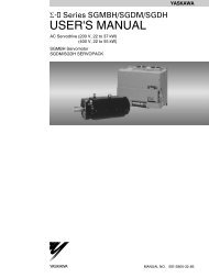
<strong>MP2600iec</strong><br />
<strong>Hardware</strong> <strong>Manual</strong>
Table of Contents<br />
Table of Contents<br />
1 Introduction<br />
1.1 <strong>MP2600iec</strong> Features - - - - - - - - - - - - - - - - - - - - - - - - 3<br />
1.2 <strong>MP2600iec</strong> Appearance- - - - - - - - - - - - - - - - - - - - - - 4<br />
1.3 Model Number Reference - - - - - - - - - - - - - - - - - - - - 5<br />
2 Specifications<br />
2.1 General Specifications - - - - - - - - - - - - - - - - - - - - - - - 7<br />
2.2 <strong>MP2600iec</strong> <strong>Hardware</strong> Specifications - - - - - - - - - - - - - 8<br />
3 Mechanical Installation<br />
3.1 Mounting Information- - - - - - - - - - - - - - - - - - - - - - - - 9<br />
3.2 Installation Standards - - - - - - - - - - - - - - - - - - - - - - 10<br />
3.3 Dimensions- - - - - - - - - - - - - - - - - - - - - - - - - - - - - - 11<br />
4 Inputs/Outputs<br />
4.1 CN13 Connection Diagram - - - - - - - - - - - - - - - - - - 13<br />
4.2 CN13 Connection Description - - - - - - - - - - - - - - - - 14<br />
4.3 External Encoder Interface - - - - - - - - - - - - - - - - - - 15<br />
4.4 Controller Digital I/O - - - - - - - - - - - - - - - - - - - - - - - 16<br />
4.5 Sigma-5 I/O - - - - - - - - - - - - - - - - - - - - - - - - - - - - - 18<br />
4.6 Analog I/O - - - - - - - - - - - - - - - - - - - - - - - - - - - - - - 19<br />
5 DIP Switches<br />
5.1 Switch Settings - - - - - - - - - - - - - - - - - - - - - - - - - - - 21<br />
6 LED Outputs - - - - - - - - - - - - - - - - - - - - - - - - - - - - - - - 23<br />
7 Battery<br />
7.1 Battery Installation- - - - - - - - - - - - - - - - - - - - - - - - - 25<br />
1
Table of Contents<br />
8 Ethernet<br />
8.1 Connectivity Information- - - - - - - - - - - - - - - - - - - - - 27<br />
8.2 Ethernet Connector Details- - - - - - - - - - - - - - - - - - - 27<br />
8.3 Ethernet Cable - - - - - - - - - - - - - - - - - - - - - - - - - - - 28<br />
8.4 Ethernet Connection Examples- - - - - - - - - - - - - - - - 28<br />
9 Cable Diagrams<br />
9.1 CBK-U-MP2B-xx (Terminal Block-Controller) - - - - - - 31<br />
9.2 CFC-U-MP2B-xx (Flying Lead-Controller) - - - - - - - - 32<br />
9.3 SBK-U-VBA-xx (Terminal Block-Servo Amp) - - - - - - 33<br />
9.4 JZSP-CSI02-x-E (Flying Lead-Servo Amp) - - - - - - - 34<br />
10 Cable Shielding, Segregation & Noise Immunity - 35<br />
11 Firmware Upgrade Procedure - - - - - - - - - - - - - - - - - 37<br />
2
1.1 <strong>MP2600iec</strong> Features<br />
1 Introduction<br />
1.1 <strong>MP2600iec</strong> Features<br />
<strong>MP2600iec</strong> is a single-axis machine controller option card that is<br />
attached to a Sigma-5 servo amplifier. The servo amplifier and<br />
controller are factory assembled, providing a compact, all-in-one<br />
servo/controller package with the following features:<br />
• PLCopen for Motion Control, including indexing, camming, gearing, and<br />
servo parameter maintenance capability.<br />
• Sigma-5 self-tuning, anti-vibration, and other high performance,<br />
easy-to-implement servo control features<br />
• Ethernet (100Mbps) Auto crossover switching<br />
• EtherNet/IP<br />
• Modbus TCP<br />
• Allows high-speed communications with MotionWorks IEC<br />
• Enables communication with the application program by using a<br />
touch panel<br />
• Enables communication with the application program from another<br />
controller<br />
• Combined Amplifier/Controller I/O features<br />
• 15 digital inputs<br />
• 11 digital outputs<br />
• 1 analog input<br />
• 1 analog output<br />
• 1 external encoder (quadrature, pulse + direction, up/down)<br />
• 1 external encoder latch<br />
3
1.2 <strong>MP2600iec</strong> Appearance<br />
1.2 <strong>MP2600iec</strong> Appearance<br />
The following figure shows the external appearance of the <strong>MP2600iec</strong><br />
controller (Note: The servo amplifier is not shown).<br />
LED (10 points)<br />
Ethernet Port A<br />
Ethernet Port B<br />
DIP Switch (6 points)<br />
CN13 Port<br />
Analog I/O, Digital I/O<br />
External Encoder (incremental)<br />
3.6V Lithium Battery<br />
(preserves retained variables,<br />
absolute encoder offset,<br />
and real-time clock data)<br />
4
1.3 Model Number Reference<br />
1.3.1 Model Number Designation<br />
1.3 Model Number Reference<br />
1.3.1 Model Number Designation<br />
SGDV<br />
R70 A E 1 A 000 00 0 300<br />
Current<br />
Voltage<br />
100V<br />
200V<br />
400V<br />
Series SGDV SERVOPACK<br />
Code<br />
Applicable Servomotor<br />
Max. Capacity kW<br />
R70 0.05<br />
R90 0.1<br />
2R1 0.2<br />
2R8 0.4<br />
R70* 0.05<br />
R90* 0.1<br />
1R6* 0.2<br />
2R8* 0.4<br />
3R8 0.5<br />
5R5* 0.75<br />
7R6 1.0<br />
120 ♣ 1.5<br />
180 2.0<br />
200 3.0<br />
330 5.0<br />
470 6.0<br />
550 7.5<br />
590 11<br />
780 15<br />
1R9 0.5<br />
3R5 1.0<br />
5R4 1.5<br />
8R4 2.0<br />
120 3.0<br />
170 5.0<br />
210 6.0<br />
260 7.5<br />
280 11<br />
370 15<br />
* These amplifiers can be powered with single or three-phase.<br />
♣ SGDV-120A¡¡A008000¡¡¡, a special version of the 1.5kW<br />
amplifier can be used for single-phase operation.<br />
Option Module<br />
Code Specifications<br />
<strong>MP2600iec</strong> 1.5 Axis<br />
300<br />
Machine Controller<br />
Module<br />
Options (parameter)<br />
Code Specifications<br />
0 standard<br />
Options (software)<br />
Code Specifications<br />
00 standard<br />
Options (hardware)<br />
Code Specifications<br />
000 Base-mounted<br />
(standard)<br />
Design Revision Order<br />
A, B…<br />
Motor Type<br />
Code Specifications<br />
1 Rotary Servomotors<br />
5** Linear Servomotors<br />
** Under Development<br />
Interface Options<br />
Code<br />
E<br />
Voltage<br />
Code<br />
F<br />
A<br />
D<br />
Specifications<br />
Communication Reference<br />
Specifications<br />
100 VAC<br />
200 VAC<br />
400 VAC<br />
5
1.3 Model Number Reference<br />
1.3.2 Accessory Model Numbers<br />
1.3.2 Accessory Model Numbers<br />
System Components<br />
Type Model Part Number Note<br />
Battery JZSP-BA01 Replacement<br />
Battery Holder Kit SGDV-OZC02A Replacement (does not include battery)<br />
Accessories/Cables<br />
CN13 (<strong>MP2600iec</strong>)<br />
Terminal Block<br />
Conversion Kit<br />
CN13 (<strong>MP2600iec</strong>)<br />
(Flying Leads)<br />
CN1 (Servo Amp)<br />
Terminal Block<br />
Conversion Kit<br />
CBK-U-MP2Bxx<br />
CFC-U-MP2Bxx<br />
SBK-U-MP2Bxx<br />
xx denotes cable length (m)<br />
A5 = 0.5<br />
01 = 1<br />
03 = 3<br />
CN1 (Servo Amp) Cable<br />
(Flying Leads)<br />
JZSP-CSI02-x-E<br />
x denotes cable length (m)<br />
A = 1 B = 2 C = 3<br />
Communication<br />
Ethernet Cable<br />
N/A<br />
Use commonly available shielded Ethernet<br />
cable<br />
Software<br />
MotionWorks IEC<br />
Express<br />
MotionWorks IEC Pro<br />
OPC Server<br />
PDE-U-IECSx<br />
PDE-U-IECPx<br />
PDE-U-OPCPx<br />
x denotes number of software licenses<br />
A = 1 B = 5 C = 10<br />
x denotes number of software licenses<br />
A = 1 B = 5 C = 10 D = 20<br />
6
2.1 General Specifications<br />
2 Specifications<br />
2.1 General Specifications<br />
Environmental<br />
Conditions<br />
Item<br />
Ambient Operating<br />
Temperature<br />
Ambient Storage<br />
Temperature<br />
Ambient Operating<br />
Humidity<br />
Ambient Storage<br />
Humidity<br />
Protection Class/<br />
Pollution Degree<br />
0 to 55°C<br />
-20°C to +85°C<br />
Specifications<br />
90% RH or less (with no condensation)<br />
90% RH or less (with no condensation)<br />
Protection class: IP10, Pollution degree: 2<br />
An environment that satisfies the following conditions.<br />
• Free of corrosive or explosive gases<br />
• Free of exposure to water, oil or chemicals<br />
• Free of dust, salts or iron dust<br />
Mechanical <br />
Operating <br />
Conditions<br />
Operating Altitude<br />
Vibration<br />
Resistance<br />
1,000 m above sea level or lower<br />
4.9 m/s 2<br />
Shock Resistance 19.6 m/s 2<br />
Others<br />
Free of static electricity, strong electromagnetic fields,<br />
magnetic fields or exposure to radioactivity<br />
7
2.2 <strong>MP2600iec</strong> <strong>Hardware</strong> Specifications<br />
2.2 <strong>MP2600iec</strong> <strong>Hardware</strong> Specifications<br />
Item<br />
Specification<br />
CPU 200 MHz, 32 bit, ARM 9<br />
Memory<br />
Operator interface<br />
User<br />
I/O<br />
Controller<br />
Side<br />
(CN13)<br />
Servo-<br />
Side<br />
(CN1)<br />
Network capability<br />
SDRAM<br />
SRAM<br />
Flash<br />
LED<br />
User Configuration<br />
Network<br />
Digital input<br />
Digital output<br />
Analog input<br />
Analog output<br />
Pulse Counter<br />
Sequence<br />
Input<br />
Sequence<br />
Output<br />
Programming standards<br />
Diagnostic and configuration interface<br />
Motion control performance<br />
Servo-Side Safety Functions<br />
Allocated*<br />
Fixed<br />
Allocated*<br />
Input<br />
Output<br />
32 MB<br />
512 kB with battery backup<br />
4 MB flash. Code and parameter storage.<br />
10 LEDs (red and green - operating mode,<br />
communication and error status)<br />
6x DIP switch (operating mode and communication<br />
configuration)<br />
2x 100baseTX Ethernet<br />
8 programmable inputs<br />
8 programmable outputs<br />
1 ch., +/- 10V, 16 bit<br />
1 ch., +/- 10V, 16 bit<br />
RS-422-compatible pulse counter input (quadrature,<br />
pulse and direction, and up/down counter modes) with<br />
5, 12, or 24V position latch input<br />
Number of Inputs: 7<br />
Functions: The signal allocation and positive/negative<br />
logic can be modified. Forward run prohibited (P-OT),<br />
reverse run prohibited (N-OT), forward torque limit (/P-<br />
CL), reverse torque limit (/N-CL), general-purpose<br />
input signal (/SI0 to /SI6)<br />
Servo Alarm (ALM)<br />
Number of Outputs: 3<br />
Functions: The signal allocation and positive/negative<br />
logic can be modified. Positioning completion (/COIN),<br />
speed coincidence detection(/V-CMP), servomotor<br />
rotation detection (/TGON), servo ready (/S-RDY),<br />
torque limit detection (/CLT), speed limit detection<br />
(VLT), brake (/BK), warning (/WARN), near (/NEAR)<br />
OPC (Client and Server required)<br />
EtherNet/IP<br />
Modbus/TCP<br />
IEC61131-3/PLCopen<br />
Web interface<br />
1 controlled axis and one external position input at a<br />
trajectory update rate of 1 kHz<br />
/HWBB1, /HWBB2: Baseblock signal for power<br />
module<br />
EDM1: Status monitor (fixed output) of built-in safety<br />
circuit<br />
* Allocated I/O can also be used as programmable I/O if the output functions are disabled.<br />
8
3.1 Mounting Information<br />
3 Mechanical Installation<br />
3.1 Mounting Information<br />
The <strong>MP2600iec</strong> controller is pre-assembled to the Sigma-5 servo<br />
amplifier by the factory.<br />
9
3.2 Installation Standards<br />
3.2 Installation Standards<br />
The servo amplifier must be installed in a fully enclosed metal control panel. Observe the standards<br />
for mounting servo amplifiers in control panels, including those for the mounting servo amplifiers side<br />
by side in one control panel as shown in the following illustration.<br />
• Servo Amplifier Mounting Orientation<br />
Mount the servo amplifier vertically to the wall, with the front panel (the side with the panel operator<br />
display) facing out.<br />
• Cooling<br />
Refer to the following diagram and leave sufficient space for cooling by fans and natural convection.<br />
• Mounting Servo Amplifiers Side by Side in a Control Panel<br />
Fan<br />
Fan<br />
40 mm or more<br />
40 mm or more<br />
30 mm or more<br />
Width varies with<br />
servo amplifier model<br />
Leave sufficient space on each side and at the top and the bottom of each servo amplifier. The<br />
width on each side varies in accordance with the models of the servo amplifiers used.<br />
Side<br />
Servo Amplifier Model SGDV-<br />
Left<br />
Right<br />
R70F, R90F, 2R1F, R70A, R90A, 1R6A, 2R8A<br />
1 mm or more<br />
2R8F, 3R8A, 5R5A, 7R6A 1 mm or more 10 mm or more<br />
120A, 180A, 200A, 330A, 470A, 550A, 590A, 780A,<br />
1R9D, 3R5D, 5R4D, 8R4D, 120D, 170D, 210D, 260D,<br />
10 mm or more<br />
280D, 370D<br />
Top and bottom<br />
40 mm or more<br />
Also install cooling fans above the servo amplifiers to disperse local pockets of warmer air around<br />
the servo amplifiers.<br />
• Inside the Control Panel<br />
The conditions inside the control panel should be the same as the environmental conditions of<br />
the servo amplifier. Refer to the environmental . conditions in 2.1 General Specifications<br />
• During Operation<br />
Do not touch the connectors or IO cables during operation if the panel door is open.<br />
.<br />
10
3.3 Dimensions<br />
3.3.1 <strong>MP2600iec</strong> Controller<br />
3.3 Dimensions<br />
3.3.1 <strong>MP2600iec</strong> Controller<br />
20<br />
(22)<br />
160<br />
20<br />
(20)<br />
97<br />
Dimensions in mm.<br />
11
3.3 Dimensions<br />
3.3.1 <strong>MP2600iec</strong> Controller<br />
This page left intentionally blank<br />
12
4.1 CN13 Connection Diagram<br />
4 Inputs/Outputs<br />
4.1 CN13 Connection Diagram<br />
CN13<br />
+15<br />
V<br />
Analog<br />
Output<br />
-<br />
+<br />
-15V<br />
1 AO<br />
26 AO_GND<br />
External Device<br />
L<br />
-10 +10V<br />
+15<br />
V<br />
FG<br />
External Device<br />
Analog<br />
Input<br />
-<br />
+<br />
-15V<br />
2 AI<br />
27 AI_GND<br />
V<br />
-10 +10V<br />
FG<br />
Encoder<br />
Interface<br />
4<br />
5<br />
PA+<br />
PA-<br />
29 PB+<br />
30 PB-<br />
6 GND<br />
31 GND<br />
Pulse<br />
Generator<br />
Z-phase<br />
Latch Input<br />
10 PILC(24V)<br />
34 PILC(12V)<br />
9 PILC(5V)<br />
35 PIL<br />
FG<br />
Connect to pin 10, 34, or 9 based on signal level<br />
Latch Input<br />
+5V<br />
Digital<br />
Input<br />
13 DICOM<br />
38 DICOM<br />
14 DI_00<br />
39 DI_01<br />
15 DI_02<br />
40 DI_03<br />
16 DI_04<br />
41 DI_05<br />
17 DI_06<br />
42 DI_07<br />
External Input<br />
Signal<br />
21<br />
DO_00+<br />
L<br />
+24VDC<br />
11<br />
46<br />
DO_00-<br />
DO_01+<br />
L<br />
0V<br />
+24VDC<br />
36<br />
22<br />
DO_01-<br />
DO_02+<br />
L<br />
0V<br />
+24VDC<br />
L<br />
Load<br />
Digital<br />
Output<br />
12<br />
47<br />
DO_02-<br />
DO_03+<br />
L<br />
0V<br />
+24VDC<br />
External Fuse<br />
(installed by<br />
customer)<br />
37<br />
23<br />
DO_03-<br />
DO_04+<br />
L<br />
0V<br />
+24VDC<br />
Polyswitch Device:<br />
A self-resetting<br />
fuse if excessive<br />
current is drawn<br />
from the output<br />
18<br />
48<br />
43<br />
24<br />
DO_04-<br />
DO_05+<br />
DO_05-<br />
DO_06+<br />
L<br />
L<br />
0V<br />
+24VDC<br />
0V<br />
+24VDC<br />
19 DO_06-<br />
49 * DO_07+<br />
L<br />
0V<br />
+24VDC<br />
44<br />
* DO_07-<br />
0V<br />
FG Connector Shell)<br />
7 + Battery<br />
32 - Battery<br />
NOTE: For a more detailed circuit drawing, see section 5.4.2.<br />
* DO_07 can also be used as a high speed output when<br />
configured via parameter 1050<br />
13
4.2 CN13 Connection Description<br />
4.2 CN13 Connection Description<br />
Numerical<br />
CN 13 Pin Code Description<br />
1 AO Analog Output<br />
2 AI Analog Input<br />
3 n/c no connection<br />
4 PA+ Encoder A phase +<br />
5 PA- Encoder A phase -<br />
6 GND Encoder ground<br />
7 BAT + SRAM Positive Battery input<br />
8 n/c no connection<br />
9 PILC PC+ / External Encoder Latch +5V<br />
10 PILC PC+ / External Encoder Latch +24V<br />
11 DO_00- Digital Output 0 -<br />
12 DO_02- Digital Output 2 -<br />
13 DICOM Digital Input Common<br />
14 DI_00 Digital Input 0<br />
15 DI_02 Digital Input 2<br />
16 DI_04 Digital Input 4<br />
17 DI_06 Digital Input 6<br />
18 DO_04- Digital Output 4 -<br />
19 DO_06- Digital Output 6 -<br />
20 n/c no connection<br />
21 DO_00+ Digital Output 0 +<br />
22 DO_02+ Digital Output 2 +<br />
23 DO_04+ Digital Output 4 +<br />
24 DO_06+ Digital Output 6 +<br />
25 n/c no connection<br />
26 AO_GND Analog Output Ground<br />
27 AI_GND Analog Input Ground<br />
28 n/c no connection<br />
29 PB+ Encoder B phase +<br />
30 PB- Encoder B phase -<br />
31 GND Encoder ground<br />
32 BAT - SRAM Negative Battery input<br />
33 n/c no connection<br />
34 PILC PC+ / External Encoder Latch +12V<br />
35 PIL PC- / External Encoder Latch<br />
36 DO_01- Digital Output 1 -<br />
37 DO_03- Digital Output 3 -<br />
38 DICOM Digital Input Common<br />
39 DI_01 Digital Input 1<br />
40 DI_03 Digital Input 3<br />
41 DI_05 Digital Input 5<br />
42 DI_07 Digital Input 7<br />
43 DO_05- Digital Output 5 -<br />
44 DO_07- Digital Output 7 -<br />
45 n/c no connection<br />
46 DO_01+ Digital Output 1 +<br />
47 DO_03+ Digital Output 3 +<br />
48 DO_05+ Digital Output 5 +<br />
49 DO_07+ Digital Output 7 +<br />
50 n/c no connection<br />
Alphabetical<br />
Description Code CN 13 Pin<br />
Analog Input AI 2<br />
Analog Input Ground AI_GND 27<br />
Analog Output AO 1<br />
Analog Output Ground AO_GND 26<br />
Digital Input 0 DI_00 14<br />
Digital Input 1 DI_01 39<br />
Digital Input 2 DI_02 15<br />
Digital Input 3 DI_03 40<br />
Digital Input 4 DI_04 16<br />
Digital Input 5 DI_05 41<br />
Digital Input 6 DI_06 17<br />
Digital Input 7 DI_07 42<br />
Digital Input Common DICOM 13<br />
Digital Input Common DICOM 38<br />
Digital Output 0 - DO_00- 11<br />
Digital Output 0 + DO_00+ 21<br />
Digital Output 1 - DO_01- 36<br />
Digital Output 1 + DO_01+ 46<br />
Digital Output 2 - DO_02- 12<br />
Digital Output 2 + DO_02+ 22<br />
Digital Output 3 - DO_03- 37<br />
Digital Output 3 + DO_03+ 47<br />
Digital Output 4 - DO_04- 18<br />
Digital Output 4 + DO_04+ 23<br />
Digital Output 5 - DO_05- 43<br />
Digital Output 5 + DO_05+ 48<br />
Digital Output 6 - DO_06- 19<br />
Digital Output 6 + DO_06+ 24<br />
Digital Output 7 - DO_07- 44<br />
Digital Output 7 + DO_07+ 49<br />
Encoder A phase - PA- 5<br />
Encoder A phase + PA+ 4<br />
Encoder B phase - PB- 30<br />
Encoder B phase + PB+ 29<br />
Encoder ground GND 6<br />
Encoder ground GND 31<br />
no connection n/c 3<br />
no connection n/c 8<br />
no connection n/c 20<br />
no connection n/c 25<br />
no connection n/c 28<br />
no connection n/c 33<br />
no connection n/c 45<br />
no connection n/c 50<br />
PC- / External Encoder Latch PIL 35<br />
PC+ / External Encoder Latch+12V PILC 34<br />
PC+ / External Encoder Latch+24V PILC 10<br />
PC+ / External Encoder Latch +5V PILC 9<br />
SRAM Negative Battery input BAT - 32<br />
SRAM Positive Battery input BAT + 7<br />
Note: DO_07 can also be used as a high speed output when configured via parameter 1050. See the PLCopen Plus<br />
Axis Parameters for more details.<br />
14
4.3 External Encoder Interface<br />
4.3 External Encoder Interface<br />
Item<br />
Number of<br />
channels<br />
Input circuit<br />
Counter modes<br />
Latch input<br />
Specification<br />
One channel (Phase A, Phase B, Index pulse)<br />
Phase A & B: 5V differential input (RS-422 compatible), non-insulated.<br />
Maximum frequency 4MHz.<br />
Index pulse: 5V/12V/24V photo coupler input. Maximum frequency<br />
500kHz (pre-quadrature. This signal is used for external encoder latch.<br />
Quadrature, pulse and direction, up/down<br />
Latch on index pulse or DI_01 digital input.<br />
<strong>Hardware</strong> latency: 5s or less (index pulse)<br />
Two RS-422 compatible inputs are provided for encoder phases A and<br />
B. One position latch input which supports a 5V, 12V, or 24V digital input <br />
signal is provided.<br />
CN13 Connector<br />
Pulse generator<br />
4<br />
PA+<br />
Phase A<br />
+5V<br />
R<br />
5<br />
PB-<br />
PA-<br />
0V<br />
29<br />
PB+<br />
Phase B<br />
+5V<br />
R<br />
30<br />
6<br />
GND<br />
0V<br />
+5V<br />
31<br />
GND<br />
R<br />
35<br />
PIL<br />
R<br />
9<br />
PILC(5V)<br />
R<br />
34<br />
PILC(12V)<br />
R<br />
10<br />
PILC(24V)<br />
Encoder Input Circuit<br />
15
4.4 Controller Digital I/O<br />
4.4.1 Inputs<br />
4.4 Controller Digital I/O<br />
4.4.1 Inputs<br />
• 8 general purpose<br />
• Optically isolated<br />
• 24 V @ 5 mA<br />
• Entire bank is configurable as either current sinking or sourcing via<br />
connection of common<br />
Digital Input Circuit<br />
To configure all controller inputs as sinking, wire +24VDC to pins 13<br />
and 38. To configure all controller inputs as sourcing, wire 0VDC to<br />
pins 13 and 38. Refer to diagram in Section 5.1.<br />
16
4.4.2 Outputs<br />
4.4 Controller Digital I/O<br />
4.4.2 Outputs<br />
• 8 general purpose<br />
• Optically isolated<br />
• 24 V @ 50 mA<br />
• Current source or sink (connection to both emitter and collector are<br />
provided)<br />
• High speed digital output feature can set DO_07 within 13s of passing a<br />
specified encoder position. See Axis Parameters in the PLCopen Plus<br />
Function Block <strong>Manual</strong> to configure.<br />
Digital Output Circuit<br />
Connection Examples of Output Circuits<br />
• Relay Circuit Example<br />
SERVOPACK<br />
5 to 24 VDC<br />
Relay<br />
0V<br />
• Line Receiver Circuit Example<br />
SERVOPACK<br />
5 to 12 VDC<br />
17
4.5 Sigma-5 I/O<br />
4.4.2 Outputs<br />
4.5 Sigma-5 I/O<br />
The Sigma-5 includes seven digital inputs and three digital outputs<br />
that can be monitored and controlled by the <strong>MP2600iec</strong>.<br />
Sigma-5 SGDV Servo Amp<br />
Photocoupler output<br />
Max. operating voltage: 30 VDC<br />
Max. operating current: 50 mA DC<br />
CN1<br />
Control power supply<br />
for sequence signal *3<br />
Forward run prohibited<br />
(Prohibited when OFF)<br />
Reverse run prohibited<br />
(Prohibited when OFF)<br />
Command option<br />
module input 3 *4<br />
+24V 6 3.3kΩ<br />
/SI1 7<br />
/SI2 8<br />
/SI3 9<br />
3 ALM+<br />
4 ALM-<br />
Servo alarm output<br />
(OFF for an alarm)<br />
1 SO1+ / BK+<br />
Brake output<br />
2 SO1- / BK- (Brake released when ON)<br />
23 /SO2+<br />
24 /SO2-<br />
General-purpose outputs<br />
25 /SO3+<br />
Command option<br />
module input 4 *4<br />
Command option<br />
module input 5 *4<br />
Command option<br />
module input 6 *4<br />
General-purpose input 0<br />
Backup battery *2<br />
(2.8 to 4.5 V)<br />
/SI4 10<br />
/SI5 11<br />
/SI6 12<br />
/SI0 13<br />
BAT+<br />
14<br />
BAT- 15<br />
26 /SO3-<br />
17 PAO<br />
18 /PAO<br />
19 PBO<br />
20 /PBO<br />
21 PCO<br />
22 /PCO<br />
16 SG<br />
Encoder output<br />
pulses phase A<br />
Encoder <br />
output<br />
pulses phase B<br />
Encoder output<br />
pulses phase C<br />
Signal ground<br />
Applicable line<br />
receiver<br />
SN75ALS175<br />
manufactured by<br />
Texas Instruments<br />
or an MC3486<br />
equivalent<br />
* 1<br />
18
4.6 Analog I/O<br />
4.6.1 Analog Input<br />
4.6 Analog I/O<br />
4.6.1 Analog Input<br />
Item<br />
Analog input range -10V ~ +10V<br />
Number of input channels 1<br />
Electrical isolation<br />
Absolute maximum input<br />
Input Impedance<br />
Resolution<br />
Accuracy<br />
Input filter<br />
Conversion time<br />
None<br />
± 15V<br />
20k<br />
16 bit<br />
25°C ±0.1% (± 10mV)<br />
0 ~ 55°C ±0.3% (± 30mV)<br />
Time constant<br />
Delay time<br />
Specification<br />
=130s (63.2% rise time)<br />
1ms maximum (for full-range -10V to<br />
+10V slew)<br />
50s<br />
CN13 Connector<br />
To A/D<br />
Conversion<br />
20K<br />
10K<br />
2<br />
AI<br />
10K<br />
27<br />
AI_GND<br />
GND<br />
Analog Input Circuit<br />
19
4.6 Analog I/O<br />
4.6.2 Analog Output<br />
4.6.2 Analog Output<br />
Item<br />
Specification<br />
Analog output range -10V ~ +10V<br />
Number of output channels 1<br />
Electrical isolation<br />
None<br />
Maximum load current<br />
± 5mA<br />
Resolution<br />
16 bit<br />
Accuracy<br />
25°C ±0.45% (± 45mV)<br />
0 ~ 55°C ±0.60% (± 60mV)<br />
Output delay time<br />
less than 1ms<br />
CN13 Connector<br />
+15<br />
V<br />
-<br />
+<br />
-15V<br />
1<br />
26<br />
AO<br />
AO_GND<br />
Analog Output Circuit<br />
20
5.1 Switch Settings<br />
5 DIP Switches<br />
5.1 Switch Settings<br />
STOP<br />
SUP<br />
INT<br />
CNFG<br />
EINIT<br />
DHCP<br />
NO<br />
S11<br />
Switch Name Setting Operating Mode<br />
Setting for<br />
Normal<br />
Operation<br />
Details<br />
1 STOP<br />
2 SUP<br />
3 INIT<br />
4 CNFG<br />
5 E-INIT<br />
6 DHCP<br />
ON<br />
OFF<br />
ON<br />
OFF<br />
ON<br />
OFF<br />
ON<br />
OFF<br />
ON<br />
OFF<br />
ON<br />
OFF<br />
User program execution<br />
inhibited OFF Inhibits user program execution<br />
Normal operation<br />
Firmware programming<br />
mode<br />
Normal operation<br />
SRAM/clock initialization<br />
and configuration bypass<br />
mode<br />
Normal operation<br />
Normal operation<br />
Do not set (reserved for<br />
future use)<br />
Force Ethernet address<br />
setting for Port A to<br />
192.168.1.1 and Port B<br />
to 192.168.2.1<br />
Normal Operation<br />
DHCP-configured IP<br />
settings<br />
<strong>Manual</strong>ly-configured IP<br />
settings<br />
OFF<br />
OFF<br />
ON<br />
OFF<br />
OFF<br />
Enables controller firmware programming.<br />
(See Section 11)<br />
Set to ON to bypass the stored configuration<br />
(e.g. in case of a configuration problem that<br />
prevents controller startup) or to initialize the<br />
SRAM contents and clock settings after<br />
backup power has been lost (See Section<br />
7.1).<br />
Always set to ON<br />
Enables use of the default Ethernet<br />
addresses<br />
Enables use of DHCP for IP setting<br />
configuration<br />
21
5.1 Switch Settings<br />
This page left intentionally blank<br />
22
6 L E D O u t p u t s<br />
6 LED Outputs<br />
The following table shows the indicators that show the operating<br />
status of the controller and error information.<br />
RDY<br />
ALM<br />
BAT<br />
LINK<br />
A<br />
LINK<br />
B<br />
RUN<br />
ERR<br />
CTRL<br />
TRX<br />
A<br />
TRX<br />
B<br />
Indicator Color Status<br />
RDY Green Lit during normal operation.<br />
RUN Green Lit during execution of user program.<br />
ALM Red Lit when alarm occurs.<br />
ERR Red Lit when malfunction occurs.<br />
CTRL Green<br />
Lit when option card is communicating to the<br />
servo amplifier.<br />
BAT Red Lit during battery alarm.<br />
TRX A Green Lit during Ethernet CN11A activity.<br />
LINK A Green Lit during Ethernet CN11A link up.<br />
TRX B Green Lit during Ethernet CN11B activity.<br />
LINK B Green Lit during Ethernet CN11B link up.<br />
23
6 LED Outputs<br />
This page left intentionally blank<br />
24
7.1 Battery Installation<br />
7 Battery<br />
7.1 Battery Installation<br />
A 3.6V lithium battery must be used to retain SRAM data in the<br />
controller when the power is off. SRAM will last for one hour without<br />
the battery connected. The battery power can be applied through the<br />
battery connector (CN14), or through the I/O connector (CN13 pins<br />
7[+] & 32[-]). The battery is necessary for preserving retained<br />
variables, absolute encoder offset, and real-time clock data.<br />
Option Case<br />
(snaps off unit)<br />
Metal plate for<br />
connection<br />
1<br />
Screw<br />
-<br />
+<br />
3<br />
Battery Holder<br />
2<br />
Battery<br />
To initialize the non-volatile memory and clock settings after a battery<br />
is attached for the first time (or any time backup power has been lost),<br />
use the following procedure.<br />
1. Power off the <strong>MP2600iec</strong>.<br />
2. Set the “INIT” switch (S11) to ON.<br />
3. Power on the <strong>MP2600iec</strong> and wait for the “RDY” LED to illuminate.<br />
4. Power off the <strong>MP2600iec</strong>.<br />
5. Set the “INIT” switch (S11) to OFF.<br />
25
7.1 Battery Installation<br />
Battery Holder Installation Instructions:<br />
1. Remove the plastic case from the<br />
controller by pressing the tabs at the<br />
top and bottom.<br />
2. Insert the tab of the metal plate<br />
into the last vent slot on the bottom<br />
front of the case as shown.<br />
3. Line up the hole in battery holder<br />
with the hole in the metal plate and<br />
secure the battery holder with the<br />
screw provided.<br />
4. Attach the extension cable to the<br />
battery and place the battery into the<br />
battery holder with the cable facing<br />
forward.<br />
5. Attach the plastic case to the<br />
controller.<br />
6. Plug the battery extension cable<br />
into the battery connector (CN14).<br />
26
8.1 Connectivity Information<br />
8 Ethernet<br />
8.1 Connectivity Information<br />
The <strong>MP2600iec</strong> supports 100MB speeds exclusively. Two separate<br />
networks are possible using both CN11A and CN11B. A default<br />
gateway can be specified only for the network attached to CN11A.<br />
8.2 Ethernet Connector Details<br />
Ethernet Connector Specification and Pin Array<br />
The following table provides the Ethernet connector specifications.<br />
Connector Number<br />
Connector Model<br />
Name of Pins Module Side Cable Side Manufacturer<br />
Ethernet 8 RJ-45 CAT5 Socket RJ-45 CAT5 Plug Pulse Engineering<br />
The following table provides Ethernet connector pin array / indicator<br />
light details.<br />
Ethernet<br />
Pin Number Signal Name Description<br />
1 TXD+ Transmitted data + side<br />
2 TXD- Transmitted data – side<br />
3 RXD+ Received data + side<br />
4 – –<br />
5 – –<br />
6 RXD- Received data – side<br />
7 – –<br />
8 – –<br />
27
8.3 Ethernet Cable<br />
8.3 Ethernet Cable<br />
For the Ethernet cable, use a twisted pair cable with RJ-45<br />
connector. Yaskawa strongly recommends the use of shielded<br />
ethernet cables. Ethernet ports are capable of auto-crossover, so<br />
crossover cables are not necessary.<br />
8.4 Ethernet Connection Examples<br />
Connection Example 1 (When using a repeater HUB)<br />
Sigma-5 with<br />
<strong>MP2600iec</strong><br />
Station*<br />
Station*<br />
100Base-TX<br />
Up to 100m<br />
Up to 100m<br />
Up to 100m<br />
100Base-TX<br />
Ethernet Switch<br />
Up to 100m<br />
100Base-TX<br />
Ethernet Switch<br />
Up to 100m<br />
Station*<br />
Up to 100m<br />
Station*<br />
* Note: The <strong>MP2600iec</strong> can only be plugged into<br />
a 100Base-TX Ethernet port.<br />
Specification<br />
Item<br />
Cable Length between Node-HUB<br />
Cable Length between HUBs<br />
Number of HUBs between Nodes<br />
When Connecting to a<br />
Ethernet Switch<br />
100 m or less<br />
100 m or less<br />
Unlimited<br />
28
8.4 Ethernet Connection Examples<br />
Connection Example 2<br />
Sigma-5 with <strong>MP2600iec</strong><br />
100 Base-TX (up to 100m)<br />
Note: The <strong>MP2600iec</strong> can only be plugged<br />
into a 100Base-TX Ethernet port.<br />
• Caution<br />
High frequency wave noise from other devices in the installation environment<br />
may cause errors in communications. When designing a system, use protective<br />
measures to avoid the influence of high frequency wave noise as follows:<br />
1. Wiring<br />
Wire Ethernet cables so that they are well-separated from other cable<br />
systems such as the main circuit or power lines.<br />
2. Communication system (Ethernet)<br />
• Communicate data to a remote device.<br />
• Yaskawa strongly recommends shielded Ethernet cables.<br />
3. Attach a ferrite core.<br />
This will help reduce the occurrence of electrical interference.<br />
Recommended ferrite core:<br />
Model<br />
E04SR301334<br />
Manufacturer<br />
Seiwa Electric Mfg. Co., Ltd<br />
29
8.4 Ethernet Connection Examples<br />
Connection Example 3<br />
Sigma-5 with <strong>MP2600iec</strong><br />
Station*<br />
* Note: The <strong>MP2600iec</strong> can only be plugged<br />
into a 100Base-TX Ethernet port<br />
Core<br />
100Base-TX<br />
Core<br />
100Base-TX<br />
Ethernet Switch<br />
Servomotor<br />
MotionWorks IEC<br />
30
9.1 CBK-U-MP2B-xx<br />
9 Cable Diagrams<br />
9.1 CBK-U-MP2B-xx<br />
Terminal Block - Controller<br />
CBK-U-MP2B-XX Function Chart for <strong>MP2600iec</strong><br />
Pin Signal<br />
Pin Signal<br />
I/O<br />
Function<br />
No. Name<br />
No. Name<br />
I/O<br />
Function<br />
1 AO O Analog output 26 AO_GND O Analog output ground<br />
2 AI I Analog input 27 AI_GND I Analog input ground<br />
3 - - - 28 reserved -<br />
4 PA+ I Phase A pulse (+) 29 PB+ I Phase B pulse (+)<br />
5 PA- I Phase A pulse (-) 30 PB- I Phase B pulse (-)<br />
6 GND P Encoder input ground 31 GND P Encoder input ground<br />
7 BAT+ P Controller SRAM Battery (+) 32 BAT- P Controller SRAM Battery (-)<br />
8 - - - 33 - - -<br />
9 PILC5V I<br />
Phase-C latch pulse (-) for<br />
Phase-C latch pulse (-) for 12VDC<br />
34 PILC12V I<br />
5VDC input<br />
input<br />
10 PILC24V I<br />
Phase-C latch pulse (-) for<br />
24VDC input<br />
35 PIL I Phase-C latch pulse (+)<br />
11 DO_00- O Digital output 0 (-) 36 DO_01- O Digital output 1 (-)<br />
12 DO_02- O Digital output 2 (-) 37 DO_03- O Digital output 3 (-)<br />
13 DICOM I Digital input common 38 DICOM I Digital input common<br />
14 DI_00 I Digital input 0 39 DI_01 I<br />
Digital input 1<br />
(shared with pulse latch input)<br />
15 DI_02 I Digital input 2 40 DI_03 I Digital input 3<br />
16 DI_04 I Digital input 4 41 DI_05 I Digital input 5<br />
17 DI_06 I Digital input 6 42 DI_07 I Digital input 7<br />
18 DO_04- O Digital output 4 (-) 43 DO_05- O Digital output 5 (-)<br />
19 DO_06- O Digital output 6 (-) 44 DO_07- O Digital output 7 (-)<br />
20 - - - 45 - - -<br />
21 DO_00+ O Digital output 0 (+) 46 DO_01+ O Digital output 1 (+)<br />
22 DO_02+ O Digital output 2 (+) 47 DO_03+ O Digital output 3 (+)<br />
23 DO_04+ O Digital output 4 (+) 48 DO_05+ O Digital output 5 (+)<br />
24 DO_06+ O Digital output 6 (+) 49 DO_07+ O<br />
Digital output 7 (+) (shared with<br />
position agreement 'COIN' signal)<br />
25 - - - 50 - - -<br />
I = Input, O = Output, P = Power<br />
31
9.2 CFC-U-MP2B-xx<br />
9.2 CFC-U-MP2B-xx<br />
Flying Lead - Controller<br />
Dimensions in mm<br />
Model<br />
CFC-U-MP2B-A5<br />
CFC-U-MP2B-01<br />
CFC-U-MP2B-03<br />
X =Cable Length<br />
500 mm<br />
1000 mm<br />
3000 mm<br />
Pin<br />
No.<br />
Color<br />
(Solid/Band)<br />
Signal<br />
Name<br />
Pin<br />
No.<br />
Color<br />
(Solid/Band)<br />
Signal<br />
Name<br />
I/O Function<br />
I/O Function<br />
1 BLK/RED AO O Analog output 26 RED/BLK AO_GND O<br />
Analog output<br />
ground<br />
2 BLK/WHT AI I Analog input 27 WHT/BLK AI_GND I Analog input ground<br />
3 RED/GRN - - - 28 GRN/RED - - -<br />
4 BLK/BLU PA+ I Phase A pulse (+) 29 BLK/BRN PB+ I Phase B pulse (+)<br />
5 BLU/BLK PA- I Phase A pulse (-) 30 BRN/BLK PB- I Phase B pulse (-)<br />
6 RED/BLU GND P<br />
Encoder input<br />
Encoder input<br />
31 BLU/RED GND P<br />
ground<br />
ground<br />
7 RED/WHT BAT+ P<br />
Controller SRAM<br />
Controller SRAM<br />
32 WHT/RED BAT- P<br />
Battery (+)<br />
Battery (-)<br />
8 BLK/GRN - - - 33 GRN/BLK - - -<br />
9 BLK/YEL PILC5V I<br />
Phase-C latch pulse<br />
Phase-C latch pulse<br />
34 ORG/BLK PILC12V I<br />
(-) for 5VDC input<br />
(-) for 12VDC input<br />
10 BLK/ORG PILC24V I<br />
Phase-C latch pulse<br />
Phase-C latch pulse<br />
35 YEL/BLK PIL I<br />
(-) for 24VDC input<br />
(+)<br />
11 RED/YEL DO_00- O Digital output 0 (-) 36 WHT/ORG DO_01- O Digital output 1 (-)<br />
12 RED/BRN DO_02- O Digital output 2 (-) 37 BLU/YEL DO_03- O Digital output 3 (-)<br />
13 RED/ORG DICOM I Digital input common 38 ORG/RED DICOM I<br />
Digital input<br />
common<br />
14 GRN/WHT DI_00 I Digital input 0 39 WHT/GRN DI_01 I<br />
Digital input 1<br />
(shared with pulse<br />
latch input)<br />
15 GRN/BLU DI_02 I Digital input 2 40 BLU/GRN DI_03 I Digital input 3<br />
16 GRN/YEL DI_04 I Digital input 4 41 YEL/GRN DI_05 I Digital input 5<br />
17 GRN/BRN DI_06 I Digital input 6 42 BRN/GRN DI_07 I Digital input 7<br />
18 GRN/ORG DO_04- O Digital output 4 (-) 43 BLU/BRN DO_05- O Digital output 5 (-)<br />
19 WHT/BLU DO_06- O Digital output 6 (-) 44 BLU/ORG DO_07- O Digital output 7 (-)<br />
20 WHT/YEL - - - 45 YEL/WHT - - -<br />
21 YEL/RED DO_00+ O Digital output 0 (+) 46 ORG/WHT DO_01+ O Digital output 1 (+)<br />
22 BRN/RED DO_02+ O Digital output 2 (+) 47 YEL/BLU DO_03+ O Digital output 3 (+)<br />
23 ORG/GRN DO_04+ O Digital output 4 (+) 48 BRN/BLU DO_05+ O Digital output 5 (+)<br />
24 BLU/WHT DO_06+ O Digital output 6 (+) 49 ORG/BLU DO_07+ O<br />
Digital output 7 (+)<br />
(shared with position<br />
agreement 'COIN'<br />
signal)<br />
25 WHT/BRN - - - 50 BRN/WHT - - -<br />
32
9.3 SBK-U-VBA-xx<br />
9.3 SBK-U-VBA-xx<br />
Terminal Block - Servo Amplifier.<br />
SBK-U-VBA-xx Function Chart for SGDV Servo Amplifier<br />
Pin No.<br />
SGDV Mechatrolink-II type / SGDV Option type<br />
Signal<br />
Function<br />
1 /BK+ (/SO1+) Brake interlock output (+) (General purpose output 1 (+))<br />
2 /BK- (/SO1-) Brake interlock output (-) (General purpose output 1 (-))<br />
3 ALM+ Servo alarm output (+)<br />
4 ALM- Servo alarm output (-)<br />
5 -<br />
6 +24VIN Control power supply for sequence signal input<br />
7 P-OT (/SI1) Forward run prohibited input (General purpose input 1)<br />
8 N-OT (/SI2) Reverse run prohibited input (General purpose input 2)<br />
9 /DEC (/SI3) Zero-point return deceleration switch input (General purpose input 3)<br />
10 /EXT1 (/SI4) External latch signal 1 input (General purpose input 4)<br />
11 /EXT2 (/SI5) External latch signal 2 input (General purpose input 5)<br />
12 /EXT3 (/SI6) External latch signal 3 input (General purpose input 6)<br />
13 /SI0 General purpose input 0<br />
14 BAT (+) Battery (+) input<br />
15 BAT (-) Battery (-) input<br />
16 SG Signal ground<br />
17 PAO Phase-A pulse output (+)<br />
18 /PAO Phase-A pulse output (-)<br />
19 PBO Phase-B pulse output (+)<br />
20 /PBO Phase-B pulse output (-)<br />
21 PCO Phase-C pulse output (+)<br />
22 /PCO Phase-C pulse output (-)<br />
23 /SO2+ General purpose output 2 (+)<br />
24 /SO2- General purpose output 2 (-)<br />
25 /SO3+ General purpose output 3 (+)<br />
26 /SO3- General purpose output 3 (-)<br />
Note: General purpose input and output signals are shown with their default signals assigned - signal<br />
assignment may have been changed by parameter<br />
33
9.4 JZSP-CSI02-x-E<br />
9.4 JZSP-CSI02-x-E<br />
Flying Lead - Servo Amplifier<br />
SERVOPACK End<br />
Connector 10126-6000EL (by Sumitomo 3M Ltd.)<br />
Shell 10326-52A0-008<br />
Cable (Ivory)<br />
SSRFPVV-SB AWG#28 × 13P<br />
UL20276 VW-1SC<br />
3 Dia. Wire Markers<br />
37.2<br />
14 L<br />
100 +10 -0<br />
(6.3 Dia.)<br />
Dimensions in mm<br />
Model<br />
JZSP-CSI02-1-E<br />
JZSP-CSI02-2-E<br />
JZSP-CSI02-3-E<br />
Cable Length<br />
1000 mm<br />
2000 mm<br />
3000 mm<br />
34<br />
SERVOPACK End<br />
Pin No. Signal<br />
Wire Marking<br />
Color Color Dots<br />
1<br />
2<br />
3<br />
4<br />
5<br />
6<br />
7<br />
8<br />
9<br />
10<br />
11<br />
12<br />
13<br />
/BK+<br />
/BK−<br />
ALM+<br />
ALM−<br />
–<br />
+24VIN<br />
P-OT<br />
N-OT<br />
/DEC<br />
/EXT1<br />
/EXT2<br />
/EXT3<br />
/SI0<br />
Blue<br />
Blue<br />
Pink<br />
Pink<br />
Green<br />
Green<br />
Orange<br />
Orange<br />
Gray<br />
Gray<br />
Blue<br />
Blue<br />
Pink<br />
Red<br />
Black<br />
Red<br />
Black<br />
Red<br />
Black<br />
Red<br />
Black<br />
Red<br />
Black<br />
Red<br />
Black<br />
Red<br />
1<br />
1<br />
1<br />
1<br />
1<br />
1<br />
1<br />
1<br />
1<br />
1<br />
2<br />
2<br />
2<br />
14 BAT + Pink Black 2<br />
15 BAT − Green Red 2<br />
16<br />
17<br />
18<br />
19<br />
20<br />
21<br />
22<br />
23<br />
24<br />
25<br />
26<br />
SG<br />
PAO<br />
/PAO<br />
PBO<br />
/PBO<br />
PCO<br />
/PCO<br />
/SO2+<br />
/SO2−<br />
/SO3+<br />
/SO3−<br />
Green<br />
Orange<br />
Orange<br />
Gray<br />
Gray<br />
Blue<br />
Blue<br />
Pink<br />
Pink<br />
Green<br />
Green<br />
Black<br />
Red<br />
Black<br />
Red<br />
Black<br />
Red<br />
Black<br />
Red<br />
Black<br />
Red<br />
Black<br />
2<br />
2<br />
2<br />
2<br />
2<br />
3<br />
3<br />
3<br />
3<br />
3<br />
3<br />
Host<br />
Controller End<br />
Lead<br />
Marker<br />
1<br />
2<br />
3<br />
4<br />
5<br />
6<br />
7<br />
8<br />
9<br />
10<br />
11<br />
12<br />
13<br />
14<br />
15<br />
16<br />
17<br />
18<br />
19<br />
20<br />
21<br />
22<br />
23<br />
24<br />
25<br />
26<br />
Represents<br />
twisted-pair<br />
wires.
10 Cable Shielding, Segregation and Noise Immunity<br />
10 Cable Shielding, Segregation<br />
and Noise Immunity<br />
Proper<br />
a)<br />
Connector Case<br />
Terminal Block<br />
Shields tied<br />
back at device<br />
Connector Case<br />
Terminal Block<br />
PROPER<br />
Shield connected across<br />
terminal block.<br />
Shields tied<br />
back at device<br />
b)<br />
Incorrect<br />
Connector Case<br />
PROPER<br />
Shield tied back at<br />
terminal block.<br />
Terminal Block<br />
PROPER<br />
Shields of field<br />
cables grounded at<br />
one point<br />
Shields tied<br />
back at device<br />
a)<br />
Connector Case<br />
WRONG<br />
Shield grounded at<br />
more than one point.<br />
Terminal Block<br />
Shields tied<br />
back at device<br />
b)<br />
WRONG<br />
Shields of field<br />
cables ungrounded<br />
35
10 Cable Shielding, Segregation and Noise Immunity<br />
This page left intentionally blank<br />
36
11 Firmware Upgrade<br />
11 Firmware Upgrade<br />
It is possible to upgrade the Controller firmware in the field.<br />
For detailed instructions, please refer to Product Note PN.MCD.08.083:<br />
Upgrading the MP2iec Controller Firmware. This document may<br />
be downloaded from our website, www.yaskawa.com.<br />
37
11 Firmware Upgrade<br />
This page left intentionally blank<br />
38
IRUMA BUSINESS CENTER (SOLUTION CENTER)<br />
480, Kamifujisawa, Iruma, Saitama, 358-8555, Japan<br />
Phone: 81-4-2962-5696 Fax: 81-4-2962-6138<br />
YASKAWA ELECTRIC CORPORATION<br />
New Pier Takeshiba South Tower, 1-16-1, Kaigan, Minatoku, Tokyo, 105-6891, Japan<br />
Phone: 81-3-5402-4511 Fax: 81-3-5402-4580<br />
http://www.yaskawa.co.jp<br />
YASKAWA AMERICA, INC.<br />
2121 Norman Drive South, Waukegan, IL 60085, U.S.A.<br />
Phone: (800) YASKAWA (800-927-5292) or 1-847-887-7000 Fax: 1-847-887-7370<br />
http://www.yaskawa.com<br />
YASKAWA ELÉTRICO DO BRASIL COMÉRCIO LTDA.<br />
Avenda Fagundes Filho, 620 Bairro Saude, São Paulo, SP04304-000, Brasil<br />
Phone: 55-11-3585-1100 Fax: 55-11-5581-8795<br />
http://www.yaskawa.com.br<br />
YASKAWA ELECTRIC EUROPE GmbH<br />
Hauptstraβe 185, 65760 Eschborn, Germany<br />
Phone: 49-6196-569-300 Fax: 49-6196-569-398<br />
YASKAWA ELECTRIC UK LTD.<br />
1 Hunt Hill Orchardton Woods, Cumbernauld, G68 9LF, United Kingdom<br />
Phone: 44-1236-735000 Fax: 44-1236-458182<br />
YASKAWA ELECTRIC KOREA CORPORATION<br />
7F, Doore Bldg. 24, Yeoido-dong, Youngdungpo-Ku, Seoul, 150-877, Korea<br />
Phone: 82-2-784-7844 Fax: 82-2-784-8495<br />
YASKAWA ELECTRIC (SINGAPORE) PTE. LTD.<br />
151 Lorong Chuan, #04-01, New Tech Park, 556741, Singapore<br />
Phone: 65-6282-3003 Fax: 65-6289-3003<br />
YASKAWA ELECTRIC (SHANGHAI) CO., LTD.<br />
No. 18 Xizang Zhong Road, Room 1702-1707, Harbour Ring Plaza, Shanghai, 200001, China<br />
Phone: 86-21-5385-2200 Fax: 86-21-5385-3299<br />
YASKAWA ELECTRIC (SHANGHAI) CO., LTD. BEIJING OFFICE<br />
Room 1011A, Tower W3 Oriental Plaza, No. 1 East Chang An Ave.,<br />
Dong Cheng District, Beijing, 100738, China<br />
Phone: 86-10-8518-4086 Fax: 86-10-8518-4082<br />
YASKAWA ELECTRIC TAIWAN CORPORATION<br />
9F, 16, Nanking E. Rd., Sec. 3, Taipei, Taiwan<br />
Phone: 886-2-2502-5003 Fax: 886-2-2505-1280<br />
MANUAL NO. YEA-SIA-IEC-6A<br />
Published in U.S.A March, 2011