MC34167, MC33167 5.0 A, StepâUp/Down/ Inverting ... - RFPhone
MC34167, MC33167 5.0 A, StepâUp/Down/ Inverting ... - RFPhone
MC34167, MC33167 5.0 A, StepâUp/Down/ Inverting ... - RFPhone

You also want an ePaper? Increase the reach of your titles
YUMPU automatically turns print PDFs into web optimized ePapers that Google loves.
<strong>MC34167</strong>, <strong>MC33167</strong><br />
<strong>5.0</strong> A, Step−Up/<strong>Down</strong>/<br />
<strong>Inverting</strong> Switching<br />
Regulators<br />
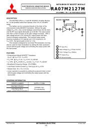
The <strong>MC34167</strong>, <strong>MC33167</strong> series are high performance fixed<br />
frequency power switching regulators that contain the primary<br />
functions required for dc−to−dc converters. This series was<br />
specifically designed to be incorporated in step−down and<br />
voltage−inverting configurations with a minimum number of external<br />
components and can also be used cost effectively in step−up<br />
applications.<br />
These devices consist of an internal temperature compensated<br />
reference, fixed frequency oscillator with on−chip timing components,<br />
latching pulse width modulator for single pulse metering, high gain<br />
error amplifier, and a high current output switch.<br />
Protective features consist of cycle−by−cycle current limiting,<br />
undervoltage lockout, and thermal shutdown. Also included is a low<br />
power standby mode that reduces power supply current to 36 A.<br />
Features<br />
• Output Switch Current in Excess of <strong>5.0</strong> A<br />
• Fixed Frequency Oscillator (72 kHz) with On−Chip Timing<br />
• Provides <strong>5.0</strong>5 V Output without External Resistor Divider<br />
• Precision 2% Reference<br />
• 0% to 95% Output Duty Cycle<br />
• Cycle−by−Cycle Current Limiting<br />
• Undervoltage Lockout with Hysteresis<br />
• Internal Thermal Shutdown<br />
• Operation from 7.5 V to 40 V<br />
• Standby Mode Reduces Power Supply Current to 36 A<br />
• Economical 5−Lead TO−220 Package with Two Optional Leadforms<br />
• Also Available in Surface Mount D 2 PAK Package<br />
• Moisture Sensitivity Level (MSL) Equals 1<br />
• Pb−Free Packages are Available<br />
Oscillator<br />
PWM<br />
Thermal<br />
S<br />
Q<br />
R<br />
3 5<br />
UVLO<br />
I LIMIT<br />
Reference<br />
EA<br />
This device contains 143 active transistors.<br />
Figure 1. Simplified Block Diagram<br />
(Step <strong>Down</strong> Application)<br />
4<br />
2<br />
1<br />
V in<br />
L<br />
V O<br />
<strong>5.0</strong>5 V/<br />
<strong>5.0</strong> A<br />
1<br />
1<br />
1<br />
5<br />
5<br />
TO−220<br />
TH SUFFIX<br />
CASE 314A<br />
Heatsink surface connected to Pin 3<br />
TO−220<br />
TV SUFFIX<br />
CASE 314B<br />
TO−220<br />
T SUFFIX<br />
CASE 314D<br />
5<br />
Pin 1. Voltage Feedback Input<br />
2. Switch Output<br />
3. Ground<br />
4. Input Voltage/V CC<br />
5. Compensation/Standby<br />
1<br />
D 2 PAK<br />
D2T SUFFIX<br />
CASE 936A<br />
5<br />
Heatsink surface (shown as<br />
terminal 6 in case outline<br />
drawing) is connected to Pin 3<br />
x = 3 or 4<br />
A = Assembly Location<br />
WL = Wafer Lot<br />
Y = Year<br />
WW = Work Week<br />
http://onsemi.com<br />
MARKING<br />
DIAGRAMS<br />
MC<br />
3x167T<br />
AWLYWW<br />
MC<br />
3x167T<br />
AWLYWW<br />
MC<br />
3x167T<br />
AWLYWW<br />
MC<br />
3x167T<br />
AWLYWW<br />
1 5<br />
ORDERING INFORMATION<br />
See detailed ordering and shipping information in the package<br />
dimensions section on page 17 of this data sheet.<br />
© Semiconductor Components Industries, LLC, 2004<br />
April, 2004 − Rev. 6<br />
1 Publication Order Number:<br />
<strong>MC34167</strong>/D
<strong>MC34167</strong>, <strong>MC33167</strong><br />
MAXIMUM RATINGS (Note 2)<br />
Rating Symbol Value Unit<br />
Power Supply Input Voltage V CC 40 V<br />
Switch Output Voltage Range V O(switch) −2.0 to + V in V<br />
Voltage Feedback and Compensation Input Voltage Range V FB, V Comp −1.0 to + 7.0 V<br />
Power Dissipation<br />
Case 314A, 314B and 314D (T A = +25°C) P D Internally Limited W<br />
Thermal Resistance, Junction−to−Ambient JA 65 °C/W<br />
Thermal Resistance, Junction−to−Case JC <strong>5.0</strong> °C/W<br />
Case 936A (D 2 PAK) (T A = +25°C) P D Internally Limited W<br />
Thermal Resistance, Junction−to−Ambient JA 70 °C/W<br />
Thermal Resistance, Junction−to−Case JC <strong>5.0</strong> °C/W<br />
Operating Junction Temperature T J +150 °C<br />
Operating Ambient Temperature (Note 3)<br />
<strong>MC34167</strong><br />
<strong>MC33167</strong><br />
T A<br />
0 to + 70<br />
− 40 to + 85<br />
°C<br />
Storage Temperature Range T stg − 65 to +150 °C<br />
Maximum ratings are those values beyond which device damage can occur. Maximum ratings applied to the device are individual stress limit<br />
values (not normal operating conditions) and are not valid simultaneously. If these limits are exceeded, device functional operation is not implied,<br />
damage may occur and reliability may be affected.<br />
1. Maximum package power dissipation limits must be observed to prevent thermal shutdown activation.<br />
2. This device series contains ESD protection and exceeds the following tests:<br />
Human Body Model 2000 V per MIL−STD−883, Method 3015.<br />
Machine Model Method 200 V.<br />
3. T low = 0°C for <strong>MC34167</strong> T high = + 70°C for <strong>MC34167</strong><br />
= −40°C for <strong>MC33167</strong> = + 85°C for <strong>MC33167</strong><br />
http://onsemi.com<br />
2
<strong>MC34167</strong>, <strong>MC33167</strong><br />
ELECTRICAL CHARACTERISTICS (V CC = 12 V, for typical values T A = +25°C, for min/max values T A is the operating ambient<br />
temperature range that applies (Notes 4, 5), unless otherwise noted.)<br />
OSCILLATOR<br />
Frequency (V CC = 7.5 V to 40 V)<br />
Characteristic Symbol Min Typ Max Unit<br />
T A = +25°C<br />
f OSC 65<br />
T A = T low to T high 62<br />
ERROR AMPLIFIER<br />
Voltage Feedback Input Threshold T A =+ 25°C<br />
V FB(th) 4.95<br />
T A = T low to T high 4.85<br />
4.2<br />
Line Regulation (V CC = 7.5 V to 40 V, T A = +25°C) Reg line − 0.03 0.078 %/V<br />
Input Bias Current (V FB = V FB(th) + 0.15 V) I IB − 0.15 1.0 A<br />
Power Supply Rejection Ratio (V CC = 10 V to 20 V, f = 120 Hz) PSRR 60 80 − dB<br />
Output Voltage Swing High State (I Source = 75 A, V FB = 4.5 V) V OH<br />
4.9<br />
− V<br />
Low State (I Sink = 0.4 mA, V FB = 5.5 V) V OL −<br />
1.6<br />
1.9<br />
72<br />
−<br />
<strong>5.0</strong>5<br />
−<br />
79<br />
81<br />
5.15<br />
5.20<br />
kHz<br />
V<br />
PWM COMPARATOR<br />
Duty Cycle (V CC = 20 V) Maximum (V FB = 0 V)<br />
Minimum (V Comp = 1.9 V)<br />
DC (max) 92<br />
DC (min) 0<br />
95<br />
0<br />
100<br />
0<br />
%<br />
SWITCH OUTPUT<br />
Output Voltage Source Saturation (V CC = 7.5 V, I Source = <strong>5.0</strong> A) V sat − (V CC −1.5) (V CC −1.8) V<br />
Off−State Leakage (V CC = 40 V, Pin 2 = GND) I sw(off) − 0 100 A<br />
Current Limit Threshold (V CC = 7.5 V) I pk(switch) 5.5 6.5 8.0 A<br />
Switching Times (V CC = 40 V, I pk = <strong>5.0</strong> A, L = 225 H, T A = +25°C)<br />
Output Voltage Rise Time<br />
Output Voltage Fall Time<br />
t r<br />
t f<br />
−<br />
−<br />
100<br />
50<br />
200<br />
100<br />
ns<br />
UNDERVOLTAGE LOCKOUT<br />
Startup Threshold (V CC Increasing, T A = +25°C) V th(UVLO) 5.5 5.9 6.3 V<br />
Hysteresis (V CC Decreasing, T A = +25°C) V H(UVLO) 0.6 0.9 1.2 V<br />
TOTAL DEVICE<br />
Power Supply Current (T A = +25°C )<br />
Standby (V CC = 12 V, V Comp < 0.15 V)<br />
Operating (V CC = 40 V, Pin 1 = GND for maximum duty cycle)<br />
4. Low duty cycle pulse techniques are used during test to maintain junction temperature as close to ambient as possible.<br />
5. T low = 0°C for <strong>MC34167</strong> T high = + 70°C for <strong>MC34167</strong><br />
= −40°C for <strong>MC33167</strong> = + 85°C for <strong>MC33167</strong><br />
I CC<br />
−<br />
−<br />
36<br />
40<br />
100<br />
60<br />
A<br />
mA<br />
http://onsemi.com<br />
3
<strong>MC34167</strong>, <strong>MC33167</strong><br />
VFB(th), VOLTAGE FEEDBACK INPUT THRESHOLD (V)<br />
5.25<br />
5.17<br />
<strong>5.0</strong>9<br />
<strong>5.0</strong>1<br />
4.93<br />
V CC = 12 V<br />
V FB(th) Max = 5.15 V<br />
V FB(th) Typ = <strong>5.0</strong>5 V<br />
V FB(th) Min = 4.95 V<br />
4.85<br />
−55 −25 0 25 50 75 100 125<br />
T A , AMBIENT TEMPERATURE (°C)<br />
Figure 2. Voltage Feedback Input Threshold<br />
versus Temperature<br />
IIB, INPUT BIAS CURRENT (nA)<br />
100<br />
80<br />
60<br />
40<br />
20<br />
V CC = 12 V<br />
V FB = V FB(th)<br />
0<br />
−55 −25 0 25 50 75 100 125<br />
T A , AMBIENT TEMPERATURE (°C)<br />
Figure 3. Voltage Feedback Input Bias<br />
Current versus Temperature<br />
AVOL , OPEN LOOP VOLTAGE GAIN (dB)<br />
100<br />
80<br />
60<br />
40<br />
20<br />
0<br />
−20<br />
10<br />
Gain<br />
V CC = 12 V<br />
V Comp = 3.25 V<br />
R L = 100 k<br />
T A = +25°C<br />
Phase<br />
100 1.0 k 10 k 100 k 1.0 M<br />
f, FREQUENCY (Hz)<br />
0<br />
30<br />
60<br />
90<br />
120<br />
150<br />
180<br />
10 M<br />
φ, EXCESS PHASE (DEGREES)<br />
Vsat, OUTPUT SATURATION VOLTAGE (V)<br />
2.0<br />
1.6<br />
1.2<br />
0.8<br />
0.4<br />
0<br />
0<br />
V CC = 12 V<br />
V FB = 5.5 V<br />
T A = +25°C<br />
0.4 0.8 1.2 1.6<br />
I Sink , OUTPUT SINK CURRENT (mA)<br />
2.0<br />
Figure 4. Error Amp Open Loop Gain and<br />
Phase versus Frequency<br />
Figure 5. Error Amp Output Saturation<br />
versus Sink Current<br />
∆ fOSC, OSCILLATOR FREQUENCY CHANGE (%)<br />
4.0<br />
0<br />
−4.0<br />
−8.0<br />
−12<br />
−55<br />
V CC = 12 V<br />
−25 0 25 50 75 100 125<br />
T A , AMBIENT TEMPERATURE (°C)<br />
Figure 6. Oscillator Frequency Change<br />
versus Temperature<br />
DC, SWITCH OUTPUT DUTY CYCLE (%)<br />
100<br />
80<br />
60<br />
40<br />
20<br />
0<br />
1.5<br />
V CC = 12 V<br />
T A = +25°C<br />
2.0 2.5 3.0 3.5 4.0<br />
V Comp , COMPENSATION VOLTAGE (V)<br />
Figure 7. Switch Output Duty Cycle<br />
versus Compensation Voltage<br />
4.5<br />
http://onsemi.com<br />
4
<strong>MC34167</strong>, <strong>MC33167</strong><br />
Vsat, SWITCH OUTPUT SOURCE SATURATION (V)<br />
0<br />
−0.5<br />
−1.0<br />
−1.5<br />
−2.0<br />
−2.5<br />
V CC<br />
T A = +25°C<br />
−3.0<br />
0 2.0 4.0 6.0 8.0<br />
I Source , SWITCH OUTPUT SOURCE CURRENT (A)<br />
Figure 8. Switch Output Source Saturation<br />
versus Source Current<br />
Vsw, SWITCH OUTPUT VOLTAGE (V)<br />
0<br />
−0.2<br />
−0.4<br />
−0.6<br />
−0.8<br />
−1.0<br />
V CC = 12 V<br />
Pin 5 = 2.0 V<br />
Pins 1, 3 = GND<br />
Pin 2 Driven Negative<br />
I sw = 10 mA<br />
GND<br />
I sw = 100 A<br />
−1.2<br />
−55 −25 0 25 50 75 100 125<br />
T A , AMBIENT TEMPERATURE (°C)<br />
Figure 9. Negative Switch Output Voltage<br />
versus Temperature<br />
Ipk(switch), CURRENT LIMIT THRESHOLD (A)<br />
7.2<br />
6.8<br />
6.4<br />
6.0<br />
V CC = 12 V<br />
Pins 1, 2, 3 = GND<br />
5.6<br />
−55 −25 0 25 50 75 100 125<br />
T A , AMBIENT TEMPERATURE (°C)<br />
µ A)<br />
ICC, SUPPLY CURRENT (<br />
160<br />
120<br />
80<br />
40<br />
0<br />
0<br />
Pin 4 = V CC<br />
Pins 1, 3, 5 = GND<br />
Pin 2 Open<br />
T A = +25°C<br />
10 20 30 40<br />
V CC , SUPPLY VOLTAGE (V)<br />
Figure 10. Switch Output Current Limit<br />
Threshold versus Temperature<br />
Figure 11. Standby Supply Current<br />
versus Supply Voltage<br />
Vth(UVLO), UNDERVOLTAGE LOCKOUT THRESHOLD (V)<br />
6.5<br />
6.0<br />
5.5<br />
<strong>5.0</strong><br />
4.5<br />
4.0<br />
−55<br />
Startup Threshold<br />
V CC Increasing<br />
Turn−Off Threshold<br />
V CC Decreasing<br />
−25 0 25 50 75 100 125<br />
T A , AMBIENT TEMPERATURE (°C)<br />
Figure 12. Undervoltage Lockout<br />
Thresholds versus Temperature<br />
ICC, SUPPLY CURRENT (mA)<br />
50<br />
40<br />
30<br />
20<br />
10<br />
Pin 4 = V CC<br />
Pins 1, 3 = GND<br />
Pins 2, 5 Open<br />
T A = +25°C<br />
0<br />
0 10 20 30 40<br />
V CC , SUPPLY VOLTAGE (V)<br />
Figure 13. Operating Supply Current<br />
versus Supply Voltage<br />
http://onsemi.com<br />
5
<strong>MC34167</strong>, <strong>MC33167</strong><br />
+<br />
Current<br />
Sense<br />
4<br />
Input Voltage/V CC<br />
C T<br />
Pulse Width<br />
Modulator<br />
Oscillator<br />
S<br />
R<br />
PWM Latch<br />
Q<br />
Undervoltage<br />
Lockout<br />
Switch<br />
Output<br />
2<br />
V in<br />
C in<br />
Thermal<br />
Shutdown<br />
100 A<br />
+<br />
<strong>5.0</strong>5 V<br />
Reference<br />
Error<br />
Amp<br />
+<br />
Voltage<br />
Feedback<br />
Input<br />
L<br />
GND<br />
3<br />
Compensation<br />
120<br />
5<br />
V<br />
1<br />
R O<br />
2<br />
C O<br />
C F R F<br />
R 1<br />
=<br />
Sink Only<br />
Positive True Logic<br />
Figure 14. <strong>MC34167</strong> Representative Block Diagram<br />
4.1 V<br />
Timing Capacitor C T<br />
Compensation<br />
2.3 V<br />
ON<br />
Switch Output<br />
OFF<br />
Figure 15. Timing Diagram<br />
http://onsemi.com<br />
6
<strong>MC34167</strong>, <strong>MC33167</strong><br />
INTRODUCTION<br />
The <strong>MC34167</strong>, <strong>MC33167</strong> series are monolithic power<br />
switching regulators that are optimized for dc−to−dc<br />
converter applications. These devices operate as fixed<br />
frequency, voltage mode regulators containing all the active<br />
functions required to directly implement step−down and<br />
voltage−inverting converters with a minimum number of<br />
external components. They can also be used cost effectively<br />
in step−up converter applications. Potential markets include<br />
automotive, computer, industrial, and cost sensitive<br />
consumer products. A description of each section of the<br />
device is given below with the representative block diagram<br />
shown in Figure 14.<br />
Oscillator<br />
The oscillator frequency is internally programmed to<br />
72 kHz by capacitor C T and a trimmed current source. The<br />
charge to discharge ratio is controlled to yield a 95%<br />
maximum duty cycle at the Switch Output. During the<br />
discharge of C T , the oscillator generates an internal blanking<br />
pulse that holds the inverting input of the AND gate high,<br />
disabling the output switch transistor. The nominal<br />
oscillator peak and valley thresholds are 4.1 V and 2.3 V<br />
respectively.<br />
Pulse Width Modulator<br />
The Pulse Width Modulator consists of a comparator with<br />
the oscillator ramp voltage applied to the noninverting input,<br />
while the error amplifier output is applied into the inverting<br />
input. Output switch conduction is initiated when C T is<br />
discharged to the oscillator valley voltage. As C T charges to<br />
a voltage that exceeds the error amplifier output, the latch<br />
resets, terminating output transistor conduction for the<br />
duration of the oscillator ramp−up period. This PWM/Latch<br />
combination prevents multiple output pulses during a given<br />
oscillator clock cycle. Figures 7 and 15 illustrate the switch<br />
output duty cycle versus the compensation voltage.<br />
Current Sense<br />
The <strong>MC34167</strong> series utilizes cycle−by−cycle current<br />
limiting as a means of protecting the output switch transistor<br />
from overstress. Each on cycle is treated as a separate<br />
situation. Current limiting is implemented by monitoring the<br />
output switch transistor current buildup during conduction,<br />
and upon sensing an overcurrent condition, immediately<br />
turning off the switch for the duration of the oscillator<br />
ramp−up period.<br />
The collector current is converted to a voltage by an<br />
internal trimmed resistor and compared against a reference<br />
by the Current Sense comparator. When the current limit<br />
threshold is reached, the comparator resets the PWM latch.<br />
The current limit threshold is typically set at 6.5 A.<br />
Figure 10 illustrates switch output current limit threshold<br />
versus temperature.<br />
Error Amplifier and Reference<br />
A high gain Error Amplifier is provided with access to the<br />
inverting input and output. This amplifier features a typical<br />
dc voltage gain of 80 dB, and a unity gain bandwidth of<br />
600 kHz with 70 degrees of phase margin (Figure 4). The<br />
noninverting input is biased to the internal <strong>5.0</strong>5 V reference<br />
and is not pinned out. The reference has an accuracy of<br />
± 2.0% at room temperature. To provide <strong>5.0</strong> V at the load,<br />
the reference is programmed 50 mV above <strong>5.0</strong> V to<br />
compensate for a 1.0% voltage drop in the cable and<br />
connector from the converter output. If the converter design<br />
requires an output voltage greater than <strong>5.0</strong>5 V, resistor R 1<br />
must be added to form a divider network at the feedback<br />
input as shown in Figures 14 and 19. The equation for<br />
determining the output voltage with the divider network is:<br />
Vout <strong>5.0</strong>5 R 2<br />
R1 1 <br />
External loop compensation is required for converter<br />
stability. A simple low−pass filter is formed by connecting<br />
a resistor (R 2 ) from the regulated output to the inverting<br />
input, and a series resistor−capacitor (R F , C F ) between Pins<br />
1 and 5. The compensation network component values<br />
shown in each of the applications circuits were selected to<br />
provide stability over the tested operating conditions. The<br />
step−down converter (Figure 19) is the easiest to<br />
compensate for stability. The step−up (Figure 21) and<br />
voltage−inverting (Figure 23) configurations operate as<br />
continuous conduction flyback converters, and are more<br />
difficult to compensate. The simplest way to optimize the<br />
compensation network is to observe the response of the<br />
output voltage to a step load change, while adjusting R F and<br />
C F for critical damping. The final circuit should be verified<br />
for stability under four boundary conditions. These<br />
conditions are minimum and maximum input voltages, with<br />
minimum and maximum loads.<br />
By clamping the voltage on the error amplifier output<br />
(Pin 5) to less than 150 mV, the internal circuitry will be<br />
placed into a low power standby mode, reducing the<br />
power supply current to 36 A with a 12 V supply voltage.<br />
Figure 11 illustrates the standby supply current versus<br />
supply voltage.<br />
The Error Amplifier output has a 100 A current source<br />
pull−up that can be used to implement soft−start. Figure 18<br />
shows the current source charging capacitor C SS through a<br />
series diode. The diode disconnects C SS from the feedback<br />
loop when the 1.0 M resistor charges it above the operating<br />
range of Pin 5.<br />
http://onsemi.com<br />
7
<strong>MC34167</strong>, <strong>MC33167</strong><br />
Switch Output<br />
The output transistor is designed to switch a maximum of<br />
40 V, with a minimum peak collector current of 5.5 A. When<br />
configured for step−down or voltage−inverting applications,<br />
as in Figures 19 and 23, the inductor will forward bias the<br />
output rectifier when the switch turns off. Rectifiers with a<br />
high forward voltage drop or long turn on delay time should<br />
not be used. If the emitter is allowed to go sufficiently<br />
negative, collector current will flow, causing additional<br />
device heating and reduced conversion efficiency. Figure 9<br />
shows that by clamping the emitter to 0.5 V, the collector<br />
current will be in the range of 100 A over temperature. A<br />
1N5825 or equivalent Schottky barrier rectifier is<br />
recommended to fulfill these requirements.<br />
Undervoltage Lockout<br />
An Undervoltage Lockout comparator has been<br />
incorporated to guarantee that the integrated circuit is fully<br />
functional before the output stage is enabled. The internal<br />
reference voltage is monitored by the comparator which<br />
enables the output stage when V CC exceeds 5.9 V. To prevent<br />
erratic output switching as the threshold is crossed, 0.9 V of<br />
hysteresis is provided.<br />
Thermal Protection<br />
Internal Thermal Shutdown circuitry is provided to protect<br />
the integrated circuit in the event that the maximum junction<br />
temperature is exceeded. When activated, typically at 170°C,<br />
the latch is forced into a ‘reset’ state, disabling the output<br />
switch. This feature is provided to prevent catastrophic<br />
failures from accidental device overheating. It is not<br />
intended to be used as a substitute for proper heatsinking.<br />
The <strong>MC34167</strong> is contained in a 5−lead TO−220 type package.<br />
The tab of the package is common with the center pin (Pin 3)<br />
and is normally connected to ground.<br />
Do not attempt to construct a converter on wire−wrap<br />
or plug−in prototype boards. Special care should be taken<br />
to separate ground paths from signal currents and ground<br />
paths from load currents. All high current loops should be<br />
kept as short as possible using heavy copper runs to<br />
minimize ringing and radiated EMI. For best operation, a<br />
DESIGN CONSIDERATIONS<br />
tight component layout is recommended. Capacitors C in ,<br />
C O , and all feedback components should be placed as close<br />
to the IC as physically possible. It is also imperative that the<br />
Schottky diode connected to the Switch Output be located as<br />
close to the IC as possible.<br />
http://onsemi.com<br />
8
<strong>MC34167</strong>, <strong>MC33167</strong><br />
1<br />
+<br />
100 A<br />
Error<br />
Amp<br />
+<br />
100 A<br />
Error<br />
Amp<br />
120<br />
V in<br />
120<br />
1<br />
Compensation 5<br />
R 1<br />
Compensation 5<br />
R 1<br />
I = Standby Mode V Shutdown = V Zener + 0.7<br />
Figure 16. Low Power Standby Circuit<br />
Figure 17. Over Voltage Shutdown Circuit<br />
+<br />
100 A<br />
Error<br />
Amp<br />
120<br />
1<br />
Compensation 5<br />
D 2<br />
D 1<br />
R 1<br />
1.0 M<br />
C ss<br />
t Soft−Start ≈ 35,000 C ss<br />
Figure 18. Soft−Start Circuit<br />
http://onsemi.com<br />
9
<strong>MC34167</strong>, <strong>MC33167</strong><br />
V in<br />
12 V<br />
+<br />
PWM<br />
Oscillator<br />
S<br />
R<br />
Q<br />
ILIMIT<br />
UVLO<br />
4<br />
+<br />
C in<br />
330<br />
Q 1<br />
2 D 1<br />
1N5825<br />
3<br />
Thermal<br />
5<br />
+<br />
C<br />
R 1<br />
Reference<br />
+<br />
EA<br />
R 2<br />
1 6.8 k<br />
C F R F<br />
O<br />
4700<br />
+<br />
L<br />
190 H<br />
V O<br />
<strong>5.0</strong>5 V/<strong>5.0</strong> A<br />
0.1<br />
68 k<br />
Test Conditions Results<br />
Line Regulation V in = 10 V to 36 V, I O = <strong>5.0</strong> A 4.0 mV = ± 0.039%<br />
Load Regulation V in = 12 V, I O = 0.25 A to <strong>5.0</strong> A 1.0 mV = ± 0.01%<br />
Output Ripple V in = 12 V, I O = <strong>5.0</strong> A 20 mV pp<br />
Short Circuit Current V in = 12 V, R L = 0.1 6.5 A<br />
Efficiency<br />
V in = 12 V, I O = <strong>5.0</strong> A<br />
V in = 24 V, I O = <strong>5.0</strong> A<br />
78.9%<br />
82.6%<br />
L = Coilcraft M1496−A or General Magnetics Technology GMT−0223, 42 turns of #16 A WG<br />
on Magnetics Inc. 58350−A2 core. Heatsink = AAVID Engineering Inc. 5903B, or 5930B.<br />
The Step−<strong>Down</strong> Converter application is shown in Figure 19 . The output switch transistor Q 1 interrupts the input voltage, generating a<br />
squarewave at the LC O filter input. The filter averages the squarewaves, producing a dc output voltage that can be set to any level between<br />
V in and V ref by controlling the percent conduction time of Q 1 to that of the total oscillator cycle time. If the converter design requires an output<br />
voltage greater than <strong>5.0</strong>5 V, resistor R 1 must be added to form a divider network at the feedback input.<br />
Figure 19. Step−<strong>Down</strong> Converter<br />
3.0″<br />
<strong>MC34167</strong> STEP−DOWN<br />
1.9″<br />
V in<br />
+ −<br />
C F<br />
C O<br />
ÉÉÉÉÉ<br />
ÉÉÉÉÉ<br />
RF<br />
R2<br />
C in<br />
D1<br />
L<br />
+<br />
V O<br />
− +<br />
R1<br />
ÉÉÉÉÉ<br />
ÉÉÉÉÉ<br />
+<br />
ÉÉÉÉÉ<br />
ÉÉÉÉÉ<br />
(Bottom View)<br />
(Top View)<br />
Figure 20. Step−<strong>Down</strong> Converter Printed Circuit Board and Component Layout<br />
ÉÉÉ<br />
http://onsemi.com<br />
10
<strong>MC34167</strong>, <strong>MC33167</strong><br />
V in<br />
12 V<br />
+<br />
PWM<br />
Oscillator<br />
S<br />
R<br />
Q<br />
ILIMIT<br />
UVLO<br />
4<br />
2<br />
+<br />
C in<br />
330<br />
Q 1<br />
D 1<br />
1N5825<br />
L<br />
190 H<br />
Thermal<br />
+<br />
Reference<br />
EA<br />
+<br />
1<br />
D 4<br />
1N4148<br />
D 3<br />
1N967A<br />
R 2<br />
6.8 k<br />
*R G<br />
620<br />
C O<br />
2200<br />
Q 2<br />
MTP3055EL<br />
D 2<br />
1N5822<br />
V<br />
+ O<br />
28 V/0.9 A<br />
3<br />
5<br />
C F R F<br />
R 1<br />
*Gate resistor R G , zener diode D 3 , and diode D 4 are required only when V in is greater than 20 V.<br />
0.47<br />
4.7 k<br />
1.5 k<br />
Test Conditions Results<br />
Line Regulation V in = 10 V to 24 V, I O = 0.9 A 10 mV = ± 0.017%<br />
Load Regulation V in = 12 V, I O = 0.1 A to 0.9 A 30 mV = ± 0.053%<br />
Output Ripple V in = 12 V, I O = 0.9 A 140 mV pp<br />
Short Circuit Current V in = 12 V, R L = 0.1 6.0 A<br />
Efficiency<br />
V in = 12 V, I O = 0.9 A<br />
V in = 24 V, I O = 0.9 A<br />
80.1%<br />
87.8%<br />
L = Coilcraft M1496−A or General Magnetics Technology GMT−0223, 42 turns of #16 AWG on<br />
Magnetics Inc. 58350−A2 core.<br />
Heatsink = AAVID Engineering Inc. <strong>MC34167</strong>: 5903B, or 5930B MTP3055EL: 5925B<br />
Figure 21 shows that the <strong>MC34167</strong> can be configured as a step−up/down converter with the addition of an external power MOSFET. Energy<br />
is stored in the inductor during the ON time of transistors Q 1 and Q 2 . During the OFF time, the energy is transferred, with respect to ground,<br />
to the output filter capacitor and load. This circuit configuration has two significant advantages over the basic step−up converter circuit. The first<br />
advantage is that output short circuit protection is provided by the <strong>MC34167</strong>, since Q 1 is directly in series with V in and the load. Second, the<br />
output voltage can be programmed to be less than V in . Notice that during the OFF time, the inductor forward biases diodes D 1 and D 2 , transferring<br />
its energy with respect to ground rather than with respect to V in . When operating with V in greater than 20 V, a gate protection network is required<br />
for the MOSFET. The network consists of components R G , D 3 , and D 4 .<br />
3.45<br />
″<br />
Figure 21. Step−Up/<strong>Down</strong> Converter<br />
<strong>MC34167</strong> STEP UP-DOWN<br />
1.9″<br />
V in<br />
+ −<br />
V O<br />
− +<br />
C O<br />
ÎÎÎÎÎ<br />
C F<br />
RF<br />
R2<br />
C in<br />
D1<br />
L<br />
+<br />
R1<br />
ÎÎÎÎÎ<br />
ÎÎÎÎÎ<br />
ÎÎÎÎÎ<br />
+<br />
D2<br />
Î<br />
ÎÎ<br />
ÎÎ<br />
ÎÎ<br />
R G<br />
Î<br />
D3<br />
Q2<br />
(Bottom<br />
ÎÎÎÎÎ<br />
View)<br />
(Top View)<br />
Figure 22. Step−Up/<strong>Down</strong> Converter Printed Circuit Board and Component Layout<br />
http://onsemi.com<br />
11
<strong>MC34167</strong>, <strong>MC33167</strong><br />
V in<br />
12 V<br />
+<br />
PWM<br />
Oscillator<br />
S<br />
R<br />
Q<br />
ILIMIT<br />
UVLO<br />
4<br />
Q 1<br />
+<br />
2<br />
C in<br />
330<br />
L<br />
190 H<br />
Thermal<br />
D 1<br />
1N5825<br />
3<br />
5<br />
+<br />
Reference<br />
EA<br />
+<br />
1<br />
R 1<br />
2.4 k<br />
C 1<br />
+<br />
V O<br />
−12 V/1.7 A<br />
C O<br />
4700<br />
0.47<br />
C F R F<br />
R 2<br />
4.7 k<br />
3.3 k<br />
0.047<br />
Test Conditions Results<br />
Line Regulation V in = 10 V to 24 V, I O = 1.7 A 15 mV = ± 0.61%<br />
Load Regulation V in = 12 V, I O = 0.1 A to 1.7 A 4.0 mV = ± 0.020%<br />
Output Ripple V in = 12 V, I O = 1.7 A 78 mV pp<br />
Short Circuit Current V in = 12 V, R L = 0.1 5.7 A<br />
Efficiency<br />
V in = 12 V, I O = 1.7 A<br />
V in = 24 V, I O = 1.7 A<br />
79.5%<br />
86.2%<br />
L = Coilcraft M1496−A or General Magnetics Technology GMT−0223, 42 turns of #16 AWG on<br />
Magnetics Inc. 58350−A2 core. Heatsink = AAVID Engineering Inc. 5903B, or 5930B.<br />
Two potential problems arise when designing the standard voltage−inverting converter with the <strong>MC34167</strong>. First, the Switch Output emitter is<br />
limited to −1.5 V with respect to the ground pin and second, the Error Amplifier’s noninverting input is internally committed to the reference and<br />
is not pinned out. Both of these problems are resolved by connecting the IC ground pin to the converter’s negative output as shown in Figure 23.<br />
This keeps the emitter of Q 1 positive with respect to the ground pin and has the effect of reversing the Error Amplifier inputs. Note that the voltage<br />
drop across R 1 is equal to <strong>5.0</strong>5 V when the output is in regulation.<br />
3.0″<br />
Figure 23. Voltage−<strong>Inverting</strong> Converter<br />
+<br />
+<br />
+<br />
<strong>MC34167</strong><br />
VOLTAGE-INVERTING<br />
1.9″<br />
V O<br />
− +<br />
V in<br />
+ −<br />
RF<br />
R2<br />
R1<br />
C1<br />
C O<br />
ÎÎÎÎÎÎ<br />
ÎÎÎÎÎÎ<br />
C in<br />
D1<br />
L<br />
C F<br />
(Bottom View)<br />
+<br />
+<br />
ÎÎÎÎÎÎ<br />
ÎÎÎÎÎÎ<br />
ÎÎÎÎÎÎ<br />
(Top View)<br />
ÎÎÎÎÎÎ<br />
Figure 24. Voltage−<strong>Inverting</strong> Converter Printed Circuit Board and Component Layout<br />
+<br />
http://onsemi.com<br />
12
<strong>MC34167</strong>, <strong>MC33167</strong><br />
V in<br />
24 V<br />
+<br />
PWM<br />
Oscillator<br />
S<br />
R<br />
Q<br />
ILIMIT<br />
UVLO<br />
4<br />
2<br />
+<br />
1000<br />
1N5825<br />
MUR110<br />
+<br />
1000<br />
V O3<br />
−12 V/200 mA<br />
Thermal<br />
+<br />
Reference<br />
EA<br />
+<br />
1<br />
6.8 k<br />
T1<br />
+<br />
1000<br />
MUR110<br />
V O1<br />
<strong>5.0</strong> V/3.0 A<br />
+<br />
1000<br />
V O2<br />
12 V/250 mA<br />
3<br />
5<br />
0.1<br />
68 k<br />
Figure 25. Triple Output Converter<br />
Line Regulation<br />
Load Regulation<br />
Output Ripple<br />
Short Circuit Current<br />
Tests Conditions Results<br />
<strong>5.0</strong> V<br />
12 V<br />
−12 V<br />
<strong>5.0</strong> V<br />
12 V<br />
−12 V<br />
<strong>5.0</strong> V<br />
12 V<br />
−12 V<br />
<strong>5.0</strong> V<br />
12 V<br />
−12 V<br />
V in = 15 V to 30 V, I O1 = 3.0 A, I O2 = 250 mA, I O3 = 200 mA 3.0 mV = ± 0.029%<br />
572 mV = ± 2.4%<br />
711 mV = ± 2.9%<br />
V in = 24 V, I O1 = 30 mA to 3.0 A, I O2 = 250 mA, I O3 = 200 mA<br />
V in = 24 V, I O1 = 3.0 A, I O2 = 100 mA to 250 mA, I O3 = 200 mA<br />
V in = 24 V, I O1 = 3.0 A, I O2 = 250 mA, I O3 = 75 mA to 200 mA<br />
V in = 24 V, I O1 = 3.0 A, I O2 = 250 mA, I O3 = 200 mA<br />
V in = 24 V, R L = 0.1 <br />
1.0 mV = ± 0.009%<br />
409 mV = ±1.5%<br />
528 mV = ± 2.0%<br />
75 mV pp<br />
20 mV pp<br />
20 mV pp<br />
6.5 A<br />
2.7 A<br />
2.2 A<br />
Efficiency TOTAL V in = 24 V, I O1 = 3.0 A, I O2 = 250 mA, I O3 = 200 mA 84.2%<br />
T1 = Primary: Coilcraft M1496−A or General Magnetics Technology GMT−0223, 42 turns of #16 AWG on Magnetics Inc. 58350−A2 core.<br />
T1 = Secondary: V O2 − 69 turns of #26 AWG<br />
T1 = Secondary: V O3 − 104 turns of #28 AWG<br />
Heatsink = AAVID Engineering Inc. 5903B, or 5930B.<br />
Multiple auxiliary outputs can easily be derived by winding secondaries on the main output inductor to form a transformer. The secondaries<br />
must be connected so that the energy is delivered to the auxiliary outputs when the Switch Output turns off. During the OFF time, the voltage<br />
across the primary winding is regulated by the feedback loop, yielding a constant Volts/Turn ratio. The number of turns for any given secondary<br />
voltage can be calculated by the following equation:<br />
# TURNS(SEC) V O(SEC) VF(SEC)<br />
V O(PRI)VF(PRI)<br />
<br />
#TURNS(PRI)<br />
Note that the 12 V winding is stacked on top of the <strong>5.0</strong> V output. This reduces the number of secondary turns and improves lead regulation. For<br />
best auxiliary regulation, the auxiliary outputs should be less than 33% of the total output power.<br />
http://onsemi.com<br />
13
<strong>MC34167</strong>, <strong>MC33167</strong><br />
+<br />
ILIMIT<br />
4<br />
PWM<br />
Oscillator<br />
Thermal<br />
S<br />
R<br />
Q<br />
+<br />
UVLO<br />
Reference<br />
EA<br />
Q 1<br />
+<br />
2<br />
1<br />
22<br />
0.01<br />
1N5825<br />
D 1<br />
Z 1<br />
R 1<br />
VO R 1 <strong>5.0</strong>5<br />
R2 0.7<br />
L<br />
MUR415<br />
MTP<br />
3055E<br />
2N3906<br />
V O<br />
+36 V/0.3 A<br />
+<br />
1000<br />
R 1<br />
36 k<br />
6.8 k<br />
V in<br />
−12 V<br />
3<br />
+<br />
1000<br />
5<br />
0.22 470 k<br />
0.002<br />
R 2<br />
5.1 k<br />
*Gate resistor R G , zener diode D 3 , and diode D 4 are required only when V in is greater than 20 V.<br />
Test Conditions Results<br />
Line Regulation V in = −10 V to − 20 V, I O = 0.3 A 266 mV = ± 0.38%<br />
Load Regulation V in = −12 V, I O = 0.03 A to 0.3 A 7.90 mV = ±1.1%<br />
Output Ripple V in = −12 V, I O = 0.3 A 100 mV pp<br />
Efficiency V in = −12 V, I O = 0.3 A 78.4%<br />
L = General Magnetics Technology GMT−0223, 42 turns of #16 A WG on Magnetics Inc.<br />
58350−A2 core. Heatsink = AAVID Engineering Inc. 5903B or 5930B<br />
Figure 26. Negative Input/Positive Output Regulator<br />
+<br />
PWM<br />
Oscillator<br />
S<br />
R<br />
Q<br />
ILIMIT<br />
UVLO<br />
4<br />
2<br />
+<br />
V in<br />
18 V<br />
1000<br />
1N5825<br />
Thermal<br />
+<br />
Reference<br />
Brush<br />
Motor<br />
EA<br />
+<br />
1<br />
5.6 k<br />
+<br />
1.0 k<br />
47<br />
50 k<br />
Faster<br />
3<br />
5<br />
0.1<br />
56 k<br />
Test Conditions Results<br />
Low Speed Line Regulation V in = 12 V to 24 V 1760 RPM ±1%<br />
High Speed Line Regulation V in = 12 V to 24 V 3260 RPM ± 6%<br />
Figure 27. Variable Motor Speed Control with EMF Feedback Sensing<br />
http://onsemi.com<br />
14
<strong>MC34167</strong>, <strong>MC33167</strong><br />
0.001<br />
T1<br />
MBR20100CT<br />
115 VAC<br />
RFI<br />
Filter<br />
1N5404<br />
+<br />
220<br />
MJE13005<br />
0.001<br />
0.001<br />
<strong>MC34167</strong><br />
+ +<br />
1000 Step−<strong>Down</strong><br />
Converter<br />
Output 1<br />
100k<br />
50<br />
0.047<br />
1N4937<br />
T 2<br />
0.01<br />
MBR20100CT<br />
0.001<br />
1000 + <strong>MC34167</strong><br />
Step−<strong>Down</strong><br />
+<br />
Converter<br />
Output 2<br />
3.3<br />
1N4003<br />
+<br />
100<br />
0.001<br />
MBR20100CT<br />
0.001<br />
1000 + <strong>MC34167</strong><br />
Step−<strong>Down</strong><br />
+<br />
Converter<br />
Output 3<br />
T 1 = Core and Bobbin − Coilcraft PT3595<br />
T 1 = Primary − 104 turns #26 AWG<br />
T 1 = Base Drive − 3 turns #26 AWG<br />
T 1 = Secondaries − 16 turns #16 AWG<br />
T 1 = Total Gap − 0.002,<br />
T 2 = Core − TDK T6 x 1.5 x 3 H5C2<br />
T 2 = 14 turns center tapped #30 AWG<br />
T 2 = Heatsink = AAVID Engineering Inc.<br />
T 2 = <strong>MC34167</strong> and MJE13005 − 5903B<br />
T 2 = MBR20100CT − 5925B<br />
The <strong>MC34167</strong> can be used cost effectively in off−line applications even though it is limited to a maximum input voltage of 40 V. Figure 28 shows<br />
a simple and ef ficient method for converting the AC line voltage down to 24 V . This preconverter has a total power rating of 12 5 W with a<br />
conversion efficiency of 90%. Transformer T 1 provides output isolation from the AC line and isolation between each of the secondaries. The<br />
circuit self−oscillates at 50 kHz and is controlled by the saturation characteristics of T 2 . Multiple <strong>MC34167</strong> post regulators can be used to provide<br />
accurate independently regulated outputs for a distributed power system.<br />
Figure 28. Off−Line Preconverter<br />
R θJA , THERMAL RESISTANCE<br />
JUNCTION-TO-AIR ( ° C/W)<br />
80<br />
70<br />
60<br />
50<br />
40<br />
Free Air<br />
Mounted<br />
Vertically<br />
Minimum<br />
Size Pad<br />
P D(max) for T A = +50°C<br />
R JA<br />
30<br />
1.0<br />
0 <strong>5.0</strong> 10 15 20 25 30<br />
L, LENGTH OF COPPER (mm)<br />
L<br />
2.0 oz. Copper<br />
L<br />
ÎÎÎÎ<br />
ÎÎÎÎ<br />
ÎÎÎÎ<br />
ÎÎÎÎ<br />
3.5<br />
3.0<br />
2.5<br />
2.0<br />
1.5<br />
P D<br />
, MAXIMUM POWER DISSIPATION (W)<br />
Figure 29. D 2 PAK Thermal Resistance and Maximum<br />
Power Dissipation versus P.C.B. Copper Length<br />
http://onsemi.com<br />
15
<strong>MC34167</strong>, <strong>MC33167</strong><br />
Table 1. Design Equations<br />
Calculation Step−<strong>Down</strong> Step−Up/<strong>Down</strong> Voltage−<strong>Inverting</strong><br />
ton<br />
toff<br />
(Notes 1, 2)<br />
Vout VF<br />
Vin Vsat Vout<br />
Vout VF1 VF2<br />
Vin VsatQ1 VsatQ2<br />
|Vout| VF<br />
Vin Vsat<br />
t on<br />
Duty Cycle<br />
(Note 3)<br />
ton<br />
toff<br />
fosc t on<br />
toff 1<br />
ton<br />
toff<br />
fosc t on<br />
toff 1<br />
ton<br />
toff<br />
fosc t on<br />
toff 1<br />
t on f osc t on f osc t on f osc<br />
I L avg I out Iout t on<br />
toff 1<br />
I pk(switch)<br />
L<br />
I Lavg I L<br />
2<br />
V in Vsat Voutton<br />
IL<br />
<br />
V ripple(pp) I L 1<br />
8foscCo 2 (ESR)2<br />
IL avg I L<br />
2<br />
V in VsatQ1 VsatQ2ton<br />
IL<br />
t on<br />
<br />
toff 1 1<br />
foscCo 2 (ESR)2<br />
I out t on<br />
toff 1<br />
IL avg I L<br />
2<br />
V in Vsatton<br />
IL<br />
t on<br />
toff 1 1<br />
f oscCo 2 (ESR)2<br />
V out Vref R 2<br />
R1 1 V ref R 2<br />
R1 1 V ref R 2<br />
R1 1<br />
1. V sat − Switch Output source saturation voltage, refer to Figure 8.<br />
2. V F − Output rectifier forward voltage drop. Typical value for 1N5822 Schottky barrier rectifier is 0.35 V.<br />
3. Duty cycle is calculated at the minimum operating input voltage and must not exceed the guaranteed minimum DC (max) specification of 0.92.<br />
The following converter characteristics must be chosen:<br />
V out − Desired output voltage.<br />
I out − Desired output current.<br />
I L − Desired peak−to−peak inductor ripple current. For maximum output current especially when the duty cycle is greater than 0.5,<br />
it is suggested that I L be chosen minimum current limit threshold of 5.5 A. If the design goal is to use a minimum inductance<br />
value, let I L = 2 (I L avg ). This will proportionally reduce the converter’s output current capability.<br />
V ripple(pp) − Desired peak−to−peak output ripple voltage. For best performance, the ripple voltage should be kept to less than 2% of V out .<br />
Capacitor C O should be a low equivalent series resistance (ESR) electrolytic designed for switching regulator applications.<br />
http://onsemi.com<br />
16
<strong>MC34167</strong>, <strong>MC33167</strong><br />
Device<br />
<strong>MC33167</strong>D2T<br />
<strong>MC33167</strong>T<br />
<strong>MC33167</strong>TG<br />
ORDERING INFORMATION<br />
Operating<br />
Temperature Range Package Shipping †<br />
T A =−40° to +85°C<br />
D 2 PAK (Surface Mount)<br />
TO−220 (Straight Lead)<br />
TO−220 (Straight Lead)<br />
(Pb−Free)<br />
50 Units/Rail<br />
50 Units/Rail<br />
<strong>MC33167</strong>TH<br />
<strong>MC33167</strong>TV<br />
<strong>MC33167</strong>TVG<br />
T A =−40° to +85°C<br />
TO−220 (Horizontal Mount)<br />
TO−220 (Vertical Mount)<br />
TO−220 (Vertical Mount)<br />
(Pb−Free)<br />
50 Units/Rail<br />
50 Units/Rail<br />
<strong>MC34167</strong>D2T<br />
<strong>MC34167</strong>T<br />
<strong>MC34167</strong>TH<br />
<strong>MC34167</strong>TV<br />
<strong>MC34167</strong>TVG<br />
T A = 0° to +70°C<br />
D 2 PAK (Surface Mount)<br />
TO−220 (Straight Lead)<br />
TO−220 (Horizontal Mount)<br />
TO−220 (Vertical Mount)<br />
TO−220 (Vertical Mount)<br />
(Pb−Free)<br />
†For information on tape and reel specifications, including part orientation and tape sizes, please refer to our T<br />
Specifications Brochure, BRD8011/D.<br />
50 Units/Rail<br />
50 Units/Rail<br />
ape and Reel Packaging<br />
http://onsemi.com<br />
17
<strong>MC34167</strong>, <strong>MC33167</strong><br />
PACKAGE DIMENSIONS<br />
TO−220<br />
TH SUFFIX<br />
CASE 314A−03<br />
ISSUE E<br />
Q<br />
B<br />
−P−<br />
OPTIONAL<br />
CHAMFER<br />
E<br />
C<br />
−T− SEATING<br />
PLANE<br />
NOTES:<br />
1. DIMENSIONING AND TOLERANCING PER ANSI<br />
Y14.5M, 1982.<br />
2. CONTROLLING DIMENSION: INCH.<br />
3. DIMENSION D DOES NOT INCLUDE<br />
INTERCONNECT BAR (DAMBAR) PROTRUSION.<br />
DIMENSION D INCLUDING PROTRUSION SHALL<br />
NOT EXCEED 0.043 (1.092) MAXIMUM.<br />
U<br />
5X D<br />
0.014 (0.356) M T<br />
G<br />
P<br />
A<br />
M<br />
L<br />
S<br />
F<br />
K<br />
5X J<br />
INCHES MILLIMETERS<br />
DIM MIN MAX MIN MAX<br />
A 0.572 0.613 14.529 15.570<br />
B 0.390 0.415 9.906 10.541<br />
C 0.170 0.180 4.318 4.572<br />
D 0.025 0.038 0.635 0.965<br />
E 0.048 0.055 1.219 1.397<br />
F 0.570 0.585 14.478 14.859<br />
G 0.067 BSC 1.702 BSC<br />
J 0.015 0.025 0.381 0.635<br />
K 0.730 0.745 18.542 18.923<br />
L 0.320 0.365 8.128 9.271<br />
Q 0.140 0.153 3.556 3.886<br />
S 0.210 0.260 5.334 6.604<br />
U 0.468 0.505 11.888 12.827<br />
TO−220<br />
TV SUFFIX<br />
CASE 314B−05<br />
ISSUE J<br />
K<br />
Q<br />
F<br />
U<br />
5X D<br />
B<br />
−P−<br />
0.10 (0.254) M T P M<br />
G<br />
A<br />
OPTIONAL<br />
CHAMFER<br />
S<br />
5X J<br />
0.24 (0.610) M T<br />
L<br />
E<br />
N<br />
C<br />
H<br />
W<br />
V<br />
−T− SEATING<br />
PLANE<br />
NOTES:<br />
1. DIMENSIONING AND TOLERANCING PER ANSI<br />
Y14.5M, 1982.<br />
2. CONTROLLING DIMENSION: INCH.<br />
3. DIMENSION D DOES NOT INCLUDE<br />
INTERCONNECT BAR (DAMBAR) PROTRUSION.<br />
DIMENSION D INCLUDING PROTRUSION SHALL<br />
NOT EXCEED 0.043 (1.092) MAXIMUM.<br />
INCHES MILLIMETERS<br />
DIM MIN MAX MIN MAX<br />
A 0.572 0.613 14.529 15.570<br />
B 0.390 0.415 9.906 10.541<br />
C 0.170 0.180 4.318 4.572<br />
D 0.025 0.038 0.635 0.965<br />
E 0.048 0.055 1.219 1.397<br />
F 0.850 0.935 21.590 23.749<br />
G 0.067 BSC 1.702 BSC<br />
H 0.166 BSC 4.216 BSC<br />
J 0.015 0.025 0.381 0.635<br />
K 0.900 1.100 22.860 27.940<br />
L 0.320 0.365 8.128 9.271<br />
N 0.320 BSC 8.128 BSC<br />
Q 0.140 0.153 3.556 3.886<br />
S −−− 0.620 −−− 15.748<br />
U 0.468 0.505 11.888 12.827<br />
V −−− 0.735 −−− 18.669<br />
W 0.090 0.110 2.286 2.794<br />
http://onsemi.com<br />
18
<strong>MC34167</strong>, <strong>MC33167</strong><br />
PACKAGE DIMENSIONS<br />
TO−220<br />
T SUFFIX<br />
CASE 314D−04<br />
ISSUE E<br />
−Q−<br />
B<br />
E<br />
C<br />
−T−<br />
SEATING<br />
PLANE<br />
NOTES:<br />
1. DIMENSIONING AND TOLERANCING PER ANSI<br />
Y14.5M, 1982.<br />
2. CONTROLLING DIMENSION: INCH.<br />
3. DIMENSION D DOES NOT INCLUDE<br />
INTERCONNECT BAR (DAMBAR) PROTRUSION.<br />
DIMENSION D INCLUDING PROTRUSION SHALL<br />
NOT EXCEED 10.92 (0.043) MAXIMUM.<br />
K<br />
D 5 PL<br />
U<br />
12345<br />
G<br />
0.356 (0.014) M T<br />
A<br />
Q<br />
M<br />
L<br />
J<br />
H<br />
INCHES MILLIMETERS<br />
DIM MIN MAX MIN MAX<br />
A 0.572 0.613 14.529 15.570<br />
B 0.390 0.415 9.906 10.541<br />
C 0.170 0.180 4.318 4.572<br />
D 0.025 0.038 0.635 0.965<br />
E 0.048 0.055 1.219 1.397<br />
G 0.067 BSC 1.702 BSC<br />
H 0.087 0.112 2.210 2.845<br />
J 0.015 0.025 0.381 0.635<br />
K 0.990 1.045 25.146 26.543<br />
L 0.320 0.365 8.128 9.271<br />
Q 0.140 0.153 3.556 3.886<br />
U 0.105 0.117 2.667 2.972<br />
http://onsemi.com<br />
19
<strong>MC34167</strong>, <strong>MC33167</strong><br />
D 2 PAK<br />
D2T SUFFIX<br />
CASE 936A−02<br />
ISSUE B<br />
B<br />
K<br />
A<br />
1 2 3<br />
4 5<br />
S<br />
OPTIONAL<br />
CHAMFER<br />
H<br />
−T−<br />
E<br />
V<br />
TERMINAL 6<br />
U<br />
NOTES:<br />
1. DIMENSIONING AND TOLERANCING PER ANSI<br />
Y14.5M, 1982.<br />
2. CONTROLLING DIMENSION: INCH.<br />
3. TAB CONTOUR OPTIONAL WITHIN DIMENSIONS<br />
A AND K.<br />
4. DIMENSIONS U AND V ESTABLISH A MINIMUM<br />
MOUNTING SURFACE FOR TERMINAL 6.<br />
5. DIMENSIONS A AND B DO NOT INCLUDE MOLD<br />
FLASH OR GATE PROTRUSIONS. MOLD FLASH<br />
AND GATE PROTRUSIONS NOT TO EXCEED<br />
0.025 (0.635) MAXIMUM.<br />
D<br />
0.010 (0.254) M T<br />
C<br />
G<br />
M L<br />
N<br />
P<br />
R<br />
SOLDERING FOOTPRINT*<br />
INCHES MILLIMETERS<br />
DIM MIN MAX MIN MAX<br />
A 0.386 0.403 9.804 10.236<br />
B 0.356 0.368 9.042 9.347<br />
C 0.170 0.180 4.318 4.572<br />
D 0.026 0.036 0.660 0.914<br />
E 0.045 0.055 1.143 1.397<br />
G 0.067 BSC 1.702 BSC<br />
H 0.539 0.579 13.691 14.707<br />
K 0.050 REF 1.270 REF<br />
L 0.000 0.010 0.000 0.254<br />
M 0.088 0.102 2.235 2.591<br />
N 0.018 0.026 0.457 0.660<br />
P 0.058 0.078 1.473 1.981<br />
R 5 REF<br />
5 REF<br />
S 0.116 REF 2.946 REF<br />
U 0.200 MIN <strong>5.0</strong>80 MIN<br />
V 0.250 MIN 6.350 MIN<br />
8.38<br />
0.33<br />
10.66<br />
0.42<br />
1.016<br />
0.04<br />
<strong>5.0</strong>8<br />
0.20<br />
17.02<br />
0.67<br />
3.05<br />
0.12<br />
SCALE 3:1<br />
mm<br />
inches <br />
*For additional information on our Pb−Free strategy and soldering<br />
details, please download the ON Semiconductor Soldering and<br />
Mounting Techniques Reference Manual, SOLDERRM/D.<br />
ON Semiconductor and are registered trademarks of Semiconductor Components Industries, LLC (SCILLC). SCILLC reserves the right to make changes without further notice<br />
to any products herein. SCILLC makes no warranty, representation or guarantee regarding the suitability of its products for any particular purpose, nor does SCILLC assume any liability<br />
arising out of the application or use of any product or circuit, and specifically disclaims any and all liability, including without limitation special, consequential or incidental damages.<br />
“Typical” parameters which may be provided in SCILLC data sheets and/or specifications can and do vary in dif ferent applications and actual performance may vary over time. All<br />
operating parameters, including “Typicals” must be validated for each customer application by customer’s technical experts. SCILLC does not convey any license under its patent rights<br />
nor the rights of others. SCILLC products are not designed, intended, or authorized for use as components in systems intended for surgical implant into the body, or other applications<br />
intended to support or sustain life, or for any other application in which the failure of the SCILLC product could create a situation where personal injury or death may occur. Should<br />
Buyer purchase or use SCILLC products for any such unintended or unauthorized application, Buyer shall indemnify and hold SCILLC and its officers, employees, subsidiaries, affiliates,<br />
and distributors harmless against all claims, costs, damages, and expenses, and reasonable attorney fees arising out of, direct ly or indirectly, any claim of personal injury or death<br />
associated with such unintended or unauthorized use, even if such claim alleges that SCILLC was negligent regarding the design or manufacture of the part. SCILLC is an Equal<br />
Opportunity/Affirmative Action Employer. This literature is subject to all applicable copyright laws and is not for resale in any manner.<br />
PUBLICATION ORDERING INFORMATION<br />
LITERATURE FULFILLMENT:<br />
Literature Distribution Center for ON Semiconductor<br />
P.O. Box 5163, Denver, Colorado 80217 USA<br />
Phone: 303−675−2175 or 800−344−3860 Toll Free USA/Canada<br />
Fax: 303−675−2176 or 800−344−3867 Toll Free USA/Canada<br />
Email: orderlit@onsemi.com<br />
N. American Technical Support: 800−282−9855 Toll Free<br />
USA/Canada<br />
Japan: ON Semiconductor, Japan Customer Focus Center<br />
2−9−1 Kamimeguro, Meguro−ku, Tokyo, Japan 153−0051<br />
Phone: 81−3−5773−3850<br />
http://onsemi.com<br />
20<br />
ON Semiconductor Website: http://onsemi.com<br />
Order Literature: http://www.onsemi.com/litorder<br />
For additional information, please contact your<br />
local Sales Representative.<br />
<strong>MC34167</strong>/D
This datasheet has been download from:<br />
www.datasheetcatalog.com<br />
Datasheets for electronics components.