rxq2 gfsk multichannel radio transceiver - Inware Backoffice
rxq2 gfsk multichannel radio transceiver - Inware Backoffice
rxq2 gfsk multichannel radio transceiver - Inware Backoffice

You also want an ePaper? Increase the reach of your titles
YUMPU automatically turns print PDFs into web optimized ePapers that Google loves.
RXQ2 GFSK MULTICHANNEL RADIO TRANSCEIVER<br />
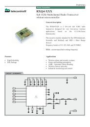
Antenna Design<br />
The design and positioning of the aerial is as crucial as the module performance itself in achieving a good<br />
wireless system range. The following will assist the designer in maximising system performance.<br />
The RF ground pin should be connected to a ground plane which should shield the aerial connection and the<br />
PCB layout around the aerial track itself should be such as to give a 50 Ohm impedance. The aerial should be<br />
kept as far away from sources of electrical interference as physically possible. The specified power supply<br />
decoupling capacitors should be placed close to the module as possible and have direct connections to the<br />
relevant pins.<br />
The antenna ‘hot end’ should be kept clear of any objects, especially any metal as this can severely restrict the<br />
efficiency of the antenna to receive power. Earth planes restricting the radiation path of the antenna will also<br />
have the same effect.<br />
The best range will be achieved with either a straight piece of wire, rod or PCB track @ ¼ wavelength (15.5cm<br />
@ 433.9MHz). Increased range may be achieved if this ¼ wave antenna is placed perpendicular to and in the<br />
middle of a solid earth plane measuring at least 16cm radius. In this case, the antenna should be connected<br />
to the module using 50 Ohm coaxial cable and the PCB track layout tips given above should be observed.<br />
Helical Antenna<br />
Whip Antenna<br />
RF<br />
RF<br />
34mm @ 433MHz<br />
15.5cm @ 433MHz<br />
17 turns equally spaced<br />
= 5mm (inside)<br />
telecontrolli srl web site: www.telecontrolli.com page 6