Holtek HT658/S Data Sheet - Simple Solutions
Holtek HT658/S Data Sheet - Simple Solutions
Holtek HT658/S Data Sheet - Simple Solutions

You also want an ePaper? Increase the reach of your titles
YUMPU automatically turns print PDFs into web optimized ePapers that Google loves.
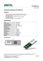
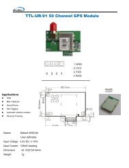
<strong>Holtek</strong> <strong>HT658</strong>/S <strong>Data</strong> <strong>Sheet</strong><br />
FEATURES<br />
WIRELESS MADE SIMPLE<br />
• Operating voltage: 2.4V~12V<br />
• Low power and high noise immunity CMOS<br />
technology<br />
• Low standby current<br />
• Capable of decoding 18 bits of information<br />
• Pairs with HOLTEK’s HT640 encoder<br />
• 10 address pins<br />
• 8 data pins<br />
• Trinary address setting<br />
• Two times of receiving check<br />
• Built-in oscillator needs only a 5% resistor<br />
• Valid transmission indictor<br />
• Easily interface with an RF or an infrared<br />
transmission medium<br />
• Minimal external components<br />
APPLICATIONS<br />
• Burglar alarm system<br />
• Smoke and fire alarm system<br />
• Garage door controllers<br />
• Car door controllers<br />
• Car alarm system<br />
• Security system<br />
• Cordless telephones<br />
• Other remote control systems<br />
GENERAL DESCRIPTION<br />
The <strong>HT658</strong>/S decoder is a CMOS LSI for remote control system applications. It is paired with the<br />
HT640/S encoder. The <strong>HT658</strong> decoder receives serial address and data from the encoder that are<br />
transmitted by a carrier using an RF or an IR transmission medium. It then compares the serial input<br />
data twice continuously with its local address. If no errors or unmatched codes are encountered, the<br />
input data codes are decoded and then transferred to the output pins. The VT pin also goes high to<br />
indicate a valid transmission. The decoder is capable of decoding 18 bits of information that consists<br />
of 10 bits of address and 8 bits of data.<br />
Note:<br />
This product is manufactured and supported by <strong>Holtek</strong> Semiconductor. This data sheet is provided as a courtesy to Linx customers<br />
and is believed to be accurate at the time of publication, however these specifications may change at any time without notice. Linx<br />
Technologies makes no representation as to the accuracy or suitability of this information for any purpose. For more information<br />
please contact <strong>Holtek</strong> at www.holtek.com.
<strong>Holtek</strong> <strong>HT658</strong>/S <strong>Data</strong> <strong>Sheet</strong> Page 2<br />
PIN OUT<br />
D1<br />
D2<br />
D3<br />
D4<br />
D5<br />
D6<br />
D7<br />
VT<br />
DIN<br />
OSC2<br />
OSC1<br />
VSS<br />
1<br />
2<br />
3<br />
4<br />
5<br />
6<br />
7<br />
8<br />
9<br />
10<br />
11<br />
12<br />
24<br />
23<br />
22<br />
21<br />
20<br />
19<br />
18<br />
17<br />
16<br />
15<br />
14<br />
13<br />
VDD<br />
D0<br />
A9<br />
A8<br />
A7<br />
A6<br />
A5<br />
A4<br />
A3<br />
A2<br />
A1<br />
A0<br />
PIN DESCRIPTIONS<br />
Pin Name<br />
A0-A17<br />
I/O<br />
I<br />
Internal<br />
Connection<br />
TRANSMISSION<br />
GATE<br />
Description<br />
Input pins for address A0-A17 setting<br />
They can be externally set to VDD, VSS or left open.<br />
D10-D17 O CMOS OUT Output data pins<br />
DIN I CMOS IN Serial data input pin<br />
VT O CMOS OUT Valid transmission, active high<br />
OSC1 I OSCILLATOR Oscillator input pin<br />
OSC2 O OSCILLATOR Oscillator output pin<br />
VSS I — Negative power supply (GND)<br />
VDD I — Positive power supply<br />
APPROXIMATE INTERNAL CIRCUITS<br />
TRANSMISSION<br />
GATE<br />
CMOS OUT CMOS IN OSCILLATOR<br />
EN<br />
OSC1<br />
OSC2
<strong>Holtek</strong> <strong>HT658</strong>/S <strong>Data</strong> <strong>Sheet</strong> Page 3<br />
ABSOLUTE MAXIMUM RATINGS*<br />
Supply Voltage .............. –0.3V to 13V Storage Temperature................. –50°C to 125°C<br />
Input Voltage..................VSS–0.3V to VDD+0.3V Operating Temperature............... –20°C to 75°C<br />
*Note: Stresses above those listed under “Absolute Maximum Ratings” may cause permanent damage to the<br />
device. These are stress ratings only. Functional operation of this device at these or any other conditions<br />
above those indicated in the operational sections of this specification is not implied and exposure to absolute<br />
maximum rating conditions for extened periods may affect device reliability.<br />
ELECTRICAL CHARACTERISTICS<br />
Symbol<br />
V DD<br />
V DD Operating Voltage — — 3 — 12 V<br />
I STB<br />
Standby Current<br />
I DD Operating Current 5V<br />
I O<br />
I VT<br />
Parameter<br />
<strong>Data</strong> Output Source Current<br />
(D10-D17)<br />
<strong>Data</strong> Output Sink Current<br />
(D10-D17)<br />
5V<br />
Oscillator Stops<br />
— 0.1 1 µA<br />
12V — 2 4 µA<br />
5V<br />
Test Conditions<br />
Conditions<br />
No Load<br />
F OSC = 100kHz<br />
— 0.2 1 mA<br />
V OH= 4.5V –0.5 –1 — mA<br />
V OL= 0.5V 0.5 1 — mA<br />
VT Output Source Current<br />
V OH = 4.5V –2 –4 — mA<br />
5V<br />
VT Output Sink Current V OL = 0.5V 1 2 — mA<br />
V IH "H" Input Voltage 5V — 3.5 — 5 V<br />
V IL "L" Input Voltage 5V — 0 — 1 V<br />
F OSC Oscillator Frequency 10V R OSC = 330kΩ<br />
DECODER OSCILLATOR FREQUENCY VS SUPPLY VOLTAGE<br />
Min. Typ. Max. Unit<br />
— 100 — kHz<br />
300<br />
275<br />
250<br />
120k<br />
225<br />
200<br />
150k<br />
Fosc (kHz)<br />
175<br />
150<br />
125<br />
180k<br />
220k<br />
270k<br />
Rosc (ohms)<br />
100<br />
75<br />
50<br />
25<br />
330k<br />
390k<br />
470k<br />
560k<br />
680k<br />
820k<br />
1M<br />
1.5M<br />
2M<br />
2 3 4 5 6 7 8 9 10 11 12 12.5<br />
VDD (VDC)
<strong>Holtek</strong> <strong>HT658</strong>/S <strong>Data</strong> <strong>Sheet</strong> Page 4<br />
FUNCTIONAL DESCRIPTION<br />
The <strong>HT658</strong> decoder provides ten address and 8<br />
data pins in a 24 pin SOP package. It is paired<br />
with the HT640 encoder. The decoders receive<br />
data transmitted by the encoders and interpret<br />
the first 10 bits of the code period as address and<br />
the last 8 bits as data. A signal on the DIN pin<br />
then activates the oscillator, which in turns<br />
decodes the incoming address and data. The<br />
decoders will check the received address twice<br />
continuously. If all the received address codes<br />
match the contents of the decoder’s local<br />
address, the 8 bits of data are decoded to activate<br />
the output pins, and the VT pin is set high to<br />
indicate a valid transmission. That will last until<br />
the address code is incorrect or no signal has<br />
been received. The output of the VT pin is high<br />
only when the transmission is valid. Otherwise it<br />
is low always. The output type is momentary. The<br />
data outputs follow the encoder during a valid<br />
transmission and then reset.<br />
Note: The oscillator is disabled in the standby<br />
state and activated as long as a logic “high” signal<br />
is applied to the DIN pin. i.e., the DIN should<br />
be kept “low” if there is no signal input.<br />
No<br />
No<br />
Power On<br />
Standby Mode<br />
Code In?<br />
Yes<br />
Address Bits<br />
Matched?<br />
Yes<br />
Store <strong>Data</strong><br />
Match<br />
Previous Stored<br />
<strong>Data</strong>?<br />
Yes<br />
2 Times<br />
of Checking<br />
Completed?<br />
Yes<br />
<strong>Data</strong> to Output &<br />
Activate VT<br />
No<br />
No<br />
Disable VT &<br />
Ignore the Rest of<br />
This Word<br />
No<br />
Address or<br />
<strong>Data</strong> Error?<br />
Yes<br />
BLOCK DIAGRAM<br />
OSC2<br />
OSC1<br />
Oscillator<br />
Divider<br />
<strong>Data</strong> Shift<br />
Register<br />
<strong>Data</strong><br />
DIN<br />
Buffer<br />
<strong>Data</strong> Detector<br />
Sync. Detector Comparator Comparator Control Logic<br />
Transmission Gate Circuit<br />
Buffer<br />
VT<br />
Address<br />
VDD<br />
VSS
<strong>Holtek</strong> <strong>HT658</strong>/S <strong>Data</strong> <strong>Sheet</strong> Page 5<br />
ENCODER/DECODER TIMING<br />
Encoder<br />
Transmit<br />
Enable<br />
Encoder<br />
<strong>Data</strong> Out<br />
Decoder VT<br />
Decoder<br />
<strong>Data</strong> Out<br />
< 1 Word<br />
3 Words<br />
2 Words<br />
Check<br />
Transmitted Continuously 3 Words<br />
2 14 Clocks 2 14 Clocks<br />
Check<br />
1/2 Clock Time<br />
1/2 Clock Time<br />
ENCODER/DECODER DATA STRUCTURE<br />
SYNC BITS<br />
ADDRESS BITS<br />
DATA BITS<br />
A&D BITS<br />
PULLED TO<br />
VCC<br />
A&D BITS<br />
OPEN<br />
A&D Bits<br />
PULLED TO<br />
GND<br />
SYNC<br />
PERIOD<br />
SYNC BITS A0 A1 A2 A3 A4 A5 A6 A7 A8 A9 D0 D1 D2 D3 D4 D5 D6 D7<br />
15.1mS 5.6mS 26mS 21mS<br />
TIME DEPENDANT ON OSCILLATOR RESISTOR CHOSEN (390k)<br />
22.30%<br />
8.27%<br />
38.40%<br />
31.02%<br />
PERCENTAGES OF TOTAL TIME FOR ONE WORD PLUS SYNC<br />
Bit Pattern Interpretation<br />
fosc/33<br />
"One"<br />
"Zero"<br />
"Open"
<strong>Holtek</strong> <strong>HT658</strong>/S <strong>Data</strong> <strong>Sheet</strong> Page 6<br />
SOP-24 PACKAGE DIMENSIONS<br />
0.419<br />
(10.643)<br />
0.300<br />
(7.620)<br />
0.020<br />
(0.508)<br />
0.038<br />
(0.965)<br />
0.012<br />
(0.305)<br />
10˚<br />
0.104<br />
(2.642)<br />
0.050 typ.<br />
(1.27)<br />
0.614<br />
(15.596)<br />
0.004 min.<br />
(0.102)<br />
APPLICATION CIRCUIT<br />
ANTENNA<br />
VCC<br />
1uF<br />
VCC<br />
GND<br />
GND<br />
1<br />
NC<br />
2<br />
NC<br />
3<br />
NC<br />
4<br />
GND<br />
5<br />
VCC<br />
6<br />
PDN<br />
7<br />
RSSI<br />
8<br />
DATA<br />
RXM-xxx-LR-S<br />
ANT 16<br />
GND 15<br />
NC 14<br />
NC 13<br />
NC 12<br />
NC 11<br />
NC 10<br />
NC 9<br />
GND<br />
390k<br />
1<br />
D1<br />
2<br />
3<br />
D3<br />
D4<br />
D5<br />
6<br />
7<br />
8<br />
VT<br />
DIN<br />
OSC1<br />
11<br />
OSC2<br />
12<br />
GND<br />
HT_658/S<br />
VCC 24<br />
D0 23<br />
A9 22<br />
A8 21<br />
A7 20<br />
A6 19<br />
A5 18<br />
A4 17<br />
A3 16<br />
A2 15<br />
A1 14<br />
A0 13<br />
GND<br />
GND