RA30H4047M - RFPhone
RA30H4047M - RFPhone
RA30H4047M - RFPhone

You also want an ePaper? Increase the reach of your titles
YUMPU automatically turns print PDFs into web optimized ePapers that Google loves.
ELECTROSTATIC SENSITIVE DEVICE<br />
OBSERVE HANDLING PRECAUTIONS<br />
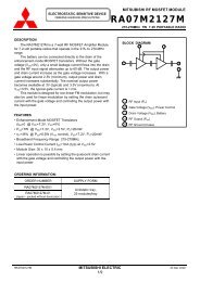
MITSUBISHI RF POWER MODULE<br />
<strong>RA30H4047M</strong><br />
PRECAUTIONS, RECOMMENDATIONS, and APPLICATION INFORMATION:<br />
Construction:<br />
This module consists of an alumina substrate soldered onto a copper flange. For mechanical protection, a plastic cap<br />
is attached with silicone. The MOSFET transistor chips are die bonded onto metal, wire bonded to the substrate, and<br />
coated with resin. Lines on the substrate (eventually inductors), chip capacitors, and resistors form the bias and<br />
matching circuits. Wire leads soldered onto the alumina substrate provide the DC and RF connection.<br />
Following conditions must be avoided:<br />
a) Bending forces on the alumina substrate (for example, by driving screws or from fast thermal changes)<br />
b) Mechanical stress on the wire leads (for example, by first soldering then driving screws or by thermal expansion)<br />
c) Defluxing solvents reacting with the resin coating on the MOSFET chips (for example, Trichlorethylene)<br />
d) Frequent on/off switching that causes thermal expansion of the resin<br />
e) ESD, surge, overvoltage in combination with load VSWR, and oscillation<br />
ESD:<br />
This MOSFET module is sensitive to ESD voltages down to 1000V. Appropriate ESD precautions are required.<br />
Mounting:<br />
Heat sink flatness must be less than 50 µm (a heat sink that is not flat or particles between module and heat sink may<br />
cause the ceramic substrate in the module to crack by bending forces, either immediately when driving screws or later<br />
when thermal expansion forces are added).<br />
A thermal compound between module and heat sink is recommended for low thermal contact resistance and to reduce<br />
the bending stress on the ceramic substrate caused by the temperature difference to the heat sink.<br />
The module must first be screwed to the heat sink, then the leads can be soldered to the printed circuit board.<br />
M3 screws are recommended with a tightening torque of 0.4 to 0.6 Nm.<br />
Soldering and Defluxing:<br />
This module is designed for manual soldering.<br />
The leads must be soldered after the module is screwed onto the heat sink.<br />
The soldering temperature must be lower than 260°C for a maximum of 10 seconds, or lower than 350°C for a maximum<br />
of three seconds.<br />
Ethyl Alcohol is recommend for removing flux. Trichlorethylene solvents must not be used (they may cause bubbles in<br />
the coating of the transistor chips which can lift off the bond wires).<br />
Thermal Design of the Heat Sink:<br />
At P out =30W, V DD =12.5V and P in =50mW each stage transistor operating conditions are:<br />
Stage<br />
P in<br />
(W)<br />
P out<br />
(W)<br />
R th(ch-case)<br />
(°C/W)<br />
I DD @ η T =40%<br />
(A)<br />
1 st 0.05 1.5 5.0 0.30<br />
2 nd 1.5 9.0 2.4 1.50<br />
3 rd 9.0 30.0 1.2 4.20<br />
The channel temperatures of each stage transistor T ch = T case + (V DD x I DD - P out + P in ) x R th(ch-case) are:<br />
V DD<br />
(V)<br />
12.5<br />
T ch1 = T case + (12.5V x 0.30A – 1.5W + 0.05W) x 5.0°C/W = T case + 11.5 °C<br />
T ch2 = T case + (12.5V x 1.50A - 9.0W + 1.5W) x 2.4°C/W = T case + 27.0 °C<br />
T ch3 = T case + (12.5V x 4.20A - 30.0W + 9.0W) x 1.2°C/W = T case + 37.8 °C<br />
For long-term reliability, it is best to keep the module case temperature (T case ) below 90°C. For an ambient<br />
temperature T air =60°C and P out =30W, the required thermal resistance R th (case-air) = ( T case - T air ) / ( (P out / η T ) - P out +<br />
P in ) of the heat sink, including the contact resistance, is:<br />
R th(case-air) = (90°C - 60°C) / (30W/40% – 30W + 0.05W) = 0.67 °C/W<br />
When mounting the module with the thermal resistance of 0.67 °C/W, the channel temperature of each stage transistor<br />
is:<br />
T ch1 = T air + 41.5 °C<br />
T ch2 = T air + 57.0 °C<br />
T ch3 = T air + 67.8 °C<br />
The 175°C maximum rating for the channel temperature ensures application under derated conditions.<br />
<strong>RA30H4047M</strong> MITSUBISHI ELECTRIC 23 Dec 2002<br />
7/9