RA30H4047M - RFPhone
RA30H4047M - RFPhone
RA30H4047M - RFPhone

Create successful ePaper yourself
Turn your PDF publications into a flip-book with our unique Google optimized e-Paper software.
ELECTROSTATIC SENSITIVE DEVICE<br />
OBSERVE HANDLING PRECAUTIONS<br />
MITSUBISHI RF MOSFET MODULE<br />
<strong>RA30H4047M</strong><br />
400-470MHz 30W 12.5V MOBILE RADIO<br />
DESCRIPTION<br />
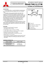
The <strong>RA30H4047M</strong> is a 30-watt RF MOSFET Amplifier<br />
Module for 12.5-volt mobile radios that operate in the 400- to<br />
470-MHz range.<br />
The battery can be connected directly to the drain of the<br />
enhancement-mode MOSFET transistors. Without the gate<br />
voltage (V GG =0V), only a small leakage current flows into the<br />
drain and the RF input signal attenuates up to 60 dB. The output<br />
power and drain current increase as the gate voltage increases.<br />
With a gate voltage around 4V (minimum), output power and<br />
drain current increases substantially. The nominal output power<br />
becomes available at 4.5V (typical) and 5V (maximum). At<br />
V GG =5V, the typical gate current is 1 mA.<br />
This module is designed for non-linear FM modulation, but may<br />
also be used for linear modulation by setting the drain quiescent<br />
current with the gate voltage and controlling the output power with<br />
the input power.<br />
FEATURES<br />
• Enhancemen- Mode MOSFET Transistors<br />
(I DD ≅0 @ V DD =12.5V, V GG =0V)<br />
• P out >30W, η T >40% @ V DD =12.5V, V GG =5V, P in =50mW<br />
• Broadband Frequency Range: 400-470MHz<br />
• Low-Power Control Current I GG =1mA (typ) at V GG =5V<br />
• Module Size: 66 x 21 x 9.88 mm<br />
• Linear operation is possible by setting the quiescent drain<br />
current with the gate voltage and controlling the output power<br />
with the input power<br />
BLOCK DIAGRAM<br />
2<br />
3<br />
1<br />
1 RF Input (P in)<br />
2 Gate Voltage (V GG), Power Control<br />
3 Drain Voltage (V DD), Battery<br />
4 RF Output (P out)<br />
5 RF Ground (Case)<br />
4<br />
5<br />
ORDERING INFORMATION:<br />
ORDER NUMBER<br />
<strong>RA30H4047M</strong>-E01<br />
<strong>RA30H4047M</strong>-01<br />
(Japan - packed without desiccator)<br />
SUPPLY FORM<br />
Antistatic tray,<br />
10 modules/tray<br />
<strong>RA30H4047M</strong> MITSUBISHI ELECTRIC 23 Dec 2002<br />
1/9
ELECTROSTATIC SENSITIVE DEVICE<br />
OBSERVE HANDLING PRECAUTIONS<br />
MAXIMUM RATINGS (T case =+25°C, unless otherwise specified)<br />
MITSUBISHI RF POWER MODULE<br />
<strong>RA30H4047M</strong><br />
SYMBOL PARAMETER CONDITIONS RATING UNIT<br />
V DD Drain Voltage V GG
ELECTROSTATIC SENSITIVE DEVICE<br />
OBSERVE HANDLING PRECAUTIONS<br />
MITSUBISHI RF POWER MODULE<br />
<strong>RA30H4047M</strong><br />
TYPICAL PERFORMANCE (T case =+25°C, Z G =Z L =50Ω, unless otherwise specified)<br />
TYPICAL PERFORMANCE DATA<br />
OUTPUT POWER Po(W)<br />
OUTPUT POWER, TOTAL EFFICIENCY,<br />
INPUT VSWR VS. FREQUENCY<br />
60<br />
50<br />
40<br />
30<br />
20<br />
Eta<br />
Po<br />
@V<br />
VDD=12.5V, Pin=50mW<br />
VGG=5V, ZG=ZL=50ohm,<br />
Tc=+25deg.C<br />
120<br />
100<br />
80<br />
60<br />
40<br />
TOTAL EFFICIENCY<br />
Eta(%)<br />
OUTPUT POWER<br />
Po(dBm)<br />
OUTPUT POWER, EFFICIENCY<br />
VS. INPUT POWER<br />
50<br />
10<br />
ρin 20<br />
30<br />
0<br />
0<br />
0<br />
-10 -5 0 5 10 15 20<br />
390 400 410 420 430 440 450 460 470 480<br />
INPUT POWER Pin(dBm)<br />
FREQUENCY f(MHz)<br />
45<br />
40<br />
35<br />
Po<br />
Eta<br />
freq.=400MHz<br />
Gp<br />
VDD=12.5V , VGG=5V<br />
ZG=ZL=50ohm, Tc=+25deg.C<br />
100<br />
80<br />
60<br />
40<br />
20<br />
TOTAL EFFICIENCY<br />
Eta(%)<br />
OUTPUT POWER<br />
Po(dBm)<br />
OUTPUT POWER, EFFICIENCY<br />
VS. INPUT POWER<br />
50<br />
45<br />
40<br />
35<br />
30<br />
0<br />
-10 -5 0 5 10 15 20<br />
Po<br />
INPUT POWER Pin(dBm)<br />
Eta<br />
freq.=435MHz<br />
VDD=12.5V , VGG=5V<br />
ZG=ZL=50ohm, Tc=+25deg.C<br />
Gp<br />
100<br />
80<br />
60<br />
40<br />
20<br />
TOTAL EFFICIENCY<br />
Eta(%)<br />
OUTPUT POWER<br />
Po(dBm)<br />
OUTPUT POWER, EFFICIENCY<br />
VS. INPUT POWER<br />
50<br />
45<br />
40<br />
35<br />
Po<br />
Eta<br />
freq.=470MHz<br />
VDD=12.5V , VGG=5V<br />
ZG=ZL=50ohm, Tc=+25deg.C<br />
30<br />
0<br />
-10 -5 0 5 10 15 20<br />
INPUT POWER Pin(dBm)<br />
Gp<br />
100<br />
80<br />
60<br />
40<br />
20<br />
TOTAL EFFICIENCY<br />
Eta(%)<br />
OUTPUT POWER Po(W)<br />
OUTPUT POWER, EFFICIENCY<br />
VS. DRAIN SUPPLY VOLTAGE<br />
70<br />
60<br />
50<br />
40<br />
30<br />
20<br />
10<br />
0<br />
f=400/435/470MHz<br />
VGG=5V, Pin=50mW<br />
ZG=ZL=50ohm, Tc=+25deg.C<br />
Eta<br />
Po<br />
: 400MHz<br />
: 435MHz<br />
- - - - -:470MHz<br />
0 2 4 6 8 10 12 14 16 18<br />
DRAIN SUPPLY VOLTAGE (VDD)<br />
140<br />
120<br />
100<br />
80<br />
60<br />
40<br />
20<br />
0<br />
TOTAL EFFICIENCY<br />
Eta(%)<br />
OUTPUT POWER Po(W)<br />
60<br />
50<br />
40<br />
30<br />
20<br />
10<br />
OUTPUT POWER, EFFICIENCY<br />
VS. GATE SUPPLY VOLTAGE<br />
0<br />
f=400MHz<br />
VDD=12.5V, Pin=50mW<br />
ZG=ZL=50ohm, Tv=+25degC<br />
Eta<br />
Po<br />
2 2.5 3 3.5 4 4.5 5 5.5 6<br />
GATE SUPPLY VOLTAGE (VGG)<br />
120<br />
100<br />
80<br />
60<br />
40<br />
20<br />
0<br />
TOTL EFFICIENCY<br />
Eta(%)<br />
OUTPUT POWER Po(W)<br />
OUTPUT POWER, EFFICIENCY<br />
VS. GATE SUPPLY VOLTAGE<br />
60<br />
50<br />
40<br />
30<br />
20<br />
10<br />
f=435MHz<br />
VDD=12.5V, Pin=50mW<br />
ZG=ZL=50ohm, Tc=+25deg.C<br />
0<br />
0<br />
2 2.5 3 3.5 4 4.5 5 5.5 6<br />
Po<br />
Eta<br />
GATE SUPPLY VOLTAGE (VGG)<br />
120<br />
100<br />
80<br />
60<br />
40<br />
20<br />
TOTAL EFFICIENCY<br />
Eta(%)<br />
OUTPUT POWER Po(W)<br />
OUTPUT POWER, EFFICIENCY<br />
VS. GATE SUPPLY VOLTAGE<br />
60<br />
50<br />
40<br />
30<br />
20<br />
10<br />
RA 30H4047M MITSUBISHI ELECTRIC 23 Dec 2002<br />
3/9<br />
0<br />
f=470MHz<br />
VDD=12.5V, Pin=50mW<br />
ZG=ZL=50ohm, Tc=+25deg.C<br />
Po<br />
Eta<br />
2 2.5 3 3.5 4 4.5 5 5.5 6<br />
GATE SUPPLY VOLTAGE (VGG)<br />
120<br />
100<br />
80<br />
60<br />
40<br />
20<br />
0<br />
TOTAL EFFICIENCY<br />
Eta(%)
ELECTROSTATIC SENSITIVE DEVICE<br />
OBSERVE HANDLING PRECAUTIONS<br />
MITSUBISHI RF POWER MODULE<br />
<strong>RA30H4047M</strong><br />
TYPICAL PERFORMANCE (T case =+25°C, Z G =Z L =50Ω, unless otherwise specified)<br />
Now Preparing<br />
<strong>RA30H4047M</strong> MITSUBISHI ELECTRIC 23 Dec 2002<br />
4/9
ELECTROSTATIC SENSITIVE DEVICE<br />
OBSERVE HANDLING PRECAUTIONS<br />
MITSUBISHI RF POWER MODULE<br />
<strong>RA30H4047M</strong><br />
OUTLINE DRAWING (mm)<br />
66.0 ±0.5<br />
3.0 ±0.3<br />
7.25 ±0.8<br />
60.0 ±0.5<br />
51.5 ±0.5<br />
2-R2 ±0.5<br />
14.0 ±1 21.0 ±0.5<br />
9.5 ±0.5<br />
2.0 ±0.5<br />
1 2 3 4<br />
5<br />
4.0 ±0.3<br />
Ø0.45 ±0.15<br />
17.0 ±0.5<br />
12.0 ±1<br />
16.5 ±1<br />
43.5 ±1<br />
55.5 ±1<br />
3.1 +0.6/-0.4<br />
0.09 ±0.02<br />
7.5 ±0.5<br />
2.3 ±0.3<br />
(9.88)<br />
(50.4)<br />
1 RF Input (P in )<br />
2 Gate Voltage (V GG )<br />
3 Drain Voltage (V DD )<br />
4 RF Output (P out )<br />
5 RF Ground (Case)<br />
<strong>RA30H4047M</strong> MITSUBISHI ELECTRIC 23 Dec 2002<br />
5/9
ELECTROSTATIC SENSITIVE DEVICE<br />
OBSERVE HANDLING PRECAUTIONS<br />
MITSUBISHI RF POWER MODULE<br />
<strong>RA30H4047M</strong><br />
TEST BLOCK DIAGRAM<br />
Power<br />
Meter<br />
DUT<br />
5<br />
Spectrum<br />
Analyzer<br />
1<br />
2<br />
3<br />
4<br />
Signal<br />
Generator<br />
Attenuator<br />
Preamplifier<br />
Attenuator<br />
Directional<br />
Coupler<br />
Z G =50Ω Z L =50Ω<br />
Directional<br />
Coupler<br />
Attenuator<br />
Power<br />
Meter<br />
C1<br />
C2<br />
- +<br />
DC Power<br />
Supply V GG<br />
+ -<br />
DC Power<br />
Supply V DD<br />
C1, C2: 4700pF, 22uF in parallel<br />
1 RF Input (P in )<br />
2 Gate Voltage (V GG )<br />
3 Drain Voltage (V DD )<br />
4 RF Output (P out )<br />
5 RF Ground (Case)<br />
EQUIVALENT CIRCUIT<br />
2 3<br />
1<br />
4<br />
5<br />
<strong>RA30H4047M</strong> MITSUBISHI ELECTRIC 23 Dec 2002<br />
6/9
ELECTROSTATIC SENSITIVE DEVICE<br />
OBSERVE HANDLING PRECAUTIONS<br />
MITSUBISHI RF POWER MODULE<br />
<strong>RA30H4047M</strong><br />
PRECAUTIONS, RECOMMENDATIONS, and APPLICATION INFORMATION:<br />
Construction:<br />
This module consists of an alumina substrate soldered onto a copper flange. For mechanical protection, a plastic cap<br />
is attached with silicone. The MOSFET transistor chips are die bonded onto metal, wire bonded to the substrate, and<br />
coated with resin. Lines on the substrate (eventually inductors), chip capacitors, and resistors form the bias and<br />
matching circuits. Wire leads soldered onto the alumina substrate provide the DC and RF connection.<br />
Following conditions must be avoided:<br />
a) Bending forces on the alumina substrate (for example, by driving screws or from fast thermal changes)<br />
b) Mechanical stress on the wire leads (for example, by first soldering then driving screws or by thermal expansion)<br />
c) Defluxing solvents reacting with the resin coating on the MOSFET chips (for example, Trichlorethylene)<br />
d) Frequent on/off switching that causes thermal expansion of the resin<br />
e) ESD, surge, overvoltage in combination with load VSWR, and oscillation<br />
ESD:<br />
This MOSFET module is sensitive to ESD voltages down to 1000V. Appropriate ESD precautions are required.<br />
Mounting:<br />
Heat sink flatness must be less than 50 µm (a heat sink that is not flat or particles between module and heat sink may<br />
cause the ceramic substrate in the module to crack by bending forces, either immediately when driving screws or later<br />
when thermal expansion forces are added).<br />
A thermal compound between module and heat sink is recommended for low thermal contact resistance and to reduce<br />
the bending stress on the ceramic substrate caused by the temperature difference to the heat sink.<br />
The module must first be screwed to the heat sink, then the leads can be soldered to the printed circuit board.<br />
M3 screws are recommended with a tightening torque of 0.4 to 0.6 Nm.<br />
Soldering and Defluxing:<br />
This module is designed for manual soldering.<br />
The leads must be soldered after the module is screwed onto the heat sink.<br />
The soldering temperature must be lower than 260°C for a maximum of 10 seconds, or lower than 350°C for a maximum<br />
of three seconds.<br />
Ethyl Alcohol is recommend for removing flux. Trichlorethylene solvents must not be used (they may cause bubbles in<br />
the coating of the transistor chips which can lift off the bond wires).<br />
Thermal Design of the Heat Sink:<br />
At P out =30W, V DD =12.5V and P in =50mW each stage transistor operating conditions are:<br />
Stage<br />
P in<br />
(W)<br />
P out<br />
(W)<br />
R th(ch-case)<br />
(°C/W)<br />
I DD @ η T =40%<br />
(A)<br />
1 st 0.05 1.5 5.0 0.30<br />
2 nd 1.5 9.0 2.4 1.50<br />
3 rd 9.0 30.0 1.2 4.20<br />
The channel temperatures of each stage transistor T ch = T case + (V DD x I DD - P out + P in ) x R th(ch-case) are:<br />
V DD<br />
(V)<br />
12.5<br />
T ch1 = T case + (12.5V x 0.30A – 1.5W + 0.05W) x 5.0°C/W = T case + 11.5 °C<br />
T ch2 = T case + (12.5V x 1.50A - 9.0W + 1.5W) x 2.4°C/W = T case + 27.0 °C<br />
T ch3 = T case + (12.5V x 4.20A - 30.0W + 9.0W) x 1.2°C/W = T case + 37.8 °C<br />
For long-term reliability, it is best to keep the module case temperature (T case ) below 90°C. For an ambient<br />
temperature T air =60°C and P out =30W, the required thermal resistance R th (case-air) = ( T case - T air ) / ( (P out / η T ) - P out +<br />
P in ) of the heat sink, including the contact resistance, is:<br />
R th(case-air) = (90°C - 60°C) / (30W/40% – 30W + 0.05W) = 0.67 °C/W<br />
When mounting the module with the thermal resistance of 0.67 °C/W, the channel temperature of each stage transistor<br />
is:<br />
T ch1 = T air + 41.5 °C<br />
T ch2 = T air + 57.0 °C<br />
T ch3 = T air + 67.8 °C<br />
The 175°C maximum rating for the channel temperature ensures application under derated conditions.<br />
<strong>RA30H4047M</strong> MITSUBISHI ELECTRIC 23 Dec 2002<br />
7/9
ELECTROSTATIC SENSITIVE DEVICE<br />
OBSERVE HANDLING PRECAUTIONS<br />
MITSUBISHI RF POWER MODULE<br />
<strong>RA30H4047M</strong><br />
Output Power Control:<br />
Depending on linearity, the following two methods are recommended to control the output power:<br />
a) Non-linear FM modulation:<br />
By the gate voltage (V GG ).<br />
When the gate voltage is close to zero, the RF input signal is attenuated up to 60 dB and only a small leakage<br />
current flows from the battery into the drain.<br />
Around V GG =4V, the output power and drain current increases substantially.<br />
Around V GG =4.5V (typical) to V GG =5V (maximum), the nominal output power becomes available.<br />
b) Linear AM modulation:<br />
By RF input power P in .<br />
The gate voltage is used to set the drain’s quiescent current for the required linearity.<br />
Oscillation:<br />
To test RF characteristics, this module is put on a fixture with two bias decoupling capacitors each on gate and drain,<br />
a 4.700 pF chip capacitor, located close to the module, and a 22 µF (or more) electrolytic capacitor.<br />
When an amplifier circuit around this module shows oscillation, the following may be checked:<br />
a) Do the bias decoupling capacitors have a low inductance pass to the case of the module?<br />
b) Is the load impedance Z L =50Ω?<br />
c) Is the source impedance Z G =50Ω?<br />
Frequent on/off switching:<br />
In base stations, frequent on/off switching can cause thermal expansion of the resin that coats the transistor chips and<br />
can result in reduced or no output power. The bond wires in the resin will break after long-term thermally induced<br />
mechanical stress.<br />
Quality:<br />
Mitsubishi Electric is not liable for failures resulting from base station operation time or operating conditions exceeding<br />
those of mobile radios.<br />
This module technology results from more than 20 years of experience, field proven in tens of millions of mobile radios.<br />
Currently, most returned modules show failures such as ESD, substrate crack, and transistor burnout, which are<br />
caused by improper handling or exceeding recommended operating conditions. Few degradation failures are found.<br />
Keep safety first in your circuit designs!<br />
Mitsubishi Electric Corporation puts the maximum effort into making semiconductor products better and more reliable, but<br />
there is always the possibility that trouble may occur. Trouble with semiconductors may lead to personal injury, fire or property<br />
damage. Remember to give due consideration to safety when making your circuit designs, with appropriate measures such<br />
as (i) placement of substitutive, auxiliary circuits, (ii) use of non-flammable material, or (iii) prevention against any<br />
malfunction or mishap.<br />
<strong>RA30H4047M</strong> MITSUBISHI ELECTRIC 23 Dec 2002<br />
8/9
SALES CONTACT<br />
JAPAN:<br />
Mitsubishi Electric Corporation<br />
Semiconductor Sales Promotion Department<br />
2-2-3 Marunouchi, Chiyoda-ku<br />
Tokyo, Japan 100<br />
Email: sod.sophp@hq.melco.co.jp<br />
Phone: +81-3-3218-4854<br />
Fax: +81-3-3218-4861<br />
GERMANY:<br />
Mitsubishi Electric Europe B.V.<br />
Semiconductor<br />
Gothaer Strasse 8<br />
D-40880 Ratingen, Germany<br />
Email: semis.info@meg.mee.com<br />
Phone: +49-2102-486-0<br />
Fax: +49-2102-486-3670<br />
HONG KONG:<br />
Mitsubishi Electric Hong Kong Ltd.<br />
Semiconductor Division<br />
41/F. Manulife Tower, 169 Electric Road<br />
North Point, Hong Kong<br />
Email: scdinfo@mehk.com<br />
Phone: +852 2510-0555<br />
Fax: +852 2510-9822<br />
FRANCE:<br />
Mitsubishi Electric Europe B.V.<br />
Semiconductor<br />
25 Boulevard des Bouvets<br />
F-92741 Nanterre Cedex, France<br />
Email: semis.info@meg.mee.com<br />
Phone: +33-1-55685-668<br />
Fax: +33-1-55685-739<br />
SINGAPORE:<br />
Mitsubishi Electric Asia PTE Ltd<br />
Semiconductor Division<br />
307 Alexandra Road<br />
#3-01/02 Mitsubishi Electric Building,<br />
Singapore 159943<br />
Email: semicon@asia.meap.com<br />
Phone: +65 64 732 308<br />
Fax: +65 64 738 984<br />
ITALY:<br />
Mitsubishi Electric Europe B.V.<br />
Semiconductor<br />
Centro Direzionale Colleoni,<br />
Palazzo Perseo 2, Via Paracelso<br />
I-20041 Agrate Brianza, Milano, Italy<br />
Email: semis.info@meg.mee.com<br />
Phone: +39-039-6053-10<br />
Fax: +39-039-6053-212<br />
TAIWAN:<br />
Mitsubishi Electric Taiwan Company, Ltd.,<br />
Semiconductor Department<br />
9F, No. 88, Sec. 6<br />
Chung Shan N. Road<br />
Taipei, Taiwan, R.O.C.<br />
Email: metwnssi@metwn.meap.com<br />
Phone: +886-2-2836-5288<br />
Fax: +886-2-2833-9793<br />
U.K.:<br />
Mitsubishi Electric Europe B.V.<br />
Semiconductor<br />
Travellers Lane, Hatfield<br />
Hertfordshire, AL10 8XB, England<br />
Email: semis.info@meuk.mee.com<br />
Phone: +44-1707-278-900<br />
Fax: +44-1707-278-837<br />
U.S.A.:<br />
Mitsubishi Electric & Electronics USA, Inc.<br />
Electronic Device Group<br />
1050 East Arques Avenue<br />
Sunnyvale, CA 94085<br />
Email: customerservice@edg.mea.com<br />
Phone: 408-730-5900<br />
Fax: 408-737-1129<br />
CANADA:<br />
Mitsubishi Electric Sales Canada, Inc.<br />
4299 14th Avenue<br />
Markham, Ontario, Canada L3R OJ2<br />
Phone: 905-475-7728<br />
Fax: 905-475-1918<br />
AUSTRALIA:<br />
Mitsubishi Electric Australia,<br />
Semiconductor Division<br />
348 Victoria Road<br />
Rydalmere, NSW 2116<br />
Sydney, Australia<br />
Email: semis@meaust.meap.com<br />
Phone: +61 2 9684-7210<br />
+61 2 9684 7212<br />
+61 2 9684 7214<br />
+61 3 9262 9898<br />
Fax: +61 2 9684-7208<br />
+61 2 9684 7245<br />
<strong>RA30H4047M</strong> MITSUBISHI ELECTRIC 23 Dec 2002<br />
9/9