

m15 iso ball valve for control of fluids - sizing sheet - Spirax Sarco
m15 iso ball valve for control of fluids - sizing sheet - Spirax Sarco
m15 iso ball valve for control of fluids - sizing sheet - Spirax Sarco

Create successful ePaper yourself
Turn your PDF publications into a flip-book with our unique Google optimized e-Paper software.
TI-P133-46<br />
ST Issue 1<br />
Cert. No. LRQ 110478<br />
ISO 9001<br />
M15 ISO<br />
Ball Valve <strong>for</strong> Control <strong>of</strong> Fluids<br />
Sizing Sheet<br />
Description<br />
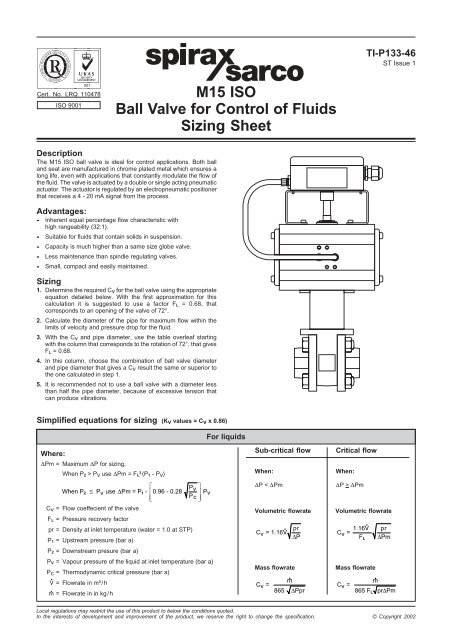
The M15 ISO <strong>ball</strong> <strong>valve</strong> is ideal <strong>for</strong> <strong>control</strong> applications. Both <strong>ball</strong><br />
and seat are manufactured in chrome plated metal which ensures a<br />
long life, even with applications that constantly modulate the flow <strong>of</strong><br />
the fluid. The <strong>valve</strong> is actuated by a double or single acting pneumatic<br />
actuator. The actuator is regulated by an electropneumatic positioner<br />
that receives a 4 - 20 mA signal from the process.<br />
Advantages:<br />
- Inherent equal percentage flow characteristic with<br />
high rangeability (32:1).<br />
- Suitable <strong>for</strong> <strong>fluids</strong> that contain solids in suspension.<br />
- Capacity is much higher than a same size globe <strong>valve</strong>.<br />
- Less maintenance than spindle regulating <strong>valve</strong>s.<br />
- Small, compact and easily maintained.<br />
Sizing<br />
1. Determine the required Cv <strong>for</strong> the <strong>ball</strong> <strong>valve</strong> using the appropriate<br />
equation detailed below. With the first approximation <strong>for</strong> this<br />
calculation it is suggested to use a factor F L = 0.68, that<br />
corresponds to an opening <strong>of</strong> the <strong>valve</strong> <strong>of</strong> 72°.<br />
2. Calculate the diameter <strong>of</strong> the pipe <strong>for</strong> maximum flow within the<br />
limits <strong>of</strong> velocity and pressure drop <strong>for</strong> the fluid.<br />
3. With the Cv and pipe diameter, use the table overleaf starting<br />
with the column that corresponds to the rotation <strong>of</strong> 72°, that gives<br />
F L = 0.68.<br />
4. In this column, choose the combination <strong>of</strong> <strong>ball</strong> <strong>valve</strong> diameter<br />
and pipe diameter that gives a Cv result the same or superior to<br />
the one calculated in step 1.<br />
5. It is recommended not to use a <strong>ball</strong> <strong>valve</strong> with a diameter less<br />
than half the pipe diameter, because <strong>of</strong> excessive tension that<br />
can produce vibrations.<br />
Simplified equations <strong>for</strong> <strong>sizing</strong> (Kv values = Cv x 0.86)<br />
For liquids<br />
Where:<br />
DPm = Maximum DP <strong>for</strong> <strong>sizing</strong>,<br />
When P 2 > Pv use DPm = F L²(P 1 - Pv)<br />
⎡<br />
P v<br />
⎤<br />
When P 2 ≤ P v use DPm = P 1- ⎢0.96 - 0.28 ⎥ Pv<br />
⎢⎣<br />
Pc ⎥⎦<br />
Cv = Flow coeffecient <strong>of</strong> the <strong>valve</strong><br />
F L = Pressure recovery factor<br />
pr = Density at inlet temperature (water = 1.0 at STP)<br />
P 1 = Upstream pressure (bar a)<br />
P 2 = Downstream presure (bar a)<br />
P V = Vapour pressure <strong>of</strong> the liquid at inlet temperature (bar a)<br />
Pc = Thermodynamic critical pressure (bar a)<br />
V = Flowrate in m³/h<br />
m = Flowrate in in kg/h<br />
Sub-critical flow<br />
When:<br />
DP < DPm<br />
Volumetric flowrate<br />
C v = 1.16<br />
Mass flowrate<br />
C = v<br />
<br />
pr<br />
∆P<br />
865 ∆Ppr<br />
Critical flow<br />
When:<br />
DP > DPm<br />
Volumetric flowrate<br />
C = v<br />
Mass flowrate<br />
C = v<br />
1.16 pr<br />
F ∆Pm<br />
L<br />
<br />
865 FL<br />
pr∆Pm<br />
Local regulations may restrict the use <strong>of</strong> this product to below the conditions quoted.<br />
In the interests <strong>of</strong> development and improvement <strong>of</strong> the product, we reserve the right to change the specification. © Copyright 2002
Simplified equations <strong>for</strong> <strong>sizing</strong> (Kv values = Cv x 0.86)<br />
For steam and gases<br />
Where:<br />
Cv = Flow coeffecient <strong>of</strong> the <strong>valve</strong><br />
F L = Pressure recovery factor<br />
pr = Specific density <strong>of</strong> gas (air = 1)<br />
P 1 = Upstream pressure (bar a)<br />
P 2 = Downstream presure (bar a)<br />
T = Inlet temperature in °K (°C + 273)<br />
V = Flowrate <strong>of</strong> gas in Nm³/h (at 15°C and 1 bar a)<br />
m = Flowrate <strong>of</strong> gas in in kg/h<br />
Tso = Superheating <strong>of</strong> steam in °C<br />
(Temperature <strong>of</strong> superheated steam - Temperature<br />
<strong>of</strong> saturated steam)<br />
= Flowrate <strong>of</strong> steam in kg/h<br />
m S<br />
Note: These equations are only a simplified version <strong>of</strong> the<br />
original <strong>sizing</strong> equations <strong>of</strong> the ISA and IEC regulations. The<br />
results are sufficiently close <strong>for</strong> practical use. There could be a<br />
maximum error <strong>of</strong> 8% in the transition <strong>of</strong> non-choked flowrate<br />
to choked flowrate.<br />
Sub-critical flow<br />
When:<br />
DP < 0.5 F L² P 1<br />
For gases<br />
(volumetric flowrate)<br />
C = v<br />
prT<br />
295 P 1² - P2²<br />
For gases<br />
(mass flowrate)<br />
C = v<br />
<br />
T<br />
360 (P 1² - P 2²<br />
)pr<br />
For saturated steam<br />
C = v<br />
s<br />
13.81 P 1² - P2²<br />
For superheated steam<br />
C = v<br />
s<br />
(1 + 0.001 26 T so)<br />
13.81 P 1² - P2²<br />
Critical flow<br />
When:<br />
DP > 0.5 F L² P 1<br />
For gases<br />
(volumetric flowrate)<br />
C = v<br />
prT<br />
257 F L P 1<br />
For gases<br />
(mass flowrate)<br />
C = v<br />
T<br />
311 FLP1<br />
pr<br />
For saturated steam<br />
C = v<br />
s<br />
11.95 F L P 1<br />
For superheated steam<br />
C = v<br />
s<br />
(1 + 0.001 26 T so)<br />
11.95 F L P 1<br />
Cv values <strong>for</strong> reduced bore (RB) <strong>valve</strong>s (Kv values = Cv x 0.86)<br />
Valve Pipe Rotation<br />
size size 0° 9° 18° 27° 36° 45° 54° 63° 72° 81° 90°<br />
½" 0.00 0.00 0.22 0.36 0.58 0.88 1.47 2.17 3.50 5.53 7.00<br />
½" ¾" 0.00 0.00 0.22 0.36 0.58 0.88 1.45 2.12 3.29 4.80 5.66<br />
¾"<br />
1"<br />
1¼"<br />
1½"<br />
2"<br />
2½"<br />
1" 0.00 0.00 0.22 0.36 0.58 0.87 1.44 2.09 3.20 4.53 5.23<br />
¾" 0.00 0.00 0.37 0.62 0.99 1.50 2.52 3.72 6.00 9.48 12.00<br />
1" 0.00 0.00 0.37 0.62 0.99 1.50 2.50 3.69 5.87 8.98 11.03<br />
1¼" 0.00 0.00 0.37 0.62 0.99 1.50 2.49 3.65 5.73 8.52 10.21<br />
1½" 0.00 0.00 0.37 0.62 0.99 1.49 2.48 3.64 5.68 8.35 9.91<br />
1" 0.00 0.00 0.98 1.64 2.61 3.95 6.64 9.80 15.80 24.96 31.60<br />
1¼" 0.00 0.00 0.98 1.64 2.61 3.94 6.59 9.63 15.10 22.45 26.91<br />
1½" 0.00 0.00 0.98 1.64 2.60 3.93 6.55 6.52 14.70 21.20 24.83<br />
2" 0.00 0.00 0.98 1.64 2.60 3.92 6.50 9.36 14.15 19.63 22.41<br />
1¼" 0.00 0.00 1.47 2.46 3.90 5.91 9.93 14.66 23.65 37.37 47.30<br />
1½" 0.00 0.00 1.47 2.46 3.90 5.90 9.88 14.50 23.00 34.95 42.66<br />
2" 0.00 0.00 1.47 2.46 3.89 5.88 9.80 14.24 22.00 31.72 37.14<br />
2½" 0.00 0.00 1.47 2.46 3.89 5.87 9.75 14.09 21.47 30.18 34.74<br />
1½" 0.00 0.00 2.54 4.26 6.77 10.25 17.22 25.42 41.00 64.78 82.00<br />
2" 0.00 0.00 2.54 4.26 6.76 10.21 17.03 24.83 38.65 56.53 66.91<br />
2½" 0.00 0.00 2.54 4.25 6.75 10.18 16.89 24.40 37.08 51.94 59.65<br />
3" 0.00 0.00 2.54 4.25 6.74 10.15 16.75 23.97 35.63 48.16 54.12<br />
1½" 0.00 0.00 3.72 6.24 9.90 15.00 25.20 37.20 60.00 94.80 120.00<br />
2½" 0.00 0.00 3.72 6.24 9.89 14.98 25.10 36.88 58.70 89.92 110.53<br />
3" 0.00 0.00 3.72 6.24 9.88 14.94 24.93 36.33 56.56 82.73 97.93<br />
4" 0.00 0.00 3.72 6.23 9.87 14.90 24.73 35.75 54.43 76.46 87.97<br />
2½" 0.00 0.00 6.08 10.19 16.17 24.50 41.16 60.76 98.00 154.84 196.00<br />
3" 0.00 0.00 6.08 10.19 16.16 24.46 40.99 60.22 95.79 146.53 179.90<br />
4" 0.00 0.00 6.08 10.18 16.14 24.38 40.60 59.01 91.13 131.31 153.72<br />
6" 0.00 0.00 6.08 10.17 16.11 24.28 40.16 57.67 86.43 118.31 133.91<br />
F L - - 0.96 0.94 0.92 0.88 0.82 0.75 0.68 0.62 0.50<br />
M15 ISO Ball Valve <strong>for</strong> Control <strong>of</strong> Fluids - Sizing Sheet TI-P133-46 ST Issue 1


