CM1 系列带剩余电流保护电子可调式断路器 - 常熟开关制造有限公司
CM1 系列带剩余电流保护电子可调式断路器 - 常熟开关制造有限公司
CM1 系列带剩余电流保护电子可调式断路器 - 常熟开关制造有限公司

You also want an ePaper? Increase the reach of your titles
YUMPU automatically turns print PDFs into web optimized ePapers that Google loves.
S<br />
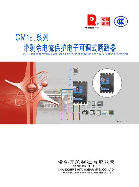
<strong>CM1</strong><br />
EL<br />
系 列<br />
带 剩 余 电 流 保 护 电 子 可 调 式 断 路 器<br />
<strong>CM1</strong><br />
EL<br />
SERIESELECTRONICADJUSTABLEMCCB INCORPORATINGRESIDUALCURRENTPROTECTION<br />
CV 系 列<br />
CW 系 列<br />
CM 系 列<br />
CB 系 列<br />
CK 系 列 CR 系 列 CA 系 列<br />
CJR 系 列 CJD 系 列 CD 系 列 CH 系 列 CE 系 列<br />
2011.12<br />
常 熟 开 关 制 造 有 限 公 司<br />
( 原 常 熟 开 关 厂 )<br />
CHANGSHU SWITCHGEARMFG.CO.,LTD.<br />
(FORMERCHANGSHU SWITCHGEARPLANT)
NationalEnterprise TechnologyCenter<br />
StateTorch Plan KeyHigh-tech<br />
Enterprise<br />
ChinaWell-knownTrademark<br />
Quality Management System Certificate<br />
Environmental Management<br />
System Certificate<br />
National InnovativePilot Enterprise<br />
Postdoctoral Programme<br />
OccupationalHealthAndSafety<br />
ManagementSystem Certificate<br />
Certificate Of Conformity For<br />
MeasurementManagementSystems
公 司 简 介<br />
Introduction<br />
常 熟 开 关 制 造 有 限 公 司 是 国 有 资 产 参 股 的 电 器 制 造 企 业 、“ 国 家 重 点 高 新 技 术 企<br />
业 ”, 占 地 约 300 亩 , 员 工 1685 人 。 主 要 生 产 中 低 压 电 器 元 件 、 工 控 产 品 、 太 阳 能 光 伏<br />
逆 变 器 、 成 套 装 置 等 , 可 以 为 您 提 供 “ 智 能 配 电 系 统 三 位 一 体 完 整 的 解 决 方 案 ”。<br />
公 司 建 有 博 士 后 科 研 工 作 站 、 省 级 企 业 技 术 中 心 和 江 苏 省 电 器 控 制 工 程 中 心 , 具<br />
有 一 支 以 博 士 、 硕 士 、 本 科 生 为 主 的 多 层 次 研 发 队 伍 , 工 程 技 术 人 员 占 企 业 员 工 总 数<br />
的 50% 左 右 。 公 司 拥 有 先 进 的 模 具 制 造 、 零 部 件 自 动 化 生 产 、 断 路 器 装 配 自 动 检 测 流<br />
水 线 等 一 大 批 先 进 的 制 造 和 试 验 检 测 设 备 ; 实 施 以 ERP 管 理 为 重 点 的 信 息 化 、 网 络 化<br />
管 理 ; 完 善 质 量 / 环 境 / 职 业 健 康 安 全 体 系 , 确 保 为 用 户 提 供 优 质 、 安 全 、 可 靠 的 产<br />
品 。 公 司 “<br />
” 商 标 被 国 家 工 商 行 政 管 理 总 局 认 定 为 中 国 驰 名 商 标 ,CM 系 列 塑 料 外 壳<br />
式 断 路 器 、CW 系 列 智 能 型 万 能 式 断 路 器 曾 双 双 被 评 为 中 国 名 牌 产 品 。<br />
Changshu Switchgear Mfg. Co., Ltd. (Former Changshu Switchgear Plant), an enterprise with stateowned<br />
equity, covered an area of 200,000 m, with 1685 staffs, is a "National Key New High-tech<br />
2<br />
Enterprise" and mainly produces HV and LV electrical components, industry control products, solar<br />
photovoltaic inverters and complete sets of equipment etc, all of which could provide trinity and<br />
complete solutions for intelligent power distribution system.<br />
Post - doctoral scientific research station, Province Enterprise Technique Center and Jiangsu<br />
Province Electrical Apparatus Control Engineering Research Center have been established and a multilevel<br />
professional technique team has been formed consisting of PHD candidates, postgraduates and<br />
university graduates. Engineers and technicians have covered 50% of all staffs.<br />
Advanced mould manufacturing equipments, automation producing equipments for spare parts, assembling<br />
and inspecting lines for breakers and test equipments have been brought in. Meanwhile, information and<br />
network management, taking ERP management as the focal point, has been applied and quality environmental<br />
systems (ISO9001/ISO14001/OHSMS18001) have also been established and perfected to ensure reliability and<br />
safety for customers.<br />
The registered trademark has been recognized as Famous Trademark of China by State Administration<br />
for Industry and Commerce of China. And CM Series Moulded Case Circuit Breaker and CW Series Intelligent<br />
Air Circuit Breaker are both China Top Brand products.
常 熟 开 关 制 造 有 限 公 司<br />
为 您 提 供 电 气 系 统 完 整 的 解 决 方 案<br />
CV1-12 系 列<br />
高 压 真 空 断 路 器<br />
CV2-12 系 列<br />
高 压 真 空 断 路 器<br />
CV1-24 系 列<br />
高 压 真 空 断 路 器<br />
CV1-40.5 系 列<br />
高 压 真 空 断 路 器<br />
CW1 系 列<br />
智 能 型 万 能 式 断 路 器<br />
CW2 系 列<br />
智 能 型 万 能 式 断 路 器<br />
CW3 系 列<br />
智 能 型 万 能 式 断 路 器<br />
CW3V 系 列<br />
智 能 型 真 空 万 能 式 断 路 器<br />
<strong>CM1</strong> 系 列<br />
塑 料 外 壳 式 断 路 器<br />
<strong>CM1</strong> E系 列<br />
电 子 式 塑 壳 断 路 器<br />
<strong>CM1</strong> Z系 列<br />
智 能 型 断 路 器<br />
<strong>CM1</strong> L系 列<br />
带 剩 余 电 流 保 护 塑 壳 断 路 器<br />
<strong>CM1</strong> EL系 列<br />
带 剩 余 电 流 保 护<br />
电 子 可 调 式 断 路 器<br />
CM2 系 列<br />
塑 料 外 壳 式 断 路 器<br />
CM2Z 系 列<br />
智 能 型 塑 壳 断 路 器<br />
CM2L 系 列<br />
带 剩 余 电 流 保 护 塑 壳 断 路 器<br />
CM3 系 列<br />
塑 料 外 壳 式 断 路 器<br />
CM5 系 列<br />
塑 料 外 壳 式 断 路 器<br />
CM5Z 系 列<br />
塑 料 外 壳 式 断 路 器<br />
CA1 系 列 自 动<br />
转 换 开 关 (CB 级 )<br />
CAP1 系 列 自 动<br />
转 换 开 关 (PC 级 )<br />
CAP2 系 列 自 动<br />
转 换 开 关 (PC 级 )<br />
CK3 系 列 接 触 器<br />
CJR3 系 列<br />
热 过 载 继 电 器<br />
CJD3 系 列<br />
电 子 过 载 继 电 器<br />
CLJ3 剩 余 电 流<br />
动 作 继 电 器
常 熟 开 关 制 造 有 限 公 司<br />
为 您 提 供 电 气 系 统 完 整 的 解 决 方 案<br />
CR1 系 列<br />
电 动 机 软 起 动 器<br />
CR2 系 列<br />
电 动 机 软 起 动 器<br />
CD1 系 列<br />
电 动 机 保 护 器<br />
CD4 系 列<br />
智 能 马 达 保 护 器<br />
CB1 系 列<br />
控 制 和 保 护 开 关 电 器 (CPS)<br />
CF1 系 列<br />
通 用 变 频 器<br />
CS1G 系 列 三 相 并 网 型<br />
光 伏 发 电 逆 变 器<br />
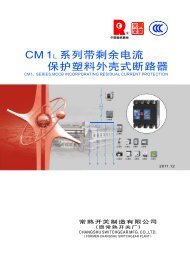
CW3G 系 列<br />
隔 离 开 关 (AC,DC)<br />
CM3DC 系 列<br />
塑 料 外 壳 式 断 路 器<br />
CH 系 列 小 型 断 路 器<br />
CE1 系 列<br />
智 能 型 电 力 仪 表<br />
CI1 系 列<br />
远 程 智 能 I/O 模 块<br />
CN1DP-MP<br />
CN1DP-MD<br />
CN1DP-MC<br />
通 信 适 配 器<br />
CN1EG 以 太 网<br />
适 配 器<br />
FDM3<br />
短 消 息 通 知 模 块<br />
FWB1 温 度 报 警 模 块<br />
CSJ1 系 列 剩 余 电 流 式 电 气<br />
火 灾 监 控 探 测 器 ( 独 立 式 )<br />
CMSJ2 系 列 剩 余 电 流 式 电 气<br />
火 灾 监 控 探 测 器 ( 非 独 立 式 )<br />
CSX1 电 气 火 灾 监 控 设 备<br />
●Riyear-PowerNet 配 电 监 控 系 统<br />
●FCX3 智 能 配 电 监 控 器
优 秀 特 色<br />
获 得 国 际 认 可 的 CB 证 书<br />
电 子 式 可 调 过 电 流 保 护 和 剩 余 电 流 保 护 一 体 化 产 品<br />
具 有 体 积 小 、 分 断 高 、 带 隔 离 和 多 功 能 集 成 等 特 点<br />
额 定 极 限 短 路 分 断 能 力 Icu:400V:50kA~100kA<br />
额 定 运 行 短 路 分 断 能 力 Ics:400V:35kA~65kA<br />
电 子 式 可 调 三 段 过 电 流 保 护 , 方 便 用 户 灵 活 使 用<br />
剩 余 电 流 保 护 三 相 取 电 : 常 规 的 带 剩 余 电 流 保 护 断 路 器 的 漏 电 保 护 模 块 工 作 电 源 取 样 为<br />
二 相 , 本 系 列 断 路 器 为 三 相 , 若 缺 任 一 相 , 断 路 器 漏 电 保 护 模 块 仍 能 正 常 工 作<br />
提 供 不 同 剩 余 电 流 动 作 脱 扣 器 可 选 , 应 用 范 围 可 从 30mA~30A 进 行 整 定<br />
额 定 剩 余 动 作 电 流 :I△n(A):0.03/0.1/0.3/0.5、0.1/0.3/0.5、0.3/0.5/1、0.3/1/3/10、<br />
1/3/10/30 可 调<br />
5I△n 最 大 断 开 时 间 △t(s): 瞬 动 /0.3/0.5/1/2 可 调<br />
具 有 较 强 功 能 扩 展 性 , 可 增 选 剩 余 电 流 报 警 模 块 , 实 现 脱 扣 报 警 输 出 或 不 脱 扣 报 警 输 出<br />
可 配 FWB1 温 度 报 警 模 块 , 实 现 连 接 点 在 线 超 温 报 警
目 录<br />
R<br />
概 述<br />
General<br />
正 常 使 用 条 件 和 安 装 条 件<br />
Normalservice andmountingconditions<br />
型 号 及 含 义<br />
Type and its meaning<br />
结 构 简 介<br />
Structureintroduction<br />
电 子 过 电 流 脱 扣 器 整 定 值<br />
Electronicovercurrentrelease setting value<br />
脱 扣 器 方 式 及 内 部 附 件 代 号<br />
Releasepatternandinternal accessories code<br />
主 要 技 术 性 能 指 标<br />
Maintechnical performance index<br />
功 耗 及 高 海 拔 降 容<br />
Powerloss and altitudederating<br />
电 子 式 过 电 流 脱 扣 器 保 护 特 性<br />
Protection characteristic of electronic overcurrent release<br />
剩 余 电 流 保 护 特 性 曲 线<br />
Residual currentprotectioncharacteristiccurve<br />
1<br />
2<br />
3<br />
5<br />
6<br />
8<br />
9<br />
10<br />
11<br />
13<br />
外 形 尺 寸 及 安 装 尺 寸<br />
Outlineand mounting dimensions<br />
断 路 器 安 装 安 全 间 隙<br />
Mounting safetyclearance<br />
15<br />
23<br />
内 外 部 附 件<br />
Internal/externalaccessories<br />
不 同 额 定 电 流 的 连 接 导 线 参 考 截 面<br />
Cross-sectionwiringconductorcorrespondingratedcurrent<br />
23<br />
34<br />
接 线 端 子 型 号<br />
Terminal Type<br />
34<br />
FWB1 温 度 报 警 模 块<br />
Temperaturealarm module<br />
35<br />
使 用 与 维 护<br />
Useandmaintenance<br />
37<br />
订 货 须 知<br />
Ordering notice<br />
订 货 规 范<br />
Ordering form<br />
37<br />
38
概 述 General<br />
<strong>CM1</strong><br />
EL<br />
系 列 带 剩 余 电 流 保 护 断 路 器 ( 以 下 简<br />
称 断 路 器 ), 是 本 公 司 采 用 国 际 先 进 设 计 、 制 造<br />
技 术 研 制 、 开 发 的 新 型 断 路 器 之 一 。 其 额 定 绝 缘<br />
电 压 为 800V, 适 用 于 交 流 50Hz/60Hz, 额 定 工 作<br />
电 压 400V 及 以 下 , 额 定 电 流 至 800A 的 电 路 中 作 不<br />
频 繁 转 换 及 电 动 机 保 护 之 用 。 断 路 器 具 有 过 载 长<br />
延 时 反 时 限 、 短 路 短 延 时 、 短 路 瞬 时 和 欠 电 压 保<br />
护 功 能 , 能 保 护 线 路 和 电 源 设 备 不 受 损 坏 , 同<br />
时 , 可 对 人 提 供 间 接 接 触 保 护 , 还 可 以 对 过 电 流<br />
保 护 不 能 检 测 出 的 长 期 存 在 的 接 地 故 障 可 能 引 起<br />
的 火 灾 危 险 提 供 保 护 。 在 其 它 保 护 装 置 失 灵 时 ,<br />
额 定 剩 余 动 作 电 流 为 30mA 的 <strong>CM1</strong><br />
断 路 器 可 对 直<br />
接 接 触 起 附 加 保 护 作 用 。<br />
断 路 器 按 照 其 额 定 极 限 短 路 分 断 能 力 (Icu) 的<br />
高 低 , 分 为 M 型 ( 较 高 分 断 型 )、H 型 ( 高 分 断 型 ) 两<br />
类 。 该 断 路 器 除 具 有 体 积 小 、 高 分 断 、 短 飞 弧 ( 部<br />
分 规 格 加 装 零 飞 弧 罩 后 可 实 现 零 飞 弧 )、 带 隔 离 、<br />
抗 震 动 等 特 点<br />
断 路 器 可 垂 直 安 装 ( 即 竖 装 ), 亦 可 水 平 安<br />
装 ( 即 横 装 )<br />
断 路 器 不 可 倒 进 线 , 即 只 能 1、3、5 接 电 源<br />
线 ,LOAD 接 负 载 线<br />
断 路 器 具 有 隔 离 功 能 , 其 相 应 的 符 号 为 :<br />
断 路 器 产 品 符 合 下 列 标 准 :<br />
IEC60947-1 及 GB14048.1-2006 低 压 开 关 设<br />
备 和 控 制 设 备 总 则<br />
IEC60947-2 及 GB14048.2-2008 低 压 开 关 设<br />
备 和 控 制 设 备 断 路 器 及 附 录 B 带 剩 余 电 流 保 护<br />
的 断 路 器 、 附 录 F 带 电 子 过 电 流 保 护 断 路 器 的 附<br />
加 试 验<br />
IEC60947-4-1 及 GB14048.4 低 压 开 关 设 备 和<br />
控 制 设 备 机 电 式 接 触 器 和 电 动 机 起 动 器<br />
● 断 路 器 获 国 家 强 制 性 产 品 认 证 “CCC” 标 志 。<br />
EL<br />
<strong>CM1</strong>EL<br />
series electronic adjustable MCCB<br />
incorporating residual current protection(hereafter<br />
simply reffered to as breakers) is one of the new type<br />
breakers which have been developed by the company<br />
using international design and manufacturing<br />
technology.The rated insulation voltage of breakers is<br />
800V,suitable for imfrequent chang-over switching and<br />
infrequent motor starting up in the circuit of<br />
AC50Hz/60Hz,rated operational voltage 400V or below<br />
and rated current up to 800A.The breakers have<br />
overload long-time-delay inverse,short-circuit shorttime<br />
delay,short-circuit instantaneous and undervoltage<br />
protection performances, concurrently, the<br />
breakers provide protection of persons against indirect<br />
contact,and provide protection against fire which may<br />
develop as aresult of an earth fault of alasting nature,<br />
which can't be detected by the over-current protective<br />
device.Additionally, when other protective devices fail<br />
to function,<strong>CM1</strong>EL<br />
breakers incorporating the rated<br />
residual operating current of 30mA can provide<br />
addintional protectionagainstdirect contact.<br />
●The breakers according to the rated ultimate shortcircuit<br />
breaking capacity(Icu), are classified two kinds<br />
of types:M(secondhigh type),H(high type).The breakers<br />
are of following characteristics: compact size,high<br />
breaking capacity,short arc-over distance(some<br />
breakers have zero arc distance by installing zero arc<br />
cover),isolationfunctionandagainstvibrations,etc.<br />
● The breakers could be installed vertically(upright)or<br />
horizontally(transverse).<br />
● The breakers can't be wired adversely, only1,3,5<br />
connected with supply line,LOAD connected with load<br />
line.<br />
● The breakers are applicable to isolation,its<br />
corresponding symbol is shownas<br />
.<br />
● The breakers comply with the demands of the<br />
followingstandards:<br />
IEC 60947-1and GB14048.1-2006 Low-voltage<br />
switchgear and controlgearGeneral rules<br />
IEC 60947-2 and GB14048.2-2008 Low-voltage<br />
switchgear and controlgear Circuit-breakers, annex B<br />
circuit-breakers incorporating residual current<br />
protection and annex F additional tests for circuitbreakerswith<br />
electronicover-currentprotection<br />
IEC60947-4-1 and GB 14048.4 Low-voltage<br />
switchgear and controlgear Electromechanical<br />
contactorsandmotor-starters<br />
●ThebreakershaveobtainedtheCCCmark<br />
of CQC.<br />
1
正 常 使 用 条 件 和 安 装 条 件<br />
NORMAL SERVICE AND MOUNTING CONDTIONS<br />
●周 围 空 气 温 度 不 超 过 +40℃ 和 不 低 于 -5<br />
℃, 且 24h 的 平 均 值 不 超 过 +35℃;<br />
●安 装 地 点 的 海 拔 不 超 过 2000m;<br />
●安 装 地 点 的 空 气 相 对 湿 度 在 最 高 温 度 为 +<br />
40℃ 时 不 超 过 50%, 在 较 低 温 度 下 可 以 有 较 高 的<br />
相 对 湿 度 , 例 如 20℃ 时 达 90%。 对 于 温 度 变 化 偶<br />
尔 产 生 的 凝 露 应 采 取 特 殊 措 施 ;<br />
●污 染 等 级 为 3 级 ;<br />
●断 路 器 主 电 路 安 装 类 别 为 Ⅲ, 其 余 辅 助 电<br />
路 、 控 制 电 路 安 装 类 别 为 Ⅱ;<br />
●断 路 器 适 用 于 电 磁 环 境 A;<br />
●断 路 器 应 安 装 在 无 爆 炸 危 险 和 无 导 电 尘<br />
埃 、 无 足 以 腐 蚀 金 属 和 破 坏 绝 缘 的 地 方 ;<br />
●断 路 器 应 安 装 在 没 有 雨 雪 侵 袭 的 地 方 。<br />
● The ambient air temperature does not exceed+<br />
40℃ and its average over a period of 24h does not<br />
exceed + 35℃ ,the lower limit ofthe ambient air<br />
temperatureis-5℃;<br />
● The altitude of the site of installation does not<br />
exceed2000m;<br />
● The relative humidity of the air does not exceed<br />
50% at a maximum temperature of +40 ℃ , hogher<br />
relative humidities may be permitted at lower<br />
temperature,e.g.90% at +20℃. Specical measures may<br />
benecessary in cases of occasinonalcondensation due to<br />
variations in temperature;<br />
● Pollutiondegree3;<br />
● Installing category: III for themain circuit,and II<br />
forother auxiliaryand control circuits;<br />
● The breaker has been designedfor environment A;<br />
● There must be not any explosive dangrous and not<br />
any conduting dust, there must be not any gas which<br />
wouldcorrodemetal anddestroyinsulation;<br />
● The placewouldnotbeinvadedby rainand snow.<br />
2
型 号 及 含 义<br />
Type and its meaning<br />
C M 1 EL — □ □ □ / □ □ □<br />
□<br />
注 :1) 直 接 操 作 无 代 号 ; 电 动 机 操 作 用 P 表 示 ; 手 动 操 作 机 构 用 Z 表 示 。<br />
2) 配 电 用 断 路 器 无 代 号 ; 保 护 电 动 机 用 断 路 器 以 2 表 示 。<br />
3 ) 不 带 漏 电 报 警 单 元 模 块 无 代 号 , 带 漏 电 报 警 单 元 模 块 并 在 工 作 方 式 一 时 用 I 表 示 , 在 工 作 方 式<br />
二 时 用 II 表 示 。<br />
3)<br />
漏 电 报 警 单 元 模 块<br />
Leakage alarm unit Module<br />
2)<br />
用 途 代 号<br />
Usagecode<br />
脱 扣 器 方 式 及 附 件 代 号<br />
Releasepattern and accessoriescode<br />
极 数<br />
Numbersofpoles<br />
操 作 方 式<br />
1)<br />
Operatingpattern<br />
短 路 分 断 能 力 级 别<br />
short-circuitbreakingcapacity class<br />
壳 架 等 级 额 定 电 流<br />
framesizeratedcurrent<br />
电 子 式 过 电 流 脱 扣 器 并 带 剩 余 电 流 保 护<br />
Electronicovercurrentrelease incorporating residual<br />
current protection<br />
设 计 代 号<br />
Design code<br />
塑 料 外 壳 式 断 路 器<br />
Mouldedcase circuit breaker<br />
常 熟 开 关 制 造 有 限 公 司<br />
Changshu switchgear Mfg.co.,Ltd<br />
Note:1)Nocodeforoperation directly;Pfor motor operator;Zforrotary handle operator.<br />
2)UsagecodefordistributionMCCB is withoutcode,usagecodeformotorprotectionis two.<br />
3)leakage without alarm unit module without code;with such as Iwhen in workingmethod one; as<br />
inworkingmethodtwo.<br />
II when<br />
3
型 号 及 含 义 Type and its meaning<br />
按 产 品 极 数 分 为 三 极 与 四 极 。 四 极 产 品 中 性<br />
极 (N 极 ) 的 型 式 为 :N 极 过 电 流 保 护 电 流 、 时 间 参<br />
数 100% 自 动 跟 踪 相 线 整 定 值 , 且 N 极 与 其 它 三 极<br />
一 起 合 分 (N 极 先 合 后 分 )。<br />
按 额 定 电 流 分 :<strong>CM1</strong>EL-100 为 32、 63、<br />
100A;<strong>CM1</strong>EL-250 为 250A; <strong>CM1</strong>EL-400 为 400A;<br />
<strong>CM1</strong>EL-800 为 630、800A。<br />
按 接 线 方 式 分 为 板 前 接 线 、 板 后 接 线 、 插 入<br />
式 板 前 接 线 、 插 入 式 板 后 接 线 四 种 。<br />
附 件 分 内 部 附 件 和 外 部 附 件 : 内 部 附 件 有 分<br />
励 脱 扣 器 、 欠 电 压 脱 扣 器 、 辅 助 触 头 、 报 警 触<br />
头 、 漏 电 报 警 单 元 模 块 五 种 , 外 部 附 件 有 手 动 操<br />
作 机 构 、 电 动 机 操 作 机 构 、 手 持 式 <strong>CM1</strong>E 专 用 测<br />
试 器 、FWB1 温 度 报 警 模 块 等 。<br />
According to the pole numbers of product, it<br />
classifies three and four-poles. The pattern of neutral<br />
pole(N) for four poles breaker as follows:protective<br />
current and time parameters of over-current in N<br />
pole,100% automatic tracking phase,and N pole<br />
combining with other three poles(Closing first and<br />
opening last).<br />
Classification according to rated current:<strong>CM1</strong>EL-<br />
100 has 32、63、100A;<strong>CM1</strong>EL-250 has 250A;<strong>CM1</strong>EL-<br />
400has400A; <strong>CM1</strong>EL-800 has630、800A.<br />
Theconnectedmode hasfour:frontconnected, rear<br />
connected, plug-in front connected and plug-in rear<br />
connected.<br />
The accessories can be classified into internal and<br />
external accessories.The internal accessories have five<br />
kinds of shunt release,under-voltage release, auxiliary<br />
contact,alarm contact and leakage alarm unit<br />
module;the external accessories have rotary handle<br />
operator,motor operator and <strong>CM1</strong>E tester、<br />
temperature<br />
alarm module.<br />
4
0 1<br />
结 构 简 介<br />
Structureintroduction<br />
接 线 端 子<br />
Terminal<br />
铭 牌<br />
Nameplate<br />
脱 扣 按 钮<br />
Trippingpushbutton<br />
漏 电 指 示 / 复 位 钮<br />
Leakageindicating/resetbutton<br />
1 3 5<br />
常 熟 开 关 制 造 有 限 公 司<br />
带 剩 余 电 流 保 护<br />
R 断 路 器<br />
<strong>CM1</strong>EL-100H /3300<br />
额 定 工 作 电 压 Ue<br />
额 定 绝 缘 电 压 Ui<br />
额 定 冲 击 耐 受 电 压 Ui mp<br />
额 定 频 率<br />
额 定 电 流 In<br />
整 定 电 流 Ir 1<br />
使 用 类 别<br />
PUSHTOTRIP<br />
2008 年 11 月<br />
A<br />
AC400<br />
800V<br />
8kV<br />
50Hz/60Hz<br />
100A<br />
63~100A<br />
电 子 式 过 电 流 脱 扣 器<br />
In=100A<br />
ON<br />
ON<br />
OFF<br />
70 75<br />
65<br />
63<br />
100<br />
过 载<br />
预 报 警<br />
短 路 分 断 能 力<br />
AC Icu Ics<br />
400V 85kA50kA<br />
符 合 标 准<br />
GB14048.2<br />
IEC60947-2<br />
常 熟 开 关 制 造 有 限 公 司<br />
( 原 常 熟 开 关 厂 )<br />
Ir (A)<br />
Ir (XIr1)<br />
2 1 t1(S) t2(s) Ir(XIr)<br />
3 1 Ir(XIr)<br />
2 4 6<br />
80<br />
85<br />
90<br />
95<br />
60<br />
80<br />
4 5 6<br />
3<br />
12 2.5<br />
100 2 12 10 87<br />
0.06<br />
0.1<br />
0.2<br />
0.3<br />
6 7 8 10 11<br />
12<br />
13<br />
4 16 14<br />
0.75 0.8 0.85 0.9<br />
0.95<br />
0.7<br />
1<br />
外 壳<br />
Enclosure<br />
操 作 手 柄<br />
Operatinghandle<br />
指 示 灯<br />
Pilot light<br />
电 流 、 时 间 调 节 旋 钮<br />
Current、timeadjustableturnbutton<br />
额 定 剩 余 动 作 电 流 调 节<br />
rated residual operating current adjustable<br />
最 大 断 开 时 间 调 节<br />
Maximunbreaktimeadjustable<br />
剩 余 电 流 脱 扣 器 V 型 In=100A<br />
额 定 剩 余 动 作 电 流 In(mA) 延 时 型 :5In 最 大 断 开 时 间 ( ms)<br />
500<br />
延 时 1000<br />
漏 电 试 验 按 钮<br />
2I△n 极 限 不 驱 动 时 间 △t100/200/500/1000ms<br />
300<br />
! 当 剩 余 电 流 保 护 动 作 后 , 须 先 按 下<br />
500 500 2000 T<br />
复 位 按 钮 进 行 复 位 , 断 路 器 才 能 再 扣 合 闸 。 100 非 延 时 300<br />
LOAD<br />
漏 电 试 验 按 钮<br />
leakage testpushbutton<br />
漏 电 延 时 / 非 延 时 切 换<br />
Leakagetime-delay/non-time-delayswitch<br />
5
电 子 式 过 电 流 脱 扣 器 整 定 值<br />
Electronicovercurrentrelease settingvalue<br />
<strong>CM1</strong>EL -100,In=32A 电 子 式 过 电 流 脱 扣 器<br />
电 子 式 过 电 流 脱 扣 器 保 护 特 性 曲 线<br />
Electronicovercurrent release<br />
16<br />
20<br />
I r1(A)<br />
1<br />
25<br />
32<br />
12<br />
60<br />
2<br />
t(s) 1<br />
80<br />
100<br />
3<br />
4 5 6<br />
3<br />
2.5<br />
0.06<br />
2 12 1087<br />
I r2(XI r1)<br />
0.1<br />
4<br />
t(s) 2<br />
0.2<br />
0.3<br />
5<br />
TEST<br />
6 7 8 10 11<br />
12 0.75 0.8 0.85 0.9<br />
0.95<br />
13 0.7<br />
4 16 14<br />
1<br />
I r3(XI r1)<br />
I ro(XI r1)<br />
6<br />
7<br />
Protectivecharacteristic curveofelectronic overcurrentrelease<br />
t<br />
1<br />
2<br />
3<br />
4<br />
5<br />
o<br />
Ir1 Ir2<br />
Ir3<br />
I<br />
<strong>CM1</strong>EL -100,In=63A 电 子 式 过 电 流 脱 扣 器<br />
电 子 式 过 电 流 脱 扣 器 保 护 特 性 曲 线<br />
Electronic overcurrentrelease Protectivecharacteristic<br />
curveofelectronic overcurrentrelease<br />
1<br />
2<br />
3<br />
4<br />
5<br />
6 7<br />
40<br />
36<br />
32<br />
45 50<br />
55<br />
60<br />
63<br />
I r1(A)<br />
12<br />
60<br />
t(s) 1<br />
80<br />
100<br />
4 5 6<br />
3<br />
2.5<br />
0.06<br />
2 12 10 87<br />
I r2(XI r1)<br />
0.1<br />
t(s) 2<br />
0.2<br />
0.3<br />
TEST<br />
6 7 8 10 11<br />
12<br />
13<br />
4 16 14<br />
I r3(XI r1)<br />
0.75 0.8 0.85 0.9<br />
0.95<br />
0.7<br />
1<br />
I ro(XI r1)<br />
t<br />
1<br />
2<br />
3<br />
4<br />
5<br />
o<br />
Ir1 Ir2<br />
Ir3<br />
I<br />
<strong>CM1</strong>EL -100,In=100A 电 子 式 过 电 流 脱 扣 器<br />
电 子 式 过 电 流 脱 扣 器 保 护 特 性 曲 线<br />
Electronic overcurrentrelease<br />
Protectivecharacteristic<br />
curveofelectronic overcurrentrelease<br />
1 2<br />
3<br />
4<br />
5<br />
6 7<br />
70 75 80<br />
65 85<br />
63 90<br />
100 95<br />
I r1(A)<br />
60<br />
80<br />
4 5 6 0.1<br />
3<br />
12 2.5<br />
100 2 12 10 87 0.06<br />
t(s) 1<br />
I r2(XI r1)<br />
t(s) 2<br />
0.2<br />
0.3<br />
TEST<br />
6 7 8 10 11<br />
12<br />
13<br />
4 16 14<br />
I r3(XI r1)<br />
0.75 0.8 0.85 0.90.95<br />
0.7<br />
1<br />
I ro(XI r1)<br />
t<br />
1<br />
2<br />
3<br />
4<br />
5<br />
o<br />
Ir1 Ir2<br />
Ir3<br />
I<br />
<strong>CM1</strong>EL<br />
-250,In=250A 电 子 式 过 电 流 脱 扣 器<br />
Electronic overcurrentrelease<br />
7<br />
TEST<br />
1<br />
125 140 150<br />
160<br />
180<br />
100 200<br />
250 225<br />
I r1(A)<br />
12<br />
60<br />
2<br />
t(s) 1<br />
3<br />
4 5<br />
0.1<br />
80<br />
6<br />
3<br />
2.5 0.06<br />
100 2 12 10 87<br />
I r2(XI r1)<br />
4<br />
t(s) 2<br />
0.2<br />
0.3<br />
5<br />
6 7 8 9 10 11<br />
12<br />
4 14 13<br />
I r3(XI r1)<br />
6<br />
0.75 0.8 0.85 0.9 0.95<br />
0.7 1<br />
I ro(XI r1)<br />
电 子 式 过 电 流 脱 扣 器 保 护 特 性 曲 线<br />
Protectivecharacteristic<br />
curveofelectronic overcurrentrelease<br />
t 1<br />
2<br />
3<br />
4<br />
5<br />
o Ir1 Ir2 Ir3 I<br />
6
电 子 式 过 电 流 脱 扣 器 整 定 值<br />
Electronicovercurrentrelease settingvalue<br />
<strong>CM1</strong>EL -400,In=400A 电 子 式 过 电 流 脱 扣 器<br />
电 子 式 过 电 流 脱 扣 器 保 护 特 性 曲 线<br />
Electronic overcurrentrelease<br />
7 1 2<br />
3<br />
4<br />
5<br />
6<br />
Protectivecharacteristic<br />
curveofelectronic overcurrentrelease<br />
t<br />
1<br />
TEST<br />
250 280 315 60<br />
225 350<br />
12<br />
200<br />
400<br />
I r1(A)<br />
t(s) 1<br />
4 5<br />
6 0.1<br />
8 9<br />
100<br />
0.2<br />
10<br />
3<br />
0.75 0.8 0.85 7<br />
0.9<br />
0.06<br />
0.95<br />
2.5 6<br />
150 2 0.3 4<br />
0.7<br />
12 10 87<br />
11<br />
14 1312 1<br />
I r2(XI r1)<br />
t(s) 2<br />
I r3(XI r1)<br />
I ro(XI r1)<br />
o<br />
2<br />
3<br />
4<br />
Ir1 Ir2 Ir3<br />
5<br />
I<br />
<strong>CM1</strong>EL -800,In=630A 电 子 式 过 电 流 脱 扣 器<br />
电 子 式 过 电 流 脱 扣 器 保 护 特 性 曲 线<br />
Electronicovercurrent release<br />
7 1<br />
2<br />
3<br />
4<br />
5<br />
6<br />
Protectivecharacteristic<br />
curveofelectronic overcurrentrelease<br />
TEST<br />
460 480 500<br />
440 530<br />
420 560 12<br />
400 630 600<br />
I r1(A)<br />
60<br />
t(s) 1<br />
4 5 0.1<br />
100<br />
6<br />
3<br />
2.5<br />
0.06<br />
150 2 12 10 87<br />
I r2(XI r1)<br />
t(s) 2<br />
0.2<br />
0.3<br />
0.75 0.8 0.85 0.9<br />
0.95<br />
6 7 8 9 10<br />
11<br />
4<br />
0.7<br />
14 13 12<br />
1<br />
I r3(XI r1)<br />
I ro(XI r1)<br />
t<br />
o<br />
1<br />
2<br />
3<br />
4<br />
Ir1 Ir2 Ir3<br />
5<br />
I<br />
<strong>CM1</strong>EL -800,In=800A 电 子 式 过 电 流 脱 扣 器<br />
电 子 式 过 电 流 脱 扣 器 保 护 特 性 曲 线<br />
Electronicovercurrent release<br />
7 1<br />
2<br />
3<br />
4 5<br />
6<br />
Protectivecharacteristic<br />
curveofelectronic overcurrentrelease<br />
TEST<br />
680<br />
660<br />
640<br />
630 800<br />
I r1(A)<br />
700 720 60 3.5 4<br />
100 5 0.1<br />
0.2<br />
0.75 0.8 0.85 0.9 740<br />
12<br />
3<br />
6 7 8 9<br />
0.06<br />
0.95<br />
760 2.5 5<br />
780<br />
150 2<br />
0.3<br />
0.7<br />
4 12 11<br />
10<br />
1<br />
t(s) 1<br />
10 8 76<br />
I r2(XI r1)<br />
t(s) 2<br />
I r3(XI r1)<br />
I ro(XI r1)<br />
t<br />
o<br />
1<br />
2<br />
3<br />
4<br />
Ir1 Ir2 Ir3<br />
5<br />
I<br />
1- 过 载 长 延 时 动 作 电 流 Ir 1调 整 , 根 据 断 路 器 不 同 的<br />
额 定 电 流 , 可 从 4 档 到 10 档 进 行 调 整 ;<br />
2- 长 延 时 动 作 时 间 t 1调 整 , 可 进 行 4 档 调 整 ;<br />
3- 短 路 短 延 时 动 作 电 流 Ir 2调 整 , 可 进 行 10 档 调 整 ;<br />
4- 短 延 时 动 作 时 间 t 2调 整 , 可 进 行 4 档 调 整 ;<br />
1-Forthe adjustmentof overload long-time delay operating<br />
currentIr1,accordingto differentrated currentthisknob can be<br />
adjusted from 4stepsto 10steps;<br />
2-Forthe adjustmentof long-time operating time t1, thisknob<br />
can beadjusted 4steps;<br />
3-Forthe adjustmentof short-circuitshort-time delay operating<br />
currentIr2,thisknobcan be adjusted10 steps;<br />
4-Forthe adjustmentof short-time operating time t2, thisknob<br />
5- 短 路 瞬 时 动 作 电 流 Ir 3调 整 , 可 进 行 9档 或 10 档 调<br />
整 ;<br />
6- 预 报 警 动 作 电 流 Ir 0调 整 , 可 进 行 7 档 调 整 ;<br />
7- 测 试 端 , 用 于 检 测 电 子 过 电 流 脱 扣 器 当 前 整 定 值 。<br />
can be adjusted4steps;<br />
5-For the adjustmentof short-circuitinstantaneousoperating<br />
current Ir3, thisknob canbe adjusted 9stepsor10 steps;<br />
6-For the adjustmentof pre-alarm operating current Ir0, this<br />
knobcan be adjusted7steps;<br />
7-Test terminalfor the testingof persentsetting value of<br />
electronic overcurrent release.<br />
7
脱 扣 器 方 式 及 内 部 附 件 代 号<br />
Release pattern and internal accessories code<br />
左 面 安 装<br />
Leftinstallation<br />
手 柄<br />
Handle<br />
右 面 安 装<br />
Right installation<br />
报 警 触 头<br />
辅 助 触 头<br />
分 励 脱 扣 器<br />
欠 电 压 脱 扣 器<br />
引 线 方 向<br />
Alarm contact<br />
Auxiliary contact<br />
Shunt release<br />
Under voltage release<br />
Lead direction<br />
脱 扣 器<br />
方 式 及 内<br />
部 附 件 代 号<br />
Release pattern and<br />
accessoriescode<br />
308<br />
310<br />
320<br />
330<br />
340<br />
350<br />
360<br />
370<br />
318<br />
328<br />
338<br />
348<br />
368<br />
378<br />
型 号 Type<br />
极 数 Numbers ofpole<br />
附 件 名 称<br />
Accessories name<br />
报 警 触 头<br />
Alarmcontact<br />
分 励 脱 扣 器<br />
Shuntcontact<br />
辅 助 触 头<br />
Auxiliary switch<br />
欠 电 压 脱 扣 器<br />
Undervoltagerelease<br />
分 励 脱 扣 器 辅 助 触 头<br />
Shuntrelease Auxiliary contact<br />
分 励 脱 扣 器 欠 电 压 脱 扣 器<br />
Shuntrelease Undervoltagerelease<br />
二 组 辅 助 触 头<br />
TwoAuxiliarycontact<br />
辅 助 触 头 欠 电 压 脱 扣 器<br />
Auxiliary contactUndervoltagerelease<br />
分 励 脱 扣 器<br />
Shuntrelease<br />
报 警 触 头<br />
Alarm contact<br />
辅 助 触 头 报 警 触 头<br />
Auxiliary contact Alarmcontact<br />
欠 电 压 脱 扣 器 报 警 触 头<br />
Undervoltage release Alarmcontact<br />
分 励 脱 扣 器 辅 助 触 头 报 警 触 头<br />
Shunt release Auxiliary switch Alarm switch<br />
二 组 辅 助 触 头 报 警 触 头<br />
TwoauxiliarycontactAlarmcontact<br />
辅 助 触 头 欠 电 压 脱 扣 器 报 警 触 头<br />
Auxiliarycontact Undervoltage release Alarm contact<br />
<strong>CM1</strong>EL-100<br />
<strong>CM1</strong>EL-250<br />
3 极 、4 极<br />
<strong>CM1</strong>EL-400<br />
<strong>CM1</strong>EL-800<br />
3 极 4 极 3 极 、4 极<br />
Threepoles、fourpoles Threepoles Fourpoles Threepoles、fourpoles<br />
注 :1. 脱 扣 器 方 式 及 内 部 附 件 代 号 首 位 数 字 3 表 示 具 有 三 段 过 电 流 保 护 的 电 子 式 脱 扣 器 ; 后 两 位 数 字 表 示 内 部 附 件 代 号 , 无 附 件 则 用 00 表 示 ;<br />
2. 对 <strong>CM1</strong>EL-400 中 328 规 格 、<strong>CM1</strong>EL-800 中 348 规 格 的 辅 助 触 头 为 一 对 触 头 ( 即 一 常 开 , 一 常 闭 ),<strong>CM1</strong>EL-400、<strong>CM1</strong> EL-800 中 368 规 格 的<br />
辅 助 触 头 为 三 对 触 头 ( 即 三 常 开 , 三 常 闭 ); 其 余 规 格 辅 助 触 头 的 触 头 数 按 第 26 页 表 中 配 置 ;<br />
3. 对 <strong>CM1</strong>EL-100、250 中 320 规 格 辅 助 触 头 可 提 供 二 对 触 头 ( 即 二 常 开 , 二 常 闭 ), 但 须 在 订 货 时 注 明 。<br />
Note:1. Firstnumberthree ofrelease pattern andinternalaccessories codeis providedwiththreelevelovercurrentprotectiveelectronic release;the last<br />
two numbers areprovidedaccessriescode.No accessory thecode is00.<br />
2. For<strong>CM1</strong>EL -400code328, <strong>CM1</strong>EL-800code348only haveone pairofauxiliarycontact(one NOand one NC).For<strong>CM1</strong>EL-400, <strong>CM1</strong>EL-800 code<br />
328onlyhavethree pairs ofauxiliarycontacts(threeNOandthreeNC). Theamountofauxiliary contacts in termsof otherspecifications is<br />
disposedaccords tothe diagramsonpage26.<br />
3. For<strong>CM1</strong>EL-100,250code 320.Two pairs ofauxiliary contactsare provided,note whenmaking order.<br />
8
主 要 技 术 性 能 指 标<br />
Main technicalperformanceindex<br />
型 号 Type<br />
壳 架 等 级 额 定 电 流 Inm (A)<br />
Framesizerated current<br />
额 定 电 流 I n (A)<br />
Rated current<br />
过 载 长 延 时 整 定 电 流 Ir 1 (A)<br />
Over load Long-timedelay<br />
极<br />
数 Numberofpoles<br />
额 定 工 作 电 压 Ue (V)<br />
Ratedoperationalvoltage<br />
额 定 绝 缘 电 压 Ui (V)<br />
Rated insulation voltage<br />
额 定 冲 击 耐 受 电 压 Uimp (V)<br />
Rated inpulsewithstand voltage<br />
分 断 能 力 级 别<br />
Breakingcapacity class<br />
额 定 极 限 短 路 分 断 能 力 Icu(kA)<br />
Ratedultimateshort-circuit<br />
breakingcapacity<br />
W<br />
H<br />
板 后 接 线 Rearconnected<br />
W<br />
插 入 式 接 线 Plug-in connected<br />
L<br />
H<br />
欠 电 压 脱 扣 器 Undervoltagerelease<br />
分 励 脱 扣 器 Shunt release<br />
辅 助 触 头 Auxiliary contact<br />
报 警 触 头 Alarm contact<br />
AC400V<br />
额 定 运 行 短 路 分 断 能 力 Ics(kA)<br />
Ratedservice short-circuit AC400V<br />
breakingcapacity<br />
额 定 短 时 耐 受 电 流 Icw(kA)/1s<br />
Rated short-time withstand current<br />
使 用 类 别 Utilization category<br />
额 定 剩 余<br />
动 作 电 流<br />
U 型 , 非 延 时<br />
TypeU,non-time-delay<br />
V 型 , 非 延 时 、 延 时 可 调<br />
I△n(A)<br />
Type V, Non-time-delay、 time-delay adjustable<br />
Rated residual W 型 , 非 延 时 、 延 时 可 调<br />
operatingcurrent TypeW, Non-time-delay、 time-delay adjustable<br />
额 定 剩 余 不 动 作 电 流 I△n(A)<br />
0<br />
Rated residual non-operating current<br />
额 定 剩 余 短 路 接 通 ( 分 断 ) 能 力 I△m(kA)<br />
Rated residual short-circuitmaking(breaking) capacity<br />
飞 弧 距 离 (mm)<br />
Arc-over distance<br />
电 气 寿 命 **<br />
Electricaldurability<br />
机 械 寿 命 **<br />
Mechanicaldurability<br />
外 形<br />
尺 寸<br />
(mm)<br />
Outline<br />
dimensions<br />
板 前 接 线 Front connected<br />
免 维 护<br />
Freemaintenance<br />
有 维 护<br />
Maintenance<br />
电 动 机 操 作 机 构<br />
Motoroperator<br />
手 动 操 作 机 构<br />
Rotary handle operator<br />
<strong>CM1</strong> E专 用 测 试 器<br />
<strong>CM1</strong>E tester<br />
漏 电 报 警 单 元 模 块<br />
Leakage alarm unit module<br />
<strong>CM1</strong>EL-100<br />
<strong>CM1</strong>EL-800<br />
100 250<br />
400<br />
800<br />
32 63 100<br />
16,20,<br />
25,32<br />
32,36,40,<br />
45,50,55,<br />
60,63<br />
3,4<br />
63,65,70,<br />
75,80,85,<br />
90,95,100<br />
<strong>CM1</strong>EL-250<br />
250<br />
100,125,140,150,<br />
160,180,200,225,250<br />
3,4<br />
AC400<br />
AC800<br />
8000<br />
<strong>CM1</strong>EL-400<br />
M H M H M H M<br />
50 85 50 85<br />
35 50 35 50<br />
A<br />
0.03/0.1/0.3/0.5<br />
400<br />
200,225,250,<br />
280,315,350,400<br />
630 800<br />
3,4 3,4<br />
0.1/0.3/0.5 0.1/0.3/0.5 0.1/0.3/0.5 0.3/0.5/1<br />
0.3/1/3/10 0.3/1/3/10 1/3/10/30 1/3/10/30<br />
≯50(0)*<br />
B<br />
≯100(0)*<br />
B<br />
≯100<br />
8000 8000<br />
7500 7500<br />
20000 20000<br />
10000 10000<br />
40000 40000<br />
20000<br />
20000<br />
92/122( 三 极 / 四 极 )<br />
150/198( 三 极 / 四 极 ) 210/280( 三 极 / 四 极 )<br />
215 240<br />
357 400<br />
92 90<br />
106.5 115.5<br />
○<br />
○<br />
○<br />
○<br />
○<br />
○<br />
○<br />
○<br />
○<br />
○<br />
○<br />
A<br />
0.03/0.1/0.3/0.5<br />
≯50(0)*<br />
1<br />
2<br />
1<br />
4<br />
I△n<br />
Icu<br />
107/142( 三 极 / 四 极 )<br />
65<br />
42<br />
○<br />
○<br />
○<br />
○<br />
○<br />
○<br />
○<br />
○<br />
○<br />
○<br />
○<br />
100<br />
65<br />
400,420,440,460,480,<br />
500,530,560,600,630<br />
75<br />
50<br />
5 10<br />
(Three/fourpoles) (Three/fourpoles) (Three/fourpoles) (Three/fourpoles)<br />
○<br />
○<br />
○<br />
○<br />
○<br />
○<br />
○<br />
○<br />
○<br />
○<br />
○<br />
○<br />
○<br />
○<br />
○<br />
○<br />
○<br />
○<br />
○<br />
○<br />
○<br />
○<br />
630,640,660,680,700,<br />
720,740,760,780,800<br />
H<br />
100<br />
65<br />
* 注 : 选 装 高 为 6mm(<strong>CM1</strong>EL-100)、7.5mm(<strong>CM1</strong>EL-250)、9.3mm(<strong>CM1</strong>EL-400) 的 零 飞 弧 罩 , 实 现 零 飞 弧 。<br />
** 注 : 按 GB14048.1-2006, 术 语 “ 寿 命 ” 表 示 电 器 在 修 理 或 更 换 部 件 前 能 完 成 的 操 作 循 环 次 数 的 概 率 。<br />
1. 本 系 列 三 极 断 路 器 接 三 相 负 载 时 , 负 载 不 能 带 中 性 线 , 包 括 取 自 断 路 器 负 载 端 的 负 载 控 制 回 路 电 源 也 不 能 带 中 性 线 , 否 则 该 断 路 器<br />
会 产 生 误 动 作 。<br />
2. 本 系 列 三 极 和 四 极 断 路 器 接 单 相 负 载 时 , 相 线 接 A 极 , 中 性 线 接 C 极 , 不 要 接 B 极 。<br />
*Note:zeroarcventingbyinstallingzero arcventing cover are of6mm(<strong>CM1</strong>EL-100)、7.5mm(<strong>CM1</strong>EL-250)、9.3mm(<strong>CM1</strong>EL-400).<br />
**Note:The term "durability" expresses theexpectancyofthe number ofoperating cycles whichcanbe performed bythe equimentbeforerepair or replacementof<br />
parts.<br />
1.Theloadcan'thave neutralwire,including thepower supplyof theloadmonitor circuitfrom thebreakers'loadterminals.Whenthis seriesthree poles<br />
breakers connecting withthree-phasesload,or the breakerswillbemisoperation.<br />
2.Whenthis series three-poles andfour-poles breakers connecting withsinglephase load,the phaseline is connectedwithApole,and neutralline is<br />
connected withCpole, withBpoleempty.<br />
9
功 耗 及 高 海 拔 降 容<br />
Powerloss andaltitude derating<br />
功 耗<br />
Powerloss<br />
型 号<br />
Type<br />
通 电 电 流 (A)<br />
Withcurrent<br />
板 前 、 板 后 接 线<br />
Front/rearconnected<br />
三 极 / 四 极 总 功 率 损 耗 (W)<br />
Thetotalpowerloss ofthree poles/fourpoles<br />
插 入 式 板 前 接 线<br />
Plug-in front connected<br />
插 入 式 板 后 接 线<br />
Plug-in rear connected<br />
<strong>CM1</strong>EL-100<br />
100 17 17.1 17.2<br />
<strong>CM1</strong>EL-250<br />
250 48.8 48.9 49<br />
<strong>CM1</strong>EL-400<br />
400<br />
76.8<br />
76.9<br />
77.1<br />
<strong>CM1</strong>EL-800<br />
800<br />
153.6<br />
153.7<br />
153.9<br />
海 拔 超 过 适 用 工 作 环 境 2000m, 断 路 器 电 气 性 能 可 参 照 下 表 修 正 :<br />
Altitudeof serviceenvironmentmorethan applicationof2000m,electricalperformanceof breakercan<br />
be corrected accordingtofollowing table:<br />
海 拔 (m)<br />
Altitude<br />
工 频 耐 压 (V)<br />
Power-frequency withstand voltage<br />
工 作 电 流 修 正 系 数<br />
operationalcurrentcorrection coeffient<br />
2000 3000 4000 5000<br />
3000 2500 2000 1800<br />
1 0.94 0.88 0.83<br />
10
电 子 式 过 电 流 脱 扣 器 保 护 特 性<br />
Protection characteristic of electronic overcurrent release<br />
断 路 器 内 装 按 有 效 值 采 样 的 电 流 传 感 器 。 断 路 器 具 有 过 载 长 延 时 反 时 限 、 短 路 短 延 时 反 时 限 、 短 路<br />
短 延 时 定 时 限 、 短 路 瞬 时 等 保 护 功 能 , 可 由 用 户 自 行 设 定 组 成 所 需 的 保 护 特 性 ; 中 性 线 过 电 流 保 护 电<br />
流 、 时 间 参 数 100% 自 动 跟 踪 相 线 整 定 值 。 脱 扣 器 特 性 见 下 图 。<br />
Thebreaker forwhich the currentsensing meansarestated to be r.m.s.responsive.ithasoverload long-time-delayinverse,<br />
short-circuit short-timedelay inverse,short-circuitshort-time delaydefinitr,short-circuitinstantaneous protection<br />
function, can be setupprotectionwhich is madeupby theusers;neutralovercurrent protectivecurrent,and time parameter<br />
100%automatic trackingphase settingvalue.see thefollowingdiagramofreleasecharacteristic.<br />
4h<br />
2h<br />
1h<br />
动<br />
作<br />
时<br />
间<br />
30m<br />
20m<br />
14m<br />
10m<br />
6m<br />
4m<br />
2m<br />
1m<br />
30s<br />
20s<br />
10s<br />
5s<br />
2s<br />
150s<br />
100s<br />
80s<br />
60s<br />
12s<br />
长 延 时 动 作 电 流 Ir1<br />
Long-time delay operatingcurrent<br />
长 延 时 动 作 时 间 t 1±20%<br />
Long-time delay operatingtime<br />
(12-150)s<br />
短 延 时 动 作 电 流 Ir 2±10%<br />
Short-timedelayoperatingcurrent<br />
(2-12)Ir1<br />
1s<br />
0.5s<br />
0.2s<br />
0.1s<br />
短 延 时 动 作 时 间 t2<br />
Short-timedelay operatingtime<br />
0.3±0.06s<br />
0.2±0.04s<br />
0.1±0.03s<br />
0.06±0.02s<br />
0.05s<br />
0.02s<br />
0.01s<br />
瞬 时 动 作 电 流 Ir3<br />
Instantaneousoperating current<br />
(4-16)Ir 1±15%<br />
最 大 瞬 时 动 作 时 间<br />
Maximum instantaneous operating time<br />
0.6<br />
0.7<br />
1<br />
1.3<br />
2<br />
3<br />
4<br />
5<br />
6<br />
7<br />
10 12<br />
15<br />
20<br />
30<br />
40<br />
电 流 (×Ir 1)(A)<br />
Current<br />
11
电 子 式 过 电 流 脱 扣 器 保 护 特 性<br />
Protection characteristic of electronic overcurrent release<br />
长 延 时 过 电 流 保 护 反 时 限 动 作 特 性 见 表 。<br />
Long-time-delay overcurrentprotectiveinverse operating charateristicseefollowing table<br />
电<br />
流 Current<br />
1.05Ir1<br />
动 作 时 间<br />
Operating time<br />
2 小 时 内 不 动 作<br />
Non-operating within twohour<br />
配<br />
电<br />
用<br />
1.3Ir1<br />
2Ir1<br />
整 定 时 间 t(s) 1<br />
Setting time<br />
≤1h 动 作<br />
Operatingtime<br />
Inm=100、250A<br />
Inm=400、800A<br />
12 60 80 100 12 60 100 150<br />
1.05Ir1<br />
2 小 时 内 不 动 作<br />
Non-operating within twohour<br />
电<br />
动<br />
机<br />
保<br />
1.2Ir1<br />
1.5Ir<br />
动 作 时 间 T(s) 1<br />
Operatingtime<br />
≤1h 动 作<br />
Operatingtime<br />
Inm=100、250A<br />
Inm=400、Inm=800A (In=630A)<br />
21.3 107 142 178 21.3 107 178 267<br />
护<br />
用<br />
2Ir1<br />
7.2Ir1<br />
整 定 时 间 t(s) 1<br />
Setting time<br />
动 作 时 间 T(s) 1<br />
Operatingtime<br />
12 60 80 100 12 60 100 150<br />
0.93 4.63 6.17 7.72 0.93 4.63 7.72 11.6<br />
脱 扣 级 别<br />
Tripping class<br />
10A 10 20 10 20 30<br />
2 2<br />
1 1<br />
注 :1. 动 作 时 间 符 合 IT=(2Ir1) t<br />
2. 动 作 时 间 允 差 为 ±20% ;<br />
(1.2Ir1≤I
剩 余 电 流 保 护 特 性 曲 线<br />
Residual current protection characteristic curve<br />
I Δ n=0.03/0.1/0.3/0.5/1/3/10/30( A)<br />
非 延 时 剩 余 电 流 保 护 时 间 / 电 流 特 性 曲 线<br />
Time/current characteristiccurveof non-time-delayresidual current protection<br />
10000<br />
5000<br />
2000<br />
1000<br />
500<br />
I Δ n=0.1/0.3/0.5/1/3/10/30( A)<br />
延 时 剩 余 电 流 保 护 时 间 / 电 流 特 性 曲 线<br />
Time/current characteristiccurveof time-delayresidual current protection<br />
10000<br />
5000<br />
2000<br />
1000<br />
500<br />
200<br />
100<br />
50<br />
200<br />
100<br />
50<br />
动<br />
作<br />
时<br />
间<br />
t(s)<br />
20<br />
10<br />
5<br />
2<br />
1<br />
0.5<br />
动<br />
作<br />
时<br />
间<br />
t(s)<br />
20<br />
10<br />
5<br />
2<br />
1<br />
0.5<br />
2I Δn 的 最 大 断 开 时 间 0.3s<br />
Maximum breaktimeof 2 IΔn0.3s<br />
0.2<br />
0.1<br />
0.05<br />
0.02<br />
0.01<br />
0.005<br />
5I Δn 最 大 断 开 时 间<br />
Maximum break timeof 5 IΔn<br />
0.2<br />
0.1<br />
0.05<br />
0.02<br />
0.01<br />
0.005<br />
极 限 不 驱 动 时 间 0.1s<br />
Limiting non-actuating time0.1s<br />
0.002<br />
0.001<br />
0.1 0.2 0.3 0.40.5<br />
0.6 0.8 1 2 3 4 5 6 8 10<br />
× 额 定 剩 余 动 作 电 流 IΔn<br />
Ratedresidual operatingcurrent<br />
I Δ n=0.1/0.3/0.5/1/3/10/30( A)<br />
延 时 剩 余 电 流 保 护 时 间 / 电 流 特 性 曲 线<br />
Time/current characteristiccurveof time-delayresidual current protection<br />
10000<br />
5000<br />
2000<br />
1000<br />
500<br />
200<br />
100<br />
50<br />
0.002<br />
0.001<br />
0.1 0.2 0.3 0.4 0.5 0.6 0.8 1 2 3 4 5 6 8 10<br />
× 额 定 剩 余 动 作 电 流 IΔn<br />
Ratedresidual operatingcurrent<br />
I Δ n=0.1/0.3/0.5/1/3/10/30( A)<br />
延 时 剩 余 电 流 保 护 时 间 / 电 流 特 性 曲 线<br />
Time/current characteristiccurveof time-delayresidual current protection<br />
10000<br />
5000<br />
2000<br />
1000<br />
500<br />
200<br />
100<br />
50<br />
200 300<br />
20<br />
动<br />
10<br />
作<br />
时 5<br />
间<br />
t(s) 2<br />
2IΔn 的 最 大 断 开 时 间 0.5s<br />
Maximum breaktime of2 IΔn0.5s<br />
1<br />
0.5<br />
0.2<br />
0.1<br />
0.05<br />
0.02<br />
0.01<br />
0.005<br />
极 限 不 驱 动 时 间 0.2s<br />
Limitingnon-actuatingtime 0.2s<br />
动<br />
作<br />
时<br />
间<br />
t(s)<br />
20<br />
10<br />
5<br />
2<br />
1<br />
0.5<br />
0.2<br />
0.1<br />
0.05<br />
0.02<br />
0.01<br />
0.005<br />
2I Δn 的 最 大 断 开 时 间 1s<br />
Maximumbreaktime of 2 IΔn1s<br />
极 限 不 驱 动 时 间 0.5s<br />
Limitingnon-actuatingtime 0.5s<br />
0.002<br />
0.001<br />
0.1 0.2 0.3 0.40.5 0.6 0.8 1 2 3 4 5 6 8 10<br />
× 额 定 剩 余 动 作 电 流 IΔn<br />
Ratedresidual operatingcurrent<br />
0.002<br />
0.001<br />
0.1 0.2 0.3 0.4 0.5 0.6 0.8 1 2 3 4 5 6 8 10<br />
× 额 定 剩 余 动 作 电 流 IΔn<br />
Ratedresidual operatingcurrent<br />
13
剩 余 电 流 保 护 特 性 曲 线<br />
Residual current protection characteristic curve<br />
I Δ n=0.1/0.3/0.5/1/3/10/30( A)<br />
延 时 剩 余 电 流 保 护 时 间 / 电 流 特 性 曲 线<br />
Time/current characteristiccurveof time-delayresidual current protection<br />
10000<br />
5000<br />
2000<br />
1000<br />
500<br />
200<br />
100<br />
50<br />
动<br />
作<br />
时<br />
间<br />
t(s)<br />
20<br />
10<br />
5<br />
2<br />
1<br />
0.5<br />
0.2<br />
0.1<br />
0.05<br />
2I Δn最 大 断 开 时 间 2s<br />
Maximum breaktime of 2 IΔn0.2s<br />
极 限 不 驱 动 时 间 1s<br />
Limitingnon-actuatingtime 1s<br />
0.02<br />
0.01<br />
0.005<br />
0.002<br />
0.001<br />
0.1 0.2 0.3 0.4 0.50.6 0.8 1 2 3 4 5 6 8 10<br />
× 额 定 剩 余 动 作 电 流 IΔn<br />
Ratedresidual operatingcurrent<br />
剩 余 电 流 保 护 动 作 时 间 :<br />
residualcurrent operating time<br />
剩 余 电 流<br />
Residualcurrent<br />
1I△n<br />
2I△n<br />
5I△n<br />
10I△n<br />
非 延 时<br />
Non-time-delay<br />
延 时<br />
Time-delay<br />
最 大 断 开 时 间 (s)<br />
Maximunbreak time<br />
最 大 断 开 时 间 (s)<br />
Maximunbreak time<br />
极 限 不 驱 动 时 间 (s)<br />
Limitingnon-actuatingtime<br />
0.08 0.08 0.04 0.04<br />
0.5/0.8/1.15/2.15 0.3/0.5/1/2 0.3/0.5/1/2 0.3/0.5/1/2<br />
- 0.1/0.2/0.5/1 - -<br />
14
外 形 尺 寸 及 安 装 尺 寸<br />
Outlineand mounting dimensions<br />
<strong>CM1</strong>EL-100 板 前 接 线 ( 三 极 、 四 极 )<br />
X-X、Y-Y 为 三 极 断 路 器 中 心<br />
<strong>CM1</strong>EL-100 front connected(threepolesandfourpoles)<br />
X-X、Y-Y centerfor the three poles breaker<br />
Y<br />
30<br />
17.5<br />
相 间 隔 板<br />
Interphase barrier<br />
28.5<br />
110<br />
92<br />
Y<br />
22<br />
N<br />
X<br />
m<br />
21.9<br />
X<br />
4<br />
10<br />
X<br />
X<br />
Φ4.5<br />
19<br />
Φ4.5<br />
60<br />
92<br />
90<br />
122<br />
Y<br />
M8<br />
欠 电 压 脱 扣 器 厚 度 : m=21<br />
The thickness ofundervoltage release:m=21<br />
30<br />
Y<br />
板 前 接 线 安 装 板 开 孔 尺 寸<br />
Mounting plate cutout dimensions offront connected<br />
<strong>CM1</strong>EL-100 板 后 接 线 ( 三 极 、 四 极 )<br />
X-X、Y-Y 为 三 极 断 路 器 中 心<br />
<strong>CM1</strong>EL-100 rearconnected(three poles and four poles)<br />
X-X、Y-Y centerfor the three poles breaker<br />
A<br />
Y<br />
10<br />
35<br />
A 向<br />
DirectionA<br />
53<br />
60<br />
72( 三 极 threepoles)<br />
102( 四 极 fourpoles)<br />
X<br />
X<br />
93<br />
φ5.5<br />
φ22<br />
90<br />
板 后 接 线 安 装 板 开 孔 尺 寸<br />
Mounting plate cutoutdimensions ofrearconnected<br />
Y<br />
15
外 形 尺 寸 及 安 装 尺 寸<br />
Outline and mounting dimensions<br />
<strong>CM1</strong>EL-100 插 入 式 板 前 接 线 ( 三 极 )<br />
X-X、Y-Y 为 三 极 断 路 器 中 心<br />
<strong>CM1</strong>EL-100 plug-in frontconnected( threepoles)<br />
X-X、Y-Y centerfor the three poles breaker<br />
Y<br />
60<br />
92(min)<br />
60<br />
X<br />
X<br />
Φ6.5<br />
24 3 36<br />
Y<br />
插 入 式 板 前 接 线 安 装 板 开 孔 尺 寸<br />
Mounting plate cutoutdimensions ofplug-in front connected<br />
<strong>CM1</strong>EL-100 插 入 式 板 后 接 线 ( 三 极 、 四 极 )<br />
X-X、Y-Y 为 三 极 断 路 器 中 心<br />
<strong>CM1</strong>EL-100 plug-inrearconnected(three poles and four poles)<br />
X-X、Y-Y centerfor the three poles breaker<br />
76<br />
64<br />
50<br />
Y<br />
125(min)( 四 极 Four poles)<br />
94(min)( 三 极 Three poles)<br />
60( 三 极<br />
Three poles)<br />
X<br />
90( 四 极 Four poles)<br />
X<br />
Φ6.5<br />
17.5 M8<br />
Y<br />
插 入 式 板 后 接 线 安 装 板 开 孔 尺 寸<br />
Mounting plate cutout dimensions of plug-inrearconnected<br />
16
外 形 尺 寸 及 安 装 尺 寸<br />
Outline and mounting dimensions<br />
<strong>CM1</strong>EL-250 板 前 接 线 ( 三 极 、 四 极 )<br />
X-X、Y-Y 为 三 极 断 路 器 中 心<br />
相 间 隔 板<br />
Interplatebarrios<br />
连 接 排 ( 选 购 件 )<br />
Connected busbar<br />
Y<br />
35<br />
M8<br />
20×<br />
6<br />
<strong>CM1</strong>EL-250 front connected(threepolesandfourpoles)<br />
X-X、Y-Y centerfor the three poles breaker<br />
24<br />
110<br />
90<br />
Y<br />
22<br />
N<br />
X<br />
m<br />
42.8<br />
X<br />
4<br />
X<br />
X<br />
5<br />
Φ5<br />
Φ4.5<br />
M8<br />
19<br />
35<br />
Y<br />
70<br />
107<br />
105<br />
142<br />
Y<br />
欠 电 压 脱 扣 器 厚 度 m=21<br />
The thickness ofunder voltagerelease:m=21<br />
板 前 接 线 安 装 板 开 孔 尺 寸<br />
Mounting plate cutout dimensions offront connected<br />
<strong>CM1</strong>EL-250 板 后 接 线 ( 三 极 、 四 极 )<br />
X-X、Y-Y 为 三 极 断 路 器 中 心<br />
<strong>CM1</strong>EL-250rearconnected(three poles andfour poles)<br />
X-X、Y-Y centerfor the three poles breaker<br />
A<br />
35<br />
10<br />
M8<br />
A 向<br />
DirectionA<br />
Y<br />
55<br />
100<br />
Φ8.5<br />
13<br />
87( 三 极 Three poles)<br />
122( 四 极 Four poles)<br />
X<br />
X<br />
Φ24<br />
Φ5.5<br />
70<br />
105<br />
板 后 接 线 安 装 板 开 孔 尺 寸<br />
Y<br />
Mounting plate cutout dimensions ofrearconnected<br />
17
外 形 尺 寸 及 安 装 尺 寸<br />
Outlineand mounting dimensions<br />
<strong>CM1</strong>EL-250 插 入 式 板 前 接 线 ( 三 极 )<br />
X-X、Y-Y 为 三 极 断 路 器 中 心<br />
<strong>CM1</strong>EL-250 plug-in frontconnected( threepoles)<br />
X-X、Y-Y centerfor the three poles breaker<br />
Y<br />
70<br />
107(min)<br />
70<br />
Φ6.5<br />
X<br />
X<br />
<strong>CM1</strong>EL-250 插 入 式 板 后 接 线 ( 三 极 、 四 极 )<br />
X-X、Y-Y 为 三 极 断 路 器 中 心<br />
4<br />
24 41<br />
86.5<br />
71.5<br />
50<br />
Y<br />
插 入 式 板 前 接 线 安 装 板 开 孔 尺 寸<br />
Mounting plate cutoutdimensions of plug-in frontconnected<br />
<strong>CM1</strong>EL-250 plug-inrearconnected(three poles and four poles)<br />
X-X、Y-Y centerfor the three poles breaker<br />
Y<br />
145(min)( 四 极 Fourpoles)<br />
110(min)( 三 极 Threepoles)<br />
70( 三 极<br />
Three poles)<br />
105( 四 极 Four poles)<br />
X<br />
X<br />
Φ6.5<br />
17.5 M8<br />
Y<br />
插 入 式 板 后 接 线 安 装 板 开 孔 尺 寸<br />
Mountingplate cutoutdimensions ofplug-inrearconnected<br />
18
外 形 尺 寸 及 安 装 尺 寸<br />
Outlineand mounting dimensions<br />
<strong>CM1</strong>EL-400 板 前 接 线 ( 三 极 、 四 极 )<br />
X-X、Y-Y 为 三 极 断 路 器 中 心<br />
<strong>CM1</strong>EL-400 front connected( three poles and four poles)<br />
X-X、Y-Ycenter for thethreepolesbreaker<br />
166<br />
55<br />
四 极<br />
Four poles<br />
三 极<br />
Three poles<br />
连 接 排 ( 选 购 件 )<br />
Connected busbar(optional)<br />
Φ13<br />
44<br />
Y<br />
相 间 隔 板<br />
Interphase barrier<br />
30<br />
38<br />
Y<br />
65<br />
N<br />
6<br />
X<br />
m 57<br />
X<br />
3.5<br />
X<br />
X<br />
4.5<br />
LOAD<br />
19<br />
106.5<br />
44<br />
Φ7<br />
11<br />
Y<br />
96<br />
138<br />
144<br />
146.5<br />
板 前 接 线 安 装 板 开 孔 尺 寸<br />
Mounting plate cutout dimensions offrontconnected<br />
Y<br />
150<br />
186<br />
198<br />
欠 电 压 脱 扣 器 厚 度 m=21<br />
The thickness ofunder voltage release:m=21<br />
19
外 形 尺 寸 及 安 装 尺 寸<br />
Outlineand mounting dimensions<br />
<strong>CM1</strong>EL-400 板 后 接 线 ( 三 极 、 四 极 )<br />
X-X、Y-Y 为 三 极 断 路 器 中 心<br />
A<br />
37<br />
12<br />
A 向<br />
Direction A<br />
<strong>CM1</strong>EL-400rearconnected(three poles andfour poles)<br />
X-X、Y-Ycenter for thethreepolesbreaker<br />
Y<br />
63.5<br />
48.5<br />
124( 三 极 Three poles)<br />
172( 四 极 Fourpoles)<br />
Φ10.5<br />
X<br />
X<br />
108.5<br />
123.5<br />
Φ32 Φ6.5<br />
M10<br />
<strong>CM1</strong>EL-400 插 入 式 板 前 接 线 ( 三 极 )<br />
X-X、Y-Y 为 三 极 断 路 器 中 心<br />
96<br />
144<br />
Y<br />
板 后 接 线 安 装 板 开 孔 尺 寸<br />
Mounting plate cutout dimensions ofrearconnected<br />
<strong>CM1</strong>EL-400plug-in front connected(threepoles)<br />
X-X、Y-Y center for thethreepolesbreaker<br />
Y<br />
118<br />
60<br />
150(min)<br />
X<br />
X<br />
Φ8.5<br />
6<br />
38.3 52<br />
Y<br />
插 入 式 板 前 接 线 安 装 板 开 孔 尺 寸<br />
Mountingplate cutout dimensions ofplug-in frontconnected<br />
20
外 形 尺 寸 及 安 装 尺 寸<br />
Outlineand mounting dimensions<br />
<strong>CM1</strong>EL-400 插 入 式 板 后 接 线 ( 三 极 、 四 极 )<br />
X-X、Y-Y 为 三 极 断 路 器 中 心<br />
106.5<br />
83.5<br />
60<br />
<strong>CM1</strong>EL-400 plug-inrearconnected(three poles and four poles)<br />
X-X、Y-Y centerfor the three poles breaker<br />
Y<br />
200(min)( 四 极 Fourpoles)<br />
152(min)( 三 极 Three poles)<br />
60( 三 极<br />
Three poles)<br />
108( 四 极 Fourpoles)<br />
X<br />
X<br />
Φ8.5<br />
21 M10<br />
<strong>CM1</strong>EL-800 板 前 接 线 ( 三 极 、 四 极 )<br />
X-X、Y-Y 为 三 极 断 路 器 中 心<br />
Y<br />
268<br />
Φ14<br />
210<br />
相 间 隔 板<br />
70 Interphase barrier<br />
连 接 排 ( 选 购 件 )<br />
44×a<br />
Connected busbar(optional)<br />
M12<br />
插 入 式 板 后 接 线 安 装 板 开 孔 尺 寸<br />
Mountingplate cutout dimensionsofplug-inrearconnected<br />
<strong>CM1</strong>EL-800 front connected( three poles and four poles)<br />
X-X、Y-Ycenter for thethreepolesbreaker<br />
155<br />
Y<br />
115.5<br />
41 4.5<br />
Y<br />
m 4-Φ7<br />
66<br />
N<br />
4<br />
X<br />
53<br />
X<br />
X<br />
X<br />
Φ7<br />
140<br />
198<br />
210<br />
280<br />
Y<br />
19<br />
39 8.5<br />
111.5<br />
欠 电 压 脱 扣 器 厚 度 :m=0<br />
The thickness ofunder voltage release:m=0<br />
70<br />
Y<br />
板 前 接 线 安 装 板 开 孔 尺 寸<br />
Mounting plate cutoutdimensions of frontconnected<br />
额 定 电 流<br />
Rated current<br />
In=630A<br />
In=800A<br />
a(mm)<br />
7<br />
10<br />
21
外 形 尺 寸 及 安 装 尺 寸<br />
Outlineand mounting dimensions<br />
<strong>CM1</strong>EL-800 板 后 接 线 ( 三 极 、 四 极 )<br />
X-X、Y-Y 为 三 极 断 路 器 中 心<br />
<strong>CM1</strong>EL-800rearconnected(three poles andfour poles)<br />
X-X、Y-Y centerfor the three poles breaker<br />
A<br />
37<br />
12<br />
A 向<br />
DirectionA<br />
Y<br />
84<br />
62<br />
Φ13<br />
178( 三 极 Three poles)<br />
248( 四 极 Four poles)<br />
X<br />
X<br />
Φ48<br />
Φ7<br />
M12<br />
<strong>CM1</strong>EL-800 插 入 式 板 后 接 线 ( 三 极 、 四 极 )<br />
X-X、Y-Y 为 三 极 断 路 器 中 心<br />
148<br />
97 36<br />
61<br />
140<br />
210<br />
Y<br />
板 后 接 线 安 装 板 开 孔 尺 寸<br />
Mounting plate cutoutdimensions ofrearconnected<br />
<strong>CM1</strong>EL-800 plug-inrearconnected(three poles and four poles)<br />
X-X、Y-Y centerfor the three poles breaker<br />
Y<br />
213(min)( 三 极 Threepoles)<br />
18<br />
M12<br />
M12<br />
140( 三 极<br />
Three poles)<br />
210( 四 极 Four poles)<br />
X<br />
X<br />
Φ10<br />
283(min)( 四 极 Fourpoles)<br />
Y<br />
插 入 式 板 后 接 线 安 装 板 开 孔 尺 寸<br />
Mounting plate cutout dimensions ofplug-inrearconnected<br />
22
断 路 器 安 装 安 全 间 隙<br />
Mountingsafety clearance<br />
C<br />
E<br />
C<br />
A: 到 导 电 回 路 ( 包 括 无 遮 挡 物 或 有 接 地 金 属 )<br />
B: 断 路 器 端 子 到 底 墙<br />
C: 断 路 器 侧 部 到 侧 墙 ( 包 括 无 遮 挡 物 或 有 接 地 金 属 )<br />
D: 到 非 导 电 部 件<br />
注 :E 为 相 间 隔 板 。 必 须 安 装 相 间 隔 板 或 零 飞 弧 罩 。<br />
A:To conductive circuit (including withoutshetterorwithearthed metals)<br />
B:The terminals of the circuitbreakerto the bottom wall<br />
C: The side case of the circuit (breaker to the side wall (including without shelter or<br />
with earthedmetals)<br />
D:To non-conductive units<br />
Note:E,the interphase barrier.The interphasebarriers or zeroarcvening covers should be installed.<br />
单 位 :mm<br />
Measurement<br />
型 号<br />
Type<br />
不 带 零 飞 弧 罩 带 零 飞 弧 罩<br />
Withoutzeroarcventing cover With zero arcventing cover<br />
A<br />
B C D<br />
<strong>CM1</strong>EL-100<br />
50 25 25 25 25<br />
<strong>CM1</strong>EL-250<br />
50 25 25 25 25<br />
<strong>CM1</strong>EL-400<br />
100 25<br />
<strong>CM1</strong>EL-800<br />
100 -<br />
25<br />
25<br />
25<br />
25<br />
25<br />
25<br />
内 外 部 附 件 Internal/externalaccessories<br />
1、 断 路 器 的 内 部 附 件 Internal accessories<br />
根 据 用 户 需 要 断 路 器 附 件 可 直 接 导 线 引 出 ( 导 线 长 度 为 50cm, 有 特 殊 要 求 订 货 时 说 明 ), 或 加 装 接 线 端<br />
子 排 ( 加 装 接 线 端 子 排 , 用 户 订 货 时 注 明 )。<br />
Accessories in accordance with users can directly be leaded by wire(wire length is 50cm, special demand when<br />
ordering) or terminal blacktoinstalled(theinstallation ofterminal block,usersspecifywhen ordering).<br />
● 欠 电 压 脱 扣 器 , 符 号 ○ Under-voltagerelease<br />
欠 电 压 脱 扣 器 额 定 控 制 电 源 电 压 Us:AC50Hz/60Hz230V、400V。<br />
外 挂 欠 电 压 模 块 接 线 图 ( 虚 框 内 为 断 路 器 内 部 附 件 )<br />
Ratedcontrol supply voltageof under-voltageUs:AC50Hz/60Hz 230V、400V.<br />
Externalunder-voltagemodule wiring diagramshow below(insidevitual is internal accessory)<br />
23
内 外 部 附 件<br />
Internal/externalaccessories<br />
X<br />
P 1<br />
P2<br />
电 源 输 入<br />
Supply input<br />
欠 电 压 脱 扣 器 型 号<br />
Types for Under-voltage release<br />
配 用 断 路 器<br />
Fitting breaker<br />
安 装 位 置<br />
Mountingposition<br />
欠 电 压 脱 扣 器 功 率 (VA)<br />
Under voltagerelease power<br />
AC230V<br />
AC400V<br />
QT<strong>CM1</strong>L<br />
-100Z<br />
<strong>CM1</strong><br />
EL<br />
-100 三 极 、 四 极 three/four poles<br />
左 面 left<br />
2.6<br />
3.3<br />
QT<strong>CM1</strong>E<br />
-225Z<br />
<strong>CM1</strong><br />
EL<br />
-250 三 极 、 四 极 three/four poles<br />
左 面 left<br />
3.8<br />
3.3<br />
QT<strong>CM1</strong>L<br />
-400Z<br />
<strong>CM1</strong><br />
EL<br />
-400 三 极 、 四 极 three/four poles<br />
左 面 left<br />
3.7<br />
2.7<br />
QT<strong>CM1</strong>-800Z<br />
<strong>CM1</strong><br />
EL<br />
-800 三 极 、 四 极 three/four poles<br />
左 面 left<br />
2.5<br />
2.8<br />
在 额 定 控 制 电 源 电 压 的 35%-70% 时 , 欠 电 压 脱 扣 器 应 可 靠 使 断 路 器 脱 扣 ;<br />
在 额 定 控 制 电 源 电 压 的 85%-110% 时 , 欠 电 压 脱 扣 器 应 保 证 断 路 器 能 合 闸 ;<br />
在 额 定 控 制 电 源 电 压 低 于 35% 时 , 欠 电 压 脱 扣 器 应 防 止 断 路 器 合 闸 。<br />
At rated control supply voltageof 35%~70%,under-voltage release should be reliableto tripbreaker.<br />
At rated control supply voltageof 85%~110%, under-voltagerelease should be able toclosebreaker.<br />
At rated control supply voltagelessthan 35% under-voltage should prevent breaker from closing.<br />
敬 告 : 欠 电 压 脱 扣 器 必 须 先 通 电 , 断 路 器 才 能 再 扣 及 合 闸 。 否 则 将 损 坏 断 路 器 !<br />
Caution:under-voltagerelease mustbeelectricity,circuit breakercanbe closed,otherwisewill damage circuit breaker!<br />
分 励 脱 扣 器 , 符 号 ●<br />
Shunt release<br />
接 线 图 ( 虚 框 内 为 断 路 器 内 部 附 件 )<br />
Wiring diagram(inside virtual isinternal accessory)<br />
K<br />
A1 A2<br />
电 源 输 入<br />
Supplyinput<br />
K: 分 励 脱 扣 器 内 部 与 线 圈 串 联 的 微 动 开 关 为 常 闭<br />
触 头 , 当 断 路 器 分 闸 后 , 该 触 头 自 行 断 开 , 合 闸 时<br />
闭 合<br />
K:shunt release coil in series with in the micro-switch for the<br />
mormally closed contact,when circuit breaker opening,the contact<br />
to disconnect,when breaker closingthe switchconnected<br />
电 压 规 格 :AC50Hz/60Hz 230V、400V;DC220V、<br />
24V<br />
在 额 定 控 制 电 源 电 压 的 70~110% 之 间 时 , 分 励 脱<br />
扣 器 应 可 靠 使 断 路 器 脱 扣 。<br />
Rated control supply voltage of 70%~110%,shunt<br />
releaseshould bereliable totripcircuit breaker.<br />
24
内 外 部 附 件 Internal/externalaccessories<br />
导 线 截 面 积<br />
额 定 控 制 电 Conductor<br />
cross-section<br />
源 电 压 Us(DC24V)<br />
Rated control supply voltage<br />
1.5mm 2 2.5mm 2<br />
100%Us<br />
85%Us<br />
150m<br />
100m<br />
250m<br />
160m<br />
注 : 当 额 定 控 制 电 源 电 压 为 DC24V 时 , 有 两 种 解 决 方 案 :<br />
方 案 1: 采 用 DC24V 分 励 脱 扣 器 , 但 应 满 足 如 下 条 件 : 铜 导 线 最 大 长 度 ( 两 根 导 线 中 每 根 长 度 ) 须<br />
满 足 上 表 条 件 , 脱 扣 器 接 线 端 处 的 电 源 功 率 须 满 足 最 小 50W 要 求 。<br />
方 案 2: 采 用 DC24V 中 间 继 电 器 控 制 AC230V 或 AC400V 分 励 脱 扣 器 , 中 间 继 电 器 触 点 容 量 不 小 于<br />
1A。<br />
Note:Whileselecting DC24Vratedcontrolsupplyvoltage,selecting two solution.<br />
Solution1: Selecting DC24V shunt release, but satisfing belowcondition:themaximum length of copper wire(two wires<br />
in the length of each) shall meet above table condition, supply power of shunt release terminal must meet minimum<br />
50W.<br />
Solution2: Selecting DC24V auxiliary relay to control AC230V or AC400V shunt release,contact current eapacity is 1<br />
A.<br />
分 励 脱 扣 器 型 号<br />
Shuntrelease type<br />
FT<strong>CM1</strong>L<br />
-100Z<br />
FT<strong>CM1</strong>L<br />
-225Z<br />
FT<strong>CM1</strong>-400Z<br />
FT<strong>CM1</strong>-800Y<br />
<strong>CM1</strong><br />
<strong>CM1</strong><br />
<strong>CM1</strong><br />
<strong>CM1</strong><br />
EL<br />
EL<br />
EL<br />
EL<br />
配 用 断 路 器<br />
Fitting breaker<br />
-100 三 极 、 四 极 three/four poles<br />
-250 三 极 、 四 极 three/four poles<br />
-400 三 极 、 四 极 three/four poles<br />
-800 三 极 、 四 极 three/four poles<br />
安 装 位 置<br />
Mountingposition<br />
左 面 left<br />
左 面 left<br />
左 面 left<br />
右 面 right<br />
报 警 触 头 , 符 号 □ Alarm contact<br />
报 警 触 头 型 号<br />
alarmcontact type<br />
配 用 断 路 器<br />
Fitting breaker<br />
安 装 位 置<br />
Mountingposition<br />
状 态<br />
status<br />
BC<strong>CM1</strong>L<br />
-100Z<br />
<strong>CM1</strong><br />
EL<br />
-100 三 极 、 四 极 three/four poles<br />
左 面 left<br />
B14<br />
B12<br />
B11<br />
BC<strong>CM1</strong>L<br />
-225Z<br />
BC<strong>CM1</strong>-400Z<br />
BC<strong>CM1</strong>-800Z<br />
<strong>CM1</strong><br />
<strong>CM1</strong><br />
<strong>CM1</strong><br />
EL<br />
EL<br />
EL<br />
-250 三 极 、 四 极 three/four poles<br />
-400 三 极 、 四 极 three/four poles<br />
-800 三 极 、 四 极 three/four poles<br />
左 面 left<br />
左 面 left<br />
左 面 left<br />
图 示 为 断 路 器 处 于 “ 分 ” 或<br />
“ 合 ” 时 的 状 态 ,<br />
Thestatus of the breaker in “off”<br />
or “on”,<br />
当 断 路 器 处 于 “ 脱 扣 ” 时 , 图<br />
示 状 态 转 换 。<br />
If breaker is “tripped”, the<br />
status ischangovered.<br />
25
内 外 部 附 件<br />
Internal/externalaccessories<br />
辅 助 触 头 , 符 号 ■ Auxiliary contact<br />
辅 助 触 头 型 号<br />
Auxiltary contacttype<br />
配 用 断 路 器<br />
Fitting breaker<br />
安 装 位 置<br />
Mountingposition<br />
状 态<br />
status<br />
F14<br />
FC<strong>CM1</strong>L<br />
-100Z<br />
FC<strong>CM1</strong>L<br />
-225Z<br />
<strong>CM1</strong><br />
<strong>CM1</strong><br />
EL<br />
EL<br />
-100 三 极 、 四 极 three/four poles<br />
-250 三 极 、 四 极 three/four poles<br />
左 面 left<br />
左 面 left<br />
F12<br />
F11<br />
图 示 为 断 路 器 处 于 “ 分 ” 或<br />
“ 脱 扣 ” 时 的 状 态 , 当 断 路 器<br />
处 于 “ 合 ” 时 , 图 示 状 态 转<br />
换 。<br />
Thestatus of breaker is “off” or<br />
“tripped”,if breakeris “on”,<br />
thestatusis changovered.<br />
FC<strong>CM1</strong>L<br />
-100ZS<br />
FC<strong>CM1</strong>L<br />
-225ZS<br />
FC<strong>CM1</strong>-400ZS<br />
FC<strong>CM1</strong>-800ZS<br />
<strong>CM1</strong><br />
<strong>CM1</strong><br />
<strong>CM1</strong><br />
<strong>CM1</strong><br />
■<br />
辅 助 触 头 报 警 触 头 , 符 号<br />
□<br />
辅 助 触 头 + 报 警 触 头 型 号<br />
Auxiliary and alarm<br />
contacttype<br />
EL<br />
EL<br />
EL<br />
EL<br />
-100 三 极 、 四 极 three/four poles<br />
-250 三 极 、 四 极 three/four poles<br />
-400 三 极 、 四 极 three/four poles<br />
-800 三 极 、 四 极 three/four poles<br />
+ Auxiliaryandalarmcontact<br />
配 用 断 路 器<br />
Fitting breaker<br />
左 面 left<br />
左 面 left<br />
左 面 left<br />
左 面 left<br />
安 装 位 置<br />
Mountingposition<br />
F14<br />
F12<br />
F24<br />
F22<br />
F11<br />
F21<br />
图 示 为 断 路 器 处 于 “ 分 ” 或<br />
“ 脱 扣 ” 时 的 状 态 , 当 断 路 器<br />
处 于 “ 合 ” 时 , 图 示 状 态 转<br />
换 。<br />
Thestatus of breaker is “off” or<br />
“tripped”,if breakeris “on”,<br />
thestatusis changovered.<br />
状 态<br />
status<br />
F14<br />
F11<br />
FB<strong>CM1</strong>L<br />
-100Z<br />
FB<strong>CM1</strong>L<br />
-225Z<br />
<strong>CM1</strong><br />
<strong>CM1</strong><br />
EL<br />
EL<br />
-100 三 极 、 四 极 three/four poles<br />
-250 三 极 、 四 极 three/four poles<br />
左 面 left<br />
左 面 left<br />
F12<br />
图 示 为 断 路 器 处 于 “ 分 ” 或<br />
“ 脱 扣 ” 时 的 状 态 , 当 断 路 器<br />
处 于 “ 合 ” 时 , 图 示 状 态 转<br />
换 。Thestatus of breaker is<br />
“off” or “tripped”,if breaker<br />
is “on”, thestatus is<br />
changovered.<br />
B14<br />
B11<br />
FB<strong>CM1</strong>-400Z<br />
FB<strong>CM1</strong>-800Z<br />
<strong>CM1</strong><br />
<strong>CM1</strong><br />
EL<br />
EL<br />
-400 三 极 、 四 极 three/four poles<br />
-800 三 极 、 四 极 three/four poles<br />
左 面 left<br />
左 面 left<br />
B12<br />
图 示 为 断 路 器 处 于 “ 分 ” 或<br />
“ 合 ” 时 的 状 态 ,<br />
Thestatus of the breaker in “off”<br />
or “on”,<br />
当 断 路 器 处 于 “ 脱 扣 ” 时 , 图<br />
示 状 态 转 换 。<br />
If breaker is “tripped”, the<br />
status ischangovered.<br />
26
内 外 部 附 件 Internal/externalaccessories<br />
辅 助 触 头 、 报 警 触 头 额 定 工 作 电 流<br />
Rated operationed current ofauxiliarycontactand alarm contact<br />
分 类<br />
Categories<br />
壳 架 等 级 额 定 电 流 Inm(A)<br />
Framesizerated current<br />
约 定 发 热 电 流 I th(A)<br />
Conventionalthermal current<br />
AC400V<br />
额 定 工 作 电 流 I(A) e<br />
Rated operationalcurrent<br />
DC220V<br />
辅 助 触 头<br />
auxiliary contact<br />
Inm≤250<br />
3<br />
0.3 0.15<br />
报 警 触 头<br />
Alarm contact<br />
Inm≥400<br />
3<br />
0.4 0.15<br />
通 电 操 作 性 能 及 相 应 的 试 验 条 件 见 表<br />
operational performance with currentand the corresponding testing condtion see table<br />
使 用 类 别<br />
Utilization<br />
category<br />
I/Ie<br />
接 通<br />
Making<br />
U/Ue<br />
cosφ 或<br />
T0.95<br />
I/Ie<br />
分 断<br />
Breaking<br />
U/Ue<br />
cosφ 或<br />
T0.95<br />
通 电 操 作<br />
循 环 次 数<br />
Numberof<br />
operating cycles<br />
with current<br />
每 分 钟 操 作<br />
循 环 次 数<br />
Numberof<br />
operating cycles<br />
perminute<br />
通 电 时 间<br />
With current<br />
AC-15<br />
DC-13<br />
10<br />
1<br />
1<br />
1<br />
0.3<br />
6Pe<br />
1<br />
1<br />
1<br />
1<br />
0.3<br />
6Pe<br />
6050 6<br />
≥0.05s<br />
≥T0.95<br />
非 正 常 条 件 下 接 通 与 分 断 能 力 见 表<br />
Non-normalconditions making andbreakingcapacitysee table<br />
使 用 类 别<br />
Utilization<br />
category<br />
I/Ie<br />
接 通<br />
Making<br />
U/Ue<br />
cosφ 或<br />
T0.95<br />
I/Ie<br />
分 断<br />
Bearking<br />
U/Ue<br />
cosφ 或<br />
T0.95<br />
通 电 操 作<br />
循 环 次 数<br />
Numberof<br />
operating cycles<br />
with current<br />
每 分 钟 操 作<br />
循 环 次 数<br />
Numberof<br />
operating cycles<br />
perminute<br />
通 电 时 间<br />
With current<br />
AC-15<br />
DC-13<br />
10<br />
1.1<br />
1.1 1.1<br />
0.3<br />
6Pe<br />
10<br />
1.1<br />
1.1<br />
1.1<br />
0.3<br />
6Pe<br />
10 2<br />
≥0.05s<br />
≥T0.95<br />
注 : 上 述 二 表<br />
1.T 0.95=6Pe 是 经 验 公 式 , 其 中 Pe 以 “ 瓦 ” 单 位 ,T 0.95毫 秒 为 单 位 。<br />
2. 操 作 频 率 和 通 电 时 间 允 许 与 断 路 器 主 电 路 的 一 致 。<br />
Note:The tableabove<br />
1. T 0.95=6Peisexperience formula,TheunitofPe is"watt" and theunit ofT0.95<br />
is"millisecond".<br />
2. Operating frequency andtimewithcurrentwhen allowed the mainbreakerin line.<br />
27
内 外 部 附 件 Internal/externalaccessories<br />
漏 电 报 警 单 元 模 块<br />
Leakagealarm unit module<br />
漏 电 报 警 单 元 模 块 有 两 种 方 式 , 用 户 根 据 需 要 可<br />
在 订 货 时 说 明 :<br />
方 式 一 ( 用 Ⅰ 表 示 ): 当 发 生 漏 电 , 漏 电 报 警 模 块 发<br />
出 信 号 , 同 时 断 路 器 脱 扣 ;<br />
方 式 二 ( 用 Ⅱ 表 示 ): 当 发 生 漏 电 , 漏 电 报 警 模<br />
块 发 出 信 号 , 但 断 路 器 不 脱 扣 。<br />
注 : 方 式 二 是 为 满 足 特 殊 场 合 需 要 , 用 户 在 采 用<br />
此 功 能 保 护 电 器 时 请 慎 重 考 虑 。<br />
leakage alarmunitmodule has two patterns,users can illuminate when<br />
ordering.<br />
Pattern one(as Ⅰ ):leakagealarmunitmodule sendoutsignals when<br />
leakage,meanwhile the breakertripping.<br />
Pattern two(as Ⅱ ):leakage alarmunitmodulesendout signals when<br />
leakage butthe breakerno tripping.<br />
Note:Patterntwo fits for special situation, please carefullyconsideration<br />
when using this protectiondevices.<br />
2、 断 路 器 的 外 部 附 件<br />
External accessories ofbreaker<br />
接 线 图 ( 虚 框 内 为 漏 电 报 警 模 块 内 部 接 线 图 )<br />
Wiringdiagram,(insidevirtualis leakagealarmmodule internalwiring diagram)<br />
P6<br />
P5<br />
P4<br />
P3<br />
P2<br />
P1<br />
规 格 :P5-P6 端 输 入 电 源 为 AC50Hz/60Hz 230V 或 400V。<br />
P1-P2、P3-P4 触 头 容 量 为 AC230V5A。<br />
Specification:The inputsupplyof terminal P5-P6 is AC50Hz/60Hz<br />
230V or400V.<br />
The contacts capacity of P1-P2,P3-P4 is AC230V 5A.<br />
<strong>CM1</strong> E专 用 测 试 器 ( 用 户 订 货 需 注 明 ) 为 方 便 用 户<br />
对 断 路 器 各 整 定 参 数 进 行 确 认 , 本 公 司 可 提 供<br />
<strong>CM1</strong> E专 用 测 试 器 ( 内 装 一 节 9V 碱 性 电 池 , 用 户 自<br />
备 ), 测 试 器 通 过 电 子 式 脱 扣 器 上 的 “TEST” 插<br />
口 与 断 路 器 本 体 相 连 。<br />
<strong>CM1</strong>E<br />
tester(Please mark outinmaking order)<br />
For the users'convenience tomake sure of the breaker's setting<br />
parameters,wecan supply <strong>CM1</strong>E<br />
tester(innerfixedone 9Valkaline<br />
cell,preparedbyusers),connecting with the breaker's mainbody by<br />
"TEST"face ofthe electric release.<br />
28
内 外 部 附 件<br />
Internal/externalaccessories<br />
DC<strong>CM1</strong> E 电 动 操 作 机 构<br />
Motoroperator<br />
电 动 操 作 机 构 接 线 图 见 下 图 ( 虚 框 内 为 电 动 操 作 机 构 内 部 接 线 图 )<br />
Wiringdiagramof motoroperator see the figurebelow(insidevirtualis motoroperatorinternal wiring diagram)<br />
X<br />
电 源<br />
Supply<br />
M<br />
P1 P2 S1 S2 S4<br />
SB 1 (closing)<br />
Uc<br />
控 制 电 路<br />
Control circuit<br />
SB2(opening)<br />
电 源 输 入 Supplyinput<br />
电 压 规 格 :AC50Hz/60Hz110V、230V<br />
DC24V、110V、220V<br />
Voltage<br />
specifications:<br />
符 号 说 明 :<br />
SB 1、SB 2操 作 按 钮 ( 用 户 自 备 )<br />
X 接 线 端 子 排<br />
P 1、P 2为 外 接 电 源 输 入<br />
description:<br />
SB1、SB2 operating push button(user-owned)<br />
Xterminalblock<br />
P1、P2forexternalsupply<br />
电 动 操 作 机 构 相 关 参 数<br />
Motoroperatorparameter<br />
电 动 操 作 机 构 型 号<br />
Motor operator type<br />
配 用 断 路 器<br />
Fitting breaker<br />
动 作 电 流 (A)<br />
Operating current<br />
电 动 机 功 率 (W)<br />
Motorpower<br />
寿 命 ( 次 )<br />
Durability(times)<br />
高 度<br />
Height(mm)<br />
DC<strong>CM1</strong>E<br />
-100<br />
<strong>CM1</strong><br />
EL<br />
-100 三 、 四 极 three/fourpoles<br />
≤0.5<br />
14<br />
20000<br />
89.5<br />
DC<strong>CM1</strong>E<br />
-225<br />
<strong>CM1</strong><br />
EL<br />
-250 三 、 四 极 three/fourpoles<br />
≤0.5<br />
14<br />
20000<br />
93<br />
DC<strong>CM1</strong>E<br />
-400<br />
<strong>CM1</strong><br />
EL<br />
-400 三 、 四 极 three/fourpoles<br />
≤2<br />
35<br />
10000<br />
142<br />
DC<strong>CM1</strong>E<br />
-800<br />
<strong>CM1</strong><br />
EL<br />
-800 三 、 四 极 three/fourpoles<br />
≤2<br />
35<br />
10000<br />
146<br />
29
内 外 部 附 件<br />
Internal/externalaccessories<br />
CZ E手 动 操 作 机 构<br />
rotary handle operator<br />
特 点 : 该 操 作 机 构 采 用 独 特 的 设 计 和 传 动 机<br />
构 , 通 过 旋 转 手 柄 实 现 塑 壳 断 路 器 的 合 闸 、 分 闸<br />
和 再 扣 。 机 构 灵 活 、 平 稳 、 操 作 力 小 、 安 装 方<br />
便 , 机 构 的 整 体 性 能 和 质 量 均 优 于 其 他 同 类 产<br />
品 。<br />
Features:<br />
The operator adopt a unique struture design and<br />
transmission,through MCCB handle can make breaker close、<br />
open and re-trip.flexible operation, stable operation of power in<br />
small,easy to install,the institution's overall performance and<br />
quality are superior to othersimilarproducts.<br />
配 <strong>CM1</strong>EL-100 三 极 、 四 极 的 操 作 机 构<br />
Operator of<strong>CM1</strong>EL-100(three/fourpoles)<br />
11.5<br />
30<br />
30<br />
用 途 : 本 机 构 专 用 于 <strong>CM1</strong><br />
系 列 塑 壳 断 路<br />
器 , 通 过 转 动 手 柄 实 现 抽 屉 柜 、 配 电 柜 、 动 力 箱<br />
等 在 面 板 上 操 作 的 要 求 , 并 保 证 断 路 器 处 于 合 闸<br />
时 柜 体 门 板 不 能 开 启 ( 即 与 门 联 锁 )。 操 纵 杆 与 断 路<br />
器 中 心 的 相 对 尺 寸 及 安 装 尺 寸 见 下 图 ( 图 上 方 为<br />
进 线 端 ):<br />
Usege:<br />
Rotary handle through the realization of a with drawable<br />
cabinets,distribution cabinets,power boxes,such as operation in<br />
the panel request. And to ensure that when breaker closing inthe<br />
doorcabinets can notbe opened(thatis with the door interlocking).<br />
Handle operator type,relevant dimensions and mounting<br />
dimensions of shaft with breaker center,see following<br />
diagram(upperdiagram position is coming):<br />
EL<br />
30<br />
CZE-100A<br />
配 <strong>CM1</strong>EL-250 三 极 、 四 极 的 操 作 机 构<br />
Operatorof <strong>CM1</strong>EL-250(three/four poles)<br />
31<br />
35<br />
30<br />
CZE-100B<br />
35<br />
CZE-100C<br />
35<br />
CZE-225A<br />
32<br />
CZE-225B<br />
CZE-225C<br />
30
内 外 部 附 件 Internal/externalaccessories<br />
配 <strong>CM1</strong>EL-400 三 极 的 操 作 机 构<br />
Operatorof<strong>CM1</strong>EL-400(threepoles)<br />
15<br />
138<br />
138<br />
CZE-400A<br />
CZE-400C<br />
配 <strong>CM1</strong>1EL-400 四 极 的 操 作 机 构<br />
Operator of<strong>CM1</strong>EL-400(fourpoles)<br />
15<br />
186<br />
186<br />
CZE-400B<br />
CZE-400D<br />
配 <strong>CM1</strong>EL-800 三 极 的 操 作 机 构<br />
Operatorof<strong>CM1</strong>EL-800(three poles)<br />
15<br />
198<br />
CZE-800A<br />
198<br />
210<br />
CZE-800C<br />
31
内 外 部 附 件<br />
Internal/externalaccessories<br />
配 <strong>CM1</strong>EL-80 0四 极 的 操 作 机 构<br />
Operatorof<strong>CM1</strong>EL-800(fourpoles)<br />
15<br />
操 作 机 构 高 度<br />
Height oftheoperator<br />
99 169<br />
H<br />
CZE-800B<br />
20<br />
安 装 操 作 机 构 的 断 路 器 型 号<br />
Mccb typeof installingoperator<br />
CZE-100A/CZE-100B/CZE-100C<br />
CZE-225A/CZE-225B/CZE-225C<br />
CZE-400A/CZE-400B/CZE-400C/CZE-400D<br />
CZE-800A/CZE-800B/CZE-800C/CZE-800D<br />
99<br />
280<br />
169<br />
CZE-800D<br />
H(mm)<br />
45/45/49<br />
47/47/55<br />
61/61/76/76<br />
55/55/68/68<br />
操 作 机 构 可 配 用 二 种 操 作 手 柄 : 一 种 为 “F” 型 方<br />
形 手 柄 ; 另 一 种 为 “A” 型 圆 形 手 柄 , 其 门 板 开<br />
孔 尺 寸 见 下 图 。 操 作 手 柄 特 点 :<br />
1. 当 断 路 器 在 合 闸 状 态 下 时 , 不 能 开 启 柜 门 ;<br />
Handle operator can be operated with two kinds of<br />
handles: one for the "F" type; another for the "A"<br />
type, cutout door dimemsions shown below.<br />
Operating handle features:<br />
1. When circuit breaker in the closing state, can<br />
not open the door;<br />
93<br />
2. 若 操 作 手 柄 或 机 构 在 合 闸 状 态 时 有 故 障 , 可 通<br />
过 操 作 手 柄 上 的 紧 急 解 锁 装 置 开 启 柜 门 ;<br />
3. 对 应 不 同 规 格 的 机 构 , 相 配 套 的 手 柄 , 其 门 板<br />
开 孔 一 致 。<br />
2. Even if the handle or mechanism on the closing<br />
status in the fault, operating handle can unlock the<br />
device to open the emergency doors.<br />
3. Correspond to different specifications of<br />
mechanism, matching handle, the door cutout the<br />
same.<br />
4-φ4.5<br />
O<br />
φ42<br />
65<br />
“F” 型 方 形 手 柄 外 形 及 门 板 开 孔 尺 寸 ( 开 孔 中 心 离 铰 链 距 离 不 小 于 200mm)<br />
Ftypesquarehandle outlineanddoorcutout dimensions(cutout centerdistance fromthehingeis notless than200mm)<br />
32
内 外 部 附 件<br />
Internal/externalaccessories<br />
φ61<br />
2-φ5.5<br />
“A” 型 圆 形 手 柄 外 形 及 门 板 开 孔 尺 寸 ( 开 孔 中 心 离 铰 链 距 离 不 小 于 200mm)<br />
Atype circular outline and door cutoutdimensions(cutout centerdistancefromthehingeis notlessthan200mm)<br />
D<br />
紧 急 解 锁<br />
Emergencyunlocking<br />
≤2.5<br />
柜 体 门 板<br />
Boardof cabinet<br />
注 : 方 轴 长 度 D=150mm, 长 度 大 于 150mm 在 订 货 时 注 明 ;<br />
敬 告 用 户 : 手 动 操 作 机 构 , 须 向 本 公 司 配 套 订 货 保 证 质 量 。 如 用 户 自 行 购 买 , 装 配 后 发 生 的 一 切 不 良 后<br />
果 本 公 司 不 能 负 责 。<br />
Note: The shaft length of D=150mm, length of more than 150mm when the time specified in the order.<br />
Adviceto users:handleoperatorshouldbe placed it orderwiththe company forcompleteset.Ifboughtbyyourselves, and harmfuleffects<br />
took place aftermounted,the company wouldbe notresponsible for it.<br />
33
不 同 额 定 电 流 的 连 接 导 线 参 考 截 面<br />
Cross-sectionwiringconductorcorrespondingratedcurrent<br />
不 同 额 定 电 流 的 连 接 导 线 的 参 考 截 面 见 表<br />
Cross-section ofwire conductorcorrsponding rated current seetable<br />
额 定 电 流 In(A)<br />
Rated current<br />
32<br />
63<br />
100<br />
250<br />
400<br />
2<br />
导 线 截 面 积 (mm )<br />
Cross-section<br />
6<br />
16<br />
35<br />
120<br />
240<br />
电 缆<br />
额 定 电 流 (A)<br />
Cable<br />
Ratedcurrent 2<br />
截 面 积 (mm )<br />
Cross-section<br />
数 量<br />
Amount<br />
铜 排<br />
Copper busbar<br />
尺 寸 size(mm×mm)<br />
数 量<br />
Amount<br />
630<br />
185<br />
2<br />
40×5<br />
2<br />
800<br />
240<br />
2<br />
50×5<br />
2<br />
接 线 端 子 型 号<br />
Terminaltype<br />
接 线 端 子 分 JGC 及 JBC 二 种 型 号 供 用 户 选 用<br />
Two typeofterminal are supplied: JGCandJBC<br />
B<br />
B<br />
d<br />
d<br />
D<br />
90°<br />
D<br />
JGC 型<br />
Type JGC<br />
JBC 型<br />
TypeJBC<br />
型 号<br />
Type<br />
额 定 电 流 (A)<br />
Rated current<br />
2<br />
导 线 截 面 积 (mm)<br />
Cross-section<br />
端 子 型 号<br />
Terminaltype<br />
B L L1 D d<br />
32<br />
6<br />
JBC6-8<br />
15<br />
24.5<br />
10<br />
φ3.5<br />
φ8.2<br />
<strong>CM1</strong>EL-100<br />
63<br />
16<br />
JGC16-8<br />
12.5<br />
41<br />
33.5<br />
φ6<br />
φ8.2<br />
100 35 JGC35-8 15.5 52 44.5 φ8 φ8.2<br />
34
FWB1 温 度 报 警 模 块<br />
TEMPERATURE ALARM MODULE<br />
FWB1 温 度 报 警 模 块 采 用 FRG 热 传 感 器 直 接 安 装 在 连 接 点 位 置 在 线 检 测 温 度 , 最 多 监 测 6 路 连 接 位 置<br />
温 度 ( 热 传 感 器 连 接 至 温 度 报 警 模 块 背 面 的 输 入 端 子 分 别 为 1T、2T、3T、4T、5T、6T)。 当 监 测 到 连 接 点 温<br />
度 超 过 动 作 温 度 时 , 温 度 报 警 模 块 指 示 灯 点 亮 发 出 相 应 报 警 指 示 , 并 且 内 置 的 继 电 器 二 路 输 出 触 头 闭 合<br />
( 二 路 输 出 端 子 分 别 为 13、14,23、24), 可 发 出 远 方 报 警 信 号 或 使 断 路 器 跳 闸 ; 当 监 测 到 连 接 点 温 度<br />
降 至 复 位 温 度 时 , 温 度 报 警 模 块 指 示 灯 熄 灭 并 且 二 路 输 出 触 头 断 开 。 温 度 报 警 模 块 连 接 至 热 传 感 器 的 线<br />
长 为 1.5 米 。<br />
FWB1 temperature alarm module adopts online temperature detection that the FRG heat sensor directly<br />
mounted on the connection position.It can detect at most six points connection position(the input terminals on the<br />
back of the temperature alarm module, which the heat sensot is connected to,are 1T、 2T、 3T、 4T、 5T、 6T<br />
respectively).When detecting the temperature of the connection points is higher than action temperature, the<br />
temperaturealarmmodule'sdirectivelights areon andalarming,at that time,theinbuilt relay's 2ndoutput contact will<br />
make(the 2nd output terminals are 13、 14, 23、 24 respectively);when detecting the connection temperature<br />
dropping to resetting temperature, the temperature alarm module's directive lights are off and the 2nd output contact<br />
will break.Theconnection wire betweenthetemperaturealarm moduleand theheat sensoris of 1.5mlength.<br />
测 温 范 围<br />
temperature detection range<br />
动 作 温 度 To<br />
actiontemperature<br />
复 位 温 度 Tr<br />
resettingtemperature<br />
精 度<br />
precision<br />
传 感 器 绝 缘 耐 压<br />
sensorinsulation withstand voltage<br />
测 温 点 数<br />
temperature detection points<br />
工 作 电 源<br />
operatiingcurrent<br />
输 出 触 头 容 量<br />
outputcontace capacity<br />
工 作 温 度<br />
operating temperature<br />
0~150℃<br />
100/110/120/130℃<br />
To-5℃<br />
±5℃<br />
AC3500V/1min<br />
最 多 6 路 6points atmost<br />
AC230V, 范 围 range195~253V<br />
3A/AC250V,3A/DC24V<br />
-20℃~+70℃<br />
35
FWB1 温 度 报 警 模 块<br />
TEMPERATURE ALARM MODULE<br />
FWB1 温 度 报 警 模 块 +FRG 热 传 感 器 FWB1 temperaturealarm module+FRGheatsensor<br />
48<br />
22 70<br />
FWB1 温 度 报 警 模 块<br />
Temperature alarmmodule<br />
d<br />
1<br />
30<br />
L<br />
FRG 热 传 感 器<br />
Hest sensor<br />
热 传 感 器 型 号<br />
heatsensortype<br />
B(mm)<br />
L(mm)<br />
d(mm)<br />
FRG-7<br />
12<br />
40<br />
φ7<br />
FRG-9<br />
14<br />
41<br />
φ9<br />
FRG-11<br />
16<br />
42<br />
φ11<br />
FRG-13<br />
18<br />
44<br />
φ13<br />
FRG-17<br />
22<br />
47<br />
φ17<br />
36
使 用 与 维 护<br />
USE AND MAINTENANCE<br />
●断 路 器 各 种 特 性 由 制 造 厂 整 定 , 用 户 在 使<br />
用 中 不 可 随 意 调 整 ;<br />
●断 路 器 的 额 定 剩 余 动 作 电 流 、 时 间 , 用 户<br />
可 根 据 实 际 需 要 进 行 调 整 ( 专 业 人 员 进 行 );<br />
●在 主 电 路 通 电 状 态 下 , 对 额 定 剩 余 动 作 时<br />
间 为 非 延 时 的 断 路 器 , 手 按 模 拟 剩 余 电 流 动 作 试<br />
验 按 钮 应 立 即 脱 扣 。 对 延 时 的 断 路 器 , 手 按 试 验<br />
按 钮 且 保 持 所 调 的 延 时 时 间 值 , 断 路 器 才 脱 扣 ;<br />
●断 路 器 剩 余 电 流 脱 扣 后 , 面 板 上 漏 电 指 示<br />
按 钮 向 外 凸 出 ;<br />
●带 剩 余 电 流 报 警 模 块 断 路 器 , 当 发 生 剩 余<br />
电 流 报 警 后 , 必 须 对 模 块 上 的 复 位 按 钮 进 行 复 位<br />
才 能 正 常 工 作 ;<br />
●断 路 器 手 柄 可 以 处 在 三 个 位 置 , 分 别 标 示<br />
合 闸 、 分 闸 、 脱 扣 三 种 状 态 , 当 手 柄 处 于 脱 扣 位<br />
置 时 , 应 向 后 扳 动 手 柄 , 使 断 路 器 再 扣 , 然 后 合<br />
闸 ;<br />
●在 用 户 遵 守 正 确 保 管 和 使 用 条 件 下 , 从 制<br />
造 公 司 发 货 之 日 起 , 不 超 过 18 个 月 , 断 路 器 封 印 完<br />
好 , 产 品 如 因 制 造 质 量 问 题 而 发 生 损 坏 或 不 能 正<br />
常 使 用 时 , 制 造 公 司 负 责 无 偿 更 换 和 修 理 。<br />
● Characteristics of breaker by the factory setting, the<br />
user in use cannot be adjusted;<br />
● Breaker rated residual operating current and time, the<br />
user canbeadjustedaccording toactualneeds(professionals);<br />
● Main circuit withcurrentfor non-time-delay, breaker,<br />
press simulated residual current operating testpushbutton,<br />
MCCB should immediately trip. For time-delay,press the<br />
button and maintainthe valueofthe delay time,breakertrip;<br />
● After residualbreaker tripping, leakage indicating<br />
button onpanelprotrudingoutward;<br />
● With residual current alarm module breaker, residual<br />
current alarm occurred, the button must be reset and MCCB<br />
normal work;<br />
● Breaker handle at the three positions, respectively<br />
marked closing、 opening、tripping three states, when the<br />
handle in tripping position, the handleshould be pulled after<br />
and re-tripedthenclosing;<br />
● The user to comply with the custody and use of the right<br />
conditions, from the manufacturing company from the date of<br />
delivery, not more than 18 months, breaker seal intact, due to<br />
manufacturing quality products, such as damage or problems<br />
often can not use. Manufacturing Company is responsible for<br />
unpaidreplacement and repair.<br />
订 货 须 知<br />
ORDERING NOTICE<br />
用 户 务 必 确 认 对 本 产 品 技 术 资 料 已 有 详 细 了 解 , 并 应 根 据 断 路 器 将 来 使 用 的 场 合 , 按 “ 订 货 规 范 ” 表 订 货 。<br />
如 用 户 订 货 时 对 剩 余 电 流 保 护 参 数 不 作 要 求 , 本 公 司 按 “ 剩 余 电 流 保 护 出 厂 整 定 值 ” 表 配 置 。<br />
三 相 四 线 400V/230V 或 单 相 与 三 相 共 用 的 线 路 , 应 选 用 四 极 断 路 器 。<br />
Make sure the user of this product has adetailed understanding of technical information. And circuit breakers should be based on<br />
future useofthe occasion,according to the order ordering specification table.<br />
Orders such as user-current protection on the remaining parameters do not make arequest, the Company in accordance with the<br />
"residualcurrent protection factorysetting" table configuration.<br />
400V/230V three-phase four-wireor singlephase andthree-phase line sharing.Four polescircuit breakershould beselected.<br />
37
订 货 规 范<br />
ORDERING FORM<br />
用 户 单 位 Userunits<br />
规 格<br />
specification<br />
接 线 方 式 Connection<br />
电 子 式 过 电 流<br />
脱 扣 器 整 定 值<br />
Electronicovercurrent<br />
release setting value<br />
相 对 应 剩 余 电 流<br />
脱 扣 器 型 式 的 额<br />
定 剩 余 动 作 电 流<br />
IΔn<br />
Rated residualoperating<br />
currentfor residual<br />
currentrelease<br />
剩 余 电 流<br />
动 作 时 间<br />
Residualcurrent<br />
operating time<br />
附<br />
件<br />
备 注 Note<br />
配 电 型 <strong>CM1</strong>EL - /<br />
Power distribution<br />
板 前 接 线 □<br />
□<br />
订 货 总 数<br />
Order amount<br />
( 请 在 内 填 上 数 值 , □ 内 打 √)<br />
Please fillfigures in ,orsign √ in□<br />
订 货 日 期<br />
Order date<br />
板 后 接 线 □ 插 入 式 板 前 接 线 □ 插 入 式 板 后 接 线 □<br />
frontconnected Rearconnected Plug-in frontconnected Plug-in rearconnected<br />
过 载 长 延 时 动 作 电 流 Ir1= A 长 延 时 动 作 时 间 t1= s<br />
Overload long-timedelay operating current<br />
短 路 瞬 动 动 作 电 流 Ir3 = ×Ir1<br />
Short-circuitinstantaneousoperating current<br />
预 报 警 动 作 电 流 Ir 0 = ×Ir1<br />
Pre-alarm operating current<br />
Long-timedelay operating time<br />
短 路 短 延 时 动 作 电 流 I r2= ×I r1 短 延 时 动 作 时 间 t2= s<br />
Short-circuitshort-time delayoperating current<br />
U 型 , 非 延 时<br />
TypeU,non-time-delay<br />
V 型 , 非 延 时 、<br />
延 时 可 调<br />
( 标 准 型 )<br />
Type V,non-timedelayandtime-delay<br />
adjustable (standard)<br />
W 型 , 非 延 时 、<br />
延 时 可 调<br />
Type W,non-time-delay<br />
and time-delay adjustable<br />
非 延 时<br />
Non-time-delay<br />
延 时<br />
Time-delay<br />
分 励 脱 扣 器<br />
Shunt release<br />
欠 电 压 脱 扣 器<br />
Undervoltagerelease<br />
漏 电 报 警 单 元 模 块<br />
Leakagealarm unitmodule<br />
电 动 机 操 作 机 构<br />
Motoroperator<br />
手 动 操 作 机 构<br />
Rotary handle operator<br />
<strong>CM1</strong> 专 用 测 试 器 □<br />
E<br />
<strong>CM1</strong>Etester<br />
连 接 排 □<br />
Connected busbar<br />
2IΔn 时 极 限 不 驱 动 时 间 Δt<br />
Limiltingnon-actuating timeof2IΔn<br />
5IΔn 时 最 大 断 开 时 间<br />
Maximumbreak time of5IΔn<br />
相 对 应 IΔn 时 最 大 断 开 时 间<br />
Maximumbreak time ofIΔn<br />
相 对 应 2IΔn 时 最 大 断 开 时 间<br />
Maximum break timeof 2IΔn<br />
Short-time delay operating time<br />
0.03A □ 0.1A □ 0.3A □ 0.5A □ ( 对 <strong>CM1</strong>EL-100、<strong>CM1</strong>EL-250)<br />
0.1s□ 0.2s□ 0.5s□ 1s□<br />
0.3s 0.5s 1s 2s<br />
0.5s 0.8s 1.15s 2.15s<br />
0.3s 0.5s 1s 2s<br />
AC400V□ AC230V□ DC220V□ DC24V□<br />
AC230V□<br />
AC230V□<br />
AC400V□<br />
AC400V□<br />
AC230V□ AC110V□ DC220V□ DC110V□ DC24V□<br />
接 线 端 子 JBC□<br />
JGC□<br />
Terminal<br />
内 部 附 件 接 线 端 子 排 □<br />
terminalofinternalaccessories<br />
□ 和<br />
热 传 感 器 型 号 Type<br />
数 量 Number<br />
(For <strong>CM1</strong> EL-100、<strong>CM1</strong> EL-250)<br />
0.1A □ 0.3A □ 0.5A □ ( 对 <strong>CM1</strong>EL-100、<strong>CM1</strong>EL-250、<strong>CM1</strong>EL-400)<br />
(For EL EL 、 EL )<br />
<strong>CM1</strong> -100、<strong>CM1</strong> -250 <strong>CM1</strong> -400<br />
0.3A □ 0.5A □ 1A □ ( 对 <strong>CM1</strong>EL -800)(For <strong>CM1</strong>EL-800)<br />
0.3A □ 1A □ 3A □ 10A □ ( 对 <strong>CM1</strong>EL-100、<strong>CM1</strong>EL-250)<br />
(For <strong>CM1</strong>EL-100、<strong>CM1</strong>EL-250)<br />
1A □ 3A □ 10A □ 30A □ ( 对 <strong>CM1</strong>EL-400、<strong>CM1</strong>EL-800)<br />
(For<strong>CM1</strong>EL-400、<strong>CM1</strong>EL-800)<br />
□ 操 作 手 柄 F 型 □<br />
A 型 □<br />
Operatinghandle<br />
In= A, 对 <strong>CM1</strong>EL-100、250、400、800<br />
电 动 机 保 护 型 <strong>CM1</strong>EL - / 2 In= A, 对 <strong>CM1</strong>EL-100、250、400、800 中 的 In=630A<br />
Motorprotection<br />
FWB1 温 度 报 警 模 块<br />
Temperature alarmmodule<br />
TypeF<br />
TypeA<br />
零 飞 弧 罩 □( 仅 <strong>CM1</strong>EL-100、250、400 具 有 )<br />
Zeroanventing cover (Only for <strong>CM1</strong>EL-100、250、400)<br />
FRG-7 FRG-9 FRG-11 FRG-13FRG-17<br />
V 型 剩 余 电 流 脱 扣 器 为 标 准 型 , 订 货 时 不 必 注 明 。<br />
TypeVresidual currentrelease is standardtype,it'sunnecessary tonote while ordering.<br />
38
订 货 规 范<br />
ORDERING FORM<br />
电 子 式 过 电 流 脱 扣 器 出 厂 整 定 值<br />
electronicrelease factory'ssetting value<br />
配 电 型 断 路 器<br />
Distributionbreaker<br />
过 载 长 延 时<br />
Overload long-time delay<br />
整 定 电 流 Ir1<br />
Setting current<br />
延 时 t1<br />
Time-delay<br />
In<br />
60s<br />
短 路 短 延 时<br />
Short-circuit short-time delay<br />
整 定 电 流 Ir2<br />
Setting current<br />
延 时 t2<br />
Time-delay<br />
Inm=100、250、<br />
400、800<br />
0.3s<br />
8Ir1<br />
短 路 瞬 时<br />
Short-circuit instantaneous<br />
整 定 电 流 Ir3<br />
Setting current<br />
Inm=100、250、400<br />
Inm=800<br />
12Ir1<br />
10Ir1<br />
预 报 警<br />
Pre-alarm<br />
0.9Ir1<br />
电 动 机 型 断 路 器<br />
motor protection breaker<br />
过 载 长 延 时<br />
Overload long-time delay<br />
整 定 电 流 Ir1<br />
Setting current<br />
延 时 t1<br />
Time-delay<br />
In<br />
100s<br />
短 路 短 延 时<br />
Short-circuit short-time delay<br />
整 定 电 流 Ir2<br />
Setting current<br />
延 时 t2<br />
Time delay<br />
10Ir1<br />
0.3s<br />
短 路 瞬 时<br />
Short-circuit instantaneous<br />
整 定 电 流 Ir3<br />
Setting current<br />
Inm=100、250、400,Inm=800A(In=630A)<br />
14Ir1<br />
预 报 警<br />
Pre-alarm<br />
整 定 电 流 Iro<br />
Setting current<br />
0.9Ir1<br />
剩 余 电 流 脱 扣 器 出 厂 整 定 值<br />
residual current release factory's setting valuse<br />
型 号<br />
<strong>CM1</strong>E L -100 <strong>CM1</strong>EL-250<br />
<strong>CM1</strong>EL-400<br />
<strong>CM1</strong>EL-800<br />
Type<br />
相 对 应 剩 余 电 流<br />
脱 扣 器 型 式 的 额<br />
定 剩 余 动 作 电 流<br />
IΔn<br />
Rated residualoperating<br />
currentforresidual<br />
currentrelease<br />
额 定 剩 余 动 作 时 间<br />
Rated residual operatingtime<br />
U 型<br />
TypeU<br />
V 型<br />
TypeV<br />
W 型<br />
Type W<br />
0.03A<br />
0.1A 0.1A<br />
0.1A<br />
0.3A<br />
0.3A 0.3A<br />
1A 1A<br />
非 延 时<br />
Non-time-delay<br />
0.03A<br />
延 时 ,5IΔn 时 最 大 断 开 时 间 0.3s<br />
5IΔn<br />
Time-delay,maximunbreaktime of is 0.3s<br />
39
全 国 一 级 经 销 商 明 细 表<br />
北 京<br />
北 京 欣 凯 通 机 电 有 限 公 司 010-66162644<br />
北 京 市 北 方 森 源 电 气 有 限 责 任 公 司 010-87581702<br />
天 津<br />
天 津 市 强 强 电 器 科 技 有 限 公 司 022-83715527<br />
上 海<br />
上 海 企 开 电 器 设 备 有 限 公 司 021-56319844<br />
上 海 森 昊 电 器 有 限 公 司 021-54791857<br />
上 海 泰 耀 机 电 设 备 有 限 公 司 021-57428230<br />
上 海 华 启 电 气 设 备 有 限 公 司 021-56319844<br />
上 海 斐 格 电 气 有 限 公 司 021-24205696<br />
福 建<br />
泉 州 市 恒 源 电 力 设 备 有 限 公 司 0595-22587087<br />
厦 门 亿 合 电 器 有 限 公 司 0592-5223466<br />
浙 江<br />
杭 州 华 森 电 器 有 限 公 司 0571-86969090<br />
杭 州 天 源 机 电 设 备 有 限 公 司 0571-87244850<br />
乐 清 市 新 格 电 气 有 限 公 司 0577-62727313<br />
宁 波 市 江 东 腾 辉 电 器 有 限 公 司 0574-87890910<br />
安 徽<br />
合 肥 恒 祥 电 气 设 备 安 装 有 限 公 司 0551-6393319<br />
江 苏<br />
南 京 扬 力 电 器 有 限 公 司 025-84585297<br />
南 京 苏 能 动 力 工 程 设 计 有 限 公 司 025-85283021<br />
常 州 市 中 环 电 器 有 限 公 司 0519-88867161<br />
镇 江 兆 丰 电 器 有 限 公 司 0511-88320888<br />
苏 州 市 机 电 设 备 有 限 责 任 公 司 0512-67202006<br />
苏 州 苏 新 机 电 设 备 有 限 公 司 0512-67571866<br />
苏 州 市 中 信 机 电 设 备 有 限 公 司 0512-65236366<br />
苏 州 明 大 机 电 有 限 公 司 0512-65833162<br />
无 锡 市 法 德 兰 电 器 成 套 公 司 0510-82736734<br />
盐 城 市 科 宇 电 气 有 限 公 司 0515-89800508<br />
连 云 港 市 希 门 自 动 化 电 器 设 备 有 限 公 司 0518-85013959<br />
徐 州 泛 得 电 子 有 限 公 司 0516-83861527<br />
南 通 正 源 电 气 有 限 公 司 0513-85030391<br />
扬 州 通 润 电 气 设 备 有 限 公 司 0514-87895515<br />
常 熟 市 中 通 电 力 设 备 有 限 责 任 公 司 0512-52853511<br />
常 熟 市 润 源 电 气 设 备 销 售 有 限 公 司 0512-52110269<br />
常 熟 市 创 达 电 气 物 资 有 限 责 任 公 司 0512-52728292<br />
海 安 县 巨 龙 工 贸 有 限 公 司 13328080061<br />
山 东<br />
莱 芜 汇 鑫 实 业 有 限 公 司 13863410777<br />
山 东 亘 源 电 力 工 程 有 限 公 司 0531-86018833<br />
淄 博 新 能 机 电 设 备 有 限 公 司 0533-2186118<br />
济 南 中 机 电 亿 万 电 器 有 限 公 司 0531-85906760<br />
烟 台 信 谊 电 气 技 术 有 限 公 司 0535-6105866<br />
江 苏 华 晟 电 器 设 备 有 限 公 司 山 东 电 气 技 术 中 心 0531-88950385<br />
江 西<br />
江 西 佳 创 实 业 有 限 公 司 0791-8317951<br />
吉 林<br />
长 春 市 金 蟾 经 贸 有 限 公 司 0431-84788961<br />
广 东<br />
广 州 市 友 朋 电 气 设 备 有 限 公 司 020-34527080<br />
佛 山 市 君 鹏 机 电 设 备 有 限 公 司 0757-83811990<br />
佛 山 市 嘉 合 贸 易 有 限 公 司 0757-83397660<br />
东 莞 市 运 通 泰 电 气 科 技 有 限 公 司 0769-22028877<br />
深 圳 市 华 冠 电 器 销 售 有 限 公 司 0755-83928099<br />
众 业 达 电 气 股 份 有 限 公 司 ( 含 子 公 司 ) 0754-88739922<br />
汕 头 市 新 兴 工 业 配 套 材 料 有 限 公 司 0754-88681888<br />
湖 南<br />
长 沙 常 开 电 气 有 限 公 司 0731-84699925<br />
长 沙 市 康 发 电 器 有 限 公 司 0731-84422858<br />
湖 北<br />
武 汉 万 千 新 能 电 气 有 限 公 司 027-87312243<br />
武 汉 圣 天 科 技 有 限 公 司 027-82706552<br />
广 西<br />
南 宁 市 德 控 机 电 设 备 有 限 责 任 公 司 0771-3212829<br />
河 北<br />
河 北 华 尔 电 气 有 限 公 司 0311-87227761<br />
河 南<br />
河 南 中 电 电 器 有 限 公 司 0371-66965984<br />
河 南 航 天 机 电 数 字 有 限 公 司 0371-63329016<br />
四 川<br />
成 都 慧 永 电 器 成 套 设 备 有 限 公 司 028-68003527<br />
陕 西<br />
陕 西 新 力 源 电 气 有 限 公 司 029-88348089<br />
西 安 西 菱 电 器 机 械 设 备 有 限 公 司 029-88320213<br />
云 南<br />
昆 明 惠 尔 电 气 有 限 公 司 0871-3835808<br />
宁 夏<br />
银 川 同 正 电 气 有 限 公 司 0951-6014483<br />
甘 肃<br />
天 水 上 联 电 器 成 套 有 限 公 司 0938-8381068<br />
山 西<br />
山 西 万 里 顺 贸 易 有 限 公 司 0351-6521630<br />
山 西 常 顺 电 器 销 售 服 务 有 限 公 司 0351-7023860<br />
新 疆<br />
新 疆 德 控 电 气 有 限 公 司 0991-5588266<br />
辽 宁<br />
沈 阳 市 新 业 物 资 实 业 公 司 024-22734762<br />
鞍 山 市 耐 特 机 电 系 统 工 程 有 限 公 司 0412-5230221<br />
黑 龙 江<br />
哈 尔 滨 北 低 成 套 设 备 有 限 公 司 0451-88387734<br />
内 蒙 古<br />
包 头 市 杰 德 自 动 化 工 程 有 限 公 司 0472-6973800<br />
内 蒙 古 宇 欣 机 电 科 技 有 限 公 司 0471-6512281<br />
海 南<br />
海 南 华 胜 电 气 设 备 有 限 公 司 0898-66226803
常 熟 开 关<br />
持 续 超 越<br />
国 家 创 新 型 试 点 企 业<br />
国 家 重 点 高 新 技 术 企 业<br />
全 国 企 事 业 知 识 产 权 示 范 单 位<br />
全 国 守 合 同 重 信 用 企 业<br />
国 家 科 学 技 术 进 步 二 等 奖 获 得 者<br />
2011.12<br />
常 熟 开 关 制 造 有 限 公 司 ( 原 常 熟 开 关 厂 )<br />
CHANGSHU SWITCHGEARMFG.CO.,LTD. ( FORMERCHANGSHUSWITCHGEARPLANT)<br />
ADDRESS:NO.8JIANYEROADCHANGSHU,JIANGSU,P.R.CHINA<br />
URL:HTTP://WWW.RIYUE.COM.CN<br />
E-MAIL:cskg0001@cs-kg.com<br />
POSTCODE:215500<br />
因 产 品 技 术 需 不 断 改 进 , 所 有 数 据 应 以 本 公 司 技 术 部 门 最 新 确 认 为 准 。<br />
本 产 品 样 本 的 版 权 和 解 释 权 属 常 熟 开 关 制 造 有 限 公 司 ( 原 常 熟 开 关 厂 )。<br />
All technical data of productsshould be subjecttofinal confirmation of our technical department.<br />
Publishing of this product catalogue and explaination of all details will be reserved by Changshu Switchgear<br />
Mfg. Co., Ltd. ( former Changshu Switchgear Plant)<br />
.