下载 - 常熟开关制造有限公司
下载 - 常熟开关制造有限公司
下载 - 常熟开关制造有限公司

You also want an ePaper? Increase the reach of your titles
YUMPU automatically turns print PDFs into web optimized ePapers that Google loves.
S<br />
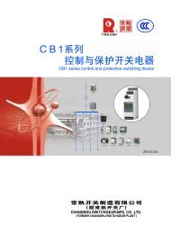
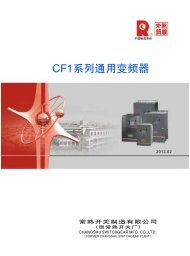
CW 1 系 列<br />
智 能 型 万 能 式 断 路 器<br />
CW1 SERIESINTELLIGENT AIR CIRCUITBREAKER<br />
CV 系 列<br />
CW 系 列<br />
CM 系 列<br />
CB 系 列 CK 系 列 CR 系 列 CA 系 列<br />
CJR 系 列 CJD 系 列 CD 系 列 CH 系 列 CE 系 列<br />
2013.10<br />
常 熟 开 关 制 造 有 限 公 司<br />
( 原 常 熟 开 关 厂 )<br />
CHANGSHU SWITCHGEARMFG.CO.,LTD.<br />
(FORMERCHANGSHUSWITCHGEARPLANT)
StateTorch Plan KeyHigh-tech<br />
Enterprise<br />
QualityManagement System Certificate<br />
Environmental Management<br />
System Certificate<br />
OccupationalHealthAndSafety<br />
ManagementSystem Certificate<br />
National Enterprise Technology Center<br />
China Well-known Trademark<br />
Certificate OfConformity For<br />
MeasurementManagement Systems<br />
National Innovative Pilot Enterprise<br />
Postdoctoral Programme
公 司 简 介<br />
Introduction<br />
常 熟 开 关 制 造 有 限 公 司 是 国 有 资 产 参 股 的 电 器 制 造 企 业 、“ 国 家 重 点 高 新 技 术 企<br />
业 ”, 占 地 约 300 亩 , 员 工 1685 人 。 主 要 生 产 中 低 压 电 器 元 件 、 工 控 产 品 、 太 阳 能 光 伏<br />
逆 变 器 、 成 套 装 置 等 , 可 以 为 您 提 供 “ 智 能 配 电 系 统 三 位 一 体 完 整 的 解 决 方 案 ”。<br />
公 司 建 有 博 士 后 科 研 工 作 站 、 国 家 认 定 企 业 技 术 中 心 和 江 苏 省 电 器 控 制 工 程 中<br />
心 , 具 有 一 支 以 博 士 、 硕 士 、 本 科 生 为 主 的 多 层 次 研 发 队 伍 , 工 程 技 术 人 员 占 企 业 员<br />
工 总 数 的 50% 左 右 。 公 司 拥 有 先 进 的 模 具 制 造 、 零 部 件 自 动 化 生 产 、 断 路 器 装 配 自 动<br />
检 测 流 水 线 等 一 大 批 先 进 的 制 造 和 试 验 检 测 设 备 ; 实 施 以 ERP 管 理 为 重 点 的 信 息 化 、<br />
网 络 化 管 理 ; 完 善 质 量 / 环 境 / 职 业 健 康 安 全 体 系 , 确 保 为 用 户 提 供 优 质 、 安 全 、 可<br />
靠 的 产 品 。CM 系 列 塑 料 外 壳 式 断 路 器 、CW 系 列 智 能 型 万 能 式 断 路 器 曾 双 双 被 评 为 中<br />
国 名 牌 产 品 。<br />
Changshu Switchgear Mfg. Co., Ltd. (Former Changshu Switchgear Plant), an enterprise with stateowned<br />
equity, covered an area of 200,000 m, with 1685 staffs, is a "National Key New High-tech<br />
2<br />
Enterprise" and mainly produces HV and LV electrical components, industry control products, solar<br />
photovoltaic inverters and complete sets of equipment etc, all of which could provide trinity and<br />
complete solutions for intelligent power distribution system.<br />
Post - doctoral scientific research station, Province Enterprise Technique Center and Jiangsu<br />
Province Electrical Apparatus Control Engineering Research Center have been established and a multilevel<br />
professional technique team has been formed consisting of PHD candidates, postgraduates and<br />
university graduates. Engineers and technicians have covered 50% of all staffs.<br />
Advanced mould manufacturing equipments, automation producing equipments for spare parts, assembling<br />
and inspecting lines for breakers and test equipments have been brought in. Meanwhile, information and<br />
network management, taking ERP management as the focal point, has been applied and quality environmental<br />
systems (ISO9001/ISO14001/OHSMS18001) have also been established and perfected to ensure reliability and<br />
safety for customers.<br />
CM Series Moulded Case Circuit Breaker and CW Series Intelligent Air Circuit Breaker are both China<br />
Top Brand products.
常 熟 开 关 制 造 有 限 公 司<br />
为 您 提 供 电 气 系 统 完 整 的 解 决 方 案<br />
CV1-12 系 列<br />
高 压 真 空 断 路 器<br />
CV2-12 系 列<br />
高 压 真 空 断 路 器<br />
CV1-24 系 列<br />
高 压 真 空 断 路 器<br />
CV1-40.5 系 列<br />
高 压 真 空 断 路 器<br />
CW1 系 列<br />
智 能 型 万 能 式 断 路 器<br />
CW2 系 列<br />
智 能 型 万 能 式 断 路 器<br />
CW3 系 列<br />
智 能 型 万 能 式 断 路 器<br />
CW3V 系 列<br />
智 能 型 真 空 万 能 式 断 路 器<br />
CM1 系 列<br />
塑 料 外 壳 式 断 路 器<br />
CM1 E系 列<br />
电 子 式 塑 壳 断 路 器<br />
CM1 Z系 列<br />
智 能 型 可 通 信 塑 壳 断 路 器<br />
CM1 L系 列<br />
带 剩 余 电 流 保 护 塑 壳 断 路 器<br />
CM1 EL系 列<br />
带 剩 余 电 流 保 护<br />
电 子 式 塑 壳 断 路 器<br />
CM2 系 列<br />
塑 料 外 壳 式 断 路 器<br />
CM2Z 系 列<br />
智 能 型 塑 壳 断 路 器<br />
CM2L 系 列<br />
带 剩 余 电 流 保 护 塑 壳 断 路 器<br />
CM3 系 列<br />
塑 料 外 壳 式 断 路 器<br />
CM3E 系 列<br />
电 子 式 塑 壳 断 路 器<br />
CM3L 系 列<br />
带 剩 余 电 流 保 护 塑 壳 断 路 器<br />
CM5 系 列<br />
塑 料 外 壳 式 断 路 器<br />
CM5Z 系 列<br />
智 能 型 塑 壳 断 路 器<br />
CM5L 系 列<br />
带 剩 余 电 流 保 护 塑 壳 断 路 器<br />
CM5ZL 系 列<br />
带 剩 余 电 流 保 护 智 能 型 塑 壳 断 路 器<br />
CM5Z/iP 系 列<br />
能 量 监 测 型 智 能 塑 壳 断 路 器<br />
CM5G 系 列<br />
隔 离 开 关
常 熟 开 关 制 造 有 限 公 司<br />
为 您 提 供 电 气 系 统 完 整 的 解 决 方 案<br />
CA1/CA1B 系 列 自 动<br />
转 换 开 关 (CB 级 )<br />
CAP1 系 列 自 动<br />
转 换 开 关 (PC 级 )<br />
CAP2 系 列 自 动<br />
转 换 开 关 (PC 级 )<br />
CK3 系 列 接 触 器<br />
CJR3 系 列<br />
热 过 载 继 电 器<br />
CJD3 系 列<br />
电 子 过 载 继 电 器<br />
CLJ3 剩 余 电 流<br />
动 作 继 电 器<br />
CR1 系 列<br />
电 动 机 软 起 动 器<br />
CR2 系 列<br />
智 能 型 电 动 机 软 起 动 器<br />
CD4 系 列<br />
智 能 马 达 保 护 器<br />
CB1 系 列<br />
控 制 和 保 护 开 关 电 器 (CPS)<br />
CF1 系 列<br />
变 频 器<br />
CS1G 系 列 三 相 并 网 型<br />
光 伏 发 电 逆 变 器<br />
CW3G 系 列 CW3DC 系 列<br />
隔 离 开 关 (AC,DC) 直 流 万 能 式 断 路 器<br />
CM3DC 系 列<br />
直 流 塑 壳 断 路 器<br />
CH 系 列 小 型 断 路 器<br />
CE1 系 列<br />
智 能 型 电 力 仪 表<br />
CI1 系 列<br />
远 程 智 能 I/O 模 块<br />
CN1DP-MP<br />
CN1DP-MD<br />
CN1DP-MC<br />
通 信 适 配 器<br />
CN1EG 以 太 网<br />
适 配 器<br />
FDM3<br />
短 消 息 通 知 模 块<br />
FWB1 温 度 报 警 模 块<br />
●Riyear-PowerNet 配 电 监 控 系 统<br />
●FCX3 智 能 配 电 监 控 器
优 秀 特 色<br />
通 过 核 工 业 条 件 (1E 级 ) 试 验 和 船 用 条 件 的 试 验 , 可 陆 用 、 船 用 、<br />
核 级 用 、 风 电 用 ( 低 温 -40℃、 湿 热 带 TH 型 )<br />
通 过 了 德 国 莱 茵 公 司 CE 认 证<br />
获 得 国 际 认 可 的 CB 证 书<br />
智 能 化 、 零 飞 弧 、 带 隔 离 功 能<br />
较 高 的 分 断 和 短 时 耐 受 能 力<br />
额 定 极 限 短 路 分 断 能 力 :Icu:400V:80kA~120kA:690V:50kA~75kA<br />
额 定 运 行 短 路 分 断 能 力 :Ics:400V:50kA~100kA:690V:50kA~65kA<br />
额 定 短 时 耐 受 电 流 Icw(1s):400V:50kA~100kA:690V:40kA~65kA<br />
具 有 过 载 长 延 时 、 短 路 短 延 时 、 短 路 瞬 时 及 接 地 故 障 保 护 功 能 , 保 护 丰 富 : 可 用 于 配 电<br />
线 路 保 护 , 马 达 保 护 、 变 压 器 和 母 线 保 护<br />
抽 屉 座 有 “ 连 接 ”、“ 试 验 ”、“ 分 离 ” 三 个 位 置 指 示<br />
基 于 Modbus-RTU 协 议 的 通 信 断 路 器 , 通 过 本 公 司 的 CN1DP 适 配 器 、CN1EG 以 太 网 适 配<br />
器 可 应 用 于 Modbus、Profibus、Devicenet、CAN 总 线 和 以 太 网 通 信 网 络 , 方 便 用 户 进 行 多<br />
种 协 议 的 应 用 管 理<br />
通 过 配 置 FDM3 短 消 息 通 知 模 块 , 可 实 现 断 路 器 故 障 脱 扣 或 报 警 信 息 无 线 监 视<br />
可 配 FWB1 温 度 报 警 模 块 , 实 现 连 接 点 在 线 超 温 报 警
目 录<br />
概<br />
述<br />
1<br />
结 构 简 介<br />
主 要 技 术 指 标<br />
断 路 器 功 耗 及 降 容 系 数<br />
高 海 拔 降 容<br />
智 能 控 制 器 特 性<br />
接 地 故 障 保 护 电 路<br />
电 气 附 件<br />
3<br />
10<br />
11<br />
11<br />
12<br />
25<br />
26<br />
机 械 附 件<br />
30<br />
自 动 电 源 转 换 系 统<br />
断 路 器 外 形 尺 寸 及 安 装 尺 寸<br />
断 路 器 门 框 开 孔 尺 寸<br />
34<br />
38<br />
47<br />
附 件 外 形 安 装 尺 寸<br />
51<br />
安 装 使 用<br />
断 路 器 安 装 安 全 间 隙<br />
自 动 电 源 转 换 系 统 外 形 尺 寸 及 安 装 尺 寸<br />
51<br />
52<br />
53<br />
断 路 器 二 次 回 路 接 线 图<br />
54<br />
自 动 电 源 转 换 系 统 电 气 线 路 图<br />
断 路 器 二 次 接 线 典 型 方 案 举 例<br />
组 网 与 监 控<br />
65<br />
69<br />
71<br />
FWB1 温 度 报 警 模 块<br />
79<br />
断 路 器 订 货 规 范<br />
通 信 可 选 元 件 及 温 度 报 警 模 块 订 货 规 范<br />
81<br />
86
概<br />
述<br />
CW1 系 列 智 能 型 万 能 式 断 路 器 用 于 控 制 和 保<br />
护 低 压 配 电 网 络 。 一 般 安 装 在 低 压 配 电 柜 中 作 主<br />
开 关 起 总 保 护 作 用 。 额 定 电 流 1000A 及 以 下 的 断<br />
路 器 , 还 可 作 电 动 机 保 护 用 。 产 品 可 提 供 湿 热 带<br />
型 (TH 型 )、 船 用 型 和 1E 级 断 路 器 , 可 提 供 低 温<br />
至 -40℃ 断 路 器 , 并 可 提 供 液 晶 显 示 及 数 码 管 显 示<br />
断 路 器 。<br />
交 流 额 定 电 流 630A~5000A;<br />
短 路 分 断 能 力 80kA~120kA( 有 效 值 );<br />
额 定 工 作 电 压 AC50Hz/60Hz, 690V 及 以 下<br />
( 不 适 用 于 690V IT 系 统 );<br />
使 用 类 别 B;<br />
具 有 3 极 和 4 极 ;<br />
抽 屉 式 和 固 定 式 ;<br />
可 倒 进 线 安 装 ;<br />
多 种 智 能 控 制 器 , 提 供 不 同 功 能 ;<br />
具 有 隔 离 功 能 , 符 号 为<br />
“ ”;<br />
执 行 IEC60947-2、GB14048.2-2008 标 准 ;<br />
本 断 路 器 获 国 家 强 制 性 产 品 认 证 “CCC” 标<br />
志 。<br />
CW1 series intelligent air circuit breakers could be<br />
used for controlling the low voltage distribution net and<br />
keeping it safety.Installing in the low voltage distribution<br />
panels,it works as master switch to play general safety<br />
role.The circuit breaker,with rated current 1000A and<br />
below,can alsoprotectesnotor.The breaker can be provided<br />
for humid type、<br />
forshiptypeand1Eclass,maybeprovided<br />
breaker of temperature downto -40 ℃ ,also can be provided<br />
LCDdisplayedtypeandLEDdisplayedtype.<br />
Ratedcurrent630A~5000AAC;<br />
Short circuit Breaking Capacity 80kA~<br />
120kA(effectivevalue);<br />
Rated working voltage 690V AC50Hz/60Hz or<br />
below(ben'tsuit for690V IT system);<br />
UtilizationcategoryB;<br />
Threeorfourpoles;<br />
Draw-outorFixedType;<br />
Canbeinadversedirection;<br />
Varied Intelligent controller offering various<br />
function;<br />
The breaker has disconnecting function,its<br />
correspondingsymbolisshownas “ ”;<br />
Comply with the demands of the following<br />
standards,IEC60947-2、 GB14048.2-2008;<br />
Thebreaker is permitted to use theCCC markingof<br />
CQC.<br />
型 号 含 义<br />
Typeand ItsMeaning<br />
CW1 /<br />
常 熟 开 关 制 造 有 限 公 司<br />
( 原 常 熟 开 关 厂 )<br />
Changshu SwitchgearMfg. Co.,Ltd.<br />
( FormerChangshu Switchgear Plant)<br />
极 数 ( 三 极 不 写 出 )<br />
Poles(omitfor three poles)<br />
万 能 式 断 路 器<br />
UniversalBreakers<br />
设 计 代 号<br />
Designcode<br />
断 路 器 框 架 等 级 额 定 电 流<br />
Rated currentofframe<br />
31
概<br />
述<br />
正 常 工 作 条 件 和 安 装 条 件<br />
Environment Conditions For Operation And Installation<br />
断 路 器 可 在 周 围 空 气 温 度 为 -5℃~+40℃ 条<br />
件 下 运 行 ( 大 于 +40℃ 至 +60℃ 见 P12 断 路 器 降 容<br />
系 数 );<br />
安 装 地 点 的 海 拔 不 超 过 2000m;<br />
安 装 地 点 的 空 气 相 对 湿 度 在 最 高 温 度 为<br />
+40℃ 时 不 超 过 50%; 在 较 低 温 度 下 可 以 有 较 高 的<br />
相 对 湿 度 , 例 如 20℃ 时 达 90%, 对 由 于 温 度 变 化<br />
偶 尔 产 生 的 凝 露 , 应 采 取 特 殊 的 措 施 ;<br />
污 染 等 级 为 3 级 ;<br />
断 路 器 主 电 路 及 欠 电 压 脱 扣 器 线 圈 、 电 源 变<br />
压 器 初 级 线 圈 的 安 装 类 别 为 Ⅳ, 其 余 辅 助 电 路 、<br />
控 制 电 路 安 装 类 别 为 Ⅲ;<br />
断 路 器 适 用 于 电 磁 环 境 A;<br />
断 路 器 应 按 使 用 说 明 书 安 装 要 求 安 装 。 断 路<br />
器 的 垂 直 倾 斜 度 不 超 过 5°, 船 用 断 路 器 不 超 过<br />
22.5°;<br />
断 路 器 应 安 装 在 无 爆 炸 危 险 和 无 导 电 尘 埃 、<br />
无 足 以 腐 蚀 金 属 和 破 坏 绝 缘 的 地 方 ;<br />
断 路 器 安 装 在 柜 体 小 室 内 , 且 加 装 门 框 , 防<br />
护 等 级 达 IP40。<br />
Ambient temperature: -5 ℃ ~ +40℃ ( If the<br />
tempera-ture is between +40℃ and +60 ℃ ,please see "<br />
the circuit breaker capacity lower coefficient" in page<br />
12 ).<br />
Elevationofinstallationsite:≤2000m.<br />
Relative humidity:<br />
not exceeding 50% at the<br />
maximum ambient temperature of +40 ℃ .With lower<br />
temperature, higher humidity would be permitted,but<br />
the lowestaveragetemperaturein amonthnotexceeding<br />
+25℃<br />
during the most moist moth, and the maximum<br />
monthly averagerelative humidity not exceeding 90% in<br />
thatmonth, andgiving consideration tothe dews onthe<br />
goods surface, which would appear dueto temperature<br />
change.<br />
Pollutionprotection:3grade.<br />
Installing categories: Ⅳ for breakers' main<br />
circuits, coils of under voltage release and primary<br />
circuit of transformers; Ⅲ for other auxiliarycircuits<br />
andcontrolcircuit.<br />
The breaker is suitable in electromagnetic<br />
environmentA.<br />
The breaker should be installed according to<br />
stipulations in operation manual. For breakers in<br />
common use, the vertical gradient isn't more than 5<br />
° ,forthatusedonships,theverticalgradientisn't more<br />
than22.5 ° .<br />
The breaker should be put in the place where<br />
there isn't any explosive medium and conductive dust<br />
and no gas which would corrode metal or distroythe<br />
insulation.<br />
Thebreaker should be installed in compartment<br />
of switch- board and door frame should be fixed<br />
additionally.ProtectiongradeisuptoIp40.<br />
32
结 构 简 介<br />
断 路 器 正 面 指 示<br />
Front View of the Circuit Breaker<br />
故 障 跳 闸 指 示 / 复 位 按 钮<br />
breakdownshowing/returnbutton<br />
分 闸 按 钮<br />
breaking button<br />
手 动 贮 能 手 柄<br />
handleformanualenergy-storage<br />
合 闸 按 钮<br />
closing buttom<br />
贮 能 释 能 指 示<br />
energystorage/energy releaseindicating<br />
合 闸 分 闸 指 示<br />
closed/brokenshowing<br />
面 板<br />
face<br />
手 柄 及 其 存 放 处<br />
handleandits holder<br />
位 置 指 示<br />
position indicator<br />
进 出 装 置<br />
devicefor passingin orout<br />
CW1 系 列 智 能 型 万 能 式 断 路 器<br />
CW1 Series Intelligent Universal Circuit Breaker<br />
CW1-5000<br />
CW1-4000 CW1-3200 CW1-2000<br />
3
结 构 简 介<br />
1<br />
2<br />
5<br />
6<br />
7<br />
11<br />
8<br />
9<br />
3<br />
10<br />
抽 屉 式 断 路 器<br />
1. 二 次 回 路 接 线 端 子 ( 静 )<br />
2. 抽 屉 座<br />
3. 安 全 隔 板<br />
4. 手 柄<br />
5. 二 次 回 路 接 线 端 子 ( 动 )<br />
6. 辅 助 开 关<br />
7. 欠 电 压 脱 扣 器<br />
8. 分 励 脱 扣 器<br />
9. 合 闸 电 磁 铁<br />
10. 操 作 机 构<br />
11. 电 动 操 作 机 构<br />
12. 智 能 控 制 器<br />
13. 面 板<br />
4<br />
12 13<br />
Draw-out circuit breaker<br />
1. Terminals ofsecondary circuit (fixed)<br />
2. Drawer base<br />
3. Safety separator<br />
4. Handle<br />
5. Terminals ofsecondary circuit (motional)<br />
6. Auxiliary switch<br />
7. Under-voltage release<br />
8. Shunt release<br />
9. Closing electromagnet<br />
10. Operation mechanism<br />
11. Motor-drive charging device<br />
12. Intelligent controller<br />
13. Panel<br />
4
结 构 简 介<br />
结 构 特 点<br />
断 路 器 有 固 定 式 和 抽 屉 式 之 分 , 把 固 定<br />
式 断 路 器 本 体 装 入 专 用 的 抽 屉 座 就 成 为<br />
抽 屉 式 断 路 器 。 断 路 器 本 体 由 触 头 系<br />
统 、 灭 弧 系 统 、 操 动 机 构 、 电 流 互 感<br />
器 、 智 能 控 制 器 和 辅 助 开 关 、 二 次 插 接<br />
件 、 欠 压 、 分 励 脱 扣 器 等 部 件 组 成 ; 抽<br />
屉 座 由 带 有 导 轨 的 左 右 侧 板 、 底 座 和 横<br />
梁 等 组 成 。<br />
触 头 系 统<br />
采 用 一 挡 触 头 系 统 , 在 同 一 触 头 的 不<br />
同 部 位 , 触 头 单 元 既 具 有 主 触 头 的 功<br />
能 , 也 具 有 弧 触 头 的 功 能 ;<br />
采 用 新 型 耐 弧 的 触 头 材 料 , 使 触 头 在<br />
分 断 短 路 电 流 后 不 致 过 分 发 热 而 引 起 温<br />
升 过 高 ;<br />
触 头 系 统 采 用 多 路 并 联 , 降 低 电 动 斥<br />
力 , 提 高 触 头 系 统 的 电 动 稳 定 性 。<br />
灭 弧 室<br />
每 个 极 均 设 有 一 个 灭 弧 室 , 其 作 用 是<br />
将 各 电 极 分 隔 开 , 并 相 互 绝 缘 , 与 断 路<br />
器 的 其 它 部 分 及 操 作 人 员 相 隔 离 ;<br />
灭 弧 室 全 部 置 于 断 路 器 的 绝 缘 底 座<br />
内 , 增 加 了 灭 弧 室 壁 的 机 械 强 度 , 不 致<br />
在 分 断 大 短 路 电 流 时 炸 裂 。<br />
操 作 机 构 和 手 动 、 电 动 传 动 机 构<br />
机 构 位 于 断 路 器 正 面 。 操 动 机 构 采 用 五<br />
连 杆 的 自 由 脱 扣 机 构 , 并 设 计 成 贮 能 形<br />
式 。 在 使 用 过 程 中 , 机 构 总 是 处 于 预 贮<br />
能 位 置 , 只 要 断 路 器 一 接 到 合 闸 命 令 ,<br />
断 路 器 就 能 立 即 瞬 时 闭 合 。 预 贮 能 的 释<br />
放 可 用 手 动 释 能 按 钮 或 合 闸 电 磁 铁 来 完<br />
成 。 电 动 传 动 机 构 自 成 一 体 , 贮 能 轴 与<br />
主 轴 之 间 通 过 凹 凸 形 楔 口 活 动 联 结 , 装<br />
拆 方 便 。<br />
智 能 控 制 器<br />
智 能 控 制 器 的 方 框 图 如 图<br />
Structure Feature<br />
The breakers could be classified two types:fixed<br />
type and draw-out type.It would become the draw-out<br />
type breaker to putthe body of afixed type breaker into<br />
the special draw-out socket.The body of breaker consists<br />
of contacts system、 arc extiguish system、<br />
operating<br />
device、 transformer、<br />
intelligent controller and auxiliary<br />
switch、 secondaryplug and socket units、<br />
undervoltage<br />
andshunt release.Thedraw-outsocket ismadeup of :the<br />
rightside plate and leftside plate (with guidway) 、 base<br />
andcrossmember.<br />
Contactssystem<br />
One-gear system.The different part of the same<br />
contact is of the different function.The contacts unit is<br />
withbothmaincontactfunctionandarc-contactfunction;<br />
The new-type arc-resistant material is to be<br />
chosen for making contacts.After breaking the shortcircuit<br />
current,the contactswouldn't beoverheat tomake<br />
thetemperatureoverrising;<br />
The contacts system is made of the multiple way<br />
parallel style,to reduce the electric repulsion and to rise<br />
theelectricsteadyability.<br />
Arc-extiguishchamber<br />
There is aarc-extiguish chamber for each pole,to<br />
playtherole ofseperatingallthepoles and isolatingthem<br />
for eachother,and keepingit apartwithother partsof the<br />
breakerand operatingworker;<br />
The arc-extinguish chamber is all in the<br />
insulation base,to increase the mechanicalstrenth and<br />
would not to be crashed when breaking big short-circuit<br />
current.<br />
Operating device and manual、<br />
motor-driven<br />
transmitting device.The device is sitedon the frontof the<br />
breaker.The free-release device,with five connecting<br />
rods,is used in the operating device,and it is designed<br />
energy-storage form.The device is always on energystorage<br />
position,the breaker would be closed<br />
instantaneously as soon as thebreaker is ordered to be<br />
closed.To release the pre-stored energy,it may be by<br />
means of pushing the release energy button manually or<br />
using the closing electro-magnet.The motor-driven<br />
transmitting devicehave thesystemofitsown,linkingthe<br />
energy-storage shaft and main shaft movably with tenon<br />
andmortise,easily toassembleordisassemble.<br />
Intelligentcontroller<br />
Theschemeof intelligentcontroller<br />
信 号<br />
互 感<br />
器<br />
饱 和<br />
铁 心<br />
互 感<br />
器<br />
环 境 温<br />
度 检 测<br />
多 路 开 关<br />
及 放 大 器<br />
~220V 输 入<br />
辅 助<br />
电 源<br />
稳 压<br />
电 源<br />
CPU<br />
数 据 断<br />
电 保 护<br />
功 率<br />
放 大<br />
显 示 器<br />
整 定<br />
键 盘<br />
脱 扣 讯<br />
号 输 出<br />
通 讯<br />
接 口<br />
故 障 检<br />
测 输 出<br />
执 行<br />
元 件<br />
模 拟 脱<br />
扣 信 号<br />
signal<br />
transformer<br />
saturable<br />
transformer<br />
environment<br />
temperature<br />
inspection<br />
mulitiline<br />
switch and<br />
amplifier<br />
~220V input<br />
auxiliary<br />
supply<br />
voltagestabilized<br />
supply<br />
CPU<br />
data power<br />
failure<br />
protection<br />
power<br />
amplifier<br />
indicator<br />
setting<br />
keyboard<br />
release<br />
signal<br />
output<br />
communication<br />
interface<br />
fault<br />
detection<br />
output<br />
Execution<br />
unit<br />
Analogue<br />
release<br />
signal<br />
5
结 构 简 介<br />
抽 屉 座<br />
抽 屉 座 由 带 有 导 轨 的 左 右 侧 板 、 底 座<br />
和 横 梁 等 组 成 , 底 座 上 设 有 推 进 机 构 ,<br />
并 装 有 位 置 指 示 , 抽 屉 座 的 上 方 装 有 辅<br />
助 电 路 静 隔 离 触 头 。 桥 式 主 回 路 触 头 前<br />
方 设 置 安 全 隔 板 。<br />
断 路 器 本 体 在 抽 屉 座 内 的 运 动 具 有 三<br />
个 “ 位 置 ”:<br />
“ 连 接 ” 位 置 : 主 回 路 和 辅 助 回 路 均<br />
接 通 , 此 时 隔 离 板 开 启 ;<br />
Draw-out socket<br />
Thedraw-outsocketismadeupoftherightsideand<br />
leftside plates (with guided way),base and cross<br />
member.Thereare pushingdeviceand positionindicator on<br />
the base.There are static seperated contacts for auxiliary<br />
circuit onthe top ofthe base.The safetyseperator is set on<br />
thefrontofthebridgemaincontacts.<br />
Ithas three "position"forbreakerbodymovinginthe<br />
draw-outsocket:<br />
"link"position:thereare all"ON"formaincircuitand<br />
auxiliarycircuit.Theseperatorisopen;<br />
单 元 室 门<br />
辅 助 回 路 接 通<br />
抽 屉 座 后 部<br />
unitdoor<br />
auxiliarycircuitisON<br />
backof the draw-out socket<br />
安 全 隔 板<br />
safety seperator<br />
主 回 路 接 通<br />
main circuitis ON<br />
“ 试 验 ” 位 置 : 主 回 路 断 开 , 安 全 隔<br />
板 关 闭 , 仅 辅 助 回 路 接 通 , 可 进 行 必 要<br />
的 动 作 试 验 ;<br />
"test" position:The main circuit is "OFF",safety<br />
seperator is closed.Only auxiliary circuit is "ON",the<br />
necessaryactiontestcouldbe done;<br />
单 元 室 门<br />
辅 助 回 路 接 通<br />
抽 屉 座 后 部<br />
unitdoor<br />
auxiliarycircuitis ON<br />
backof thedraw-out socket<br />
安 全 隔 板<br />
safety seperator<br />
主 回 路 断 开<br />
main circuitis OFF<br />
“ 分 离 ” 位 置 : 主 回 路 与 辅 助 回 路 全<br />
部 断 开 , 安 全 隔 板 关 闭 。<br />
"seperated" position:The main circuit and<br />
auxiliarycircuitareall"OFF",safetyseperatorisclosed.<br />
单 元 室 门<br />
辅 助 回 路 断 开<br />
抽 屉 座 后 部<br />
unitdoor<br />
auxiliarycircuitis OFF<br />
backof thedraw-outsocket<br />
安 全 隔 板<br />
safety seperator<br />
主 回 路 断 开<br />
main circuitis OFF<br />
6
结 构 简 介<br />
智 能 控 制 器 的 选 择<br />
Selecting the intelligent controller<br />
智 能 控 制 器 按 功 能 分 有 三 种 类 型 :<br />
L型 -电 子 型 ( 电 流 柱 状 显 示 , 拨 盘 调 整 ),<br />
M型 -标 准 型 ( 电 流 数 字 显 示 , 按 钮 调 整 ),<br />
H型 -通 信 型 ( 电 流 数 字 显 示 , 按 钮 调 整 并 可<br />
通 信 )。<br />
MY型 -液 晶 显 示 标 准 型 ( 电 流 液 晶 显 字 , 按 钮 调 整 )<br />
HY型 -液 晶 显 示 通 信 型 ( 电 流 液 晶 显 字 , 按<br />
钮 调 整 并 可 通 信 )<br />
L 型 ( 电 子 型 )<br />
Type L(Electronic)<br />
Itcanbedividedintothreetypesaccordingtoits function:<br />
Type L,electronic type (current is indicated in columnar<br />
order,adjustedwithknob),<br />
TypeM, normal type (digital indication for current,can be<br />
adjustedwithpushbutton.)<br />
Type H,communicative type ( digital indication for<br />
current,can be adjusted with push button and be<br />
communicative.)<br />
Type MY,LCD displayed normal type(LCD indication for<br />
current,canbeadjustedwithpushbutton.)<br />
Type HY,LCD displayed communicative type(LCD<br />
indication for current,can be adjusted with push button<br />
and becommunicative.)<br />
复 位<br />
1<br />
16<br />
15<br />
14<br />
13<br />
12<br />
11<br />
S<br />
90%<br />
50%<br />
20%<br />
90<br />
I 1 I 2 I 3 IN<br />
105<br />
%Ir1<br />
报 警 及 脱 扣 指 示<br />
Ir 1 Ir 2<br />
Ir 3<br />
CW1- /4<br />
L 型 智 能 控 制 器<br />
3<br />
In=<br />
Ir 1<br />
t 1<br />
80 85 90 60 120<br />
75 95<br />
240<br />
30<br />
70<br />
15<br />
65 1<br />
480<br />
XIn<br />
s<br />
Ir 2 t 2<br />
5<br />
4 6<br />
3 8<br />
2<br />
Ir 3<br />
1.5<br />
3<br />
4 4 3<br />
2<br />
S<br />
2<br />
10 1 1<br />
XIr 1<br />
12 15 18<br />
10<br />
20<br />
8<br />
5 off<br />
XIr 1<br />
A<br />
45%<br />
25%<br />
15%<br />
5 8 10<br />
15<br />
ON<br />
I 2 t<br />
OFF<br />
2<br />
3<br />
4<br />
5<br />
6<br />
7<br />
8<br />
9<br />
10<br />
面 板 说 明 :<br />
Panel caption:<br />
1.<br />
2.<br />
3.<br />
故 障 脱 扣 复 位 按 钮<br />
光 柱 显 示 负 载 率 (%Ir 1)<br />
断 路 器 额 定 电 流<br />
1. returnbutton for fault releasing<br />
2. load indication in percentage(%Ir 1)<br />
3. rated current of the breaker<br />
4.<br />
5.<br />
6.<br />
7.<br />
8.<br />
9.<br />
10.<br />
11.<br />
12.<br />
13.<br />
14.<br />
15.<br />
16.<br />
长 延 时 电 流 调 节<br />
长 延 时 时 间 调 节<br />
短 延 时 电 流 调 节<br />
短 延 时 时 间 调 节<br />
瞬 动 电 流 调 节<br />
试 验 电 流 调 节<br />
测 试 端 ( 制 造 厂 测 试 检 查 用 )<br />
“ 清 灯 ” 键<br />
试 验 按 钮<br />
长 延 时 故 障 指 示<br />
短 延 时 故 障 指 示<br />
瞬 时 故 障 指 示<br />
报 警 及 脱 扣 指 示<br />
4. long-delay currentsetting<br />
5. long-delay time setting<br />
6. short-delay current setting<br />
7. short-delay time setting<br />
8. instantaneous action current<br />
setting<br />
9. test current setting<br />
10. test terminal (for the purpose of<br />
inspection by the manufacturer)<br />
11. "clean" key<br />
12. test key<br />
13. fault showing for long-delay<br />
14. fault showing for short-delay<br />
15. fault showing for instantaneous<br />
16. alarm and release showing<br />
其 它 功 能 :<br />
Otherfunction:<br />
1.<br />
2.<br />
热 模 拟 功 能<br />
MCR 功 能<br />
1. thermo-memory<br />
2. MCR function<br />
1.5<br />
1<br />
XIn<br />
清 灯 试 验 测 试<br />
注 : 图 示 L型 智 能 控 制 器 面 板 表 示 断 路 器 极 数 为 四 极 , 且 N极 过 电 流 保 护 为 相 极 的 50%; 当 断 路 器 N极 过 电 流 保 护 为 相 极<br />
的 100% 时 , N极 光 柱 右 侧 负 载 指 示 百 分 值 ( 20%、 50% 及 90%) 因 与 相 极 相 同 而 不 再 另 外 表 示 ; 当 断 路 器 为 三<br />
极 时 , 无 IN光 柱 显 示 。<br />
Note:Thepanelhereinbelongsto thecircuitbreakerof fourpoles,in which the over-currentprotectionvalueinNpole is<br />
50%thatofineachphase.In case theformeris100%ofthelater,the percentage value indication (20%,50% and<br />
90%) of loadingcurrent totherightofcolumn square will disappear.There isno indication of"I N"columnsqure in<br />
case ofthree phasebreaker.<br />
7
结 构 简 介<br />
智 能 控 制 器 的 选 择<br />
Selecting the intelligent controller<br />
M 型 ( 标 准 型 )Type M(Normal) MY 型 ( 液 晶 显 示 标 准 型 )Type MY (LCD displayed normal tpe)<br />
1<br />
1<br />
复<br />
位<br />
CW1- /4<br />
M 型 智 能 控 制 器<br />
In=<br />
2<br />
3<br />
复<br />
位<br />
CW1- /4<br />
MY 型 智 能 控 制 器<br />
In=<br />
2<br />
5<br />
6<br />
7<br />
V<br />
4<br />
U12 U23 U31 MIN 选 择 2<br />
36<br />
35<br />
34<br />
33<br />
32<br />
31<br />
30<br />
脱<br />
扣<br />
U 12 U 23 U 31<br />
选 择 2<br />
A<br />
试 验 I N I G I 1 I 2 I 3 MAX 选 择 1<br />
S<br />
t<br />
1<br />
t2<br />
t4<br />
面 板 说 明 :<br />
1. 故 障 脱 扣 复 位 按 钮<br />
2. 断 路 器 额 定 电 流<br />
3. 电 压 单 位<br />
4. 电 压 显 示 屏<br />
5. 三 相 线 电 压 及 最 小 值 指 示<br />
6. 电 压 选 择 键<br />
7. 电 流 、 时 间 显 示 屏 ( M型 ), 电<br />
压 、 电 流 时 间 显 示 屏 ( MY型 )<br />
8. 电 流 、 时 间 单 位<br />
9. 三 相 电 流 、 中 性 相 电 流 、 接 地 故<br />
障 电 流 及 最 大 值 指 示<br />
10. 电 流 及 时 间 选 择 键<br />
“ 清 灯 ” 键<br />
11.<br />
12.<br />
13.<br />
14.<br />
15.<br />
16.<br />
17.<br />
18.<br />
19.<br />
瞬 动 故 障 指 示<br />
短 路 短 延 时 故 障 指 示<br />
过 载 长 延 时 故 障 指 示<br />
接 地 故 障 指 示<br />
长 延 时 电 流 整 定 指 示 ( 兼 报 警 )<br />
长 延 时 动 作 时 间 整 定 指 示<br />
短 延 时 电 流 整 定 指 示 ( 兼 报 警 )<br />
短 延 时 动 作 时 间 整 定 指 示<br />
故 障<br />
MIN<br />
Ir4<br />
Ir1 Ir2 Ir3<br />
I<br />
A<br />
KA<br />
S<br />
清<br />
灯<br />
5<br />
6<br />
7<br />
8<br />
9<br />
10<br />
11<br />
12<br />
13<br />
14<br />
15<br />
16<br />
17<br />
18<br />
19<br />
20<br />
21<br />
设 定<br />
%<br />
22<br />
32<br />
ILC1 ILC2 故 障 检 查<br />
设 定 ILC1 ILC2 % 故 障 检 查<br />
23<br />
+ - 24<br />
+ -<br />
脱 扣 不 脱 扣 贮 存<br />
25<br />
脱 扣 不 脱 扣 贮 存<br />
26<br />
31<br />
测 试<br />
测 试<br />
试 验<br />
调 整<br />
30<br />
27<br />
试 验<br />
调 整<br />
29 28<br />
29 28<br />
20. 瞬 动 电 流 整 定 指 示 ( 兼 报 警 )<br />
21. 故 障 检 查 键<br />
22. 触 头 磨 损 检 查 按 钮<br />
23. 负 载 监 控 信 号 2 电 流 整 定 ( 兼 报 警 )<br />
24. 负 载 监 控 信 号 1 电 流 整 定 ( 兼 报 警 )<br />
25. 整 定 值 递 减<br />
26. 整 定 值 递 增<br />
27. 测 试 口 ( 制 造 厂 测 试 检 查 用 )<br />
28. 贮 存 键<br />
29. 贮 存 指 示<br />
30. 不 脱 扣 试 验 按 钮<br />
31. 脱 扣 试 验 按 钮<br />
32. 各 种 保 护 值 的 设 定 按 钮<br />
33. 接 地 故 障 动 作 时 间 整 定 指 示<br />
34. 接 地 故 障 电 流 整 定 指 示 ( 兼 报 警 )<br />
35. 脱 扣 指 示<br />
36. 试 验 指 示<br />
其 它 功 能 :<br />
1. 自 诊 断 功 能<br />
2. 热 模 拟 功 能<br />
3. 故 障 记 忆 功 能<br />
4. MCR 功 能<br />
注 : 图 示 M型 智 能 控 制 器 面 板 表 示 断 路 器 极 数 为 四 极 , 如 断 路 器 为 三 极 , 则 面 板 说 明 项 9无 中 性 相 电 流 IN; 另 外 , 本 厂 除 提 供 带 电 压<br />
显 示 功 能 的 M型 智 能 控 制 器 外 ( 图 示 ), 还 提 供 不 带 电 压 显 示 功 能 的 M型 智 能 控 制 器 ( 图 示 面 板 说 明 无 3、 4、 5、 6项 )。<br />
Note:The Panel herein belongs to the circuit breaker of four poles,If the breaker is of three poles,the mark “ IN” in item “ 9”<br />
indicating current of neutral phase will disappear.Other than the type Mintelligent controller with voltage indication,the other one<br />
without voltage indication is also available (there aren't items “ 3”、<br />
“ 4”、“ 5” and “ 6”<br />
onthe panel in this case.)<br />
8<br />
36<br />
35<br />
34<br />
33<br />
Panel caption:<br />
1. returnbutton forfault releasing<br />
2. ratedcurrent ofthebreaker<br />
3. unitofvoltage<br />
4. voltageindicator<br />
5. voltageofeachlineandthemin.value<br />
6. keyforselecting voltage<br />
7. current、<br />
timeindicator typeM<br />
voltage<br />
S<br />
t1<br />
t2<br />
timeindicator(type MY)<br />
8. unitofcurrent andtime<br />
9. indicationofthreephase current,ne-utral<br />
phase current,groundingfault-currentand<br />
themax.value<br />
10. keyforselecting current<br />
11. "clean"key<br />
12. faultshowingforinstantaneous<br />
13. faultshowingforshort-circuit short- delay<br />
14. faultshowingforover-load long-delay<br />
15. faultshowingforearthed error<br />
16. showingthe long-delaycurrentsetting<br />
(alarm simultaneously)<br />
17. showingthe long-delayactiontimesetting<br />
18. showingthe short-delay currentsetting<br />
(alarm simultaneously)<br />
19. showingthe short-delay actiontimesetting<br />
20. showingthe instantaneouscurrentsetting<br />
(alarm simultaneously)<br />
试 验 IN IG I1 I2 I3 MAX 选 择 1<br />
故 障<br />
t4<br />
Ir4 Ir1 Ir2 Ir3 A<br />
I<br />
21. keyforinspectingfault<br />
22. keyfordetectingwearingof contacts<br />
23. load supervisionsignal2(alarm simul<br />
taneously )<br />
24. load supervisionsignal1(alarm simul<br />
taneously )<br />
25. setting's decrease progressively<br />
26. setting's increase progressively<br />
27. testterminal (for the purpose of<br />
inspectionby themanufacturer)<br />
28. memory key<br />
29. memory indicator<br />
30. non-releasetestkey<br />
31. release testkey<br />
32. settingkeyforvariousprotection value<br />
33. indicationofthe earthedfault action<br />
time setting<br />
34. indicationof theearthedfault current<br />
setting (alarmsimultaneously)<br />
35. release indicating<br />
36. testindicating<br />
Otherfunction:<br />
1. auto-diagnosis<br />
2. thermo-memory<br />
3. fault-memory<br />
4. MCR<br />
9<br />
10<br />
11<br />
12<br />
13<br />
14<br />
15<br />
16<br />
17<br />
18<br />
19<br />
20<br />
21<br />
22<br />
23<br />
24<br />
25<br />
26<br />
27
结 构 简 介<br />
智 能 控 制 器 的 选 择<br />
Selecting the intelligent controller<br />
H 型 ( 通 信 型 ) Type H(Communicative) HY 型 ( 液 晶 显 示 通 信 型 )Type HY (LCD displayed commuicative type)<br />
1<br />
1<br />
2<br />
2<br />
复<br />
位<br />
CW1- /4<br />
H 型 智 能 控 制 器<br />
In=<br />
3<br />
复<br />
位<br />
CW1- /4<br />
HY 型 智 能 控 制 器<br />
In=<br />
39<br />
38<br />
37<br />
36<br />
脱<br />
扣<br />
U<br />
12 U 23 U 31 MIN<br />
试 验 I N I G I 1 I 2 I 3 MAX 选 择 1<br />
故 障<br />
I<br />
V<br />
选 择 2<br />
A<br />
kA<br />
s<br />
4<br />
5<br />
6<br />
7<br />
8<br />
9<br />
10<br />
11<br />
35<br />
12<br />
35<br />
s<br />
13<br />
S<br />
12<br />
14<br />
13<br />
t1<br />
15<br />
t1<br />
14<br />
16<br />
34 t2<br />
17<br />
34<br />
15<br />
t2<br />
16<br />
t4<br />
18<br />
t4<br />
19<br />
17<br />
33<br />
I r4 I r1<br />
I r2 I r 3 A<br />
20<br />
33<br />
18<br />
19<br />
21<br />
Ir4 Ir1 Ir2 Ir3 A<br />
20<br />
22<br />
21<br />
32<br />
设 定 ILC1 ILC2 % 故 障 检 查<br />
32<br />
设 定 ILC1 ILC2 % 故 障 检 查<br />
23<br />
22<br />
+ - 24<br />
+ -<br />
23<br />
脱 扣 不 脱 扣 贮 存<br />
25<br />
31<br />
26<br />
脱 扣 不 脱 扣 贮 存<br />
24<br />
31<br />
25<br />
测 试<br />
30<br />
试 验<br />
27<br />
测 试<br />
26<br />
调 整<br />
30<br />
试 验<br />
调 整<br />
29 28<br />
29 28<br />
27<br />
故 障 检 查 键<br />
Panel caption:<br />
setting(alarm simultaneously)<br />
面 板 说 明 :<br />
21.<br />
1. return button forfaultreleasing 21. keyforinspectingfault<br />
1. 故 障 脱 扣 复 位 按 钮<br />
22. 触 头 磨 损 检 查 按 钮<br />
2. ratedcurrent maximum(could be 22. keyfordetectingwearingof contacts<br />
2. 断 路 器 额 定 电 流<br />
23. 负 载 监 控 信 号 2 电 流 整 定 ( 兼 报 警 )<br />
protected)<br />
23. loading 2current setting(alarm<br />
3. 电 压 单 位<br />
24. 负 载 监 控 信 号 1 电 流 整 定 ( 兼 报 警 ) 3. voltage indicator<br />
simultaneously)<br />
4. unit ofvoltage indicating<br />
4. 电 压 显 示 屏<br />
整 定 值 递 减<br />
24. loading 1current setting(alarm<br />
25.<br />
5. voltage phaseandminimun<br />
simultaneously)<br />
5. 三 相 线 电 压 及 最 小 值 指 示<br />
26. 整 定 值 递 增<br />
6. keyforselecting voltage<br />
25. decreaseprogressively<br />
6. 电 压 选 择 键<br />
27. 测 试 口 ( 制 造 厂 测 试 检 查 用 )<br />
7. Current、 time、<br />
number indicator, 26. increase progressively<br />
7. 电 流 、 时 间 显 示 屏 H型 , 电 压 、 电 流 时 28. 贮 存 键<br />
voltage、 current、<br />
timeindicator(type HY) 27. testterminal (for the purpose of<br />
8. unit ofcurrent、<br />
timeindicating<br />
间 显 示 屏 ( HY型 )<br />
inspectionby themanufacturer)<br />
29. 贮 存 指 示<br />
9. indicatingthemaximunofcurrent 28. memory key<br />
8. 电 流 、 时 间 单 位<br />
30. 不 脱 扣 试 验 按 钮<br />
phase<br />
29. memory indicator<br />
9. 三 相 电 流 、 中 性 相 电 流 、 接 地 故 障 电 31. 脱 扣 试 验 按 钮<br />
10. keyforselecting current<br />
30. non-releasetestkey<br />
流 及 最 大 值 指 示<br />
32. 各 种 保 护 值 的 设 定 按 钮<br />
11. "clean" key<br />
31. release testkey<br />
12. faultshowingforinstantaneous 32. settingkeyforvariousprotection<br />
10. 电 流 及 时 间 选 择 键<br />
33. 接 地 故 障 动 作 时 间 整 定 指 示<br />
11. “ 清 灯 ” 键<br />
34. 接 地 故 障 电 流 整 定 指 示 ( 兼 报 警 )<br />
12. 瞬 动 故 障 指 示<br />
35. 脱 扣 指 示<br />
14. faultshowingforover-load long-delay setting<br />
13. 短 路 短 延 时 故 障 指 示<br />
试 验 指 示<br />
15. faultshowingforearthed error<br />
36.<br />
34. showing theearthedcurrent setting<br />
16. showing the long-delaycurrentsettshowing<br />
the long-delayactiontime 36. testindicating<br />
(alarm simultaneously)<br />
14. 过 载 长 延 时 故 障 指 示<br />
37. 遥 控<br />
ing(alarmsimultaneously)<br />
35. release indicating<br />
15. 接 地 故 障 指 示<br />
38. 站 号<br />
17.<br />
16. 长 延 时 电 流 整 定 指 示 ( 兼 报 警 ) 39. 通 信<br />
setting<br />
37. remote control<br />
17. 长 延 时 动 作 时 间 整 定 指 示 其 它 功 能 :<br />
18. showing the short-delaycurrentsetshowing<br />
the short-delayaction time Other function:<br />
38. serial number<br />
ting (alarmsimultaneously)<br />
39. communication<br />
18. 短 延 时 电 流 整 定 指 示 ( 兼 报 警 ) 1. 自 诊 断 功 能<br />
19.<br />
19. 短 延 时 动 作 时 间 整 定 指 示<br />
2. 热 模 拟 功 能<br />
1. auto-diagnosis<br />
setting<br />
2. thermo-memory<br />
20. 瞬 动 电 流 整 定 指 示 ( 兼 报 警 ) 3. 故 障 记 忆 功 能<br />
20. showing the instantaneous current<br />
3. fault-memory<br />
4. MCR 功 能<br />
4. MCR<br />
注 : 图 示 H型 智 能 控 制 器 面 板 表 示 断 路 器 极 数 为 四 极 , 如 断 路 器 为 三 极 , 则 面 板 说 明 项 9无 中 性 相 电 流 IN; H型 智 能 控 制 器 带 电 压 显 示 功 能 。<br />
Note:The panel herein belongs to the circuit breaker of four poles.If breaker is of three poles,the mark “ IN” in item “ 9”<br />
on the panel<br />
indicating current of neutral phase will disappear. Type Hintelligent controller is provided with voltage indication.<br />
13. faultshowingforshort-circuit short-<br />
value<br />
delay<br />
33. showing theearthedactiontime<br />
9<br />
39<br />
38<br />
37<br />
36<br />
通 信<br />
站 号<br />
遥 控<br />
U12 U23 U31 MIN 选 择 2<br />
试 验 IN I1 I2 I3 MAX 选 择 1<br />
IG<br />
故 障<br />
I<br />
5<br />
6<br />
7<br />
9<br />
10<br />
11
主 要 技 术 指 标<br />
型 号 Type<br />
框 架 等 级 额 定 电 流 Inm (A) Frame Rated Current Inm (A)<br />
额 定 电 流 In(A) Rated Current In (A)<br />
CW1-2000 1)<br />
2000<br />
CW1-3200<br />
3200<br />
CW1-4000<br />
4000<br />
CW1-5000<br />
5000<br />
630、 800、<br />
2000、 2500、<br />
3200、 3600、 1000、 1250、<br />
4000、<br />
5000<br />
2900、<br />
3200 4000<br />
1600、<br />
2000<br />
额 定 工 作 电 压 Ue(V)<br />
额 定 绝 缘 电 压 Ui(V)<br />
额 定 冲 击 耐 受 电 压 Uimp (kV)<br />
工 频 耐 受 电 压 U<br />
极 数<br />
智 能 控 制 器<br />
Quantity ofpoles<br />
Intelligent Controller<br />
电 气 寿 命 *( 次 times)<br />
Electrical durability<br />
机 械 寿 命 *( 次 times)<br />
Mechanical durability<br />
Rated WorkingVoltage Ue (V)<br />
Rated InsulationVoltage Ui (V)<br />
Rated Impulse Withstand able<br />
Voltage Uimp (kV)<br />
Working Frequency Withstandable Voltage U<br />
N相 额 定 电 流 I(A) N Rated Current of N-phase I N (A)<br />
额 定 极 限 短 路 分 断 能 力 Icu(kA)( 有 效 值 )<br />
Limited Short-circuit Breaking Capacity Icu(kA)<br />
(effective value)<br />
额 定 运 行 短 路 分 断 能 力 Ics(kA)( 有 效 值 )<br />
Operation Short-circuit BreakingCapacity Ics(kA)<br />
(effective value)<br />
额 定 短 路 接 通 能 力 Icm(kA)( 峰 值 )<br />
Rated Making Capacity of Short Circuit Icm(kA) (peak)<br />
额 定 短 时 耐 受 电 流 (1s)Icw(kA)( 有 效 值 )<br />
Rated Stand Current For Short-time (1s) Icw(kA)<br />
(effective value)<br />
使 用 类 别<br />
全 分 断 时 间 ( 无 附 加 延 时 )(ms)<br />
闭 合 时 间 (ms)<br />
安 装<br />
Installation<br />
L<br />
Applicable catelogy<br />
W<br />
Closing Time (ms)<br />
电 子 型 L<br />
标 准 型 M<br />
Electronic Type<br />
通 信 型 HCommunicative Type<br />
AC400V<br />
AC690V<br />
AC400V<br />
AC690V<br />
AC400V<br />
AC690V<br />
AC400V<br />
AC690V<br />
Full Disconnetion Time (without<br />
additional time-delay) (ms)<br />
Normal Type<br />
液 晶 显 示 标 准 型 MY LCD displayed normal type<br />
液 晶 显 示 通 信 型 HYLCD displayed commuicative type<br />
AC400V<br />
AC690V<br />
免 维 护<br />
Non-maintainance<br />
有 维 护<br />
Maintanance<br />
外 形 尺 寸 (mm) H× W×L<br />
前 置 front set<br />
3P<br />
后 置 backset<br />
4P<br />
3P<br />
4P<br />
3P<br />
4P<br />
3P<br />
4P<br />
前 置 front set<br />
后 置 backset<br />
前 置 front set<br />
后 置 back set<br />
前 置 front set<br />
后 置 back set<br />
前 置 front set<br />
后 置 backset<br />
前 置 front set<br />
后 置 backset<br />
前 置 front set<br />
后 置 back set<br />
前 置 front set<br />
后 置 back set<br />
438<br />
AC400,<br />
690 50Hz/60Hz<br />
1000<br />
12<br />
3500<br />
3、 4<br />
3<br />
100%In<br />
80 100 100 120<br />
50 65 75 75<br />
50 80 80 100<br />
50 65 65 65<br />
176 220 220 264<br />
105 143 165 165<br />
50 80 80 100<br />
40 50 65 65<br />
25~<br />
30<br />
○<br />
○<br />
○<br />
○<br />
○<br />
6500 3000 1500 500<br />
3000 1500 750 500<br />
15000 10000 10000(3P)/5000(4P) 4000<br />
30000 20000 20000(3P)/10000(4P) 8000<br />
H W L H W L H W L H W L<br />
375 451 438 429 492 438 544 492 438 799 492<br />
438 470 451 438 544 492 438 799 492<br />
494 375 425<br />
438 375 446<br />
494 470 425<br />
438 470 446<br />
395 362 351 395 414 371 395 527 424 395 782 424<br />
395 457 351 395 527 371 395 782 424<br />
482<br />
395<br />
362<br />
362<br />
325<br />
375<br />
482 457 325<br />
395 457 375<br />
B<br />
最 大 70 max. 70<br />
注 :In=630A、800A、1000A 断 路 器 具 有 电 动 机 保 护 型 , 其 Ue=400V。<br />
Note:Motorprotection type will beavalible for the breakerswhose ratedcurrent(In) is 630A,800A or 1000Aandrated working voltage (Ue) is 400V.<br />
* 注 : 根 据 GB14048.1-2006, 术 语 “ 寿 命 ” 表 示 电 器 在 修 理 或 更 换 部 件 前 能 完 成 的 操 作 循 环 次 数 的 概 率 。<br />
*Note:For GB14048.1-2006, the term "durability"expresses the expectancy of thenumber ofoperating cycles which can be performed by<br />
the equipment before repair orreplacement parts.<br />
10
断 路 器 功 耗 及 降 容 系 数<br />
POWER CONSUMPTIONANDCAPACITYLOWERCOEFFICIENT<br />
功 耗 ( 环 境 温 度 +40 ℃ )<br />
Power consumption (Ambient temp.+40 ℃ )<br />
型 号<br />
Type<br />
三 极 / 四 极 功 耗 ( W)<br />
Three poles/four poles<br />
固 定 式 Fixed Type<br />
抽 屉 式 Draw-out Type<br />
CW1-2000 307.2W<br />
452.4W<br />
CW1-3200<br />
550W<br />
877.4W<br />
CW1-4000 1060.8W<br />
CW1-5000 848.8W<br />
1468.8W<br />
1221.8W<br />
功 耗 是 在 断 路 器 通 以 壳 架 电 流 Inm 情 况 下 测 量 的 总 的 损 耗 。<br />
Power loss is the overall consunption measured withthe breaker which is electrified with current Inm.<br />
降 容 系 数<br />
Capacity Lower Coefficient<br />
断 路 器 降 容 系 数<br />
环 境 温 度<br />
Environment temperature<br />
The circuit breaker capacity lower coefficient<br />
+40℃ +45℃ +50℃ +55℃ +60℃<br />
2000A<br />
1In<br />
0.95In 0.9In 0.85In 0.8In<br />
允 许 持 续 工 作 电 流<br />
3200A<br />
1In<br />
0.92In 0.86In 0.80In 0.74In<br />
Permission continual<br />
workingcurrent<br />
4000A<br />
1In<br />
0.93In<br />
0.87In<br />
0.81In<br />
0.75In<br />
5000A<br />
1In<br />
0.94In<br />
0.88In<br />
0.82In<br />
0.76In<br />
注 : 周 围 空 气 温 度 与 允 许 持 续 工 作 电 流 关 系 ( 在 各 种 环 境 温 度 条 件 下 , 实 测 断 路 器 进 出 线 端 温 度 达 到 110℃ 为 基 准 )<br />
Note: Relationship betweenambient temperatureand permissioncontinual working current (Undereach ambient temperature condition,<br />
basing on thecircuit breaker inletand outlet's actingtemperaturereaching110 ℃ )<br />
高 海 拔 降 容<br />
CAPACITY-REDUCINGFORHIGH-ELEVATION<br />
海 拔 超 过 适 用 工 作 环 境 的 2000m, 断 路 器 电 气 性 能 可 参 照 下 表 修 正 :<br />
If elevation exceedswork environment2000m, electric property of circuit breaker can correct according to following table:<br />
海 拔 ( m)<br />
elevation<br />
2000<br />
3000<br />
4000<br />
5000<br />
工 频 耐 压 (V)<br />
Power-frequency withstand voltage<br />
3500<br />
3150<br />
2500<br />
2000<br />
工 作 电 流 修 正 系 数<br />
Correction factor of operational current<br />
1<br />
0.93<br />
0.88<br />
0.82<br />
11
智 能 控 制 器 特 性<br />
CHARACTERISTIC OFTHEINTELLIGENTCONTROLLER<br />
t<br />
过 电 流 保 护 特 性<br />
过 电 流 保 护 由 相 线 过 电 流 保 护 和 中 性 线 过 电<br />
流 保 护 ( 四 极 断 路 器 及 三 极 断 路 器 带 外 接 中 性 线<br />
电 流 互 感 器 具 有 中 性 线 过 电 流 保 护 ) 组 成 , 相 线<br />
过 电 流 保 护 电 流 、 时 间 参 数 一 般 由 制 造 厂 按 用 户<br />
订 货 要 求 整 定 ( 用 户 自 己 也 可 自 行 整 定 ); 中 性<br />
线 过 电 流 保 护 电 流 、 时 间 参 数 按 比 例 自 动 跟 踪 相<br />
线 整 定 值 , 比 例 数 由 用 户 选 择 , 即 N极 额 定 电 流<br />
IN为 50% In或 100% In两 种 。<br />
过 载 长 延 时 电 流 整 定 Ir1<br />
overload long-delay setting Ir1<br />
Over-current Protection Feature<br />
Over-current protection refers to two kinds of protection:line<br />
protection and neutral protection (Four pole<br />
breaker and three pole breaker with current transformer<br />
linking enternally to neutral N ). In case of line overcurrent<br />
protection, current and time are setted by the<br />
manufacturerconventionelly asPeruser's demands (user<br />
can alsosetthe value themselves); Incaseofneutralovercurrentprotection,currentandtimecorrespond<br />
tosetting<br />
valueoflineautomaticallyat theratioof 50% or100% In<br />
(rating of neutral phase),which can be determined by<br />
users.<br />
过 载 保 护<br />
过 载 长 延 时 反 时 限 保 护 , 整 定 电 流 Ir1可 调 ;<br />
过 载<br />
短 路 短 延 时 保 护<br />
过 载 长 延 时 时 间 整 定 t1<br />
overload long-delay time setting t1<br />
O<br />
短 路 短 延 时 定 时 限<br />
2<br />
(I t OFF)<br />
short-circuit short-delay<br />
2<br />
Definite time (I tOFF)<br />
长 延 时 、 短 延 时 、 瞬 时 保 护 特 性<br />
Long-delay,short-delay instantaneous protection Feature<br />
接 地 故 障 保 护 ( 可 关 断 -OFF)<br />
Earthed Errors Protection (can be “ OFF ”)<br />
t<br />
短 路 短 延 时 电 流 整 定 Ir2<br />
short-circuit short-delay current setting Ir2<br />
2<br />
短 路 短 延 时 反 时 限 (I t ON)<br />
2<br />
short-circuit short-delay inverse time (I tON)<br />
短 路 短 延 时 时 间 整 定 t2<br />
2<br />
short-circuit short-delay time setting(I t ON)<br />
短 路 瞬 时 电 流 整 定 Ir3<br />
Instantaneous short-circuit current setting Ir3<br />
I<br />
短 路<br />
短 路 瞬 时 保 护<br />
短 路 瞬 时 ( 可 关 断 - OFF) 整 定 电 流 Ir3可 调 。<br />
Over-load Protection<br />
Inverse long-delayoverload protection,setting current<br />
I<br />
r1<br />
isadjustable;<br />
Long-delayoverlaod time t1<br />
is adjustable.<br />
Short-circuitshort-delay Protection<br />
Short-circuit short-delay inverse time protection (I t<br />
ON) , setting current Ir2<br />
is adjustable;<br />
2<br />
Short-circuit short-delay definite time protection (I t<br />
OFF),setting current I<br />
is adjustable;<br />
Short-circuit short-delay time t2<br />
is adjustable.<br />
Instantaneous short-circuitprotection<br />
Instantaneous short-ciucuit (can be “ OFF ”)setting<br />
current I<br />
r3<br />
r2<br />
is adjustable.<br />
2<br />
接 地 故 障 电 流 整 定 Ir4<br />
earthed errors setting Ir4<br />
接 地 故 障 保 护<br />
O<br />
接 地 故 障 保 护 特 性<br />
Eartheed errors protection feature<br />
接 地 故 障 延 时 时 间 整 定 t4<br />
earthed errors delay time t4<br />
I<br />
OFF 后 只 报 警 , 不 分 断 。<br />
Earthed errorsprotection<br />
Earthed errors definite time protection,setting current I<br />
is adjustable.<br />
Delay time t4<br />
is adjustable.<br />
When this function is “ OFF ”,ciucuit<br />
won't be broken<br />
offwhere as alarm will be sent out.<br />
r4<br />
12
智 能 控 制 器 特 性<br />
CHARACTERISTIC OFTHEINTELLIGENTCONTROLLER<br />
t<br />
负 载 监 控<br />
Load Monitor<br />
负 载 监 控 电 流 整 定 I LC2( 限 负 载 )<br />
load monitor settingI<br />
LC2<br />
(limit load)<br />
负 载 监 控 电 流 整 定 ILC1<br />
( 限 负 载 )<br />
loadmonitorcurrent I LC1(limitload)<br />
负 载 监 控 延 时 时 间 整 定 tc1<br />
loadmonitor delaytimetc1<br />
负 载 监 控<br />
用 于 监 控 下 级 不 重 要 负 载 , 保 证 主 系 统 供 电<br />
负 载 监 控 有 两 种 方 式 可 选 , 用 户 任 选 其 一 。 监 控 电 流 整<br />
定 值 为 ILC1及 ILC2, 一 般 取 ILC1≥ ILC2。<br />
Load monitor<br />
To monitor and control the next unimportant load,so as to<br />
ensure power supply of main system.<br />
There are two patterns of load monitoring from which userscan<br />
chose one freely.The setting values of the load monitoring<br />
current are ILC1 and I LC2,normally I LC1 is larger than ILC2.<br />
O<br />
负 载 监 控 延 时 时 间 整 定 tc2<br />
loadmonitordelay timetc2<br />
I<br />
两 种 负 载 极 限 整 定 值 的 动 作<br />
Actionof two kinds of ultimateload setting current<br />
方 式 一 : 可 控 制 两 路 下 级 负 载 , 当 主 电 路 运 行 电 流 先 后 超<br />
过 I LC1、I LC2时 , 分 别 延 时 t c1、t c2后 发 出 接 点 信 号 , 控 制 器<br />
指 令 分 断 两 路 受 控 负 荷 , 恢 复 受 控 负 荷 供 电 需 手 动 控 制 。<br />
Pattern 1:two ways of downstream load circuit can be controlled.<br />
When operating current of the main circuit rises over the setting<br />
value ILC1<br />
and ILC2,<br />
connection signal will be sent out after time<br />
duration tC1and tC2<br />
separatively.Then the two ways of load circuits<br />
are broken off. Recoveryrequires human intervention.<br />
t<br />
负 载 监 控 电 流 整 定 I LC2( 重 新 加 载 )<br />
load monitorcurrentsettingI LC2 (reload)<br />
负 载 监 控 电 流 整 定 ILC1<br />
( 限 负 载 )<br />
Load monitor currentsetting I<br />
(limit load)<br />
负 载 监 控 延 时 时 间 整 定 tc1<br />
Load monitordelaytime tc1<br />
负 载 监 控 延 时 时 间 整 定 t c2( 定 时 限 )<br />
Loadmonitor delaytime t c2(definite)<br />
LC1<br />
方 式 二 : 只 控 制 一 路 下 级 负 载 , 当 主 电 路 运 行 电 流 超 过<br />
ILC1时 , 延 时 tc1后 发 出 接 点 信 号 , 控 制 器 指 令 分 断 此 路<br />
负 载 。 若 分 断 此 路 负 载 后 , 主 电 路 运 行 电 流 低 于 ILC2且<br />
持 续 时 间 tc2后 , 控 制 器 可 再 发 出 信 号 , 指 令 接 通 已 分 断<br />
负 荷 ( 重 新 加 载 ), 恢 复 该 负 载 供 电 。<br />
Pattern 2:only one way of loading circuit can be<br />
controlled.When operating current of the main circuit rises over<br />
the setting value I LC1,connection signal will be sent out after<br />
time duration tC1<br />
and the loading circuit will be broken off.After<br />
the breaking operation, if the main current decreases to the<br />
setting value I and connection signal is sent out again from<br />
LC2<br />
the intelligent controller after time duration t C2,the open loading<br />
circuit will be closed (reload).So the power supply of the whole<br />
circuit is restored.<br />
O<br />
一 种 负 载 极 限 , 一 种 重 新 加 载 整 定 值 的 动 作<br />
oneloadultimate;onereloadsettingcurrent<br />
I<br />
与 ILC1、 ILC2相 对 应 的 负 载 监 控 信 号 ( 1)、( 2) 分 别<br />
通 过 断 路 器 二 次 回 路 接 线 端 子 14、 16和 18、 20输 出 接<br />
点 信 号 , 信 号 发 出 时 同 时 由 智 能 控 制 器 的 发 光 二 极 管 指<br />
示 。<br />
( 控 制 器 负 载 监 控 信 号 输 出 接 点 闭 合 0.5s后 断 开 , 接 点<br />
容 量 AC230V5A。)<br />
Load monitoring signals “(1)” and “(2)” corresponding to ILC1<br />
and ILC2<br />
separately are transmitted via the secondaryterminals<br />
in the number of 14,16 and 18,20 separately.There will also be<br />
LED indication at the time when signals are being transmitted.<br />
(The connection terminals which operate under order of load<br />
monitoring singal from the intelligent controller will open after<br />
half second and the output capacity is AC230V5A.)<br />
13
智 能 控 制 器 特 性<br />
CHARACTERISTIC OFTHEINTELLIGENTCONTROLLER<br />
2<br />
过 载 长 延 时 It 反 时 限 动 作 特 性<br />
整 定 电 流 Ir1调 整 范 围<br />
Adjustingarea ofsetting current<br />
Ir1<br />
电 流<br />
2<br />
Inverse Long-delay ItAction Feature For Over-load<br />
Current<br />
L 型<br />
M、 H型<br />
MY、 HY型<br />
(0.65~1.0)In按 每 级 5%In递 变 调 整<br />
(0.65~1.0)Inadjusting succesivelywith5percent Infor each step<br />
(0.4~1.0)In 按 每 级 20A递 变 调 整<br />
(0.4~1.0)Inadjusting succesivelywith 20Aforeachstep<br />
(0.4~1.0)In 按 每 级 10A递 变 调 整<br />
(0.4~1.0)Inadjusting succesivelywith 10Aforeachstep<br />
动 作 时 间<br />
Actingtime<br />
动 作 时 间 允 差 +_ 15%<br />
Allowable errorofactingtime +_15%<br />
1.05 I r1<br />
1.30<br />
I r1<br />
1.50 I r1<br />
t 1<br />
(s)<br />
2.00 I r1<br />
T 1(s)<br />
2 小 时 内 不 动 作 2h noacting<br />
≤ 1h 动 作 ≤ 1h acting<br />
15 30 60 120 240 480<br />
8.4 16.9 33.7 67.5 135 270<br />
热 模 拟 功 能 Thermo-memoryFunction ≤ 30 min( 断 电 可 清 除 )<br />
(Memorycanbe cleared in case ofpower failure)<br />
短 路 短 延 时 动 作 特 性<br />
Short-delay Action Feature For Short-circuit<br />
2<br />
在 低 倍 数 电 流 时 为 It<br />
2 反 时 限 特 性 ; 当 过 载 电 流 大 于 8Ir1时 自 动 转 换 为 定 时 限 特 性 。 短 延 时 I t特 性 可<br />
“ OFF”, 此 时 呈 定 时 限 特 性 。<br />
It<br />
2 Inverse action feature in low current value;switch to definite action feature automatically when theover-currentis<br />
2<br />
above 8I r1;definite action feature indicated when short-time action feature (I t) is “ OFF”<br />
(1.5~ 10)Ir1按 1.5、 2、 3、 4、 5、 6、 8、 10倍 Ir1递 变 调 整<br />
L 型<br />
(1.5~10)Ir1<br />
adjusting succesively in 1.5,2,3,4,5,6,8and10timesof Ir1<br />
整 定 电 流 I r2 调 整 范 围<br />
(0.4~15)In<br />
按 每 级 50A递 变 调 整<br />
Adjustingarea ofsetting current I r2<br />
M、 H型<br />
(0.4~15)Inadjustingsuccesivelywith50A foreach step<br />
(0.4~15)In<br />
按 每 级 10A递 变 调 整<br />
MY、 HY型<br />
(0.4~15)Inadjustingsuccesivelywith10A foreach step<br />
电 流 允 差 + _ 10%<br />
动 作 时 间 允 差 +15% _<br />
Allowableerrorof setting current + _ 10%<br />
Allowable errorofactingtime + _ 15%<br />
热 模 拟 功 能<br />
电 流<br />
current<br />
Thermo-analogueFunction<br />
7.20 I r1 T 1(s) 0.65 1.30 2.60 5.20 10 21<br />
脱 扣 级 别 ※<br />
Releasingrate corresponding<br />
※ 注 : 脱 扣 级 别 对 应 于 电 动 机 保 护 型 断 路 器 。<br />
Note:<br />
Releasing rate corresponding to the motor protection circuit breaker.<br />
动 作 时 间<br />
短 路 瞬 时 动 作 特 性 ( 可 OFF) Instantaneous Action Feature For Short-circuit<br />
Actingtime<br />
2<br />
I≥I r2 , I≤8I r1<br />
反 时 限 Inversetime T =( 8I r1<br />
) t<br />
I≥I r2<br />
, I > 8I r1<br />
( 或 I≥I r2,I≤8I r1,<br />
反 时 限 OFF时 )<br />
定 时 限<br />
definite<br />
10A<br />
整 定 时 间<br />
t 2 t<br />
setting time 2<br />
(S) (S)<br />
可 返 回 时 间<br />
(S)<br />
returnabletime<br />
10 20 30<br />
I 2 2 2<br />
0.1 0.2 0.3 0.4<br />
0.06 0.14 0.23 0.35<br />
≤ 15min( 断 电 可 清 除 )<br />
(Memorycanbe cleared in case ofpower failure)<br />
I r3<br />
整 定 电 流 调 整 范 围<br />
电 流 允 差 +_ 15%<br />
Adjusting areaofsettingcurrent I<br />
Tolerance of settingcurrent +_15%<br />
r3<br />
L 型<br />
M、 H型<br />
MY、 HY型<br />
(5~ 20) Ir1 ( 对 CW1 系 列 )<br />
按 5、 8、 10、 12、 15、 18、 20倍 Ir1递 变 调 整<br />
(5~20)Ir1(for CW1series)<br />
adjustingsuccessivelyinstepof 5,8,10,12,15 and 18times of Ir1<br />
2~<br />
50kA ( 对 CW1-2000)<br />
4~ 80kA ( 对 CW1-3200 、4000)<br />
6~<br />
100kA ( 对 CW1-5000)<br />
按 每 级 0.5kA递 变 调 整<br />
2~50kA(for CW1-2000)<br />
4~ 80kA(for CW1-3200 、4000)<br />
6~100kA (for CW1-5000)<br />
adjustingsuccesively with0.5kA foreach step<br />
2~<br />
50kA ( 对 CW1-2000)<br />
4~ 80kA ( 对 CW1-3200 、4000)<br />
6~<br />
100kA ( 对 CW1-5000)<br />
按 每 级 50A递 变 调 整<br />
2~50kA(for CW1-2000)<br />
4~ 80kA(for CW1-3200 、4000)<br />
6~100kA (for CW1-5000)<br />
adjustingsuccesively with50A foreach step<br />
14
智 能 控 制 器 特 性<br />
CHARACTERISTIC OFTHEINTELLIGENTCONTROLLER<br />
接 地 故 障 动 作 特 性 ( M、 H、 MY、 HY型 配 置 , 并 可 OFF)<br />
Action Feature For Earthed Fault (Only for M、 H、<br />
MY and HY type controller,this function can be “ OFF ”.)<br />
I r4<br />
1<br />
整 定 电 流 调 整 范 围<br />
Adjustingarea ofsetting current I r4<br />
0.2In or 160A(choose larger value)<br />
~0.8In or 1200A(choose smaller value)<br />
0.2In~0.6In or1600A<br />
(choose smaller value)<br />
adjusting succesively with 10Afor each step<br />
Acting time<br />
0.2In~2000A<br />
Allowable clearance of setting current ± 10%<br />
Allowable clearance of acting time ± 15%<br />
definite<br />
( M、 H、 MY、 HY型 配 置 , 选 项 )<br />
Action Feature of Loading Monitor (Only for M、 H、<br />
MY and HY type controller,optional)<br />
Allowable clearance of setting current ± 10%<br />
Allowable clearance of setting current ± 10%<br />
( 0.2~1.0) In M、 H型 按 每 级 20A递 变 调 整 ;<br />
MY、 HY型 按 每 级 10A递 变 调 整<br />
(0.2~1.0)In adjusting succesively with 20A for<br />
each step for M、 Htype and 10A for MY、<br />
HY<br />
type<br />
反 时 限 特 性 ( 自 动 跟 踪 t1):<br />
t c1=0.5t 1,t c2=0.25t1<br />
Inverse time feature(correspond to t1 automatically) t c1=0.5t 1,t c2=0.25t1<br />
( 0.2~1.0) In M、 H型 按 每 级 20A递 变 调 整 ;<br />
MY、 HY型 按 每 级 10A递 变 调 整<br />
(0.2~1.0)In adjusting succesively with 20A for<br />
each step for M、 Htype and 10A for MY、<br />
HY<br />
type<br />
反 时 限 特 性 ( 自 动 跟 踪 t1):<br />
t c1=0.5t1<br />
Inverse time feature(corresponel to t1 automatically) t c1=0.5t1<br />
定 时 限 特 性 : t c2=60s<br />
电 流 显 示<br />
Currentindication<br />
电 压 显 示<br />
Voltage indication<br />
Indication Function<br />
L 型<br />
Ltype<br />
M、 H型<br />
M、<br />
H type<br />
MY、 HY型<br />
MY、<br />
HY type<br />
M 型 ( 选 项 )、 H型<br />
M type(optional)、 Htype<br />
MY、 HY型<br />
MY、<br />
HY type<br />
光 柱 显 示<br />
Light column<br />
液 晶 显 示<br />
LCDlight<br />
液 晶 显 示<br />
LCDlight<br />
15
智 能 控 制 器 特 性<br />
CHARACTERISTIC OFTHEINTELLIGENTCONTROLLER<br />
报 警 及 指 示 功 能<br />
Over-current alarm<br />
L 型<br />
Ltype<br />
M、 H型<br />
M、<br />
H type<br />
MY、 HY型<br />
MY、<br />
HY type<br />
L 型<br />
Ltype<br />
过 载 或 脱 扣 后 “ 报 警 及 脱 扣 指 示 ” 灯 亮 ( 各 为 黄 色<br />
或 红 色 )<br />
Alarm and release indication lights will be on after<br />
overload or trippingaction(yellow or red)<br />
面 板 上 相 应 发 光 二 极 管 亮<br />
Corresponding LED on 过 载 长 延 时 、 短 路 短 延 时 、 短 路 瞬 时 、 接 地 故 障<br />
脱 扣 后 相 应 报 警 指 示 灯 亮<br />
the panel will be “ ON”<br />
After tripping by overload long-delay,short-circuit short-delay,instantaneous,<br />
short-circuit and earthed fault,corresponding alarm indicating lights will be on.<br />
过 载 长 延 时 、 短 路 短 延 时 、 短 路 瞬 时 脱 扣 后 相<br />
应 故 障 类 型 指 示 灯 亮<br />
After tripping by overload long-delay,short-circuit short-delay,instantaneous,<br />
short-circuit and earthedfault,corresponding fault indicating lights will be on.<br />
Fault indication<br />
M、 H型<br />
M、 H type 面 板 上 相 应 发 光 二 极 管 亮<br />
Corresponding LED on<br />
MY、 HY型<br />
the panel will be “ ON”<br />
MY、<br />
HY type<br />
过 载 长 延 时 、 短 路 短 延 时 、 短 路 瞬 时 、 接 地 故 障<br />
脱 扣 后 相 应 故 障 类 型 指 示 灯 亮<br />
After tripping by overload long-delay,short-circuit short-delay,instantaneous,<br />
short-circuit and earthed fault,corresponding fault indicating lights will be on.<br />
故 障 相 、 故 障 电 流 、 时 间 显 示<br />
Indication of faulty phase,current and time<br />
触 头 磨 损 指 示 ( M、 H型 )<br />
Contact wear indication<br />
自 诊 断 功 能 ( M、 H型 )<br />
M、 H型<br />
M、<br />
H type<br />
MY、 HY型<br />
MY、<br />
HY type<br />
M、 H型<br />
M、<br />
H type<br />
MY、 HY型<br />
MY、<br />
HY type<br />
M、 H型<br />
M、<br />
H type<br />
MY、 HY型<br />
MY、<br />
HY type<br />
液 晶 显 示<br />
LCD light<br />
液 晶 显 示<br />
LCD light<br />
液 晶 显 示<br />
LCD light<br />
显 示 故 障 相 、 分 断 故 障 电 流 值 、 分 断 时 间<br />
Showing fault phase, fault current breaking value and breaking time<br />
Showing wear percentage<br />
Outgoing signal to show error<br />
L、M、 H型<br />
Type L、<br />
M、<br />
H<br />
i<br />
Press key on thepanel<br />
M、 H型<br />
Type M、<br />
H<br />
M、 H、<br />
MY、 HY型<br />
Type M、<br />
H、 MY、<br />
HY<br />
MCR 功 能<br />
MCR function<br />
断 路 器 在 合 闸 过 程 中 或 控 制 器 在 通 电 初 始 化 时 , 遇 到 短 路 短 延 时 故 障 能 立 即 转 为 瞬 时 分 闸 。<br />
The breaker can change from closed (or being closed) into instantaneousbreaking instantly while short-circuit shortdelay<br />
fault occurs.(In this case thecontroller is being closed or has just been electrified.)<br />
故 障 记 忆 功 能 ( M、 H、 MY、 HY型 配 置 )<br />
Fault memoryfunction (only for M、 H、 MY、<br />
HY type)<br />
断 路 器 遇 故 障 分 断 后 , 智 能 控 制 器 能 显 示 出 故 障 类 别 、 故 障 相 序 及 故 障 电 流 值 、 分 断 动 作 时 间 值 , 并<br />
记 录 最 近 一 次 故 障 的 信 息 。<br />
Type of fault,phase sequence,value of faulty current and breaking actiontime will beindicated on the intelligent<br />
controller promptly if breaker turns off because of faults.The controller records the last fault information.<br />
16
智 能 控 制 器 特 性<br />
CHARACTERISTIC OFTHEINTELLIGENTCONTROLLER<br />
L 型 智 能 控 制 器 时 间 / 电 流 特 性 曲 线 (CW1 系 列 )<br />
T/I (time/current)curve of typeLintelligentcontroller(CW1series)<br />
10000<br />
出 厂 整 定 曲 线<br />
curvesetting by manufacturer<br />
长 延 时 范 围 内 inlong-delay range<br />
Ir 1=(0.65~1)In<br />
Ir 1=(0.65~1)In<br />
t=15~480s 1 共 6 级<br />
t=(15~480s) 1<br />
six stepsin all<br />
1000<br />
500<br />
Ir1<br />
t 1<br />
短 延 时 范 围 in short-delay range<br />
Ir 2=(1.5~10)Ir1<br />
Ir 2=(1.5~10)Ir1<br />
t=0.1~0.4s 2 共 4 级<br />
t=(0.1~0.4s)four 2<br />
steps in all<br />
瞬 时 范 围 instantaneousrange<br />
Ir 3=(5~20)Ir1<br />
200<br />
100<br />
50<br />
长 延 时 曲 线<br />
long-delay curve<br />
20<br />
t(s)<br />
10<br />
2<br />
ITON<br />
Ir2<br />
5<br />
2<br />
1<br />
0.5<br />
0.2<br />
短 延 时 曲 线<br />
short-delay curve<br />
2<br />
ITOFF<br />
0.4<br />
0.3<br />
0.2<br />
0.1<br />
0.1<br />
0.05<br />
0.02<br />
0.01<br />
瞬 时 曲 线<br />
instantaneouscurve<br />
0.2 0.4 0.8 1 1.5 2 3 4 5 6 8 10 12 15 20<br />
Ir1<br />
17
智 能 控 制 器 特 性<br />
CHARACTERISTIC OFTHEINTELLIGENTCONTROLLER<br />
M、H、MY、HY 型 智 能 控 制 器 时 间 / 电 流 特 性 曲 线 (CW1-2000)<br />
T/I (time/current)curve of the intelligentcontrollerof M、H、MY、HY type (CW1-2000)<br />
10000<br />
出 厂 整 定 曲 线<br />
curvesetting by manufacturer<br />
1000<br />
500<br />
Ir1<br />
t1<br />
长 延 时 范 围 内<br />
短 延 时 范 围<br />
in long-delay range<br />
Ir Ir 1=(0.4~1)In<br />
t=15~480s 1 共 6 级<br />
t=(15~480s) 1<br />
sixsteps inall<br />
in short-delay range<br />
Ir Ir 2=(0.4~15)In<br />
t=0.1~0.4s 2 共 4 级<br />
t=(0.1~0.4s) 2<br />
four steps inall<br />
200<br />
100<br />
长 延 时 曲 线<br />
long-delay curve<br />
瞬 时 范 围<br />
instantaneousrange<br />
Ir 3=2~50kA<br />
50<br />
20<br />
t(s)<br />
10<br />
5<br />
2<br />
1<br />
2<br />
ITON<br />
短 延 时 曲 线<br />
short-delay curve<br />
Ir2<br />
0.5<br />
0.2<br />
0.1<br />
2<br />
ITOFF<br />
0.4<br />
0.3<br />
0.2<br />
0.1<br />
0.05<br />
0.02<br />
0.01<br />
瞬 时 曲 线<br />
instantaneouscurve<br />
2kA~50kA<br />
0.2 0.4 0.8 1 2 3 4 6 81012<br />
15 20 30 40 50 60<br />
Ir1<br />
kA<br />
18
智 能 控 制 器 特 性<br />
CHARACTERISTIC OFTHEINTELLIGENTCONTROLLER<br />
M、H、MY、HY 型 智 能 控 制 器 时 间 / 电 流 特 性 曲 线 (CW1-3200)<br />
T/I (time/current)curve of the intelligent controllerofM、 H、 MY、<br />
HY type (CW1-3200)<br />
10000<br />
出 厂 整 定 曲 线<br />
curvesetting by manufacturer<br />
1000<br />
500<br />
Ir1<br />
t 1<br />
长 延 时 范 围 内<br />
短 延 时 范 围<br />
in long-delay range<br />
Ir Ir 1=(0.4~1)In<br />
t=15~480s 1 共 6 级<br />
t=(15~480s) 1<br />
sixsteps inall<br />
in short-delay range<br />
Ir 2=(0.4~15)In<br />
Ir 2=(0.4~15)In<br />
t=0.1~0.4s 2 共 4 级<br />
t=(0.1~0.4s) 2<br />
four steps inall<br />
200<br />
100<br />
长 延 时 曲 线<br />
long-delay curve<br />
瞬 时 范 围<br />
instantaneousrange<br />
Ir 3=4~80kA<br />
50<br />
t(s)<br />
20<br />
10<br />
5<br />
Ir2<br />
2<br />
1<br />
2<br />
ITON<br />
短 延 时 曲 线<br />
short-delay curve<br />
0.5<br />
0.2<br />
0.1<br />
2<br />
ITOFF<br />
0.4<br />
0.3<br />
0.2<br />
0.1<br />
0.05<br />
0.02<br />
0.01<br />
瞬 时 曲 线<br />
instantaneouscurve<br />
4kA~80kA<br />
0.2 0.4 0.8 1 1.2 2 3 4 6 810 15 20 50 60 70 80<br />
Ir1<br />
kA<br />
19
智 能 控 制 器 特 性<br />
CHARACTERISTIC OFTHEINTELLIGENTCONTROLLER<br />
M、H、MY、HY 型 智 能 控 制 器 时 间 / 电 流 特 性 曲 线 (CW1-4000)<br />
T/I (time/current)curve of the intelligent controllerof M、H、MY、HY type (CW1-4000)<br />
10000<br />
出 厂 整 定 曲 线<br />
curvesetting by manufacturer<br />
1000<br />
500<br />
Ir1<br />
t 1<br />
长 延 时 范 围 内<br />
短 延 时 范 围<br />
in long-delay range<br />
Ir 1=(0.4~1)In<br />
Ir 1=(0.4~1)In<br />
t=15~480s 1 共 6 级<br />
t=(15~480s) 1<br />
sixsteps inall<br />
in short-delay range<br />
Ir Ir 2=(0.4~15)In<br />
t=0.1~0.4s 2 共 4 级<br />
t=(0.1~0.4s) 2<br />
four steps inall<br />
200<br />
100<br />
长 延 时 曲 线<br />
long-delay curve<br />
瞬 时 范 围<br />
instantaneousrange<br />
Ir 3=4~80kA<br />
50<br />
t(s)<br />
20<br />
10<br />
5<br />
Ir2<br />
2<br />
ITON<br />
2<br />
1<br />
短 延 时 曲 线<br />
short-delaycurve<br />
0.5<br />
0.2<br />
0.1<br />
2<br />
ITOFF<br />
0.4<br />
0.3<br />
0.2<br />
0.1<br />
0.05<br />
0.02<br />
0.01<br />
瞬 时 曲 线<br />
instantaneouscurve<br />
4kA~80kA<br />
0.2 0.4 0.8 1 2 3 4 6 810 15 20 50 60 70 80<br />
Ir1<br />
kA<br />
20
智 能 控 制 器 特 性<br />
CHARACTERISTIC OFTHEINTELLIGENTCONTROLLER<br />
M、H、MY、HY 型 智 能 控 制 器 时 间 / 电 流 特 性 曲 线 (CW1-5000)<br />
T/I (time/current)curve of the intelligentcontrollerof M、H、MY、HY type (CW1-5000)<br />
10000<br />
出 厂 整 定 曲 线<br />
curvesetting by manufacturer<br />
长 延 时 范 围 内<br />
in long-delay range<br />
Ir Ir 1=(0.4~1)In<br />
t=15~480s 1 共 6 级<br />
t=(15~480s) 1<br />
sixsteps inall<br />
1000<br />
500<br />
Ir1<br />
t 1<br />
短 延 时 范 围<br />
in short-delay range<br />
Ir Ir 2=(0.4~15)In<br />
t=0.1~0.4s 2 共 4 级<br />
t=(0.1~0.4s) 2<br />
four steps inall<br />
200<br />
100<br />
长 延 时 曲 线<br />
long-delay curve<br />
瞬 时 范 围<br />
instantaneousrange<br />
Ir 3=6~100kA<br />
50<br />
t(s)<br />
20<br />
10<br />
5<br />
Ir2<br />
2<br />
ITON<br />
2<br />
1<br />
短 延 时 曲 线<br />
short-delay curve<br />
0.5<br />
0.2<br />
0.1<br />
2<br />
ITOFF<br />
0.4<br />
0.3<br />
0.2<br />
0.1<br />
0.05<br />
0.02<br />
0.01<br />
瞬 时 曲 线<br />
instantaneouscurve<br />
6kA~100kA<br />
0.2 0.4 0.8 1 1.2 2 3 4 6 810 15 20 70 80 90 100<br />
Ir1<br />
kA<br />
21
智 能 控 制 器 特 性<br />
CHARACTERISTIC OFTHEINTELLIGENTCONTROLLER<br />
M、H、MY、HY 型 智 能 控 制 器 接 地 故 障 保 护 时 间 / 电 流 特 性 曲 线<br />
T/I (time/current)curve of the intelligentcontrollerofM、H、MY、HY type errors protection<br />
10000<br />
1000<br />
500<br />
接 地 电 流 earthed current<br />
Ir 4=(0.2~0.8)In(CW1-2000)<br />
Ir 4=(0.2~0.6)In(CW1-3200、4000)<br />
Ir 4=0.2In~2000(CW1-5000)<br />
t=0.1~0.4s4 4<br />
级 (four steps)<br />
Ir 4 最 大 max.<br />
1200A( 对 CW1-2000)<br />
(forCW1-2000)<br />
最 大 max. 1600A( 对 CW1-3200、 4000)<br />
(forCW1-3200、4000)<br />
最 大 max. 2000A( 对 CW1-5000)<br />
(forCW1-5000)<br />
200<br />
100<br />
50<br />
20<br />
最 大<br />
max.<br />
t(s)<br />
10<br />
5<br />
2<br />
1<br />
0.5<br />
0.2<br />
0.1<br />
0.4<br />
0.3<br />
0.2<br />
0.1<br />
0.05<br />
0.02<br />
0.01<br />
0.1 0.2 0.4 0.8 1 2 3 4 6 8 10 15 20 30<br />
In<br />
22
智 能 控 制 器 特 性<br />
CHARACTERISTIC OFTHEINTELLIGENTCONTROLLER<br />
M、H、MY、HY 型 智 能 控 制 器 负 载 监 控 方 式 一 时 间 / 电 流 特 性 曲 线<br />
T/I (time/current)curve of the intelligentcontrollerofM、H、MY、HY type for load-monitor pattern 1<br />
10000<br />
1000<br />
I<br />
t<br />
(0.2~1)In<br />
=t /2(t=15,30,60,120,240,480s)<br />
LC1=<br />
C1 1 1<br />
I LC2= (0.2~1)In<br />
t C2=t 1/4(t 1=15,30,60,120,240,480s)<br />
ILC2 ≤ ILC1<br />
500<br />
ILC2<br />
200<br />
100<br />
ILC1<br />
50<br />
tC1<br />
t(s)<br />
20<br />
10<br />
5<br />
tC2<br />
2<br />
1<br />
0.5<br />
0.2<br />
0.1<br />
0.05<br />
0.02<br />
0.01<br />
0.1 0.2 0.4 0.8 1 2 3 4 6 8 10 15 20 30<br />
In<br />
23
智 能 控 制 器 特 性<br />
CHARACTERISTIC OFTHEINTELLIGENTCONTROLLER<br />
M、H、MY、HY 型 智 能 控 制 器 负 载 监 控 方 式 二 时 间 / 电 流 特 性 曲 线<br />
T/I (time/current)curve of the intelligentcontrollerofM、H、MY、HY type for load-monitor pattern 2<br />
10000<br />
I<br />
t<br />
(0.2~1)In<br />
=t /2(t=15,30,60,120,240,480s)<br />
LC1=<br />
C1 1 1<br />
1000<br />
500<br />
ILC2<br />
I LC2= (0.2~1)In<br />
t C2=60s<br />
200<br />
ILC1<br />
100<br />
50<br />
tC1<br />
tC2<br />
20<br />
t(s)<br />
10<br />
5<br />
2<br />
1<br />
0.5<br />
0.2<br />
0.1<br />
0.05<br />
0.02<br />
0.01<br />
0.1 0.2 0.4 0.8 1 2 3 4 6 8 10 15 20 30<br />
In<br />
24
接 地 故 障 保 护 电 路<br />
变 压 器<br />
transformer<br />
CW1 三 极 断 路 器<br />
CW1 breaker3-poles<br />
电 流 互 感 器<br />
currenttransformer<br />
L1<br />
L2<br />
L3<br />
TN-C、 TN-C-S、 TN-S 配 电 系 统 中 选 用 CW1 三 极 断<br />
路 器 未 接 外 接 中 性 线 N电 流 互 感 器<br />
接 地 故 障 保 护 信 号 只 取 三 相 电 流 的 矢 量 和<br />
PEN<br />
保 护 特 性 为 定 时 限 保 护<br />
智 能 控 制 器<br />
intelligent<br />
controller<br />
例 TN-C 系 统<br />
e.g.TN-Csystem<br />
To selectCW1 three-polesbreakersforTN-C、TN-C-SandTN-S<br />
distributionsystem,nocurrent transformer ofNpole equippedexternally<br />
The earthedfault protection signalonlyfromsum ofvectors oftriphase<br />
current<br />
The protection featureisdefinitetimeprotection<br />
变 压 器<br />
transformer<br />
CW1 四 极 断 路 器<br />
CW1breakersfour-pole<br />
智 能 控 制 器<br />
intelligent<br />
controller<br />
电 流 互 感 器<br />
current transformer<br />
L1<br />
L2<br />
L3<br />
N<br />
PE<br />
TN-S 配 电 系 统 中 选 用 CW1 四 极 断 路 器<br />
接 地 故 障 保 护 信 号 取 三 相 电 流 及 N 极 电 流 的 矢 量 和<br />
保 护 特 性 为 定 时 限 保 护<br />
ToselectCW1four-polebreakersforTN-Sdistributionsystem.<br />
The earthedfault protectionsignal from sum of vectors of triphase<br />
currentandN-polecurrent.<br />
Theprotectionfeature isdefinitetime protection.<br />
例 TN-S 系 统<br />
e.g.TN-S system<br />
变 压 器<br />
transformer<br />
CW1 三 极 断 路 器<br />
CW1breakersthree-pole<br />
电 流 互 感 器<br />
current transformer<br />
L1<br />
L2<br />
L3<br />
N<br />
TN-S配 电 系 统 中 选 用 CW1三 极 断 路 器<br />
外 接 中 性 线 N电 流 互 感 器 作 接 地 故 障 保 护 用 ( 接 6号 、<br />
7 号 接 线 端 子 ), 互 感 器 安 装 地 点 距 离 断 路 器 最 大 为<br />
2米<br />
智 能 控 制 器<br />
intelligent<br />
controller<br />
外 接 N线 电 流 互 感 器<br />
例 TN-S系 统<br />
e.g.TN-Ssystem<br />
PE<br />
接 地 故 障 保 护 信 号 取 三 相 电 流 及 N相 电 流 的 矢 量 和<br />
保 护 特 性 为 定 时 限 保 护<br />
To selectCW1 three-polebreakersforTN-S distribution<br />
system<br />
The current transformer,linking externally to N-pole,<br />
worksforearthed faultprotection(connectedtoterminals6,7).Themaximumdistancefromtheplacewhere<br />
the<br />
currenttransformerismountedtobreakeris2 meters.<br />
The earthed fault protection signal only from sum of<br />
vectorsoftriphasecurrentandN-polecurrent.<br />
Theprotectionfeatureis definitetimeprotection.<br />
注 : 图 中 电 流 互 感 器 为 有 效 值 采 样 。<br />
Note:currenttransformer indiagrams is r.m.sresponsive.<br />
25
电 气 附 件<br />
直 流 电 源 模 块<br />
DC powersupplymodule<br />
当 智 能 控 制 器 外 接 二 次 回 路 电 源 为 直 流 220V、110V<br />
时 , 须 通 过 该 模 块 转 换 成 直 流 24V 电 源 提 供 给 智 能 控<br />
制 器 。<br />
In casepower supply ofthe secondarycircuit is DC220V、 110V, it<br />
shouldbe<br />
changedintoDC24V viathe power module before connecting<br />
withtheintelligentcontroller.<br />
特 性<br />
Features<br />
型 号 Type<br />
FDY/WT<br />
配 用 断 路 器 Fitting breaker<br />
CW1-2000 /3200 /4000/5000<br />
欠 电 压 脱 扣 器<br />
UndervoltageRelease<br />
欠 电 压 脱 扣 器 由 脱 扣 器 线 圈 和 控 制 单 元 组 成 ;<br />
欠 电 压 脱 扣 器 动 作 分 为 瞬 时 动 作 和 延 时 动 作 两 种 ;<br />
欠 电 压 延 时 脱 扣 器 延 时 时 间 常 规 分 0.5 S、1 S、2 S、<br />
3 S四 种 ,5 S以 上 直 至 9 S作 特 殊 规 格 处 理 , 由 用 户<br />
与 工 厂 协 商 解 决 , 延 时 准 确 度 ±10%。<br />
Theundervoltagereleaseconsistsofreleasecoilandcontrolunit;<br />
The undervoltagerelease worksintwo ways:actinginstantaneously<br />
andtimedelay.<br />
There arefour time delay specifications forthe undervoltage time<br />
delay release: 0.5s,1s,2s and 3s.It would bedealt with as special<br />
standards, if users require 5s-9s,andshould consult with manufacturer.Thetime-delayaccuracyis±<br />
10%.<br />
注 : 在 雷 雨 多 发 地 区 或 在 供 电 电 源 电 压 不 稳 定 的 电 网 中 , 推 荐 使<br />
用 带 延 时 的 欠 电 压 脱 扣 器 , 可 防 止 由 于 短 时 的 电 压 降 低 而 使 断 路<br />
器 脱 扣 。 延 时 时 间 一 般 为 0.5s、1s、2s、3s, 可 供 用 户 选 择 。<br />
In the electrified wire netting where thurder and rain often happens or whose<br />
power supplyisnotstable,undervoltagereleasewithtimedelayisrecommended<br />
to protect circuit breaker from releasing by transient voltage-lowering.Delay<br />
timeis0.5s,1s,2sand3s.Itisselectivebycustomers.<br />
特 性<br />
Features<br />
型 号 Type<br />
配 用 断 路 器 Fittingbreaker<br />
FQT/W120 FQT/W1203 FQT/W1209<br />
CW1-2000/3200 /4000 /5000<br />
延 时 时 间 (s) Delaytime<br />
额 定 工 作 电 压 Ue(V) Ratedworking voltage<br />
动 作 电 压 (V) Operating voltage<br />
可 靠 合 闸 电 压 (V) Reliable closingvoltage<br />
可 靠 不 能 合 闸 电 压 (V) Reliable impossiblevoltage<br />
功 耗 (VA) PowerConsumption<br />
瞬 时 Instantaneous<br />
0.5/1/2/3 4~9<br />
AC400 /AC230<br />
(0.35~0.7)Ue<br />
(0.85~1.1)Ue<br />
≤0.35Ue<br />
12<br />
26
电 气 附 件<br />
分 励 脱 扣 器<br />
Shunt Release<br />
可 远 距 离 操 纵 使 断 路 器 断 开<br />
Theyare available foroperating remotelytobreakaway.<br />
特 性<br />
Features<br />
型 号 Type<br />
配 用 断 路 器 Fitting breaker<br />
额 定 控 制 电 源 电 压 Us(V)<br />
Rated voltage ofcontrolpower supply<br />
瞬 时 电 流 (A) Instantaneous current<br />
动 作 电 压 (V) Operating voltage<br />
分 断 时 间 (ms) Breaking time<br />
FFT/W120<br />
CW1-2000/3200 /4000/5000<br />
AC400 AC230 DC220 DC110<br />
0.7 1.3 1.3 2.4<br />
(0.7~1.1)Us<br />
不 大 于 30 Nomore than 30<br />
合 闸 电 磁 铁<br />
ClosingElectromagnet<br />
贮 能 结 束 后 , 合 闸 电 磁 铁 能 使 操 作 机 构 的 贮 能 弹 簧 力 瞬 间 释<br />
放 , 使 断 路 器 快 速 闭 合 。<br />
Afterthemotor ended itsenergystored,the closing electromagnetwouldmakethe<br />
chargingspringto release itsenergyinstantaneously,thento close the breaker<br />
quickly.<br />
特 性<br />
Features<br />
型 号 Type<br />
配 用 断 路 器 Fitting breaker<br />
额 定 控 制 电 源 电 压 Us(V)<br />
Rated voltage ofcontrolpower supply<br />
瞬 时 电 流 (A) Instantaneous current<br />
动 作 电 压 (V) Operating voltage<br />
合 闸 时 间 (ms) Closing time<br />
FHD/W120<br />
CW1-2000/3200 /4000/5000<br />
AC400 AC230 DC220 DC110<br />
0.7 1.3 1.3 2.4<br />
(0.85~1.1)Us<br />
不 大 于 70 Nomore than 70<br />
27
电 气 附 件<br />
电 动 操 作 机 构<br />
Motor-driven Energy-storage system<br />
断 路 器 具 有 电 动 机 贮 能 及 自 动 再 贮 能 功 能 ;<br />
断 路 器 也 可 手 动 贮 能 。<br />
It hasthe functions of motor-driven to store energy and to restore energy<br />
automotively.<br />
Theenergy-storageofthedevicecouldbedonewithmotor-drivenormanually.<br />
特 性<br />
Features<br />
型 号 Type<br />
FDC/W120 FDC/W132 FDC/W140 FDC/W150<br />
配 用 断 路 器<br />
Fitting breaker<br />
CW1-2000<br />
三 极 / 四 极<br />
Three poles/<br />
four poles<br />
CW1-3200<br />
三 极<br />
three poles<br />
CW1-3200<br />
四 极 fourpoles<br />
CW1-4000<br />
三 极 three poles<br />
CW1-4000<br />
四 极 four poles<br />
CW1-5000<br />
三 极 three poles<br />
额 定 控 制 电 源 电 压 Us(V)<br />
Rated voltage of control power supply<br />
动 作 电 压 (V) Operatingvoltage<br />
功 耗 (VA/W) Powerconsumption<br />
储 能 时 间 (s) Charging time<br />
AC400/AC230/DC220/DC110<br />
(0.85~1.1)Us<br />
192<br />
不 大 于 5 Nomorethan5<br />
辅 助 开 关<br />
Auxialiaryswitch<br />
额 定 值<br />
Rated Value<br />
型 号 Type<br />
型 式<br />
Specification<br />
配 用 断 路 器 Fitting breaker<br />
FFC/W1204Z FFC/W12044 FFC/W12062 FFC/W12026 FFC/W12033<br />
4 组 转 换 触 头<br />
4groupsof<br />
changeover<br />
contacts<br />
4 常 开 4 常 闭<br />
4pieces of<br />
normally-opened<br />
contacts(NO) and<br />
4pieces of<br />
normally-closed<br />
contacts(NC)<br />
6 常 开 2 常 闭<br />
6pieces of<br />
normally-opened<br />
contacts(NO)and<br />
2pieces of<br />
normally-closed<br />
contacts(NC)<br />
2 常 开 6 常 闭<br />
2pieces of<br />
normally-opened<br />
contacts(NO)and<br />
6pieces of<br />
normally-closed<br />
contacts(NC)<br />
CW1-2000 /3200 /4000/5000<br />
3 常 开 3 常 闭<br />
3pieces of<br />
normally-opened<br />
contacts(NO)and<br />
3pieces of<br />
normally-closed<br />
contacts(NC)<br />
额 定 工 作 电 压 (V)<br />
Rated operational voltage<br />
额 定 控 制 容 量 (VA/W)<br />
Rated capacity<br />
AC400 AC230 DC220 DC110<br />
300 300 60 60<br />
约 定 发 热 电 流 Ith(A)<br />
Conventionalthermal current<br />
6<br />
注 : 辅 助 开 关 标 准 型 式 为 4 组 转 换 触 头 , 特 殊 型 式 为 4 常 开 4 常 闭 、6 常 开 2 常 闭 、2 常 开 6 常 闭 、3 常 开 3 常 闭 。<br />
Note: For thenormaltypeof auxiliaryswitch, there arefour pairs ofchange-over contacts.For thespecialtype of<br />
auxiliarycontacts,they areof 4NO(normal open)4NC(normalclose),6NO2NC, 2NO6NC and 3NO3NC.<br />
28
电 气 附 件<br />
抽 屉 座 位 置 电 气 指 示 装 置<br />
抽 屉 式 断 路 器 本 体 与 抽 屉 座 分 别 处 于 “ 分<br />
离 ”、“ 试 验 ”、“ 连 接 ” 三 个 位 置 时 , 三 个 位<br />
置 电 气 指 示 装 置 可 分 别 输 出 对 应 此 三 位 置 时 电 气<br />
状 态 信 号 , 装 置 安 装 于 抽 屉 座 内 。<br />
Electrical mechanism for the indication of draw-out socket’ s<br />
position<br />
When the main body of the draw-out circuit breaker and the drawout<br />
socket are at the positionof “separated”, “test” and “connected”<br />
respecti-vely, three electrical mechanisms for the indication of draw-out<br />
socket’s location can output the electrical signals corresponding with three<br />
positions above respectively. These mechanisms are installed inside the<br />
draw-outsocket.<br />
特 性 Characteristics<br />
型 号 Type<br />
配 用 断 路 器 Fitting breaker<br />
额 定 工 作 电 压 Ue (V) Rated operational voltage<br />
约 定 发 热 电 流 Ith (A) Conventionalthermal current<br />
额 定 工 作 电 流 Ie(A) Rated operational current<br />
FWZ/W120<br />
CW1-2000/3200 /4000 /5000<br />
AC230<br />
10<br />
1.5<br />
电 压 转 换 模 块 Voltagechangovermodule<br />
当 具 有 电 压 显 示 功 能 (M、MY 型 可 选 ,H、HY 型 标<br />
配 ) 并 且 输 入 电 压 大 于 AC400V 时 , 需 配 备 此 模 块 , 模 块 输<br />
入 端 A、B、C 接 至 主 回 路 , 输 出 端 A’、B’、C’ 接 至 断<br />
路 器 二 次 接 线 端 子 ( 端 子 号 见 断 路 器 二 次 回 路 接 线 图 )。<br />
When there has voltage display function(selected for typeM/MY or standard set for<br />
H/HY type)and the input voltage is higher than AC400V,there should have this<br />
module;the module inputterminals A、B、Cconnecttothemaincircuitandtheoutput<br />
terminalsA'、B'、C'connecttothebreaker'ssecondarycircuitconectionterminals<br />
特 性<br />
Features<br />
型 号 Type<br />
FDZ/WT<br />
配 用 断 路 器 Fitting breaker<br />
CW1-2000/3200 /4000 /5000<br />
外 接 中 性 线 N 电 流 互 感 器 Current tramsformerwithneutral lineNconnectedexternally<br />
TN-S 配 电 系 统 中 与 三 极 断 路 器 一 起 使 用 , 安<br />
装 于 中 性 线 N 上 , 安 装 点 距 离 最 大 2m。<br />
特 性<br />
Features<br />
It is used together with circuit breaker with three poles in the power<br />
distribution system of TN-S and installed in the neutral line Nwith 2m at<br />
maximumfar from theinstallationpoint.<br />
型 号 Type<br />
FDH-80<br />
FDH-120<br />
FDH-260<br />
配 用 三 极 断 路 器 Fitting breaker(three poles)<br />
CW1-2000<br />
CW1-3200/4000 /5000<br />
29
“ 分 闸 ” 锁 定 装 置<br />
“BREAKOFF” locked device<br />
锁 定 装 置<br />
Lockeddevice<br />
“ 分 闸 ” 锁 定 装 置 可 将 断 路 器 ( 抽 屉 式 或 固 定 式 ) 的<br />
断 开 按 钮 锁 定 在 按 下 位 置 上 , 此 时 , 断 路 器 不 能 进 行<br />
闭 合 操 作 ;<br />
用 户 选 装 后 , 工 厂 提 供 锁 和 钥 匙<br />
一 台 断 路 器 配 独 立 的 锁 和 钥 匙 ;<br />
二 台 断 路 器 配 二 把 相 同 的 锁 和 一 把 钥 匙 ;<br />
三 台 断 路 器 配 三 把 相 同 的 锁 和 二 把 相 同 的 钥 匙 。<br />
注 : 一 台 断 路 器 可 协 商 配 置 二 把 相 同 的 锁 和 二 把 相 同<br />
的 钥 匙 或 二 把 不 同 的 锁 和 二 把 不 同 的 钥 匙 。<br />
The “ BREAKOFF” locked device could lock the “ OFF” buttonof the<br />
breaker(draw-outorfixedtype)onthepressedposition,makingthebreakernot<br />
tobeclosed.<br />
Afterchosenbyusers,manufacturerwouldprovidelockandkey<br />
Onebreakerwouldbeoutfittedwithindependentlockandkey.<br />
Twobreakerswouldbeoutfittedwithonekeyandtwothesamelocks.<br />
Forthreebreakers,itwouldbeoutfittedwiththreethesamelocks andtwo<br />
thesamekeys.<br />
特 性 Characteristics<br />
型 号 Type<br />
FFS/W11<br />
FFS/W21<br />
FFS/W32<br />
型 式 Configuration<br />
1 锁 1 钥 匙 One lock andonekey<br />
2 锁 1 钥 匙 Two lock andonekey<br />
3 锁 2 钥 匙 Threelockandtwo key<br />
抽 屉 式 断 路 器 “ 分 离 ” 位 置 锁 定 挂 锁 器<br />
“DISCONNECT” Position locked withpadlock fordraw-outbreakers<br />
锁 定 装 置<br />
Lockeddevice<br />
抽 屉 式 断 路 器 处 于 “ 分 离 ” 位 置 时 , 可 拔 出 锁 杆 用 挂<br />
锁 来 锁 定 , 锁 定 后 断 路 器 无 法 摇 至 “ 试 验 ” 或 “ 连<br />
接 ” 位 置 ;<br />
挂 锁 用 户 自 备 , 锁 杆 直 径 φ4mm-φ8mm。<br />
Whenthedraw-outbreakerison"DISCONNECT"position,thelockrodofthe<br />
breaker couldbepulled outandlocked withapadlock,afterlockingactionthe<br />
breakerwouldnotbedrivenintoto"TEST"or"CONNECT"position.<br />
The padlock would be preparedby users, and its rod diameter should be in<br />
between φ4mmtoφ8mm.<br />
30
按 钮 锁 定 装 置<br />
“Button” locking device<br />
加 装 按 钮 锁 定 装 置 可 防 止 误 操 作 合 闸 或 分 闸 按 钮 。<br />
挂 锁 用 户 自 备 , 锁 杆 直 径 不 大 于 φ4mm。<br />
"Button"lockingdevicecan preventuserfromoperating"switchingin"or "switchingoff"<br />
button.<br />
Thepadlockwouldbepreparedbyusers,anditsrodshouldbenolargerthan φ4mm.<br />
特 性 Characteristics<br />
按 钮 锁 定 装 置<br />
"Button"lockingdevice<br />
型 号 Type<br />
FAN/W1<br />
配 用 断 路 器 Fitting breaker<br />
CW1-2000 /3200/4000 /5000<br />
计 数 器<br />
Counter<br />
计 数 器 累 计 断 路 器 机 械 操 作 的 次 数 , 用 户 一 目 了 然 。<br />
The counter can count mechanical operationtimes accumulatively, which makes users<br />
be clearat aglance.<br />
特 性 Characteristics<br />
型 号 Type<br />
FJS/W1<br />
配 用 断 路 器 Fitting breaker<br />
CW1-2000 /3200/4000 /5000<br />
相 间 隔 板<br />
Barrierbetweenphases<br />
相 间 隔 板 加 强 了 母 排 间 绝 缘 , 为 断 路 器 选 择 件 , 用 户 需 要 时<br />
可 配 置 。<br />
Barrierbetween phaseswhichis aselective accessoryreinforcedinsulation among buses.<br />
When userneeded,it canbe provided.<br />
特 性 Characteristics<br />
型 号 Type<br />
FXG/W1203C<br />
配 用 断 路 器 Fittingbreaker<br />
CW1-2000 /3200/5000<br />
三 极 three poles<br />
安 装 方 式<br />
The methodof installation<br />
数 量 ( 块 )<br />
amount<br />
2<br />
FXG/W1403C<br />
FXG/W1204C<br />
CW1-4000<br />
三 极 three poles<br />
CW1-2000<br />
四 极 four poles<br />
抽 屉 式<br />
withdrawable<br />
2<br />
3<br />
FXG/W1324C<br />
CW1-3200 /4000<br />
四 极 four poles<br />
3<br />
FXG/W1203G<br />
FXG/W1204G<br />
CW1-2000 /3200/4000 /5000<br />
三 极 three poles<br />
CW1-2000 /3200/4000<br />
四 极 four poles<br />
固 定 式<br />
fixed<br />
2<br />
3<br />
31
两 台 平 放 断 路 器 的 钢 缆 联 锁 或 两 台 叠 装 断 路 器 的 联 杆 联 锁<br />
( 联 杆 联 锁 的 底 板 开 孔 尺 寸 参 见 三 台 断 路 器 的 开 孔 尺 寸 )<br />
Two breakersput horizontallyand interlockedwith steel cableorstackedand interlockedwith connectingrod.(mounting dimensionoftwo<br />
breakers withconnecting rodinterlocked seethat ofthree breakers with connectingrod interlocked)<br />
2m 最 大 (max)<br />
电 路 图 可 能 的 运 行 方 式<br />
wiring diagram<br />
possible operation pattern<br />
1QF<br />
2QF<br />
1QF<br />
2QF<br />
0<br />
0<br />
0<br />
1<br />
1 0<br />
断 路 器 1 断 路 器 2<br />
breaker1<br />
breaker2<br />
注 : 钢 缆 联 锁 的 钢 缆 长 度 常 规 为 2.5m, 也 可 提 供 1.5m 钢 缆 , 但 用 户 订 货 时 需 注 明 。<br />
Note: Normally 2.5m steel cableof interlockis provided,either1.5mis but an indication is needed whermarking order.<br />
三 台 叠 装 断 路 器 的 联 杆 联 锁 或 三 台 平 放 断 路 器 的 钢 缆 联 锁<br />
Three setsof breakersstacked and interlocked withconnectingrods or three<br />
sets ofcircuit-breakerputhorizontallyandinterlocked with steel cable.<br />
抽 屉 式 联 杆 联 锁<br />
Stackedand interlockedof withdrawablebreaker<br />
电 路 图 可 能 的 运 行 方 式<br />
wiring diagram possible operation pattern<br />
方 式 一 : 三 个 电 源 只 能 合 一 台 断 路 器<br />
Pattern 1:three ways ofpower supply close onebreaker<br />
1QF 2QF 3QF<br />
1QF 2QF 3QF<br />
0<br />
0<br />
0<br />
断 路 器 1<br />
breaker1<br />
1<br />
0<br />
0<br />
0<br />
1<br />
0<br />
0<br />
0<br />
1<br />
180<br />
方 式 二 : 二 个 常 用 电 源 + 一 个 备 用 电 源<br />
Pattern 2:twoways of power supply +one wayof standby power supply<br />
1QF 2QF 3QF<br />
600~700<br />
1QF 2QF 3QF<br />
0<br />
1<br />
0<br />
0<br />
0<br />
0<br />
断 路 器 2<br />
breaker2<br />
0<br />
1<br />
1<br />
0<br />
0<br />
1<br />
0<br />
0 1<br />
180<br />
方 式 三 : 二 个 电 源 一 个 分 段<br />
Pattern 3:twowaysofpower supply+one wayofcouplingbusbar<br />
1QF 2QF 3QF<br />
600~700<br />
1QF 2QF 3QF<br />
0<br />
1<br />
0<br />
0<br />
0<br />
0<br />
基 点<br />
base<br />
断 路 器 3<br />
breaker3<br />
0<br />
0<br />
1<br />
0<br />
0<br />
1<br />
1 1<br />
0<br />
断 路 器 底<br />
breaker base<br />
0<br />
1<br />
1<br />
1<br />
0 1<br />
32
固 定 式 联 杆 联 锁 ( 上 下 安 装 板 间 距 参 考 抽 屉 式 )<br />
fixedbreaker stackedandinterlocked(distancefrom up todown,pleaseseeingwithdrawable)<br />
基 点<br />
base<br />
15<br />
180<br />
11<br />
50<br />
钢 缆 联 锁 Stell cableinterlocked<br />
三 台 断 路 器 钢 缆 联 锁 的 型 式 , 参 见 两 台 断 路 器 的 型 式 , 间 距 最 大 2m。<br />
Thestyleof interlock ofthreecircuit breakers seethestyleofinterlock betweentwo<br />
setsof circuitbreakers. Themaximal distanceof two circuit breakers is 2m.<br />
电 路 图<br />
Wiring dragram<br />
可 能 的 运 行 方 式<br />
Possible operation pattem<br />
二 个 电 源 一 个 分 段<br />
Two sets ofpowersupply plusaipece of couplingbusbar<br />
1QF<br />
2QF<br />
3QF<br />
0<br />
0<br />
0<br />
1QF 2QF 3QF<br />
1<br />
0<br />
0<br />
0<br />
1<br />
0<br />
0<br />
0<br />
1<br />
1 1<br />
0<br />
0<br />
1<br />
1<br />
1<br />
0 1<br />
特 性 Characteristics<br />
型 号 Type<br />
FLS/WG2<br />
FLS/WL2<br />
FLS/WG3<br />
FLS/WL31<br />
FLS/WL32<br />
FLS/WL33<br />
联 锁 型 式 Configuration<br />
2 台 钢 缆 联 锁<br />
2setsof circuit breakers steel lock interlock<br />
2 台 联 杆 联 锁<br />
2setsof circuit breakers link rod interlock<br />
3 台 钢 缆 联 锁<br />
3setsof circuit breakers steel lock interlock<br />
3 台 联 杆 联 锁 方 式 一<br />
3setsof circuit breakers link rod interlocktype1<br />
3 台 联 杆 联 锁 方 式 二<br />
3sets ofcircuit breakers linkrodinterlock type 2<br />
3 台 联 杆 联 锁 方 式 三<br />
3sets of circuit breakers link rodinterlocktype 3<br />
配 用 断 路 器 Fittingbreaker<br />
CW1-2000/3200 /4000 /5000<br />
33
自 动 电 源 转 换 系 统<br />
AUTOMATIC POWERSUPPLY SWITCHSYSTEM<br />
自 动 电 源 转 换 系 统 可 以 实 现 两 路 AC400V 电<br />
源 之 间 的 转 换 供 电 , 确 保 用 户 供 电 可 靠 性 。 自<br />
动 电 源 转 换 系 统 由 自 动 转 换 控 制 器 和 转 接 器 及<br />
控 制 电 缆 ( 厂 方 已 连 接 ) 组 成 , 同 时 , 需 与 机<br />
械 联 锁 配 合 使 用 。<br />
Automatic power supply switching system guarantees<br />
reliable power supplying forusers byprovidingtwo lines ofpower<br />
supply alternatively. It consists of automatic controller,switching<br />
unit and cables (already prepared by the manufacturer). The<br />
system shouldbe usedtogetherwith themechanicalinterlock.<br />
转 接 器 和 自 动 转 换 控 制 器<br />
转 接 器 和 自 动 转 换 控 制 器 一 起 使 用 。 转 接<br />
器 外 形 如 图 , 它 对 常 用 电 源 的 各 相 电 压 、 备 用<br />
电 源 的 任 一 相 电 压 进 行 检 测 , 若 被 检 测 相 发 生<br />
115%Us 过 电 压 、75%Us 欠 电 压 、 缺 相 或 电 源 断<br />
电 则 发 出 动 作 指 令 。<br />
自 动 转 换 控 制 器 外 形 如 图 , 可 工 作 于 四 个<br />
状 态 :“ 自 动 ” 操 作 、 强 制 采 用 “ 常 用 ” 电<br />
源 、 强 制 采 用 “ 备 用 ” 电 源 、“ 停 止 ”( 常 用<br />
电 源 和 备 用 电 源 均 关 断 )。<br />
转 接 器 安 装 于 开 关 柜 安 装 板 上 , 自 动 转 换<br />
控 制 器 安 装 于 开 关 柜 门 板 上 , 控 制 器 至 转 接 器<br />
及 转 接 器 至 断 路 器 的 电 缆 长 度 为 1.8m( 超 过<br />
1.8m 用 户 订 货 时 应 注 明 )。<br />
Switching UnitandAutomatic Controller<br />
Switching unit works with the automatic controller.The<br />
switchingunit detects voltage value on all phases of the normal<br />
power supply and the value on each phase ofthe standby power<br />
supply. Incaseof over-voltageof 115% Us,under-voltage of 75%<br />
Us,phase loss or power shortage happen for any phases,an<br />
operationcommandwill be given out.Asforfigureof theswitching<br />
unit,seethenextpage.<br />
The automatic controller is shownason thenext page.Ithas<br />
four working positions. i.e. “Automatic” control,“ Normal”<br />
power supply,“Standby” power supply and “Stop”(Both the<br />
normal power supply and the standbypower supply can be turned<br />
off.)<br />
The switching unit is mounted on the mounting plate of<br />
switchboard whilethe controller is mounted on the panel door of<br />
the switchboard. There is cable connection between thetwo with<br />
the distance no more than 1.8 meteres. ( Users should make<br />
special order when they require for the distance more than 1.8<br />
meteres.)<br />
自 动 转 换 控 制 器 按 自 动 转 换 程 序 分 : 常 用<br />
- 备 用 间 的 自 投 自 复 (R 型 )、 常 用 - 备 用 间 的<br />
自 投 不 自 复 (S 型 )、 常 用 - 发 电 间 的 自 投 自 复<br />
(F 型 ) 三 种 。 自 动 转 换 控 制 器 R 型 、S 型 、F 型<br />
三 种 “ 自 动 ” 控 制 功 能 逻 辑 图 如 下 :<br />
According to operation order,the controller can beclassified<br />
as Type Rwith automatic switch and restore function for normal<br />
supply to standby supply system,Type S with automatic switch<br />
without restoration function for normal supply to standby supply<br />
system,Type Fwithautomatic switch andrestorefunction for normal<br />
supply to power generation supply system.The logiccontroldiagram<br />
oftheautomaticcontroller ofTypeR,SandFas follows:<br />
34
自 动 电 源 转 换 系 统<br />
AUTOMATIC POWERSUPPLY SWITCHSYSTEM<br />
常 用 - 备 用 间 的 自 投 自 复 (R 型 ) 常 用 - 备 用 间 的 自 投 不 自 复 (S 型 )<br />
Automatic switch andrestore forthe normalpower<br />
supply tostandbypowersupply system (type R)<br />
Automatic switch withoutrestorationfor the normalpower<br />
supply to standby power supply system (typeS)<br />
常 用 电 源 正 常 供 电<br />
Normal operation ofthe<br />
normal power supply<br />
UN<br />
UR<br />
常 用 电 源 正 常 供 电<br />
Normaloperationofthe<br />
normal power supply<br />
U N<br />
U R<br />
常 用 电 源 故 障 , 常 用 电 源 切 除<br />
常 用 电 源 故 障 , 常 用 电 源 切 除<br />
动 作 时 间 t=0.5~64s<br />
1 动 作 时 间 t=0.5~64s<br />
1<br />
Thenormalpower supply iscutoffbecause of<br />
The normalpowersupply iscut offbecause of<br />
its malfunction<br />
itsmalfunction<br />
Actiontime(t 1)is 0.5to 64seconds<br />
Actiontime(t 1)is0.5to 64seconds<br />
常 用 电 源 切 除<br />
Cutoffofthe normal power<br />
supply<br />
U N<br />
U R<br />
常 用 电 源 切 除<br />
Cutoffof the normalpower<br />
supply<br />
U N<br />
U R<br />
备 用 电 源 投 入 供 电<br />
备 用 电 源 投 入 供 电<br />
动 作 时 间 t=0.5s 2 动 作 时 间 t=0.5s 2<br />
The standbypower supply startsoperating<br />
Actiontime (t 2)is0.5s<br />
The standbypower supply starts operating<br />
Actiontime (t 2)is0.5s<br />
备 用 电 源 投 入 供 电<br />
The standbypower supply<br />
startsoperating<br />
U N<br />
UR<br />
备 用 电 源 投 入 供 电<br />
The standbypower supply<br />
startsoperating<br />
U N<br />
U R<br />
备 用 电 源 切 除<br />
Cutoffofthe standbypower<br />
supply<br />
常 用 电 源 投 入 供 电<br />
The normalpowersupply<br />
startsoperating<br />
常 用 电 源 恢 复 , 备 用 电 源 切 除<br />
动 作 时 间 t 3=0.5~64s<br />
The normalpowersupply restores operating andthe<br />
standby powersupplyiscutoff<br />
Actiontime (t 3)is0.5to 64seconds<br />
常 用 电 源 投 入 供 电<br />
动 作 时 间 t=0.5s 4<br />
Thenormalpower supply startsoperating.<br />
Actiontime (t 4)is 0.5s<br />
U N<br />
U N<br />
UR<br />
U R<br />
备 用 电 源 切 除<br />
Cutoffofstandby power<br />
supply<br />
常 用 电 源 恢 复<br />
The normalpowersupply restoresoperation<br />
备 用 电 源 继 续 供 电<br />
The standbypower supply<br />
goes onoperating<br />
备 用 电 源 故 障 , 备 用 电 源 切 除<br />
动 作 时 间 t=0.5~64s<br />
3<br />
The standy powersupply abnormally and the<br />
standby powersupply iscutoff<br />
Actiontime (t 2)is0.5to 64seconds<br />
常 用 电 源 投 入 供 电<br />
动 作 时 间 t=0.5s 4<br />
The normalpowersupply startsoperating<br />
Actiontime (t 4)is0.5s<br />
U N<br />
U N<br />
UR<br />
U R<br />
常 用 电 源 投 入 供 电<br />
The normalpowersupply<br />
startsoperating<br />
U N<br />
UR<br />
35
自 动 电 源 转 换 系 统<br />
AUTOMATIC POWERSUPPLY SWITCHSYSTEM<br />
常 用 - 发 电 电 源 间 的 自 投 自 复 (F 型 )<br />
Automatic switch andrestorefor the normalpowersupplytostandbypowersupplysystem (type F)<br />
常 用 电 源 正 常 供 电<br />
Normaloperation ofthe<br />
normal power supply<br />
UN<br />
UR<br />
常 用 电 源 故 障<br />
Thenormalpower supply worksabnormally<br />
发 电 机 启 动 信 号 发 出 (F3、F4)<br />
The generator startsoperating,signals (F3,F4)aregiven out.<br />
动 作 时 间 t=1~180s<br />
5<br />
Action time t1is 1to 180seconds.<br />
常 用 电 源 未 切 除<br />
The normalpowersupply<br />
isn'tcutoff.<br />
UN<br />
UR<br />
发 电 机 启 动<br />
Generator startsoperating<br />
发 电 机 输 出 达 到 整 定 值 , 常 用 电 源 切 除<br />
Thenormalpower supplywillbe cutoffifthe current<br />
generatedby the generator reachesthe setting value.<br />
动 作 时 间 t 1=0.5~64s<br />
Actiontime t1<br />
is 0.5 to64seconds.<br />
次 要 负 荷 卸 载 信 号 输 出 (E1、E2)<br />
Unloadingsignals (E1,E2) for the minor loadsare given out.<br />
常 用 电 源 切 除<br />
The normalpowersupply<br />
iscut off.<br />
UN<br />
UR<br />
发 电 电 源 投 入 供 电<br />
Thepowersupply for power generationstartsoperating.<br />
动 作 时 间 t=0.5~64s<br />
2<br />
Action time t2<br />
is 0.5 to 64seconds.<br />
发 电 电 源 投 入 供 电<br />
The powersupply for power<br />
generationstartsoperating.<br />
UN<br />
UR<br />
常 用 电 源 恢 复 , 发 电 电 源 切 除<br />
Thenormalpower supplyrestores operating,the power supply<br />
for power generationis cutoff.<br />
动 作 时 间 t=0.5~240s<br />
3<br />
Actiontime t3<br />
is 0.5 to240seconds.<br />
发 电 机 停 机 信 号 发 出 (F1、F2)<br />
The generator stop operating,signals (F1,F2) are givenout.<br />
动 作 时 间 t 6=32~600s<br />
Actiontimet6<br />
is 32to 600seconds.<br />
发 电 电 源 切 除<br />
The power supply for power<br />
generationis cutoff.<br />
UN<br />
UR<br />
发 电 机 停 机<br />
Generator stop<br />
常 用 电 源 投 入 供 电<br />
动 作 时 间 t=0.5~64s<br />
4<br />
Thenormalpower supply startsoperating.<br />
Actiontime t4<br />
is 0.5 to64seconds.<br />
常 用 电 源 投 入 供 电<br />
The normalpower supply<br />
startsoperating.<br />
UN<br />
UR<br />
常 用 - 发 电 型 必 须 为 控 制 器 提 供 一 个 稳 定 、 不 间 断 的<br />
DC12V 直 流 电 源 , 其 容 量 不 小 于 6W。 当 此 直 流 电 源 缺<br />
失 时 , 系 统 具 有 R 型 ( 自 投 自 复 型 ) 的 全 部 功 能 。<br />
For the switch system used for normal power supply to power<br />
generation supplysystem,thecontrollershouldbesuppliedwith a<br />
reliable and consecutive power supply of D.C. 12V and power<br />
capacityno less than 6W.If the D.C. supply is cut off,the switch<br />
system will has the function of automatic switch and restoration<br />
(typeR).<br />
36
自 动 电 源 转 换 系 统<br />
AUTOMATIC POWERSUPPLY SWITCHSYSTEM<br />
R 型 、S 型 、F 型 自 动 转 换 控 制 器 控 制 特 性 :<br />
Characteristics oftheautomaticcontrollers of type R,S andF<br />
控 制 器<br />
种 类<br />
Controller<br />
Type<br />
额 定 控 制<br />
电 源 电 压<br />
Us(V)<br />
Rated voltageof<br />
powersupply<br />
转 换 断 开<br />
延 时 时 间<br />
t 1(s)<br />
Delay time<br />
beforeswitching<br />
to open t(s) 1<br />
转 换 接 通<br />
延 时 时 间<br />
t 2(s)<br />
Delay time<br />
before switching<br />
tocloset(s) 2<br />
返 回 断 开<br />
延 时 时 间<br />
t 3(s)<br />
Delaytime<br />
beforerestoring<br />
opening t(s) 3<br />
返 回 接 通<br />
延 时 时 间<br />
t 4(s)<br />
Delay time<br />
before restoring<br />
closing t(s) 4<br />
发 电 指 令<br />
延 时 时 间<br />
t 5(s)<br />
Delaytime<br />
beforegiving<br />
outthe command<br />
to generate power<br />
发 电 停 机 指<br />
令 延 时 时 间<br />
t 6(s)<br />
Delay time<br />
before giving<br />
out the command<br />
tostop power<br />
generation<br />
R 型<br />
S 型<br />
Type R<br />
Type S<br />
0.5~64<br />
0.5~64<br />
AC230<br />
用 户 可 调<br />
0.5<br />
用 户 可 调<br />
0.5 - -<br />
Adjustable for<br />
users<br />
Adjustable for<br />
users<br />
F 型<br />
Type F<br />
AC230<br />
0.5~64<br />
用 户 可 调<br />
Adjustable for<br />
users<br />
0.5~64<br />
用 户 可 调<br />
Adjustable for<br />
users<br />
0.5~240<br />
用 户 可 调<br />
Adjustable for<br />
users<br />
0.5~64<br />
用 户 可 调<br />
Adjustable for<br />
users<br />
1~180<br />
用 户 可 调<br />
Adjustable for<br />
users<br />
32~600<br />
用 户 可 调<br />
Adjustable for<br />
users<br />
特 性 Characteristics<br />
型 号 Type<br />
FZZ/WTR<br />
FZZ/WTS<br />
FZZ/WTF<br />
自 动 转 换 控 制 器 型 号<br />
Automaticswitch controller<br />
R<br />
S<br />
F<br />
配 用 断 路 器 Fittingbreaker<br />
CW1-2000 /3200 /4000/5000<br />
37
断 路 器 外 形 尺 寸 及 安 装 尺 寸<br />
电 流 规 格<br />
Current spec.<br />
L(mm) H(mm) A(mm)<br />
A 向<br />
95<br />
topview inAdirection<br />
95<br />
2000A<br />
800~1600A<br />
20 20<br />
15 15<br />
30<br />
25<br />
70<br />
30<br />
12- 11<br />
630A<br />
10<br />
15<br />
25<br />
柜 门 外 边<br />
door<br />
A<br />
门 框 中 心 Door frame center<br />
61<br />
10<br />
46<br />
97 175<br />
102<br />
基 点<br />
basepoint<br />
390<br />
4- 12<br />
基 点<br />
55 265 basepoint 55<br />
“ 分 离 ” 位 置 “separated” position<br />
水 平 ( 后 置 )<br />
horizontally (backset)<br />
柜 门 外 边<br />
door<br />
H<br />
B<br />
C<br />
60<br />
30<br />
15<br />
8- 11<br />
10<br />
46<br />
97 175<br />
102<br />
基 点<br />
basepoint<br />
390<br />
405<br />
“ 分 离 ” 位 置 “separated” position<br />
4- 12<br />
390<br />
垂 直 ( 后 置 )<br />
Vertically (backset)<br />
66<br />
12- 11<br />
垂 直 ( 前 置 )<br />
Vertically (frontset)<br />
B 向 topview inBdirection<br />
95 95<br />
30<br />
C 向<br />
95<br />
topviewinCdirection<br />
95<br />
10<br />
30<br />
10<br />
60<br />
60<br />
CW1-2000 三 极 智 能 型 万 能 式 断 路 器 ( 抽 屉 式 )<br />
CW1-2000Intelligentuniversalbreaker,3-poles(drawn-out)<br />
38
断 路 器 外 形 尺 寸 及 安 装 尺 寸<br />
top view in Adirection<br />
W<br />
B<br />
13<br />
95<br />
60<br />
30<br />
95<br />
12- 11<br />
3<br />
3<br />
门 框 中 心<br />
Door frame center<br />
柜 门 外 边<br />
A<br />
61<br />
4- 12<br />
150 69.5<br />
285<br />
290<br />
11<br />
340<br />
11<br />
H<br />
柜 门 外 边<br />
B<br />
C<br />
60<br />
8- 11<br />
150 69.5<br />
285<br />
320<br />
15 30<br />
285 94<br />
垂 直 ( 前 置 )<br />
Vertically (frontset)<br />
top view in Cdirection<br />
12- 11<br />
top view in Bdirection<br />
95 95<br />
30<br />
95<br />
95<br />
10<br />
30<br />
10<br />
60<br />
60<br />
CW1-2000 三 极 智 能 型 万 能 式 断 路 器 ( 固 定 式 )<br />
CW1-2000 Intelligentuniversalbreaker ,3-poles (fixed)<br />
39
断 路 器 外 形 尺 寸 及 安 装 尺 寸<br />
A<br />
30<br />
top view in Adirection<br />
95 95 95<br />
30<br />
25<br />
25<br />
16- 11<br />
N<br />
70<br />
柜 门 外 边<br />
门 框 中 心 Door framecenter<br />
A<br />
61<br />
4- 11<br />
10<br />
46<br />
97<br />
102<br />
390<br />
175<br />
55 360 55<br />
C<br />
柜 门 外 边<br />
H<br />
B<br />
60<br />
30 15<br />
8- 11<br />
4- 12<br />
10<br />
46<br />
97 175<br />
102<br />
390<br />
405<br />
390 66<br />
垂 直 ( 前 置 )<br />
Vertically (frontset)<br />
top view in Bdirection<br />
95 95 95<br />
30<br />
95<br />
top view in Cdirection<br />
95<br />
95<br />
10<br />
30<br />
10<br />
16- 11<br />
60<br />
N<br />
N<br />
60<br />
CW1-2000 四 极 智 能 型 万 能 式 断 路 器 ( 抽 屉 式 )<br />
CW1-2000 Intelligent universal breaker,4-poles (draw-out)<br />
40
断 路 器 外 形 尺 寸 及 安 装 尺 寸<br />
W<br />
B<br />
13<br />
top view in Adirection<br />
95 95 95<br />
30<br />
3<br />
3<br />
16- 11<br />
N<br />
60<br />
门 框 中 心<br />
Door frame center<br />
柜 门 外 边<br />
A<br />
61<br />
4- 12<br />
150 69.5<br />
285<br />
290<br />
11<br />
435<br />
11<br />
H<br />
C<br />
柜 门 外 边<br />
B<br />
60<br />
8- 11<br />
150 69.5<br />
285<br />
320<br />
15 30<br />
285 94<br />
垂 直 ( 前 置 )<br />
Vertically (frontset)<br />
top view in Cdirection<br />
top view in Bdirection<br />
95 95 95<br />
30<br />
95<br />
95<br />
95<br />
10<br />
30<br />
10<br />
16- 11<br />
N<br />
60<br />
N<br />
60<br />
CW1-2000 四 极 智 能 型 万 能 式 断 路 器 ( 固 定 式 )<br />
CW1-2000 Intelligentuniversalbreaker ,4-poles (fixed)<br />
41
断 路 器 外 形 尺 寸 及 安 装 尺 寸<br />
top view in Adirection<br />
125 125<br />
100<br />
50<br />
12- 17<br />
门 框 中 心<br />
Door frame center<br />
柜 门 外 边<br />
A<br />
A<br />
102<br />
102<br />
4- 12<br />
10<br />
46<br />
97 175<br />
102<br />
390<br />
电 流 规 格 :3200A(2900A)<br />
Current:3200A(2900A)<br />
52 325 52<br />
电 流 规 格 :2500A(2000A)<br />
Current:2500A(2000A)<br />
CW1-3200 三 极 智 能 型 万 能 式 断 路 器 ( 抽 屉 式 )<br />
CW1-3200 Intelligentuniversalbreaker ,3-poles(draw-out)<br />
113<br />
top view in Adirection<br />
80<br />
40<br />
113<br />
12- 13<br />
柜 门 外 边<br />
A<br />
门 框 中 心<br />
Door frame center<br />
81<br />
4- 12<br />
150 69.5<br />
285<br />
11<br />
392<br />
11<br />
290<br />
CW1-3200 三 极 智 能 型 万 能 式 断 路 器 ( 固 定 式 )<br />
CW1-3200 Intelligentuniversalbreaker ,3-poles (fixed)<br />
42
断 路 器 外 形 尺 寸 及 安 装 尺 寸<br />
top view in Adirection<br />
125 125 125<br />
16- 17<br />
50<br />
N<br />
163.5<br />
100<br />
柜 门 外 边<br />
A<br />
A<br />
门 框 中 心<br />
Door frame center<br />
102<br />
102<br />
4- 12<br />
10<br />
46<br />
97 175<br />
102<br />
390<br />
电 流 规 格 :3200A(2900A)<br />
Current:3200A(2900A)<br />
52 440 52<br />
电 流 规 格 :2500A(2000A)<br />
Current:2500A(2000A)<br />
CW1-3200 四 极 智 能 型 万 能 式 断 路 器 ( 抽 屉 式 )<br />
CW1-3200 Intelligent universal breaker,4-poles (draw-out)<br />
top view in Adirection<br />
113 113 113<br />
40<br />
16- 13<br />
80<br />
N<br />
门 框 中 心<br />
Door frame center<br />
柜 门 外 边<br />
A<br />
81<br />
4- 12<br />
150 69.5<br />
285<br />
290<br />
11<br />
505<br />
11<br />
CW1-3200 四 极 智 能 型 万 能 式 断 路 器 ( 固 定 式 )<br />
CW1-3200 Intelligentuniversal breaker ,4-poles (fixed)<br />
43
断 路 器 外 形 尺 寸 及 安 装 尺 寸<br />
top view in Adirection<br />
169.5<br />
169.5<br />
4000A<br />
3600A<br />
25<br />
150<br />
50<br />
120<br />
50<br />
150<br />
50<br />
12- 17<br />
3200A<br />
25<br />
柜 门 外 边<br />
A<br />
门 框 中 心 Door frame center<br />
102<br />
4- 12<br />
10<br />
46<br />
97 175<br />
102<br />
390<br />
52 440 52<br />
CW1-4000 三 极 智 能 型 万 能 式 断 路 器 ( 抽 屉 式 )<br />
CW1-4000 Intelligentuniversal breaker ,3-poles (draw-out)<br />
top view in Adirection<br />
169.5<br />
169.5<br />
4000A<br />
3600A<br />
30<br />
100<br />
50<br />
3200A<br />
30<br />
12- 17<br />
门 框 中 心<br />
Doorframecenter<br />
柜 门 外 边<br />
A<br />
134<br />
4- 12<br />
150 69.5<br />
285<br />
290<br />
11<br />
505<br />
11<br />
CW1-4000 三 极 智 能 型 万 能 式 断 路 器 ( 固 定 式 )<br />
CW1-4000 Intelligentuniversalbreaker ,3-poles(fixed)<br />
44
断 路 器 外 形 尺 寸 及 安 装 尺 寸<br />
226<br />
top view in Adirection<br />
184 184<br />
51<br />
4000A<br />
150 150<br />
150 150<br />
50<br />
3600A<br />
3200A<br />
25<br />
25<br />
16- 17<br />
N<br />
柜 门 外 边<br />
A<br />
门 框 中 心<br />
Door frame center<br />
102<br />
4- 12<br />
10<br />
46<br />
97 175<br />
102<br />
390<br />
696<br />
799<br />
164<br />
CW1-4000 四 极 智 能 型 万 能 式 断 路 器 ( 抽 屉 式 )<br />
CW1-4000 Intelligent universal breaker,4-poles (draw-out)<br />
4000A<br />
3600A<br />
3200A<br />
30<br />
30<br />
226 184 184 83<br />
100<br />
50<br />
16- 17<br />
top view in Adirection<br />
N<br />
柜 门 外 边<br />
A<br />
门 框 中 心 Doorframe center<br />
134<br />
4- 12<br />
150 69.5<br />
285<br />
196<br />
290 11 760<br />
11<br />
CW1-4000 四 极 智 能 型 万 能 式 断 路 器 ( 固 定 式 )<br />
CW1-4000 Intelligentuniversal breaker ,4-poles (fixed)<br />
45
断 路 器 外 形 尺 寸 及 安 装 尺 寸<br />
top view in Adirection<br />
248<br />
248<br />
100<br />
5000A<br />
50<br />
220<br />
70 50<br />
4000A 20<br />
24- 17<br />
柜 门 外 边<br />
A<br />
门 框 中 心<br />
Door frame center<br />
102<br />
4- 12<br />
10<br />
46<br />
97 175<br />
102<br />
390<br />
696<br />
799<br />
164<br />
CW1-5000 三 极 智 能 型 万 能 式 断 路 器 ( 抽 屉 式 )<br />
CW1-5000 Intelligentuniversal breaker ,3-poles (draw-out)<br />
top view in Adirection<br />
241<br />
241<br />
5000A<br />
205<br />
50 55 50<br />
4000A 30<br />
24- 17<br />
门 框 中 心<br />
Door frame center<br />
柜 门 外 边<br />
134<br />
4- 12<br />
150 69.5<br />
285<br />
290<br />
196<br />
11 760<br />
11<br />
CW1-5000 三 极 智 能 型 万 能 式 断 路 器 ( 固 定 式 )<br />
CW1-5000 Intelligentuniversalbreaker ,3-poles (fixed)<br />
46
断 路 器 门 框 开 孔 尺 寸<br />
CW1-2000 三 极 智 能 型 万 能 式 断 路 器 ( 抽 屉 式 )<br />
CW1-2000 Intelligentuniversal breaker ,3-poles (draw-out)<br />
CW1-2000 三 极 智 能 型 万 能 式 断 路 器 ( 固 定 式 )<br />
CW1-2000 Intelligent universal breaker ,3-poles (fixed)<br />
控 制 面 板 中 心 离 柜 门 右 铰 链 最 小 距 离 为 256mm<br />
Distance fromthe panel center of thecircuit breaker<br />
to the right hinge of switchboard door should be at<br />
least 256mm<br />
控 制 面 板 中 心 离 柜 门 右 铰 链 最 小 距 离 为 256mm<br />
Distance from the panel center of the circuit breaker<br />
to the right hinge of switchboarddoor should be at<br />
least 256mm<br />
11- 6<br />
258<br />
312<br />
175 175<br />
8- 6<br />
312<br />
175 175<br />
CW1-2000 四 极 智 能 型 万 能 式 断 路 器 ( 抽 屉 式 )<br />
CW1-2000 Intelligent universal breaker ,4-poles (draw-out)<br />
CW1-2000 四 极 智 能 型 万 能 式 断 路 器 ( 固 定 式 )<br />
CW1-2000 Intelligentuniversal breaker,4-poles (fixed)<br />
控 制 面 板 中 心 离 柜 门 右 铰 链 最 小 距 离 为 303.5mm<br />
Distance fromthe panel center of thecircuit breaker<br />
to the right hinge of switchboard door should be at<br />
least 303.5mm<br />
控 制 面 板 中 心 离 柜 门 右 铰 链 最 小 距 离 为 303.5mm<br />
Distance fromthe panel center of the circuit breaker<br />
to the right hinge of switchboard doorshould be at<br />
least 303.5mm<br />
14- 6<br />
100<br />
353<br />
407<br />
445<br />
断 路 器 底 面<br />
10- 6<br />
100<br />
407<br />
445<br />
47
断 路 器 门 框 开 孔 尺 寸<br />
CW1-3200 三 极 智 能 型 万 能 式 断 路 器 ( 抽 屉 式 )<br />
CW1-3200 Intelligent universal breaker ,3-poles (draw-out)<br />
CW1-3200 三 极 智 能 型 万 能 式 断 路 器 ( 固 定 式 )<br />
CW1-3200 Intelligent universal breaker ,3-poles (fixed)<br />
控 制 面 板 中 心 离 柜 门 右 铰 链 最 小 距 离 为 264mm<br />
Distance fromthe panel center of thecircuit breaker<br />
to the right hinge of switchboard door should be at<br />
least 264mm<br />
控 制 面 板 中 心 离 柜 门 右 铰 链 最 小 距 离 为 264mm<br />
Distance fromthe panel center of the circuit breaker<br />
to the right hinge of switchboard doorshould be at<br />
least 264mm<br />
断 路 器 底 面<br />
11- 6<br />
312<br />
328<br />
183 183<br />
8- 6<br />
328<br />
183 183<br />
CW1-3200 四 极 智 能 型 万 能 式 断 路 器 ( 抽 屉 式 )<br />
CW1-3200 Intelligent universalbreaker ,4-poles (draw-out)<br />
智 能 型<br />
Intelligentu<br />
控 制 面 板 中 心 离 柜 门 右 铰 链 最 小 距 离 为 320.5mm<br />
Distance fromthe panel center of thecircuit breaker<br />
to the right hinge of switchboard door should be at<br />
least 320.5mm<br />
控 制 面 板 中 心 离 柜 门 右 铰 链 最 小 距 离 为 320.5mm<br />
Distance fromthe panel center of the circuit breaker<br />
to the right hinge of switchboard doorshould be at<br />
least 320.5mm<br />
14- 6<br />
100<br />
425<br />
441<br />
479<br />
断 路 器 底 面<br />
10- 6<br />
100<br />
441<br />
479<br />
48
断 路 器 门 框 开 孔 尺 寸<br />
CW1-4000 三 极 智 能 型 万 能 式 断 路 器 ( 抽 屉 式 )<br />
CW1-4000 Intelligentuniversalbreaker,3-poles(draw-out)<br />
CW1-4000 三 极 智 能 型 万 能 式 断 路 器 ( 固 定 式 )<br />
CW1-4000 Intelligent universal breaker ,3-poles(fixed)<br />
控 制 面 板 中 心 离 柜 门 右 铰 链 最 小 距 离 为 320.5mm<br />
Distance fromthe panel center of thecircuit breaker<br />
to the right hinge of switchboard door should be at<br />
least 320.5mm<br />
控 制 面 板 中 心 离 柜 门 右 铰 链 最 小 距 离 为 320.5mm<br />
Distance fromthe panel center of the circuit breaker<br />
to the right hinge of switchboard doorshould be at<br />
least 320.5mm<br />
14- 6<br />
100<br />
425<br />
441<br />
479<br />
断 路 器 底 面<br />
10- 6<br />
100<br />
441<br />
479<br />
40 智 能 型<br />
抽 屉<br />
40 Intelligentu<br />
draw-out)<br />
CW1-4000 四 极 智 能 型 万 能 式 断 路 器 ( 固 定 式 )<br />
CW1-4000 Intelligent universal breaker ,4-poles (fixed)<br />
控 制 面 板 中 心 离 柜 门 右 铰 链 最 小 距 离 为 264mm<br />
Distance fromthe panel center of thecircuit breaker<br />
to the right hinge of switchboard door should be at<br />
least 264mm<br />
控 制 面 板 中 心 离 柜 门 右 铰 链 最 小 距 离 为 264mm<br />
Distance fromthe panel center of the circuit breaker<br />
to the right hinge of switchboard doorshould be at<br />
least 264mm<br />
11- 6<br />
312<br />
328<br />
366<br />
断 路 器 底 面<br />
8- 6<br />
328<br />
366<br />
49
断 路 器 门 框 开 孔 尺 寸<br />
CW1-5000 三 极 智 能 型 万 能 式 断 路 器 ( 抽 屉 式 )<br />
CW1-5000<br />
Intelligentuniversalbreaker,3-poles(draw-out)<br />
CW1-5000 三 极 智 能 型 万 能 式 断 路 器 ( 固 定 式 )<br />
CW1-5000<br />
Intelligentuniversal breaker,3-poles (fixed)<br />
控 制 面 板 中 心 离 柜 门 右 铰 链 最 小 距 离 为 264mm<br />
Distance fromthe panel center of thecircuit breaker<br />
to the right hinge of switchboard door should be at<br />
least 264mm<br />
控 制 面 板 中 心 离 柜 门 右 铰 链 最 小 距 离 为 264mm<br />
Distance from the panel center of the circuit breaker<br />
to the right hinge of switchboard door should be at<br />
least 264mm<br />
断 路 器 底 面<br />
11- 6<br />
312<br />
328<br />
366<br />
8- 6<br />
328<br />
366<br />
附 件 外 形 安 装 尺 寸<br />
直 流 电 源 模 块 DC powermodule<br />
46<br />
DC220V<br />
+<br />
-<br />
15<br />
20<br />
1<br />
二 次 回 路 1,2 端 子 2<br />
Terminals 1and2of the<br />
secondary circuit<br />
26<br />
62<br />
50
附 件 外 形 安 装 尺 寸<br />
电 压 转 换 模 块 Voltagechangovermodule<br />
107.4<br />
58<br />
N A B C<br />
AC 输 入<br />
R<br />
电 压 转 换 模 块<br />
(AC 1000V/400V)<br />
常 熟 开 关 制 造 有 限 公 司<br />
( 原 常 熟 开 关 厂 )<br />
N' A' B' C'<br />
AC 输 出<br />
外 接 中 性 线 互 感 器<br />
Neutraltransformer external connected<br />
118<br />
82±1<br />
60<br />
45<br />
32<br />
168<br />
60<br />
48<br />
32<br />
308<br />
60<br />
63<br />
32<br />
L<br />
FDH-80 外 接 中 心 线 电 流 互 感 器<br />
常 熟 开 关 制 造 有 限 公 司<br />
R<br />
L<br />
FDH-120 外 接 中 心 线 电 流 互 感 器<br />
常 熟 开 关 制 造 有 限 公 司<br />
122±1<br />
R<br />
FDH-260 外 接 中 心 线 电 流 互 感 器<br />
常 熟 开 关 制 造 有 限 公 司<br />
262±2<br />
L1<br />
L1<br />
L1<br />
FDH-80<br />
配 CW1-2000<br />
三 极 For threepoles<br />
安 装 使 用<br />
FDH-120<br />
配 CW1-3200/4000/5000<br />
三 极 For three poles<br />
FDH-260<br />
配 CW1-3200/4000/5000<br />
三 极 Forthree poles<br />
注 : 当 断 路 器 为 CW1-3200/4000/5000 三 极 时 , 用 户 可 根 据 N 极 母 线 大 小 选 择 中 性 极 互 感 器 FDH-120 或 FDH-260。<br />
Note:for CW1-3000/4000/5000 three breaker,please selecting FDH-120 orFDH-260by Nlinecross-section.<br />
断 路 器 安 装 使 用<br />
安 装 前 先 检 查 断 路 器 的 规 格 是 否 符 合 订 货 要 求 。 并<br />
以 1000V兆 欧 表 检 查 断 路 器 绝 缘 电 阻 , 在 周 围 介 质 温 度<br />
20℃± 5℃ 和 相 对 湿 度 50% ~ 70% 应 不 小 于 20MΩ。<br />
安 装 完 毕 , 并 按 有 关 接 线 图 接 妥 二 次 线 后 , 对 抽 屉<br />
式 断 路 器 应 抽 出 两 侧 导 轨 , 将 断 路 器 本 体 可 靠 放 入 导 轨<br />
中 , 推 动 断 路 器 本 体 至 分 离 位 置 , 将 摇 手 柄 插 入 进 出 装<br />
置 孔 内 , 顺 时 针 摇 动 手 柄 至 试 验 位 置 , 应 进 行 下 列 操 作<br />
试 验 。<br />
a) 检 查 欠 电 压 脱 扣 器 , 分 励 脱 扣 器 , 合 闸 电 磁 铁 ,<br />
电 动 贮 能 机 构 及 智 能 控 制 器 , 外 接 辅 助 电 源 的 额 定 电 压<br />
与 所 接 电 源 电 压 是 否 相 符 , 然 后 接 通 二 次 回 路 ( 此 时 欠<br />
电 压 脱 扣 器 应 吸 合 );<br />
b) 断 路 器 贮 能 分 手 动 及 电 动 两 种 :<br />
对 手 动 贮 能 需 上 下 扳 动 面 板 上 手 柄 直 至 听 到 “ 咔<br />
嗒 ” 声 , 面 板 上 显 示 “ 贮 能 ”, 即 贮 能 结 束 。 对 电 动 贮<br />
能 机 构 操 作 , 亦 听 到 “ 咔 嗒 ” 声 , 面 板 上 显 示 “ 贮 能 ” 即 贮<br />
能 结 束 。<br />
此 时 按 动 “ I” 按 钮 或 用 合 闸 电 磁 铁 通 电 , 均 可 使 断<br />
路 器 可 靠 闭 合 , 电 动 贮 能 操 作 机 构 自 动 再 贮 能 。<br />
c) 断 路 器 闭 合 后 , 无 论 用 欠 电 压 脱 扣 器 、 分 励 脱 扣<br />
器 、 面 板 上 的 “ 0” 按 钮 或 智 能 控 制 器 的 脱 扣 试 验 , 均 应<br />
使 断 路 器 断 开 。<br />
!<br />
强 干 扰 源 远 离 断 路 器 1000mm以 上 。<br />
Check the specifications of breaker IN or OUT accordance with the<br />
requirements of order before installation.Check the insulati-ng resistance with a<br />
500V megameter,the resistance should not be less than 20MΩ when ambient<br />
temperatureis 20℃±5℃ andrelative humidity is 50~70%.<br />
After finished installation,and wiring the secondary circuit according with<br />
the wiring diagram,for drawout breaker,pull out the rails in two sides,push the<br />
breakerbodyto separated position,insert thehandle into thehole ofdevice,shake<br />
itclockwise,make itto thetest position anddo following operationtest.<br />
a) Check the rated voltage of undervoltage release,shunt release<br />
closing,electromagnet, motor-driven energy-storage system and intelligent<br />
controller,auxiliary supply (external)is IN orOUT accordance with the voltage of<br />
supply power,then energize the secondary circuit (at the time,the undervoltage<br />
releaseshould be ON).<br />
b) There are two ways for breaker energy- storage:manual and motordriven.<br />
For manual energy-storage,turnthe handle onface until aclickcomesand<br />
indicator shows "energy-storage" thatittellsthe energy-storage process finished.<br />
At the time,press the button "I" or energize the closing electomagnet,the<br />
breaker could be closed reliably.Formotor-driven system,it would be recharged<br />
automatically.<br />
c) As the breaker closed,you could make the breaker released,whatever<br />
usingthe under- voltage release,shuntrelease,"o" button ortripping test of the<br />
intelligent controller.<br />
!<br />
Howto install and use the breaker<br />
Strong interruptivedeviceshouldbekept1000mm<br />
farfrom thebreakeratleast.<br />
51
断 路 器 安 装 安 全 间 隙<br />
抽 屉 式 断 路 器 Draw-outbreaker<br />
d2<br />
d2<br />
常 熟 开 关 制 造 有 限 公 司<br />
断 路 器 与 柜 壁 或 带 电 部 件 最 小 距 离<br />
Minimndistancebetweenbreakerwith switchboard wallor livepart.<br />
d1( 注 note)(mm)<br />
d2(mm)<br />
柜 壁<br />
Switchboard wall<br />
0<br />
0<br />
带 电 部 分<br />
Live part<br />
60<br />
60<br />
固 定 式 断 路 器 Fixedbreaker<br />
d2<br />
d2<br />
断 路 器 与 柜 壁 或 带 电 部 件 最 小 距 离<br />
Minimndistancebetweenbreakerwith switchboard wallor livepart.<br />
d1( 注 note)(mm)<br />
d2(mm)<br />
柜 壁<br />
Switchboard wall<br />
0<br />
0<br />
带 电 部 分<br />
Live part<br />
60<br />
60<br />
注 : 安 全 间 隙 要 考 虑 两 次 回 路 的 走 线 。<br />
Note:secondarycircuitwiringmustbeconsidered forsafety clearance.<br />
52
Under-voltageUnder-voltage<br />
Under-voltageUnder-voltage<br />
自 动 电 源 转 换 系 统 外 形 尺 寸 及 安 装 尺 寸<br />
AUTOMATICPOWERSUPPLYSWITCH SYSTEMOUTLINEDIMENSIONSAND MOUNTINGDIMENSIONS<br />
转 接 器<br />
Theswitching unit<br />
Φ6.5<br />
常 用 电 源<br />
Normalpowersupply<br />
常 用 电 源<br />
Normalpowersu pply<br />
欠 压<br />
欠 压<br />
备 用 电 源<br />
Standingpowersupply<br />
欠 压<br />
欠 压<br />
备 用 电 源<br />
Standingpo wersup ply<br />
转 接 器 Switching unit<br />
136<br />
146<br />
66.5<br />
R、S 型 自 动 转 换 控 制 器<br />
Type RandSAutomatic PowerSupply SwitchSystem<br />
R<br />
R 型 自 动 转 换 控 制 器<br />
Automaticpower supply switch systemoftypeR<br />
UN<br />
UR<br />
常 用<br />
Normalsup ply<br />
合 闸<br />
Close<br />
分 闸<br />
Ope n<br />
备 用<br />
Standby Power<br />
合 闸<br />
Close<br />
分 闸<br />
Open<br />
t=0.5s<br />
2<br />
备 用<br />
Standin g<br />
1<br />
2<br />
0.5<br />
U=I N<br />
4 8 16<br />
24<br />
32<br />
ts 3<br />
64<br />
故 障<br />
Malfu nction<br />
自 动 Automatic<br />
Normal supply 常 用<br />
故 障<br />
Malfunc tion<br />
4 8 16<br />
2<br />
24<br />
1<br />
32 常 用<br />
0.5<br />
64 Normal<br />
ts 1<br />
t=0.5s<br />
4<br />
Po wergenerating 备 用<br />
Stop 停 止<br />
常 熟 开 关 制 造 有 限 公 司 ( 原 常 熟 开 关 厂 )<br />
Changshu Switchgear Mfg.Co., Ltd.(Former ChangshuSwitchgearPlant)<br />
143<br />
90<br />
96<br />
136<br />
F 型 自 动 转 换 控 制 器<br />
Type Fautomaticcontroller<br />
R<br />
F 型 自 动 转 换 控 制 器<br />
Automaticpowersupplyswitch system oftypeF<br />
UN<br />
常 用<br />
Normal supp ly<br />
合 闸<br />
Clos e<br />
分 闸<br />
Open<br />
故 障<br />
Malfunction<br />
UR<br />
发 电<br />
Powergeneration<br />
合 闸<br />
Clo se<br />
分 闸<br />
Open<br />
故 障<br />
Ma lfunction<br />
2<br />
1<br />
0.5<br />
2<br />
1<br />
0.5<br />
4 8 16<br />
ts 2<br />
4 8 16<br />
ts 1<br />
24<br />
32<br />
64<br />
U N=0<br />
24<br />
32<br />
64<br />
U N=I<br />
180 240 300<br />
120<br />
360<br />
64<br />
480<br />
32<br />
600<br />
ts 6<br />
U N=I<br />
8 16 32<br />
4 64<br />
2<br />
120<br />
0.5 240<br />
ts 3<br />
Normal supply 常 用<br />
Po wergenerating 发 电<br />
Stop 停 止<br />
自 动<br />
Automatic<br />
4<br />
1<br />
16 32 64<br />
8 96<br />
ts 5<br />
U N=1<br />
120<br />
180<br />
U N=0<br />
U N=0<br />
2<br />
1<br />
0.5<br />
4 8 16<br />
ts 4<br />
24<br />
32<br />
64<br />
常 熟 开 关 制 造 有 限 公 司 ( 原 常 熟 开 关 厂 )<br />
Changshu Switchgear Mfg.Co., Ltd. ( Former ChangshuSwitchgearPlant)<br />
143<br />
90<br />
96<br />
136<br />
53
断 路 器 二 次 回 路 接 线 图<br />
Link<br />
Test<br />
Seperation<br />
Test<br />
indication<br />
54
断 路 器 二 次 回 路 接 线 图<br />
Link<br />
Test<br />
Seperation<br />
Test<br />
indication<br />
55
断 路 器 二 次 回 路 接 线 图<br />
Link<br />
Test<br />
Seperation<br />
Test<br />
indication<br />
56
断 路 器 二 次 回 路 接 线 图<br />
Link<br />
Test<br />
Seperation<br />
Test<br />
indication<br />
57
断 路 器 二 次 回 路 接 线 图<br />
Link<br />
Test<br />
Seperation<br />
Test<br />
indication<br />
58
断 路 器 二 次 回 路 接 线 图<br />
Link<br />
Test<br />
Seperation<br />
Test<br />
indication<br />
59
断 路 器 二 次 回 路 接 线 图<br />
Link<br />
Test<br />
Seperation<br />
Test<br />
indication<br />
60
断 路 器 二 次 回 路 接 线 图<br />
Link<br />
Test<br />
Seperation<br />
Test<br />
indication<br />
61
断 路 器 二 次 回 路 接 线 图<br />
Link<br />
Test<br />
Seperation<br />
Test<br />
indication<br />
62
断 路 器 二 次 回 路 接 线 图<br />
Link<br />
Test<br />
Seperation<br />
Test<br />
indication<br />
63
断 路 器 二 次 回 路 接 线 图<br />
Link<br />
Test<br />
Seperation<br />
Test<br />
indication<br />
64
自 动 电 源 转 换 系 统 电 气 线 路 图<br />
1 2 3 4 5 6 78 9<br />
10111213141516171819<br />
65
自 动 电 源 转 换 系 统 电 气 线 路 图<br />
1 2 3 4 5 6 7 8 9<br />
10111213141516171819<br />
66
自 动 电 源 转 换 系 统 电 气 线 路 图<br />
1 2 3 4 5 6 7 8 9<br />
10111213141516171819<br />
67
自 动 电 源 转 换 系 统 电 气 线 路 图<br />
1 2 3 4 56 7 8 9<br />
10111213141516171819<br />
68
断 路 器 二 次 接 线 典 型 方 案 举 例<br />
69
断 路 器 二 次 接 线 典 型 方 案 举 例<br />
70
组 网 与 监 控<br />
NETWORKINGAND MONITORING<br />
本 公 司 结 合 开 发 智 能 电 器 、 成 套 设 备 和 控 制<br />
系 统 的 经 验 , 推 出 了 三 位 一 体 的 Riyear-PowerNet 配<br />
电 监 控 系 统 , 满 足 了 智 能 电 网 对 用 户 端 系 统 智 能 控<br />
制 的 要 求 。 这 套 系 统 以 高 性 能 的 可 通 信 智 能 配 电 元<br />
件 为 基 础 , 将 现 场 的 低 压 配 电 系 统 和 计 算 机 网 络 紧<br />
密 结 合 , 集 遥 测 、 遥 信 、 遥 控 、 遥 调 等 功 能 于 一<br />
体 , 是 传 统 配 电 系 统 的 理 想 升 级 。<br />
监 控 系 统 除 支 持 本 公 司 所 有 的 可 通 信 元 件<br />
外 , 也 支 持 各 种 不 同 厂 商 的 具 有 标 准 协 议 的 可 通 信<br />
元 件 , 支 持 包 括 ModBus、ModBus TCP、Profibus-<br />
DP、DeviceNet 等 各 种 标 准 通 信 总 线 , 还 提 供 简 单<br />
配 电 、 网 络 型 配 电 、 无 线 型 配 电 、 混 合 型 配 电 系 统<br />
等 各 种 连 接 方 式 , 是 功 能 强 大 、 开 放 灵 活 的 监 控 系<br />
统 。 用 户 可 根 据 实 际 需 要 建 立 适 合 自 己 的 完 善 的 监<br />
控 系 统 , 实 现 远 程 掌 控 整 个 配 电 系 统 的 运 行 情 况 。<br />
监 控 系 统 主 要 包 括 可 靠 的 系 统 控 制 软 件 、 丰<br />
富 的 通 信 网 络 和 高 性 能 的 各 类 可 通 信 配 电 元 件 : 系<br />
统 控 制 软 件 实 现 系 统 管 理 功 能 ; 通 信 网 络 提 供 现 场<br />
智 能 元 件 和 上 位 监 控 主 机 间 的 连 接 , 进 行 数 据 传<br />
输 , 协 议 的 转 换 ; 可 通 信 配 电 元 件 负 责 采 集 现 场 信<br />
息 和 现 场 控 制 , 通 过 通 信 接 口 提 供 给 监 控 系 统 进 行<br />
远 程 管 理 。<br />
断 路 器 通 信 功 能<br />
可 通 信 型 CW1 智 能 型 万 能 式 断 路 器 采 用 标 准<br />
ModBus-RTU 协 议 , 通 过 RS485 接 口 与 上 位 机 连<br />
接 , 用 户 可 实 现 对 断 路 器 远 距 离 的 遥 控 、 遥 信 、<br />
遥 调 、 遥 测 功 能 。<br />
可 通 信 数 据 :<br />
遥 测 : 实 时 电 流 、 电 压 。<br />
遥 信 : 报 警 、 故 障 脱 扣 、 断 路 器 本 体 位 置 、<br />
合 闸 准 备 就 绪 、 分 合 闸 位 置 等 断 路 器<br />
状 态 数 据 。<br />
遥 控 : 远 程 分 合 断 路 器 。<br />
遥 调 : 远 程 保 护 参 数 读 取 和 修 改 。<br />
通 信 参 数 :<br />
波 特 率 19200bps( 支 持 1200、2400、4800、<br />
9600、38400bps)。<br />
通 信 地 址 :1-247。<br />
帧 格 式 :1 位 起 始 位 ,8 位 数 据 ,2 位 停 止 位 ,<br />
偶 校 验 ( 支 持 无 校 验 、 奇 校 验 )。<br />
网 络 特 性 :<br />
通 信 线 路 为 双 绞 屏 蔽 线 。<br />
一 条 线 路 可 同 时 连 接 32 台 可 通 信 断 路 器 。<br />
最 大 接 线 距 离 1200 米 , 可 通 过 加 装 中 继 器 延 长<br />
通 信 距 离 。<br />
On the experience of developing intelligent<br />
equipment,complete equipment and control system,we release the<br />
Trinity Riyear-PowerNet power distribution monitoring system to<br />
fulfill the requirements of intelligent eletrified wire netting on the<br />
intelligent control of user's terminal system.This system,on the<br />
basis of high-performance communicative intelligent power<br />
distribution component,deeply combine the power distribution<br />
system on-the-spot with the computer network and has the<br />
function of tele-detection,tele-communication,tele-control and<br />
tele-adjustment.It is afantastic upgrade of conventional power<br />
distribution system.<br />
The monitoring system not only supports all kinds of<br />
communicative components of our company,but also supports<br />
every kind of communicative components made by different<br />
manufacturers according to the standard protocol.It supports<br />
ModBus,ModBus TCP,Profibus-DP,DeviceNet and every kind of<br />
standard communicaion buses.Thus,is provides simple power<br />
distribution,mixed type power distribution and every kind of<br />
connection ways.It is a funcionally strong,open and flexible<br />
monitoring system.Users can build their own complete monitoring<br />
system fits to themselves according to the need in practice to<br />
achieve mastering the whole power distribution's operation<br />
conditionremotely.<br />
The monitoring system mainly includes reliable systematic<br />
control software,complete communication networkand all kinds of<br />
communicative power distribution component of high<br />
performance:the system control software to achieve system<br />
management function;the communication network to provide the<br />
connection between the intelligent component on-the-spot and<br />
the up-position monitoring host,to perform data transmission and<br />
the transformation of the protocol;the communicative power<br />
distribution component to handle the gathering of the information<br />
on-the-spot,the control on-the-spot and the remote management<br />
proided to the monitoring system through the communication<br />
interface.<br />
Communication functionofbreaker<br />
Communicative CW1 intelligent universal communicative<br />
circuit breaker adopts standard ModBus-RTU protocol.Through<br />
the connection of the RS485 interface and the upper machine,the<br />
function of tele-control,tele-communication,tele-adjustment and<br />
tele-detectionto thecircuit breakercanbbe achieved.<br />
Communication data:<br />
Remotedetection:real-time current、<br />
voltage.<br />
Remote communiction:state: data of breakers such as<br />
alarm,fault,body's position,ready-for-closing,openning or closing<br />
position.<br />
Remote control:long-distance openning or<br />
closing,operation.<br />
Remote adjustment:the fetching and modification of<br />
setting valies.<br />
Communication parameter:<br />
Baud rate:19200bps(in favour of<br />
1200,2400,4800,9600,38400bps)<br />
Communication address:1~247.<br />
Byte format:first bit as start bit,eighth bit as data<br />
bit,second bit as stop bit,even check(in favour of non-check,odd<br />
check).<br />
Networkcharacteristic:<br />
Twisted-pair shielded cables serve as communication<br />
lines.<br />
One line can link up 32 pieces of communicative<br />
breakers.<br />
Wiring distance is 1200m.at maximum,but the<br />
distance of communication can be extendeal by equipping with<br />
repeatersadditionally.<br />
71
组 网 与 监 控 NETWORKINGAND MONITORING<br />
通 信 接 线 端 子<br />
Wiringterminals for communication<br />
端 子<br />
Terminals<br />
信 号<br />
Signal<br />
功 能<br />
Function<br />
8 DATA+(A+)<br />
10 DATA-(B-)<br />
12 GND<br />
接 收 / 发 送 数 据 +<br />
Receive/transmit date+<br />
接 收 / 发 送 数 据 -<br />
Receive/transmit date-<br />
接 通 信 线 屏 蔽 层<br />
Connectingshielded lager ofcommunication line<br />
通 信 电 缆 连 接<br />
Communicationcableconnected<br />
蓝 色<br />
Blue<br />
白 色<br />
White<br />
屏 蔽 层<br />
Shireldinglayer<br />
标 准 双 绞 线 带 屏 蔽<br />
Standard twisted-pairshieldedcable<br />
一 组<br />
One group<br />
颜 色 /color 信 号 signal 功 能 Function<br />
蓝 色 blue<br />
DATA+<br />
接 收 / 发 送 数 据 +<br />
Receive/transmit data<br />
白 色 white DATA- 接 收 / 发 送 数 据 -<br />
Receive/transmit data<br />
通 信 线 屏 蔽 层<br />
Shieldinglayer<br />
GND<br />
接 地 Grounding<br />
如 上 图 中 使 用 通 信 电 缆 中 的 一 组 双 绞 线 作 为 485 通 信 线 , 屏 蔽 层 用 于 接 地 。 用 户 实 际 所 使 用 的 可 能 会<br />
有 所 差 异 , 如 双 绞 线 颜 色 。 用 户 可 根 据 实 际 情 况 自 行 定 义 , 但 应 事 先 明 确 每 一 通 信 电 缆 线 的 信 号 定 义 情<br />
况 。<br />
注 意 : 通 信 电 缆 请 使 用 带 屏 蔽 的 型 号 , 在 柜 内 走 线 时 尽 量 远 离 强 电 线 路 。<br />
Astheabove diagramshows,agroup of twisted-pairlines in thestandardcommunication cable is employed as<br />
thecommunication lineof485 and thesheildinglager is grounded.Theactualpratice should be possiblydifferent such<br />
as theapplicationof thecolour of thetwisted-pair line.Users coulddefinetheways of cable's usageby themselvesbut<br />
thedefinitionofthesignalof each linein the cable shoulebe madeclear in adcance.<br />
Note:pleaseuse thetype of communicationcable withtheshielding lagerand approach tocircuits with<br />
strongelectricityshould beadvoidedas faraspossiblewhen wiringinthecabinet.<br />
72
组 网 与 监 控 NETWORKINGAND MONITORING<br />
通 信 连 接 扩 展<br />
Communicationconnection extend<br />
6-I/O<br />
连 接 端 子<br />
Connecting Terminals<br />
连 地 端 子<br />
Earthing Terminals<br />
注 : 可 多 次 扩 展 , 但 一 条 线 路 不 应 连 接 超 过 32 台 设 备 。<br />
Note: can be expanded by several times, but one piece of<br />
circuitcan not connect with32 setsofdevices at most.<br />
通 信 转 接 器 可 以 提 高 用 户 现 场 接 线 的 效 率 和 可 靠<br />
性 , 它 具 有 以 下 特 点 :<br />
6 个 RS485 通 信 接 口 , 最 多 可 扩 展 5 个 可 通 信 设 备 ;<br />
多 个 通 信 转 接 器 可 互 联 进 行 扩 展 ( 参 见 注 );<br />
配 有 通 信 线 接 地 端 子 ;<br />
可 直 接 安 装 在 标 准 35mm 导 轨 上 。<br />
The Communication Adapter can largely improve the<br />
efficiencyand reliabilityof wiring on siteby customers,which<br />
embraces the characteristics of :<br />
Six pieces of RS485 Communication Interfaces, can join<br />
togetherwith 5sets of Communicative Devicesat most<br />
Several Communication Adapters can realize the<br />
expansions bytheir networking(Refer toNote)<br />
Equippedwith earthingterminals of communicationline<br />
Can be installed directly on the standard slideway in<br />
35mmwidth<br />
连 接 示 意 图 Connectionfigurediagram<br />
通 信 转 接 器<br />
communication changover device<br />
上 机 位<br />
up-lrvel device<br />
接 可 通 信 设 备<br />
To connectwith<br />
communicativeequipment<br />
RS232<br />
RS485<br />
通 信 型 万 能 式 断 路 器<br />
Communicative ACB<br />
通 信 型 万 能 式 断 路 器<br />
CommunicativeACB<br />
73
组 网 与 监 控 NETWORKINGAND MONITORING<br />
网 络 通 信<br />
我 公 司 还 提 供 多 种 通 信 适 配 器 实 现 对 Profibus-<br />
DP、DeviceNet、CAN 及 以 太 网 ModBus /TCP 协 议 的<br />
支 持 , 为 用 户 提 供 了 丰 富 的 解 决 方 案 。<br />
用 户 也 可 使 用 FCX3 智 能 配 电 监 控 器 , 同 我 公<br />
司 的 可 通 信 断 路 器 进 行 连 接 , 实 现 远 程 对 断 路 器<br />
各 项 参 数 显 示 、 监 控 、 配 置 、 历 史 数 据 保 存 等 。<br />
同 时 我 们 还 率 先 推 出 通 信 断 路 器 的 无 线 监 视 功<br />
能 , 通 过 配 置 FDM3 短 消 息 通 知 模 块 可 实 现 断 路 器<br />
故 障 脱 扣 或 报 警 的 远 程 信 息 监 视 。<br />
用 户 还 可 通 过 CI1 系 列 远 程 智 能 I/O 模 块 连 接 非<br />
通 信 型 断 路 器 , 实 现 远 程 监 测 断 路 器 合 分 闸 状<br />
态 、 故 障 状 态 等 重 要 信 息 。<br />
Our company also offers several kinds of<br />
communication adapters to achieve the support of<br />
Profibus-DP,DeviceNet,CAN and Ethernet<br />
ModBus/TCP protocol and to supply the customers<br />
with lots of solutions.<br />
The users can also connect FCX3 intelligent<br />
power distribution monitor with cur company's<br />
communicative circuit breaker to achieve the<br />
display,monitor,configuration and the previous data's<br />
maintenance of the circuit breaker's parameter<br />
remotely.At the same time,we also promote the radio<br />
monitoring function of the communicaiton circuit<br />
breaker.By the configuration of the short message<br />
informing module,we can achieve the information's<br />
remote monitoring of the ctircuit breaker's failure<br />
releaseoralarm.<br />
The users can connnect the uncommunicative<br />
circuit breaker through CI1 series remote intelligent<br />
I/O module to achieve remotely monitoring the circuit<br />
breaker's,switching-on or -off state,failure state and<br />
otherimportant information.<br />
Monitoringmaincomputer<br />
监 控 主 机<br />
ModBus/Profibus-DP /DeviceNet/CAN/ModBus/TCP<br />
适 配 器<br />
Adapter<br />
A<br />
I/O 模 块<br />
Module<br />
通 信 型 塑 壳 断 路 器<br />
智 能 仪 表<br />
CommunicativeMCCB<br />
Intelligent meter<br />
通 信 型 塑 壳 断 路 器<br />
CommunicativeMCCB<br />
通 信 型 万 能 式 断 路 器<br />
CommunicativeACB<br />
非 通 信 型 万 能 式 断 路 器<br />
Un-communicativeACB<br />
注 A: 本 公 司 通 信 元 件 采 用 标 准 的 ModBus-RTU 协 议 , 可 直 接 接 入 ModBus 总 线 , 当 使 用 其 它 协 议 时 采<br />
用 相 应 的 通 信 适 配 器 转 接 。<br />
NoteA:The communicative compents of my company adopts standard ModBus-RTU protocol,may be connected<br />
ModBusfield bus.ifadoptingotherprotocol,usingcommunicativeadapters changover.<br />
74
组 网 与 监 控 NETWORKINGAND MONITORING<br />
通 信 适 配 器<br />
Communicationadaptor<br />
CN1DP-MD CN1DP-MP CN1DP-MC CN1EG/10<br />
CN1DP-MD、CN1DP-MP、CN1DP-MC 和 CN1EG/10 为 四 款 具 有 通 信 转 换 功 能 的 适 配 器 , 与 本 公 司 具 有<br />
标 准 ModBus-RTU 协 议 接 口 的 通 信 型 智 能 产 品 连 接 , 实 现 不 同 协 议 的 转 换 , 使 通 信 型 智 能 产 品 能 在<br />
DeviceNet、Profibus-DP、CAN 现 场 总 线 上 或 以 太 网 TCP/IP 网 络 上 实 现 遥 信 、 遥 调 、 遥 控 及 遥 测 功 能 。<br />
CN1DP-MD 通 信 适 配 器 实 现 从 ModBus-RTU 协 议 向 DeviceNet 协 议 的 转 换 ;<br />
CN1DP-MP 通 信 适 配 器 实 现 从 ModBus-RTU 协 议 向 Profibus-DP 协 议 的 转 换 ;<br />
CN1DP-MC 通 信 适 配 器 实 现 从 ModBus-RTU 协 议 向 CAN 总 线 协 议 的 转 换 ;<br />
CN1EG/10 以 太 网 适 配 器 实 现 ModBus 协 议 在 串 行 链 路 和 以 太 网 TCP/IP 网 络 间 进 行 数 据 传 输 ;<br />
CN1DP-MD、CN1DP-MP 只 支 持 单 台 设 备 通 信 ,CN1EG/10、CN1DP-MC 最 多 可 支 持 32 台 设 备 通 信 。<br />
CN1DP-MD,CN1DP-MP,CN1DP-MC and CN1EG/10 are four types of adapters which have the function of<br />
communicative transformation.They can be connected to our company's communicative intelligent products which have<br />
the standard ModBus-RTU protocol interface to achieve the transformation of different protocls,and further to make the<br />
communicative intelligent product achieve tele-communication,tele-adjustment tele-control and tele-detection unction<br />
on DeviceNet,Profibus-DP,CAN field busorEthernet TCP/IPnetwork.<br />
CN1DP-MD Communicativeadaptor achievesthetransformationfrom ModBus-RTUprotocol toDeviceNet protocol;<br />
CN1DP-MP communicativeadaptorachieves the transformation fromModBus-RTUprotocol toProfibus-DPprotocol.<br />
CN1DP-MC communicativeadaptor achievesthe transformation from ModBus-RTUprotocol toCAN bus protocol<br />
CN1EG/10 Ethernet adaptor make ModBus protocol transmit data between the serial chain circuit and the<br />
EthernetTCP/IPnetwork.<br />
CN1DP-MD、 CN1DP-MP can only support single equipment communication, CN1EG/10、<br />
CN1DP-MC can<br />
support32 equipment's communicationat most.<br />
75
组 网 与 监 控 NETWORKINGAND MONITORING<br />
短 消 息 通 知 模 块<br />
short messagealarm module<br />
FDM3 短 消 息 通 知 模 块 采 用 标 准 RS485 通 信 方 式 直 接<br />
连 接 一 台 或 多 至 16 台 可 通 信 断 路 器 , 当 断 路 器 发 生 预 先<br />
设 置 的 事 件 时 , 通 过 GSM 网 络 发 送 短 消 息 到 一 部 或 多 至<br />
10 部 手 机 提 示 用 户 及 时 处 置 , 预 设 的 事 件 可 以 是 各 种 故<br />
障 脱 扣 和 电 力 参 数 异 常 报 警 。 用 户 可 通 过 我 公 司 提 供 的<br />
计 算 机 配 置 软 件 对 短 消 息 通 知 模 块 进 行 配 置 , 包 括 通 信<br />
参 数 、 手 机 号 码 、 设 备 名 称 、 报 警 类 型 等 , 运 行 时 无 需<br />
计 算 机 。<br />
FDM3 short message informing module adopts the<br />
standard RS485 communication method to connect one or at<br />
most 16 communicative circuit breaker directly.When the<br />
circuit breaker encounter an incident previously set,the<br />
module sends short message to one or at most ten mobile<br />
phones through GSM network to cue the users to handle in<br />
time.The previously set incident can be all kinds of failure<br />
release and electric parameter abnormal alarm.The users can<br />
configure the short message informing module with the<br />
computer configuration software offered by our<br />
company,including communication parameter,mobile phone<br />
number,equipment name,alarm type and so on.When<br />
working,noneedofcomputer.<br />
智 能 配 电 监 控 器<br />
intelligent powerdistributionmonitor<br />
FCX3 智 能 配 电 监 控 器 是 我 公 司 为 用 户 提 供 的 采 用 彩<br />
色 图 形 化 显 示 、 触 摸 式 操 作 的 简 洁 实 用 的 配 电 监 控 产<br />
品 , 它 采 用 标 准 ModBus-RTU 协 议 , 通 过 RS485 接 口 与<br />
我 公 司 可 通 信 断 路 器 连 接 , 方 便 实 现 “ 四 遥 ” 功 能 。<br />
Every FCX3 intelligent power distribution monitor can<br />
connect to at mosr 16 communicative circuit breaker at the<br />
sametime.We can build power distribution monitoring system<br />
without computer configuration.At the same time, we can<br />
achieve short message informing or GPRS wireless function<br />
through expanding themodule.<br />
76
组 网 与 监 控 NETWORKINGAND MONITORING<br />
监 控 主 机<br />
Monitoring main computer<br />
以 太 网 或 GPRS<br />
Ethernet<br />
FCX3<br />
短 消 息<br />
shortmessage<br />
ModBus<br />
通 信 型 万 能 式 断 路 器<br />
communicative ACB<br />
每 台 FCX3 智 能 配 电 监 控 器 可 同 时 连 接 最 多<br />
16 台 可 通 信 断 路 器 , 无 需 配 置 计 算 机 即 可 组 建 配<br />
电 监 控 系 统 , 同 时 还 可 通 过 扩 展 模 块 实 现 短 信 通<br />
知 或 GPRS 无 线 功 能 。<br />
FCX3 智 能 配 电 监 控 器 还 内 置 WEB 服 务 器 , 方<br />
便 用 户 通 过 局 域 网 或 以 太 网 实 现 远 程 访 问 。 用 户<br />
在 远 程 计 算 机 可 以 监 测 通 信 型 断 路 器 的 各 项 数<br />
据 , 如 : 设 备 状 态 、 测 量 数 据 、 整 定 数 据 、 事 件<br />
记 录 、 历 史 数 据 等 。<br />
通 信 型 塑 壳 断 路 器<br />
communiative MCCB<br />
Every FCX3 intelligent power distribution monitor<br />
can connect to at mosr 16 communicative circuit<br />
breaker at the same time.We can build power<br />
distribution monitoring system without computer<br />
configuration.At the same time, we can achieve short<br />
message informing or GPRS wireless function through<br />
expandingthemodule.<br />
FCX3 intelligent power distribution monitor also<br />
integrate WEB server,ModBus/TCP function.The<br />
monitoring main machine also can be connected to<br />
monitor through Ethernet interface to achieve remote<br />
monitoring such as:state of equipment,measurement<br />
datas,settingdatas,storyrecords,historydatas etc.<br />
77
组 网 与 监 控 NETWORKINGAND MONITORING<br />
远 程 智 能 I/O 模 块<br />
CI1 系 列 远 程 智 能 I/O 模 块 是 一 种 简 洁 实 用 可 靠<br />
的 可 通 信 监 控 模 块 , 通 过 标 准 RS485 接 口 、<br />
ModBus-RTU 协 议 可 实 现 系 统 的 遥 信 、 遥 控 及 遥 测<br />
功 能 。 用 户 使 用 非 通 信 型 断 路 器 时 , 可 以 通 过 该 模<br />
块 实 现 对 相 应 配 电 回 路 的 监 测 。 用 户 能 远 程 监 测 该<br />
回 路 电 流 、 断 路 器 合 分 闸 状 态 、 故 障 状 态 等 重 要 的<br />
信 息 。<br />
CI1-SCM423 具 有 4 路 共 端 开 关 量 输 入 、2 路 继<br />
电 器 输 出 、3 路 5A 电 流 输 入 。 用 户 通 过 它 并 且 配 合<br />
断 路 器 的 输 入 输 出 及 线 路 中 的 标 准 电 流 互 感 器 ,<br />
能 知 道 馈 电 线 路 的 3 相 电 流 和 4 路 开 关 量 ( 如 : 开<br />
关 合 分 闸 状 态 , 故 障 状 态 等 )。<br />
CI1-S12 具 有 12 路 共 端 开 关 量 输 入 。 用 户 通 过<br />
它 可 以 了 解 到 最 多 12 台 断 路 器 的 合 分 闸 状 态 , 或<br />
者 6 台 断 路 器 的 合 分 闸 状 态 、 故 障 状 态 。<br />
CI1-C8 具 有 4 组 8 路 继 电 输 出 , 可 以 控 制 4 台 断<br />
路 器 的 合 分 闸 。<br />
CI1-SC64 具 有 6 路 开 关 量 输 入 和 4 路 继 电 输<br />
出 , 可 以 在 控 制 断 路 器 的 同 时 , 对 其 重 要 状 态 进<br />
行 监 测 。<br />
CI1 series remote intelligent I/O module is a<br />
convenient,practical and reliable communication<br />
monitoring module.It can achieve the system's telecommunication,tele-control<br />
and tele-detection function<br />
through standard RS485 interface,ModBus-RTU<br />
protocol.When the users use the uncommunication<br />
circuit breaker,the moitoring of respective distributing<br />
circuit can be achieved by the module.The users can<br />
monitor the current of the circuit,the switching -on or -<br />
off state,failure state and other important information<br />
remotely.<br />
CI1-SCM423 has four-circuit co-terminal<br />
switchingtimes output,two-circuit 5A current input.The<br />
users can be informed of the feeder's three-phase<br />
current and four-circuit switching times(for<br />
example:switching -on and -off sttate,failure state and<br />
so on)through CI1-SM423 and with the help of circuit<br />
breaker's input,output and standard current mutual<br />
inductor in the circuit.<br />
CI-S12 has twelve-circuit co-terminal switching<br />
times input.The users can know the switching -on or -<br />
off state of at most twelve circuit breakers or six cicuit<br />
breakers' switching-on or -off state,failurestatebyit<br />
CI1-C8 has four groups of eight-circuit relay<br />
output and it can control the switching -on or -off of<br />
four circuit breakers.<br />
CI1-SC64 has six-circuit switching times input<br />
and four relay output.It not only controls the circuit<br />
breaker,but also monitors circuit breaker's state at the<br />
sametime.<br />
78
FWB1 温 度 报 警 模 块 Temperature alarmmodule<br />
FWB1 温 度 报 警 模 块 采 用 FRG 热 传 感 器 直 接 安 装 在 连 接 点 位 置 在 线 检 测 温 度 , 最 多 监 测 6 路 连 接 位 置<br />
温 度 ( 热 传 感 器 连 接 至 温 度 报 警 模 块 背 面 的 输 入 端 子 分 别 为 1T、2T、3T、4T、5T、6T)。 当 监 测 到 连 接 点 温<br />
度 超 过 动 作 温 度 时 , 温 度 报 警 模 块 指 示 灯 点 亮 发 出 相 应 报 警 指 示 , 并 且 内 置 的 继 电 器 二 路 输 出 触 头 闭 合<br />
( 二 路 输 出 端 子 分 别 为 13、14,23、24), 可 发 出 远 方 报 警 信 号 或 使 断 路 器 跳 闸 ; 当 监 测 到 连 接 点 温 度<br />
降 至 复 位 温 度 时 , 温 度 报 警 模 块 指 示 灯 熄 灭 并 且 二 路 输 出 触 头 断 开 。 温 度 报 警 模 块 连 接 至 热 传 感 器 的 线<br />
长 为 1.5 米 。<br />
FWB1 temperature alarm module adopts online temperature detection that the FRG heat sensor directly<br />
mounted on the connection position.It can detect at most six points connection position(the input terminals on the<br />
back of the temperature alarm module, which the heat sensot is connected to,are 1T、 2T、 3T、 4T、 5T、 6T<br />
respectively).When detecting the temperature of the connection points is higher than action temperature, the<br />
temperaturealarm module's directive lights are onandalarming,at thattime,theinbuilt relay's 2nd output contact will<br />
make(the 2nd output terminals are 13、 14, 23、 24 respectively);when detecting the connection temperature<br />
dropping to resetting temperature, the temperature alarm module's directive lights are off and the 2nd output contact<br />
will break.Theconnection wirebetweenthetemperaturealarmmoduleand theheat sensor is of 1.5m length.<br />
特 性<br />
Characteristics<br />
测 温 范 围<br />
temperature detectionrange<br />
动 作 温 度 To<br />
action temperature<br />
复 位 温 度 Tr<br />
resetting temperature<br />
精 度<br />
precision<br />
传 感 器 绝 缘 耐 压<br />
sensorinsulation withstandvoltage<br />
测 温 点 数<br />
temperature detection points<br />
工 作 电 源<br />
operatiing current<br />
输 出 触 头 容 量<br />
outputcontace capacity<br />
工 作 温 度<br />
operating temperature<br />
0~150℃<br />
100/110/120/130℃<br />
To-5℃<br />
±5℃<br />
AC3500V/1min<br />
最 多 6 路 6points at most<br />
AC230V, 范 围 range195~253V<br />
3A/AC250V,3A/DC24V<br />
-20℃~+70℃<br />
79
FWB1 温 度 报 警 模 块 Temperature alarmmodule<br />
FWB1 温 度 报 警 模 块 +FRG 热 传 感 器 FWB1 temperaturealarm module+FRGheat sensor<br />
48<br />
22 70<br />
FWB1 温 度 报 警 模 块<br />
Temperature alarmmodule<br />
d<br />
1<br />
30<br />
L<br />
FRG 热 传 感 器<br />
Hest sensor<br />
热 传 感 器 型 号<br />
heat sensortype<br />
B(mm)<br />
L(mm)<br />
d(mm)<br />
FRG-7<br />
12<br />
40<br />
φ7<br />
FRG-9<br />
14<br />
41<br />
φ9<br />
FRG-11<br />
16<br />
42<br />
φ11<br />
FRG-13<br />
18<br />
44<br />
φ13<br />
FRG-17<br />
22<br />
47<br />
φ17<br />
80
断 路 器 订 货 规 范<br />
断 路 器 订 货 规 范<br />
( 请 在 内 填 上 数 字 , □ 打 √ )<br />
用 户 单 位 订 货 台 数 订 货 日 期<br />
型 号<br />
用 途<br />
CW1-<br />
极 数 □ 三 极 □ 四 极<br />
额 定 电 压<br />
□ 陆 用 □ 湿 热 带 型 (TH) □ 船 用 型 □ 1E级<br />
□ AC 400V<br />
□ AC 690V<br />
注 : 船 用 型 、1E 级 仅 供 Inm=2000A、3200A 的 断 路 器<br />
额 定 电 流 In= A N 极 额 定 电 流 IN □ 50%In<br />
□ 100%In<br />
连 接<br />
固 定 式 □ 水 平 ( 后 置 ) □ 垂 直 ( 前 置 ) □ 垂 直 ( 后 置 )<br />
抽 屉 式 □ 水 平 ( 后 置 ) □ 垂 直 ( 前 置 ) □ 垂 直 ( 后 置 )<br />
注 : 垂 直 ( 前 置 )、 垂 直<br />
( 后 置 ) 仅 供 Inm=2000A<br />
的 断 路 器<br />
类 型 选 择<br />
□L 型<br />
( 电 子 型 )<br />
□M 型<br />
( 标 准 型 )<br />
□MY 型<br />
( 液 晶 显 示 标 准 型 )<br />
□H 型<br />
( 通 信 型 )<br />
□HY 型<br />
( 液 晶 显 示 通 信 型 )<br />
智<br />
能<br />
控<br />
基 本 功 能<br />
过 载 长 延 时 保 护 短 路 短 延 时 保 护 短 路 瞬 时 保 护<br />
Ir1 t1 Ir2 t 2<br />
Ir3<br />
试 验 功 能<br />
报 警 及 故 障 区 段<br />
接 地 故 障 保 护<br />
热 模 拟 功 能<br />
MCR 功 能<br />
制<br />
Ir4<br />
t4<br />
器<br />
□ 电 压 数 字 显 示 功 能<br />
选 择 功 能<br />
负 载 监 控 功 能<br />
□<br />
□<br />
方 式 一<br />
方 式 二<br />
必<br />
备<br />
附<br />
件<br />
智 能 控 制 器 电 压<br />
FFT 分 励 脱 扣 器<br />
FHD 合 闸 电 磁 铁<br />
FDC 电 动 操 作 机 构<br />
FFC 辅 助 开 关<br />
□FQT 欠 电 压 脱<br />
扣 器<br />
□AC230V □AC400V □DC220V □DC110V<br />
□AC230V □AC400V □DC220V □DC110V<br />
□AC230V □AC400V □DC220V □DC110V<br />
□AC230V □AC400V □DC220V □DC110V<br />
标 准 型 式 □4 组 转 换 触 头<br />
特 殊 型 式 □4 常 开 4 常 闭 □6 常 开 2 常 闭 □2 常 开 6 常 闭 □3 常 开 3 常 闭<br />
□AC230V<br />
□AC400V<br />
□ 欠 电 压 瞬 时 脱 扣 器<br />
□ 欠 电 压 延 时 脱 扣 器 □0.5s □1s □2s □3s<br />
选<br />
择<br />
附<br />
件<br />
□FFS 分 闸 锁 定<br />
装 置<br />
□ 一 锁 一 钥 匙 □ 二 锁 一 钥 匙 □ 三 锁 二 钥 匙<br />
两 台 断 路 器 □ 钢 缆 联 锁 □ 联 杆 联 锁<br />
□FLS 机 械 联 锁<br />
三 台 断 路 器 □ 钢 缆 联 锁 连 锁 方 式 三 □ 联 杆 联 锁 方 式 一 □ 联 杆 联 锁 方 式 二 □ 联 杆 联 锁 方 式 三<br />
□FZZ 自 动 电 源 转 换 系 统 自 动 转 换 控 制 器 □R 型 □S 型 □F 型<br />
□ 外 接 中 性 线 N 电 流 互 感 器<br />
□FWZ 抽 屉 座 位 置 电 气 指 示 装 置<br />
□FDY/WT 直 流 电 源 模 块<br />
□FAN 按 钮 锁 定 装 置<br />
□ PDH-80 □ PDH-120 □ PDH-260<br />
□ DC220V □ DC110V<br />
□FJS 计 数 器 □FXG 相 间 隔 板<br />
注 1: 标 准 配 置 为 智 能 控 制 器 M 型 , 四 组 转 换 触 头 及 水 平 后 置 。<br />
注 2: 工 作 电 压 大 于 AC400V 需 电 压 显 示 功 能 时 , 请 配 接 配 置 的 电 压 转 换 模 块 , 并 准 确 按 400V 侧 输 出 接 至 相 应 接 线 图 的 端 子 上 。<br />
注 3: 可 提 供 CW1-2000、3200 低 温 至 -40℃ 断 路 器 。<br />
81
断 路 器 订 货 规 范<br />
下 列 内 容 为 均 可 供 货 的 项 目 , 需 要 时 请 在<br />
内 填 上 数 字 , □ 打 √<br />
母 线 连 接 方 式<br />
交 流 工 作<br />
电 压<br />
固 定 式 □ 上 水 平 下 垂 直 ( 后 置 ) □ 下 水 平 上 垂 直 ( 后 置 )<br />
□ 上 水 平 下 垂 直 ( 前 置 ) □ 下 水 平 上 垂 直 ( 前 置 )<br />
抽 屉 式 □ 上 水 平 下 垂 直 ( 后 置 ) □ 下 水 平 上 垂 直 ( 后 置 )<br />
□ 上 水 平 下 垂 直 ( 前 置 ) □ 下 水 平 上 垂 直 ( 前 置 )<br />
□ 3常 开 5常 闭 □ 5常 开 3常 闭 □ 5常 开 5常 闭 □ 6常 开 6常 闭<br />
注 : 仅 供 Inm=2000A<br />
的 断 路 器<br />
FFC 辅 助<br />
开 关<br />
直 流 工 作<br />
电 压<br />
□ 2常 开 4常 闭 □ 4常 开 2常 闭 □ 4组 转 换 触 头 □ 4常 开 4常 闭<br />
□ 3常 开 5常 闭 □ 5常 开 3常 闭 □ 5常 开 5常 闭<br />
□ 2常 开 6常 闭 □ 6常 开 2常 闭 □ 6常 开 6常 闭<br />
FQT 欠 电 压 脱 扣 器<br />
□AC230V<br />
□AC400V<br />
□ 欠 电 压 延 时 脱 扣 器 s 在 4s~9s 内 选 择 并 填 上 数 值<br />
FFS 分 闸 锁 定 装 置<br />
一 台 断 路 器 □ 二 锁 ( 二 相 同 锁 ) □ 二 锁 ( 二 不 同 锁 )<br />
FZZ 自 动 电 源 转 换 系 统<br />
智 能 型 自 动 转 换 控 制 器 □ZR 型 □ZS 型 □ZF 型<br />
智 能 可 通 信 自 动 转 换 控 制 器 □ZTR 型 □ZTS 型 □ZTF 型<br />
注 1: 当 断 路 器 选 择 负 载 监 控 功 能 或 选 择 H 型 智 能 控 制 器 时 , 不 能 选 择 5 常 开 5 常 闭 及 6 常 开 6 常 闭 型 式 辅 助 开 关 ;<br />
注 2: 对 智 能 控 制 器 、 分 励 脱 扣 器 、 合 闸 电 磁 铁 和 电 动 操 作 机 构 的 控 制 电 源 电 压 为 AC110V、200V 等 规 格 等 级 要 求 , 请 咨 询 本 公 司 。<br />
82
Order Form of breaker<br />
(Please filledfiguresin<br />
or sign√<br />
in □ )<br />
Name OrderAmount Date<br />
Type<br />
Use<br />
CW1-<br />
□On land □Tropical (TH) □On ship □Class 1E Note:forthe breakersusedon ship andclass1E condition,theframecurrentInm only2000Aand 3200A.<br />
Pole Quality □three-poles<br />
□four-poles<br />
RatedVoltage<br />
□ AC 400V<br />
□ AC 690V<br />
Ratedcurrent In= A RatedcurrentofNPole(I N)<br />
□ 50%In<br />
□ 100%In<br />
Connection Type<br />
Fixed □ Horizontal (back mounted) □ Vertical (front mounted) □ Vertical(back mounted)<br />
Draw-out □ Horizontal (back mounted) □ Vertical (front mounted) □ Vertical(back mounted)<br />
Note:Only forthebreaker with Inm 2000A,<br />
connectiontypeare vertical(frontmounted)<br />
andvertical (backmounted).<br />
Type choosing<br />
□L Type(Electronic Type) □MType(TypicalType) □ MYType(LCDdisplayed normal type) □HType(Communication Type) □ HYType (LCD displayedcommunicativetype)<br />
Overload Long-timeDelay ShortCircuit Shirt-timeDelay Short Circuit Instantaneous<br />
Ir1 t1<br />
Ir2 t2<br />
Ir3<br />
Basic<br />
Function<br />
Test<br />
OverLoadAlarm<br />
Thermo-analogue<br />
MCRFunction<br />
Earthed Fault<br />
Ir4<br />
t4<br />
Choosing<br />
Function<br />
□ Digitalindication of voltage<br />
Load Monitoring<br />
□ PatternOne<br />
□ PatternTwo<br />
Powersupply<br />
FFTShunt Release<br />
FHDClosing Magnet<br />
FDC Motor-driven<br />
FFC Auxiliary Switch<br />
□ FQT Under<br />
Voltage Release<br />
□FFS OFF locked device<br />
□ FLS Interlock<br />
□AC230V □AC400V □DC220V □DC110V<br />
□AC230V □AC400V □DC220V □DC110V<br />
□AC230V □AC400V □DC220V □DC110V<br />
□AC230V □AC400V □DC220V □DC110V<br />
Normal type□ Fourpairsof change-over contacts<br />
Special type □4NO4NC<br />
□AC230V<br />
□AC400V<br />
□Undervoltage Instantaneous Release □ Undervoltage Time Delay release □0.5s □1s □2s □3s<br />
Twobreakers □CableInterlock<br />
Threebreakers<br />
□ 6NO2NC □ 2NO6NC □3NO3NC<br />
□ Onelockandone key □ Tow locks, onekey □ 3-locks 2-keys<br />
□ Rod Interlock<br />
□Cable interlock □Rodinterlock, pattern 1□Rod interlock, pattern 2□Rod interlock, pattern 3<br />
□FZZ Automic power supply switch system Automatic controller □Type R □Type S □Type F<br />
□Currenttransformerconnectedto Npole externally □ PDH-80 □ PDH-120 □ PDH-260<br />
□FWZ Electricalindication mechanism of draw-out socket position<br />
□FDY/WT DC power supply module<br />
□ FAN "Button" locking device<br />
□ DC220V<br />
□ FJS Counter<br />
□ DC110V<br />
□ FXG Barrier between phases<br />
Note1: standard setisMtypeintelligentcontroller,fourpairs of changovercontactsand horizontalbackset.<br />
Note2:Whenthere has voltage display function andtheinputvoltage is higherthan AC400V,there should havethis module.<br />
Note3:CW1-2000、3200breakercan be providedtemperaturedowmto -40 ℃ .<br />
83
Items may be provided under table,please filling figure in or signning √ in □<br />
Bar connecting type<br />
Fixed □Upper horizontal-down vertical(back)<br />
□Upper horizontal-down vertical(front)<br />
Draw-out □Upper horizontal-down vertical(back)<br />
□Upper horizontal-down vertical(front)<br />
□Downhorizontal-upper vertical(back)<br />
□Downhorizontal-upper vertical(front)<br />
□Downhorizontal-upper vertical(back)<br />
□Downhorizontal-upper vertical(front)<br />
Note:only for the<br />
Inm=2000A breaker<br />
AC-voltage<br />
□3NO5NC □5NO3NC □ 5NO5NC □ 6NO6NC<br />
FFC<br />
Auxiliary<br />
switch<br />
DC-voltage<br />
□2NO4NC □4NO2NC □ Four pairs of chang over contacts □ 4NO4NC<br />
□3NO5NC<br />
□2NO6NC<br />
□5NO3NC<br />
□6NO2NC<br />
□ 5NO5NC<br />
□ 6NO6NC<br />
FQT<br />
Under voltage release<br />
□AC230V<br />
□AC400V<br />
□Under voltage time delay release s please filling value in 4s~9s<br />
FFS OFF locked device<br />
Onebreaker □ Two lockes(two same lockes) □ Two lockes(two different lockes)<br />
Automatic power<br />
supply switch system<br />
Automatic controller □Type ZR □Type ZS □Type ZF □Type ZTR □Type ZTS □Type ZTF<br />
Note1:load monitoring and communication functions are not selected for breaker with 5NO5NC or 6NO6NC auxiliary switch.<br />
Note2:when order control supply voltage of AC110V or 200V and so on for intelligent controller、shunt release、closing<br />
magnet and motor driven mechanism,please call us.<br />
84
断 路 器 订 货 规 范<br />
如 用 户 订 货 时 无 特 殊 要 求 , 智 能 控 制 器 出 厂 整 定 值 按 如 下 配 置 :<br />
The intelligentcontroller would be configuredas follows,if no special demands was putforward when ordering:<br />
电 流 整 定 值 Ir1<br />
Current setting Ir1<br />
过 载 长 延 时<br />
Overload long-delay<br />
延 时 时 间 整 定 值 t1<br />
Delay time setting<br />
t1<br />
短 路 短 延 时<br />
Short-circuit short-delay<br />
电 流 整 定 值 Ir2<br />
延 时 时 间 整 定 值 t2<br />
Current setting Ir2<br />
Delay time setting<br />
t2<br />
6Ir1<br />
短 路 瞬 时 电 流 整 定 值<br />
Short-circuit instantaneous current setting Ir3<br />
电 流 整 定 值 Ir4<br />
Current setting Ir4<br />
延 时 时 间 整 定 值 t4<br />
Delaytime setting<br />
t4<br />
0.4s<br />
负 载 监 控<br />
Load monitoring<br />
监 控 电 流 ILC1<br />
监 控 电 流 ILC2<br />
Monitoring current ILC1<br />
Monitoring current ILC2<br />
85
通 信 可 选 元 件 及 温 度 报 警 模 块 订 货 规 范<br />
通 信 可 选 元 件 订 货 规 范<br />
用 户 单 位<br />
产 品 型 号<br />
订 货 日 期<br />
订 货 数<br />
通 信 转 接 器 (Ⅱ)<br />
CN1DP-MD<br />
CN1 通 信 适 配 器<br />
CN1DP-MP<br />
CN1DP-MC<br />
CN1EG/10<br />
FDM3 短 消 息 通 知 模 块<br />
FCX3 智 能 配 电 监 控 器<br />
本 体<br />
可 选 模 块 :<br />
短 消 息 扩 展 模 块<br />
CI1-SCM423<br />
CI1 远 程 智 能 I/O 模 块<br />
CI1-S12<br />
CI1-C8<br />
CI1-SC64<br />
温 度 报 警 模 块 订 货 规 范<br />
用 户 单 位<br />
订 货 日 期<br />
型 号<br />
订 货 数<br />
FWB1 温 度 报 警 模 块<br />
FRG-7<br />
FRG-9<br />
热 传 感 器<br />
FRG-11<br />
FRG-13<br />
FRG-17<br />
86
Order form of Communication Component<br />
Name<br />
order adate<br />
product type communicative<br />
order amount<br />
Communicative chargover derice<br />
CN1DP-MD<br />
communicative adapter<br />
CN1DP-MP<br />
CN1DP-MC<br />
CN1EG/10<br />
short message<br />
intelligent power distribution<br />
monitor<br />
Mainbody<br />
Selecting module<br />
short message extend module<br />
CI1-SCM423<br />
Remoter intelligent I/Omodule<br />
CI1-S12<br />
CI1-C8<br />
CI1-SC64<br />
Order Form of Temperature Alarming module<br />
Name<br />
order adate<br />
product type communicative<br />
order amount<br />
FWB1Temperature alarmmodule<br />
FRG-7<br />
FRG-9<br />
hest sensor<br />
FRG-11<br />
FRG-13<br />
FRG-17<br />
87
全 国 一 级 经 销 商 明 细 表<br />
北 京<br />
北 京 欣 凯 通 机 电 有 限 公 司 010-66162644<br />
北 京 市 北 方 森 源 电 气 有 限 责 任 公 司 010-87581702<br />
天 津<br />
天 津 市 强 强 电 器 科 技 有 限 公 司 022-83715527<br />
上 海<br />
上 海 企 开 电 器 设 备 有 限 公 司 021-56319844<br />
上 海 森 昊 电 气 有 限 公 司 021-54791857<br />
上 海 泰 耀 机 电 设 备 有 限 公 司 021-57428230<br />
上 海 华 启 电 气 设 备 有 限 公 司 021-56319844<br />
上 海 斐 格 电 气 有 限 公 司 021-24205696<br />
福 建<br />
泉 州 市 恒 源 电 力 设 备 有 限 公 司 0595-22587087<br />
厦 门 亿 合 电 器 有 限 公 司 0592-5223466<br />
浙 江<br />
杭 州 华 森 电 器 有 限 公 司 0571-86969090<br />
杭 州 天 源 机 电 设 备 有 限 公 司 0571-87244850<br />
乐 清 市 新 格 电 气 有 限 公 司 0577-62727313<br />
宁 波 市 江 东 腾 辉 电 器 有 限 公 司 0574-87890910<br />
安 徽<br />
合 肥 皖 为 电 气 设 备 工 程 有 限 责 任 公 司 0551-62884402<br />
江 苏<br />
南 京 扬 力 电 器 有 限 公 司 025-84585297<br />
南 京 兰 珀 电 气 工 程 有 限 公 司 025-85283021<br />
常 州 市 中 环 电 器 有 限 公 司 0519-88867161<br />
镇 江 兆 丰 电 器 有 限 公 司 0511-88320888<br />
苏 州 市 机 电 设 备 有 限 责 任 公 司 0512-67202006<br />
苏 州 苏 新 机 电 设 备 有 限 公 司 0512-67571866<br />
苏 州 市 中 信 机 电 设 备 有 限 公 司 0512-65236366<br />
苏 州 明 大 机 电 有 限 公 司 0512-65833162<br />
无 锡 市 法 德 兰 电 器 成 套 公 司 0510-82736734<br />
盐 城 市 科 宇 电 气 有 限 公 司 0515-89800508<br />
连 云 港 市 希 门 自 动 化 电 器 设 备 有 限 公 司 0518-85013959<br />
徐 州 泛 得 电 子 有 限 公 司 0516-83861527<br />
南 通 正 源 电 气 有 限 公 司 0513-85030391<br />
扬 州 通 润 电 气 设 备 有 限 公 司 0514-87895515<br />
常 熟 市 中 通 电 力 设 备 有 限 责 任 公 司 0512-52853511<br />
常 熟 市 润 源 电 气 设 备 销 售 有 限 公 司 0512-52110269<br />
常 熟 市 创 达 电 气 物 资 有 限 责 任 公 司 0512-52728292<br />
海 安 县 巨 龙 工 贸 有 限 公 司 13328080061<br />
山 东<br />
莱 芜 汇 鑫 实 业 有 限 公 司 13863410777<br />
山 东 亘 源 电 力 工 程 有 限 公 司 0531-86018833<br />
淄 博 新 能 机 电 设 备 有 限 公 司 0533-2186118<br />
济 南 久 业 电 气 设 备 有 限 公 司 0531-85869178<br />
烟 台 信 谊 电 气 技 术 有 限 公 司 0535-6105866<br />
江 苏 华 晟 电 器 设 备 有 限 公 司 山 东 电 气 技 术 中 心 0531-88950385<br />
江 西<br />
江 西 佳 创 实 业 有 限 公 司 0791-88317951<br />
广 东<br />
广 州 市 友 朋 电 气 设 备 有 限 公 司 020-34527080<br />
佛 山 市 君 鹏 机 电 设 备 有 限 公 司 0757-83811990<br />
佛 山 市 嘉 合 贸 易 有 限 公 司 0757-83397660<br />
东 莞 市 运 通 泰 电 气 科 技 有 限 公 司 0769-22028877<br />
深 圳 市 华 冠 电 器 销 售 有 限 公 司 0755-83928099<br />
众 业 达 电 气 股 份 有 限 公 司 ( 含 子 公 司 ) 0754-88739922<br />
汕 头 市 新 兴 工 业 配 套 材 料 有 限 公 司 0754-88681888<br />
湖 南<br />
长 沙 常 开 电 气 有 限 公 司 0731-84699925<br />
长 沙 市 康 发 电 器 有 限 公 司 0731-84422858<br />
湖 北<br />
武 汉 万 千 新 能 电 气 有 限 公 司 027-87312243<br />
武 汉 圣 天 科 技 有 限 公 司 027-82706552<br />
广 西<br />
南 宁 市 德 控 机 电 设 备 有 限 责 任 公 司 0771-3212829<br />
河 北<br />
河 北 华 尔 电 气 有 限 公 司 0311-87227761<br />
河 南<br />
河 南 中 电 电 器 有 限 公 司 0371-66965984<br />
河 南 航 天 机 电 数 字 有 限 公 司 0371-63329025<br />
四 川<br />
成 都 慧 永 电 器 成 套 设 备 有 限 公 司 028-68003527<br />
陕 西<br />
陕 西 新 力 源 电 气 有 限 公 司 029-88348089<br />
西 安 西 菱 电 器 机 械 设 备 有 限 公 司 029-88320213<br />
云 南<br />
昆 明 惠 尔 电 气 有 限 公 司 0871-63835808<br />
宁 夏<br />
银 川 同 正 电 气 有 限 公 司 0951-6014483<br />
甘 肃<br />
天 水 上 联 电 器 成 套 有 限 公 司 0938-8381068<br />
山 西<br />
山 西 万 里 顺 贸 易 有 限 公 司 0351-6521630<br />
山 西 常 顺 电 器 销 售 服 务 有 限 公 司 0351-7023860<br />
新 疆<br />
新 疆 德 控 电 气 有 限 公 司 0991-5588266<br />
辽 宁<br />
沈 阳 市 新 业 物 资 实 业 公 司 024-22734762<br />
鞍 山 市 耐 特 机 电 系 统 工 程 有 限 公 司 0412-5230221<br />
吉 林<br />
长 春 市 金 蟾 经 贸 有 限 公 司 0431-84788961<br />
黑 龙 江<br />
哈 尔 滨 北 低 日 月 机 电 设 备 有 限 公 司 0451-88387734<br />
内 蒙 古<br />
包 头 市 杰 德 自 动 化 工 程 有 限 公 司 0472-6180955<br />
内 蒙 古 宇 欣 机 电 科 技 有 限 公 司 0471-6512281<br />
海 南<br />
海 南 华 胜 电 气 设 备 有 限 公 司 0898-66226803
常 熟 开 关<br />
持 续 超 越<br />
国 家 创 新 型 试 点 企 业<br />
国 家 重 点 高 新 技 术 企 业<br />
全 国 企 事 业 知 识 产 权 示 范 单 位<br />
全 国 守 合 同 重 信 用 企 业<br />
国 家 科 学 技 术 进 步 二 等 奖 获 得 者<br />
2013.10<br />
常 熟 开 关 制 造 有 限 公 司 ( 原 常 熟 开 关 厂 )<br />
CHANGSHUSWITCHGEARMFG.CO.,LTD. ( FORMERCHANGSHU SWITCHGEARPLANT)<br />
ADDRESS:NO.8 JIANYE ROADCHANGSHU,JIANGSU,P.R.CHINA<br />
URL:HTTP://WWW.RIYUE.COM.CN<br />
E-MAIL:cskg0001@cs-kg.com<br />
POSTCODE:215500<br />
因 产 品 技 术 需 不 断 改 进 , 所 有 数 据 应 以 本 公 司 技 术 部 门 最 新 确 认 为 准 。<br />
本 产 品 样 本 的 版 权 和 解 释 权 属 常 熟 开 关 制 造 有 限 公 司 ( 原 常 熟 开 关 厂 )。<br />
All technical data of productsshould be subject to finalconfirmation of our technicaldepartment.<br />
Publishing of this product catalogue and explaination ofall details will be reservedby Changshu Switchgear<br />
Mfg. Co., Ltd. ( former Changshu Switchgear Plant)<br />
.