下载 - 常熟开关制造有限公司
下载 - 常熟开关制造有限公司
下载 - 常熟开关制造有限公司

You also want an ePaper? Increase the reach of your titles
YUMPU automatically turns print PDFs into web optimized ePapers that Google loves.
S<br />
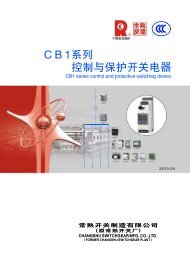
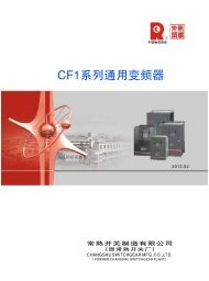
CM2 系 列<br />
CM2Z<br />
塑 料 外 壳 式 断 路 器<br />
系 列<br />
CM2 CM2Z SERIES MOULDED CASE CIRCUIT BREAKER<br />
CV 系 列<br />
CW 系 列<br />
CM 系 列<br />
CB 系 列<br />
CK 系 列 CR 系 列 CA 系 列<br />
CJR 系 列 CJD 系 列 CD 系 列 CH 系 列 CE 系 列<br />
2011.08<br />
常 熟 开 关 制 造 有 限 公 司<br />
( 原 常 熟 开 关 厂 )<br />
CHANGSHUSWITCHGEARMFG. CO.,LTD.<br />
(FORMERCHANGSHUSWITCHGEAR PLANT)
China Well-knownTrademark<br />
National Innovative PilotEnterprise<br />
Postdoctoral Programme<br />
StateTorch Plan Key High-tech<br />
Enterprise<br />
Quality ManagementSystem Certificate<br />
EnvironmentalManagement<br />
System Certificate<br />
OccupationalHealthAnd Safety<br />
Management System Certificate<br />
Certificate OfConformity For<br />
MeasurementManagementSystems
公 司 简 介<br />
Introduction<br />
常 熟 开 关 制 造 有 限 公 司 是 国 有 资 产 参 股 的 电 器 制 造 企 业 、“ 国 家 重 点 高 新 技 术 企<br />
业 ”, 占 地 约 300 亩 , 员 工 1500 人 。 主 要 生 产 中 低 压 电 器 元 件 、 工 控 产 品 、 太 阳 能 光 伏<br />
逆 变 器 、 成 套 装 置 等 , 可 以 为 您 提 供 “ 智 能 配 电 系 统 三 位 一 体 完 整 的 解 决 方 案 ”。<br />
公 司 建 有 博 士 后 科 研 工 作 站 、 省 级 企 业 技 术 中 心 和 江 苏 省 电 器 控 制 工 程 中 心 , 具<br />
有 一 支 以 博 士 、 硕 士 、 本 科 生 为 主 的 多 层 次 研 发 队 伍 , 工 程 技 术 人 员 占 企 业 员 工 总 数<br />
的 45% 左 右 。 公 司 拥 有 先 进 的 模 具 制 造 、 零 部 件 自 动 化 生 产 、 断 路 器 装 配 自 动 检 测 流<br />
水 线 等 一 大 批 先 进 的 制 造 和 试 验 检 测 设 备 ; 实 施 以 ERP 管 理 为 重 点 的 信 息 化 、 网 络 化<br />
管 理 ; 完 善 质 量 / 环 境 / 职 业 健 康 安 全 体 系 , 确 保 为 用 户 提 供 优 质 、 安 全 、 可 靠 的 产<br />
品 。 公 司 “<br />
” 商 标 被 国 家 工 商 行 政 管 理 总 局 认 定 为 中 国 驰 名 商 标 ,CM 系 列 塑 料 外 壳<br />
式 断 路 器 、CW 系 列 智 能 型 万 能 式 断 路 器 曾 双 双 被 评 为 中 国 名 牌 产 品 。<br />
Changshu Switchgear Mfg. Co., Ltd. (Former Changshu Switchgear Plant), an enterprise with stateowned<br />
equity, covered an area of 300,000 m, with 1500 staffs, is a "National Key New High-tech<br />
2<br />
Enterprise" and mainly produces HV and LV electrical components, industry control products, solar<br />
photovoltaic inverters and complete sets of equipment etc, all of which could provide trinity and<br />
complete solutions for intelligent power distribution system.<br />
Post - doctoral scientific research station, Province Enterprise Technique Center and Jiangsu<br />
Province Electrical Apparatus Control Engineering Research Center have been established and a multilevel<br />
professional technique team has been formed consisting of PHD candidates, postgraduates and<br />
university graduates. Engineers and technicians have covered 45% of all staffs.<br />
Advanced mould manufacturing equipments, automation producing equipments for spare parts, assembling<br />
and inspecting lines for breakers and test equipments have been brought in. Meanwhile, information and<br />
network management, taking ERP management as the focal point, has been applied and quality environmental<br />
systems (ISO9001/ISO14001/OHSMS18001) have also been established and perfected to ensure reliability and<br />
safety for customers.<br />
The registered trademark has been recognized as Famous Trademark of China by State Administration<br />
for Industry and Commerce of China. And CM Series Moulded Case Circuit Breaker and CW Series Intelligent<br />
Air Circuit Breaker are both China Top Brand products.
常 熟 开 关 制 造 有 限 公 司<br />
为 您 提 供 电 气 系 统 完 整 的 解 决 方 案<br />
CV1-12 系 列<br />
高 压 真 空 断 路 器<br />
CV2-12 系 列<br />
高 压 真 空 断 路 器<br />
CV1-24 系 列<br />
高 压 真 空 断 路 器<br />
CV1-40.5 系 列<br />
高 压 真 空 断 路 器<br />
CW1 系 列<br />
智 能 型 万 能 式 断 路 器<br />
CW2 系 列<br />
智 能 型 万 能 式 断 路 器<br />
CW3 系 列<br />
智 能 型 万 能 式 断 路 器<br />
CW3V 系 列<br />
智 能 型 真 空 万 能 式 断 路 器<br />
CM1 系 列<br />
塑 料 外 壳 式 断 路 器<br />
CM1 E系 列<br />
电 子 式 塑 壳 断 路 器<br />
CM1 Z系 列<br />
智 能 型 断 路 器<br />
CM1 L系 列<br />
带 剩 余 电 流 保 护 塑 壳 断 路 器<br />
CM1 EL系 列<br />
带 剩 余 电 流 保 护<br />
电 子 可 调 式 断 路 器<br />
CM2 系 列<br />
塑 料 外 壳 式 断 路 器<br />
CM2Z 系 列<br />
智 能 型 塑 壳 断 路 器<br />
CM2L 系 列<br />
带 剩 余 电 流 保 护 塑 壳 断 路 器<br />
CM3 系 列<br />
塑 料 外 壳 式 断 路 器<br />
CM5 系 列<br />
塑 料 外 壳 式 断 路 器<br />
CM5Z 系 列<br />
塑 料 外 壳 式 断 路 器<br />
CA1 系 列 自 动<br />
转 换 开 关 (CB 级 )<br />
CAP1 系 列 自 动<br />
转 换 开 关 (PC 级 )<br />
CAP2 系 列 自 动<br />
转 换 开 关 (PC 级 )<br />
CK3 系 列 接 触 器<br />
CJR3 系 列<br />
热 过 载 继 电 器<br />
CJD3 系 列<br />
电 子 过 载 继 电 器<br />
CLJ3 剩 余 电 流<br />
动 作 继 电 器
常 熟 开 关 制 造 有 限 公 司<br />
为 您 提 供 电 气 系 统 完 整 的 解 决 方 案<br />
CR1 系 列<br />
电 动 机 软 起 动 器<br />
CR2 系 列<br />
电 动 机 软 起 动 器<br />
CD1 系 列<br />
电 动 机 保 护 器<br />
CD4 系 列<br />
智 能 马 达 保 护 器<br />
CB1 系 列<br />
控 制 和 保 护 开 关 电 器 (CPS)<br />
CF1 系 列<br />
通 用 变 频 器<br />
CS1G 系 列 三 相 并 网 型<br />
光 伏 发 电 逆 变 器<br />
CW3G 系 列<br />
隔 离 开 关 ( AC,DC)<br />
CM3DC 系 列<br />
塑 料 外 壳 式 断 路 器<br />
CH 系 列 小 型 断 路 器<br />
CE1 系 列<br />
智 能 型 电 力 仪 表<br />
CI1 系 列<br />
远 程 智 能 I/O 模 块<br />
CN1DP-MP<br />
CN1DP-MD<br />
CN1DP-MC<br />
通 信 适 配 器<br />
CN1EG 以 太 网<br />
适 配 器<br />
FDM3<br />
短 消 息 通 知 模 块<br />
FWB1 温 度 报 警 模 块<br />
CSJ1 系 列 剩 余 电 流 式 电 气<br />
火 灾 监 控 探 测 器 ( 独 立 式 )<br />
CMSJ2 系 列 剩 余 电 流 式 电 气<br />
火 灾 监 控 探 测 器 ( 非 独 立 式 )<br />
CSX1 电 气 火 灾 监 控 设 备<br />
●Riyear-PowerNet 配 电 监 控 系 统<br />
●FCX3 智 能 配 电 监 控 器
优 秀 特 色<br />
CM2 系 列 断 路 器<br />
具 备 TH 型 断 路 器 , 满 足 湿 热 带 地 区 使 用 要 求<br />
获 得 国 际 认 可 的 CB 证 书<br />
高 分 断 、 带 隔 离 、 高 可 靠 、 零 飞 弧 、 体 积 小 、 绿 色 环 保<br />
额 定 极 限 短 路 分 断 能 力 :Icu:400V:35kA~100kA<br />
额 定 运 行 短 路 分 断 能 力 :Ics:400V:35kA~75kA<br />
采 用 新 型 灭 弧 技 术 和 限 流 原 理 , 全 面 提 高 断 路 器 的 性 能 , 其 中 CM2-63 采 用 双 断 点 灭 弧 技 术 ,<br />
Ics=100%Icu=70kA 为 目 前 同 规 格 最 高<br />
热 磁 型 脱 扣 器 可 实 现 热 磁 可 调 , 现 场 可 整 定 过 载 、 瞬 动 的 动 作 值<br />
各 类 附 件 盒 装 化 , 不 用 打 开 断 路 器 , 可 现 场 直 接 安 装<br />
可 配 FWB1 温 度 报 警 模 块 , 实 现 连 接 点 在 线 超 温 报 警<br />
CM2Z 系 列 断 路 器<br />
具 备 TH 型 断 路 器 , 满 足 湿 热 带 地 区 使 用 要 求<br />
获 得 国 际 认 可 的 CB 证 书<br />
高 分 断 、 带 隔 离 、 高 可 靠 、 零 飞 弧 、 体 积 小 、 绿 色 环 保<br />
额 定 极 限 短 路 分 断 能 力 :Icu:400V:70kA~100kA<br />
额 定 运 行 短 路 分 断 能 力 :Ics:400V:50kA~75kA<br />
额 定 短 时 耐 受 电 流 Icw(1s):400V:5kA~8kA<br />
CM2Z 系 列 智 能 型 脱 扣 器 具 有 过 载 长 延 时 、 短 路 短 延 时 、 短 路 瞬 时 的 三 段 保 护 功 能 , 并 具 有 接 地 故 障<br />
( 配 电 型 )、 热 模 拟 保 护 功 能 、 预 报 警 功 能 , 电 动 机 型 断 路 器 还 具 有 不 平 衡 保 护 功 能 。 保 护 参 数 可 连<br />
续 可 调 , 面 板 液 晶 显 示 清 晰 、 直 观 , 并 可 实 现 多 种 调 阅 、 检 查 、 整 定 等 功 能<br />
LCD 显 示 , 菜 单 操 作 方 式 , 并 可 故 障 记 忆 , 使 用 方 便<br />
各 类 附 件 盒 装 化 , 不 用 打 开 断 路 器 , 可 现 场 直 接 安 装<br />
短 路 保 护 具 有 后 备 保 护 , 由 后 备 磁 脱 扣 实 现 快 速 脱 扣 , 限 制 了 短 路 电 流 , 并 确 保 断 路 器 可 靠 分 断<br />
通 信 功 能 模 块 化 实 现 , 通 过 加 装 通 信 模 块 即 可 升 级 为 通 信 型 断 路 器<br />
基 于 Modbus-RTU 协 议 的 通 信 断 路 器 , 通 过 本 公 司 的 CN1DP 适 配 器 、CN1EG 以 太 网 适 配 器 可 应 用 于<br />
Modbus、Profibus、Devicenet、CAN 总 线 和 以 太 网 通 信 网 络 , 方 便 用 户 进 行 多 种 协 议 的 应 用 管 理<br />
通 过 配 置 FDM3 短 消 息 通 知 模 块 , 可 实 现 断 路 器 故 障 脱 扣 或 报 警 信 息 无 线 监 视<br />
可 配 FWB1 温 度 报 警 模 块 , 实 现 连 接 点 在 线 超 温 报 警
目 录<br />
R<br />
概 述<br />
OUTLINE<br />
适 用 工 作 环 境<br />
APPLICABLE ENVIRONMENT<br />
断 路 器 的 分 类<br />
CLASSIFICATION OF CIRCUIT BREAKERS<br />
快 速 选 用 表<br />
TABLE FOR QUICK SELECTION<br />
脱 扣 器 方 式 及 内 部 附 件 代 号<br />
RELEASE PATTERN AND ACCESSORIES CODE<br />
断 路 器 主 要 技 术 性 能 指 标<br />
MAIN TECHNICAL PERFORMANCE INDEX<br />
断 路 器 脱 扣 器 电 流 值<br />
CURRENT VALUE OF BREAKER RELEASE<br />
CM2 断 路 器 保 护 特 性<br />
PROTECTION CHARACTERISTIC OF CM2 CIRCUIT BREAKERS<br />
CM2 断 路 器 保 护 特 性 曲 线<br />
PROTECTION CHARACTERISTIC CURVE OF CM2 CIRCUIT BREAKERS<br />
CM2Z 断 路 器 保 护 特 性<br />
PROTECTION CHARACTERISTIC OF CM2Z CIRCUITBREAKERS<br />
CM2Z 断 路 器 保 护 特 性 曲 线<br />
PROTECTION CHARACTERISTIC CURVE OF CM2Z CIRCUIT BREAKERS<br />
外 形 尺 寸 及 安 装 尺 寸<br />
OUTLINEDIMENSIONS AND MOUNTING DIMENSIONS<br />
断 路 器 安 装 安 全 间 隙<br />
MOUNTING SAFETY CLEARANCE<br />
内 外 部 附 件<br />
INTERNAL /EXTERNAL ACCESSORIES<br />
不 同 额 定 电 流 的 连 接 导 线 参 考 截 面<br />
CROSS-SECTION AREA OFWIRINGCABLEAND CORRESPONDING RATED CURRENT<br />
接 线 端 子 型 号<br />
TYPEOF WIRING TERMINAL<br />
FWB1 温 度 报 警 模 块<br />
TEMPERATURE ALARM MODULE<br />
功 耗 及 降 容 系 数<br />
POWER WASTAGE AND CAPACITY REDUCING FACTOR<br />
高 海 拔 降 容<br />
CAPACITY-REDUCING FOR HIGH-ELEVATION<br />
CM2(Z) 限 流 特 性<br />
CM2 LIMITED CHARACTERISTIC<br />
CM2Z/T 断 路 器 通 信 功 能<br />
COMMUNICATIVEFUNCTION OF CM2Z/T<br />
使 用 与 维 护<br />
USEAND MAINTENANCE<br />
订 货 须 知<br />
ORDERING NOTICE<br />
订 货 规 范<br />
ORDERING FORM<br />
1<br />
1<br />
2<br />
3<br />
4<br />
6<br />
11<br />
12<br />
14<br />
19<br />
21<br />
23<br />
33<br />
34<br />
46<br />
46<br />
47<br />
49<br />
50<br />
50<br />
52<br />
58<br />
58<br />
59
概<br />
述<br />
CM2 系 列 、 CM2 Z 系 列 塑 料 外 壳 式 断 路 器 ( 以<br />
下 简 称 断 路 器 ), 是 本 公 司 采 用 国 际 先 进 设 计 技<br />
术 研 制 , 根 据 IEC60947-2 国 际 新 标 准 的 要 求 开 发 的<br />
新 型 断 路 器 。 其 额 定 绝 缘 电 压 为 800V, 适 用 于 交<br />
流 50Hz/60Hz、 额 定 工 作 电 压 400V 及 以 下 、 额 定<br />
电 流 至 630A 的 电 路 中 作 不 频 繁 转 换 之 用 。 断 路 器<br />
具 有 过 载 、 短 路 和 欠 电 压 保 护 功 能 , 能 保 护 线 路<br />
和 电 源 设 备 不 受 损 坏 。<br />
断 路 器 按 照 其 短 路 分 断 能 力 的 高 低 , 分 为<br />
L 型 ( 标 准 型 )、M 型 ( 较 高 分 断 型 )、H 型 ( 高<br />
分 断 型 ) 三 类 。<br />
断 路 器 可 垂 直 安 装 ( 即 竖 装 ), 亦 可 水 平 安<br />
装 ( 即 横 装 )。<br />
断 路 器 不 能 倒 进 线 , 即 只 可 1、3、5 接 电 源<br />
线 ,2、4、6 接 负 载 线 。<br />
断 路 器 具 有 隔 离 功 能 , 其 相 应 的 符 号 为 :<br />
。<br />
断 路 器 执 行 下 列 标 准 :<br />
IEC60947-1 及 GB14048.1-2006 总 则<br />
IEC60947-2 及 GB14048.2-2008 断 路 器<br />
IEC60947-4-1 及 GB 14048.4 机 电 式 接 触 器 和<br />
电 动 机 起 动 器<br />
断 路 器 获 国 家 强 制 性 产 品 认 证 “CCC” 标<br />
志 。<br />
CM2 and CM2Z Series Moulded Case Circuit<br />
Breakers (hereafter simply referred to as circuit<br />
breakers) are one of the new type breakers which have<br />
been developed by the company using international<br />
advanced design and manufaturing technology. The<br />
rated insulationvoltage of the breakers is 800V. In the<br />
circuit of AC50Hz/60Hz, rated working voltage 400V<br />
(or below) and rated working current up to 630A, the<br />
breakers take the role of infrequentturn-onorturn-off .<br />
The breakers have overload, short-circuit and undervoltage<br />
protection performances so as to protect the<br />
circuit and thepower equipment fromdamage.<br />
The circuit breakers, according to the level of<br />
short-circuit breaking capacity, can be classified into<br />
three categories: type L(typical type), type M(second<br />
highbreakingtype) and typeH(highbreakingtype).<br />
The circuit breakers can be installed vertically<br />
(upright)or horizontally(transverse).<br />
The breakers can't be wired adversely 1,3 and 5<br />
can only be connected with power line; 2,4 and 6only<br />
beconnected with load line.<br />
The circuit breaker has disconnecting function<br />
and its corresponding symbol is shown as .<br />
The circuit breakers comply with the demands of<br />
thefollowingstandards:<br />
IEC60947-1 and GB14048.1-2006 General<br />
IEC60947-2 and GB14048.2-2008<br />
Circuit-breakers<br />
IEC60947-4-1 andGB14048.4<br />
Electro-mechanical contactorand motor starter<br />
The circuit breakershave obtained the CCC mark<br />
of CQC.<br />
适 用 工 作 环 境<br />
周 围 介 质 温 度 不 高 于 +40℃ 和 不 低 于<br />
-5℃, 且 24h 的 平 均 值 不 超 过 +35℃。<br />
海 拔 2000m 以 下 。<br />
安 装 地 点 的 空 气 相 对 湿 度 在 最 高 温 度 为<br />
+40℃ 时 不 超 过 50%, 在 较 低 温 度 下 可 以 有 较 高<br />
的 相 对 湿 度 , 例 如 20℃ 时 达 90%( 湿 热 带 型 断 路<br />
器 25 ℃ 时 可 达 95%)。 对 于 温 度 变 化 偶 尔 产 生 的<br />
凝 露 应 采 取 特 殊 措 施 。<br />
污 染 等 级 为 3 级 。<br />
断 路 器 主 电 路 及 欠 电 压 脱 扣 器 安 装 类 别 为<br />
Ⅲ, 其 余 辅 助 电 路 、 控 制 电 路 安 装 类 别 为 Ⅱ。<br />
断 路 器 适 用 于 电 磁 环 境 A;<br />
湿 热 带 型 (TH 型 ) 断 路 器 能 耐 受 湿 热 、 盐<br />
雾 、 雾 菌 的 影 响 。<br />
断 路 器 应 安 装 在 无 爆 炸 危 险 和 无 导 电 尘 埃 、<br />
无 足 以 腐 蚀 金 属 和 破 坏 绝 缘 的 地 方 。<br />
断 路 器 应 安 装 在 没 有 雨 雪 侵 袭 的 地 方 。<br />
Ambient temperature:-5℃ ~+40℃ and the<br />
average in24 hours below+35.<br />
Elevation≤2000m.<br />
Relative humidity: not exceed 50% at the<br />
maximum ambient temperature of +40℃ , but higher<br />
relative humidity at the lower temperature, for example,<br />
90% at 20℃ (Relative humidity of the humid tropical<br />
area breakers isn't exceeding 95% at the temperature of<br />
+25℃).Special measures should be taken considering<br />
the dewsonproduct surface dueto temperaturechange.<br />
Pollution protection:3 grade.<br />
Installing categories: III for the main circuit and<br />
under-voltage release of the breakers, and II for other<br />
auxiliary and controlcircuits.<br />
The breakers are suitable in electromagnic<br />
environment A.<br />
The breakers used in humid tropical(TH) area can<br />
work normally without influence of humid air, salt fog<br />
and milder.<br />
There must be not any explosive medium, and<br />
there must be not any gas which would corrode metal or<br />
any conducting dust whichwould destroy the insulation.<br />
The placewouldnotbe invadedbyrain and snow.<br />
1
断 路 器 的 分 类<br />
型 号 及 其 含 义 如 下<br />
Typeandits meaning<br />
常 熟 开 关 制 造 有 限 公 司<br />
Changshu SwitchgearManufacturingCo.,Ltd<br />
塑 料 外 壳 式 断 路 器<br />
Moulded Case CircuitBreaker<br />
设 计 代 号<br />
DesignCode<br />
4)<br />
系 列 派 生 代 号<br />
SerialDerivativeCode 4)<br />
壳 架 等 级 额 定 电 流<br />
Rated Frame Current<br />
短 路 分 断 能 力 级 别<br />
GradeofShort-CircuitBreakingCapacity<br />
C M 2 - / /<br />
注 : 1) 配 电 用 断 路 器 无 代 号 , 保 护 电 动 机 用 断 路 器 以 2 表<br />
示 ;<br />
2) 智 能 型 脱 扣 器 不 带 通 信 无 代 号 , 带 通 信 用 T 表 示 ;<br />
3) 直 接 操 作 无 代 号 , 电 动 操 作 用 P 表 示 , 转 动 手 柄 操<br />
作 用 Z 表 示 ;<br />
4) 热 磁 型 脱 扣 器 无 代 号 , 智 能 型 脱 扣 器 用 Z 表 示 。<br />
四 极 时 N 极 型 式<br />
N-Pole Modefor 4Poles<br />
1)<br />
用 途 代 号<br />
ApplicationCode 1)<br />
脱 扣 器 方 式 及 内 部 附 件 代 号<br />
Release PatternandInternalAccessoriesCode<br />
极 数 Pole Number<br />
2)<br />
智 能 型 脱 扣 器 派 生 代 号<br />
3)<br />
操 作 方 式<br />
Operation pattern 3)<br />
湿 热 带 型 代 号 :TH<br />
Humidtropicalarea code:TH<br />
DerivativeCodeof Intelligent Release 2)<br />
Note:<br />
1)No code forPowerDistribution;2formotorprotection.<br />
2)TforIntelligent ReleasewithCommunication interface.<br />
3)No code fordirectoperation;PforPower-driven;ZforManuallyhandled.<br />
4) No code for Thermo-magnetic Release;Zfor Intelligent Release.<br />
按 产 品 极 数 分 为 三 极 与 四 极 。 四 极 产 品 中 中<br />
性 极 (N 极 ) 的 型 式 分 四 种 :<br />
A 型 :N 极 不 安 装 过 电 流 脱 扣 器 , 且 N 极 始 终<br />
接 通 , 不 与 其 它 三 极 一 起 合 分 ;<br />
B 型 :N 极 不 安 装 过 电 流 脱 扣 器 , 且 N 极 与 其<br />
它 三 极 一 起 合 分 (N 极 先 合 后 分 );<br />
C 型 :N 极 安 装 过 电 流 脱 扣 器 , 且 N 极 与 其 它<br />
三 极 一 起 合 分 (N 极 先 合 后 分 );<br />
D 型 :N 极 安 装 过 电 流 脱 扣 器 , 且 N 极 始 终 接<br />
通 , 不 与 其 它 三 极 一 起 合 分 。<br />
注 : 建 筑 物 内 实 施 等 电 位 联 结 的 TN-C-S 和<br />
TN-S 系 统 , 中 性 极 型 式 推 荐 采 用 A 型 或 D 型 。<br />
按 接 线 方 式 分 为 板 前 接 线 、 板 后 接 线 、 插 入<br />
式 接 线 、 抽 出 式 接 线 四 种 。<br />
按 过 电 流 脱 扣 器 型 式 分 热 磁 型 脱 扣 器 及 智 能<br />
型 脱 扣 器 两 大 类 ; 热 磁 型 脱 扣 器 又 可 分 为 瞬 时 脱<br />
扣 器 、 复 式 脱 扣 器 ( 瞬 时 脱 扣 器 和 热 动 脱 扣 器 )<br />
两 种 。<br />
按 断 路 器 是 否 带 附 件 分 带 附 件 和 不 带 附 件 两<br />
种 , 附 件 分 内 部 附 件 和 外 部 附 件 : 内 部 附 件 有 分<br />
励 脱 扣 器 、 欠 电 压 脱 扣 器 、 辅 助 触 头 、 报 警 触 头<br />
四 种 ; 外 部 附 件 有 手 动 操 作 机 构 、 电 动 操 作 机<br />
构 、CM2Z 专 用 测 试 器 、FWB1 温 度 报 警 模 块 等 。<br />
According to the pole number of product, it<br />
classifies, three-andfour-poles .<br />
The neutral pole (N-pole) of the four-poles<br />
products has four types:<br />
Type A:N-polewithoutover-current release unit,it<br />
has been connected all along, and does not act withother<br />
three poles toturnonor off.<br />
Type B: N-pole without overcurrent release unit, it<br />
could act withother three poles. (N-pole turns-onprior to<br />
turns-off.)<br />
Type C:N-polefixedwith over-currentreleaseunit,<br />
it couldact with otherthree poles. (N-pole turns-onprior<br />
to turns-off. )<br />
Type D:N-polefixedwith over-currentreleaseunit,<br />
it has been connected all along, and does not act with<br />
other three poles to turn onoroff.<br />
Note: Inside building, if the breakers used in TN-<br />
C-S and TN-S system which is equipotential bond, the<br />
patternof neutral poleis recommended to adopt Atype or<br />
Dtype.<br />
The wiring method has four ways: wiring in front of<br />
the board, wiring on back of the board,wiringby insertion<br />
and wiring of draw-out.<br />
According to theover-current release pattern,it can<br />
be classified into two types: Thermo-magnetic Release<br />
and Intelligent Release; furthermore, the Thermomagnetic<br />
Release can be also classified into two types:<br />
Instantaneous Release and Double Release<br />
(InstantaneousReleaseandThermodynamicRelease).<br />
According to theoutfit,it also has two types: with or<br />
without outfit.The outfit includes internal accessories and<br />
external accessories: The internal accessories have four<br />
kinds: shunt release, under-voltage release, auxiliary<br />
contactor and alarm contactor. The external accessories<br />
are turning handle operation mechanism, power-driven<br />
operation mechanism and CM2Z-exclusive Tester、<br />
FWB1temperature alarm module etc.<br />
2
快 速 选 用 表<br />
3
脱 扣 器 方 式 及 内 部 附 件 代 号<br />
左 面 安 装<br />
Right mounting<br />
手 柄<br />
Handle<br />
右 面 安 装<br />
Rightmounting<br />
报 警 触 头 Alarmcontactor<br />
辅 助 触 头 Auxiliary contactor<br />
分 励 脱 扣 器 Shuntrelease<br />
欠 电 压 脱 扣 器 Under-voltagerelease<br />
引 线 方 向 Lead direction<br />
脱<br />
扣 器<br />
方 式<br />
及 内 部<br />
附 件 代 号<br />
Coderelease<br />
pattern and<br />
internal<br />
accessories<br />
型 号 Type<br />
极 数<br />
附 件 名 称 Polenumber<br />
Accessoriesname<br />
CM2-63<br />
3、4<br />
CM2-125<br />
3、4<br />
CM2-225<br />
3、4<br />
CM2-400<br />
3、4<br />
CM2-630<br />
3、4<br />
208、308<br />
报 警 触 头<br />
Alarmcontactor<br />
210、310<br />
分 励 脱 扣 器<br />
Shuntrelease<br />
220、320<br />
辅 助 触 头<br />
Auxiliarycontactor<br />
230、330<br />
欠 电 压 脱 扣 器<br />
Under-voltage release<br />
240、340<br />
分 励 脱 扣 器 辅 助 触 头<br />
Shuntrelease auxiliary contactor<br />
250、350<br />
分 励 脱 扣 器 欠 电 压 脱 扣 器<br />
Shunt release under-voltage release<br />
260、360<br />
二 组 辅 助 触 头<br />
Two groups ofauxiliary contactor<br />
270、370<br />
辅 助 触 头 欠 电 压 脱 扣 器<br />
Auxiliarycontactorunder-voltagerelease<br />
218、318<br />
分 励 脱 扣 器 报 警 触 头<br />
Shunt release Alarm contactor<br />
228、328<br />
辅 助 触 头 报 警 触 头<br />
AuxiliarycontactorAlarm contactor<br />
238、338<br />
欠 电 压 脱 扣 器 报 警 触 头<br />
Under-voltage releaseAlarmcontactor<br />
248、348 分 励 脱 扣 器 辅 助 触 头 报 警 触 头<br />
Shunt releaseauxiliarycontactorAlarmcontactor<br />
268、368 二 组 辅 助 触 头 报 警 触 头<br />
TwogroupsofAuxilitorycontactorAlarmcontactor<br />
278、378 辅 助 触 头 欠 电 压 脱 扣 器 报 警 触 头<br />
Auxiliarycontactorunder-voltage relaxeAlarmcontactor<br />
注 :1. 000: 表 示 无 热 动 或 电 磁 脱 扣 器 ,200: 表 示 仅 有 电 磁 脱 扣 器 的 CM2 断 路 器 ,300 表 示 带 有 热 动 - 电 磁 脱 扣 器 的 CM2 断 路 器 。<br />
2. 对 CM2-400 及 CM2-630 其 中 248、348、278、378 规 格 中 辅 助 触 头 为 一 对 触 头 ( 即 一 常 开 一 常 闭 ),268、368 规 格 中 的 辅 助 触 头 为<br />
三 对 触 头 ( 即 三 常 开 三 常 闭 ); 其 余 规 格 辅 助 触 头 数 量 按 P36 表 中 配 置 。<br />
3. 对 CM2-63、CM2-125 及 CM2-225 其 中 220、320、240、340、270、370 规 格 中 辅 助 触 头 可 供 二 对 触 头 ( 即 二 常 开 二 常 闭 ),260、<br />
360 可 供 三 对 触 头 ( 即 三 常 开 三 常 闭 ), 但 订 货 时 需 注 明 。<br />
Note:1.000:Breaker has not any thermo or electromagnic release;200:breaker only has electromagnetic release pattern; 300:breaker has thermoelectromagenticrelease<br />
pattern.<br />
2. ForCM2-400 and CM2-630;codes 248、348、278、.378only have one pairofauxilliary contacts (anormalopened, anormalclosed); but<br />
268、368 have three pairs of auxilliary contacts (three normal opened, three normal closed). The amount of auxilliary contacts in terms of<br />
other specifications is disposed accordingto the diagrams on page 36.<br />
3. For CM2-63、CM2-125<br />
and CM2-225,code 220、320、240、340、270 and 370 can provide two pairs ofauxilliary contacts(two normal<br />
opened, two normal closed), while code 260 and 360can provide three pairs of auxilliary contacts (threenormalopened, three normalclosed),<br />
note when makingorder.<br />
4
脱 扣 器 方 式 及 内 部 附 件 代 号<br />
左 面 安 装<br />
Leftmounting<br />
手 柄<br />
Handle<br />
右 面 安 装<br />
Rightmounting<br />
报 警 触 头 Alarmcontaetor<br />
辅 助 触 头 Auxiliary contactor<br />
分 励 脱 扣 器 Shunt release<br />
欠 电 压 脱 扣 器 Under-voltage release<br />
引 线 方 向 Leaddirection<br />
脱<br />
扣 器<br />
方 式<br />
及 内 部<br />
附 件 代 号<br />
Coderelease<br />
pattern and<br />
internal<br />
accessories<br />
型 号 Type<br />
极 数<br />
附 件 名 称 Polenumber<br />
Accessoriesname<br />
CM2Z-125 CM2Z-225 CM2Z-400 CM2Z-630<br />
3、4 3、4 3、4<br />
3、4<br />
308<br />
报 警 触 头<br />
Alarm contactor<br />
310<br />
分 励 脱 扣 器<br />
Shunt release<br />
320<br />
辅 助 触 头<br />
Auxiliarycontactor<br />
330<br />
欠 电 压 脱 扣 器<br />
Under-voltage release<br />
328<br />
辅 助 触 头 报 警 触 头<br />
AuxiliarycontactorAlarm contactor<br />
注 :300: 表 示 不 带 附 件 的 CM2Z 断 路 器<br />
Note:300: forCM2Z circuitbreakerwithout accessorieslistedin table.<br />
5
断 路 器 主 要 技 术 性 能 指 标<br />
壳 架 等 级 额 定 电 流 Inm(A)<br />
Ratedframecurrent<br />
型 号 Type<br />
63<br />
CM2-63L CM2-63M CM2-63H<br />
额 定 电 流 In(A)<br />
Ratedcurrent<br />
整 定 电 流 调 节 范 围 Ir 1(A)<br />
Band ofregulatedsetting current<br />
CM2<br />
6**、10、16、20、25、32、40、50、63<br />
( 0.8-0.9-1.0)<br />
In<br />
极 数 Polenumber<br />
3<br />
3<br />
4<br />
3<br />
4<br />
额 定 绝 缘 电 压 Ui(V)<br />
Ratedinsulation voltage<br />
AC800<br />
额 定 冲 击 耐 受 电 压 Uimp(V)<br />
Ratedimpulsewithstandvoltage<br />
8000<br />
额 定 工 作 电 压 Ue(V)<br />
Rateworkingvoltage<br />
AC400<br />
飞 弧 距 离 (mm)<br />
Arc distance<br />
0<br />
额 定 极 限 短 路 分 断 能 力<br />
Icu(kA)<br />
Limiting short-circuit breaking ability<br />
额 定 运 行 短 路 分 断 能 力<br />
Ics(kA)<br />
Operatingshort-circuit breakingability<br />
AC400V<br />
AC400V<br />
35<br />
35<br />
50<br />
50<br />
70<br />
70<br />
使 用 类 别<br />
Utilizationcategory<br />
A<br />
电 气 寿 命 *( 次 times)<br />
electrical durability<br />
8000<br />
机 械 寿 命 *( 次 times)<br />
mechanicaldurability<br />
免 维 护<br />
freemaintenance<br />
有 维 护<br />
maintenance<br />
20000<br />
40000<br />
外 形 尺 寸 (mm)<br />
Outline Dimersions<br />
W<br />
78<br />
78<br />
103<br />
78<br />
103<br />
L<br />
135<br />
W<br />
H<br />
H<br />
81.5<br />
* 注 : 根 据 GB14048.1-2006, 术 语 “ 寿 命 ” 表 示 电 器 在 修 理 或 更 换 部 件 前 能 完 成 的 操 作 循 环 次 数 的 概 率 。<br />
*Note:for GB14048.1-2006,the term"durability"expressesthe expectancyofthenumber of operatingcycles which can beperformed<br />
by the equipment beforerepair orreplacement ofparts<br />
** 注 :CM2-63 中 6A 规 格 无 过 载 保 护 。<br />
**Note:withoutoverloadprotectionfor 6A ofCM2-63.<br />
6
断 路 器 主 要 技 术 性 能 指 标<br />
壳 架 等 级 额 定 电 流 Inm(A)<br />
Ratedframecurrent<br />
125<br />
型 号 Type<br />
CM2-125L<br />
CM2-125M<br />
CM2Z-125M<br />
CM2-125H<br />
CM2Z-125H<br />
额 定 电 流 In(A)<br />
Ratedcurrent<br />
整 定 电 流 调 节 范 围<br />
Ir 1(A)<br />
Band ofregulatedsetting current<br />
CM2<br />
CM2Z<br />
CM2<br />
CM2Z**<br />
16、 20、 25、 32、 40、 50、 63、 80、 100、<br />
125<br />
32、 63、<br />
125<br />
( 0.8-0.9-1.0)<br />
In<br />
32( 16~32)、 63( 32~63)、 125( 63~125)<br />
极 数 Polenumber<br />
3<br />
3<br />
4<br />
3<br />
4<br />
额 定 绝 缘 电 压 Ui(V)<br />
Ratedinsulation voltage<br />
额 定 冲 击 耐 受 电 压 Uimp(V)<br />
Ratedimpulsewithstandvoltage<br />
额 定 工 作 电 压 Ue(V)<br />
Rateworkingvoltage<br />
飞 弧 距 离 (mm)<br />
Arc distance<br />
额 定 极 限 短 路 分 断 能 力<br />
Icu(kA)<br />
Limiting short-circuitbreaking ability<br />
额 定 运 行 短 路 分 断 能 力<br />
Ics(kA)<br />
Operatingshort-circuitbreakingability<br />
使 用 类 别<br />
Utilizationcategory<br />
机 械 寿 命 ( 次 times)<br />
mechanicaldurability<br />
外 形 尺 寸 (mm)<br />
OutlineDimersions<br />
电 气 寿 命 ( 次 times)<br />
electrical durability<br />
AC400V<br />
AC400V<br />
免 维 护<br />
freemaintenance<br />
有 维 护<br />
maintenance<br />
W<br />
L<br />
50 70 85<br />
35<br />
AC800<br />
8000<br />
AC400<br />
≯ 50( 0* )<br />
50<br />
A<br />
8000<br />
20000<br />
40000<br />
92 92 122 92 122<br />
150<br />
70<br />
W<br />
H<br />
H<br />
85<br />
* 注 : 选 装 高 为 5mm 的 零 飞 弧 罩 , 实 现 零 飞 弧 。<br />
** 注 : CM2Z整 定 电 流 连 续 可 调 。<br />
Note:Zero arc distancebyinstallingarc coverof 5mm inheight<br />
Note:The setting currentofCM2Zis successivelyadjusted<br />
7
断 路 器 主 要 技 术 性 能 指 标<br />
壳 架 等 级 额 定 电 流 Inm(A)<br />
Ratedframecurrent<br />
225<br />
型 号 Type<br />
CM2-225L<br />
CM2-225M<br />
CM2Z-225M<br />
CM2-225H<br />
CM2Z-225H<br />
额 定 电 流 In(A)<br />
Ratedcurrent<br />
整 定 电 流 调 节 范 围<br />
Ir 1(A)<br />
Bandofregulated setting current<br />
极 数 Polenumber<br />
CM2<br />
CM2Z<br />
CM2<br />
CM2Z**<br />
125、 140、 160、 180、 200、<br />
225<br />
225<br />
( 0.8-0.9-1.0)<br />
In<br />
225( 125~225)<br />
3 3 4 3 4<br />
额 定 绝 缘 电 压 Ui(V)<br />
Ratedinsulation voltage<br />
额 定 冲 击 耐 受 电 压 Uimp(V)<br />
Ratedimpulse withstandvoltage<br />
额 定 工 作 电 压 Ue(V)<br />
Rateworkingvoltage<br />
飞 弧 距 离 (mm)<br />
Arc distance<br />
额 定 极 限 短 路 分 断 能 力<br />
Icu(kA)<br />
Limiting short-circuitbreakingability<br />
额 定 运 行 短 路 分 断 能 力<br />
Ics(kA)<br />
Operatingshort-circuitbreaking ability<br />
使 用 类 别<br />
Utilization category<br />
机 械 寿 命 ( 次 times)<br />
mechanicaldurability<br />
外 形 尺 寸 (mm)<br />
OutlineDimersions<br />
AC400V<br />
AC400V<br />
电 气 寿 命 ( 次 times)<br />
electricaldurability<br />
8000<br />
免 维 护<br />
freemaintenance<br />
有 维 护<br />
maintenance<br />
W<br />
50<br />
35<br />
AC800<br />
8000<br />
AC400<br />
≯ 50( 0* )<br />
70<br />
50<br />
A<br />
20000<br />
40000<br />
85<br />
70<br />
107 107 142 107 142<br />
L<br />
165<br />
W<br />
H<br />
H<br />
85<br />
* 注 : 选 装 高 为 6mm 的 零 飞 弧 罩 , 实 现 零 飞 弧 。<br />
** 注 :CM2Z 整 定 电 流 连 续 可 调 。<br />
Note:Zero arc distancebyinstallingarc coverof 6mm inheight<br />
Note:The setting currentofCM2Zis successivelyadjusted<br />
8
断 路 器 主 要 技 术 性 能 指 标<br />
壳 架 等 级 额 定 电 流 Inm(A)<br />
Ratedframecurrent<br />
400<br />
型 号 Type<br />
CM2-400L<br />
CM2-400M<br />
CM2Z-400M***<br />
CM2-400H<br />
CM2Z-400H***<br />
额 定 电 流 In(A)<br />
Ratedcurrent<br />
整 定 电 流 调 节 范 围<br />
Ir 1(A)<br />
Bandofregulated setting current<br />
CM2<br />
CM2Z<br />
CM2<br />
CM2Z**<br />
225、 250、 315、 350、<br />
400<br />
400<br />
( 0.8-0.9-1.0)<br />
In<br />
400( 200~400)<br />
极 数<br />
Pole number<br />
额 定 绝 缘 电 压 Ui(V)<br />
Ratedinsulation voltage<br />
额 定 冲 击 耐 受 电 压 Uimp(V)<br />
Rated impulsewithstandvoltage<br />
额 定 工 作 电 压 Ue(V)<br />
Rateworkingvoltage<br />
飞 弧 距 离 (mm)<br />
Arc distance<br />
额 定 极 限 短 路 分 断 能 力<br />
Icu(kA)<br />
Limiting short-circuitbreaking ability<br />
额 定 运 行 短 路 分 断 能 力<br />
Ics(kA)<br />
Operatingshort-circuitbreaking ability<br />
使 用 类 别<br />
Utilizationcategory<br />
机 械 寿 命 ( 次 times)<br />
mechanicaldurability<br />
外 形 尺 寸 (mm)<br />
OutlineDimersions<br />
AC400V<br />
AC400V<br />
电 气 寿 命 ( 次 times)<br />
electricaldurability<br />
7500<br />
免 维 护<br />
freemaintenance<br />
有 维 护<br />
maintenance<br />
W<br />
3 3 4 3 4<br />
AC800<br />
8000<br />
AC400<br />
≯ 100( 0* )<br />
50 70 100<br />
50 70 75<br />
A/CM2-400,B/CM2Z-400<br />
10000<br />
20000<br />
150 150 198 150 198<br />
L<br />
257<br />
W<br />
H<br />
H<br />
110<br />
* 注 : 选 装 高 为 10.5mm 的 零 飞 弧 罩 , 实 现 零 飞 弧 。<br />
** 注 :CM2Z 整 定 电 流 连 续 可 调 。<br />
***<br />
注 :CM2Z-400 的 额 定 短 时 耐 受 电 流 Icw(1s)=5kA。<br />
Note: Zero arc distancebyinstalling arc coverof 10.5mmin height<br />
Note: The setting currentofCM2Zis successivelyadjusted<br />
Note: Ratedwithstand current forshorttime ofCM2Z-400Icw (1s)=5kA<br />
9
断 路 器 主 要 技 术 性 能 指 标<br />
壳 架 等 级 额 定 电 流 Inm(A)<br />
Ratedframe current<br />
630<br />
型 号 Type<br />
CM2-630L<br />
CM2-630M<br />
CM2Z-630M***<br />
CM2-630H<br />
CM2Z-630H***<br />
额 定 电 流 In(A)<br />
Ratedcurrent<br />
整 定 电 流 调 节 范 围<br />
Ir 1(A)<br />
Bandof regulatedsetting current<br />
CM2<br />
CM2Z<br />
CM2<br />
CM2Z**<br />
400、 500、<br />
630<br />
630<br />
( 0.8-0.9-1.0)<br />
In<br />
630( 315~630)<br />
极 数 Polenumber<br />
3<br />
3<br />
4<br />
3<br />
4<br />
额 定 绝 缘 电 压 Ui(V)<br />
Ratedinsulation voltage<br />
额 定 冲 击 耐 受 电 压 Uimp(V)<br />
Ratedimpulse withstandvoltage<br />
额 定 工 作 电 压 Ue(V)<br />
Rateworkingvoltage<br />
飞 弧 距 离 (mm)<br />
Arc distance<br />
额 定 极 限 短 路 分 断 能 力<br />
Icu(kA)<br />
Limiting short-circuit breaking ability<br />
额 定 运 行 短 路 分 断 能 力<br />
Ics(kA)<br />
Operating short-circuitbreakingability<br />
使 用 类 别<br />
Utilization category<br />
机 械 寿 命 ( 次 times)<br />
mechanicaldurability<br />
外 形 尺 寸 (mm)<br />
Outline dimersions<br />
AC400V<br />
AC400V<br />
电 气 寿 命 ( 次 times)<br />
electricaldurability<br />
7500<br />
免 维 护<br />
freemaintenance<br />
有 维 护<br />
maintenance<br />
W<br />
50<br />
50<br />
AC800<br />
8000<br />
AC400<br />
≯ 100( 0* )<br />
70<br />
70 75<br />
A/CM2-630,B/CM2Z-630<br />
10000<br />
20000<br />
100<br />
182 182 240 182 240<br />
L<br />
270<br />
W<br />
H<br />
H<br />
110<br />
* 注 : 选 装 高 为 11.5mm 的 零 飞 弧 罩 , 实 现 零 飞 弧 。<br />
** 注 :CM2Z 整 定 电 流 连 续 可 调 。<br />
***<br />
注 :CM2Z-630 的 额 定 短 时 耐 受 电 流 Icw(1s)=8kA。<br />
Note:Zeroarcdistancebyinstalling arccover of11.5mm inheight<br />
Note:The setting currentof CM2Zissuccessivelyadjusted<br />
Note:Ratedwithstand currentforshorttime ofCM2Z-630Icw(1s)=8kA<br />
10
断 路 器 脱 扣 器 电 流 值<br />
常 规 出 厂 的 断 路 器 相 极 和 中 性 极 脱 扣 器 电 流<br />
值 见 表 一 及 表 二 。 四 极 断 路 器 中 性 极 (N) 设 在<br />
产 品 右 侧 。CM2、CM2Z 四 极 断 路 器 中 性 极 型 式 为<br />
A 型 、B 型 时 无 过 电 流 保 护 ;CM2 中 性 极 型 式 为<br />
C 型 、D 型 N 极 脱 扣 器 的 额 定 电 流 、 整 定 电 流 见 表<br />
一 ;CM2Z 中 性 极 型 式 为 C 型 、D 型 N 极 脱 扣 器 的 额<br />
定 电 流 、 整 定 电 流 见 表 二 , 但 用 户 也 可 自 行 100%<br />
保 护 设 定 。<br />
Neutral pole (N) is on the right side of the fourpole<br />
breaker. For CM2 and CM2Z four-pole breakers.<br />
When the neutral pole type is Aor B, the breakers<br />
haven't over-current protection; For CM2 four-pole<br />
breakers, when the neutral pole type is Cor D, the<br />
rated current and setting current of N pole of the<br />
release see table one; For CM2Z four-pole breaker,<br />
when the neutral pole type is Cor D, the rated current<br />
and setting current of Npole of the release see table<br />
two, butuserscan set 100% protection.<br />
壳 架 等 级<br />
额 定 电 流<br />
Inm(A)<br />
Framerated<br />
current<br />
63<br />
125<br />
225<br />
400<br />
630<br />
额 定 电 流 In<br />
(A)<br />
Rated<br />
current<br />
10<br />
16<br />
20<br />
25<br />
32<br />
40<br />
50<br />
63<br />
16<br />
20<br />
25<br />
32<br />
40<br />
50<br />
63<br />
80<br />
100<br />
125<br />
125<br />
140<br />
160<br />
180<br />
200<br />
225<br />
225<br />
250<br />
315<br />
350<br />
400<br />
400<br />
500<br />
630<br />
断 路 器 相 极 Phase pole<br />
表 一 Table 1<br />
整 定 电 流 (A)<br />
整 定 电 流 (A)<br />
Setting current<br />
Setting current<br />
额 定 电 流 IN<br />
热 动 型 电 磁 脱 扣 器 Ir 3 (A)<br />
(A)<br />
电 磁 脱 扣 器 Ir 3N(A)<br />
Electromagnetic release<br />
热 动 型 脱 Electromagnetic release<br />
脱 扣 器<br />
Rated 扣 器 Ir1N<br />
Ir 1(A)<br />
配 电 型 电 动 机 型<br />
配 电 型 电 动 机 型<br />
current Thermodynamic<br />
Thermodynamic Forpower For motor<br />
Forpower For motor<br />
release<br />
release distribution protection<br />
distribution protection<br />
- -<br />
6 6<br />
1.0In<br />
(0.8-0.9-1.0)In<br />
(0.8-0.9-1.0)In<br />
10<br />
16<br />
20<br />
25<br />
32<br />
40<br />
50<br />
63<br />
16<br />
20<br />
25<br />
32<br />
40<br />
50<br />
63<br />
63<br />
63<br />
63<br />
125<br />
125<br />
125<br />
125<br />
125<br />
125<br />
225<br />
225<br />
225<br />
225<br />
225<br />
400<br />
400<br />
400<br />
10In±20% 12In±20% (0.8-0.9-1.0)IN 10I N±20%<br />
12I N±20%<br />
(5-6-7-8<br />
-9-10)In<br />
±20%<br />
(10-12-<br />
14)In±20%<br />
断 路 器 中 性 极 (N) Neutralpole<br />
(0.8-0.9-1.0)IN<br />
(5-6-7-8<br />
-9-10)I N<br />
±20%<br />
(10-12-<br />
14)I N±20%<br />
注 :1 常 规 出 厂 的 CM2 四 极 断 路 器 中 性 极 电 流 值 符 合 表 一 , 本 公 司 也 可 提 供 IN=100%In 的 四 极 断 路 器 , 用 户 需 在 订 货 时 注 明 。<br />
2 CM2四 极 断 路 器 中 性 极 脱 扣 器 整 定 电 流 Ir1N,Ir 3N与 相 极 整 定 电 流 Ir1,Ir 3在 设 定 时 联 动 。<br />
3 6A 为 不 推 荐 规 格 , 且 无 过 载 保 护 。<br />
Note: 1 Normally,currentvalues ofneutralpoleofCM2four-pole breakerconform totable one,in addition,ourcompany providesfour-polebreakerswhich<br />
I=100% N In,but itmustbenoted byusersordered.<br />
2 ForCM2four-pole breaker setting currentof N-pole ofthe release (Ir 1N)andsetting currentof phase-pole (Ir 1)arelinkagewhen theyare set.<br />
3 The breakerwith6Ais notrecommended, and thisbreakerhasnotoverload protection.<br />
1.0IN<br />
11
断 路 器 脱 扣 器 电 流 值<br />
壳 架 等 级<br />
额 定 电 流<br />
Inm(A)<br />
Framerated<br />
current<br />
125<br />
额 定 电 流 In<br />
(A)<br />
Rated current<br />
32<br />
63<br />
断 路 器 相 极 Phase pole<br />
16~32<br />
32~63<br />
表 二 Table 2<br />
整 定 电 流 (A)<br />
Setting current<br />
125 63~125<br />
63<br />
(2-12)Ir1 (4-14)Ir1 (2-12)Ir1N<br />
(4-14)Ir<br />
225 225 125~225 ±10%<br />
±15% 125<br />
±10%<br />
±15%<br />
400 400 200~400 200<br />
630 630 315~630 315<br />
Ir<br />
Ir<br />
断 路 器 中 性 极 (N)<br />
1<br />
1<br />
整 定 电 流 (A)<br />
Settingcurrent<br />
Neutralpole<br />
过 载 长 延 时 Ir 1 (A) 短 路 短 延 时 Ir 2 (A) 短 路 瞬 时 Ir 3 (A) 过 载 长 延 时 Ir 1N (A) 短 路 短 延 时 Ir 2N (A) 短 路 瞬 时 Ir 3N(A)<br />
Inverse long-time Short-time Instantance Inverse long-time Short-time Instantance<br />
delay overload delay short-circuit short-circuit delay overload delay short-circuit short-circuit<br />
注 : 常 规 出 厂 的 CM2Z 四 极 断 路 器 中 性 极 电 流 值 符 合 表 二 , 用 户 也 可 自 行 100% 保 护 设 定 。<br />
Note:Normally, current values ofneutralpoleof CM2Zfour-pole, conform to table two,anditcan besetted by userswith 100% protection.<br />
1N<br />
CM2 断 路 器 保 护 特 性<br />
CM2 系 列 断 路 器 热 动 型 脱 扣 器 具 有 反 时 限 特<br />
性 ; 电 磁 脱 扣 器 为 瞬 时 动 作 。<br />
动 作 特 性 见 表 三 、 表 四 。<br />
The thermodynamicrelease ofCM2 series MCCB<br />
is characteristicof inversetime delay<br />
Electromagnetic releaseacts instantaneously<br />
表 三 ( 配 电 用 ) Table 3(forpowerdistribution)<br />
壳 架 等 级<br />
额 定 电 流<br />
Inm(A)<br />
Framerated<br />
current<br />
断 路 器 额 定 电 流<br />
In(A)<br />
Rated current<br />
1.05Ir 1( 冷 态 )<br />
不 动 作 时 间 (h)<br />
1.05Ir 1 (cold state)not<br />
acting time<br />
热 动 型 脱 扣 器<br />
Thermodynamicrelease<br />
1.30Ir 1( 热 态 )<br />
动 作 时 间 (h)<br />
1. 30Ir 1 ( hot state)<br />
actingtime<br />
电 磁 脱 扣 器 动 作 电 流 Ir 3(A)<br />
Electromagneticreleaseacting current<br />
Inm=63<br />
10≤In≤63<br />
16≤In
CM2 断 路 器 保 护 特 性<br />
表 四 ( 电 动 机 保 护 用 )<br />
Table4(Formotorprotection)<br />
壳 架 等 级<br />
额 定 电 流<br />
Inm(A)<br />
Framerated<br />
current<br />
额 定 电 流 In<br />
(A)<br />
Rated current<br />
热 动 型 脱 扣 器<br />
Thermodynamicrelease<br />
1.0Ir 1( 冷 态 )<br />
1.50I r 1( 热 态 )<br />
1.20I r 1( 热 态 )<br />
7.2I r 1( 冷 态 )<br />
不 动 作 时 间<br />
动 作 时 间<br />
动 作 时 间 (h)<br />
动 作 时 间<br />
(h)<br />
(min)<br />
1. 20Ir 1 ( hot state)<br />
7.2Ir 1 ( cold state)<br />
1.0Ir 1 (cold state)<br />
1. 50Ir 1 (hotstate)<br />
actingtime<br />
actingtime<br />
notactingtime<br />
actingtime<br />
脱 扣 级 别<br />
Release Rating<br />
电 磁 脱 扣 器<br />
动 作 电 流 Ir3<br />
(A)<br />
Electromagretic<br />
release<br />
actingcurrent<br />
Inm=63<br />
10≤In≤63<br />
2 小 时 内 不 动 作<br />
Noacting<br />
≤2<br />
≤4<br />
4s
CM2 断 路 器 保 护 特 性 曲 线<br />
特 性 曲 线<br />
Characteristiccurve<br />
特 性 曲 线 是 在 冷 态 , 三 相 负 载 下 测 得 。<br />
Thecharacteristiccurves areobtainedinthe<br />
cold stateand3-pole loading.<br />
CM2-63L、M、H 时 间 / 电 流 特 性 曲 线 ( 配 电 )<br />
CM2-63L、 M、<br />
Htime /currentcharacteristic curve (power distribution)<br />
电 流 - 温 度 特 性<br />
Current-temperaturecharacteristic<br />
整<br />
130<br />
定<br />
电<br />
流 120<br />
(%)<br />
110<br />
100<br />
0 10 20 30 40<br />
周 围 温 度 (℃)<br />
Ambienttemperature<br />
CM2-125L、M、H 时 间 / 电 流 特 性 曲 线 ( 配 电 )<br />
CM2-125L、 M、<br />
Htime/currentcharacteristic curve(powerdistribution)<br />
电 流 - 温 度 特 性<br />
Current-temperaturecharacteristic<br />
整<br />
130<br />
定<br />
电<br />
流 120<br />
(%)<br />
110<br />
100<br />
0 10 20 30 40<br />
周 围 温 度 (℃)<br />
Ambienttemperature<br />
14
CM2 断 路 器 保 护 特 性 曲 线<br />
CM2-225L、M、H 时 间 / 电 流 特 性 曲 线 ( 配 电 )<br />
CM2-225L、 M、<br />
Htime /currentcharacteristic curve(powerdistribution)<br />
电 流 - 温 度 特 性<br />
Current-temperature characteristic<br />
整<br />
定<br />
130<br />
电<br />
流<br />
120<br />
(%)<br />
110<br />
100<br />
0 10 20 30 40<br />
周 围 温 度 (℃)<br />
Ambienttemperature<br />
CM2-400L、M、H 时 间 / 电 流 特 性 曲 线 ( 配 电 )<br />
CM2-400L、 M、<br />
Htime/current characteristic curve(powerdistribution)<br />
电 流 - 温 度 特 性<br />
Current-temperaturecharacteristic<br />
整 130<br />
定<br />
电<br />
流 120<br />
(%)<br />
110<br />
100<br />
0 10 20 30 40<br />
周 围 温 度 (℃)<br />
Ambient temperature<br />
15
CM2 断 路 器 保 护 特 性 曲 线<br />
CM2-630L、M、H 时 间 / 电 流 特 性 曲 线 ( 配 电 )<br />
CM2-630L、 M、<br />
Htime /currentcharacteristic curve(powerdistribution)<br />
电 流 - 温 度 特 性<br />
Current-temperature characteristic<br />
整<br />
130<br />
定<br />
电<br />
流<br />
120<br />
(%)<br />
110<br />
100<br />
0 10 20 30 40<br />
周 围 温 度 (℃)<br />
Ambienttemperature<br />
CM2-63L、M、H 时 间 / 电 流 特 性 曲 线 ( 电 动 机 )<br />
CM2-63L、 M、<br />
Htime /currentcharacteristic curve (motor)<br />
电 流 - 温 度 特 性<br />
Current-temperature characteristic<br />
整<br />
130<br />
定<br />
电<br />
流 120<br />
(%)<br />
110<br />
100<br />
0 10 20 30 40<br />
周 围 温 度 (℃)<br />
Ambient temperature<br />
16
CM2 断 路 器 保 护 特 性 曲 线<br />
CM2-125L、M、H 时 间 / 电 流 特 性 曲 线 ( 电 动 机 )<br />
CM2-125L、 M、<br />
Htime/current characteristiccurve(motor)<br />
电 流 - 温 度 特 性<br />
Current-temperature characteristic<br />
整<br />
130<br />
定<br />
电<br />
流 120<br />
(%)<br />
110<br />
100<br />
0 10 20 30 40<br />
周 围 温 度 (℃)<br />
Ambienttemperature<br />
CM2-225L、M、H 时 间 / 电 流 特 性 曲 线 ( 电 动 机 )<br />
CM2-225L、 M、<br />
Htime/current characteristiccurve(motor)<br />
电 流 - 温 度 特 性<br />
Current-temperature characteristic<br />
整<br />
130<br />
定<br />
电<br />
流<br />
120<br />
(%)<br />
110<br />
100<br />
0 10 20 30 40<br />
周 围 温 度 (℃)<br />
Ambienttemperature<br />
17
CM2 断 路 器 保 护 特 性 曲 线<br />
CM2-400L、M、H 时 间 / 电 流 特 性 曲 线 ( 电 动 机 )<br />
CM2-400L、 M、<br />
Htime/currentcharacteristic curve(motor)<br />
电 流 - 温 度 特 性<br />
Current-temperaturecharacteristic<br />
整 130<br />
定<br />
电<br />
流 120<br />
(%)<br />
110<br />
100<br />
0 10 20 30 40<br />
周 围 温 度 (℃)<br />
Ambienttemperature<br />
CM2-630L、M、H 时 间 / 电 流 特 性 曲 线 ( 电 动 机 )<br />
CM2-630L、 M、<br />
Htime /currentcharacteristic curve (motor)<br />
电 流 - 温 度 特 性<br />
Current-temperature characteristic<br />
整<br />
130<br />
定<br />
电<br />
流<br />
120<br />
(%)<br />
110<br />
100<br />
0 10 20 30 40<br />
周 围 温 度 (℃)<br />
Ambienttemperature<br />
18
CM2Z 断 路 器 保 护 特 性<br />
CM2Z 系 列 断 路 器 内 装 按 有 效 值 采 样 的 电 流 传<br />
感 器 。 断 路 器 具 有 过 载 长 延 时 反 时 限 、 短 路 短 延<br />
时 反 时 限 、 短 路 短 延 时 定 时 限 、 短 路 瞬 时 、 接 地<br />
故 障 等 保 护 功 能 , 可 由 用 户 自 行 设 定 组 成 所 需 的<br />
保 护 特 性 。<br />
长 延 时 动 作 特 性 见 表 五<br />
The breaker for which the current sensing means<br />
are stated to be r.m.s. reponsive.The breaker are<br />
characteristic of the protection functionsuch as inverse<br />
long-time delay overload protection、<br />
invene shorttime<br />
delay short-circuit protection、<br />
definite shorttime<br />
dealy short-circuit protection、<br />
instantaneous<br />
short-circuit protection and ground-fault protection<br />
efc; whichcan beset byusers them selves.<br />
Long-timedelay actingcharacterisfic seetable 5<br />
表 五 ( 长 延 时 动 作 特 性 )<br />
Table 5(long-timedelayactingcharacteristic)<br />
配<br />
电<br />
用<br />
电 流<br />
Current<br />
1.05Ir1<br />
1.3Ir1<br />
动 作 时 间<br />
Acting time<br />
2 小 时 内 不 动 作<br />
Notacting<br />
≤1h 动 作<br />
Acting<br />
2Ir1<br />
整 定 时 间 t(s) 1<br />
Settingtime<br />
Inm=125A、225A<br />
Inm=400A、630A<br />
12 60 80 100 12 60 100 150<br />
1.05Ir1<br />
2 小 时 内 不 动 作<br />
Notacting<br />
电<br />
动<br />
1.2Ir1<br />
≤1h 动 作<br />
Acting<br />
机<br />
保<br />
护<br />
用<br />
1.5Ir1<br />
动 作 时 间 T(s) 1<br />
Acting time<br />
Inm=125A、225A<br />
Inm=400A、630A<br />
21.3 107 142 178 21.3 107 178 267<br />
2Ir1<br />
整 定 时 间 t(s) 1<br />
Settingtime<br />
12 60 80 100 12 60 100 150<br />
7.2Ir1<br />
动 作 时 间 T(s) 1<br />
Acting time<br />
0.93 4.63 6.17 7.72 0.93 4.63 7.72 11.6<br />
脱 扣 级 别<br />
Release rating<br />
10A 10 20 10 20 30<br />
2 2<br />
2 2<br />
注 :1. 动 作 时 间 符 合 IT=(2Ir 1 1 )t 1 (1.2Ir1≤I
CM2Z 断 路 器 保 护 特 性<br />
短 延 时 动 作 特 性 见 表 六 , 并 可 关 闭 (OFF)Short-timedelay actingcharacteristicseetable6(canbeoff)<br />
表 六 ( 短 延 时 动 作 特 性 ) Table6(short-timedelay actingcharacteristic)<br />
电<br />
Current<br />
流<br />
Ir ≤IIr 1(minimum). This function can be on or off by<br />
users.<br />
PriorAlarm (on/off)<br />
CM2Z Series MCCBs have the prior alarm<br />
function, when the current reached or passed the<br />
setting value of prioralarm (can be adjusted from 0.7Ir1<br />
to 1.0Ir 1),the circuit breakers would send out the prior<br />
alarm signal; when the current passed 1.1Ir 1, the<br />
circuit breakers would send out theoverload signal.<br />
Thermal simulation<br />
CM2Z Series MCCBs have the thermal simulation<br />
function and can beoff. The energy will be released in<br />
10 minutes with long-time delay and in 5minuteswith<br />
short-timedelay.<br />
20
CM2Z 断 路 器 保 护 特 性 曲 线<br />
过 载 长 延 时 反 时 限 、 短 路 短 延 时 反 时 限 、 短 路 短 延 时 定 时 限 、 短 路 瞬 时 特 性 曲 线 , 整 定 电 流 Ir1、 Ir2、<br />
Ir3调 整 步 长 为 1A。<br />
Inverse long-timedelayoverload、inverseshort-timedelayshort-circuit、definite short-time delay shortcurrent、Instantaneous<br />
short-circuit Characteristiccurve, 1Ais the adjustment step ofthesettingcurrent<br />
Ir 1、Ir2andIr.<br />
3<br />
4h<br />
2h<br />
动<br />
作<br />
1h<br />
30min<br />
20min<br />
14min<br />
10min<br />
6min<br />
4min<br />
2min<br />
1min<br />
30s<br />
20s<br />
150s<br />
100s<br />
80s<br />
60s<br />
长 延 时 动 作 电 流 2Ir 1时<br />
动 作 时 间 t 1±20%<br />
(12-150)s<br />
With long-time delay actingcurrent<br />
2Ir1 actingtimet±20%<br />
1<br />
时<br />
间<br />
10s<br />
5s<br />
2s<br />
12s<br />
短 延 时 动 作 电 流 Ir 2±10%<br />
(2-12)Ir1<br />
Short-timedelayactingtime<br />
1s<br />
0.5s<br />
0.2s<br />
0.1s<br />
短 延 时 动 作 时 间 t2<br />
Short-timedelay actingtime<br />
0.4±0.08s<br />
0.3±0.06s<br />
0.2±0.04s<br />
0.1±0.03s<br />
0.05s<br />
0.02s<br />
0.01s<br />
瞬 时 动 作 电 流 Ir3<br />
(4-14)Ir 1±15%<br />
Instantaneous acting current<br />
最 大 瞬 时 动 作 时 间<br />
Maximun instantaneous acting time<br />
0.6<br />
0.7<br />
1<br />
1.3<br />
2<br />
3<br />
4<br />
5<br />
6<br />
7<br />
10 12<br />
15<br />
20<br />
30<br />
40<br />
电 流 (×Ir 1)(A)<br />
Current<br />
21
CM2Z 断 路 器 保 护 特 性 曲 线<br />
接 地 故 障 保 护 特 性 曲 线 , 整 定 电 流 Ir 4调 整 步 长 为 1A。 电 动 机 保 护 用 CM2Z 无 接 地 故 障 保 护 。<br />
Ground-fault protection characteristiccurve, theadjustment step of thesettingcurrent Ir4<br />
is 1A.<br />
Motor CM2ZMCCBs withoutgroundfault protection.<br />
动<br />
作<br />
时<br />
间<br />
4h<br />
2h<br />
1h<br />
30min<br />
20min<br />
14min<br />
10min<br />
6min<br />
4min<br />
2min<br />
1min<br />
30s<br />
20s<br />
10s<br />
5s<br />
2s<br />
1s<br />
0.5s<br />
0.2s<br />
0.1s<br />
0.05s<br />
0.02s<br />
0.01s<br />
接 地 故 障 电 流 Ir4<br />
(0.5-1)In±<br />
10%<br />
Ground-fault current Ir4<br />
接 地 故 障 动 作 时 间 t4<br />
Ground-fault<br />
actingtime t4<br />
0.4±0.08s<br />
0.3±0.06s<br />
0.2±0.04s<br />
0.1±0.03s<br />
0.1<br />
0.2<br />
0.3<br />
0.4<br />
0.5 0.6<br />
0.7<br />
1<br />
2<br />
3<br />
4<br />
电 流 (×In)(A)<br />
Current<br />
22
外 形 尺 寸 及 安 装 尺 寸<br />
CM2-63 板 前 接 线 ( 三 极 、 四 极 ) Wiringin front ofthe board(threeand fourpoles)<br />
X-X、Y-Y 为 三 极 断 路 器 中 心 As thecenter ofthe circuit breakerwith threepoles<br />
M5<br />
78<br />
68<br />
25<br />
25<br />
81.5<br />
99<br />
Y<br />
25<br />
22.5<br />
N<br />
20<br />
X<br />
X<br />
13.5<br />
4<br />
4-φ3.5<br />
50 25<br />
28<br />
7<br />
4-φ3.5<br />
Y<br />
板 前 接 线 安 装 板 开 孔 尺 寸<br />
Aperture Dimensions ofthe sub-panel,<br />
wiring in front ofthe board<br />
CM2-63 板 后 接 线 ( 三 极 、 四 极 )<br />
X-X、Y-Y 为 三 极 断 路 器 中 心<br />
Wiringonbackof theboard (three and fourpoles)<br />
As thecenter ofthe circuit breakerwith threepoles<br />
A<br />
8<br />
33<br />
A 向<br />
Y<br />
44<br />
X<br />
60( 三 极 )<br />
(three poles)<br />
85( 四 极 )<br />
(four poles)<br />
X<br />
Φ18 Φ5.5<br />
67<br />
Y<br />
板 后 接 线 安 装 板 开 孔 尺 寸<br />
aperture dimensions ofthe sub-panel,<br />
wiring on back ofthe board.<br />
23
外 形 尺 寸 及 安 装 尺 寸<br />
CM2-63 插 入 式 接 线 ( 三 极 、 四 极 ) Wiringbyinsertion (threeand four poles)<br />
X-X、Y-Y 为 三 极 断 路 器 中 心 As thecenter ofthecircuit breakerwith threepoles<br />
插 入 式 接 线 安 装 方 式 一<br />
Thefirstmountingof insertiontype<br />
Y<br />
36<br />
28<br />
104(min)<br />
( 四 极 )(four poles)<br />
79(min)<br />
( 三 极 )(three poles)<br />
M5<br />
X<br />
50<br />
( 三 极 )(threepoles)<br />
75<br />
( 四 极 )(four poles)<br />
4-Φ5.5<br />
X<br />
10<br />
43<br />
隔 弧 板<br />
insulatingplate<br />
Y<br />
安 装 方 式 一 开 孔 尺 寸<br />
Aperture Dimensions of the firstmountingway<br />
CM2-125、CM2Z-125 板 前 接 线 ( 三 极 、 四 极 ) Wiringinfront of theboard(threeand four poles)<br />
X-X、Y-Y 为 三 极 断 路 器 中 心 As thecenter of thecircuit breakerwith threepoles<br />
Y<br />
92<br />
30<br />
30<br />
85<br />
107.5<br />
M8<br />
24<br />
Y<br />
30<br />
34<br />
N<br />
X<br />
20<br />
X<br />
X<br />
X<br />
20.5<br />
4.4<br />
4<br />
4-φ4<br />
8<br />
4-φ4.5<br />
60<br />
85<br />
30<br />
隔 弧 板<br />
Flash barrier<br />
Y<br />
板 前 接 线 安 装 板 开 孔 尺 寸<br />
ApertureDimensions ofthe sub-panel,<br />
wiring infront ofthe board<br />
Y<br />
24
外 形 尺 寸 及 安 装 尺 寸<br />
CM2-125、CM2Z-125 板 后 接 线 ( 三 极 、 四 极 ) Wiringinback ofthe board (three andfour poles)<br />
X-X、Y-Y 为 三 极 断 路 器 中 心<br />
As thecenter of thecircuitbreakerwith threepoles<br />
A 35<br />
10<br />
A 向<br />
DirectionA<br />
Y<br />
39.3<br />
12<br />
72( 三 极 three poles)<br />
X<br />
102( 四 极 four poles)<br />
X<br />
Φ9<br />
Φ5.5<br />
Φ20<br />
安 装 板<br />
Sub-panel<br />
M8<br />
79.3<br />
60 30<br />
Y<br />
板 后 接 线 安 装 板 开 孔 尺 寸<br />
Aperture Dimensions of the s ub-panel,<br />
wiring in back of the board<br />
CM2-125、CM2Z-125 插 入 式 接 线 ( 三 极 、 四 极 ) WiringbyInsertion (threeand four poles)<br />
X-X、Y-Y 为 三 极 断 路 器 中 心 As thecenterof the circuit breakerwith threepoles<br />
插 入 式 接 线 安 装 方 式 一<br />
Thefirst<br />
mounting way of theinsertiontype<br />
73<br />
6 12<br />
45<br />
Y<br />
93( min)( 三 极 three poles)<br />
垂 直 连 接<br />
Verticalconnection<br />
123(min)( 四 极 four poles)<br />
X<br />
60( 三 极 three poles)<br />
90( 四 极 fourpoles)<br />
X<br />
φ9<br />
4-φ7<br />
水 平 连 接<br />
Horizontalconnection<br />
安 装 板<br />
Sub-panel<br />
Y<br />
安 装 方 式 一 开 孔 尺 寸<br />
Aperture Dimensions ofthefirstmountingway<br />
25
外 形 尺 寸 及 安 装 尺 寸<br />
插 入 式 接 线 安 装 方 式 二 Thesecond mounting wayof the Insertion type<br />
6 12<br />
35<br />
Y<br />
93( min)( 三 极 threepoles)<br />
45<br />
123( min)( 四 极 four poles)<br />
X<br />
X<br />
安 装 板<br />
Sub-panel<br />
3.5×15<br />
4-φ6<br />
81( 三 极 threepoles)<br />
111( 四 极 four poles)<br />
Y<br />
安 装 方 式 二 开 孔 尺 寸<br />
ApertureDimensionsofthe secondmounting way<br />
CM2-225、CM2Z-225 板 前 接 线 ( 三 极 、 四 极 ) Wiringinfront of theboard (threeandfourpoles)<br />
X-X、Y-Y 为 三 极 断 路 器 中 心 Asthecenterof thecircuit breaker withthreepoles<br />
Y<br />
107<br />
100<br />
35<br />
35<br />
107.5<br />
85<br />
M8<br />
25.3<br />
Y<br />
35<br />
34<br />
N<br />
X<br />
20<br />
X<br />
X<br />
X<br />
20.5<br />
4.4<br />
4<br />
4-φ4.5<br />
4-φ4<br />
8<br />
Y<br />
70 35<br />
Y<br />
隔 弧 板<br />
Flash barrier<br />
板 前 接 线 安 装 板 开 孔 尺 寸<br />
Aperture Dimensions of thesub-panel,<br />
wiring on frontoftheboard<br />
26
外 形 尺 寸 及 安 装 尺 寸<br />
CM2-225、CM2Z-225 板 后 接 线 ( 三 极 、 四 极 ) Wiringinback of theboard (threeandfour poles)<br />
X-X、Y-Y 为 三 极 断 路 器 中 心<br />
As theconter of thecircuitbreakerwith threepoles<br />
A<br />
35<br />
10<br />
A 向<br />
Direction A<br />
Y<br />
42<br />
12<br />
Φ9<br />
87( 三 极 three poles)<br />
122( 四 极 four poles)<br />
X<br />
X<br />
Φ21<br />
Φ5.5<br />
M8<br />
86<br />
70 35<br />
Y<br />
板 后 接 线 安 装 板 开 孔 尺 寸<br />
Aperture Dimensions of the s ub-panel,<br />
wiring on<br />
backofthe<br />
board<br />
CM2-225、CM2Z-225 插 入 式 接 线 ( 三 极 、 四 极 ) Wiring byinsertion (threeand fourpoles)<br />
X-X、Y-Y 为 三 极 断 路 器 中 心 As thecenterofthecircuit breakerwiththree poles<br />
插 入 式 接 线 安 装 方 式 一<br />
Thefirst<br />
mounting wayof theinsertion type<br />
6.5 13<br />
46.5<br />
85<br />
Y<br />
108(min)( 三 极 three poles)<br />
垂 直 连 接<br />
Verticalconnection<br />
143(min)( 四 极 four poles)<br />
X<br />
70( 三 极 three poles)<br />
105( 四 极 four poles)<br />
X<br />
φ9<br />
4-φ7<br />
水 平 连 接<br />
Horizontalconnection<br />
安 装 板<br />
Sub-panel<br />
Y<br />
安 装 方 式 一 开 孔 尺 寸<br />
Aperture Dimensions ofthe firstmounting way<br />
27
外 形 尺 寸 及 安 装 尺 寸<br />
插 入 式 接 线 安 装 方 式 二 Thesecond mounting wayof the insertion type<br />
Y<br />
6.5 13<br />
38<br />
143( min)( 四 极 fourpoles)<br />
108(min)( 三 极 three poles)<br />
96( 三 极 threepoles)<br />
46.5<br />
X<br />
X<br />
安 装 板<br />
Sub-panel<br />
4×22<br />
4-φ6<br />
131( 四 极 fourpoles)<br />
Y<br />
安 装 方 式 二 开 孔 尺 寸<br />
Aperture Dimensions of the secondmountingway<br />
CM2-400、CM2Z-400 板 前 接 线 ( 三 极 、 四 极 ) Wiringin front oftheboard (threeand fourpoles)<br />
X-X、Y-Y 为 三 极 断 路 器 中 心 As thecenterofthe circuit breakerwith threepoles<br />
Y<br />
39.5<br />
6<br />
φ13<br />
30<br />
8<br />
Y<br />
4-φ7<br />
N<br />
50<br />
X<br />
20<br />
X<br />
X<br />
X<br />
57<br />
139<br />
连 接 排 ( 选 购 )<br />
Connectingbar<br />
(pickoutand buy)<br />
M10<br />
隔 弧 板<br />
Flashbarrier<br />
48<br />
Y<br />
4-φ7<br />
48<br />
96<br />
150<br />
Y<br />
48<br />
48<br />
101.8<br />
104<br />
110<br />
148<br />
6<br />
板 前 接 线 安 装 板 开 孔 尺 寸<br />
Aperture Dimensions of the sub-panel,<br />
wiring in front ofthe load<br />
28
外 形 尺 寸 及 安 装 尺 寸<br />
CM2-400、CM2Z-400 板 后 接 线 ( 三 极 、 四 极 ) Wiringin backof the board (threeand four poles)<br />
X-X、Y-Y 为 三 极 断 路 器 中 心<br />
Asthecenterof thecircuit breakerwith threepoles<br />
A<br />
37<br />
12<br />
A 向<br />
DirectionA<br />
Y<br />
106<br />
41<br />
16<br />
124( 三 极 three poles)<br />
172( 四 极 fourpoles)<br />
Φ11<br />
X<br />
Φ6.5<br />
X<br />
Φ29<br />
M10<br />
96 48<br />
Y<br />
板 后 接 线 安 装 板 开 孔 尺 寸<br />
Aperture dimensionsof the s ub-panel,<br />
wiringin backofthe<br />
board.<br />
CM2-400、CM2Z-400 插 入 式 接 线 ( 三 极 、 四 极 ) Wiring by insertion (three andfourpoles)<br />
X-X、Y-Y 为 三 极 断 路 器 中 心 As the centerof thecircuit breakerwiththree poles<br />
插 入 式 接 线 安 装 方 式 一 Thefirst mounting wayoftheinsertion type<br />
10 16<br />
115.5 15<br />
Y<br />
60<br />
151( min )( 三 极 three poles)<br />
垂 直 连 接<br />
Verticalconnection<br />
X<br />
199( min )( 四 极 four poles)<br />
60( 三 极 threepoles)<br />
108( 四 极 four poles)<br />
X<br />
φ9<br />
4-φ9<br />
水 平 连 接<br />
Horizontalconnection<br />
安 装 板<br />
Sub-panel<br />
Y<br />
安 装 方 式 一 开 孔 尺 寸<br />
ApertureDimensions ofthe firstmounting way<br />
29
外 形 尺 寸 及 安 装 尺 寸<br />
插 入 式 接 线 安 装 方 式 二 Thesecond mountingwayof the insertiontype<br />
10 16<br />
50.5<br />
Y<br />
199( min )( 四 极 four poles)<br />
151( min )( 三 极 three poles)<br />
134( 三 极 threepoles)<br />
60<br />
X<br />
X<br />
安 装 板<br />
Sub-panel<br />
6×30<br />
4-φ9<br />
182( 四 极 fourpoles)<br />
Y<br />
安 装 方 式 二 开 孔 尺 寸<br />
Aperture Dimensions ofthe secondmounting way<br />
CM2-400、CM2Z-400 抽 出 式 接 线 ( 三 极 、 四 极 ) Wiringofdraw-outconnection (threeandfourpoles)<br />
X-X、Y-Y 为 三 极 断 路 器 中 心 As thecenter ofthebreakerwith threepoles<br />
Y<br />
Φ11<br />
板 后 接 线<br />
Wiring on back<br />
ofthe board<br />
板 前 接 线<br />
Wiring in front<br />
ofthe board<br />
Y<br />
96( 三 极 three poles) Φ6.5<br />
X<br />
ON<br />
N<br />
X<br />
X<br />
X<br />
OFF<br />
77<br />
48 48 48<br />
Y<br />
W<br />
极 数<br />
Pole<br />
W<br />
三 极<br />
Three poles 223<br />
四 极<br />
Fourpoles 271<br />
17.5<br />
221<br />
144( 四 极 four poles)<br />
Y<br />
抽 出 式 接 线 安 装 开 孔 尺 寸<br />
aperturedimensionsof the sub-panel,<br />
wiring ofdraw-outconnection.<br />
30
外 形 尺 寸 及 安 装 尺 寸<br />
CM2-630、CM2Z-630 板 前 接 线 ( 三 极 、 四 极 ) Wiringin frontof theboard (threeand fourpoles)<br />
X-X、Y-Y 为 三 极 断 路 器 中 心 As thecenter ofthecircuit breakerwith threepoles<br />
四 极<br />
fourpoles<br />
194<br />
64<br />
φ13<br />
40<br />
39.5 10<br />
三 极<br />
threepoles<br />
58<br />
Y<br />
6<br />
170<br />
N<br />
20<br />
58<br />
X<br />
X<br />
51<br />
4-φ7<br />
φ29<br />
6<br />
4-φ7<br />
M12<br />
Y<br />
连 接 排 ( 选 购 )<br />
Connecting bar<br />
(pickout and buy)<br />
116 58<br />
136<br />
182<br />
58<br />
隔 弧 板<br />
Flash barrier<br />
101.8<br />
104<br />
110<br />
148<br />
板 前 接 线 安 装 板 开 孔 尺 寸<br />
ApertureDimensions ofthesub-panel,<br />
wiring infront oftheboard<br />
CM2-630、CM2Z-630 板 后 接 线 ( 三 极 、 四 极 ) Wiringin backof the board (threeand fourpoles)<br />
X-X、Y-Y 为 三 极 断 路 器 中 心 As thecenterof thecircuit breakerwiththree poles<br />
A<br />
37<br />
12<br />
A 向<br />
DirectionA<br />
Y<br />
109<br />
49<br />
16<br />
156( 三 极 threepoles)<br />
214( 四 极 four poles)<br />
Φ13<br />
X<br />
Φ7<br />
Φ36<br />
X<br />
M12<br />
116 58<br />
Y<br />
板 后 接 线 安 装 板 开 孔 尺 寸<br />
Aperture Dimensions of the s ub-panel,<br />
wiring on backofthe board<br />
31
外 形 尺 寸 及 安 装 尺 寸<br />
CM2-630、CM2Z-630 插 入 式 接 线 ( 三 极 、 四 极 ) Wiring in byinsertion(threeandfour poles)<br />
X-X、Y-Y 为 三 极 断 路 器 中 心 As thecenter of thecircuitbreaker withthree poles<br />
插 入 式 接 线 安 装 方 式 一 Thefirst<br />
mounting wayoftheinsertion type<br />
14 20<br />
130 17<br />
Y<br />
60<br />
183( min )( 三 极 threepoles)<br />
垂 直 连 接<br />
Verticalconnection<br />
X<br />
241( min )( 四 极 fourpoles)<br />
100( 三 极 threepoles)<br />
158( 四 极 four poles)<br />
X<br />
φ13<br />
4-φ9<br />
水 平 连 接<br />
Horizontalconnection<br />
安 装 板<br />
Sub-panel<br />
Y<br />
安 装 方 式 一 开 孔 尺 寸<br />
Aperture Dimensions of the first mounting way<br />
插 入 式 接 线 安 装 方 式 二<br />
14 20<br />
57<br />
Thesecondmountingwayof theinsertiontype<br />
Y<br />
241( min)( 四 极 four poles)<br />
183( min)( 三 极 three poles)<br />
166( 三 极 three poles)<br />
60<br />
X<br />
X<br />
安 装 板<br />
Sub-panel<br />
8×40<br />
4-φ9<br />
224( 四 极 four poles)<br />
Y<br />
安 装 方 式 二 开 孔 尺 寸<br />
ApertureDimensions ofthe second mountingway<br />
32
外 形 尺 寸 及 安 装 尺 寸<br />
CM2-630、 CM2Z -630 抽 出 式 接 线 ( 三 极 、 四 极 ) Wiringof draw-out connection (three andfourpoles)<br />
X-X、Y-Y 为 三 极 断 路 器 中 心 As thecenter of thebreakerwiththreepoles<br />
Y<br />
Φ13<br />
板 后 接 线<br />
Wiring on back<br />
ofthe board<br />
板 前 接 线<br />
Wiring in front<br />
ofthe board<br />
Y<br />
116( 三 极 three poles)<br />
Φ6.5<br />
X<br />
ON<br />
N<br />
X<br />
X<br />
X<br />
OFF<br />
102<br />
58 58 58<br />
Y<br />
W<br />
极 数<br />
Pole<br />
W<br />
三 极<br />
Threepoles 253<br />
四 极<br />
Fourpoles 311<br />
27.5<br />
239<br />
174( 四 极 four poles)<br />
Y<br />
抽 出 式 接 线 安 装 开 孔 尺 寸<br />
aperturedimensions of the sub-panel,<br />
wiring ofdraw-outconnection.<br />
断 路 器 安 装 安 全 间 隙<br />
C<br />
CM2-63<br />
型 号<br />
Type<br />
CM2-125、CM2Z-125<br />
CM2-225、CM2Z-225<br />
CM2-400、CM2Z-400<br />
C<br />
不 带 零 飞 弧 罩<br />
Withoutzeroarcventingcover<br />
CM2-630、CM2Z-630 100<br />
E<br />
-<br />
50<br />
50<br />
100<br />
A: 到 导 电 回 路 ( 包 括 无 遮 挡 物 或 有 接 地 金 属 )<br />
B: 断 路 器 端 子 到 底 墙<br />
C: 断 路 器 侧 部 到 侧 墙 ( 包 括 无 遮 挡 物 或 有 接 地 金 属 )<br />
D: 到 非 导 电 部 件<br />
注 :E 为 相 间 隔 板 。 必 须 安 装 相 间 隔 板 或 零 飞 弧 罩<br />
A:To conductivecircuit(including withoutshetterorwithearthed metals)<br />
B:The terminals of the circuitbreakertothe bottom wall<br />
C: The side case of the circuit (breaker to the side wall (includingwithout shelter or<br />
with earthedmetals)<br />
D:To non-conductive units<br />
Note:E,the interphase barrier. the interphase barrieror zeroarcventing cover shouldbe installed<br />
A<br />
带 零 飞 弧 罩<br />
Withzero arcventing cover<br />
25<br />
25<br />
25<br />
25<br />
25<br />
单 位 :mm<br />
Measurement<br />
B C D<br />
25<br />
25<br />
25<br />
25<br />
25<br />
25<br />
25<br />
25<br />
25<br />
25<br />
25<br />
25<br />
25<br />
25<br />
25<br />
33
内 外 部 附 件<br />
敬 告 用 户 :<br />
内 外 部 附 件 , 须 向 本 公 司 配 套 订 货 保 证 质 量 。 如 用 户 自 行 购 买 , 装 配 后 发 生 的 一 切 不 良<br />
后 果 本 公 司 不 能 负 责 。<br />
Warning:<br />
The internal/external accessories should be ordered in acomplete set for quality assurance. The company would<br />
notberesponsibleforthepossibleharmfuleffects after it was mountedif purchasedby users themselves.<br />
1、 断 路 器 的 内 部 附 件<br />
根 据 用 户 需 要 断 路 器 附 件 可 直 接 导 线 引 出<br />
( 导 线 长 度 为 50cm, 有 特 殊 要 求 订 货 时 说 明 ),<br />
或 加 装 接 线 端 子 排 ( 加 装 接 线 端 子 排 , 用 户 订 货<br />
时 注 明 )。<br />
QTCM2 欠 电 压 脱 扣 器 , 符 号 ○<br />
AC50Hz/60Hz 230V、400V。<br />
外 挂 欠 电 压 模 块 接 线 图 见 下 图 ( 虚 框 内 为 断 路<br />
器 内 部 附 件 )<br />
1、 Internal accessories<br />
In terms of users' requirements, accessories<br />
couldlead out bydirect wireorbyline wiringterminals<br />
additionally equipped (please mark out in case of<br />
makingorder).<br />
Under-voltagerelease<br />
AC50Hz/60Hz230V、400V。<br />
Wiring diagram of the under-voltage module<br />
connected externally see the following mechanism<br />
(internal accessories areindicatedin thedottedsquare)<br />
欠 电 压 脱 扣 器 型 号<br />
Under-voltage<br />
release type<br />
配 用 断 路 器<br />
Fitting Circuit<br />
Breaker<br />
安 装 位 置<br />
Mounting<br />
position<br />
欠 电 压 脱 扣 器 功 率 (VA)<br />
Power ofthe under-voltage release (VA)<br />
AC230V<br />
AC400V<br />
P1<br />
P2<br />
电 源 输 入<br />
Power supply<br />
QTCM2-63Z<br />
QTCM2-125Z<br />
QTCM2-225Z<br />
QTCM2-400Z<br />
QTCM2-630Z<br />
CM2-63<br />
CM2-125<br />
CM2Z-125<br />
CM2-225<br />
CM2Z-225<br />
CM2-400<br />
CM2Z-400<br />
CM2-630<br />
CM2Z-630<br />
左 面 left<br />
2.6<br />
2.6<br />
2.6<br />
2.3<br />
2.3<br />
3.3<br />
3.3<br />
3.3<br />
2.7<br />
2.7<br />
在 额 定 电 源 电 压 的 35%~70% 时 , 欠 电 压 脱<br />
扣 器 应 可 靠 使 断 路 器 脱 扣 ;<br />
在 额 定 电 源 电 压 的 85%~110% 时 , 欠 电 压 脱<br />
扣 器 应 保 证 断 路 器 能 合 闸 ;<br />
在 额 定 电 源 电 压 低 于 35% 时 , 欠 电 压 脱 扣 器<br />
应 防 止 断 路 器 合 闸 。<br />
With the working voltage of 35%~70% of the<br />
rated voltage, the under-voltage release should make<br />
thecircuit breakertrip reliably.<br />
With the working voltage of 85%~110% of the<br />
rated voltage, the under-voltage release should make<br />
thecircuit breakerbe switched on.<br />
In case of the working voltage less than 35% of<br />
the rated voltage, the under-voltage release should<br />
preventthe circuit breaker from beingswitched on.<br />
敬 告 : 欠 电 压 脱 扣 器 必 须 先 通 电 , 断 路 器 才 能 合 闸 。 否 则 将 损 坏 断 路 器 !<br />
Warning: only aftertheunder-voltage releaseis electrified,the circuit breaker can be re-crampedand switched<br />
on. Otherwise, thecircuit breaker would bedamaged.<br />
34
内 外 部 附 件<br />
FTCM2 分 励 脱 扣 器 , 符 号<br />
接 线 图 ( 虚 框 内 为 断 路 器 内 部 附 件 )<br />
K<br />
Shunt release<br />
Wiringdiagram(internal accessoviesare indicated inthedotted square)<br />
K: 分 励 脱 扣 器 内 部 与 线 圈 串 联 的 微 动 开 关 为 常 闭 触 头 , 当 断 路<br />
器 分 闸 后 , 该 触 头 自 行 断 开 , 合 闸 时 闭 合<br />
K:Asanormally-closedcontactor stands forthe microswitchbytheserial<br />
connection ofthe insideof shuntreleaseandthe coilassoon as thecircuit<br />
breakerturns onor turnsoff,thecontactorwould beonor offinresponse.<br />
A 1 A2<br />
电 源 输 入 Powersupply<br />
电 压 规 格 : AC50Hz/60Hz 230V、 400V;<br />
DC220V、24V<br />
在 额 定 控 制 电 源 电 压 的 70~110% 之 间 时 , 分 励<br />
脱 扣 器 应 可 靠 使 断 路 器 脱 扣 。<br />
Voltage specifications:: AC50Hz/60Hz<br />
230V、400V; DC220V、24V<br />
When the operation voltage is 70%~110% of<br />
the rated control voltage, the shunt release should<br />
makethecircuitbreakertrip reliably.<br />
注 : 当 额 定 控 制 电 源 电 压 为 DC24V 时 , 有 两 种 解 决 方 案 。<br />
方 案 1, 采 用 DC24V 分 励 脱 扣 器 , 但 应 满 足 如 下 条 件 。 铜 导 线 最 大 长 度 ( 两 根 导 线 中 每 根 长 度 ) 须 满 足 下 表 条 件 , 脱 扣<br />
器 接 线 端 处 的 电 源 功 率 须 满 足 最 小 50W 要 求 。<br />
Note:While selecting DC24V voltage ofthe ratedcontrolpower-supply, selecting two project.<br />
Project1:SelectingDC24V release,butsatisfy righttable,and min-powercapacity is 50W.<br />
额 定 控 制 电 源 电 压 Us(DC24V)<br />
The rated control voltage<br />
100%Us<br />
导 线 截 面 积<br />
Wire area<br />
1.5mm 2 2.5mm 2<br />
150m<br />
250m<br />
85%Us<br />
100m<br />
160m<br />
方 案 2, 采 用 DC24V 中 间 继 电 器 控 制 AC230V 或 400V 分 励 脱 扣 器 , 中 间 继 电 器 触 点 容 量 不 小 于 1A。<br />
Project2: Selecting theinter mediate relayofDC24V with1Acurrentcapacity ofits contactor.<br />
分 励 脱 扣 器 型 号<br />
Shunt releasetype<br />
FTCM2-63Z<br />
FTCM2-63Y<br />
FTCM2-125Z<br />
FTCM2-125Y<br />
FTCM2-225Z<br />
FTCM2-225Y<br />
FTCM2-400Z<br />
FTCM2-400Y<br />
FTCM2-630Z<br />
FTCM2-630Y<br />
配 用 断 路 器<br />
Fittingbreaker<br />
CM2-63 三 极 、 四 极 three/four poles<br />
CM2-125、CM2Z-125 三 极 、 四 极 three/four poles<br />
CM2-125 三 极 、 四 极 three/four poles<br />
CM2-225、CM2Z-225 三 极 、 四 极 three/four poles<br />
CM2-225 三 极 、 四 极 three/four poles<br />
CM2-400、CM2Z-400 三 极 、 四 极 three/four poles<br />
CM2-400 三 极 、 四 极 three/four poles<br />
CM2-630、CM2Z-630 三 极 、 四 极 three/four poles<br />
CM2-630 三 极 、 四 极 three/four poles<br />
安 装 位 置<br />
Mounting position<br />
左 面 left<br />
右 面 right<br />
左 面 left<br />
右 面 right<br />
左 面 left<br />
右 面 right<br />
左 面 left<br />
右 面 right<br />
左 面 left<br />
右 面 right<br />
35
内 外 部 附 件<br />
BCCM2 报 警 触 头 , 符 号 □Alarm contact<br />
报 警 触 头 型 号<br />
Alarm contact type<br />
配 用 断 路 器<br />
Fitting breaker<br />
安 装 位 置<br />
Mounting<br />
position<br />
状 态<br />
status<br />
BCCM2-63Z<br />
BCCM2-63Y<br />
BCCM2-125Z<br />
CM2-63 三 极 、 四 极 three/fourpoles<br />
CM2-125、CM2Z-125 三 极 、 四 极 three/fourpoles<br />
左 面 left<br />
右 面 right<br />
左 面 left<br />
B14<br />
B12<br />
B11<br />
BCCM2-125Y<br />
BCCM2-225Z<br />
BCCM2-225Y<br />
BCCM2-400Z<br />
BCCM2-400Y<br />
CM2-125 三 极 、 四 极 three/four poles<br />
CM2-225、CM2Z-225 三 极 、 四 极 three/fourpoles<br />
CM2-225 三 极 、 四 极 three/four poles<br />
CM2-400、CM2Z-400 三 极 、 四 极 three/fourpoles<br />
CM2-400 三 极 、 四 极 three/four poles<br />
右 面 right<br />
左 面 left<br />
右 面 right<br />
左 面 left<br />
右 面 right<br />
图 示 为 断 路 器 处 于 “ 分 ” 或 “ 合 ”<br />
时 的 状 态 ,<br />
Thestatus of the breaker in “off” or<br />
“on”,<br />
当 断 路 器 处 于 “ 脱 扣 ” 时 , 图 示 状<br />
态 转 换 。<br />
Ifbreaker is “tripped”, thestatus is<br />
BCCM2-630Z<br />
CM2-630、CM2Z-630 三 极 、 四 极 three/fourpoles<br />
左 面 left<br />
changovered.<br />
BCCM2-630Y<br />
CM2-630 三 极 、 四 极 three/four poles<br />
右 面 right<br />
FCCM2 辅 助 触 头 , 符 号<br />
■Auxiliarycontact<br />
辅 助 触 头 型 号<br />
auxiliary contacttype<br />
配 用 断 路 器<br />
Fitting breaker<br />
安 装 位 置<br />
Mounting<br />
position<br />
状 态<br />
status<br />
FCCM2-63Z<br />
FCCM2-63Y<br />
CM2-63 三 极 、 四 极 three/fourpoles<br />
左 面 left<br />
右 面 right<br />
F14<br />
F12<br />
F11<br />
FCCM2-125Z<br />
CM2-125、CM2Z-125 三 极 、 四 极 three/fourpoles<br />
左 面 left<br />
图 示 为 断 路 器 处 于 “ 分 ” 或 “ 脱<br />
FCCM2-125Y<br />
FCCM2-225Z<br />
FCCM2-225Y<br />
CM2-125 三 极 、 四 极 three/four poles<br />
CM2-225、CM2Z-225 三 极 、 四 极 three/fourpoles<br />
CM2-225 三 极 、 四 极 three/four poles<br />
右 面 right<br />
左 面 left<br />
右 面 right<br />
扣 ” 时 的 状 态 , 当 断 路 器 处 于<br />
“ 合 ” 时 , 图 示 状 态 转 换 。<br />
Thestatus of breaker is “off” or<br />
“tripped”,if breakeris “on”,the<br />
status ischangovered.<br />
FCCM2-63YS<br />
FCCM2-125ZS<br />
CM2-63 三 极 、 四 极 three/fourpoles<br />
CM2-125、CM2Z-125 三 极 、 四 极 three/fourpoles<br />
右 面 right<br />
左 面 left<br />
F14<br />
F12<br />
F11<br />
FCCM2-225ZS<br />
CM2-225、CM2Z-225 三 极 、 四 极 three/fourpoles<br />
左 面 left<br />
F24<br />
F21<br />
F22<br />
FCCM2-400ZS<br />
CM2-400、CM2Z-400 三 极 、 四 极 three/fourpoles<br />
左 面 left<br />
图 示 为 断 路 器 处 于 “ 分 ” 或 “ 脱<br />
FCCM2-400YS<br />
FCCM2-630ZS<br />
CM2-400 三 极 、 四 极 three/four poles<br />
CM2-630、CM2Z-630 三 极 、 四 极 three/fourpoles<br />
右 面 right<br />
左 面 left<br />
扣 ” 时 的 状 态 , 当 断 路 器 处 于<br />
“ 合 ” 时 , 图 示 状 态 转 换 。<br />
Thestatus of breaker is “off” or<br />
“tripped”,if breakeris “on”,the<br />
FCCM2-630YS<br />
CM2-630 三 极 、 四 极 three/four poles<br />
右 面 right<br />
status ischangovered.<br />
36
内 外 部 附 件<br />
FBCM2 辅 助 触 头 + 报 警 触 头 , 符 号<br />
■<br />
Auxiliaryand alarmcontacts<br />
□<br />
辅 助 触 头 + 报 警 触 头 型 号<br />
Auxiliary and alarm contact type<br />
配 用 断 路 器<br />
Fitting breaker<br />
安 装 位 置<br />
Mounting<br />
position<br />
状 态<br />
status<br />
FBCM2-63Z<br />
FBCM2-63Y<br />
FBCM2-125Z<br />
FBCM2-125Y<br />
FBCM2-225Z<br />
CM2-63 三 极 、 四 极 three/fourpoles<br />
CM2-125、CM2Z-125 三 极 、 四 极 three/fourpoles<br />
CM2-125 三 极 、 四 极 three/four poles<br />
CM2-225、CM2Z-225 三 极 、 四 极 three/fourpoles<br />
左 面 left<br />
右 面 right<br />
左 面 left<br />
右 面 right<br />
左 面 left<br />
B14<br />
B12<br />
图 示 为 断 路 器 处 于 “ 分 ” 或 “ 脱<br />
扣 ” 时 的 状 态 , 当 断 路 器 处 于<br />
“ 合 ” 时 , 图 示 状 态 转 换 。The<br />
status ofbreaker is “off” or<br />
“tripped”,if breakeris “on”,the<br />
status ischangovered.<br />
B11<br />
FBCM2-225Y<br />
CM2-225 三 极 、 四 极 three/four poles<br />
右 面 right<br />
F14<br />
F12<br />
F11<br />
FBCM2-400Z<br />
FBCM2-400Y<br />
FBCM2-630Z<br />
FBCM2-630Y<br />
CM2-400、CM2Z-400 三 极 、 四 极 three/fourpoles<br />
CM2-400 三 极 、 四 极 three/four poles<br />
CM2-630、CM2Z-630 三 极 、 四 极 three/fourpoles<br />
CM2-630 三 极 、 四 极 three/four poles<br />
左 面 left<br />
右 面 right<br />
左 面 left<br />
右 面 right<br />
图 示 为 断 路 器 处 于 “ 分 ” 或 “ 合 ”<br />
时 的 状 态 ,<br />
Thestatus of the breaker in “off” or<br />
“on”,<br />
当 断 路 器 处 于 “ 脱 扣 ” 时 , 图 示 状<br />
态 转 换 。<br />
Ifbreaker is “tripped”, thestatus is<br />
changovered.<br />
37
内 外 部 附 件<br />
辅 助 触 头 、 报 警 触 头 额 定 工 作 电 流<br />
Operationalperformance of electrifred auxiliary contact and thecorresponding testcondition<br />
分 类<br />
Classifications<br />
壳 架 等 级 额 定 电 流 (A)<br />
Rated framecurrent<br />
约 定 发 热 电 流 I th(A)<br />
Conventional heating current<br />
额 定 工 作 电 流 I(A) e<br />
Ratedworking<br />
current<br />
AC400V<br />
DC220V<br />
辅 助 触 头<br />
Auxiliarycontact<br />
Inm ≤225 3<br />
0.3<br />
0.15<br />
报 警 触 头<br />
Alarm contact<br />
Inm ≥400<br />
3<br />
0.4<br />
0.15<br />
辅 助 触 头 的 通 电 操 作 性 能 及 相 应 的 试 验 条 件<br />
Operationalperformance of electifedauxiliarycontact and thecorrespondingtest condition<br />
使 用 类 别<br />
Usage category<br />
I/Ie<br />
接 通<br />
On<br />
U/Ue<br />
cosφ 或<br />
T0.95<br />
I/Ie<br />
分 断<br />
Off<br />
U/Ue<br />
cosφ 或<br />
T0.95<br />
通 电 操 作<br />
每 分 钟 操 作<br />
循 环 次 数<br />
*)<br />
*)<br />
循 环 次 数<br />
通 电 时 间<br />
Electrified<br />
Duration under<br />
Operational<br />
operational<br />
current<br />
timeperminute<br />
times<br />
AC-15<br />
DC-13<br />
10<br />
1<br />
1<br />
1<br />
0.3<br />
6Pe<br />
1<br />
1<br />
1<br />
1<br />
0.3<br />
6Pe<br />
6050 6<br />
≥0.05s<br />
≥T0.95<br />
辅 助 触 头 的 非 正 常 条 件 下 接 通 与 分 断 能 力<br />
Theon-offability of theauxiliarycontactunder improper conditions<br />
使 用 类 别<br />
Usagecategory<br />
I/Ie<br />
接 通<br />
On<br />
U/Ue<br />
cosφ 或<br />
T0.95<br />
I/Ie<br />
分 断<br />
Off<br />
U/Ue<br />
cosφ 或<br />
T0.95<br />
通 电 操 作<br />
循 环 次 数<br />
Electrified<br />
operational<br />
times<br />
每 分 钟 操 作<br />
循 环 次 数<br />
*)<br />
Operational<br />
timeperminute<br />
*)<br />
通 电 时 间<br />
Duration under<br />
current<br />
AC-15 10 1.1 0.3 10<br />
DC-13 1.1 1.1 6Pe 1.1<br />
1.1<br />
1.1<br />
0.3<br />
6Pe<br />
10 2<br />
≥0.05s<br />
≥T0.95<br />
注 : 上 述 二 表 1.T 0.95=6Pe 是 经 验 公 式 , 其 中 Pe 以 “ 瓦 ” 单 位 ,T 0.95毫 秒 为 单 位 。<br />
*)<br />
2. 操 作 频 率 和 通 电 时 间 允 许 与 断 路 器 主 电 路 的 一 致 。<br />
Note:Fortwo tables above<br />
1.“T 0.95=6Pe” isatraditionalformula in whichthe unitof “Pe” is watlandthe<br />
unitof “T 0.95” is mini-second<br />
2.Frequency and durationundercurrentof the auxiliarycontactareallowed to be the samesa thatofthe maincircuit<br />
38
内 外 部 附 件<br />
2、 断 路 器 的 外 部 附 件<br />
DCCM2 电 动 操 作 机 构<br />
电 动 机 操 作 机 构 接 线 图 见 下 图 ( 虚 框 内 为 断<br />
路 器 外 部 附 件 接 线 图 )<br />
2、External accessories<br />
Motor-driven operationmechanism<br />
Wiring diagram of motor-driven operation<br />
mechanism see the following mechanism (internal<br />
accessories areindicated in thedottedsquare)<br />
X<br />
电 源<br />
Power<br />
M<br />
控 制 电 路<br />
Control-circuit<br />
P1 P2 S1 S2 S4<br />
SB1<br />
( 合 )<br />
SB2<br />
( 分 )<br />
外 接 电 源 Externalpowersupply<br />
符 号 说 明 :<br />
Code description:<br />
SB 1、SB 2操 作 按 钮 ( 用 户 自 备 )<br />
SB1 andSB2<br />
standforpush button (provided by users themselves)<br />
X 接 线 端 子 排<br />
Xstandsforlinewiringterminals<br />
P 1、P 2为 外 接 电 源<br />
PandPstand 1 2 for external powersupply<br />
电 压 规 格 :AC50Hz/60Hz 110V、230V<br />
DC24V、110V、220V<br />
Voltagespecifications:AC50Hz/60Hz 110V、230V<br />
DC24V、110V、220V<br />
电 动 操 作 机 构 的 动 作 电 流 、 电 机 功 率 及 寿 命<br />
Acting Current、MotorPowerand Longevityof Power-driven Operating Mechanism<br />
电 动 操 作 机 构 型 号<br />
Motoroperator type<br />
配 用 断 路 器<br />
For circuit breaker<br />
动 作 电 流 (A)<br />
ActingCurrent<br />
AC110V、230V<br />
DC110V、220V<br />
DC24V<br />
电 机 功 率 (W)<br />
MotorPower<br />
寿 命 ( 次 数 )<br />
Durability (times)<br />
DCCM2-63<br />
CM2-63<br />
≤0.5<br />
≤3<br />
14<br />
20000<br />
DCCM2-125<br />
CM2-125<br />
CM2Z-125<br />
≤0.5<br />
≤3<br />
14<br />
20000<br />
DCCM2-225<br />
CM2-225<br />
CM2Z-225<br />
≤0.5 ≤3<br />
14<br />
20000<br />
DCCM2-400<br />
CM2-400<br />
CM2Z-400<br />
≤2<br />
≤5<br />
35<br />
10000<br />
DCCM2-630<br />
CM2-630<br />
CM2Z-630<br />
≤2<br />
≤5<br />
35<br />
10000<br />
注 : 断 路 器 脱 扣 跳 闸 后 , 电 动 操 作 机 构 必 须 先 使 断 路 器 再 扣 , 然 后 才 能 合 闸 , 若 由 智 能 型 脱 扣 器 控 制 ,<br />
已 考 虑 此 种 情 况 。<br />
Note:After thecircuit breaker trips,power-driven operating mechanism has to makethecircuitbreaker recramped,then it can be<br />
turned on.If thecircuit breaker iscontroued bythe intelligent release,this situationhas alreachbeen taken into account.<br />
39
内 外 部 附 件<br />
电 动 操 作 机 构 外 形 安 装 尺 寸<br />
Outlinedimensions and mountingdimensions of Power drivenOperatingMechanism<br />
74<br />
B<br />
4-φ3.5<br />
79 H<br />
电 动 操 作 机 构<br />
DCCM2-63<br />
操 作 手 柄<br />
B<br />
90<br />
99 H<br />
B<br />
130<br />
H 132.5<br />
电 动 操 作 机 构<br />
4-φ3.5<br />
电 动 操 作 机 构<br />
手 动 操 作 手 柄<br />
手 动 操 作 机 构<br />
4-φ3.5<br />
DCCM2-225、225<br />
DCCM2-400、630<br />
电 动 操 作 机 构 型 号<br />
Motoroperator type<br />
DCCM2-63 DCCM2-125 DCCM2-225 DCCM2-400 DCCM2-630<br />
安 装 尺 寸<br />
Mounting<br />
dimensions<br />
A<br />
B<br />
H<br />
117 53 53.5 100<br />
90<br />
25 85<br />
100 139 170<br />
11.5 12.5 12.5 23 23<br />
ZCCM2 手 动 操 作 机 构<br />
特 点 :<br />
该 操 作 机 构 采 用 独 特 的 设 计 和 传 动 结 构 , 通<br />
过 旋 转 手 柄 实 现 塑 壳 断 路 器 的 合 闸 、 分 闸 和 再<br />
扣 。 操 作 灵 活 、 平 稳 、 操 作 力 小 , 安 装 方 便 , 机<br />
构 的 整 体 性 能 和 质 量 均 优 于 其 它 同 类 产 品 。 操 作<br />
机 构 对 三 、 四 极 都 通 用 。<br />
用 途 :<br />
本 机 构 专 用 于 CM2、CM2Z 系 列 塑 壳 断 路 器 ,<br />
通 过 转 动 手 柄 实 现 抽 屉 柜 、 配 电 柜 、 动 力 箱 等 在<br />
面 板 上 操 作 的 要 求 , 并 保 证 断 路 器 处 于 合 闸 时 柜<br />
体 门 板 不 能 开 启 ( 即 与 门 联 锁 )。<br />
Turninghandle operationmechanism<br />
Characteristics:<br />
Adopting the unique design and transmitting<br />
structure, the operation mechanism can make the<br />
circuit breaker be switched on, switched off and recramped<br />
by turning the handle. The overall<br />
performance and quality of this operation mechanism<br />
are superior to other similar products for its flexibility,<br />
stability, little operating force and convenient<br />
installation. For MCCBs of three or four poles, their<br />
operation mechanismaresame.<br />
Usage:<br />
Specially usedin CM2 and CM2Z Series MCCBs,<br />
the mechanism can operate the draw-out cabinet,<br />
power distribution cabinet andpower supply box etcon<br />
the panel by turning the handle, and ensure that the<br />
panel sheet of the cabinet can not be opened when the<br />
circuit breakeris on(i.einterlock withthedoor).<br />
40
内 外 部 附 件<br />
门 板 中 心 开 孔<br />
Apertureinthe centerofthe panel sheet<br />
X-X、 Y-Y为 三 极 断 路 器 中 心<br />
X-X、Y-Yas thecenter of threepoles circuit breaker<br />
25<br />
ZCCM2-63C<br />
配 于 CM2-63<br />
For CM2-63<br />
Y<br />
85<br />
Y<br />
100<br />
X<br />
X<br />
X<br />
X<br />
Y<br />
ZCCM2-125C<br />
配 于 CM2-125、CM2Z-125<br />
For CM2-125、CM2Z-125<br />
Y<br />
ZCCM2-225C<br />
配 于 CM2-225、CM2Z-225<br />
ForCM2-225、CM2Z-225<br />
41
内 外 部 附 件<br />
Y<br />
139<br />
Y<br />
170<br />
X<br />
X<br />
X'<br />
X<br />
X'<br />
X<br />
Y<br />
Y<br />
ZCCM2-400C<br />
配 于 CM2-400、CM2Z-400<br />
ForCM2-400、CM2Z-400<br />
ZCCM2-630C<br />
配 于 CM2-630、CM2Z-630<br />
ForCM2-630、CM2Z-630<br />
注 :X'-X' 为 手 操 机 构 中 心<br />
X-X ' ' asthe centerof handlemechanism<br />
门 板 偏 心 开 孔<br />
Apertureout of center<br />
X-X、 Y-Y为 三 极 断 路 器 中 心<br />
X-X、Y-Yas thecenter of threepoles circuit breaker<br />
25<br />
( 可 用 于 GCS 柜 横 装 , 无 转 动 手 柄 配 用 )<br />
(couldbe used for GCS panel installed<br />
horizontally)<br />
22<br />
ZCCM2-63A<br />
配 于 CM2-63<br />
ForCM2-63<br />
25<br />
ZCCM2-63B<br />
配 于 CM2-63<br />
For CM2-63<br />
( 可 用 于 MNS 柜 8E/2 或 8E/4 板 后 接 线 )<br />
(couldbeused inMNSpanel 8E/2or8E/4wiring<br />
onbackoftheboard)<br />
42
内 外 部 附 件<br />
Y<br />
11.5<br />
11.5<br />
Y<br />
X<br />
X<br />
X<br />
X<br />
139<br />
15<br />
85<br />
Y<br />
ZCCM2-125A<br />
配 于 CM2-125、CM2Z-125<br />
ForCM2-125、CM2Z-125<br />
Y<br />
100<br />
Y<br />
ZCCM2-225A<br />
配 于 CM2-225、CM2Z-225<br />
ForCM2-225、CM2Z-225<br />
Y<br />
170<br />
15<br />
X<br />
X<br />
X<br />
X<br />
ZCCM2-400A<br />
配 于 CM2-400、CM2Z-400<br />
ForCM2-400、CM2Z-400<br />
操 作 机 构 高 度<br />
Height of thehandle mechanism<br />
Y<br />
H<br />
20<br />
Y<br />
ZCCM2-630A<br />
配 于 CM2-630、CM2Z-630<br />
ForCM2-630、CM2Z-630<br />
H<br />
20<br />
CM2-63<br />
CM2<br />
CM2Z -125、225、400、630<br />
43
内 外 部 附 件<br />
安 装 形 式<br />
Mounting type<br />
中 心 式<br />
Central<br />
偏 心 式<br />
Eccentic<br />
安 装 操 作 机 构 的 断 路 器 型 号<br />
Type ofcircuit breakers with thehandle mechanism mounted<br />
CM2-63<br />
CM2-125、CM2Z-125<br />
CM2-225、CM2Z-225<br />
CM2-400、CM2Z-400<br />
CM2-630、CM2Z-630<br />
CM2-63<br />
CM2-125、CM2Z-125<br />
CM2-225、CM2Z-225<br />
CM2-400、CM2Z-400<br />
CM2-630、CM2Z-630<br />
H(mm)<br />
49<br />
56<br />
57<br />
66<br />
66<br />
24( 用 于 GCS 柜 )/45( 用 于 MNS 柜 )<br />
52<br />
52<br />
48<br />
50<br />
操 作 机 构 可 配 用 二 种 操 作 手 柄 : 一 种 为<br />
“F” 型 方 形 手 柄 ; 另 一 种 为 “A” 型 圆 形 手 柄 ,<br />
其 门 板 开 孔 尺 寸 见 下 图 。<br />
操 作 手 柄 特 点 :<br />
1. 当 断 路 器 在 合 闸 状 态 时 , 不 能 开 启 柜 门 ;<br />
2. 若 操 作 手 柄 或 操 作 机 构 在 合 闸 状 态 时 有 故<br />
障 , 可 通 过 操 作 手 柄 上 的 紧 急 解 锁 装 置 开 启 柜<br />
门 ;<br />
3. 对 应 不 同 规 格 的 操 作 机 构 , 相 配 套 的 手 操<br />
手 柄 , 其 门 板 开 孔 一 致 。<br />
93<br />
The handle mechanism can be equipped with two<br />
types of operation handle: one is square handle "F",<br />
the other is round handle"A", Aperture dimensions on<br />
thepanelsheetsee thefollowing:<br />
Characteristics of theoperationhandle:<br />
1.The panel sheet can't be opened when the<br />
circuit breakeris closed.<br />
2.If fault happens when the operation handle or<br />
hand driven mechanism is closed, the panel sheet can<br />
be opened by operating the hard-driven mechanism is<br />
closed, the panel sheet can be opened by operating the<br />
energency relieveron theoperationhandle.<br />
3.The aperture of the consspondent operation<br />
handle on the panel sheet should be the same<br />
regardless of the hard-driven mechanism of different<br />
specification.<br />
4-φ4.5<br />
O<br />
φ42<br />
65<br />
“F” 型 方 形 手 柄 外 形 及 门 板 开 孔 尺 寸 ( 开 孔 中 心 离 铰 链 距 离 不 小 于 200mm)<br />
Contourofsquare handle “ F”<br />
andthe aperturedimensions onthepanelsheet (Distancefrom theaperturecenterto thehingeof<br />
panelsheetisn'tless than 200mm)<br />
44
内 外 部 附 件<br />
φ61<br />
2-φ5.5<br />
“A” 型 圆 形 手 柄 外 形 及 门 板 开 孔 尺 寸 ( 开 孔 中 心 离 铰 链 距 离 不 小 于 200mm)<br />
Contour ofroundhandle"A" andthe aperture dimensions on thepanelsheet (Distancefrom the aperturecenter tothehinge of<br />
panelsheetisn'tless than200mm)<br />
D<br />
紧 急 解 锁<br />
Energencyreliever<br />
柜 体 门 板<br />
Panel sheet<br />
注 : 方 轴 长 度 D=150, 长 度 大 于 150mm 时 , 在 订 货 时 注 明 ;<br />
Note:Length of thesquareaxis (D)is 150mm.Ifthe lengthis move than150mm,pleasenote while making order.<br />
CM2Z 专 用 测 试 器 ( 用 户 订 货 时 需 注 明 )<br />
为 方 便 用 户 对 CM2Z 断 路 器 各 整 定 参 数 进 行 确<br />
认 , 本 公 司 可 提 供 CM2Z 专 用 测 试 器 ( 内 装 一 节<br />
9V 碱 性 电 池 , 用 户 自 备 ), 测 试 器 通 过 测 试 口 与<br />
断 路 器 本 体 相 连 。<br />
CM2Z-exclusiveTester(Note while making order)<br />
To facilitate users' confirmation of rarions setting<br />
parameters of CM2Z Circuit Breakers, the company<br />
can provide CM2Z-exclusive Tester (a piece of 9V<br />
alkaline battery inside and provided by users<br />
themselves). which is linked with the circuit breakers<br />
bytheinterfaceof the tester<br />
45
不 同 额 定 电 流 的 连 接 导 线 参 考 截 面<br />
不 同 额 定 电 流 的 连 接 导 线 的 参 考 截 面<br />
Referencecross-sectional areaof connectingwirewithdifferentrated current<br />
额 定 电 流 In(A)<br />
Rated current<br />
6<br />
10<br />
16<br />
20<br />
25<br />
32<br />
40<br />
50<br />
63 80 100<br />
125<br />
140<br />
160<br />
180<br />
200<br />
225<br />
250<br />
315<br />
350<br />
400<br />
导 线 截 面 积 (mm 2 )<br />
Cross-sectionalarea<br />
of wire<br />
2.5 2.5 4 6 10 16 25 35 50 70 95 120 185<br />
240<br />
额 定 电 流 In(A)<br />
Ratedcurrent<br />
电 缆<br />
Cable<br />
截 面 积 (mm 2<br />
)<br />
Cross-sectionalarea of wire<br />
数 量<br />
Number<br />
尺 寸 (mm×mm)<br />
Dimensions<br />
铜 排<br />
Copperbar<br />
数 量<br />
Number<br />
500 150 2<br />
30×5<br />
2<br />
630 185<br />
2<br />
40×5<br />
2<br />
2 2<br />
注 : 按 GB14048 标 准 ,CM2-63 中 额 定 电 流 6A 采 用 1mm 导 线 和 10A 采 用 1.5mm 导 线 连 接 满 足 温 升 要 求 。<br />
2 2<br />
Note: Rated current6Aby1mm cableconnectingand10Aby 1.5mm cableconnectingof CM2-63are complied<br />
temperature-rises of GB14048 standrad.<br />
接 线 端 子 型 号<br />
接 线 端 子 有 JGC 及 JBC 两 种<br />
Twotypesof wiringterminals aresupplied JGC andJBC<br />
B<br />
B<br />
d<br />
d<br />
D<br />
90°<br />
D<br />
JGC 型<br />
JGCtype<br />
JBC 型<br />
JBCtype<br />
46
接 线 端 子 型 号<br />
断 路 器 型 号<br />
Type<br />
额 定 电 流 In(A)<br />
Rated current<br />
6、10、16、20<br />
导 线 截 面 积 (mm 2)<br />
Cross-sectional area<br />
ofwire<br />
2.5<br />
端 子 型 号<br />
Type ofTerminals<br />
JBC2.5-5<br />
B L L1 D d<br />
10.4 18.2 9 φ2.6 φ5.2<br />
25<br />
4<br />
JBC4-5<br />
11.7<br />
20.2<br />
9<br />
φ2.8<br />
φ5.2<br />
CM2-63<br />
32<br />
6<br />
JBC6-5<br />
12.8<br />
22.6<br />
10.3<br />
φ3.5<br />
φ5.2<br />
40、50<br />
10<br />
JBC10-5<br />
13.7<br />
25.2<br />
12.2<br />
φ4.2<br />
φ5.2<br />
63<br />
16<br />
JGC16-5<br />
12.5<br />
38<br />
31.5<br />
φ6<br />
φ5.2<br />
16、20<br />
2.5<br />
JBC2.5-8<br />
15<br />
24.5<br />
8.5<br />
φ2.6<br />
φ8.2<br />
25<br />
4<br />
JBC4-8<br />
13.4<br />
20.4<br />
9.2<br />
φ2.8<br />
φ8.2<br />
CM2-125<br />
32<br />
40、50<br />
6<br />
10<br />
JBC6-8<br />
JBC10-8<br />
15<br />
15<br />
24.5<br />
24.5<br />
10<br />
11<br />
φ3.5<br />
φ4.5<br />
φ8.2<br />
φ8.2<br />
CM2Z-125<br />
63<br />
16<br />
JGC16-8<br />
12.5<br />
41<br />
33.5<br />
φ6<br />
φ8.2<br />
80<br />
25<br />
JGC25-8<br />
14<br />
46<br />
38.5<br />
φ7<br />
φ8.2<br />
100<br />
35<br />
JGC35-8<br />
15.5<br />
52<br />
44.5<br />
φ8<br />
φ8.2<br />
125<br />
50<br />
JGC50-8<br />
17<br />
54<br />
45<br />
φ10<br />
φ8.2<br />
CM2-225<br />
CM2Z-225<br />
125、140<br />
160<br />
180、200、225<br />
50<br />
70<br />
95<br />
JGC50-8<br />
JGC70-8<br />
JGC95-8<br />
17<br />
21.6<br />
22<br />
54<br />
61<br />
66<br />
45<br />
52<br />
57<br />
φ10<br />
φ11<br />
φ13<br />
φ8.2<br />
φ8.2<br />
φ8.2<br />
FWB1 温 度 报 警 模 块<br />
FWB1 温 度 报 警 模 块 采 用 FRG 热 传 感 器 直 接 安<br />
装 在 连 接 点 位 置 在 线 检 测 温 度 , 最 多 监 测 6 路 连 接<br />
位 置 温 度 ( 热 传 感 器 连 接 至 温 度 报 警 模 块 背 面 的 输<br />
入 端 子 分 别 为 1T、2T、3T、4T、5T、6T)。 当 监 测<br />
到 连 接 点 温 度 超 过 动 作 温 度 时 , 温 度 报 警 模 块 指<br />
示 灯 点 亮 发 出 相 应 报 警 指 示 , 并 且 内 置 的 继 电 器<br />
二 路 输 出 触 头 闭 合 ( 二 路 输 出 端 子 分 别 为 13、<br />
14,23、24), 可 发 出 远 方 报 警 信 号 或 使 断 路 器<br />
跳 闸 ; 当 监 测 到 连 接 点 温 度 降 至 复 位 温 度 时 , 温<br />
度 报 警 模 块 指 示 灯 熄 灭 并 且 二 路 输 出 触 头 断 开 。<br />
温 度 报 警 模 块 连 接 至 热 传 感 器 的 线 长 为 1.5 米 。<br />
FWB1 temperature alarm module adopts online<br />
temperature detection that theFRG heat sensor directly<br />
mounted on the connection position.It can detect at<br />
most six points connection position(the input terminals<br />
on the back of the temperaturealarm module, whichthe<br />
heat sensot is connected to,are 1T、 2T、 3T、 4T、<br />
5T、 6T respectively).When detecting the temperature<br />
of the connection points is higher than action<br />
temperature, the temperature alarm module’ s<br />
directive lights are on and alarming,at that time,the<br />
inbuilt relay’ s2nd output contact will make(the 2nd<br />
output terminals are 13、 14, 23、 24<br />
respectively);when detecting the connection<br />
temperature dropping to resetting temperature, the<br />
temperature alarm module’ sdirective lights are off<br />
and the 2nd output contact will break.The connection<br />
wire between the temperature alarm module and the<br />
heat sensoris of 1.5mlength.<br />
47
FWB1 温 度 报 警 模 块<br />
测 温 范 围<br />
temperaturedetectionrange<br />
动 作 温 度 To<br />
action temperature<br />
复 位 温 度 Tr<br />
resettingtemperature<br />
精 度<br />
precision<br />
传 感 器 绝 缘 耐 压<br />
sensor insulationwithstandvoltage<br />
测 温 点 数<br />
temperature detection points<br />
工 作 电 源<br />
operatiingcurrent<br />
输 出 触 头 容 量<br />
outputcontace capacity<br />
工 作 温 度<br />
operating temperature<br />
0~150℃<br />
100/110/120/130℃<br />
To-5℃<br />
±5℃<br />
AC3500V/1min<br />
最 多 6 路 6points at most<br />
AC230V, 范 围 range195~253V<br />
3A/AC250V,3A/DC24V<br />
-20℃~+70℃<br />
FWB1 温 度 报 警 模 块 +FRG 热 传 感 器 FWB1 temperaturealarm module+FRGheat sensor<br />
48<br />
22 70<br />
FWB1 温 度 报 警 模 块<br />
Temperaturealarm module<br />
d<br />
1<br />
30<br />
L<br />
FRG 热 传 感 器<br />
Hest sensor<br />
48
FWB1 温 度 报 警 模 块<br />
热 传 感 器 型 号<br />
heat sensortype<br />
B(mm)<br />
L(mm)<br />
d(mm)<br />
FRG-7<br />
12<br />
40<br />
φ7<br />
FRG-9<br />
14<br />
41<br />
φ9<br />
FRG-11<br />
16<br />
42<br />
φ11<br />
FRG-13<br />
18<br />
44<br />
φ13<br />
FRG-17<br />
22<br />
47<br />
φ17<br />
功 耗 及 降 容 系 数<br />
功 率 损 耗 ( 环 境 温 度 +40℃) Power loss(ambient temperature+40℃ )<br />
功 率 损 耗 是 在 断 路 器 通 以 壳 架 电 流 Inm 情 况 下 测 量 的 总 的 损 耗 。<br />
Powerloss is thetotal losswhen thecircuit breaker is operated withtheframecurrent Inm.<br />
型 号<br />
Type<br />
通 电 电 流 (A)<br />
Electromotion current<br />
板 前 、 板 后 接 线<br />
Wiringinfrontoronbackoftheboard<br />
三 极 / 四 极 功 耗 (W) Powerloss<br />
插 入 式 接 线<br />
Insertion type<br />
抽 出 式 接 线<br />
draw-out<br />
CM2-63<br />
63<br />
14.3<br />
14.5<br />
—<br />
CM2-125<br />
CM2Z-125<br />
CM2-225<br />
CM2Z-225<br />
CM2-400<br />
CM2Z-400<br />
CM2-630<br />
CM2Z-630<br />
125<br />
225<br />
400<br />
630<br />
24.4<br />
21.6<br />
41<br />
33.4<br />
67.2<br />
38.4<br />
107.2<br />
95.3<br />
24.6<br />
21.8<br />
41.2<br />
33.6<br />
67.5<br />
38.7<br />
107.5<br />
95.6<br />
—<br />
—<br />
—<br />
—<br />
87.2<br />
48.4<br />
127.2<br />
115.3<br />
49
功 耗 及 降 容 系 数<br />
降 容 系 数 Capacity-loweringcoefficient<br />
环 境 温 度 变 化 的 降 容 系 数 Capacity-lowering coefficientdueto thechangeofambient temperature<br />
型 号<br />
Type<br />
所 处 环 境 温 度<br />
Ambienttemperature<br />
CM2-63<br />
CM2-125<br />
CM2-225<br />
CM2-400<br />
CM2-630<br />
+40℃ +45℃ +50℃ +55℃ +60℃<br />
1In<br />
1In<br />
1In<br />
1In<br />
1In<br />
0.981In<br />
0.972In<br />
0.962In<br />
0.942In<br />
0.922In<br />
0.912In<br />
0.908In<br />
0.881In<br />
0.982In 0.963In 0.944In 0.925In<br />
0.977In 0.954In 0.930In 0.905In<br />
0.977In 0.953In 0.929In 0.904In<br />
高 海 拔 降 容<br />
海 拔 超 过 适 用 工 作 环 境 的 2000m, 断 路 器 电 气 性 能 可 参 照 下 表 修 正 :<br />
Ifelevationexceeds workenvironment2000m, electric property ofcircuit breakercancorrectaccording tofollowingtable:<br />
海 拔 (m)<br />
elevation<br />
工 频 耐 压 (V)<br />
Power-frequency withstand voltage<br />
工 作 电 流 修 正 系 数<br />
Correctionfactor ofoperational current<br />
2000<br />
3000<br />
1<br />
3000<br />
2500<br />
0.94<br />
4000<br />
2000<br />
0.88<br />
5000<br />
1800<br />
0.83<br />
CM2(Z) 限 流 特 性<br />
400V 时 的 CM2(Z) 限 流 曲 线 图 Limitedcurrent cuves<br />
200<br />
100<br />
80<br />
60<br />
40<br />
CM2(Z)-630<br />
CM2(Z)<br />
-400<br />
20<br />
CM2(Z)<br />
-225<br />
CM2(Z)<br />
-125/125<br />
CM2-63/63<br />
10<br />
8<br />
6<br />
CM2(Z)<br />
-125/16<br />
CM2-63/10<br />
4<br />
2<br />
1<br />
1 2 4 6 10 20 40 60 80 100 200<br />
预 期 短 路 电 流 (kArms)<br />
Prospectiveshortcircuitcurrent<br />
50
CM2(Z) 限 流 特 性<br />
10 6<br />
CM2-63 允 通 曲 线<br />
Let-throughcurves<br />
10 5<br />
10 4<br />
63A<br />
10A<br />
10 3<br />
1 10 100<br />
预 期 短 路 电 流<br />
(kArms)<br />
Prospetctiveshort circuit current<br />
10 7<br />
CM2(Z)<br />
-125、CM2(Z)-225 允 通 曲 线<br />
Let-throughcurves<br />
10 6<br />
10 5<br />
CM2(Z)-225(225A)<br />
CM2(Z)<br />
-225(125A)<br />
10 4<br />
CM2(Z)<br />
-125(125A)<br />
CM2(Z)<br />
-125(16A)<br />
10<br />
1 10 100<br />
预 期 短 路 电 流<br />
(kArms)<br />
Prospetctiveshort circuit current<br />
51
CM2(Z) 限 流 特 性<br />
CM2(Z)-400、CM2(Z)-630 允 通 曲 线<br />
Let-throughcurves<br />
10 8<br />
10 7<br />
10 5<br />
10 6<br />
CM2(Z)-630(630A)<br />
CM2(Z)<br />
-630(400A)<br />
CM2(Z)<br />
-400(400A)<br />
CM2(Z)<br />
-400(225A)<br />
1 10 100<br />
预 期 短 路 电 流<br />
(kArms)<br />
Prospetctiveshort circuit current<br />
CM2Z/T 断 路 器 通 信 功 能<br />
带 电 动 操 作 机 构 的 CM2Z/T 断 路 器 ( 带 通 信 模<br />
块 ) 与 上 位 机 连 接 , 可 实 现 远 距 离 “ 四 遥 ” 功<br />
能 。 另 外 , 加 装 CM2Z 断 路 器 控 制 器 ( 选 购 配 件 )<br />
还 可 在 现 场 直 接 读 取 断 路 器 的 各 项 参 数 并 进 行 修<br />
改 。<br />
接 口 协 议 : 采 用 标 准 RS485 接 口 ,ModBus-<br />
RTU 协 议 , 通 信 波 特 率 19200bps( 支 持 1200,<br />
2400,4800,9600,38400bps)。<br />
数 据 帧 格 式 :1 位 起 始 位 ,8 位 数 据 位 ,2 位<br />
停 止 位 , 偶 校 验 ( 支 持 奇 校 验 及 无 校 验 )。<br />
网 络 特 性 : 采 用 双 绞 屏 蔽 线 , 每 一 通 信 线 最<br />
多 连 接 32 台 设 备 , 最 长 距 离 1200 米 , 可 以 通 过 中<br />
继 器 延 长 通 信 距 离 。<br />
同 一 条 总 线 的 所 有 设 备 需 采 用 相 同 的 波 特<br />
率 、 奇 偶 校 验 , 并 且 设 备 地 址 不 重 复 ,CM2Z/T 才<br />
能 正 常 通 信 。<br />
CM2Z/T breaker (with communication module)<br />
with motor operator can connect with up-level device<br />
to realize remote “ four telecontrol” function.<br />
Moreover, it can still directly read it's various<br />
parameters and proceed modification on the spot with<br />
the adding-up of CM2Z controller( make choice of<br />
purchasetheaccessories).<br />
Interface protocol: adopt standard RS485<br />
interface,ModBus-RTU protocol, communicationbaud<br />
rate19200bps (givesupportto1200, 2400, 4800,9600,<br />
38400bps).<br />
Data frames format: one start bit, eight data bits,<br />
two stop bits, even parity (give support to parity odd<br />
and noparity).<br />
Network behavior: adopt twin-intwist screened<br />
wires, each communication wire links 32 sets<br />
equipment at most, the maximum distance is 1200m,<br />
but itcanprolongbyaddingrepeater.<br />
CM2Z/T breaker can communicate normallymust<br />
accord with following conditions: all equipment which<br />
on identity bus wire must adopt identical baud rate、<br />
odd-even check, and the equipment's address doesn't<br />
repeat.<br />
52
CM2Z/T 断 路 器 通 信 功 能<br />
断 路 器 组 网 状 态<br />
Status ofgroup networks<br />
CM2Z/T 断 路 器 + 上 位 机<br />
CM2Z/T+up-level device<br />
CM2Z/T 断 路 器 + 断 路 器 控 制 器<br />
CM2Z/T+ controller<br />
断 路 器 识 别<br />
Identification<br />
状 态 指 示<br />
Status indication<br />
断 路 器 型 号<br />
Type<br />
通 信 地 址<br />
Communicationaddress<br />
合 闸 / 分 闸<br />
Switching-on/ switching-off<br />
报 警 、 故 障 指 示<br />
Alarm、<br />
malfunction indication<br />
允 许 / 禁 止 网 络 控 制<br />
Permit/forbidnetworkcontrol<br />
本 地 参 数 修 改<br />
Modifylocal-parameters<br />
●<br />
●<br />
●<br />
●<br />
●<br />
●<br />
●<br />
●<br />
●<br />
●<br />
断 路 器 控 制<br />
Control<br />
合 闸 / 分 闸<br />
Switching-on/ switching-off<br />
●<br />
( 需 安 装 电 操 )<br />
(mustinstall motoroperator)<br />
●<br />
( 需 安 装 电 操 )<br />
(mustinstallmotor operator)<br />
过 载 长 延 时 动 作 整 定 电 流 Ir 1、 整 定 时 间 t1<br />
Currentsetting forover-load long-time delay Ir 1,<br />
setting time t1<br />
●<br />
●<br />
短 路 短 延 时 动 作 整 定 电 流 Ir 2、 整 定 时 间 t2<br />
Currentsetting forshort-circuitshort-time delay<br />
Ir 2,setting time t2<br />
●<br />
●<br />
整 定 保 护 值<br />
读 取 / 修 改<br />
Read/modify setting<br />
safeguard value<br />
短 路 瞬 时 动 作 整 定 电 流 Ir3<br />
Currentsetting forshort-circuitinstantaneous Ir3<br />
中 性 极 电 流 整 定 值 Ir1N<br />
Currentsetting valueforneutralphase Ir1N<br />
电 流 不 平 衡 保 护 设 定 值<br />
Setting valuefor protectionagainstphase imbalanceofcurrent<br />
●<br />
●<br />
( 四 极 断 路 器 )<br />
(four-phase)<br />
●<br />
●<br />
●<br />
( 四 极 断 路 器 )<br />
(four-phase)<br />
●<br />
接 地 故 障 动 作 整 定 电 流 Ir 4、 整 定 时 间 t4<br />
Currentsetting forearthfaultIr 4,settingtime t4<br />
●<br />
●<br />
工 作 参 数<br />
Operational<br />
parameter<br />
三 相 电 流 值 I A、I B、IC<br />
Three-phase current valueIA、 IB、<br />
IC<br />
接 地 故 障 电 流 值 Ig<br />
Earthfaultcurrentvalue Ig<br />
N 相 电 流 值 IN<br />
Nphase current value IN<br />
报 警 类 型<br />
Alarm type<br />
故 障 类 型<br />
Malfunctiontype<br />
分 断 电 流<br />
Breaking current<br />
分 断 时 间<br />
Break time<br />
最 近 一 次 故 障 记 录<br />
Alatestmalfunctionrecord<br />
注 : 断 路 器 在 连 接 电 流 正 常 工 作 时 , 保 护 的 设 定 值 可 以 通 过 上 位 机 软 件 、 断 路 器 控 制 器 以 及 断 路 器 本 体 按 键 三 种 方 式<br />
来 进 行 修 改 。<br />
Note:whenbreakeroperatesnormally,thesettingvaluecan bemodifiedthrough three methods.i.e.up-leveldevicesoftware、controller<br />
and keystokewhichonthemainbody ofthebreaker.<br />
53<br />
●<br />
●<br />
●<br />
( 四 极 断 路 器 )<br />
(four-phase)<br />
●<br />
●<br />
●<br />
●<br />
●<br />
●<br />
●<br />
●<br />
( 四 极 断 路 器 )<br />
(four-phase)<br />
●<br />
●<br />
●<br />
●
CM2Z/T 断 路 器 通 信 功 能<br />
通 信 模 块 Communication module<br />
通 信 模 块 接 线 端 子<br />
RS485 通 信 接 口<br />
Wiring terminalofcommunicate module RS485 communication interface<br />
通 信 灯<br />
Communicationlight<br />
通 信 模 块 接 线 端 子 的 接 线 :<br />
Connection forwiring terminalof communicate module<br />
端 子<br />
Terminal<br />
P1<br />
P2<br />
P3<br />
P4、P5<br />
P8<br />
P10<br />
端 子<br />
Terminal<br />
电 操 机 构 控 制 COM<br />
Theterminal which used to control COM bymotor operator<br />
电 操 机 构 控 制 ON<br />
Theterminal which used to control ON bymotor operator<br />
电 操 机 构 控 制 OFF<br />
Theterminal which used to control OFFbymotor operator<br />
网 络 控 制 选 择 ( 参 见 注 )<br />
Theterminal which used to selectionof network control (reference note)<br />
电 源 输 入 DC24V(+)<br />
Theterminal which used to power input DC24V ( +)<br />
电 源 输 入 DC24V(-)<br />
Theterminal which used to power input DC24V (-)<br />
RS485 通 信 接 口 端 子 的 接 线 :<br />
1<br />
2<br />
3<br />
4<br />
电 源 输 出 VCC( 控 制 器 ) Power output VCC(controller)<br />
电 源 地 GND<br />
通 信 屏 蔽 层<br />
连 接<br />
连 接<br />
接 收 / 发 送 数 据 (A+)<br />
Connect<br />
Connection forwiring terminalof RS485communication interface<br />
Connect<br />
Power groundGND<br />
Theshieldedlayer of communication line<br />
Receive/senddata (A +)<br />
5 接 收 / 发 送 数 据 (B-) Receive/senddata (B -)<br />
注 : 1、 如 果 P4 和 P5 短 接 , 则 为 本 地 控 制 状 态 。 上 位 机 此 时 无 法 对 断 路 器 进 行 操 作 和 修 改 参 数 , 只 能 读 取 数 据 , 在 此<br />
状 态 时 可 使 用 断 路 器 控 制 器 对 断 路 器 进 行 控 制 和 参 数 调 节 。<br />
2、 如 果 P4 和 P5 开 路 , 则 为 远 程 控 制 状 态 。 此 时 控 制 器 无 法 对 断 路 器 进 行 操 作 , 只 能 查 询 数 据 , 而 上 位 机 能 够 对<br />
断 路 器 完 成 全 部 操 作 。<br />
3、 通 信 型 断 路 器 应 外 接 DC24V 电 源 , 并 注 意 P8,P10 极 性 , 否 则 通 信 功 能 无 法 实 现 。 如 断 路 器 正 在 通 信 , 则 通 信<br />
灯 闪 烁 。<br />
Note:1、If P4 and P5 closed, the state ofcommunication module is on native.At this time the up-level device can't operate the breakerand modify<br />
parameters,onlycan read datas,but itcan use controllerto operate breaker and adjustparameters.<br />
2、If P4 and P5 opened, the state of communication module is on remote. At this time the controller can'toperate the breaker, only can read<br />
datas, butitcan use up-leveldevice to operate breaker.<br />
3、The communications breaker should be energized by DC24V, and be paid attention to the polarity of P8 and P10, or else,it will be unable<br />
tocommunicate.<br />
通 信 模 块 与 电 动 操 作 机 构 的 连 接<br />
Connectionbetweencommunicationmoduleand motoroperator<br />
根 据 电 动 操 作 机 构 的 额 定 控 制 电 源 电 压 Us接 线<br />
Connectionaccordingtorated control supplyvoltageof motoroperator<br />
Us=AC110V、 230V, DC24V、 110V、<br />
220V<br />
Us<br />
电 动 操 作 机 构 接 线 端 子<br />
Wiringterminal of motoroperator<br />
P1 P2 S1 S2 S4<br />
通 信 模 块 接 线 端 子<br />
Wiringterminal of communicatemodule<br />
P1 P2 P3 P4 P5 P6 P7 P8 P9 P10<br />
54
CM2Z/T 断 路 器 通 信 功 能<br />
CM2Z 断 路 器 控 制 器<br />
△ 参 数 显 示 、 设 定 功 能 ( 中 文 菜 单 )<br />
△ 电 动 分 合 闸 及 指 示 功 能<br />
△ 报 警 ( 过 载 、 故 障 ) 功 能<br />
△ 通 信 及 指 示 功 能<br />
可 通 过 专 用 连 接 线 ( 控 制 器 附 带 ) 连 接<br />
CM2Z/T 断 路 器 。 无 需 外 接 电 源 , 在 本 地 状 态 可 直<br />
接 操 作 断 路 器 合 分 闸 , 并 能 修 改 各 种 整 定 参 数 。<br />
外 壳 设 计 有 卡 口 , 方 便 安 装 在 各 种 动 力 箱 、 配 电<br />
柜 面 板 上 。 与 断 路 器 搭 配 可 取 代 各 种 繁 琐 的 控 制<br />
按 钮 及 电 流 表 , 极 大 的 简 化 柜 内 布 线 。<br />
CM2Z 断 路 器 控 制 器 为 选 购 配 件 , 可 对 应 全 系<br />
列 CM2Z/T 断 路 器 。<br />
CM2Z controller<br />
△ Parameter display, set-up function (chinese<br />
menu)<br />
△ Electric switching on、 switching off and<br />
indicationfunction<br />
△ Alarming(over-load、malfunction) function<br />
△ Communication and indicationfunction<br />
The controller can link with CM2Z/T breaker by<br />
exclusive connecting wire (controller in passing). It<br />
needn't connect external supply. When the controller is<br />
on native state, it can operate breaker's switching on<br />
and switching off directly, and modify all sorts of<br />
setting parameters.The bayonet designed for enclosure<br />
is convenient for installing the controller on the panel<br />
of power case or power distributing cabinet. The<br />
controller matched with breaker can replace by every<br />
kind of fussy control button and current meter, so that<br />
it cansimplifywiring insidecabinet.<br />
CM2Z/T controllers are choose and purchase<br />
accessories, they can be one to one correspondence<br />
with full series CM2Z/Tbreakers.<br />
正 面 Frontview<br />
背 面 Backview<br />
专 用 连 接 线<br />
安 装 尺 寸 :<br />
Mountingdimension<br />
左 视<br />
Left View<br />
面 板 开 孔 尺 寸<br />
ApertureDimensionof thepanel<br />
Exclusiveconnecting wire<br />
4-φ2.5<br />
13.5 37<br />
11.5<br />
86<br />
91<br />
55
CM2Z/T 断 路 器 通 信 功 能<br />
CM2Z 断 路 器 控 制 器 的 连 接<br />
Connection ofCM2Zcontroller<br />
接 RS485 总 线<br />
Connect toRS485 bus<br />
P4: 接 收 / 发 送 数 据 (+)<br />
Receive/senddata ( +)<br />
P5: 接 收 / 发 送 数 据 (-)<br />
Receive/senddata (-)<br />
1: 电 源 输 入 (VCC)<br />
Power output (VCC)<br />
2: 电 源 地 (GND)<br />
Power ground(GND)<br />
4: 接 收 / 发 送 数 据 (+)<br />
Receive/senddata ( +)<br />
5: 接 收 / 发 送 数 据 (-)<br />
Receive/senddata (-)<br />
接 CM2Z/T 断 路 器 通 信 模 块 通 信 接 口<br />
Connect tocommunicationmoduleof CM2Z/T<br />
breaker communication interface<br />
P1P2P3 P4P5 1 2 3 4 5<br />
上 位 机<br />
Up-level device<br />
RS485 通 信 接 口<br />
RS485communicationinterface<br />
断 路 器<br />
Breaker<br />
RS485 通 信 接 口<br />
RS485communicationinterface<br />
接 上 位 机 口<br />
Connect toup-level<br />
device interface<br />
接 断 路 器 口<br />
Connect tobreaker<br />
interface<br />
专 用 通 信 线 ( 附 带 )<br />
Exclusiveconnectingwire(inpassing)<br />
上 图 为 控 制 器 与 断 路 器 一 对 一 连 接 , 其 中 断<br />
路 器 和 控 制 器 之 间 的 专 用 连 接 线 为 控 制 器 附 带 配<br />
件 , 标 准 长 度 为 2m, 用 户 只 需 将 该 专 用 连 接 线 两<br />
端 分 别 按 上 图 分 别 连 接 即 可 。 需 上 位 机 通 信 时 ,<br />
只 需 将 连 接 上 位 机 的 通 信 线 按 上 图 接 到 控 制 器 背<br />
面 的 上 位 机 口 , 上 位 机 就 可 以 和 CM2Z/T 断 路 器 进<br />
行 通 信 , 同 直 接 连 接 到 断 路 器 不 安 装 控 制 器 相<br />
比 , 用 户 在 上 位 机 的 处 理 上 无 需 作 任 何 改 变 。<br />
CM2Z 断 路 器 控 制 器 还 能 与 断 路 器 实 现 一 对 多<br />
连 接 , 此 时 一 台 控 制 器 最 多 可 以 连 接 16 台<br />
CM2Z/T 断 路 器 , 通 过 面 板 的 选 择 访 问 连 接 到 控 制<br />
器 的 多 台 断 路 器 的 数 据 , 并 且 这 种 情 况 下 远 程 通<br />
信 功 能 将 继 续 执 行 , 上 位 机 仍 可 与 这 些 断 路 器 进<br />
行 通 信 。<br />
The controller connects with breaker by one to<br />
one, the exclusive connecting wire between them is<br />
accessory in passing, which the length is 2m. The user<br />
only need to connect them by using the exclusive<br />
connecting wire according to the fig mentioned above.<br />
If using communication wire to connect between uplevel<br />
device and up-level device interface on the back<br />
of the controller, it can realize communication between<br />
up-level deviceandCM2Z/T breaker.<br />
CM2Z controller can be one to many connection<br />
with breakers, each controller may link 16 sets<br />
CM2Z/T breakers at most. The controller can access<br />
datas of breakers which connected with the controller<br />
by selection menu on the panel. And at this condition<br />
remote communication continues executing, so the uplevel<br />
devicecan still communicatewithbreakers.<br />
注 : 连 接 控 制 器 和 断 路 器 时 请 使 用 附 带 的 专 用 连 接<br />
线 , 如 因 使 用 非 正 规 的 连 接 线 而 造 成 断 路 器 损 坏 的 , 不 在<br />
本 公 司 保 修 范 围 。<br />
Note: the wire connected between controller and breaker must<br />
use exclusive connecting wire (in passing). The company wouldn’ t<br />
maintainthebreakerdamaged byusingunregularconnecting wire.<br />
56
CM2Z/T 断 路 器 通 信 功 能<br />
通 信 转 接 器 (Ⅱ)<br />
CommunicationAdapter<br />
6-I/O<br />
连 接 端 子<br />
Connecting Terminals<br />
接 地 端 子<br />
Earthing Terminals<br />
通 信 转 接 器 可 以 大 幅 提 高 用 户 现 场 接 线 的<br />
效 率 和 可 靠 性 , 它 具 有 以 下 特 点 :<br />
16 个 RS485 通 信 接 口 , 最 大 连 接 5 个 可 通 信<br />
设 备<br />
2 多 个 通 信 转 接 器 可 互 联 进 行 扩 展 ( 参 见 注 )<br />
3 配 有 通 信 线 接 地 端 子<br />
4 可 直 接 安 装 在 标 准 35mm 导 轨 上<br />
注 : 可 多 次 扩 展 , 但 一 条 线 路 不 应 连 接 超 过 32 台<br />
设 备 。<br />
The Communication Adapter can largely improve the<br />
efficiency and reliability of wiring on site by customers,<br />
whichembracesthe characteristicsof :<br />
1.six pieces of RS485 Communication Interfaces, can<br />
jointogether with5setsof CommunicativeDevices at most<br />
2.Several Communication Adapters can realize the<br />
expansionsby their networking (Refer to Note)<br />
3.Equippedwithearthingterminalsof<br />
communication line<br />
4.can be installed directly on the standard slideway in<br />
35mmwidth<br />
Note:canbe expanded by several times, but one piece ofcircuit<br />
cannotconnect with32 sets ofdevicesatmost.<br />
断 路 器 通 信 系 统 连 接 示 意 图<br />
Connectionfigured diagramof communication systerm<br />
通 信 转 接 器<br />
Communicationadapter<br />
上 位 机<br />
Up-leveldevice<br />
CM2Z 断 路 器 控 制 器<br />
接 可 通 信 设 备<br />
To connectwith communication<br />
equipment<br />
CM2Z controller<br />
RS232<br />
RS485<br />
RS232/RS485 转 换 器<br />
RS232/RS485 Converter<br />
CM2Z/T<br />
CM2Z/T CM2Z/T CM2Z/T<br />
57
使 用 与 维 护<br />
断 路 器 手 柄 可 以 处 在 三 个 位 置 , 分 别 标 示 闭<br />
合 、 断 开 、 脱 扣 三 种 状 态 , 当 手 柄 处 于 脱 扣 位 置<br />
时 , 应 向 后 扳 动 手 柄 , 使 断 路 器 再 扣 , 然 后 合<br />
闸 。<br />
在 用 户 遵 守 正 确 保 管 和 使 用 条 件 下 , 从 制 造<br />
公 司 发 货 之 日 起 , 不 超 过 18 个 月 , 断 路 器 封 印 完<br />
好 , 产 品 如 因 制 造 质 量 问 题 而 发 生 损 坏 或 不 能 正<br />
常 使 用 时 , 制 造 公 司 负 责 无 偿 更 换 和 修 理 。<br />
The handle of the circuit breaker has three<br />
positions: on, off and release respectively. When the<br />
handle is at theposition of release, it should be pulled<br />
backward to make the circuit breaker be re-cramped<br />
and then switchedon.<br />
The company would replace or repair the circuit<br />
breakers free of charge for the products damaged or<br />
working unregularly as a result of quality problems in<br />
the process of manufacturing if can be satisfied the<br />
following conditions: users comply with the<br />
requirements of applicationand storage, the duration of<br />
this commitmentis within 18 monthssince thedelivery<br />
date,andthesealonthecircuit breakers arestill intact.<br />
订 货 须 知<br />
订 货 须 知<br />
Orderingnotice<br />
用 户 在 订 货 时 , 必 须 将 断 路 器 的 型 号 、 规<br />
格 、 所 配 附 件 写 清 楚 , 采 用 欠 电 压 脱 扣 器 和 分 励<br />
脱 扣 器 时 , 应 注 明 工 作 电 压 ( 或 控 制 电 源 电 压 )<br />
的 电 压 值 。<br />
例 如 订 CM2-125M 配 电 用 、 额 定 电 流 为<br />
50A,“0” 飞 弧 并 带 转 动 手 柄 操 作 机 构 、 分 励 脱<br />
扣 器 (AC400V)、 辅 助 触 头 、 报 警 触 头 12 台 。<br />
即 写 为 订 CM2-125MZ/3348 In=50A“0” 飞<br />
弧 , 分 励 脱 扣 器 AC400V,12 台 。<br />
When users making order, the type, specification<br />
and accessories of the circuit breakers should be<br />
written clearly. If using under-voltage release and<br />
shunt release, the value of working voltage (or control<br />
power supplyvoltage) should be marked.<br />
For example: If ordering 12 sets of CM2-125M<br />
for power distribution with rated current 50A, zero arc<br />
distance with turning handle operation mechanism,<br />
shunt release (AC400V), auxiliary contacts and alarm<br />
contacts, it should be written sa follows; ordering<br />
CM2-125MZ/3348 In=50A "0" arc distance, shunt<br />
releaseAC400V, 12 sets<br />
58
订 货 规 范<br />
( 一 ) 用 户 务 必 确 认 对 本 产 品 技 术 资 料 已 有 详 细 了<br />
解 , 并 应 根 据 断 路 器 将 来 使 用 的 场 合 , 按 “ 订 货 规 范 ” 表<br />
订 货 。<br />
( 二 ) 如 用 户 订 货 时 对 CM2、CM2Z 断 路 器 保 护 参 数<br />
不 作 要 求 , 本 公 司 将 按 “CM2 断 路 器 热 磁 脱 扣 器 出 厂 整 定<br />
值 ”、“ CM2Z 断 路 器 智 能 型 脱 扣 器 出 厂 整 定 值 ” 表 配 置 。<br />
( 三 ) 建 筑 物 内 实 施 等 电 位 联 结 的 TN-C-S 和 TN-S 系<br />
统 , 中 性 极 型 式 推 荐 采 用 A 型 或 D 型 。<br />
用 户 单 位<br />
Name<br />
型 号<br />
Type<br />
额 定 电 流<br />
Rated current<br />
接 线 方 式<br />
Wiring way<br />
CM2Z 智 能<br />
型 脱 扣 器<br />
整 定 值<br />
Thesetting<br />
valueof<br />
CM2Z<br />
intelligent<br />
release<br />
附<br />
件<br />
分 励 脱 扣 器<br />
Shuntrelesae<br />
电 动 操 作 机 构<br />
Power-driven<br />
operationmechanism<br />
手 动 操 作 机 构<br />
Turning handle<br />
operation mechanism<br />
接 线 端 子<br />
Wiring terminals<br />
JBC□ JGC□<br />
连 接 排 Connecting bar □<br />
AC230V□ AC110V□ DC220V□ DC110V□ DC24V□<br />
中 心 式<br />
偏 心 式<br />
Central<br />
订 货 总 数<br />
OrderAmount<br />
CM2 - / /<br />
In=<br />
板 前 接 线<br />
Wirin in frontof theload<br />
板 后 接 线<br />
Wiring on backofthe board<br />
A<br />
Eccentric<br />
订 货 规 范<br />
Ordering Notice<br />
电 动 机 保 护 型 断 路 器 不 平 衡 功 能<br />
Disequilibrium performanceof the circuitbreakersfor motor protection<br />
□<br />
□<br />
订 货 日 期<br />
OrderDate<br />
过 载 长 延 时 动 作 电 流 Ir 1= A 长 延 时 动 作 时 间 t= 1 s<br />
Long-timedelayoverload acting current<br />
long-timedelay acting time<br />
短 路 短 延 时 动 作 电 流 Ir 2= ×Ir1 短 延 时 动 作 时 间 t= 2 s<br />
Short-time delay overloadacting current<br />
短 路 瞬 时 动 作 电 流 Ir =<br />
×Ir<br />
3 1<br />
Instantaneousshort-timedelay overloadactingcurrent<br />
short-time delayacting time<br />
接 地 故 障 动 作 电 流 Ir 4= ×In 接 地 故 障 动 作 时 间 t= 4 s<br />
Gound-faultacting current<br />
预 报 警 电 流 Ir 0= ×I<br />
Prioralarm current<br />
欠 电 压 脱 扣 器<br />
Under-voltagerelease<br />
CM2Z 专 用 测 试 器 CM2Z-exclusivetester<br />
CM2Z 断 路 器 控 制 器<br />
通 信 转 接 器 (Ⅱ)<br />
FWB1 温 度 报 警 模 块<br />
Temperature alarm module<br />
□<br />
□<br />
AC400V□<br />
r1<br />
AC230V□<br />
1.Users should make sure of their detailed acquaintance of the<br />
products' technological materials and make ordering by the ordering<br />
noticein terms of future applicable situations ofthecircuitbreakers.<br />
2.The company would configure by "Factory's setting value of<br />
thermomagnetic release" and "Factory's setting values of the intelligent<br />
release" if users had no requiremernts of protection parameters of<br />
CM2、CM2Zcircuitbreakers whenmaking order.<br />
3.Inside building, if the breakers used in TN-C-S and TN-S<br />
system which is equipotential bond, the pattern of neutral pole is<br />
recommendedto adoptAtype or Dtype.<br />
ground-faultactingtime<br />
AC400V□ AC230V□ DC220V□ DC24V□<br />
CM2Zcontroller<br />
CommunicationAdapter<br />
□ 和<br />
插 入 式 接 线 安 装 方 式 一<br />
Patternoneofthemountingwayoftheinsertiontype<br />
插 入 式 接 线 安 装 方 式 二<br />
Patterntwoofthemountingwayoftheinsertiontype<br />
热 传 感 器 型 号 Type<br />
数 量 ( 只 )Number<br />
( 请 在 内 填 上 数 字 , □ 打 √)<br />
(Pleasefillnumber in or mark√<br />
in □)<br />
不 平 衡 度 %<br />
Disequilibriumlevel<br />
操 作 手 柄 F 型 □<br />
A 型 □<br />
Operationhandle Type F Type A<br />
只<br />
只<br />
只<br />
注 :1. 常 规 出 厂 的 CM2 四 极 断 路 器 中 性 极 型 式 为 C 型 、D 型 N 极 脱 扣 器 电 流 值 见 表 一 , 本 公 司 也 可 提 供 IN=100%In 的 四 极 断 路 器 , 用 户 需 在 订 货 时 注 明 。<br />
2 . 常 规 出 厂 的 CM2Z 四 极 断 路 器 中 性 极 型 式 为 C 型 、D 型 N 极 脱 扣 器 电 流 值 见 表 二 , 但 用 户 也 可 自 行 100% 保 护 设 定 。<br />
Note:1.Normally,currentvaluesofneutralpoleofCM2four-polebreakerconformtotableone,inaddition, ourcompanyprovidesfour-pole<br />
breakers whichI=100%In, N butit mustbenotedbyusersordered.<br />
2. Normally,current of neutral pole ofCM2Zfour-polebreaker conformtotabletwo,butit canbesettedbyusers with100%protection.<br />
□<br />
□<br />
零 飞 弧 罩 □<br />
Zeroarcventingcover<br />
抽 出 式 板 前 接 线<br />
Wiringof draw-outinfrontoftheboard<br />
抽 出 式 板 后 接 线<br />
Wiringof draw-outonbackoftheboard<br />
□<br />
□<br />
电 动 机 保 护 用 无 此 功 能<br />
MotorMCCBwithoutGround-faulfprotection<br />
FRG-7 FRG-9 FRG-11 FRG-13 FRG-17<br />
59
订 货 规 范<br />
CM2 断 路 器 热 磁 脱 扣 器 出 厂 整 定 值<br />
Factory'ssettingvaluesof CM2thermomagnetic release<br />
配 电 型 断 路 器<br />
Circuit breakers forpowerdistribution<br />
热 动 型 脱 扣 器 整 定 电 流 Ir1<br />
Setting current of thermodynamic<br />
release<br />
电 磁 脱 扣 器 整 定 电 流 Ir<br />
Settingcurrent of release 3<br />
In<br />
10In<br />
CM2-63<br />
I=In N<br />
中 性 极 额 定 电 流 IN<br />
( 四 极 C 型 和 D 型 )<br />
Ratedcurrent forneutral phase<br />
( typeCandDfor four pole)<br />
CM2-125<br />
CM2-225<br />
In≤63<br />
63
订 货 规 范<br />
过 载 长 延 时<br />
Overloadlong-time delay<br />
短 路 短 延 时<br />
Shortcircuitshort-timedelay<br />
短 路 瞬 时<br />
Shortcircuit instantaneous<br />
接 地 故 障 Ground-fault<br />
预 报 警 Pre-alarm<br />
CM2Z 断 路 器 智 能 型 脱 扣 器 出 厂 整 定 值<br />
Factory's settingvalues of CM2Zintelligent release<br />
配 电 型 断 路 器<br />
中 性 极 电 流 整 定 值<br />
( 四 极 C 型 和 D 型 )<br />
Currentsetting value forneutral phase<br />
( type Cand Dfor four pole)<br />
热 模 拟 功 能 Thermalsimulation<br />
CM2Z/T 断 路 器 通 信 参 数<br />
Communicationparametersof<br />
CM2Z/T breaker<br />
Circuit breakers for powerdistribution<br />
整 定 电 流 Ir1 Settingcurrent<br />
延 时 t1<br />
Delay<br />
整 定 电 流 Ir2<br />
延 时 t2<br />
Delay<br />
Setting current<br />
整 定 电 流 Ir3 Settingcurrent<br />
整 定 电 流 I<br />
ro<br />
Settingcurrent<br />
CM2Z-125<br />
CM2Z-225<br />
CM2Z-400<br />
CM2Z-630<br />
通 信 波 特 率 Communication baud<br />
通 信 校 验 位 Communicationcheck<br />
关 闭 (OFF)<br />
In=32<br />
In=63<br />
In=125<br />
Ir 1N=125<br />
Ir 1N=200<br />
Ir 1N=315<br />
关 闭 (OFF)<br />
Ir 1N=Ir1<br />
Ir 1N=Ir1<br />
Ir 1N=63<br />
In<br />
60s<br />
8Ir1<br />
0.3s<br />
12Ir1<br />
0.9Ir1<br />
19200bps<br />
偶 校 验 Evencheck<br />
Ir 2N=8Ir1N Ir 3N=12Ir<br />
1N<br />
电 动 机 型 断 路 器<br />
Circuit breakers formotorprotection<br />
过 载 长 延 时<br />
Overloadlong-time delay<br />
短 路 短 延 时<br />
Shortcircuitshort-timedelay<br />
短 路 瞬 时<br />
Shortcircuit instantaneous<br />
预 报 警 Pre-alarm<br />
中 性 极 电 流 整 定 值<br />
( 四 极 C 型 和 D 型 )<br />
Currentsetting value forneutral phase<br />
( type Cand Dfor four pole)<br />
不 平 衡 功 能 Disequilibrium<br />
热 模 拟 功 能 Thermalsimulation<br />
CM2Z/T 断 路 器 通 信 参 数<br />
Communicationparametersof<br />
CM2Z/Tbreaker<br />
整 定 电 流 Ir1 Settingcurrent<br />
整 定 电 流 Ir2<br />
延 时 t1<br />
Delay<br />
延 时 t2<br />
Delay<br />
Setting current<br />
整 定 电 流 Ir3 Settingcurrent<br />
整 定 电 流 I<br />
ro<br />
Settingcurrent<br />
CM2Z-125<br />
CM2Z-225<br />
CM2Z-400<br />
CM2Z-630<br />
通 信 波 特 率 Communication baud<br />
通 信 校 验 位 Communicationcheck<br />
关 闭 (OFF)<br />
关 闭 (OFF)<br />
注 : 短 路 短 延 时 保 护 功 能 、 接 地 故 障 保 护 功 能 、 不 平 衡 保 护 功 能 、 预 报 警 功 能 、 热 模 拟 功 能 都 可 进 行 开 启 或 关 闭 。 一 、 如 由 “CM2Z 断 路 器 智 能 型 脱 扣 器 出 厂<br />
整 定 值 ” 表 出 厂 设 置 为 “ 关 闭 (OFF)” 的 功 能 用 户 再 开 启 , 则 默 认 值 如 下 :1 短 延 时 保 护 : 配 电 型 Ir 2=10Ir 1, 电 动 机 型 Ir 2=12Ir 1,t 4=0.4s;2 接 地 故 障 ,<br />
Ir=In,t 4 4=0.4s;3 电 动 机 保 护 不 平 衡 功 能 , 不 平 衡 度 70%, 动 作 时 间 10s;4 预 报 警 功 能 :Ir 0=Ir 1。 二 、 如 上 述 可 开 启 / 关 闭 功 能 关 闭 后 再 开 , 则 需 重 设 整 定 值 ,<br />
否 则 按 默 认 最 大 值 设 置 。<br />
Note:Thefollowingfunctions can beopened orclosed,i.e. short circuit short-timedelay,earth-fault,disequilibrium,pre-alarmandthermal simulation. 一 、 Accordingthe"Factory's setting values of CM2Z<br />
intelligent release"table, if thebreakers weresetted the"OFF"function,theusercan re-open thesefunctions, thedefaultingsas follow: 1 Short-timedelay: forpowerdistribution,Ir 2=10Ir 1,for<br />
motorprotection:Ir 2=12Ir 1,t=0.4s; 4 2earthfault: Ir 4=In,t=0.4s; 4 3 disequilibrium: degreeof unblance is 70%.actingtimeis 10s; 4 pre-alarm:Ir 0=Ir 1. 二 、 If re-opentheopen/closefunction<br />
mentioned above,thesettingvalues must beresetted,otherwisedefault maximumvalues.<br />
In=32<br />
In=63<br />
In=125<br />
Ir 1N=125<br />
Ir 1N=200<br />
Ir 1N=315<br />
Ir 1N=Ir1<br />
Ir 1N=Ir1<br />
Ir 1N=63<br />
In<br />
100s<br />
10Ir1<br />
0.3s<br />
14Ir1<br />
0.9Ir1<br />
19200bps<br />
偶 校 验 Evencheck<br />
Ir 2N=8Ir1N Ir 3N=14Ir<br />
1N<br />
61
全 国 一 级 经 销 商 明 细 表<br />
北 京<br />
北 京 欣 凯 通 机 电 有 限 公 司 010-66162644<br />
北 方 森 源 电 气 有 限 公 司 010-87581701<br />
天 津<br />
天 津 市 强 强 电 器 科 技 有 限 公 司 022-83715527<br />
上 海<br />
上 海 常 开 电 器 设 备 有 限 公 司 021-56319090<br />
上 海 企 开 电 器 设 备 有 限 公 司 021-56319090<br />
上 海 森 昊 电 器 有 限 公 司 021-54791857<br />
上 海 泰 耀 机 电 设 备 有 限 公 司 021-57428230<br />
上 海 三 樱 电 气 有 限 公 司 021-56032616<br />
重 庆<br />
重 庆 宏 腾 物 资 有 限 公 司 023-68615538<br />
福 建<br />
泉 州 市 恒 源 电 力 设 备 有 限 公 司 0595-22587087<br />
浙 江<br />
杭 州 华 森 电 器 有 限 公 司 0571-86947817<br />
杭 州 天 源 机 电 设 备 有 限 公 司 0571-87244850<br />
乐 清 市 新 格 电 气 有 限 公 司 0577-61722717<br />
宁 波 市 江 东 腾 辉 电 器 有 限 公 司 0574-87890910<br />
安 徽<br />
合 肥 恒 祥 电 气 设 备 安 装 有 限 公 司 0551-4668867<br />
江 苏<br />
南 京 扬 力 电 器 有 限 公 司 025-84605256<br />
南 京 苏 能 动 力 工 程 设 计 有 限 公 司 025-85283021<br />
常 州 市 中 环 电 器 有 限 公 司 0519-88867161<br />
镇 江 兆 丰 电 器 有 限 公 司 0511-88320888<br />
苏 州 市 机 电 设 备 有 限 责 任 公 司 0512-67202006<br />
苏 州 苏 新 机 电 设 备 有 限 公 司 0512-67571866<br />
苏 州 市 中 信 机 电 设 备 有 限 公 司 0512-65225732<br />
苏 州 明 大 机 电 有 限 公 司 0512-65833162<br />
无 锡 市 法 德 兰 电 器 成 套 公 司 0510-82736734<br />
盐 城 市 科 宇 电 气 有 限 公 司 0515-89800508<br />
连 云 港 市 希 门 自 动 化 电 器 设 备 有 限 公 司 0518-85452767<br />
徐 州 泛 得 电 子 有 限 公 司 0516-83846977<br />
南 通 正 源 电 气 有 限 公 司 0513-85030391<br />
扬 州 通 润 电 气 设 备 有 限 公 司 0514-87856707<br />
常 熟 市 中 通 电 力 设 备 有 限 责 任 公 司 0512-52853511<br />
常 熟 市 欧 亚 机 电 产 品 销 售 有 限 公 司 0512-52221970<br />
常 熟 市 润 源 电 气 设 备 销 售 有 限 公 司 0512-51580510<br />
山 东<br />
淄 博 新 能 机 电 设 备 有 限 公 司 0533-2186118<br />
济 南 中 机 电 亿 万 电 器 有 限 公 司 0531-85869188<br />
烟 台 信 谊 电 气 技 术 有 限 公 司 0535-6105866<br />
江 苏 华 晟 电 器 设 备 有 限 公 司 山 东 电 气 技 术 中 心 0531-88950385<br />
江 西<br />
江 西 佳 创 实 业 有 限 公 司 0791-8317951<br />
广 东<br />
广 州 市 友 朋 电 气 设 备 有 限 公 司 020-34528679<br />
佛 山 市 君 鹏 机 电 设 备 有 限 公 司 0757-83811990<br />
佛 山 市 嘉 合 贸 易 有 限 公 司 0757-83397660<br />
东 莞 市 运 通 泰 电 气 科 技 有 限 公 司 0769-22028877<br />
深 圳 市 华 冠 电 器 销 售 有 限 公 司 0755-83928001<br />
众 业 达 电 气 股 份 有 限 公 司 ( 含 子 公 司 ) 0754-88739922<br />
汕 头 市 新 兴 工 业 配 套 材 料 有 限 公 司 0754-88681888<br />
湖 南<br />
长 沙 常 开 电 气 有 限 公 司 0731-84699925<br />
长 沙 市 康 发 电 器 有 限 公 司 0731-84422858<br />
湖 北<br />
武 汉 万 千 新 能 电 气 有 限 公 司 027-87256467<br />
武 汉 圣 天 科 技 有 限 公 司 027-82706552<br />
广 西<br />
南 宁 市 德 控 机 电 设 备 有 限 责 任 公 司 0771-3212829<br />
河 北<br />
河 北 华 尔 电 气 有 限 公 司 0311-87834870<br />
河 南<br />
河 南 中 电 电 器 有 限 公 司 0371-66974968<br />
河 南 航 天 机 电 数 字 有 限 公 司 0371-63329025<br />
四 川<br />
成 都 慧 永 电 器 成 套 设 备 有 限 公 司 028-68003527<br />
陕 西<br />
陕 西 新 力 源 电 气 有 限 公 司 029-88348089<br />
西 安 西 菱 电 器 机 械 设 备 有 限 公 司 029-88320213<br />
云 南<br />
昆 明 惠 尔 电 气 有 限 公 司 0871-7367961<br />
宁 夏<br />
银 川 同 正 电 气 有 限 公 司 0951-6014483<br />
甘 肃<br />
天 水 上 联 电 器 成 套 有 限 公 司 0938-8381068<br />
山 西<br />
山 西 万 里 顺 贸 易 有 限 公 司 0351-6521630<br />
山 西 常 顺 电 器 销 售 服 务 有 限 公 司 0351-7023860<br />
新 疆<br />
新 疆 德 控 电 气 有 限 公 司 0991-5818361<br />
辽 宁<br />
沈 阳 市 新 业 物 资 实 业 公 司 024-22734762<br />
鞍 山 市 耐 特 机 电 系 统 工 程 有 限 公 司 0412-5230221<br />
黑 龙 江<br />
哈 尔 滨 北 低 成 套 设 备 有 限 公 司 0451-88387734<br />
内 蒙 古<br />
包 头 市 杰 德 自 动 化 工 程 有 限 公 司 0472-6973800<br />
海 南<br />
海 南 华 胜 电 气 设 备 有 限 公 司 0898-66226803
常 熟 开 关<br />
持 续 超 越<br />
国 家 创 新 型 试 点 企 业<br />
国 家 重 点 高 新 技 术 企 业<br />
全 国 企 事 业 知 识 产 权 示 范 单 位<br />
全 国 守 合 同 重 信 用 企 业<br />
国 家 科 学 技 术 进 步 二 等 奖 获 得 者<br />
2011.08<br />
常 熟 开 关 制 造 有 限 公 司 ( 原 常 熟 开 关 厂 )<br />
CHANGSHUSWITCHGEARMFG.CO.,LTD. ( FORMERCHANGSHUSWITCHGEARPLANT)<br />
ADDRESS:NO.8JIANYE ROAD CHANGSHU,JIANGSU,P.R.CHINA<br />
URL:HTTP://WWW.RIYUE.COM.CN<br />
E-MAIL:cskg0001@cs-kg.com<br />
POST CODE:215500<br />
因 产 品 技 术 需 不 断 改 进 , 所 有 数 据 应 以 本 公 司 技 术 部 门 最 新 确 认 为 准 。<br />
本 产 品 样 本 的 版 权 和 解 释 权 属 常 熟 开 关 制 造 有 限 公 司 ( 原 常 熟 开 关 厂 )。<br />
All technical data of productsshould be subject to final confirmation of our technicaldepartment.<br />
Publishing of this product catalogue and explaination ofall details will be reserved by Changshu Switchgear<br />
Mfg.Co., Ltd. ( former Changshu Switchgear Plant)<br />
.