下载 - 常熟开关制造有限公司
下载 - 常熟开关制造有限公司
下载 - 常熟开关制造有限公司

Create successful ePaper yourself
Turn your PDF publications into a flip-book with our unique Google optimized e-Paper software.
S<br />
CM1z 系 列<br />
智 能 型 可 通 信 塑 壳 断 路 器<br />
CM1<br />
Z<br />
SERIES INTELLIGENT COMMUNICATIVEMCCB<br />
CV 系 列<br />
CW 系 列<br />
CM 系 列<br />
CB 系 列<br />
CK 系 列 CR 系 列 CA 系 列<br />
CJR 系 列 CJD 系 列 CD 系 列 CH 系 列 CE 系 列<br />
2011.04<br />
常 熟 开 关 制 造 有 限 公 司<br />
( 原 常 熟 开 关 厂 )<br />
CHANGSHUSWITCHGEARMFG. CO.,LTD.<br />
(FORMERCHANGSHUSWITCHGEAR PLANT)
China Well-knownTrademark<br />
National Innovative PilotEnterprise<br />
Postdoctoral Programme<br />
StateTorch Plan Key High-tech<br />
Enterprise<br />
Quality ManagementSystem Certificate<br />
EnvironmentalManagement<br />
System Certificate<br />
OccupationalHealthAnd Safety<br />
Management System Certificate<br />
Certificate OfConformity For<br />
MeasurementManagementSystems
公 司 简 介<br />
Introduction<br />
常 熟 开 关 制 造 有 限 公 司 是 国 有 资 产 参 股 的 电 器 制 造 企 业 、“ 国 家 重 点 高 新 技 术 企<br />
业 ”, 占 地 约 300 亩 , 员 工 1500 人 。 主 要 生 产 中 低 压 电 器 元 件 、 工 控 产 品 、 太 阳 能 光 伏<br />
逆 变 器 、 成 套 装 置 等 , 可 以 为 您 提 供 “ 智 能 配 电 系 统 三 位 一 体 完 整 的 解 决 方 案 ”。<br />
公 司 建 有 博 士 后 科 研 工 作 站 、 省 级 企 业 技 术 中 心 和 江 苏 省 电 器 控 制 工 程 中 心 , 具<br />
有 一 支 以 博 士 、 硕 士 、 本 科 生 为 主 的 多 层 次 研 发 队 伍 , 工 程 技 术 人 员 占 企 业 员 工 总 数<br />
的 45% 左 右 。 公 司 拥 有 先 进 的 模 具 制 造 、 零 部 件 自 动 化 生 产 、 断 路 器 装 配 自 动 检 测 流<br />
水 线 等 一 大 批 先 进 的 制 造 和 试 验 检 测 设 备 ; 实 施 以 ERP 管 理 为 重 点 的 信 息 化 、 网 络 化<br />
管 理 ; 完 善 质 量 / 环 境 / 职 业 健 康 安 全 体 系 , 确 保 为 用 户 提 供 优 质 、 安 全 、 可 靠 的 产<br />
品 。 公 司 “<br />
” 商 标 被 国 家 工 商 行 政 管 理 总 局 认 定 为 中 国 驰 名 商 标 ,CM 系 列 塑 料 外 壳<br />
式 断 路 器 、CW 系 列 智 能 型 万 能 式 断 路 器 曾 双 双 被 评 为 中 国 名 牌 产 品 。<br />
Changshu Switchgear Mfg. Co., Ltd. (Former Changshu Switchgear Plant), an enterprise with stateowned<br />
equity, covered an area of 300,000 m, with 1500 staffs, is a "National Key New High-tech<br />
2<br />
Enterprise" and mainly produces HV and LV electrical components, industry control products, solar<br />
photovoltaic inverters and complete sets of equipment etc, all of which could provide trinity and<br />
complete solutions for intelligent power distribution system.<br />
Post - doctoral scientific research station, Province Enterprise Technique Center and Jiangsu<br />
Province Electrical Apparatus Control Engineering Research Center have been established and a multilevel<br />
professional technique team has been formed consisting of PHD candidates, postgraduates and<br />
university graduates. Engineers and technicians have covered 45% of all staffs.<br />
Advanced mould manufacturing equipments, automation producing equipments for spare parts, assembling<br />
and inspecting lines for breakers and test equipments have been brought in. Meanwhile, information and<br />
network management, taking ERP management as the focal point, has been applied and quality environmental<br />
systems (ISO9001/ISO14001/OHSMS18001) have also been established and perfected to ensure reliability and<br />
safety for customers.<br />
The registered trademark has been recognized as Famous Trademark of China by State Administration<br />
for Industry and Commerce of China. And CM Series Moulded Case Circuit Breaker and CW Series Intelligent<br />
Air Circuit Breaker are both China Top Brand products.
常 熟 开 关 制 造 有 限 公 司<br />
为 您 提 供 电 气 系 统 完 整 的 解 决 方 案<br />
CV1-12 系 列<br />
高 压 真 空 断 路 器<br />
CV2-12 系 列<br />
高 压 真 空 断 路 器<br />
CV1-24 系 列<br />
高 压 真 空 断 路 器<br />
CV1-40.5 系 列<br />
高 压 真 空 断 路 器<br />
CW1 系 列<br />
智 能 型 万 能 式 断 路 器<br />
CW2 系 列<br />
智 能 型 万 能 式 断 路 器<br />
CW3 系 列<br />
智 能 型 万 能 式 断 路 器<br />
CW3V 系 列<br />
智 能 型 真 空 万 能 式 断 路 器<br />
CM1 系 列<br />
塑 料 外 壳 式 断 路 器<br />
CM1 E系 列<br />
电 子 式 塑 壳 断 路 器<br />
CM1 Z系 列<br />
智 能 型 断 路 器<br />
CM1 L系 列<br />
带 剩 余 电 流 保 护 塑 壳 断 路 器<br />
CM1 EL系 列<br />
带 剩 余 电 流 保 护<br />
电 子 可 调 式 断 路 器<br />
CM2 系 列<br />
塑 料 外 壳 式 断 路 器<br />
CM2Z 系 列<br />
智 能 型 塑 壳 断 路 器<br />
CM2L 系 列<br />
带 剩 余 电 流 保 护 塑 壳 断 路 器<br />
CM3 系 列<br />
塑 料 外 壳 式 断 路 器<br />
CM5 系 列<br />
塑 料 外 壳 式 断 路 器<br />
CM5Z 系 列<br />
塑 料 外 壳 式 断 路 器<br />
CA1 系 列 自 动<br />
转 换 开 关 (CB 级 )<br />
CAP1 系 列 自 动<br />
转 换 开 关 (PC 级 )<br />
CAP2 系 列 自 动<br />
转 换 开 关 (PC 级 )<br />
CK3 系 列 接 触 器<br />
CJR3 系 列<br />
热 过 载 继 电 器<br />
CJD3 系 列<br />
电 子 过 载 继 电 器<br />
CLJ3 剩 余 电 流<br />
动 作 继 电 器
常 熟 开 关 制 造 有 限 公 司<br />
为 您 提 供 电 气 系 统 完 整 的 解 决 方 案<br />
CR1 系 列<br />
电 动 机 软 起 动 器<br />
CR2 系 列<br />
电 动 机 软 起 动 器<br />
CD1 系 列<br />
电 动 机 保 护 器<br />
CD4 系 列<br />
智 能 马 达 保 护 器<br />
CB1 系 列<br />
控 制 和 保 护 开 关 电 器 (CPS)<br />
CF1 系 列<br />
通 用 变 频 器<br />
CS1G 系 列 三 相 并 网 型<br />
光 伏 发 电 逆 变 器<br />
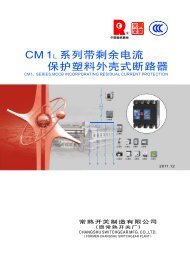
CW3G 系 列<br />
隔 离 开 关 ( AC,DC)<br />
CM3DC 系 列<br />
塑 料 外 壳 式 断 路 器<br />
CH 系 列 小 型 断 路 器<br />
CE1 系 列<br />
智 能 型 电 力 仪 表<br />
CI1 系 列<br />
远 程 智 能 I/O 模 块<br />
CN1DP-MP<br />
CN1DP-MD<br />
CN1DP-MC<br />
通 信 适 配 器<br />
CN1EG 以 太 网<br />
适 配 器<br />
FDM3<br />
短 消 息 通 知 模 块<br />
FWB1 温 度 报 警 模 块<br />
CSJ1 系 列 剩 余 电 流 式 电 气<br />
火 灾 监 控 探 测 器 ( 独 立 式 )<br />
CMSJ2 系 列 剩 余 电 流 式 电 气<br />
火 灾 监 控 探 测 器 ( 非 独 立 式 )<br />
CSX1 电 气 火 灾 监 控 设 备<br />
●Riyear-PowerNet 配 电 监 控 系 统<br />
●FCX3 智 能 配 电 监 控 器
优 秀 特 色<br />
获 得 国 际 认 可 的 CB 证 书<br />
具 有 体 积 小 、 分 断 高 、 带 隔 离 等 特 点<br />
额 定 极 限 短 路 分 断 能 力 :Icu:85kA~100kA<br />
额 定 运 行 短 路 分 断 能 力 :Ics:50kA~65kA<br />
额 定 短 时 耐 受 电 流 Icw(1s):5kA~10kA<br />
基 于 微 处 理 器 技 术 的 电 子 可 调 脱 扣 器 , 具 有 精 确 的 三 段 保 护 功 能<br />
短 路 保 护 具 有 后 备 保 护 , 由 后 备 磁 脱 扣 实 现 快 速 脱 扣 , 限 制 了 短 路 电 流 , 并 确 保 断 路 器<br />
可 靠 分 断<br />
基 于 Modbus-RTU 协 议 的 通 信 断 路 器 , 通 过 本 公 司 的 CN1DP 适 配 器 、CN1EG 以 太 网 适 配<br />
器 可 应 用 于 Modbus、Profibus、Devicenet、CAN 总 线 和 以 太 网 通 信 网 络 , 方 便 用 户 进 行 多<br />
种 协 议 的 应 用 管 理<br />
通 过 配 置 FDM3 短 消 息 通 知 模 块 , 可 实 现 断 路 器 故 障 脱 扣 或 报 警 信 息 无 线 监 视<br />
可 配 FWB1 温 度 报 警 模 块 , 实 现 连 接 点 在 线 超 温 报 警
目 录<br />
R<br />
概<br />
述<br />
1<br />
型 号 及 含 义 、 分 类<br />
2<br />
适 用 工 作 环 境 及 安 装 条 件<br />
3<br />
结 构 简 介<br />
3<br />
内 部 附 件 代 号<br />
6<br />
主 要 技 术 性 能 指 标<br />
7<br />
功 率 损 耗<br />
8<br />
智 能 型 脱 扣 器 特 性<br />
9<br />
外 形 尺 寸 及 安 装 尺 寸<br />
11<br />
断 路 器 安 装 安 全 间 隙<br />
19<br />
内 外 部 附 件<br />
20<br />
不 同 额 定 电 流 的 连 接 导 线 参 考 截 面<br />
25<br />
接 线 端 子 型 号<br />
25<br />
FWB1 温 度 报 警 模 块<br />
26<br />
通 信 功 能<br />
28<br />
订 货 须 知<br />
34
概<br />
述<br />
CM1 Z系 列 智 能 型 可 通 信 塑 壳 断 路 器 ( 以 下<br />
简 称 断 路 器 ), 是 本 公 司 采 用 先 进 的 CAD/CAM/<br />
CAE 设 计 、 制 造 技 术 , 研 制 、 开 发 的 新 型 断 路<br />
器 。 其 额 定 绝 缘 电 压 为 800V, 适 用 于 交 流 50Hz,<br />
额 定 工 作 电 压 400V, 额 定 电 流 至 800A 的 电 路 中 作<br />
不 频 繁 转 换 之 用 。 断 路 器 具 有 过 载 长 延 时 反 时<br />
限 、 短 路 短 延 时 反 时 限 、 短 路 短 延 时 定 时 限 、 短<br />
路 瞬 时 和 欠 电 压 保 护 功 能 , 能 保 护 线 路 和 电 源 设<br />
备 不 受 损 坏 。<br />
断 路 器 具 有 体 积 小 、 分 断 高 、 飞 弧 短 、 带<br />
隔 离 、 抗 振 动 等 特 点 。<br />
断 路 器 可 垂 直 安 装 ( 即 竖 装 ), 亦 可 水 平<br />
安 装 ( 即 横 装 )。<br />
断 路 器 不 可 倒 进 线 , 即 只 能 1、3、5 接 电<br />
源 线 ,2、4、6 接 负 载 线 。<br />
断 路 器 适 用 于 隔 离 , 符 号 表 示 为 “<br />
。<br />
”<br />
断 路 器 产 品 执 行 下 列 标 准 :<br />
IEC60947-1 及 GB14048.1-2006 总 则<br />
IEC60947-2 及 GB14048.2-2008 断 路 器<br />
及 附 录 F 带 电 子 过 电 流 保 护 断 路 器 的 附 加 试<br />
验<br />
断 路 器 获 国 家 强 制 性 产 品 认 证 “CCC” 标<br />
CM1z Series Moulded Case Circuit Breakers<br />
(hereafter simply referred to as breakers) are one of the new<br />
type breakers which have been developed by the company<br />
using international advanced design and manufaturing<br />
technology. The rated insulation voltage of the breakers is<br />
800V. In the circuit of AC50Hz, rated voltage 400V and<br />
rated currrent up to 800A, the breakers take the role of<br />
infrequent turn-on or turn-off. The breakers have overload<br />
long-delay<br />
inverse time, short-circuit short-delay<br />
inverse<br />
time, short-circuit short-delay<br />
definite time, short-circuit<br />
instantaneous and under-voltage protection performances so<br />
astoprotect thecircuit and powerappliancefromdamage.<br />
CM1z Series MCCBs have the characteristics of<br />
compact size,high-breakingcapacity, short arcoverdistance,<br />
isolation and anti-vibrationetc.<br />
The breakers can be installed vertically (upright) or<br />
horizontally (transverse).<br />
The breakers can’t be wired adversely. 1,3 and 5<br />
canonly be connectedwith powerline; 2,4 and6canonly be<br />
connectedwith loadline.<br />
The breaker has isolation function and its<br />
correspondingsymbolis shown as “ ”.<br />
The breakers comply with the demands of the<br />
followingstandards:<br />
IEC60947-1 andGB14048.1-2006 Generalrules<br />
IEC60947-2 andGB14048.2-2008 Circuit breakers<br />
And annex F: additional tests for circuit breakers<br />
withelectrical over-currentprotection.<br />
Thebreakershaveobtainedthe CCC mark ofCQC.<br />
志 。<br />
1
型 号 及 含 义 、 分 类<br />
型 号 及 其 含 义 如 下<br />
Typeand itsmeaning<br />
常 熟 开 关 制 造 有 限 公 司 ( 原 常 熟 开 关 厂 )<br />
Changshu SwitchgearManufacturingCo.,Ltd<br />
(FormerChangshuSwitchgearPlant)<br />
塑 料 外 壳 式 断 路 器<br />
MouldedCase CircuitBreaker<br />
设 计 代 号<br />
Design code<br />
智 能 型 可 通 信<br />
Intelligent communication<br />
CM1 Z - /<br />
*<br />
用 途 代 号<br />
Application Code<br />
附 件 代 号 ( 见 表 一 )<br />
Accessories Code<br />
(see table one)<br />
极 数 Polenumber<br />
带 电 动 操 作 机 构 为 “P”<br />
“P” if withmotoroperator<br />
额 定 极 限 短 路 分 断 能 力 级 别 代 号 为 H<br />
Rated ultimate short-circuitbreaking<br />
capacityclass<br />
壳 架 等 级 额 定 电 流 Framesizerated Current<br />
*<br />
注 : 配 电 用 无 代 号 , 保 护 电 动 机 用 2表 示 。 Note:No codeforpowerdistributiontype 2formotorprotectiontype<br />
按 产 品 极 数 分 三 极 与 四 极 。 四 极 产 品 中 性 极<br />
(N 极 ) 的 型 式 为 :N 极 过 电 流 保 护 电 流 、 时 间 参<br />
数 为 0( 即 中 性 极 无 保 护 ) 或 50% 或 100% 自 动 跟<br />
踪 相 极 电 流 、 时 间 整 定 值 , 且 N 极 与 相 极 一 起 合<br />
分 ( 先 合 后 分 )。<br />
按 额 定 电 流 分 :CM1Z-100 为 32(16~ 32)、<br />
63( 32~ 63)、100(63~ 100); CM1Z-225 为<br />
225( 100~ 225) ; CM1Z-400 为 400( 200~ 40<br />
0);CM1Z-630 为 630(400~630);CM1Z-800 为<br />
800(630~800)。<br />
按 接 线 方 式 分 为 板 前 接 线 、 板 后 接 线 、 插 入<br />
式 板 前 接 线 、 插 入 式 板 后 接 线 四 种 ;<br />
按 断 路 器 是 否 带 附 件 分 带 附 件 和 不 带 附 件 两<br />
种 :<br />
附 件 分 内 部 附 件 和 外 部 附 件 : 内 部 附 件 有 分<br />
励 脱 扣 器 、 欠 电 压 脱 扣 器 、 辅 助 触 头 、 报 警 触 头<br />
四 种 ; 外 部 附 件 有 电 动 操 作 机 构 、 断 路 器 控 制<br />
器 、 通 信 转 接 器 、 免 焊 连 接 器 、FWB1 温 度 报 警 模<br />
块 。<br />
Can be classified in terms of pole numbers into: three<br />
poles and four poles. The pattern of neutral phase (N) for<br />
four-pole breakers as follows: protective current of overcurrent<br />
in Npole, time parameter 0(namely, no protection<br />
forneutral phase)or 50%or100%automatic trackingphase<br />
current, settingvalue of time,and Npolecan be turned onor<br />
offtogether withphasepoles(firstturnedon,then off).<br />
Can be classified in terms of rated current into: 32<br />
(16~32), 63 (32~63), 100 (63~100) for CM1z-100; 225<br />
(100~225) for CM1z-225; 400 (200~400) for CM1z-400;<br />
630(400~630) for CM1z-630; 800(630~800)forCM1z-800.<br />
Thewiringmethod hasfiveways: front connected、rear<br />
connected、 plug-in front connected、 plug-in rear<br />
connectedand drawout connected.<br />
Can be classified intotwo types in terms of accessory:<br />
withorwithout accessories:<br />
The accessories can be classified into: internal and<br />
external accessories. The internal accessories have four<br />
kinds of shunt release, under-voltage release, auxiliary<br />
contact and alarm contact; the external accessories have<br />
power-driven operating mechanism, controller,<br />
communication adapter and welding-free adapter FWB1<br />
temperature alarmmodule.<br />
2
适 用 工 作 环 境 及 安 装 条 件<br />
安 装 地 点 的 海 拔 不 超 过 2000m;<br />
周 围 介 质 温 度 不 高 于 +40℃ 和 不 低 于 -5℃,<br />
且 24 小 时 的 平 均 值 不 超 过 35℃( 特 殊 订 货 除 外 );<br />
安 装 地 点 的 相 对 空 气 湿 度 在 最 高 温 度 为<br />
+40℃ 时 不 超 过 50%; 在 较 低 温 度 下 可 以 有 较 高 的<br />
相 对 湿 度 , 例 如 20 ℃ 时 达 90%, 对 由 于 温 度 变 化<br />
偶 尔 产 生 的 凝 露 应 采 取 特 殊 的 措 施 ;<br />
污 染 等 级 为 3 级 ;<br />
断 路 器 主 电 路 的 安 装 类 别 为 Ⅲ, 不 接 至 主<br />
电 路 的 辅 助 电 路 和 控 制 电 路 安 装 类 别 为 Ⅱ;<br />
断 路 器 适 用 于 电 磁 环 境 A;<br />
断 路 器 应 安 装 在 无 爆 炸 危 险 和 无 导 电 尘<br />
埃 、 无 足 以 腐 蚀 金 属 和 破 坏 绝 缘 的 地 方 ;<br />
安 装 在 没 有 雨 雪 侵 袭 的 地 方 ;<br />
断 路 器 应 按 产 品 的 使 用 说 明 书 安 装 和 连<br />
线 。<br />
The elevation of the installing site doesn’ texceed<br />
2000m;<br />
The ambient temperature is not above +40℃ and not<br />
below -5℃, and average temperature in 24 hours doesn’t<br />
exceed 35℃ (except specialorder);<br />
The relative humidity of the installing site doesn’ t<br />
exceed 50% at the maximum temperature of +40℃;at lower<br />
temperature, higher humidity would be permitted, for<br />
example, 90% at 20℃, given consideration of the dews due<br />
tothe temperature change, specialmeasures should be taken;<br />
Pollutiongrade:3;<br />
Installing categories: III for the main circuit, II for the<br />
auxiliary circuit without being connected with the main<br />
circuit andforcontrolcircuitalike;<br />
Be suitableinelectromagneticenvironment A;<br />
There must be not any explosive medium, and any gas<br />
which would corrode metal or any non-conducting dust<br />
which would destroythe insulation;<br />
Theplacewouldnot beinvaded byrain and snow;<br />
The circuit breaker should be installed and wired by<br />
followingits instruction.<br />
结 构 简 介<br />
SYNOPSIS OFSTRUCTURE<br />
断 路 器 外 观<br />
View ofthe circuitbreaker<br />
通 信 接 口<br />
CommunicationInterface<br />
通 信 指 示 灯<br />
Communicating IndicatorLight<br />
断 路 器 本 体<br />
BreakerMainBody<br />
脱 扣 按 钮<br />
Trip Button<br />
保 护 特 性 选 择<br />
ProtectivePerformance selection<br />
过 载 指 示<br />
Overload Indication<br />
预 报 警 指 示<br />
Pre-alarm Indication<br />
通 信 模 块<br />
CommunicationModular<br />
3
结 构 简 介<br />
SYNOPSIS OFSTRUCTURE<br />
智 能 型 脱 扣 器 保 护 特 性 参 数 的 设 定<br />
注 : 出 厂 时 已 设 置 , 用 户 一 般 不 需 调 整 。<br />
CM1Z-100,In=32A 智 能 型 脱 扣 器<br />
CM1Z-100,In=32AIntelligent Release<br />
Setting Protective Performance Parameters For<br />
IntelligentRelease<br />
Note:The Conventional settings are given at the time of<br />
shipping.Normally,itis not necessaryforcustomer toadjustthem.<br />
智 能 型 脱 扣 器 保 护 特 性 曲 线<br />
ProtectivePerformance CurveofIntelligent Release<br />
1 2<br />
3 4 5 7 6<br />
16<br />
TEST<br />
20<br />
60<br />
25<br />
80<br />
4 5 6 0.1<br />
3<br />
12<br />
2.5<br />
32<br />
100 2 12 1087<br />
6 7 8 10<br />
0.2 11<br />
0.06<br />
12 0.75 0.8 0.85 0.9<br />
0.95<br />
13<br />
0.3<br />
0.7<br />
4 16 14<br />
1<br />
I r1(A)<br />
t(s) 1<br />
I r2(XI r1)<br />
t(s) 2 I r3(XI r1)<br />
I ro(XI r1)<br />
t<br />
1<br />
2<br />
3<br />
4<br />
5<br />
o<br />
Ir1 Ir2<br />
Ir3<br />
I<br />
CM1Z<br />
-100,In=63A 智 能 型 脱 扣 器<br />
CM1Z-100,In=63AIntelligent Release<br />
智 能 型 脱 扣 器 保 护 特 性 曲 线<br />
ProtectivePerformance CurveofIntelligent Release<br />
1 2 3 4 5 7 6<br />
40 45<br />
36<br />
32<br />
63<br />
I r1(A)<br />
50<br />
55<br />
60<br />
TEST<br />
60<br />
4 5<br />
80<br />
6 0.1<br />
3<br />
0.2<br />
12<br />
2.5<br />
0.06<br />
100 2 12 10 87<br />
0.75 0.8 0.85 0.9<br />
0.95<br />
6 7 8 10 11<br />
12<br />
13<br />
0.3<br />
0.7<br />
4 16 14<br />
1<br />
t(s) 1 I r2(XI r1)<br />
t(s) 2 I r3(XI r1)<br />
I ro(XI r1)<br />
t<br />
1<br />
2<br />
3<br />
4<br />
5<br />
o<br />
Ir1 Ir2<br />
Ir3<br />
I<br />
CM1Z -100,In=100A 智 能 型 脱 扣 器<br />
智 能 型 脱 扣 器 保 护 特 性 曲 线<br />
CM1Z-100,In=100AIntelligent Release<br />
ProtectivePerformance CurveofIntelligent Release<br />
1 2 3 4 5 7 6<br />
70 75 80<br />
65 85<br />
63<br />
90<br />
100 95<br />
I r1(A)<br />
TEST<br />
60<br />
80<br />
4 5 6 0.1<br />
3<br />
0.2<br />
12 2.5<br />
100 2 12 10 87<br />
6 7 8 10 11<br />
0.06<br />
12 0.75 0.8 0.85 0.9<br />
0.95<br />
13<br />
0.3<br />
0.7<br />
4 16 14<br />
1<br />
t(s) 1 I r2(XI r1)<br />
t(s) 2 I r3(XI r1)<br />
I ro(XI r1)<br />
t<br />
1<br />
2<br />
3<br />
4<br />
5<br />
o<br />
Ir1 Ir2<br />
Ir3<br />
I<br />
CM1Z<br />
-225,In=225A 智 能 型 脱 扣 器<br />
CM1Z-225,In=225A IntelligentRelease<br />
智 能 型 脱 扣 器 保 护 特 性 曲 线<br />
ProtectivePerformance CurveofIntelligent Release<br />
7 1<br />
2 3 4 5 6<br />
TEST<br />
60<br />
4 5 6 0.1<br />
0.75 0.8 0.85 0.9<br />
0.95<br />
6 7 8 10 11<br />
125 140 160<br />
180<br />
80<br />
0.2<br />
200<br />
3<br />
0.06<br />
12<br />
100<br />
12<br />
2.5 13 0.7<br />
2 12 10 87<br />
225<br />
100<br />
0.3 4 16 14<br />
1<br />
I r1(A)<br />
t(s) 1 I r2(XI r1)<br />
t(s) 2 I r3(XI r1)<br />
I ro(XI r1)<br />
t<br />
1<br />
2<br />
3<br />
4<br />
5<br />
o<br />
Ir1 Ir2<br />
Ir3<br />
I<br />
4
结 构 简 介<br />
SYNOPSIS OFSTRUCTURE<br />
CM1Z -400,In=400A 智 能 型 脱 扣 器<br />
智 能 型 脱 扣 器 保 护 特 性 曲 线<br />
CM1Z-400,In=400AIntelligent Release<br />
7 1 2 3 4 5<br />
6<br />
ProtectivePerformance CurveofIntelligent Release<br />
TEST<br />
250 280 315 60<br />
4 5 6 0.1<br />
0.75 0.8 0.85 0.9 0.95<br />
6 7 8 9<br />
100<br />
0.2<br />
10<br />
225 350<br />
3<br />
0.06<br />
2.5 2<br />
0.7<br />
12 10 87<br />
11<br />
12<br />
200<br />
400<br />
150 0.3 4 14 13 12<br />
1<br />
I r1(A)<br />
t(s) 1 I r2(XI r1)<br />
t(s) 2 I r3(XI r1)<br />
I ro(XI r1)<br />
t<br />
1<br />
2<br />
3<br />
4<br />
5<br />
o<br />
Ir1 Ir2<br />
Ir3<br />
I<br />
CM1Z -630,In=630A 智 能 型 脱 扣 器<br />
智 能 型 脱 扣 器 保 护 特 性 曲 线<br />
CM1Z-630,In=630A IntelligentRelease<br />
7 1 2 3 4 5 6<br />
ProtectivePerformance CurveofIntelligent Release<br />
TEST<br />
460 480 500<br />
440 530<br />
420 560 12<br />
400 630<br />
600<br />
I r1(A)<br />
60<br />
5<br />
0.1<br />
100<br />
4 6<br />
3<br />
0.2<br />
0.75 0.8 0.85 0.9<br />
0.06<br />
0.95<br />
2.5 2<br />
0.7<br />
12 10 87<br />
7 8 9 10<br />
11<br />
6<br />
150<br />
0.3 4 14 13 12<br />
1<br />
t(s) 1 I r2(XI r1)<br />
t(s) 2 I r3(XI r1)<br />
I ro(XI r1)<br />
t<br />
1<br />
2<br />
3<br />
4<br />
5<br />
o<br />
Ir1 Ir2<br />
Ir3<br />
I<br />
CM1Z<br />
-800,In=800A 智 能 型 脱 扣 器<br />
CM1Z-800,In=800AIntelligentRelease<br />
7 1 2 3 4 5<br />
6<br />
智 能 型 脱 扣 器 保 护 特 性 曲 线<br />
ProtectivePerformance Curve ofIntelligent Release<br />
TEST<br />
680 700 720 60 3.5 4 5 0.1<br />
660<br />
100<br />
0.75 0.8 0.85 740<br />
0.2<br />
0.9<br />
3<br />
0.95<br />
640<br />
12<br />
0.06<br />
2.5 2<br />
0.7<br />
10 8 76<br />
6 7 8 9<br />
760 5<br />
800 780<br />
150<br />
0.3 4 12 11<br />
10<br />
630<br />
1<br />
I r1(A)<br />
t(s) 1 I r2(XI r1)<br />
t(s) 2 I r3(XI r1)<br />
I ro(XI r1)<br />
t<br />
1<br />
2<br />
3<br />
4<br />
5<br />
o<br />
Ir1 Ir2<br />
Ir3<br />
I<br />
保 护 :<br />
1- 过 载 长 延 时 动 作 电 流 Ir1 调 整 , 根 据 断 路 器 不 同 的 额 定<br />
电 流 , 可 从 4 档 到 10 档 进 行 调 整 ;<br />
2- 长 延 时 动 作 时 间 t1 调 整 , 可 进 行 4 档 调 整 ;<br />
3- 短 路 短 延 时 动 作 电 流 Ir2 调 整 , 可 进 行 10 档 调 整 ;<br />
4- 短 延 时 动 作 时 间 t2 调 整 , 可 进 行 4 档 调 整 ;<br />
5- 短 路 瞬 时 动 作 电 流 Ir3 调 整 , 可 进 行 8 档 、9 档 或 10 档 调<br />
整 ;<br />
6- 预 报 警 动 作 电 流 Ir0 调 整 , 可 进 行 7 档 调 整 。<br />
Protection<br />
1-For the adjustment of overloadlong-timedelayactingcurrent Ir1,<br />
according to different rated current,this knob canbe adjusted from 4<br />
stops to10 stops;<br />
2-For the adjustment of long-time acting time t1,this knob can be<br />
adjusted4stops;<br />
3-For the adjustment of short-circuit short-time delay acting current<br />
Ir2,this knobcanbeadjusted10stops;<br />
4-For the adjustment of short-time acting time t2,this knobcan be<br />
adjusted4stops;<br />
5-Fortheadjustmentfoshort-circuitinstantaneousactingcurrent Ir3,this<br />
knobcanbeadjusted8stops,9stops or10stops;<br />
6-For the adjustment of pre-alarm acting current Ir0,thisknob can be<br />
adjusted7stops;<br />
其 它 功 能 :<br />
OtherFunctions<br />
7- 测 试 端 , 用 于 检 测 智 能 型 脱 扣 器 当 前 整 定 值 。 7-Testterminal,forthetestingofpresentvaluesofintelligent<br />
release.<br />
5
内 部 附 件 代 号<br />
INTERNALACCESSORIES CODE<br />
附 件 代 号 见 表 一<br />
AccessoriesCode SeeTable1<br />
左 面 安 装<br />
Leftmounting<br />
手 柄<br />
Hardle<br />
右 面 安 装<br />
Rightmounting<br />
报 警 触 头<br />
辅 助 触 头<br />
分 励 脱 扣 器<br />
欠 电 压 脱 扣 器<br />
引 线 方 向<br />
Alarm Contact<br />
AuxiliaryContact<br />
ShuntRelease<br />
Under-voltageRealease<br />
Lead Direction<br />
表 一 Table 1<br />
型 号<br />
Code<br />
CM1z-100 CM1z-225 CM1z-400 CM1z-630 CM1z-800<br />
附 件<br />
代 号<br />
Accessories<br />
Code<br />
附 件 名 称<br />
Accessories name<br />
极 数<br />
Polenumber<br />
3 4 3 4 3 4 3 4 3 4<br />
308<br />
报 警 触 头<br />
Alarmcontact<br />
310<br />
分 励 脱 扣 器<br />
ShuntRelease<br />
320<br />
辅 助 触 头<br />
Auxiliary Contact<br />
330<br />
欠 电 压 脱 扣 器<br />
Under-voltageRelease<br />
328<br />
辅 助 触 头 报 警 触 头<br />
Auxiliary Contact<br />
Alarm Contact<br />
注 :300: 表 示 不 带 表 中 附 件 的 断 路 器 ;<br />
Note:300 forthe circuit breakerswithoutaccessorieslisted intable;<br />
6
主 要 技 术 性 能 指 标<br />
MAIN TECHNICAL PERFORMANCE INDER<br />
断 路 器 主 要 技 术 性 能 指 标 见 表 二<br />
TheCircuitBreaker MainTechnical Performance InderSeeTable2<br />
表 二 Table 2<br />
型 号 Type<br />
壳 架 电 流 Inm (A)<br />
FramesizeCurrent<br />
额 定 电 流 In (A)<br />
Rated Current<br />
整 定 电 流 Ir 1 (A)<br />
Settingcurrent<br />
极 数<br />
Pole Number<br />
额 定 绝 缘 电 压 Ui (V)<br />
Rated Insulation Voltage<br />
额 定 工 作 电 压 Ue (V)<br />
RatedoperationalVoltage<br />
额 定 冲 击 耐 受 电 压 Uimp (V)<br />
Rated impulse withstand Voltage<br />
额 定 极 限 短 路 分 断 能 力 Icu(kA)<br />
Rated ultionate short-circuit Breaking capacity<br />
额 定 运 行 短 路 分 断 能 力 Ics(kA)<br />
Ratedsevice short-circuitBreakingcapacity<br />
额 定 短 时 耐 受 电 流 Icw(kA)/1s<br />
Rated Short-time withstand current<br />
机 械 *<br />
寿 命<br />
( 次 times)<br />
Mechanical<br />
durability<br />
使 用 类 别<br />
Utilization Category<br />
飞 弧 距 离 (mm)<br />
Arc-over Distance(mm)<br />
电 气 寿 命 *( 次 times)<br />
Electricaldurabilty<br />
免 维 护<br />
Freemaintenance<br />
维 护<br />
Maintenance<br />
CM1Z-100<br />
CM1Z-225<br />
CM1Z-400<br />
CM1Z-630<br />
CM1Z-800<br />
100 225<br />
32,63,100<br />
32(16~32)<br />
63(32~63)<br />
100(63~100)<br />
3 4<br />
225<br />
400<br />
400<br />
630<br />
630<br />
800<br />
800<br />
225(100~225) 400(200~400) 630(400~630) 800(630~800)<br />
3 4 3 4 3 4 3 4<br />
800<br />
400<br />
8000<br />
85 85 100 100 100<br />
50 50 65<br />
65 65<br />
5 8 10<br />
A A B B B<br />
8000<br />
20000<br />
40000<br />
≯50(0)**<br />
8000<br />
20000<br />
40000<br />
≯100(0)**<br />
7500<br />
10000<br />
20000<br />
7500<br />
10000<br />
20000<br />
≯100<br />
7500<br />
10000<br />
20000<br />
W<br />
欠 电 压 脱 扣 器<br />
Under-voltage Release<br />
分 励 脱 扣 器<br />
ShuntRealease<br />
辅 助 触 头<br />
Auxiliary Contact<br />
报 警 触 头<br />
Alarm Contact<br />
电 动 操 作 机 构<br />
Motor operator<br />
H<br />
W 92 122 107 142 150 198 210 280 210 280<br />
L 150 165 257 280 280<br />
H 92 90 106.5 115.5 115.5<br />
○<br />
○<br />
○<br />
○<br />
○<br />
○<br />
○ ○ ○ ○<br />
○ ○ ○ ○<br />
注 :CM1Z-800 无 电 动 机 保 护 型 。<br />
Note:CM1z-800withoutthe typeofelectromotor protection.<br />
* 注 : 根 据 GB14048.1-2006, 术 语 “ 寿 命 ” 表 示 电 器 在 修 理 或 更 换 部 件 前 完 成 的 操 作 循 环 次 数 的 概 率 。<br />
*Note:for GB14048.1-2006,the term"durability"expresses the expectancy ofthe numberof operating cycleswhich canbe performed<br />
by theequipment before repairor replacementof parts<br />
** 注 :CM1Z<br />
-100、225、400 分 别 选 装 高 为 6mm、7.5mm、9.3mm 的 零 飞 弧 罩 , 实 现 零 飞 弧 。<br />
**note:canbe zeroarcventingby installing arccover of6mm, 7.5mm,9.3mm for CM1Z-100/225/400.<br />
○<br />
○<br />
○<br />
○<br />
○<br />
○<br />
○<br />
○<br />
○<br />
○<br />
○<br />
7
功 率 损 耗<br />
POWER LOSS<br />
功 率 损 耗 见 表 三<br />
Power LossSee Table 3<br />
表 三 Table 3<br />
三 极 / 四 极 总 功 率 损 耗 (W)<br />
TotalPowerLossof Three /four poles<br />
型 号<br />
Code<br />
通 电 电 流 (A)<br />
Energized<br />
板 前 、 板 后 接 线<br />
Front/rear connected<br />
插 入 式 板 前 接 线<br />
Plug-in front<br />
connected<br />
插 入 式 板 后 接 线<br />
Plug-in rear<br />
connected<br />
抽 出 式 板 后 接 线<br />
Draw-outconnected<br />
CM1z-100<br />
100<br />
12 12<br />
12.2<br />
CM1z-225<br />
225 24.3 24.3<br />
24.5<br />
CM1z-400<br />
400<br />
52.8<br />
52.8 53.2 73<br />
CM1z-630<br />
630<br />
71.4<br />
71.4<br />
71.6 91.4<br />
CM1z-800<br />
800<br />
115.2<br />
115.2<br />
115.4 135.4<br />
8
智 能 型 脱 扣 器 特 性<br />
Intelligent Release Feature<br />
脱 扣 器 特 性<br />
ReleaseFeature<br />
断 路 器 内 装 按 有 效 值 采 样 的 电 流 传 感 器 。 断 路 器 具 有 过 载 长 延 时 反 时 限 、 短 路 短 延 时 反 时 限 、<br />
短 路 短 延 时 定 时 限 、 短 路 瞬 时 动 作 等 保 护 功 能 , 可 由 用 户 自 行 设 定 组 成 所 需 的 保 护 特 性 。 脱 扣 器 特<br />
性 见 下 图 。<br />
The breakerforwhich the currentsensingmeans arestatedto ber.m.s. responside.ithas theprotectionfeatures<br />
of long-delay overload inverse time,short-circuit short-delay inverse time,short-ciruit short-delay definite<br />
time,instantaneousshort-circuit,etc. It can also adjusted to meet the customers' needs by themselves. See the<br />
followingchartof releasefeature.<br />
4h<br />
2h<br />
动<br />
作<br />
时<br />
间<br />
1h<br />
30min<br />
20min<br />
14min<br />
10min<br />
6min<br />
4min<br />
2min<br />
1min<br />
30sec<br />
20sec<br />
10sec<br />
5sec<br />
2sec<br />
150s<br />
100s<br />
80s<br />
60s<br />
12s<br />
长 延 时 动 作 电 流 Ir1<br />
长 延 时 动 作 时 间 t 1±20%<br />
(12-150)s<br />
when long-delay operatingcurrentIr 1,<br />
long-delay operating timet 1±20%<br />
(12-150)s<br />
短 延 时 动 作 电 流 Ir 2±10%<br />
Short-delay operating currentIr 2±10%<br />
(2-12)Ir<br />
1<br />
1sec<br />
0.5sec<br />
短 延 时 动 作 时 间 t2<br />
Short-delayoperating<br />
time<br />
0.2sec<br />
0.1sec<br />
0.05sec<br />
0.02sec<br />
0.01sec<br />
瞬 时 动 作 电 流 Ir<br />
3<br />
Instantaneous operating currentIr3<br />
(4-16)Ir 1±15%<br />
最 大 瞬 时 动 作 时 间<br />
Max instantaneous operating time<br />
0.3±0.06s<br />
0.2±0.04s<br />
0.1±0.03s<br />
0.06±0.02s<br />
0.6 0.7<br />
1<br />
1.3<br />
2<br />
3<br />
4<br />
5<br />
6<br />
7<br />
10 12<br />
15<br />
20<br />
30<br />
40<br />
电 流 (×Ir 1)(A)<br />
Current<br />
9
智 能 型 脱 扣 器 特 性<br />
Intelligent Release Feature<br />
长 延 时 过 电 流 保 护 反 时 限 动 作 特 性 见 表 四<br />
Long-timedelayover-currentprotectioninverseoperating<br />
characteristics see table4<br />
表 四 Table 4<br />
电 流<br />
Current<br />
动 作 时 间 Operating Time<br />
1.05Ir1<br />
2 小 时 内 不 动 作 No operating within 2h<br />
配<br />
电<br />
型<br />
1.3Ir1<br />
2Ir1<br />
整 定 时 间 t(s) 1<br />
Setting time<br />
≤1h 动 作 Operating<br />
Inm=100、225A<br />
Inm=400、630、800A<br />
12 60 80 100 12 60 100 150<br />
1.05Ir1<br />
2 小 时 内 不 动 作 Nooperatingwithin2h<br />
电<br />
动<br />
机<br />
保<br />
护<br />
型<br />
1.2Ir1<br />
1.5Ir1<br />
2Ir1<br />
7.2Ir1<br />
脱 扣 级 别 Tripclass<br />
动 作 时 间 T(s) 1<br />
Operating time<br />
整 定 时 间 t(s) 1<br />
Setting time<br />
动 作 时 间 T(s) 1<br />
Operating time<br />
≤1h 动 作<br />
Inm=100、225A<br />
Operating<br />
Inm=400、630A<br />
21.3 107 142 178 21.3 107 178 267<br />
12 60 80 100 12 60 100 150<br />
0.93 4.63 6.17 7.72 0.93 4.63 7.72 11.6<br />
- 10A 10 20 - 10 20 30<br />
2 2<br />
注 :1. 动 作 时 间 符 合 IT=(2Ir 1 1 )t 1 (1.2Ir1≤I
外 形 尺 寸 及 安 装 尺 寸<br />
Outline Dimersions and Installation Dimensions<br />
CM1Z-100 板 前 接 线 ( 三 极 、 四 极 )<br />
X-X、Y-Y 为 三 极 断 路 器 中 心<br />
X-XY-Yasthe center ofthree polesbreaker<br />
Frontconnected(three、four poles)<br />
4-φ4.5<br />
Y<br />
30<br />
相 间 隔 板<br />
M8<br />
17.5<br />
Interphasebarrier<br />
28.5<br />
110<br />
92<br />
Y<br />
22<br />
N<br />
X<br />
X<br />
X<br />
X<br />
m<br />
21.9<br />
20.2<br />
4<br />
10<br />
4-φ4.5<br />
60<br />
92<br />
90<br />
122<br />
欠 电 压 脱 扣 器 厚 度 :<br />
C 型 m=21<br />
Thewidthof under-voltagerelease<br />
Type m=21<br />
Y<br />
30<br />
Y<br />
板 前 接 线 安 装 板 开 孔 尺 寸<br />
Mountingplatecutoutdimensionsof frontconnected<br />
CM1Z-100 板 后 接 线 ( 三 极 、 四 极 )<br />
X-X、Y-Y 为 三 极 断 路 器 中 心<br />
Rearconnected (three、fourpoles)<br />
X-X、Y-Yas thecenterofthree polesbreaker<br />
A<br />
10<br />
35<br />
A 向 direction<br />
Y<br />
93<br />
53<br />
60<br />
72( 三 极 )<br />
102( 四 极 )<br />
threepoles<br />
fourpoles<br />
X<br />
X<br />
φ5.5<br />
φ22<br />
Y<br />
板 后 接 线 安 装 板 开 孔 尺 寸<br />
Mountingplatecutout dimensionsof rearconnected<br />
11
外 形 尺 寸 及 安 装 尺 寸 Outline Dimersions and Installation Dimensions<br />
CM1Z-100 插 入 式 板 前 接 线 ( 三 极 )<br />
X-X、Y-Y 为 三 极 断 路 器 中 心<br />
Plug-in front connected(threepoles)<br />
X-X、Y-Yas thecenterofthree polesbreaker<br />
Y<br />
60<br />
94(min)<br />
60<br />
X<br />
X<br />
4-Φ6.5<br />
3<br />
24<br />
36<br />
Y<br />
插 入 式 板 前 接 线 安 装 板 开 孔 尺 寸<br />
Mounting platecutout dimensionsof plug-in frontconnected<br />
CM1Z-100 插 入 式 板 后 接 线 ( 三 极 、 四 极 )<br />
X-X、Y-Y 为 三 极 断 路 器 中 心<br />
Plug-in rearconnected(three、four poles)<br />
X-X、Y-Yas thecenterofthree polesbreaker<br />
76<br />
64<br />
50<br />
Y<br />
94(min)( 三 极 )<br />
three poles<br />
X<br />
60( 三 极 ) threepoles<br />
90( 四 极 ) fourpoles<br />
φ6.5<br />
X<br />
17.5 M8<br />
125(min)( 四 极 )<br />
fourpoles<br />
Y<br />
插 入 式 板 后 接 线 安 装 板 开 孔 尺 寸<br />
Mounting platecutout dimensionsof plug-inrear connected<br />
12
外 形 尺 寸 及 安 装 尺 寸 Outline Dimersions and Installation Dimensions<br />
CM1Z-225 板 前 接 线 ( 三 极 、 四 极 )<br />
X-X、Y-Y 为 三 极 断 路 器 中 心<br />
Frontconnected(three、fourpoles)<br />
X-X Y-Y asthe centerof three polesbreaker<br />
20×<br />
5<br />
Y<br />
35<br />
相 间 隔 板 Interphasebarrier<br />
110<br />
连 接 排 ( 选 购 件 )<br />
Connectingbar(optional)<br />
24<br />
90<br />
Y<br />
22<br />
N<br />
X<br />
X<br />
X<br />
X<br />
m 42.8<br />
4-φ5<br />
20.2<br />
4<br />
5<br />
4-φ4.5<br />
M8<br />
70<br />
107<br />
105<br />
欠 电 压 脱 扣 器 厚 度 :<br />
C 型 m=21<br />
The widthof under-voltagerelease<br />
Type m=21<br />
Y<br />
142<br />
板 前 接 线 安 装 板 开 孔 尺 寸<br />
Mounting platecutout dimensionsoffront connected<br />
35<br />
Y<br />
CM1Z-225 板 后 接 线 ( 三 极 、 四 极 )<br />
X-X、Y-Y 为 三 极 断 路 器 中 心<br />
Rear connected (three、four poles)<br />
X-X、Y-Y asthecenterofthreepolesbreaker<br />
A<br />
10<br />
35<br />
A 向 direction<br />
100<br />
Y<br />
55<br />
13<br />
87( 三 极 )<br />
122( 四 极 )<br />
three poles<br />
fourpoles<br />
X<br />
X<br />
φ5.5<br />
φ24<br />
M8<br />
70<br />
Y<br />
板 后 接 线 安 装 板 开 孔 尺 寸<br />
Mounting plate cutout dimensions of rear connected<br />
13
外 形 尺 寸 及 安 装 尺 寸 Outline Dimersions and Installation Dimensions<br />
CM1Z-225 插 入 式 板 前 接 线 ( 三 极 )<br />
X-X、Y-Y 为 三 极 断 路 器 中 心<br />
Plug-in front connected(threepoles)<br />
X-X、Y-Y as thecenterofthree polesbreaker<br />
Y<br />
70<br />
110(min)<br />
70<br />
4-Φ6.5<br />
X<br />
X<br />
4<br />
24<br />
41<br />
Y<br />
插 入 式 板 前 接 线 安 装 板 开 孔 尺 寸<br />
Mounting platecutout dimensionsofplug-in front connected<br />
CM1Z-225 插 入 式 板 后 接 线 ( 三 极 、 四 极 )<br />
X-X、Y-Y 为 三 极 断 路 器 中 心<br />
Plug-in rear connected(three、four poles)<br />
X-X、Y-Yas the center ofthree polesbreaker<br />
86.5<br />
71.5<br />
50<br />
Y<br />
110(min)( 三 极 )<br />
threepoles<br />
X<br />
70( 三 极 ) threepoles<br />
105( 四 极 ) fourpoles<br />
φ6.5<br />
X<br />
17.5<br />
M8<br />
145(min)( 四 极 )<br />
fourpoles<br />
Y<br />
插 入 式 板 后 接 线 安 装 板 开 孔 尺 寸<br />
Mounting platecutout dimensionsofplug-in rearconnected<br />
14
外 形 尺 寸 及 安 装 尺 寸 Outline Dimersions and Installation Dimensions<br />
CM1Z-400 板 前 接 线 ( 三 极 、 四 极 )<br />
X-X、Y-Y 为 三 极 断 路 器 中 心<br />
3.5<br />
Frontconnected(three、fourpoles)<br />
X-X Y-Y asthe centerofthree polesbreaker<br />
连 接 排 ( 选 购 件 )<br />
Connecting bar(optional)<br />
φ13<br />
Y<br />
44<br />
相 间 隔 板 Interphasebarrier<br />
30×<br />
8<br />
M10<br />
38<br />
Y<br />
4-φ7<br />
65<br />
N<br />
X X<br />
X X<br />
m<br />
57<br />
20.2<br />
3.5<br />
4-φ7<br />
11<br />
96<br />
150<br />
144<br />
138<br />
186<br />
198<br />
Y<br />
106.5<br />
146.5<br />
4.5<br />
板 前 接 线 安 装 板 开 孔 尺 寸<br />
Mounting platecutout dimensionsof front connected<br />
44<br />
Y<br />
欠 电 压 脱 扣 器 厚 度 :<br />
C 型 m=21<br />
Thewidthof under-voltagerelease<br />
Typem=21<br />
CM1Z-400 板 后 接 线 ( 三 极 、 四 极 )<br />
X-X、Y-Y 为 三 极 断 路 器 中 心<br />
Rear connected(three、fourpoles)<br />
X-X、Y-Yasthecenterofthreepolesbreaker<br />
A<br />
12<br />
37<br />
A 向 direction<br />
Y<br />
108.5<br />
48.5<br />
124( 三 极 )<br />
172( 四 极 )<br />
threepoles<br />
fourpoles<br />
X<br />
X<br />
φ10.5<br />
φ6.5<br />
φ32<br />
M10<br />
96<br />
144<br />
板 后 接 线 安 装 板 开 孔 尺 寸<br />
Mountingplatecutoutdimensionsof rearconnected<br />
Y<br />
15
外 形 尺 寸 及 安 装 尺 寸 Outline Dimersions and Installation Dimensions<br />
CM1Z-400 插 入 式 板 前 接 线 ( 三 极 )<br />
X-X、Y-Y 为 三 极 断 路 器 中 心<br />
Plug-infrontconnected(three poles)<br />
X-X、Y-Y asthecenterofthree polesbreaker<br />
Y<br />
118<br />
X<br />
152(min)<br />
60<br />
4-Φ8.5<br />
X<br />
6<br />
38.3<br />
52<br />
Y<br />
插 入 式 板 前 接 线 安 装 板 开 孔 尺 寸<br />
Mounting plate cutout dimensions ofplug-in front connected<br />
CM1Z-400 插 入 式 板 后 接 线 ( 三 极 、 四 极 )<br />
X-X、Y-Y 为 三 极 断 路 器 中 心<br />
Plug-inrearconnected(three、four poles)<br />
X-X、Y-Y asthecenterofthree polesbreaker<br />
106.5<br />
83.5<br />
60<br />
Y<br />
152(min)( 三 极 )<br />
threepoles<br />
X<br />
60( 三 极 )<br />
108( 四 极 )<br />
φ8.5<br />
threepoles<br />
fourpoles<br />
X<br />
21<br />
M10<br />
200(min)( 四 极 )<br />
fourpoles<br />
插 入 式 板 后 接 线 安 装 板 开 孔 尺 寸<br />
Mounting plate cutout dimensionsof plug-inrearconnected<br />
Y<br />
16
外 形 尺 寸 及 安 装 尺 寸 Outline Dimersions and Installation Dimensions<br />
CM1Z-400 抽 出 式 接 线 ( 三 极 、 四 极 )<br />
X-X、Y-Y 为 三 极 断 路 器 中 心<br />
Draw-out connected(three、fourploes)<br />
X-XY-Y centerforthree poles breaker<br />
Y<br />
Φ11<br />
板 后 接 线<br />
Rear connected<br />
板 前 接 线<br />
Frontconnected<br />
Y<br />
96( 三 极 three poles)<br />
Φ6.5<br />
ON<br />
N<br />
X<br />
X<br />
X<br />
X<br />
OFF<br />
77<br />
48 48 48<br />
Y<br />
W<br />
极 数<br />
Pole<br />
W<br />
三 极<br />
Three poles 223<br />
四 极<br />
Fourpoles 271<br />
17.5<br />
221<br />
144( 四 极 fourpoles)<br />
Y<br />
抽 出 式 接 线 安 装 开 孔 尺 寸<br />
mountingplatecutout dimensions of<br />
draw-outconnected<br />
CM1Z-630<br />
CM1Z-800 板 前 接 线 ( 三 极 、 四 极 )<br />
X-X、Y-Y 为 三 极 断 路 器 中 心<br />
Frontconnected(three、fourpoles)<br />
X-XY-Yasthe center ofthreepolesbreaker<br />
连 接 排 ( 选 购 件 )<br />
Connecting bar(optional)<br />
φ14<br />
M12<br />
Y<br />
70<br />
相 间 隔 板 Interphasebarrier<br />
44×<br />
a<br />
45.3<br />
Y<br />
70<br />
4-φ7<br />
X<br />
m 4-φ7<br />
53<br />
66<br />
140<br />
210<br />
210<br />
198<br />
268<br />
280<br />
Y<br />
115.5<br />
欠 电 压 脱 扣 器 厚 度 :<br />
C 型 m=0 CM1Z-630<br />
The widthofunder-voltage release<br />
Typem=0<br />
N<br />
20.2<br />
X<br />
46<br />
4.5<br />
4.5<br />
155<br />
8<br />
型 号<br />
Type<br />
CM1Z-800<br />
X<br />
板 前 接 线 安 装 板 开 孔 尺 寸<br />
Mounting platecutout dimensionsoffront connected<br />
a(mm)<br />
7<br />
10<br />
Y<br />
X<br />
17
外 形 尺 寸 及 安 装 尺 寸 Outline Dimersions and Installation Dimensions<br />
CM1Z-630<br />
CM1Z-800 板 后 接 线 ( 三 极 、 四 极 )<br />
X-X、Y-Y 为 三 极 断 路 器 中 心<br />
A<br />
12<br />
37<br />
A 向 direction<br />
Rearconnected(three poles)<br />
X-X、Y-Yas thecenterofthree polesbreaker<br />
84<br />
62<br />
Y<br />
140<br />
φ7<br />
X<br />
178( 三 极 )<br />
248( 四 极 )<br />
threepoles<br />
210<br />
φ48<br />
fourpoles<br />
X<br />
M12<br />
插 入 式 板 前 接 线 安 装 板 开 孔 尺 寸<br />
Mounting platecutout dimensionsof rear connected<br />
Y<br />
CM1Z-630<br />
CM1Z-800 插 入 式 板 后 接 线 ( 三 极 、 四 极 )<br />
X-X、Y-Y 为 三 极 断 路 器 中 心<br />
Plug-in rearconnected(three、four poles)<br />
X-X、Y-Yas thecenterofthree polesbreaker<br />
97<br />
61<br />
148<br />
M12<br />
36<br />
M12<br />
Y<br />
213(min)( 三 极 )<br />
threepoles<br />
16<br />
18<br />
X<br />
140( 三 极 ) threepoles<br />
210( 四 极 ) fourpoles<br />
φ10<br />
X<br />
283(min)( 四 极 )<br />
Y<br />
插 入 式 板 后 接 线 安 装 板 开 孔 尺 寸<br />
Mountingplatecutoutdimensionsof plug-in rear connected<br />
18
外 形 尺 寸 及 安 装 尺 寸 Outline Dimersions and Installation Dimensions<br />
CM1Z-630<br />
CM1Z-800 抽 出 式 接 线 ( 三 极 、 四 极 )draw-out connected (three、four poles)<br />
X-X、Y-Y 为 三 极 断 路 器 中 心 X-XY-Ycenterforthree poles breaker<br />
Y<br />
Φ13<br />
板 后 接 线<br />
Rear connected<br />
板 前 接 线<br />
Frontconnected<br />
Y<br />
140( 三 极 threepoles)<br />
Φ6.5<br />
ON<br />
N<br />
X<br />
X<br />
X<br />
X<br />
OFF<br />
73<br />
210( 四 极 four poles)<br />
70 70 70<br />
Y<br />
W<br />
极 数<br />
Pole<br />
三 极<br />
Three poles<br />
四 极<br />
Four poles<br />
W<br />
289<br />
359<br />
26<br />
210<br />
Y<br />
抽 出 式 接 线 安 装 开 孔 尺 寸<br />
mountingplatecutoutdimensions of<br />
draw-outconnected<br />
断 路 器 安 装 安 全 间 隙<br />
C<br />
型 号<br />
Type<br />
CM1z-100<br />
CM1z-225<br />
CM1z-400<br />
CM1z-630、800 100<br />
E<br />
C<br />
不 需 零 飞 弧 罩<br />
without zero arcventingcover<br />
50<br />
50<br />
100<br />
A: 到 导 电 回 路 ( 包 括 无 遮 挡 物 或 有 接 地 金 属 )<br />
B: 断 路 器 端 子 到 底 墙<br />
C: 断 路 器 侧 部 到 侧 墙 ( 包 括 无 遮 挡 物 或 有 接 地 金 属 )<br />
D: 到 非 导 电 部 件<br />
注 :E 为 相 间 隔 板 , 必 须 安 装 。<br />
A:To conductivecircuit(including without shetter orwith earthed metals )<br />
B:The terminals of thecircuitbreakerto the bottom wall<br />
C: The side case of the circuit (breaker to the side wall (including withoutshelteror<br />
with earthed metals)<br />
D:To non-conductive units<br />
Note:E, the interphase barrier,should beinstalled<br />
A<br />
19<br />
带 零 飞 弧 罩<br />
withzeroarcventingcover<br />
注 :CM1Z-100、255、400 必 须 安 装 相 间 隔 板 或 零 飞 弧 罩 , 可 选 择 。<br />
The interphasebarriers orzeroarcventingcovers shouldbe installed,may be selected.<br />
25<br />
25<br />
25<br />
单 位 :mm<br />
Measurement<br />
B C D<br />
25<br />
25<br />
25<br />
25<br />
25<br />
25<br />
25<br />
25<br />
25<br />
25<br />
25<br />
25
内 外 部 附 件<br />
Internal and ExternalAccessories<br />
1、 断 路 器 的 内 部 附 件<br />
根 据 用 户 需 要 断 路 器 附 件 可 直 接 导 线 引 出 ,<br />
或 加 装 接 线 端 子 排 ( 加 装 接 线 端 子 排 , 用 户 订<br />
货 时 注 明 )。<br />
欠 电 压 脱 扣 器 , 符 号 ○ Under-voltagerelease<br />
C 型 :AC50Hz 230V 或 400V。<br />
外 挂 欠 电 压 模 块 接 线 图<br />
( 虚 框 内 为 断 路 器 内 部 附 件 接 线 图 )<br />
1、Internaland External Accessories<br />
Intermsofusers’ requirements,accessories could<br />
lead out by direct wire or by line wiring terminals<br />
additionally equipped (please mark out in case of<br />
makingorder)<br />
CType:<br />
Wiring diagram of the under-voltage module<br />
connected externally (Wiring diagram of internal<br />
accessoriesareindicatedin thedotted square)<br />
C 型<br />
X<br />
P 1<br />
P2<br />
电 源 输 入<br />
Power Supply<br />
欠 电 压 脱 扣 器 型 号<br />
Under-voltagerelease type<br />
配 用 断 路 器 Fittingbreaker<br />
安 装 位 置<br />
Mounting position<br />
欠 电 压 脱 扣 器 功 率 (VA)<br />
undervoltage releasepower<br />
AC230V<br />
AC400V<br />
QTCM1L<br />
-100Z<br />
CM1Z<br />
-100 三 极 、 四 极 three/fourpoles<br />
左 面 left<br />
2.6<br />
3.3<br />
QTCM1E<br />
-225Z<br />
CM1Z<br />
-225 三 极 、 四 极 three/fourpoles<br />
左 面 left<br />
3.8<br />
3.3<br />
QTCM1L<br />
-400Z<br />
CM1Z<br />
-400 三 极 、 四 极 three/fourpoles<br />
左 面 left<br />
3.7<br />
2.7<br />
QTCM1L<br />
-630Z<br />
CM1Z<br />
-630 三 极 、 四 极 three/fourpoles<br />
左 面 left<br />
2.5<br />
2.8<br />
QTCM1-800Z<br />
CM1Z<br />
-800 三 极 、 四 极 three/fourpoles<br />
左 面 left<br />
2.5<br />
2.8<br />
符 号 说 明 :X 为 接 线 端 子 排<br />
在 额 定 控 制 电 源 电 压 的 35%~70% 时 , 欠 电 压 脱<br />
扣 器 应 可 靠 使 断 路 器 脱 扣 ;<br />
在 额 定 控 制 电 源 电 压 的 85%~110% 时 , 欠 电 压 脱<br />
扣 器 应 保 证 断 路 器 能 合 闸 ;<br />
在 额 定 控 制 电 源 电 压 低 于 35% 时 , 欠 电 压 脱 扣 器<br />
应 防 止 断 路 器 合 闸<br />
! 敬 告 : 欠 电 压 脱 扣 器 必 须 先 通 电 , 断 路 器 才 能 再 扣 及 合 闸 。 否 则 将 损 坏 断 路 器 !<br />
20<br />
Code indication:Xforline wiring terminals<br />
With the operating voltage of 35%~70%of theratedvoltage,<br />
the under-voltage release should make the circuit breaker<br />
tripreliably.<br />
With theoperating voltage of85%~110%of theratedvoltage,<br />
theunder-voltagereleaseshould make the circuit breakerbe<br />
switched on.<br />
In case of the operating voltage less than 35% of the rated<br />
voltage, the under-voltage release should prevent the circuit<br />
breakerfrom beingswitchedon.<br />
Warning: Only after the under-voltage release is electrified, the circuit breaker can be re-cramped and switched on.<br />
Otherwise, the circuit breaker would be damaged.Warning: Only afterthe under-voltage release iselectrified, the circuit<br />
breakercan bere-crampedandswitched on.Otherwise, the circuit breakerwouldbe damaged.
内 外 部 附 件<br />
Internal and ExternalAccessories<br />
分 励 脱 扣 器 , 符 号<br />
Shunt release<br />
分 励 脱 扣 器 型 号<br />
Shuntrelease type<br />
FTCM1L<br />
-100Z<br />
FTCM1L<br />
-225Z<br />
FTCM1-400Z<br />
FTCM1L<br />
-630Z<br />
FTCM1-800Z<br />
配 用 断 路 器<br />
Fitting breaker<br />
CM1Z<br />
-100 三 极 、 四 极 three/fourpoles<br />
CM1Z<br />
-225 三 极 、 四 极 three/four poles<br />
CM1Z<br />
-400 三 极 、 四 极 three/fourpoles<br />
CM1Z<br />
-630 三 极 、 四 极 three/fourpoles<br />
CM1Z<br />
-800 三 极 、 四 极 three/fourpoles<br />
安 装 位 置<br />
Mounting position<br />
左 面 left<br />
左 面 left<br />
左 面 left<br />
左 面 left<br />
左 面 left<br />
接 线 图 ( 虚 框 内 为 断 路 器 内 部 附 件 )<br />
Schemeof wiring(theinternal accessories in the dotted frame)<br />
A1<br />
A2<br />
电 源 输 入<br />
power supply<br />
K<br />
K: 分 励 脱 扣 器 内 部 与 线 圈 串 联 的 微 动 开 关 为 常 闭 触 头 , 当 断 路<br />
器 分 闸 后 , 该 触 头 自 行 断 开 , 合 闸 时 闭 合<br />
“K”is the slow motion switch normal-close contact conneted the coil in<br />
series in the shunt release.It turns-on or turns-off voluntarily as soon as<br />
thebreaker onoroff.<br />
电 压 规 格 :AC50Hz 230V、400V; DC220V、24V。<br />
在 额 定 控 制 电 源 电 压 Us 的 70~110% 之 间 时 , 分 励 脱 扣 器 应 可 靠 使 断 路 器 脱 扣 。<br />
Voltagerating:AC50Hz230Vor 400V;DC220V or24V.<br />
The shunt release should makethe breaker tripreliably when the operation voltageis 70%~110%of the rated controlvoltage.<br />
注 : 当 采 用 额 定 控 制 电 源 电 压 DC24V 规 格 分 励 脱 扣 器 时 , 铜 导 线 最 大 长 度<br />
( 两 根 导 线 中 每 根 长 度 ) 须 满 足 右 表 条 件 :<br />
Note:While selecting DC24V (the rated control power-supply voltage) release,the maximum copper wire<br />
length (singlecopper wire) mustsatisfy requirementsrighttable:<br />
导 线 截 面 积<br />
额 定 控 制 电<br />
Wire area<br />
源 电 压 Us(DC24V)<br />
The ratedcontrol voltage<br />
100%Us<br />
1.5mm 2 2.5mm 2<br />
150m<br />
250m<br />
85%Us<br />
100m<br />
160m<br />
注 : 当 不 满 足 上 述 表 中 要 求 时 , 推 荐 采 用 下 图 进 行 分 励 控 制 回 路 设 计 。<br />
Note:While don'tsatisfy the table,it'srecommeaded to designtheshuntcircuit according tothe following diagrammateicsketch.<br />
KA<br />
K<br />
DC24V<br />
KA: 为 DC24V 中 间 继 电 器 , 触 点 电 流 容 量 为 1A<br />
KA:stands forintermediaterelay ofDC24V,thecurrentcapacity ofitscontactis 1A<br />
KA<br />
A1 A2<br />
电 源 输 入 power supply<br />
21
内 外 部 附 件<br />
Internal and ExternalAccessories<br />
报 警 触 头 , 符 号 □Alarm contact<br />
报 警 触 头 型 号<br />
alarmcontacttype<br />
配 用 断 路 器<br />
Fitting breaker<br />
安 装 位 置<br />
Mounting position<br />
状 态<br />
status<br />
BCCM1L<br />
-100Z<br />
BCCM1L<br />
-225Z<br />
BCCM1-400Z<br />
BCCM1L<br />
-630Z<br />
BCCM1-800Z<br />
CM1Z<br />
-100 三 极 、 四 极 three/four poles<br />
CM1Z<br />
-225 三 极 、 四 极 three/four poles<br />
CM1Z<br />
-400 三 极 、 四 极 three/four poles<br />
CM1Z<br />
-630 三 极 、 四 极 three/four poles<br />
CM1Z<br />
-800 三 极 、 四 极 three/four poles<br />
左 面 left<br />
左 面 left<br />
左 面 left<br />
左 面 left<br />
左 面 left<br />
B14<br />
B12<br />
B11<br />
图 示 为 断 路 器 处 于 “ 分 ” 或<br />
“ 合 ” 时 的 状 态 ,<br />
The status of the breaker in“off”<br />
or “on”,<br />
当 断 路 器 处 于 “ 脱 扣 ” 时 , 图 示<br />
状 态 转 换 。<br />
If breaker is “tripped”, the status<br />
is changovered.<br />
辅 助 触 头 , 符 号 ■Auxiliarycontact<br />
辅 助 触 头 型 号<br />
Auxiliary contacttype<br />
配 用 断 路 器<br />
Fitting breaker<br />
安 装 位 置<br />
Mounting position<br />
状 态<br />
status<br />
F14<br />
FCCM1L<br />
-100Z<br />
CM1Z<br />
-100 三 极 、 四 极 three/four poles<br />
左 面 left<br />
F12<br />
F11<br />
FCCM1L<br />
-225Z<br />
CM1Z<br />
-225 三 极 、 四 极 three/fourpoles<br />
左 面 left<br />
图 示 为 断 路 器 处 于 “ 分 ” 或 “ 脱<br />
扣 ” 时 的 状 态 , 当 断 路 器 处 于<br />
“ 合 ” 时 , 图 示 状 态 转 换 。<br />
The status of breaker is “off” or<br />
“tripped” ,if breaker is “on”,<br />
thestatus is changovered.<br />
FCCM1L<br />
-100ZS<br />
CM1Z<br />
-100 三 极 、 四 极 three/four poles<br />
左 面 left<br />
F14<br />
F11<br />
FCCM1L<br />
-225ZS<br />
CM1Z<br />
-225 三 极 、 四 极 three/four poles<br />
左 面 left<br />
F12<br />
F24<br />
F21<br />
FCCM1-400ZS<br />
FCCM1L<br />
-630ZS<br />
FCCM1-800ZS<br />
CM1Z<br />
-400 三 极 、 四 极 three/four poles<br />
CM1Z<br />
-630 三 极 、 四 极 three/four poles<br />
CM1Z<br />
-800 三 极 、 四 极 three/four poles<br />
左 面 left<br />
左 面 left<br />
左 面 left<br />
F22<br />
图 示 为 断 路 器 处 于 “ 分 ” 或 “ 脱<br />
扣 ” 时 的 状 态 , 当 断 路 器 处 于<br />
“ 合 ” 时 , 图 示 状 态 转 换 。<br />
The status of breaker is “off” or<br />
“tripped” ,if breaker is “on”,<br />
thestatus is changovered.<br />
22
内 外 部 附 件<br />
Internal and ExternalAccessories<br />
辅 助 触 头 + 报 警 触 头 , 符 号<br />
■<br />
Auxiliary andalarm contacts<br />
□<br />
辅 助 触 头 +<br />
报 警 触 头 型 号<br />
Auxiliary and alarm<br />
contacttype<br />
配 用 断 路 器<br />
Fitting breaker<br />
安 装 位 置<br />
Mounting position<br />
状 态<br />
status<br />
F14<br />
FBCM1L<br />
-100Z<br />
FBCM1L<br />
-225Z<br />
CM1Z<br />
-100 三 极 、 四 极 three/fourpoles<br />
CM1Z<br />
-225 三 极 、 四 极 three/fourpoles<br />
左 面 left<br />
左 面 left<br />
F12<br />
F11<br />
图 示 为 断 路 器 处 于 “ 分 ” 或 “ 脱<br />
扣 ” 时 的 状 态 , 当 断 路 器 处 于<br />
“ 合 ” 时 , 图 示 状 态 转 换 。The<br />
status of breaker is “ off” or<br />
“tripped”, if breaker is “on”,<br />
thestatusis changovered.<br />
FBCM1-400Z<br />
FBCM1L<br />
-630Z<br />
FBCM1-800Z<br />
CM1Z<br />
-400 三 极 、 四 极 three/fourpoles<br />
CM1Z<br />
-630 三 极 、 四 极 three/fourpoles<br />
CM1Z<br />
-800 三 极 、 四 极 three/fourpoles<br />
左 面 left<br />
左 面 left<br />
左 面 left<br />
B14<br />
B12<br />
B11<br />
图 示 为 断 路 器 处 于 “ 分 ” 或<br />
“ 合 ” 时 的 状 态 ,<br />
The status ofthe breaker in “off”<br />
or “on”,<br />
当 断 路 器 处 于 “ 脱 扣 ” 时 , 图 示<br />
状 态 转 换 。<br />
If breaker is “tripped”, the status<br />
is changovered.<br />
辅 助 触 头 、 报 警 触 头 额 定 工 作 电 流<br />
Rated operationalcurrent ofAuxiliary,Alarm contact<br />
分 类<br />
Classification<br />
壳 架 等 级 额 定 电 流 Inm(A)<br />
Framesize rated current<br />
约 定 发 热 电 流 I th(A)<br />
Convertionalthermalcurrent<br />
AC400V<br />
额 定 工 作 电 流 I(A) e<br />
Rated operational current<br />
DC220V<br />
辅 助 触 头<br />
Auxiliary Contact<br />
Inm≤225<br />
3<br />
0.3 0.15<br />
报 警 触 头<br />
AlarmContact<br />
Inm≥400<br />
3<br />
0.4 0.15<br />
2、 断 路 器 的 外 部 附 件 External Accessories<br />
CM1 Z专 用 测 试 器 ( 用 户 订 货 需 注 明 )<br />
为 方 便 用 户 对 断 路 器 各 整 定 参 数 进 行 确 认 , 本 公 司 可 提 供<br />
CM1 Z专<br />
用 测 试 器 ( 内 装 一 节 9V 碱 性 电 池 , 用 户 自 备 ), 测<br />
试 器 通 过 电 子 式 脱 扣 器 上 的 “TEST” 插 口 与 断 路 器 本 体 相<br />
连 。<br />
CM1Z<br />
tester(Pleasemarkoutin making order)<br />
Forthe users'convenience tomake sureofthe breaker's settingparameters,wecan<br />
supply CM1Z<br />
tester(innerfixedone9V alkaline cell, preparedbyusers),connecting<br />
with the breaker's main bodyby "TEST"face ofthe electricrelease.<br />
23
内 外 部 附 件<br />
Internal and ExternalAccessories<br />
DCCM1 E 电 动 操 作 机 构<br />
Motoroperator<br />
M<br />
电 动 操 作 机 构 接 线 图 见 右 图 , 与 CM1z 智 能<br />
型 断 路 器 的 接 线 见 P29 页 。<br />
电 源<br />
PowerSupply<br />
控 制 电 路<br />
Controlcircuit<br />
Wiring diagram of motor operator see the<br />
following,Its Wiring diagram with CM1z Intelligent<br />
MCCBseePage29.<br />
电 动 操 作 机 构 相 关 参 数 Parametersof motoroperator<br />
X<br />
P1 P2 S1 S2 S4<br />
Us<br />
SB1<br />
( 合 )<br />
on<br />
SB2<br />
电 源 输 入 电 压 规 格 :AC50Hz110V、230V<br />
DC24V、110V、220V<br />
( 分 )<br />
off<br />
电 动 操 作 机 构 型 号<br />
Motoroperator type<br />
配 用 断 路 器 Forcircuitbreaker<br />
动 作 电 流 (A)<br />
Operatingcurrent<br />
Motorpower 电<br />
动 机 功 率 (W)<br />
寿 命 ( 次 )<br />
Durability<br />
(times)<br />
高 度<br />
Height(mm)<br />
DCCM1E<br />
-100<br />
CM1Z<br />
-100 三 、 四 极<br />
three/fourpoles<br />
≤0.5<br />
14<br />
20000<br />
89.5<br />
DCCM1E<br />
-225<br />
CM1Z<br />
-225 三 、 四 极<br />
three/fourpoles<br />
≤0.5<br />
14<br />
20000<br />
93<br />
DCCM1E<br />
-400<br />
CM1Z<br />
-400 三 、 四 极<br />
three/fourpoles<br />
≤2<br />
35<br />
10000<br />
142<br />
DCCM1E<br />
-800<br />
CM1Z<br />
-630 三 、 四 极<br />
three/fourpoles<br />
CM1Z<br />
-800 三 、 四 极<br />
three/fourpoles<br />
≤2<br />
≤2<br />
35<br />
35<br />
10000<br />
10000<br />
146<br />
注 : 断 路 器 脱 扣 跳 闸 后 , 电 动 操 作 机 构 必 须 先 使 断 路 器 再 扣 , 然 后 才 能 合 闸 , 若 由 智 能 型 脱 扣 器 控 制 ,<br />
已 考 虑 此 种 情 况 。<br />
Note:After the circuit breaker trips,motor operator has to make the circuit breaker recramped,then it can be turned on.If the<br />
circuit breakeriscontrolledby theintelligentrelease,this situation hasaleadybeentakeninto account.<br />
24
不 同 额 定 电 流 的 连 接 导 线 参 考 截 面<br />
Referential Cross-section wiring conductor corresponding rated current<br />
不 同 额 定 电 流 的 连 接 导 线 参 考 截 面<br />
ReferentialCross-section wiring conductor corresponding rated current<br />
壳 架 电 流 (A)<br />
Frame sizecurrent<br />
额 定 电 流 (A)<br />
RatedCurrent<br />
2<br />
至 少 能 连 接 的 导 线 截 面 ( 或 铜 排 截 面 )(mm )<br />
Cross-sectioncableatleast<br />
(Cross-sectioncopperbar)<br />
100<br />
32、63、100 6、16、35<br />
225 225<br />
400 400<br />
95<br />
240<br />
壳 架 电 流 (A)<br />
Framesizecurrent<br />
额 定 电 流 值 (A)<br />
Rated Current<br />
2<br />
截 面 积 (mm )<br />
Cross-section<br />
电 缆 Cable 铜 排 Copper bar<br />
数 量<br />
Quantity<br />
尺 寸 Size<br />
(mm×mm)<br />
数 量<br />
Quantity<br />
630<br />
630<br />
185<br />
2<br />
40×5<br />
2<br />
800 800<br />
240<br />
2<br />
50×5<br />
2<br />
接 线 端 子 型 号<br />
Terminal type<br />
接 线 端 子 分 JGC 及 JBC 二 种 型 号 供 用 户 选 用<br />
Twotypesofterminal aresupplied:JGC andJBC<br />
B<br />
B<br />
d<br />
d<br />
D<br />
90°<br />
D<br />
JGC 型<br />
Type<br />
JBC 型 Type<br />
型 号<br />
Type<br />
电 流 (A)<br />
Current<br />
导 线 截 面 积 (mm 2)<br />
Cross-section<br />
端 子 型 号<br />
Terminal Type<br />
B L L1 D d<br />
32<br />
6<br />
JBC6-8<br />
15<br />
24.5<br />
10<br />
φ3.5<br />
φ8.2<br />
CM1z-100<br />
63<br />
16<br />
JGC16-8<br />
12.5<br />
41<br />
33.5<br />
φ6<br />
φ8.2<br />
100 35 JGC35-8 15.5 52 44.5 φ8 φ8.2<br />
CM1z-225 225 95 JGC95-8 22 66 57 φ13 φ8.2<br />
25
FWB1 温 度 报 警 模 块 TEMPERATURE ALARM MODULE<br />
FWB1 温 度 报 警 模 块 采 用 FRG 热 传 感 器 直 接 安<br />
装 在 连 接 点 位 置 在 线 检 测 温 度 , 最 多 监 测 6 路 连 接<br />
位 置 温 度 ( 热 传 感 器 连 接 至 温 度 报 警 模 块 背 面 的 输<br />
入 端 子 分 别 为 1T、2T、3T、4T、5T、6T)。 当 监 测<br />
到 连 接 点 温 度 超 过 动 作 温 度 时 , 温 度 报 警 模 块 指<br />
示 灯 点 亮 发 出 相 应 报 警 指 示 , 并 且 内 置 的 继 电 器<br />
二 路 输 出 触 头 闭 合 ( 二 路 输 出 端 子 分 别 为 13、<br />
14,23、24), 可 发 出 远 方 报 警 信 号 或 使 断 路 器<br />
跳 闸 ; 当 监 测 到 连 接 点 温 度 降 至 复 位 温 度 时 , 温<br />
度 报 警 模 块 指 示 灯 熄 灭 并 且 二 路 输 出 触 头 断 开 。<br />
温 度 报 警 模 块 连 接 至 热 传 感 器 的 线 长 为 1.5 米 。<br />
测 温 范 围<br />
temperaturedetectionrange<br />
动 作 温 度 To<br />
action temperature<br />
复 位 温 度 Tr<br />
resettingtemperature<br />
精 度<br />
precision<br />
传 感 器 绝 缘 耐 压<br />
sensor insulationwithstandvoltage<br />
测 温 点 数<br />
temperature detection points<br />
工 作 电 源<br />
operatiingcurrent<br />
输 出 触 头 容 量<br />
outputcontace capacity<br />
工 作 温 度<br />
operating temperature<br />
FWB1 temperature alarm module adopts online<br />
temperature detection that the FRG heat sensor<br />
directly mounted on the connection position.It can<br />
detect at most six points connection position(the input<br />
terminals on theback of thetemperaturealarmmodule,<br />
which the heat sensot is connected to,are 1T、 2T、<br />
3T、 4T、 5T、 6T respectively).When detecting the<br />
temperature of the connection points is higher than<br />
action temperature, the temperature alarm module’ s<br />
directive lights are on and alarming,at that time,the<br />
inbuilt relay’s 2nd output contact will make(the 2nd<br />
output terminals are 13、 14, 23、 24<br />
respectively);when detecting the connection<br />
temperature dropping to resetting temperature, the<br />
temperature alarm module’ sdirective lights are off<br />
and the 2nd output contact will break.The connection<br />
wire between the temperature alarm module and the<br />
heat sensor is of1.5m length.<br />
0~150℃<br />
100/110/120/130℃<br />
To-5℃<br />
±5℃<br />
AC3500V/1min<br />
最 多 6 路 6points at most<br />
AC230V, 范 围 range195~253V<br />
3A/AC250V,3A/DC24V<br />
-20℃~+70℃<br />
26
FWB1 温 度 报 警 模 块<br />
TEMPERATURE ALARM MODULE<br />
FWB1 温 度 报 警 模 块 +FRG 热 传 感 器 FWB1 temperaturealarm module+FRGheat sensor<br />
48<br />
22 70<br />
FWB1 温 度 报 警 模 块<br />
Temperaturealarm module<br />
d<br />
1<br />
30<br />
L<br />
FRG 热 传 感 器<br />
Hest sensor<br />
热 传 感 器 型 号<br />
heat sensortype<br />
B(mm)<br />
L(mm)<br />
d(mm)<br />
FRG-7<br />
12<br />
40<br />
φ7<br />
FRG-9<br />
14<br />
41<br />
φ9<br />
FRG-11<br />
16<br />
42<br />
φ11<br />
FRG-13<br />
18<br />
44<br />
φ13<br />
FRG-17<br />
22<br />
47<br />
φ17<br />
27
通 信 功 能<br />
Communication Function<br />
带 电 动 操 作 机 构 的 CM1z 断 路 器 与 上 位 机 ( 如 计 算<br />
机 ) 连 接 , 可 实 现 远 距 离 “ 四 遥 ” 功 能 。<br />
另 外 , 加 装 CM1z 断 路 器 控 制 器 ( 选 购 配 件 ) 还 可 在<br />
现 场 直 接 读 取 断 路 器 的 各 项 参 数 并 进 行 修 改 。<br />
( 下 表 中 “●” 表 示 在 该 组 网 状 态 下 具 有 此 功<br />
能 )<br />
断 路 器 识 别<br />
Identificationof<br />
Circuit breaker<br />
状 态 指 示<br />
Status Indication<br />
断 路 器 控 制<br />
Controlling of<br />
Circuit Breakers<br />
整 定 保 护 值<br />
读 取 / 修 改<br />
Read/Modifythe<br />
settingprotectionvalues<br />
工 作 参 数<br />
Operation<br />
Parameters<br />
断 路 器 组 网 状 态 NetworkStatus<br />
断 路 器 型 号 Type ofCircuitBreaker<br />
通 信 地 址<br />
合 闸 / 分 闸<br />
Communication Address<br />
On/Off<br />
报 警 、 故 障 指 示 IndicationofAlarm andFault<br />
允 许 / 禁 止 网 络 控 制 Networked Control(permissible/forbiddable)<br />
本 地 参 数 修 改<br />
合 闸 / 分 闸<br />
On/Off<br />
Modifications of LocalParameters<br />
过 载 长 延 时 动 作 整 定 电 流 Ir 1、<br />
整 定 时 间 t1( 调 整 步 长 为 1A)<br />
OverloadLong-timeDelayedOperating Setting<br />
CurrentIr1,Setting Time t1(1A forthe adjustmentstep)<br />
短 路 短 延 时 动 作 整 定 电 流 Ir 2、<br />
整 定 时 间 t 2( 调 整 步 长 为 1A)<br />
Short-circuit Short-time DelayedOperatingSetting<br />
CurrentIr 2,Setting Time t 2 (1A forthe adjustmentstep)<br />
短 路 瞬 时 动 作 整 定 电 流 Ir3<br />
( 调 整 步 长 为 1A)<br />
Short-circuit Instantaneous Operating Setting<br />
Current Ir 3 (1A for the adjustmentstep)<br />
中 性 极 电 流 整 定 值 IN<br />
( 调 整 步 长 为 1A)<br />
SettingCurrentIN<br />
of neutral phase<br />
(1Afor the adjustment step)<br />
不 平 衡 保 护 设 定 值<br />
( 调 整 步 长 : 不 平 衡 度 为 1%, 动 作 时 间 1s)<br />
SettingValueofDisequilibrium protection(adjustmentstep;<br />
1%for thedisequilibrium level, Operating time 1s)<br />
三 相 电 流 值 I A、I B、IC<br />
CurrentValue I,I A B,ICofthreephases<br />
N 相 电 流 值 IN<br />
CurrentValue IN<br />
of Nphase<br />
报 警 类 型 AlarmType<br />
故 障 类 型 FaultType<br />
分 断 电 流 Breaking Current<br />
分 断 时 间 Breaking Time<br />
存 储 器 状 态 Memory Device Status<br />
最 近 一 次 故 障 记 录 The Last FaultRecord<br />
注 : 断 路 器 在 连 接 电 源 正 常 工 作 时 , 保 护 的 设 定 值 可 以 通 过 上 位<br />
机 软 件 、 断 路 器 控 制 器 以 及 断 路 器 自 带 的 调 节 设 定 旋 钮 三 种 方 式<br />
来 进 行 修 改 。<br />
在 断 路 器 未 通 电 的 情 况 下 , 并 且 在 上 次 调 整 保 护 设 定 值 时 是<br />
使 用 上 位 机 或 者 断 路 器 控 制 器 这 两 种 方 式 进 行 的 修 改 , 这 时 调 节<br />
设 定 旋 钮 的 读 数 可 能 与 实 际 保 护 值 不 一 致 , 此 刻 使 用 调 节 设 定 旋<br />
钮 来 调 节 保 护 设 定 值 是 无 效 的 , 断 路 器 在 得 电 后 仍 然 按 照 上 次 保<br />
存 的 设 定 值 执 行 保 护 功 能 。<br />
CM1z, equipped with motor operator, can realize its function of “four<br />
kinds of remote operation” at longdistance by itsconnecting of upperlevel<br />
device (for example, computer). In addition, CM1z MCCB<br />
Controller additionally equipped (optional) can read all kinds of<br />
parameters directly onsite andmake some modifications.<br />
( ● shown in thefollowing table indicates thatthis network has this<br />
kindoffunction)<br />
CM1z 断 路 器 + 上 位 机<br />
CM1z MCCB+Upper-levelDevice<br />
●<br />
●<br />
●<br />
●<br />
●<br />
●<br />
●<br />
( 需 安 装 CD2 E电 操 )<br />
CD2Emotor operator<br />
requiresto be installed<br />
●<br />
●<br />
●<br />
●<br />
(4 极 型 断 路 器 )<br />
(CircuitBreaker with4poles)<br />
●<br />
●<br />
●<br />
(4 极 型 断 路 器 )<br />
(CircuitBreaker with4poles)<br />
●<br />
●<br />
●<br />
●<br />
●<br />
●<br />
CM1z 断 路 器 + 断 路 器 控 制 器<br />
CM1z MCCB+CircuitBreaker Controller<br />
●<br />
●<br />
●<br />
●<br />
( 需 安 装 CD2 E电 操 )<br />
CD2E motor operator<br />
requiresto be installed<br />
●<br />
●<br />
●<br />
●<br />
(4 极 型 断 路 器 )<br />
(CircuitBreaker with4poles)<br />
●<br />
●<br />
(4 极 型 断 路 器 )<br />
(CircuitBreaker with4poles)<br />
Note: When the circuit breaker is operating with power supply, the setting values of<br />
protection can bemodified by three kinds of ways: Upper-level device Software, Circuit<br />
BreakerControllerandAdjustmentKnobSelf-equipped onthe CircuitBreaker.<br />
When the circuit breaker is not electrifed and the last adjustment of setting values<br />
has been made by using the upper-level device or the controller, the setting value of<br />
adjustment knob will not be accordance with the actual protection value at this moment<br />
so that it is not valid to adjust the protection value by using the adjustment knob. The<br />
circuit breaker will still operate the protection function according to the last preserved<br />
settingvalue after itsbeingelectrified.<br />
●<br />
●<br />
●<br />
●<br />
●<br />
●<br />
28
通 信 功 能<br />
Communication Function<br />
断 路 器 通 信 接 口 及 附 件<br />
CommunicationInterfaceand Accessories<br />
通 信 模 块<br />
Communication Module<br />
通 信 模 块 接 线 端 子<br />
通 信 指 示 灯<br />
Wiring terminalsofCommunication Module<br />
Communication Indication Lamp<br />
P6 P7 P8 P9 P10<br />
通 信 接 口<br />
Communication Interface<br />
P1 P2 P3 P4 P5<br />
通 信 模 块 接 线 端 子 的 接 线 :<br />
Theconnection of Wiringterminals of CommunicationModule<br />
端 子<br />
Terminals<br />
P5、P10<br />
P2<br />
连 接<br />
Connection<br />
接 电 源 DC24V/AC21V( 推 荐 DC)<br />
In connection withPowerSupply<br />
DC24V/AC21V(Recommendable DC )<br />
电 操 机 构 ON 端 子<br />
ONTerminalofmotoroperator<br />
P3<br />
P7<br />
P1、P6<br />
电 操 机 构 OFF 端 子<br />
OFF Terminalof motor operator<br />
电 操 机 构 COM 端 子<br />
COM Terminalof motoroperator<br />
网 络 控 制 选 择 ( 参 见 注 )<br />
The selection ofnetworkcontrol(Referto Note)<br />
注 :1、 如 果 P1 和 P6 短 接 , 则 为 本 地 控 制 状 态 。 上 位 机 此 时<br />
无 法 对 断 路 器 进 行 操 作 和 修 改 参 数 , 只 能 读 取 数 据 , 在 此 状<br />
态 时 可 使 用 断 路 器 控 制 器 对 断 路 器 进 行 控 制 和 参 数 调 节 。<br />
2、 如 果 P1 和 P6 开 路 , 则 为 远 程 控 制 状 态 。 此 时 断 路<br />
器 控 制 器 无 法 对 断 路 器 进 行 操 作 , 只 能 查 询 数 据 , 而 上 位<br />
机 能 够 对 断 路 器 完 成 全 部 操 作 。<br />
Note:1. If P1 and P6 are short-circuited, the circuit breaker is in the<br />
status of localcontrol. At thistime, the upper-level device can’t operate<br />
the circuit breaker and make modifications of its parameters but read the<br />
data. On the current status, the circuit breaker can be operated by the<br />
circuit breaker controller andits parameterscan be modified.<br />
2. If P1 and P6 are circuited, the circuit breaker is in the status of remote<br />
control. At this time, the circuit breaker controller can’ toperate the<br />
circuit breaker but check out the data, and the upper-level host can fully<br />
operate the circuitbreaker.<br />
通 信 模 块 与 电 动 操 作 机 构 的 连 接<br />
根 据 电 动 操 作 机 构 的 额 定 控 制 电 源 Us 电 压 接 线<br />
Us=100~240VAC/100~220VDC<br />
The connection between Communication Module and<br />
motor operator<br />
Wiring according to the rated voltage Us of control<br />
powersupplyfor motoroperator<br />
Us<br />
电 动 操 作 机 构 接 线 端 子<br />
WiringTerminals ofmotor operator<br />
P1 P2 S1 S2 S4<br />
通 信 模 块 接 线 端 子<br />
WiringTerminals of<br />
Communication Module<br />
P6 P7 P8 P9 P10<br />
P1 P2 P3 P4 P5<br />
29
通 信 功 能<br />
Communication Function<br />
通 信 接 口 信 号 定 义<br />
Definitionof CommunicationInterfaceSignal<br />
5 3 1<br />
8 6<br />
CM1z 断 路 器 控 制 器<br />
CM1zController<br />
针 脚<br />
Stitch<br />
1<br />
3<br />
8<br />
功 能<br />
Function<br />
屏 蔽 / 保 护 地<br />
Shielding/Protection<br />
接 收 / 发 送 数 据 (+)<br />
Receive/Send out data<br />
接 收 / 发 送 数 据 (-)<br />
Receive/Send out data<br />
可 通 过 专 用 通 信 线 ( 控 制 器 附 带 ) 连 接<br />
CM1z 断 路 器 。 无 须 外 接 电 源 , 可 直 接 操 作 CM1z 断<br />
路 器 合 分 闸 , 查 看 实 时 电 流 数 据 及 工 作 状 态 、 故<br />
障 信 息 , 并 能 修 改 各 种 整 定 参 数 。 与 CM1z 断 路 器<br />
搭 配 可 取 代 各 种 繁 琐 的 控 制 按 钮 及 电 流 表 , 极 大<br />
的 简 化 柜 内 布 线 。<br />
CM1 Z 断 路 器 控 制 器 为 选 购 配 件 , 可 对 应 全<br />
系 列 CM1 Z 断 路 器 。<br />
The controller can be connected with the CM1z<br />
Circuit Breaker by the exclusive communication line<br />
(Supplementary). Without additional power supply , the<br />
controller can directly operate the CM1z Circuit Breaker to<br />
be switched on and off, checkout real-time currect data and<br />
operating status, fault information, and modify all kinds of<br />
setting parameters. The controllerwith CM1z CircuitBreaker<br />
cansubstitute forall kinds ofcomplicated control button and<br />
Current Meter, which can greatly simlify the wiring in<br />
cabinet.<br />
CM1zController is optional and can satisfyfull series<br />
ofCM1zCircuitBreakers.<br />
正 面 Front<br />
背 面 Back<br />
专 用 通 信 线<br />
ExclusiveCommunicatino Line<br />
左 视<br />
Left View<br />
面 板 开 孔 尺 寸<br />
Cutoutdimensions ofthepanel<br />
105<br />
4-φ3.5<br />
25<br />
113<br />
30
通 信 功 能<br />
Communication Function<br />
CM1z 断 路 器 控 制 器 的 连 接 :<br />
The connectionof CM1zCircuit BreakerController<br />
接 CM1z 断 路 器<br />
通 信 接 口<br />
CommunicationInterface in<br />
connection withCM1z<br />
断 路 器 控 制 器 ( 背 面 )<br />
CircuitBreakerController(back)<br />
接 RS485 总 线<br />
Interface inconnection<br />
with RS485<br />
接 断 路 器 口<br />
Interfacein connection<br />
with CircuitBreaker<br />
专 用 通 信 线 ( 附 带 )<br />
Exclusive CommunicationLine(Supplementary)<br />
接 上 位 机 口<br />
Interface inconnection<br />
with Upper-levelhost<br />
上 图 为 断 路 器 控 制 器 与 断 路 器 一 对 一 连<br />
接 , 其 中 断 路 器 和 控 制 器 之 间 的 专 用 通 信 线 为 附<br />
带 配 件 , 标 准 长 度 为 2m, 用 户 只 需 将 该 专 用 通 信<br />
线 两 端 分 别 按 上 图 分 别 连 接 即 可 。 需 上 位 机 通 信<br />
时 , 只 需 将 连 接 上 位 机 的 通 信 线 按 上 图 接 到 控 制<br />
器 背 面 的 上 位 机 口 , 上 位 机 就 可 以 和 CM1z 断 路 器<br />
进 行 通 信 。<br />
CM1z 断 路 器 控 制 器 还 能 与 断 路 器 实 现 一 对<br />
多 连 接 , 此 时 一 台 控 制 器 最 多 可 以 连 接 32 台<br />
CM1z 断 路 器 , 通 过 面 板 的 选 择 访 问 连 接 到 控 制 器<br />
的 多 台 断 路 器 的 数 据 , 但 这 种 情 况 下 远 程 通 信 功<br />
能 将 被 屏 蔽 , 上 位 机 无 法 与 这 些 断 路 器 进 行 通<br />
信 。<br />
The drawing shown above indicates the one-to-one<br />
connection of Controller with Circuit Breaker. The exclusive<br />
communication line is supplementary between the Controller<br />
and the Circuit Breaker and its standard length is 2m. For<br />
customers, the twosidesof the exclusive communication line are<br />
respectively connected with Communication Interface of CM1z<br />
and Circuit Breaker Interface on Controller according to the<br />
drawing shown above. If CM1z is required to communicate with<br />
upper-level device, communication line is joined with the<br />
Controller by its back interface in connection with upper-level<br />
device, which can communicate with CM1z Circuit Breaker<br />
afterwards. Compared with its direct connection with circuit<br />
breaker without Controller, the upper-level host needn’t be<br />
made any changes to operate CM1z Circuit Breaker by<br />
customers.<br />
The CM1z Controller can join together with several<br />
pieces of Circuit Breakers. At this time, one piece of Controller<br />
canjoin together with 32 pieces of Circuit Breakers at most and<br />
itspanelcanbe setin order to learn thedatafromseveral pieces<br />
of Circuit Breakers. Butunder this circumstance,the function of<br />
remote communication will be nullified so that the Upper-level<br />
device will not communicatewiththeseCircuit Breakers.<br />
注 : 连 接 控 制 器 和 断 路 器 时 请 使 用 附 带 的 专 用 通 信<br />
线 , 如 因 使 用 非 正 规 的 通 信 线 而 造 成 断 路 器 损 坏 , 不 在 本<br />
公 司 保 修 范 围 。<br />
Note: Please use the exclusive communication line when<br />
connecting Controller with Circuit Breaker. If the circuit breaker is<br />
damaged due to the adoption of irregular communication line, the<br />
company willnotcertify its repair free of charge.<br />
31
通 信 功 能<br />
Communication Function<br />
通 信 转 接 器<br />
CommunicationAdapter<br />
6-I/O<br />
连 接 端 子<br />
Connecting Terminals<br />
接 地 端 子<br />
EarthingTerminals<br />
通 信 转 接 器 可 以 大 幅 提 高 用 户 现 场 接 线 的<br />
效 率 和 可 靠 性 , 它 具 有 以 下 特 点 :<br />
16 个 RS485 通 信 接 口 , 最 大 连 接 5 个 可 通 信<br />
设 备<br />
2 多 个 通 信 转 接 器 可 互 联 进 行 扩 展 ( 参 见 注 )<br />
3 配 有 通 信 线 接 地 端 子<br />
4 可 直 接 安 装 在 标 准 35mm 导 轨 上<br />
注 : 可 多 次 扩 展 , 但 一 条 线 路 不 应 连 接 超 过 32 台<br />
设 备 。<br />
The Communication Adapter can largely improve the<br />
efficiency and reliability of wiring on site by customers,<br />
which embracesthe characteristicsof :<br />
1.six pieces of RS485 Communication Interfaces, can<br />
jointogetherwith 5sets of CommunicativeDevicesatmost<br />
2.Several Communication Adapters can realize the<br />
expansions bytheirnetworking (RefertoNote)<br />
3.Equippedwithearthing terminalsof<br />
communicationline<br />
4.can be installed directly on the standard slideway in<br />
35mmwidth<br />
Note: can be expanded by several times, but one piece of circuit<br />
can notconnectwith32sets of devices atmost.<br />
免 焊 连 接 器<br />
Connectorfreeof beingwelded<br />
免 焊 连 接 器 可 以 让 用 户 在 现 场 快 速 、 可 靠<br />
的 连 接 通 信 线 路 , 无 需 焊 接 , 只 需 将 相 应 通 信 线<br />
接 入 接 线 端 子 即 可 。 每 套 免 焊 连 接 器 包 括 一 个 带<br />
DB9 插 座 的 连 接 模 块 、 标 准 DB9 插 座 外 壳 以 及 固 定<br />
螺 丝 。<br />
The Connector can connect with communication line<br />
quickly and reliably on site by customers, and it is free of<br />
being welded but made only by joining the corresponding<br />
communication line with wiring terminals. Each connector<br />
includes the connecting block with DB9 socket, standard<br />
DB9socket caseand fixing screw.<br />
外 形 : Outline<br />
32
通 信 功 能 Communication Function<br />
断 路 器 通 信 系 统 连 接 示 意 图<br />
通 信 转 接 器<br />
上 位 机<br />
接 可 通 信 设 备<br />
RS232<br />
RS485<br />
RS232/RS485 转 换 器<br />
CM1z 断 路 器 控 制 器<br />
CM1z CM1z CM1z CM1z<br />
注 :1. 图 中 通 信 系 统 使 用 一 条 RS485(ModBus 协<br />
议 ) 总 线 , 每 条 总 线 最 多 连 接 32 台 设 备 , 最 长 接<br />
线 距 离 1200 米 , 并 可 通 过 中 继 器 延 长 ;<br />
2. 用 户 可 通 过 加 装 RS485 串 口 扩 展 卡 的 方 式 对<br />
系 统 方 便 的 进 行 扩 展 ;<br />
3. 用 户 通 过 上 位 机 可 对 网 络 上 每 一 台 断 路 器<br />
进 行 实 时 的 监 视 和 遥 控 , 并 将 数 据 进 行 分 析 处<br />
理 , 实 现 自 动 化 监 控 功 能 ( 需 上 位 机 软 件 支<br />
持 );<br />
4. 若 装 协 议 转 换 器 ( 选 购 件 ), 可 将 ModBus 转 成<br />
DeviceNet、ProfiBus 等 。<br />
Note:1. One piece of RS485 Busbar is adopted in the<br />
Communication System indicated in theabove scheme, each<br />
can connect with 32 sets of device at most and 1200m in<br />
length at most but canstretch itslength by using therepeater;<br />
2. The customers can expand the system conveniently by<br />
equippingwithRS485SeriesInterfaceExpansion Card;<br />
3. The customers can realize the real-time monitoring and<br />
remote control of each pieces of Circuit Breaker in the<br />
network, and analyze and deal with the data to realize the<br />
function of automatic monitoring. (under the support of<br />
Upper-level device)<br />
4. If the protocol converter (optional) is equipped, Modbus<br />
canbeconvertedintoDeviceNet, Profibus etc.<br />
33
订 货 须 知<br />
OrderingNotice<br />
( 一 ) 用 户 务 必 确 认 对 本 产 品 技 术 资 料 已 有 详 细 了<br />
解 , 并 应 根 据 断 路 器 将 来 使 用 的 场 合 , 按 “ 订 货 规 范 ” 表<br />
订 货 。<br />
( 二 ) 如 用 户 订 货 时 对 智 能 型 脱 扣 器 保 护 参 数 不 作<br />
要 求 , 本 公 司 将 按 “ 智 能 型 脱 扣 器 出 厂 整 定 值 ” 表 配 置 。<br />
Users should make sure of their detailed acquaintance of the<br />
products’ technological materials and make ordering by the ordering notice<br />
interms offutureapplicablesituations ofthe circuit breakers.<br />
The company would configure by “Factory’s setting values of the<br />
intelligent release” if users hadno requirements ofprotectionparameters of<br />
CM1zcircuitbreakerswhenmaking order.<br />
规<br />
格<br />
用 户 单 位<br />
Name<br />
脱<br />
扣<br />
器<br />
整<br />
定<br />
值<br />
配 电 型<br />
Powerdistribution<br />
电 动 机 保 护 型<br />
Motor protectiont<br />
过 载 长 延 时 动 作 电 流 Ir1 A 长 延 时 动 作 时 间 t1 s<br />
Overload Long-time Delayed Operating Current Long-time DelayedOperating Time<br />
短 路 短 延 时 动 作 电 流 Ir2 ×Ir1 短 延 时 动 作 时 间 t2 s<br />
Short-circuit Short-time DelayedOperating Current Short-time Delayed Operating Current<br />
短 路 瞬 动 动 作 电 流 Ir3 ×Ir1<br />
Short-circuit InstantaneousOperating Current<br />
预 报 警 动 作 电 流 Iro<br />
Pre-alarm Working Current<br />
四 极 断 路 器<br />
N 相 电 流 整 定 值 IN<br />
SettingValue ofN-phase Current<br />
for4-pole CircuitBreakers<br />
电 动 机 保 护 型 断 路 器<br />
不 平 衡 功 能<br />
Disequilibrium FunctionofCircuit<br />
Breakersfor motor protection<br />
□<br />
订 货 总 数<br />
OrderAmount<br />
×Ir1<br />
订 货 规 范<br />
CM1Z -<br />
/ ,In= A,<br />
对 CM1Z-100、225、400、630、800<br />
CM1Z - / 2 ,In= A,<br />
对 CM1Z-100、225、400、630<br />
( 请 在 内 填 上 数 值 , □ 内 打 √)<br />
OrderingNotice Pleasefillfigures in ,mark √ in □<br />
0( 关 闭 ) □ 50%Ir1 □<br />
Shutoff<br />
接<br />
线<br />
方<br />
式<br />
订 货 日 期<br />
Date<br />
板 前 接 线 □<br />
Wiringinfront of theboard<br />
板 后 接 线 □<br />
Wiringon backoftheboard<br />
插 入 式 板 前 接 线 □<br />
Insertiontypewiringinfrontof theboard<br />
插 入 式 板 后 接 线 □<br />
Insertiontypewiringonbackof theboard<br />
抽 出 式 板 前 接 线 □<br />
Draw-outfrontconnected<br />
抽 出 式 板 后 接 线 □<br />
Draw-outrearconnected<br />
100%Ir1<br />
不 平 衡 度 % 不 平 衡 动 作 时 间 s<br />
Disequilibrium Level<br />
Disquilibrium Operating Time<br />
□<br />
欠 电 压 脱 扣 器<br />
Under-voltage Release<br />
C 型<br />
CType<br />
AC400V □ AC230V □<br />
分 励 脱 扣 器<br />
ShuntRelease<br />
AC400V □ AC230V □ DC220V □<br />
DC24V<br />
□<br />
附<br />
件<br />
电 动 操 作 机 构<br />
Motor operator<br />
CM1 E专 用 测 试 器<br />
CM1E<br />
tester<br />
断 路 器 控 制 器<br />
CircuitBreakerController<br />
通 信 转 接 器<br />
Communication Adapter<br />
免 焊 D-SUB 连 接 器<br />
D-SUBAdapter free ofbeing welded<br />
只<br />
pieces<br />
只<br />
pieces<br />
只<br />
pieces<br />
只<br />
pieces<br />
AC230V □ AC110V □ DC220V □ DC110V □<br />
DC24V<br />
零 飞 弧 罩 只 ( 仅 CM1Z-100、225、400 具 有 )<br />
Zeroarcrenting cover pieces(Onlyfor CM1Z-100、225、400)<br />
热 传 感 器 型 号 Type FRG-7 FRG-9 FRG-11 FRG-13 FRG-17<br />
FWB1 温 度 报 警 模 块 □和<br />
Temperaturealarm module 数 量 ( 只 )Number<br />
□<br />
备<br />
注<br />
34
订 货 须 知<br />
OrderingNotice<br />
过 载 长 延 时<br />
OverloadLong-time Delay<br />
智 能 型 脱 扣 器 出 厂 整 定 值<br />
Factory's Setting Value of IntelligentRelease<br />
配 电 型 断 路 器<br />
CircuitBreakersfor distribution<br />
整 定 电 流 Ir1<br />
Setting Current<br />
延 时 t1<br />
Time-delay<br />
In<br />
60s<br />
短 路 短 延 时<br />
Short-circuit Short-timeDelay<br />
整 定 电 流 Ir2<br />
Setting Current<br />
延 时 t2<br />
Time-delay<br />
8Ir1<br />
0.3s<br />
短 路 瞬 时<br />
Short-circuit Instantaneous<br />
整 定 电 流 Ir3<br />
Setting current<br />
Inm=100、225、400、630<br />
Inm=800<br />
12Ir1<br />
10Ir1<br />
预 报 警<br />
Pre-alarm<br />
整 定 电 流 Iro<br />
Setting current<br />
0.9Ir1<br />
中 性 极 电 流 整 定 值 ( 四 极 )<br />
Setting Value ofneutral phase (4-pole)<br />
整 定 电 流 IN<br />
Setting current<br />
100%Ir1<br />
电 动 机 保 护 型 断 路 器<br />
Circuit Breakersformotorprotection<br />
过 载 长 延 时<br />
OverloadLong-time Delay<br />
整 定 电 流 Ir1<br />
Setting Current<br />
延 时 t1<br />
Time-delay<br />
In<br />
100s<br />
短 路 短 延 时<br />
Short-circuit Short-timeDelay<br />
整 定 电 流 Ir2<br />
Setting Current<br />
延 时 t2<br />
Time-delay<br />
10Ir1<br />
0.3s<br />
短 路 瞬 时<br />
Short-circuit Instantaneous<br />
整 定 电 流 Ir3<br />
Setting Current<br />
Inm=100、225、400、630<br />
14Ir1<br />
预 报 警<br />
Pre-alarm<br />
整 定 电 流 Iro<br />
Setting Current<br />
0.9Ir1<br />
不 平 衡 功 能<br />
DisequilibriumFunction<br />
不 平 衡 度<br />
Disquilibrium Level<br />
不 平 衡 动 作 时 间<br />
Disquilibrium Operating Time<br />
0( 关 闭 ) Shutoff<br />
0<br />
35
全 国 一 级 经 销 商 明 细 表<br />
北 京<br />
北 京 欣 凯 通 机 电 有 限 公 司 010-66162644<br />
北 方 森 源 电 气 有 限 公 司 010-87581701<br />
天 津<br />
天 津 市 强 强 电 器 科 技 有 限 公 司 022-83715527<br />
上 海<br />
上 海 常 开 电 器 设 备 有 限 公 司 021-56319090<br />
上 海 企 开 电 器 设 备 有 限 公 司 021-56319090<br />
上 海 森 昊 电 器 有 限 公 司 021-54791857<br />
上 海 泰 耀 机 电 设 备 有 限 公 司 021-57428230<br />
上 海 三 樱 电 气 有 限 公 司 021-56032616<br />
重 庆<br />
重 庆 宏 腾 物 资 有 限 公 司 023-68615538<br />
福 建<br />
泉 州 市 恒 源 电 力 设 备 有 限 公 司 0595-22587087<br />
浙 江<br />
杭 州 华 森 电 器 有 限 公 司 0571-86947817<br />
杭 州 天 源 机 电 设 备 有 限 公 司 0571-87244850<br />
乐 清 市 新 格 电 气 有 限 公 司 0577-61722717<br />
宁 波 市 江 东 腾 辉 电 器 有 限 公 司 0574-87890910<br />
安 徽<br />
合 肥 恒 祥 电 气 设 备 安 装 有 限 公 司 0551-4668867<br />
江 苏<br />
南 京 扬 力 电 器 有 限 公 司 025-84605256<br />
南 京 苏 能 动 力 工 程 设 计 有 限 公 司 025-85283021<br />
常 州 市 中 环 电 器 有 限 公 司 0519-88867161<br />
镇 江 兆 丰 电 器 有 限 公 司 0511-88320888<br />
苏 州 市 机 电 设 备 有 限 责 任 公 司 0512-67202006<br />
苏 州 苏 新 机 电 设 备 有 限 公 司 0512-67571866<br />
苏 州 市 中 信 机 电 设 备 有 限 公 司 0512-65225732<br />
苏 州 明 大 机 电 有 限 公 司 0512-65833162<br />
无 锡 市 法 德 兰 电 器 成 套 公 司 0510-82736734<br />
盐 城 市 科 宇 电 气 有 限 公 司 0515-89800508<br />
连 云 港 市 希 门 自 动 化 电 器 设 备 有 限 公 司 0518-85452767<br />
徐 州 泛 得 电 子 有 限 公 司 0516-83846977<br />
南 通 正 源 电 气 有 限 公 司 0513-85030391<br />
扬 州 通 润 电 气 设 备 有 限 公 司 0514-87856707<br />
常 熟 市 中 通 电 力 设 备 有 限 责 任 公 司 0512-52853511<br />
常 熟 市 欧 亚 机 电 产 品 销 售 有 限 公 司 0512-52221970<br />
常 熟 市 润 源 电 气 设 备 销 售 有 限 公 司 0512-51580510<br />
山 东<br />
淄 博 新 能 机 电 设 备 有 限 公 司 0533-2186118<br />
济 南 中 机 电 亿 万 电 器 有 限 公 司 0531-85869188<br />
烟 台 信 谊 电 气 技 术 有 限 公 司 0535-6105866<br />
江 苏 华 晟 电 器 设 备 有 限 公 司 山 东 电 气 技 术 中 心 0531-88950385<br />
江 西<br />
江 西 佳 创 实 业 有 限 公 司 0791-8317951<br />
广 东<br />
广 州 市 友 朋 电 气 设 备 有 限 公 司 020-34528679<br />
佛 山 市 君 鹏 机 电 设 备 有 限 公 司 0757-83811990<br />
佛 山 市 嘉 合 贸 易 有 限 公 司 0757-83397660<br />
东 莞 市 运 通 泰 电 气 科 技 有 限 公 司 0769-22028877<br />
深 圳 市 华 冠 电 器 销 售 有 限 公 司 0755-83928001<br />
众 业 达 电 气 股 份 有 限 公 司 ( 含 子 公 司 ) 0754-88739922<br />
汕 头 市 新 兴 工 业 配 套 材 料 有 限 公 司 0754-88681888<br />
湖 南<br />
长 沙 常 开 电 气 有 限 公 司 0731-84699925<br />
长 沙 市 康 发 电 器 有 限 公 司 0731-84422858<br />
湖 北<br />
武 汉 万 千 新 能 电 气 有 限 公 司 027-87256467<br />
武 汉 圣 天 科 技 有 限 公 司 027-82706552<br />
广 西<br />
南 宁 市 德 控 机 电 设 备 有 限 责 任 公 司 0771-3212829<br />
河 北<br />
河 北 华 尔 电 气 有 限 公 司 0311-87834870<br />
河 南<br />
河 南 中 电 电 器 有 限 公 司 0371-66974968<br />
河 南 航 天 机 电 数 字 有 限 公 司 0371-63329025<br />
四 川<br />
成 都 慧 永 电 器 成 套 设 备 有 限 公 司 028-68003527<br />
陕 西<br />
陕 西 新 力 源 电 气 有 限 公 司 029-88348089<br />
西 安 西 菱 电 器 机 械 设 备 有 限 公 司 029-88320213<br />
云 南<br />
昆 明 惠 尔 电 气 有 限 公 司 0871-7367961<br />
宁 夏<br />
银 川 同 正 电 气 有 限 公 司 0951-6014483<br />
甘 肃<br />
天 水 上 联 电 器 成 套 有 限 公 司 0938-8381068<br />
山 西<br />
山 西 万 里 顺 贸 易 有 限 公 司 0351-6521630<br />
山 西 常 顺 电 器 销 售 服 务 有 限 公 司 0351-7023860<br />
新 疆<br />
新 疆 德 控 电 气 有 限 公 司 0991-5818361<br />
辽 宁<br />
沈 阳 市 新 业 物 资 实 业 公 司 024-22734762<br />
鞍 山 市 耐 特 机 电 系 统 工 程 有 限 公 司 0412-5230221<br />
黑 龙 江<br />
哈 尔 滨 北 低 成 套 设 备 有 限 公 司 0451-88387734<br />
内 蒙 古<br />
包 头 市 杰 德 自 动 化 工 程 有 限 公 司 0472-6973800<br />
海 南<br />
海 南 华 胜 电 气 设 备 有 限 公 司 0898-66226803
常 熟 开 关<br />
持 续 超 越<br />
国 家 创 新 型 试 点 企 业<br />
国 家 重 点 高 新 技 术 企 业<br />
全 国 企 事 业 知 识 产 权 示 范 创 建 单 位<br />
全 国 守 合 同 重 信 用 企 业<br />
国 家 科 学 技 术 进 步 二 等 奖 获 得 者<br />
2011.04<br />
常 熟 开 关 制 造 有 限 公 司 ( 原 常 熟 开 关 厂 )<br />
CHANGSHUSWITCHGEARMFG.CO.,LTD. ( FORMERCHANGSHUSWITCHGEARPLANT)<br />
ADDRESS:NO.8JIANYEROAD CHANGSHU,JIANGSU,P.R.CHINA<br />
URL:HTTP://WWW.RIYUE.COM.CN<br />
E-MAIL:cskg0001@cs-kg.com<br />
POSTCODE:215500<br />
OFFICE:0512-52842237 52846851<br />
SALES DEP. FORELECTRIC COMPONENTS:<br />
0512-52840577 52840993 52844994<br />
52840995 52841441 52841442<br />
52845227 52841616<br />
SALES DEP. FORCOMPLETE SWITCHGEAR EQUIPMENT :<br />
0512-52846862 52846863 52840073 52845582<br />
TECHNICALSUPPORTHOTLINE :<br />
因 产 品 技 术 需 不 断 改 进 , 所 有 数 据 应 以 本 公 司 技 术 部 门 最 新 确 认 为 准 。<br />
本 产 品 样 本 的 版 权 和 解 释 权 属 常 熟 开 关 制 造 有 限 公 司 ( 原 常 熟 开 关 厂 )。<br />
All technical data of productsshouldbe subject to final confirmation of our technicaldepartment.<br />
Publishingof this product catalogue and explaination of all details will be reserved by Changshu Switchgear<br />
Mfg. Co.,Ltd. ( former Changshu Switchgear Plant)<br />
.