AD977/AD977A 16-Bit, 100 kSPS/200 kSPS ... - Analog Devices
AD977/AD977A 16-Bit, 100 kSPS/200 kSPS ... - Analog Devices
AD977/AD977A 16-Bit, 100 kSPS/200 kSPS ... - Analog Devices

Create successful ePaper yourself
Turn your PDF publications into a flip-book with our unique Google optimized e-Paper software.
a<br />
FEATURES<br />
Fast <strong>16</strong>-<strong>Bit</strong> ADC<br />
<strong>100</strong> <strong>kSPS</strong> Throughput Rate—<strong>AD977</strong><br />
<strong>200</strong> <strong>kSPS</strong> Throughput Rate—<strong>AD977</strong>A<br />
Single 5 V Supply Operation<br />
Power Dissipation <strong>100</strong> mW Max<br />
Power-Down Mode 50 W<br />
Input Ranges:<br />
Unipolar; 0 V–10 V, 0 V–5 V and 0 V–4 V<br />
Bipolar; 10 V, 5 V and 3.3 V<br />
Choice of External or Internal 2.5 V Reference<br />
High Speed Serial Interface<br />
On-Chip Clock<br />
20-Lead Skinny DIP or SOIC Package<br />
28-Lead Skinny SSOP Package<br />
AGND2<br />
V DIG<br />
<strong>16</strong>-<strong>Bit</strong>, <strong>100</strong> <strong>kSPS</strong>/<strong>200</strong> <strong>kSPS</strong><br />
BiCMOS A/D Converter<br />
<strong>AD977</strong>/<strong>AD977</strong>A<br />
DGND<br />
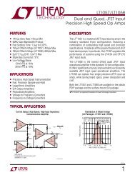
FUNCTIONAL BLOCK DIAGRAM<br />
REF V ANA<br />
4k<br />
2.5V<br />
CAP<br />
REFERENCE<br />
4R<br />
R1 IN<br />
2R<br />
R2 IN<br />
R 4R SWITCHED<br />
R3 IN CAP ADC<br />
R = 5k <strong>AD977</strong><br />
R = 2.5k <strong>AD977</strong>A<br />
CONTROL LOGIC &<br />
INTERNAL CALIBRATION CIRCUITRY<br />
PWRD<br />
R/C<br />
CS<br />
TAG<br />
AGND1<br />
<strong>AD977</strong>/<br />
<strong>AD977</strong>A<br />
SERIAL<br />
DATA<br />
INTERFACE<br />
CLOCK<br />
SB/BTC EXT/INT<br />
SYNC<br />
BUSY<br />
DATACLK<br />
DATA<br />
GENERAL DESCRIPTION<br />
The <strong>AD977</strong>/<strong>AD977</strong>A is a high speed, low power <strong>16</strong>-bit A/D<br />
converter that operates from a single 5 V supply. The <strong>AD977</strong>A<br />
has a throughput rate of <strong>200</strong> <strong>kSPS</strong> whereas the <strong>AD977</strong> has a<br />
throughput rate of <strong>100</strong> <strong>kSPS</strong>. Each part contains a successive<br />
approximation, switched capacitor ADC, an internal 2.5 V<br />
reference, and a high speed serial interface. The ADC is factory<br />
calibrated to minimize all linearity errors. The <strong>AD977</strong>/<strong>AD977</strong>A is<br />
specified for full scale bipolar input ranges of ± 10 V, ±5 V and<br />
± 3.3 V, and unipolar ranges of 0 V to 10 V, 0 V to 5 V and<br />
0 V to 4 V.<br />
The <strong>AD977</strong>/<strong>AD977</strong>A is comprehensively tested for ac parameters<br />
such as SNR and THD, as well as the more traditional dc<br />
parameters of offset, gain and linearity.<br />
PRODUCT HIGHLIGHTS<br />
1. Fast Throughput<br />
The <strong>AD977</strong>/<strong>AD977</strong>A is a high speed, <strong>16</strong>-bit ADC based on<br />
a factory calibrated switched capacitor architecture.<br />
2. Single-Supply Operation<br />
The <strong>AD977</strong>/<strong>AD977</strong>A operates from a single 5 V supply and<br />
dissipates only <strong>100</strong> mW max.<br />
3. Comprehensive DC and AC Specifications<br />
In addition to the traditional specifications of offset, gain<br />
and linearity, the <strong>AD977</strong>/<strong>AD977</strong>A is fully tested for SNR<br />
and THD.<br />
REV. D<br />
Information furnished by <strong>Analog</strong> <strong>Devices</strong> is believed to be accurate and<br />
reliable. However, no responsibility is assumed by <strong>Analog</strong> <strong>Devices</strong> for its<br />
use, nor for any infringements of patents or other rights of third parties<br />
which may result from its use. No license is granted by implication or<br />
otherwise under any patent or patent rights of <strong>Analog</strong> <strong>Devices</strong>.<br />
One Technology Way, P.O. Box 9106, Norwood, MA 02062-9106, U.S.A.<br />
Tel: 781/329-4700 World Wide Web Site: http://www.analog.com<br />
Fax: 781/326-8703 © <strong>Analog</strong> <strong>Devices</strong>, Inc., <strong>200</strong>0
<strong>AD977</strong>/<strong>AD977</strong>A<br />
<strong>AD977</strong>–SPECIFICATIONS (–40C to +85C, F S = <strong>100</strong> kHz, V DIG = V ANA = 5 V, unless otherwise noted)<br />
A Grade B Grade C Grade<br />
Parameter Min Typ Max Min Typ Max Min Typ Max Unit<br />
RESOLUTION <strong>16</strong> <strong>16</strong> <strong>16</strong> <strong>Bit</strong>s<br />
ANALOG INPUT<br />
Voltage Range ±10 V, 0 V to 5 V, . . . (See Table II)<br />
Impedance<br />
See Table II<br />
Sampling Capacitance 40 40 40 pF<br />
THROUGHPUT SPEED<br />
Complete Cycle 10 10 10 µs<br />
Throughput Rate <strong>100</strong> <strong>100</strong> <strong>100</strong> kHz<br />
DC ACCURACY<br />
Integral Linearity Error ±3 ±2.0 ±3 LSB 1<br />
Differential Linearity Error –2 +3 –1 +1.75 ±2 LSB<br />
No Missing Codes 15 <strong>16</strong> 15 <strong>Bit</strong>s<br />
Transition Noise 2 1.0 1.0 1.0 LSB<br />
Full-Scale Error 3, 4 ±0.5 ±0.25 ±0.5 %<br />
Full-Scale Error Drift ±7 ±7 ±7 ppm/°C<br />
Full-Scale Error<br />
Ext. REF = 2.5 V ±0.5 ±0.25 ±0.5 %<br />
Full-Scale Error Drift<br />
Ext. REF = 2.5 V ±2 ±2 ±2 ppm/°C<br />
Bipolar Zero Error 3<br />
Bipolar Ranges ±10 ±10 ±15 mV<br />
Bipolar Zero Error Drift<br />
Bipolar Ranges ±2 ±2 ±2 ppm/°C<br />
Unipolar Zero Error 3<br />
Unipolar Ranges ±10 ±10 ±10 mV<br />
Unipolar Zero Error Drift<br />
Unipolar Ranges ±2 ±2 ±2 ppm/°C<br />
Recovery to Rated Accuracy<br />
After Power-Down 5<br />
2.2 µF to CAP 1 1 1 ms<br />
Power Supply Sensitivity<br />
V ANA = V DIG = V D = 5 V ± 5% ±8 ±8 ±8 LSB<br />
AC ACCURACY<br />
Spurious Free Dynamic Range 6 90 96 90 dB 7<br />
Total Harmonic Distortion 6 –90 –96 –90 dB<br />
Signal-to-(Noise+Distortion) 6 83 85 83 dB<br />
–60 dB Input 27 28 27 dB<br />
Signal-to-Noise 6 83 85 83 dB<br />
Full Power Bandwidth 8 700 700 700 kHz<br />
–3 dB Input Bandwidth 1.5 1.5 1.5 MHz<br />
SAMPLING DYNAMICS<br />
Aperture Delay 40 40 40 ns<br />
Transient Response, Full-Scale Step 2 2 2 µs<br />
Overvoltage Recovery 9 150 150 150 ns<br />
REFERENCE<br />
Internal Reference Voltage 2.48 2.5 2.52 2.48 2.5 2.52 2.48 2.5 2.52 V<br />
Internal Reference Source Current 1 1 1 µA<br />
External Reference Voltage Range<br />
for Specified Linearity 2.3 2.5 2.7 2.3 2.5 2.7 2.3 2.5 2.7 V<br />
External Reference Current Drain<br />
Ext. REF = 2.5 V <strong>100</strong> <strong>100</strong> <strong>100</strong> µA<br />
NOTES<br />
1 LSB means Least Significant <strong>Bit</strong>. With a ± 10 V input, one LSB is 305 µV.<br />
2 Typical rms noise at worst case transitions and temperatures.<br />
3 Measured with fixed resistors as shown in Figures 11, 12 and 13. Adjustable to zero. Tested at room temperature.<br />
4 Full-Scale Error is expressed as the % difference between the actual full-scale code transition voltage and the ideal full scale transition voltage, and includes the effect of offset<br />
error. For bipolar input ranges, the Full-Scale Error is the worst case of either the –Full Scale or +Full Scale code transition voltage errors. For unipolar input ranges, Full-Scale<br />
Error is with respect to the +Full-Scale code transition voltage.<br />
5 External 2.5 V reference connected to REF.<br />
6 f IN = 20 kHz, 0.5 dB down unless otherwise noted.<br />
7 All specifications in dB are referred to a full scale ± 10 V input.<br />
8 Full-Power Bandwidth is defined as full-scale input frequency at which Signal-to-(Noise+Distortion) degrades to 60 dB, or 10 bits of accuracy.<br />
9 Recovers to specified performance after a 2 × F S input overvoltage.<br />
Specifications subject to change without notice.<br />
–2– REV. D
REV. D<br />
–3–<br />
<strong>AD977</strong>/<strong>AD977</strong>A<br />
<strong>AD977</strong>A–SPECIFICATIONS (–40C to +85C, F S = <strong>200</strong> kHz, V DIG = V ANA = 5 V, unless otherwise noted)<br />
A Grade B Grade C Grade<br />
Parameter Min Typ Max Min Typ Max Min Typ Max Unit<br />
RESOLUTION <strong>16</strong> <strong>16</strong> <strong>16</strong> <strong>Bit</strong>s<br />
ANALOG INPUT<br />
Voltage Range ±10 V, 0 V to 5 V, . . . (See Table II)<br />
Impedance<br />
See Table II<br />
Sampling Capacitance 40 40 40 pF<br />
THROUGHPUT SPEED<br />
Complete Cycle 5 5 5 µs<br />
Throughput Rate <strong>200</strong> <strong>200</strong> <strong>200</strong> kHz<br />
DC ACCURACY<br />
Integral Linearity Error ±3 ±2.0 ±3 LSB 1<br />
Differential Linearity Error –2 +3 –1 +1.75 ±2 LSB<br />
No Missing Codes 15 <strong>16</strong> 15 <strong>Bit</strong>s<br />
Transition Noise 2 1.0 1.0 1.0 LSB<br />
Full-Scale Error 3, 4 ±0.5 ±0.25 ±0.5 %<br />
Full-Scale Error Drift ±7 ±7 ±7 ppm/°C<br />
Full-Scale Error<br />
Ext. REF = 2.5 V ±0.5 ±0.25 ±0.5 %<br />
Full-Scale Error Drift<br />
Ext. REF = 2.5 V ±2 ±2 ±2 ppm/°C<br />
Bipolar Zero Error 3<br />
Bipolar Ranges ±10 ±10 ±15 mV<br />
Bipolar Zero Error Drift<br />
Bipolar Ranges ±2 ±2 ±2 ppm/°C<br />
Unipolar Zero Error 3<br />
Unipolar Ranges ±10 ±10 ±10 mV<br />
Unipolar Zero Error Drift<br />
Unipolar Ranges ±2 ±2 ±2 ppm/°C<br />
Recovery to Rated Accuracy<br />
After Power-Down 5<br />
2.2 µF to CAP 1 1 1 ms<br />
Power Supply Sensitivity<br />
V ANA = V DIG = V D = 5 V ± 5% ±8 ±8 ±8 LSB<br />
AC ACCURACY<br />
Spurious Free Dynamic Range 6 90 96 90 dB 7<br />
Total Harmonic Distortion 6 –90 –96 –90 dB<br />
Signal-to-(Noise+Distortion) 6 83 85 83 dB<br />
–60 dB Input 27 28 27 dB<br />
Signal-to-Noise 6 83 85 83 dB<br />
Full Power Bandwidth 8 1 1 1 MHz<br />
–3 dB Input Bandwidth 2.7 2.7 2.7 MHz<br />
SAMPLING DYNAMICS<br />
Aperture Delay 40 40 40 ns<br />
Transient Response, Full-Scale Step 1 1 1 µs<br />
Overvoltage Recovery 9 150 150 150 ns<br />
REFERENCE<br />
Internal Reference Voltage 2.48 2.5 2.52 2.48 2.5 2.52 2.48 2.5 2.52 V<br />
Internal Reference Source Current 1 1 1 µA<br />
External Reference Voltage Range<br />
for Specified Linearity 2.3 2.5 2.7 2.3 2.5 2.7 2.3 2.5 2.7 V<br />
External Reference Current Drain<br />
Ext. REF = 2.5 V 1.2 1.2 1.2 mA<br />
NOTES<br />
1 LSB means Least Significant <strong>Bit</strong>. With a ± 10 V input, one LSB is 305 µV.<br />
2 Typical rms noise at worst case transitions and temperatures.<br />
3 Measured with fixed resistors as shown in Figures 11, 12 and 13. Adjustable to zero. Tested at room temperature.<br />
4 Full-Scale Error is expressed as the % difference between the actual full-scale code transition voltage and the ideal full scale transition voltage, and includes the effect of offset<br />
error. For bipolar input ranges, the Full-Scale Error is the worst case of either the –Full Scale or +Full Scale code transition voltage errors. For unipolar input ranges, Full-Scale<br />
Error is with respect to the +Full-Scale code transition voltage.<br />
5 External 2.5 V reference connected to REF.<br />
6 f IN = 20 kHz, 0.5 dB down unless otherwise noted.<br />
7 All specifications in dB are referred to a full scale ± 10 V input.<br />
8 Full-Power Bandwidth is defined as full-scale input frequency at which Signal-to-(Noise+Distortion) degrades to 60 dB, or 10 bits of accuracy.<br />
9 Recovers to specified performance after a 2 × F S input overvoltage.<br />
Specifications subject to change without notice.
<strong>AD977</strong>/<strong>AD977</strong>A–SPECIFICATIONS (Both Specs)<br />
A, B, C Grades<br />
Parameter Conditions Min Typ Max Unit<br />
DIGITAL INPUTS<br />
Logic Levels<br />
V IL –0.3 +0.8 V<br />
V IH 2.0 V DIG + 0.3 V<br />
I IL ± 10 µA<br />
I IH ± 10 µA<br />
DIGITAL OUTPUTS<br />
Data Format<br />
Serial <strong>16</strong>-<strong>Bit</strong>s<br />
Data Coding Binary Two’s Complement or Straight Binary<br />
Pipeline Delay<br />
Conversion Results Only Available after Completed Conversion<br />
V OL I SINK = 1.6 mA 0.4 V<br />
V OH I SOURCE = 500 µA 4 V<br />
POWER SUPPLIES<br />
Specified Performance<br />
V DIG 4.75 5 5.25 V<br />
V ANA 4.75 5 5.25 V<br />
I DIG 4 mA<br />
I ANA 11 mA<br />
Power Dissipation<br />
PWRD LOW <strong>100</strong> mW<br />
PWRD HIGH 50 µW<br />
TEMPERATURE RANGE<br />
Specified Performance T MIN to T MAX –40 +85 °C<br />
Specifications subject to change without notice.<br />
TIMING SPECIFICATIONS<br />
<strong>AD977</strong>A<br />
<strong>AD977</strong><br />
Symbol Min Typ Max Min Typ Max Unit<br />
Convert Pulsewidth t 1 50 50 ns<br />
R/C, CS to BUSY Delay t 2 83 83 ns<br />
BUSY LOW Time t 3 4.0 8.0 µs<br />
BUSY Delay after End of Conversion t 4 50 50 ns<br />
Aperture Delay t 5 40 40 ns<br />
Conversion Time t 6 3.8 4.0 7.6 8.0 µs<br />
Acquisition Time t 7 1.0 2.0 µs<br />
Throughput Time t 6 + t 7 5 10 µs<br />
R/C Low to DATACLK Delay t 8 220 350 ns<br />
DATACLK Period t 9 220 450 ns<br />
DATA Valid Setup Time t 10 50 <strong>100</strong> ns<br />
DATA Valid Hold Time t 11 20 20 ns<br />
EXT. DATACLK Period t 12 66 <strong>100</strong> ns<br />
EXT. DATACLK HIGH t 13 20 20 ns<br />
EXT. DATACLK LOW t 14 30 30 ns<br />
R/C, CS to EXT. DATACLK Setup Time t 15 20 t 12 + 5 20 t 12 + 5 ns<br />
R/C to CS Setup Time t <strong>16</strong> 10 10 ns<br />
EXT. DATACLK to SYNC Delay t 17 15 66 15 66 ns<br />
EXT. DATACLK to DATA Valid Delay t 18 25 66 25 66 ns<br />
CS to EXT. DATACLK Rising Edge Delay t 19 10 10 ns<br />
Previous DATA Valid after CS, R/C Low t 20 3.5 7.5 µs<br />
BUSY to EXT. DATACLK Setup Time t 21 5 5 ns<br />
Final EXT. DATACLK to BUSY Rising Edge t 22 1.7 3.5 µs<br />
TAG Valid Setup Time t 23 0 0 ns<br />
TAG Valid Hold Time t 24 20 20 ns<br />
Specifications subject to change without notice.<br />
(<strong>AD977</strong>A: F S = <strong>200</strong> kHz, <strong>AD977</strong>: F S = <strong>100</strong> kHz, V DIG = V ANA = 5 V, –40C to +85C)<br />
–4– REV. D
<strong>AD977</strong>/<strong>AD977</strong>A<br />
ABSOLUTE MAXIMUM RATINGS 1<br />
<strong>Analog</strong> Inputs<br />
R1 IN , R2 IN , R3 IN . . . . . . . . . . . . . . . . . . . . . . . . . . . . ±25 V<br />
CAP . . . . . . . . . . . . . . . . .+V ANA + 0.3 V to AGND2 – 0.3 V<br />
REF . . . . . . . . . . . . . . . . . . . . . Indefinite Short to AGND2,<br />
. . . . . . . . . . . . . . . . . . . . . . . . . Momentary Short to V ANA<br />
Ground Voltage Differences<br />
DGND, AGND1, AGND2 . . . . . . . . . . . . . . . . . . . ±0.3 V<br />
Supply Voltages<br />
V ANA . . . . . . . . . . . . . . . . . . . . . . . . . . . . . . . . . . . . . . . 7 V<br />
V DIG to V ANA . . . . . . . . . . . . . . . . . . . . . . . . . . . . . . . . ±7 V<br />
V DIG . . . . . . . . . . . . . . . . . . . . . . . . . . . . . . . . . . . . . . . 7 V<br />
Digital Inputs . . . . . . . . . . . . . . . . . . . –0.3 V to V DIG + 0.3 V<br />
Internal Power Dissipation 2<br />
PDIP (N), SOIC (R), SSOP (RS) . . . . . . . . . . . . . 700 mW<br />
Junction Temperature . . . . . . . . . . . . . . . . . . . . . . . . . . 150°C<br />
Storage Temperature Range N, R . . . . . . . . –65°C to +150°C<br />
Lead Temperature Range<br />
(Soldering 10 sec) . . . . . . . . . . . . . . . . . . . . . . . . . . . 300°C<br />
NOTES<br />
1 Stresses above those listed under Absolute Maximum Ratings may cause permanent<br />
damage to the device. This is a stress rating only; functional operation of the<br />
device at these or any other conditions above those indicated in the operational<br />
section of this specification is not implied. Exposure to absolute maximum rating<br />
conditions for extended periods may affect device reliability.<br />
2 Specification is for device in free air:<br />
20-Lead PDIP: θ JA = <strong>100</strong>°C/W, θ JC = 31°C/W,<br />
20-Lead SOIC: θ JA = 75°C/W, θ JC = 24°C/W,<br />
28-Lead SSOP: θ JA = 109°C/W, θ JC = 39°C/W.<br />
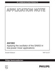
R1 IN 1<br />
AGND1 2<br />
R2 IN 3<br />
R3 IN 4<br />
CAP 5<br />
REF 6<br />
AGND2 7<br />
SB/BTC<br />
EXT/INT<br />
8<br />
9<br />
DGND 10<br />
SOIC and DIP<br />
<strong>AD977</strong><br />
<strong>AD977</strong>A<br />
TOP VIEW<br />
(Not to Scale)<br />
TO OUTPUT<br />
PIN<br />
PIN CONFIGURATIONS<br />
20 V DIG<br />
19 V ANA<br />
18 PWRD<br />
17 BUSY<br />
<strong>16</strong> CS<br />
15 R/C<br />
14 TAG<br />
13 DATA<br />
12 DATACLK<br />
11 SYNC<br />
C L<br />
<strong>100</strong>pF<br />
R1 IN 1<br />
AGND1 2<br />
R2 IN 3<br />
R3 IN 4<br />
NC 5<br />
CAP 6<br />
REF 7<br />
NC 8<br />
AGND2 9<br />
NC 10<br />
NC 11<br />
SB/BTC 12<br />
EXT/INT 13<br />
1.6mA<br />
DGND 14<br />
I OL<br />
SSOP<br />
<strong>AD977</strong><br />
<strong>AD977</strong>A<br />
TOP VIEW<br />
(Not to Scale)<br />
NC = NO CONNECT<br />
500A I OH<br />
1.4V<br />
28 V DIG<br />
27 V ANA<br />
26 PWRD<br />
25 BUSY<br />
24 CS<br />
23 NC<br />
22 NC<br />
21 R/C<br />
20 NC<br />
19 TAG<br />
18 NC<br />
17 DATA<br />
<strong>16</strong> DATACLK<br />
15 SYNC<br />
ORDERING GUIDE<br />
Figure 1. Load Circuit for Digital Interface Timing<br />
Temperature Throughput Package<br />
Model Range Rate Max INL Min S/(N+D) Options*<br />
<strong>AD977</strong>AN –40°C to +85°C <strong>100</strong> <strong>kSPS</strong> ± 3.0 LSB 83 dB N-20<br />
<strong>AD977</strong>BN –40°C to +85°C <strong>100</strong> <strong>kSPS</strong> ± 2.0 LSB 85 dB N-20<br />
<strong>AD977</strong>CN –40°C to +85°C <strong>100</strong> <strong>kSPS</strong> 83 dB N-20<br />
<strong>AD977</strong>AAN –40°C to +85°C <strong>200</strong> <strong>kSPS</strong> ± 3.0 LSB 83 dB N-20<br />
<strong>AD977</strong>ABN –40°C to +85°C <strong>200</strong> <strong>kSPS</strong> ± 2.0 LSB 85 dB N-20<br />
<strong>AD977</strong>ACN –40°C to +85°C <strong>200</strong> <strong>kSPS</strong> 83 dB N-20<br />
<strong>AD977</strong>AR –40°C to +85°C <strong>100</strong> <strong>kSPS</strong> ± 3.0 LSB 83 dB R-20<br />
<strong>AD977</strong>BR –40°C to +85°C <strong>100</strong> <strong>kSPS</strong> ± 2.0 LSB 85 dB R-20<br />
<strong>AD977</strong>CR –40°C to +85°C <strong>100</strong> <strong>kSPS</strong> 83 dB R-20<br />
<strong>AD977</strong>AAR –40°C to +85°C <strong>200</strong> <strong>kSPS</strong> ± 3.0 LSB 83 dB R-20<br />
<strong>AD977</strong>ABR –40°C to +85°C <strong>200</strong> <strong>kSPS</strong> ± 2.0 LSB 85 dB R-20<br />
<strong>AD977</strong>ACR –40°C to +85°C <strong>200</strong> <strong>kSPS</strong> 83 dB R-20<br />
<strong>AD977</strong>ARS –40°C to +85°C <strong>100</strong> <strong>kSPS</strong> ± 3.0 LSB 83 dB RS-28<br />
<strong>AD977</strong>BRS –40°C to +85°C <strong>100</strong> <strong>kSPS</strong> ± 2.0 LSB 85 dB RS-28<br />
<strong>AD977</strong>CRS –40°C to +85°C <strong>100</strong> <strong>kSPS</strong> 83 dB RS-28<br />
<strong>AD977</strong>AARS –40°C to +85°C <strong>200</strong> <strong>kSPS</strong> ± 3.0 LSB 83 dB RS-28<br />
<strong>AD977</strong>ABRS –40°C to +85°C <strong>200</strong> <strong>kSPS</strong> ± 2.0 LSB 85 dB RS-28<br />
<strong>AD977</strong>ACRS –40°C to +85°C <strong>200</strong> <strong>kSPS</strong> 83 dB RS-28<br />
*N = 20-lead 300 mil plastic DIP; R = 20-lead SOIC; RS = 28-lead SSOP.<br />
CAUTION<br />
ESD (electrostatic discharge) sensitive device. Electrostatic charges as high as 4000 V readily<br />
accumulate on the human body and test equipment and can discharge without detection.<br />
Although the <strong>AD977</strong>/<strong>AD977</strong>A feature proprietary ESD protection circuitry, permanent damage<br />
may occur on devices subjected to high-energy electrostatic discharges. Therefore, proper ESD<br />
precautions are recommended to avoid performance degradation or loss of functionality.<br />
WARNING!<br />
ESD SENSITIVE DEVICE<br />
REV. D<br />
–5–
<strong>AD977</strong>/<strong>AD977</strong>A<br />
PIN FUNCTION DESCRIPTIONS<br />
Pin No. Pin No.<br />
DIP/SOIC SSOP Mnemonic Description<br />
1, 3, 4 1, 3, 4 R1 IN , R2 IN , R3 IN <strong>Analog</strong> Input. Refer to Table I, Table II for input range configuration.<br />
2 2 AGND1 <strong>Analog</strong> Ground. Used as the ground reference point for the REF pin.<br />
5 6 CAP Reference buffer output. Connect a 2.2 µF tantalum capacitor between CAP and<br />
<strong>Analog</strong> Ground.<br />
6 7 REF Reference Input/Output. The internal 2.5 V reference is available at this pin.<br />
Alternatively an external reference can be used to override the internal reference. In<br />
either case, connect a 2.2 µF tantalum capacitor between REF and <strong>Analog</strong> Ground.<br />
7 9 AGND2 <strong>Analog</strong> Ground.<br />
8 12 SB/BTC This digital input is used to select the data format of a conversion result. With SB/BTC<br />
tied LOW, conversion data will be output in Binary Two’s Complement format. With<br />
SB/BTC connected to a logic HIGH, data is output in Straight Binary format.<br />
9 13 EXT/INT Digital select input for choosing the internal or an external data clock. With EXT/INT<br />
tied LOW, after initiating a conversion, <strong>16</strong> DATACLK pulses transmit the previous<br />
conversion result as shown in Figure 3. With EXT/INT set to a logic HIGH, output<br />
data is synchronized to an external clock signal connected to the DATACLK input.<br />
Data is output as indicated in Figure 4 through Figure 9.<br />
10 14 DGND Digital Ground.<br />
11 15 SYNC Digital output frame synchronization for use with an external data clock<br />
(EXT/INT = Logic HIGH). When a read sequence is initiated, a pulse one<br />
DATACLK period wide is output synchronous to the external data clock.<br />
12 <strong>16</strong> DATACLK Serial data clock input or output, dependent upon the logic state of the EXT/INT<br />
pin. When using the internal data clock (EXT/INT = Logic LOW), a conversion<br />
start sequence will initiate transmission of <strong>16</strong> DATACLK periods. Output data is<br />
synchronous to this clock and is valid on both its rising and falling edges (Figure 3).<br />
When using an external data clock (EXT/INT = Logic HIGH), the CS and R/C<br />
signals control how conversion data is accessed.<br />
13 17 DATA The serial data output is synchronized to DATACLK. Conversion results are<br />
stored in an on-chip register. The <strong>AD977</strong> provides the conversion result, MSB first,<br />
from its internal shift register. The DATA format is determined by the logic level of<br />
SB/BTC. When using the internal data clock (EXT/INT = Logic LOW), DATA is<br />
valid on both the rising and falling edges of DATACLK. Between conversions<br />
DATA will remain at the level of the TAG input when the conversion was started.<br />
Using an external data clock (EXT/INT = Logic HIGH) allows previous conversion<br />
data to be accessed during a conversion (Figures 5, 7 and 9) or the conversion<br />
result can be accessed after the completion of a conversion (Figures 4, 6 and 8).<br />
14 19 TAG This digital input can be used with an external data clock, (EXT/INT = Logic<br />
HIGH) to daisy chain the conversion results from two or more <strong>AD977</strong>s onto a<br />
single DATA line. The digital data level on TAG is output on DATA with a delay<br />
of <strong>16</strong> or 17 external DATACLK periods after the initiation of the read sequence.<br />
Dependent on whether a SYNC is not present or present.<br />
15 21 R/C Read/Convert Input. Is used to control the conversion and read modes of the<br />
<strong>AD977</strong>. With CS LOW; a falling edge on R/C holds the analog input signal internally<br />
and starts a conversion, a rising edge enables the transmission of the conversion<br />
result.<br />
<strong>16</strong> 24 CS Chip Select Input. With R/C LOW, a falling edge on CS will initiate a conversion.<br />
With R/C HIGH, a falling edge on CS will enable the serial data output sequence.<br />
17 25 BUSY Busy Output. Goes LOW when a conversion is started, and remains LOW until the<br />
conversion is completed and the data is latched into the on-chip shift register.<br />
18 26 PWRD Power-Down Input. When set to a logic HIGH power consumption is reduced and<br />
conversions are inhibited. The conversion result from the previous conversion is<br />
stored in the onboard shift register.<br />
19 27 V ANA <strong>Analog</strong> Power Supply. Nominally 5 V.<br />
20 28 V DIG Digital Power Supply. Nominally 5 V.<br />
–6– REV. D
<strong>AD977</strong>/<strong>AD977</strong>A<br />
DEFINITION OF SPECIFICATIONS<br />
INTEGRAL NONLINEARITY ERROR (INL)<br />
Linearity error refers to the deviation of each individual code<br />
from a line drawn from “negative full scale” through “positive<br />
full scale.” The point used as “negative full scale” occurs 1/2 LSB<br />
before the first code transition. “Positive full scale” is defined as<br />
a level 1 1/2 LSB beyond the last code transition. The deviation<br />
is measured from the middle of each particular code to the true<br />
straight line.<br />
DIFFERENTIAL NONLINEARITY ERROR (DNL)<br />
In an ideal ADC, code transitions are 1 LSB apart. Differential<br />
nonlinearity is the maximum deviation from this ideal value. It<br />
is often specified in terms of resolution for which no missing<br />
codes are guaranteed.<br />
FULL-SCALE ERROR<br />
The last + transition (from 011 . . . 10 to 011 . . . 11 for two’s<br />
complement format) should occur for an analog voltage 1 1/2 LSB<br />
below the nominal full scale (9.9995422 V for a ±10 V range).<br />
The full-scale error is the deviation of the actual level of the last<br />
transition from the ideal level.<br />
BIPOLAR ZERO ERROR<br />
Bipolar zero error is the difference between the ideal midscale<br />
input voltage (0 V) and the actual voltage producing the<br />
midscale output code.<br />
UNIPOLAR ZERO ERROR<br />
In unipolar mode, the first transition should occur at a level<br />
1/2 LSB above analog ground. Unipolar zero error is the deviation<br />
of the actual transition from that point.<br />
SPURIOUS FREE DYNAMIC RANGE<br />
The difference, in decibels (dB), between the rms amplitude of<br />
the input signal and the peak spurious signal.<br />
TOTAL HARMONIC DISTORTION (THD)<br />
THD is the ratio of the rms sum of the first six harmonic components<br />
to the rms value of a full-scale input signal and is<br />
expressed in decibels.<br />
SIGNAL TO (NOISE AND DISTORTION) (S/[N+D]) RATIO<br />
S/(N+D) is the ratio of the rms value of the measured input<br />
signal to the rms sum of all other spectral components below the<br />
Nyquist frequency, including harmonics but excluding dc. The<br />
value for S/(N+D) is expressed in decibels.<br />
FULL POWER BANDWIDTH<br />
The full power bandwidth is defined as the full-scale input frequency<br />
at which the S/(N+D) degrades to 60 dB, 10 bits of<br />
accuracy.<br />
APERTURE DELAY<br />
Aperture delay is a measure of the acquisition performance, and<br />
is measured from the falling edge of the R/C input to when the<br />
input signal is held for a conversion.<br />
TRANSIENT RESPONSE<br />
The time required for the <strong>AD977</strong>/<strong>AD977</strong>A to achieve its rated<br />
accuracy after a full-scale step function is applied to its input.<br />
OVERVOLTAGE RECOVERY<br />
The time required for the ADC to recover to full accuracy after<br />
an analog input signal 150% of full-scale is reduced to 50% of<br />
the full-scale value.<br />
REV. D<br />
–7–
<strong>AD977</strong>/<strong>AD977</strong>A<br />
CONVERSION CONTROL<br />
The <strong>AD977</strong>/<strong>AD977</strong>A is controlled by two signals: R/C and CS.<br />
When R/C is brought low, with CS low, for a minimum of 50 ns,<br />
the input signal will be held on the internal capacitor array and<br />
a conversion “n” will begin. Once the conversion process does<br />
begin, the BUSY signal will go low until the conversion is complete.<br />
Internally, the signals R/C and CS are OR’d together and<br />
there is no requirement on which signal is taken low first when<br />
initiating a conversion. The only requirement is that there be at<br />
least 10 ns of delay between the two signals being taken low.<br />
After the conversion is complete the BUSY signal will return<br />
high and the <strong>AD977</strong>/<strong>AD977</strong>A will again resume tracking the<br />
input signal. Under certain conditions the CS pin can be tied<br />
Low and R/C will be used to determine whether you are initiating<br />
a conversion or reading data. On the first conversion, after<br />
the <strong>AD977</strong>/<strong>AD977</strong>A is powered up, the DATA output will be<br />
indeterminate.<br />
Conversion results can be clocked serially out of the <strong>AD977</strong>/<br />
<strong>AD977</strong>A using either an internal clock, generated by the<br />
<strong>AD977</strong>/<strong>AD977</strong>A, or by using an external clock. The <strong>AD977</strong>/<br />
<strong>AD977</strong>A is configured for the internal data clock mode by pulling<br />
the EXT/INT pin low. It is configured for the external clock<br />
mode by pulling the EXT/INT pin high.<br />
INTERNAL DATA CLOCK MODE<br />
The <strong>AD977</strong>/<strong>AD977</strong>A is configured to generate and provide the<br />
data clock when the EXT/INT pin is held low. Typically CS will<br />
be tied low and R/C will be used to initiate a conversion “n.”<br />
During the conversion the <strong>AD977</strong>/<strong>AD977</strong>A will output <strong>16</strong> bits of<br />
data, MSB first, from conversion “n-1” on the DATA pin. This<br />
data will be synchronized with <strong>16</strong> clock pulses provided on the<br />
DATACLK pin. The output data will be valid on both the<br />
rising and falling edge of the data clock as shown in Figure 3.<br />
After the LSB has been presented, the DATA pin will assume<br />
whatever state the TAG input was at during the start of conversion,<br />
and the DATACLK pin will stay low until another<br />
conversion is initiated.<br />
EXTERNAL DATA CLOCK MODE<br />
The <strong>AD977</strong>/<strong>AD977</strong>A is configured to accept an externally supplied<br />
data clock when the EXT/INT pin is held high. This mode<br />
of operation provides several methods by which conversion<br />
results can be read from the <strong>AD977</strong>/<strong>AD977</strong>A. The output data<br />
from conversion “n-1” can be read during conversion “n,” or the<br />
output data from conversion “n” can be read after the conversion<br />
is complete. The external clock can be either a continuous<br />
or discontinuous clock. A discontinuous clock can be either<br />
t 1<br />
t 3<br />
CS, R/C<br />
BUSY<br />
t 2<br />
t 5<br />
t 6<br />
t 4<br />
t 7<br />
MODE ACQUIRE<br />
CONVERT<br />
ACQUIRE CONVERT<br />
Figure 2. Basic Conversion Timing<br />
t 8<br />
t 11<br />
t 6<br />
R/C<br />
t 1<br />
t 9<br />
DATACLK<br />
DATA<br />
1 2 3 15 <strong>16</strong><br />
t 10<br />
BIT 14 BIT 13<br />
BIT 1<br />
MSB VALID<br />
VALID VALID<br />
VALID<br />
LSB VALID<br />
t 2<br />
BUSY<br />
Figure 3. Serial Data Timing for Reading Previous Conversion Results with Internal Clock (CS, EXT/INT and TAG Set to<br />
Logic Low)<br />
–8– REV. D
<strong>AD977</strong>/<strong>AD977</strong>A<br />
normally low or normally high when inactive. In the case of the<br />
discontinuous clock, the <strong>AD977</strong>/<strong>AD977</strong>A can be configured to<br />
either generate or not generate a SYNC output (with a continuous<br />
clock a SYNC output will always be produced).<br />
Each of the methods will be described in the following sections<br />
and are illustrated in Figures 4 through 9. It should be noted<br />
that all timing diagrams assume that the receiving device is<br />
latching data on the rising edge of the external clock. If the<br />
falling edge of DATACLK is used then, in the case of a discontinuous<br />
clock, one less clock pulse is required than shown in<br />
Figures 4 through 7 to latch in a <strong>16</strong>-bit word. Note that data is<br />
valid on the falling edge of a clock pulse (for t 13 greater than t 18 )<br />
and the rising edge of the next clock pulse.<br />
The <strong>AD977</strong> provides error correction circuitry that can correct<br />
for an improper bit decision made during the first half of the<br />
conversion cycle. Normally the occurrence of an incorrect bit<br />
decision during a conversion cycle is irreversible. This error<br />
occurs as a result of noise during the time of the decision or due<br />
to insufficient settling time. As the <strong>AD977</strong>/<strong>AD977</strong>A is performing<br />
a conversion it is important that transitions not occur on<br />
digital input/output pins or degradation of the conversion result<br />
could occur. This is particularly important during the second<br />
half of the conversion process. For this reason it is recommended<br />
that when an external clock is being provided it be a discontinuous<br />
clock that is not toggling during the time that BUSY is low<br />
or, more importantly, that it does not transition during the latter<br />
half of BUSY low.<br />
EXTERNAL DISCONTINUOUS CLOCK DATA READ<br />
AFTER CONVERSION NO SYNC OUTPUT GENERATED<br />
Figure 4 illustrates the method by which data from conversion<br />
“n” can be read after the conversion is complete using a discontinuous<br />
external clock without the generation of a SYNC<br />
output. After a conversion is complete, indicated by BUSY<br />
returning high, the result of that conversion can be read while<br />
CS is Low and R/C is high. In this mode CS can be tied low.<br />
The MSB will be valid on the first falling edge and the second<br />
rising edge of DATACLK. The LSB will be valid on the <strong>16</strong>th<br />
falling edge and the 17th rising edge of DATACLK. A minimum<br />
of <strong>16</strong> clock pulses are required for DATACLK if the<br />
receiving device will be latching data on the falling edge of<br />
DATACLK. A minimum of 17 clock pulses are required for<br />
DATACLK if the receiving device will be latching data on the<br />
rising edge of DATACLK. Approximately 40 ns after the 17th<br />
rising edge of DATACLK (if provided) the DATA output pin<br />
will reflect the state of the TAG input pin during the first rising<br />
edge of DATACLK.<br />
The advantage of this method of reading data is that it is not<br />
being clocked out during a conversion and therefore conversion<br />
performance is not degraded.<br />
When reading data after the conversion is complete, with the<br />
highest frequency permitted for DATACLK (15.15 MHz), and<br />
with the <strong>AD977</strong>A, the maximum possible throughput is approximately<br />
195 kHz and not the rated <strong>200</strong> kHz.<br />
For details on use of the TAG input with this mode see the Use<br />
of the Tag Feature section.<br />
t 12<br />
t 13<br />
t 14<br />
EXT<br />
DATACLK<br />
0 1 2 3 14 15 <strong>16</strong><br />
t 1<br />
R/C<br />
BUSY<br />
SYNC<br />
DATA<br />
t 2<br />
t 24<br />
t 21<br />
BIT 13 BIT 1<br />
t 18<br />
BIT 15<br />
(MSB)<br />
BIT 14<br />
BIT 0<br />
(LSB)<br />
t 18<br />
TAG 18<br />
TAG 0 TAG 1<br />
t 23<br />
TAG<br />
TAG 0 TAG 1 TAG 2 TAG 3 TAG 15 TAG <strong>16</strong> TAG 17<br />
Figure 4. Conversion and Read Timing Using an External Discontinuous Data Clock (EXT/ INT Set to Logic High, CS Set<br />
to Logic Low)<br />
REV. D<br />
–9–
<strong>AD977</strong>/<strong>AD977</strong>A<br />
EXTERNAL DISCONTINUOUS CLOCK DATA READ<br />
DURING CONVERSION NO SYNC OUTPUT<br />
GENERATED<br />
Figure 5 illustrates the method by which data from conversion<br />
“n-1” can be read during conversion “n” while using a discontinuous<br />
external clock, without the generation of a SYNC output.<br />
After a conversion is initiated, indicated by BUSY going<br />
low, the result of the previous conversion can be read while CS<br />
is low and R/C is high. In this mode CS can be tied low. The<br />
MSB will be valid on the 1st falling edge and the 2nd rising<br />
edge of DATACLK. The LSB will be valid on the <strong>16</strong>th falling<br />
edge and the 17th rising edge of DATACLK. A minimum of <strong>16</strong><br />
clock pulses are required for DATACLK if the receiving device<br />
will be latching data on the falling edge of DATACLK. A minimum<br />
of 17 clock pulses are required for DATACLK if the<br />
receiving device will be latching data on the rising edge of<br />
DATACLK. Approximately 40 ns after the 17th rising edge of<br />
DATACLK (if provided) the DATA output pin will reflect the<br />
state of the TAG input pin during the first rising edge of<br />
DATACLK.<br />
For both the <strong>AD977</strong> and the <strong>AD977</strong>A the data should be<br />
clocked out during the first half of BUSY so not to degrade<br />
conversion performance. For the <strong>AD977</strong> this requires use of a<br />
4.8 MHz DATACLK or greater with data being read out as<br />
soon as the conversion process begins. For the <strong>AD977</strong>A it<br />
requires use of a 10 MHz DATACLK or greater.<br />
It is not recommended that data be shifted through the TAG<br />
input in this mode as it will certainly result in clocking of data<br />
during the second half of the conversion.<br />
EXTERNAL DISCONTINUOUS CLOCK DATA READ<br />
AFTER CONVERSION WITH SYNC OUTPUT GENERATED<br />
Figure 6 illustrates the method by which data from conversion<br />
“n” can be read after the conversion is complete using a discontinuous<br />
external clock, with the generation of a SYNC output.<br />
What permits the generation of a SYNC output is a transition of<br />
DATACLK while either CS is high or while both CS and R/C<br />
are low. After a conversion is complete, indicated by BUSY<br />
returning high, the result of that conversion can be read while<br />
CS is Low and R/C is high. In this mode CS can be tied low. In<br />
Figure 6 clock pulse #0 is used to enable the generation of a<br />
SYNC pulse. The SYNC pulse is actually clocked out approximately<br />
40 ns after the rising edge of clock pulse #1. The SYNC<br />
pulse will be valid on the falling edge of clock pulse #1 and the<br />
rising edge of clock pulse #2. The MSB will be valid on the<br />
falling edge of clock pulse #2 and the rising edge of clock pulse<br />
#3. The LSB will be valid on the falling edge of clock pulse #17<br />
and the rising edge of clock pulse #18. Approximately 40 ns<br />
after the rising edge of clock pulse #18 the DATA output pin<br />
will reflect the state of the TAG input pin during the rising edge<br />
of clock pulse #2. The advantage of this method of reading data<br />
is that it is not being clocked out during a conversion and therefore<br />
conversion performance is not degraded.<br />
When reading data after the conversion is complete, with the<br />
highest frequency permitted for DATACLK (15.15 MHz),<br />
and with the <strong>AD977</strong>A, the maximum possible throughput is<br />
approximately 195 kHz and not the rated <strong>200</strong> kHz.<br />
For details on use of the TAG input with this mode see the Use<br />
of the TAG Input section.<br />
t 12<br />
t 13 t 14<br />
EXT<br />
DATACLK<br />
0 1 2<br />
15 <strong>16</strong><br />
DATA<br />
R/C<br />
BUSY<br />
t 15<br />
t 1<br />
t 20<br />
t 2 t 21<br />
t 18<br />
BIT 15<br />
(MSB)<br />
BIT 14<br />
BIT 0<br />
(LSB)<br />
t 22<br />
SYNC<br />
t 18<br />
Figure 5. Conversion and Read Timing for Reading Previous Conversion Results During A Conversion Using External<br />
Discontinuous Data Clock (EXT/INT Set to Logic High, CS Set to Logic Low)<br />
–10– REV. D
<strong>AD977</strong>/<strong>AD977</strong>A<br />
t 12<br />
t 14<br />
t 13<br />
BIT 15<br />
EXT<br />
DATACLK<br />
0 1 2 3 4<br />
17 18<br />
t 15 t 15 t 15<br />
t 12<br />
t 18<br />
R/C<br />
BUSY<br />
SYNC<br />
DATA<br />
(MSB)<br />
t 2<br />
t 17<br />
BIT 0<br />
BIT 14<br />
(LSB)<br />
t 18<br />
TAG 19<br />
TAG 0 TAG 1<br />
TAG 2<br />
t 23<br />
t 24<br />
TAG<br />
TAG 0 TAG 1 TAG 2 TAG <strong>16</strong> TAG 17 TAG 18<br />
Figure 6. Conversion and Read Timing Using An External Discontinuous Data Clock (EXT/ INT Set to Logic High, CS Set<br />
to Logic Low)<br />
EXTERNAL DISCONTINUOUS CLOCK DATA READ<br />
DURING CONVERSION WITH SYNC OUTPUT<br />
GENERATED<br />
Figure 7 illustrates the method by which data from conversion<br />
“n-1” can be read during conversion “n” while using a discontinuous<br />
external clock, with the generation of a SYNC output.<br />
What permits the generation of a SYNC output is a transition of<br />
DATACLK while either CS is High or while both CS and R/C<br />
are low. In Figure 7 a conversion is initiated by taking R/C low<br />
with CS tied low. While this condition exists a transition of<br />
DATACLK, clock pulse #0, will enable the generation of a<br />
SYNC pulse. Less then 83 ns after R/C is taken low the BUSY<br />
output will go low to indicate that the conversion process has<br />
began. Figure 7 shows R/C then going high and after a delay of<br />
greater than 15 ns (t 15 ) clock pulse #1 can be taken high to<br />
request the SYNC output. The SYNC output will appear<br />
approximately 40 ns after this rising edge and will be valid on<br />
the falling edge of clock pulse #1 and the rising edge of clock<br />
pulse #2. The MSB will be valid approximately 40 ns after the<br />
rising edge of clock pulse #2 and can be latched off either the<br />
falling edge of clock pulse #2 or the rising edge of clock pulse<br />
#3. The LSB will be valid on the falling edge of clock pulse #17<br />
and the rising edge of clock pulse #18. Approximately 40 ns<br />
after the rising edge of clock pulse #18, the DATA output<br />
pin will reflect the state of the TAG input pin during the<br />
rising edge of clock pulse #2.<br />
t 12<br />
t 13<br />
t 14<br />
EXT<br />
DATACLK<br />
0 1 2 3 18<br />
DATA<br />
BIT 14<br />
R/C<br />
BUSY<br />
t 15<br />
BIT 15<br />
(MSB)<br />
t 15<br />
t 20<br />
(LSB)<br />
TAG 0<br />
t 22<br />
t 1<br />
t 12<br />
BIT 0<br />
t 2<br />
t 17<br />
t 18 t 18<br />
SYNC<br />
Figure 7. Conversion and Read Timing for Reading Previous Conversion Results During a Conversion Using External<br />
Discontinuous Data Clock (EXT/ INT Set to Logic High, CS Set to Logic Low)<br />
REV. D<br />
–11–
<strong>AD977</strong>/<strong>AD977</strong>A<br />
For both the <strong>AD977</strong> and the <strong>AD977</strong>A the data should be<br />
clocked out during the first half of BUSY so not to degrade<br />
conversion performance. For the <strong>AD977</strong> this requires use of a<br />
4.8 MHz DATACLK or greater, with data being read out as<br />
soon as the conversion process begins. For the <strong>AD977</strong>A it<br />
requires use of a 10 MHz DATACLK or greater.<br />
It is not recommended that data be shifted through the TAG<br />
input in this mode as it will certainly result in clocking of data<br />
during the second half of the conversion.<br />
EXTERNAL CONTINUOUS CLOCK DATA READ AFTER<br />
CONVERSION WITH SYNC OUTPUT GENERATED<br />
Figure 8 illustrates the method by which data from conversion<br />
“n” can be read after the conversion is complete using a continuous<br />
external clock, with the generation of a SYNC output.<br />
What permits the generation of a SYNC output is a transition of<br />
DATACLK while either CS is high or while both CS and R/C are<br />
low.<br />
With a continuous clock the CS pin cannot be tied low as it<br />
could be with a discontinuous clock. Use of a continuous clock,<br />
while a conversion is occurring, can increase the DNL and<br />
Transition Noise of the <strong>AD977</strong>/<strong>AD977</strong>A.<br />
After a conversion is complete, indicated by BUSY returning<br />
high, the result of that conversion can be read while CS is low<br />
and R/C is high. In Figure 8 clock pulse #0 is used to enable the<br />
generation of a SYNC pulse. The SYNC pulse is actually clocked<br />
out approximately 40 ns after the rising edge of clock pulse #1.<br />
The SYNC pulse will be valid on the falling edge of clock pulse<br />
#1 and the rising edge of clock pulse #2. The MSB will be valid<br />
on the falling edge of clock pulse #2 and the rising edge of clock<br />
pulse #3. The LSB will be valid on the falling edge of clock<br />
pulse #17 and the rising edge of clock pulse #18. Approximately<br />
50 ns after the rising edge of clock pulse #18 the DATA output<br />
pin will reflect the state of the TAG input pin during the rising<br />
edge of clock pulse #2.<br />
When reading data after the conversion is complete, with the<br />
highest frequency permitted for DATACLK (15.15 MHz) and,<br />
with the <strong>AD977</strong>A, the maximum possible throughput is approximately<br />
195 kHz and not the rated <strong>200</strong> kHz.<br />
For details on use of the TAG input with this mode see the Use<br />
of the TAG Input section.<br />
EXT<br />
DATACLK<br />
t 13<br />
0<br />
t 14<br />
t 12<br />
1 2 3 4 17 18<br />
CS<br />
R/C<br />
t <strong>16</strong><br />
t 1 t 15<br />
t <strong>16</strong><br />
t 17<br />
t 19<br />
t 2<br />
TAG 2<br />
BUSY<br />
SYNC<br />
t 12<br />
DATA<br />
t 18<br />
t 18<br />
BIT 15<br />
BIT 0<br />
(MSB) BIT 14<br />
(LSB)<br />
t 23<br />
t 24<br />
TAG 0 TAG 1 TAG 2<br />
TAG<br />
TAG 0 TAG 1<br />
TAG <strong>16</strong> TAG 17 TAG 18 TAG 19<br />
Figure 8. Conversion and Read Timing Using an External Continuous Data Clock (EXT/INT Set to Logic High)<br />
–12– REV. D
<strong>AD977</strong>/<strong>AD977</strong>A<br />
EXTERNAL CONTINUOUS CLOCK DATA READ DURING<br />
CONVERSION WITH SYNC OUTPUT GENERATED<br />
Figure 9 illustrates the method by which data from conversion<br />
“n-1” can be read during conversion “n” while using a continuous<br />
external clock with the generation of a SYNC output. What<br />
permits the generation of a SYNC output is a transition of<br />
DATACLK while either CS is high or while both CS and R/C<br />
are low.<br />
With a continuous clock the CS pin cannot be tied low as it<br />
could be with a discontinuous clock. Use of a continuous clock<br />
while a conversion is occurring can increase the DNL and<br />
Transition Noise of the <strong>AD977</strong>/<strong>AD977</strong>A.<br />
In Figure 9 a conversion is initiated by taking R/C low with CS<br />
held low. While this condition exists a transition of DATACLK,<br />
clock pulse #0, will enable the generation of a SYNC pulse.<br />
Less then 83 ns after R/C is taken low the BUSY output will go<br />
low to indicate that the conversion process has began. Figure 9<br />
shows R/C then going high and after a delay of greater than<br />
15 ns (t 15 ), clock pulse #1 can be taken high to request the<br />
SYNC output. The SYNC output will appear approximately<br />
50 ns after this rising edge and will be valid on the falling edge<br />
of clock pulse #1 and the rising edge of clock pulse #2. The<br />
MSB will be valid approximately 40 ns after the rising edge of<br />
clock pulse #2 and can be latched off either the falling edge of<br />
clock pulse #2 or the rising edge of clock pulse #3. The LSB<br />
will be valid on the falling edge of clock pulse #17 and the rising<br />
edge of clock pulse #18. Approximately 40 ns after the rising<br />
edge of clock pulse #18, the DATA output pin will reflect the<br />
state of the TAG input pin during the rising edge of clock<br />
pulse #2.<br />
For both the <strong>AD977</strong> and the <strong>AD977</strong>A the data should be<br />
clocked out during the 1st half of BUSY so as not to degrade<br />
conversion performance. For the <strong>AD977</strong> this requires use of a<br />
4.8 MHz DATACLK or greater with data being read out as<br />
soon as the conversion process begins. For the <strong>AD977</strong>A it<br />
requires use of a 10 MHz DATACLK or greater.<br />
t 13 t 14<br />
EXT<br />
DATACLK<br />
t 12<br />
0 1 2 3<br />
t 19<br />
18<br />
CS<br />
t 15<br />
R/C<br />
t <strong>16</strong><br />
t 1<br />
t 20<br />
BUSY<br />
t 2 t17<br />
t 12<br />
t 18<br />
SYNC<br />
DATA<br />
t 18<br />
BIT 15<br />
BIT 0<br />
(MSB)<br />
(LSB)<br />
TAG 0 TAG 1 TAG 2<br />
t 23 t 24<br />
TAG<br />
TAG 0<br />
TAG 1 TAG <strong>16</strong> TAG 17 TAG 18 TAG 19<br />
Figure 9. Conversion and Read Timing for Reading Previous Conversion Results During a Conversion Using An External<br />
Continuous Data Clock (EXT/ INT Set to Logic High)<br />
REV. D<br />
–13–
<strong>AD977</strong>/<strong>AD977</strong>A<br />
Table I. <strong>AD977</strong>A <strong>Analog</strong> Input Configuration<br />
Input Voltage Connect R1 IN Connect R2 IN Connect R3 IN Input<br />
Range via <strong>200</strong> to via <strong>100</strong> to to Impedance<br />
± 10 V V IN AGND 2.5 V 11.5 kΩ<br />
± 5 V AGND V IN 2.5 V 6.7 kΩ<br />
± 3.3 V V IN V IN 2.5 V 5.4 kΩ<br />
0 V to 10 V AGND V IN AGND 6.7 kΩ<br />
0 V to 5 V AGND AGND V IN 5.0 kΩ<br />
0 V to 4 V V IN AGND V IN 5.4 kΩ<br />
Table II. <strong>AD977</strong> <strong>Analog</strong> Input Configuration<br />
Input Voltage Connect R1 IN Connect R2 IN Connect R3 IN Input<br />
Range via <strong>200</strong> to via <strong>100</strong> to to Impedance<br />
± 10 V V IN AGND CAP 22.9 kΩ<br />
± 5 V AGND V IN CAP 13.3 kΩ<br />
± 3.3 V V IN V IN CAP 10.7 kΩ<br />
0 V to 10 V AGND V IN AGND 13.3 kΩ<br />
0 V to 5 V AGND AGND V IN 10.0 kΩ<br />
0 V to 4 V V IN AGND V IN 10.7 kΩ<br />
ANALOG INPUTS<br />
The <strong>AD977</strong>/<strong>AD977</strong>A is specified to operate with six full-scale<br />
analog input ranges. Connections required for each of the three<br />
analog inputs, R1 IN , R2 IN and R3 IN , and the resulting full-scale<br />
ranges, are shown in Table I and Table II. The nominal input<br />
impedance for each analog input range is also shown. Table III<br />
shows the output codes for the ideal input voltages of each of the<br />
six analog input ranges.<br />
The analog input section has a ± 25 V overvoltage protection on<br />
R1 IN and R2 IN . Since the <strong>AD977</strong>/<strong>AD977</strong>A has two analog<br />
grounds it is important to ensure that the analog input is referenced<br />
to the AGND1 pin, the low current ground. This will<br />
minimize any problems associated with a resistive ground drop.<br />
It is also important to ensure that the analog input of the<br />
<strong>AD977</strong>/<strong>AD977</strong>A is driven by a low impedance source. With its<br />
primarily resistive analog input circuitry, the ADC can be driven<br />
by a wide selection of general purpose amplifiers.<br />
To best match the low distortion requirements of the <strong>AD977</strong>/<br />
<strong>AD977</strong>A, care should be taken in the selection of the drive circuitry<br />
op amp.<br />
Figure 10 shows the simplified analog input section for the<br />
<strong>AD977</strong>/<strong>AD977</strong>A. Since the <strong>AD977</strong>/<strong>AD977</strong>A can operate with<br />
an internal or external reference, and several different analog<br />
input ranges, the full-scale analog input range is best represented<br />
with a voltage that spans 0 V to V REF across the 40 pF sampling<br />
capacitor. The onboard resistors are laser trimmed to ratio<br />
match for adjustment of offset and full-scale error using fixed<br />
external resistors.<br />
The configurations shown in Figures 12 and 13 are required to<br />
obtain the data sheet specifications for offset and full-scale error.<br />
The external fixed resistors are used during factory calibration so<br />
that a single 5 V supply can be used to bias the hardware trim<br />
circuitry. With the hardware adjust circuits shown in Figures 12<br />
and 13, offset and full-scale error can be trimmed to zero. Refer<br />
to the Offset and Gain Adjust section.<br />
If larger offset and full-scale errors are permitted, or if software<br />
calibration is used, the external resistors can be omitted.<br />
Table IV shows the resultant input ranges and offset and<br />
full-scale errors.<br />
Using the <strong>AD977</strong>A with Bipolar Input Ranges<br />
The connection diagrams in Figure 11 show a buffer amplifier<br />
required for bipolar operation of the <strong>AD977</strong>A when using the<br />
internal reference. The buffer amplifier is required to isolate the<br />
CAP pin from the signal dependent current in the R3 IN pin. A<br />
high speed op amp such as the AD8031 can be used with a<br />
single 5 V power supply without degrading the performance of<br />
the <strong>AD977</strong>A. The buffer must have good settling characteristics<br />
and provide low total noise within the input bandwidth of the<br />
<strong>AD977</strong>A.<br />
CAP<br />
R1 IN<br />
R2 IN<br />
R3 IN<br />
AGND2<br />
20k /10k<br />
10k /5k<br />
AGND1<br />
<strong>AD977</strong>/<strong>AD977</strong>A<br />
REF<br />
4k<br />
2.5V<br />
REFERENCE<br />
SWITCHED<br />
CAP ADC<br />
5k /2.5k 20k /10k 40pF<br />
Figure 10. <strong>AD977</strong>/<strong>AD977</strong>A Simplified <strong>Analog</strong> Input<br />
–14– REV. D
<strong>AD977</strong>/<strong>AD977</strong>A<br />
Table III. Output Codes and Ideal Input Voltages<br />
Digital Output<br />
Two’s Complement Straight Binary<br />
Description <strong>Analog</strong> Input (SB/BTC LOW) (SB/BTC HIGH)<br />
Full-Scale Range ±10 V ±5 V ±3.33 V 0 V to 10 V 0 V to 5 V 0 V to 4 V<br />
Least Significant <strong>Bit</strong> 305 µV 153 µV 102 µV 153 µV 76 µV 61 µV<br />
+Full Scale (FS–1 LSB) 9.999695 V 4.999847 V 3.333231 V 9.999847 V 4.999924 V 3.999939 V 0111 1111 1111 1111 1111 1111 1111 1111<br />
Midscale 0 V 0 V 0 V 5 V 2.5 V 2 V 0000 0000 0000 0000 <strong>100</strong>0 0000 0000 0000<br />
One LSB Below Midscale –305 µV –153 µV –102 µV 4.999847 V 2.499924 V 1.999939 V 1111 1111 1111 1111 0111 1111 1111 1111<br />
–Full Scale –10 V –5 V –3.333333 V 0 V 0 V 0 V <strong>100</strong>0 0000 0000 0000 0000 0000 0000 0000<br />
Table IV. Input Ranges, Offset and Full-Scale Errors Without External Resistors<br />
<strong>AD977</strong> Offset Error Full-Scale Error <strong>AD977</strong>A Offset Error Full-Scale Error<br />
Input Range A/B/C Grade A/B/C Grade Input Range A/B/C Grade A/B/C Grade<br />
–9.890 V to 9.90 V ±25 mV/±25 mV ±0.75%/±0.50% –9.800 V to 9.970 V ±40 mV/±40 mV ±0.80%/±0.55%<br />
–4.943 V to 4.995 V ±25 mV/±25 mV ±0.75%/±0.50% –4.900 V to 4.985 V ±40 mV/±40 mV ±0.80%/±0.55%<br />
–3.295 V to 3.330 V ±25 mV/±25 mV ±0.75%/±0.50% –3.267 V to 3.323 V ±40 mV/±40 mV ±0.80%/±0.55%<br />
0.008 V to 9.946 V ±10 mV/±10 mV ±0.75%/±0.50% 0.007 V to 9.893 V ±10 mV/±10 mV ±0.75%/±0.50%<br />
0.004 V to 5.023 V ±10 mV/±10 mV ±0.75%/±0.50% 0.004 V to 5.039 V ±10 mV/±10 mV ±0.75%/±0.50%<br />
0.003 V to 4.010 V ±10 mV/±10 mV ±0.75%/±0.50% 0.003 V to 4.0<strong>16</strong> V ±10 mV/±10 mV ±0.75%/±0.50%<br />
<strong>200</strong><br />
R1 IN<br />
<strong>200</strong><br />
R1 IN<br />
<strong>200</strong><br />
R1 IN<br />
V IN<br />
<strong>100</strong><br />
V IN<br />
<strong>100</strong><br />
AGND1<br />
AGND1<br />
AGND1<br />
R2 IN<br />
V IN<br />
<strong>100</strong><br />
R2 IN<br />
R2 IN<br />
33.2k<br />
2.2 F<br />
AD8031<br />
R3 IN<br />
CAP<br />
<strong>AD977</strong>A<br />
33.2k<br />
2.2 F<br />
AD8031<br />
R3 IN<br />
CAP<br />
<strong>AD977</strong>A<br />
33.2k<br />
AD8031<br />
2.2 F<br />
R3 IN<br />
CAP<br />
<strong>AD977</strong>A<br />
REF<br />
REF<br />
REF<br />
2.2 F<br />
AGND2<br />
2.2 F<br />
AGND2<br />
2.2 F<br />
AGND2<br />
a. b.<br />
c.<br />
Figure 11. <strong>AD977</strong>A Bipolar Input Configuration Using the Internal Reference; (a) V IN = ±10 V, (b) V IN = ±5 V, (c) V IN = ±3.33 V<br />
REV. D<br />
–15–
<strong>AD977</strong>/<strong>AD977</strong>A<br />
BIPOLAR CONNECTION FOR <strong>AD977</strong><br />
INPUT<br />
RANGE<br />
STANDARD CONNECTION WITHOUT<br />
OFFSET AND GAIN ADJUST<br />
STANDARD CONNECTION WITH<br />
OFFSET AND GAIN ADJUST<br />
V IN<br />
<strong>200</strong><br />
R1 IN<br />
V IN<br />
<strong>200</strong><br />
R1 IN<br />
AGND1<br />
AGND1<br />
10V<br />
<strong>100</strong><br />
33.2k<br />
2.2F<br />
2.2F<br />
R2 IN<br />
R3 IN<br />
CAP<br />
<strong>AD977</strong><br />
REF<br />
AGND2<br />
50k<br />
5V<br />
<strong>100</strong><br />
33.2k<br />
5V<br />
50k<br />
2.2F<br />
576k<br />
2.2F<br />
R2 IN<br />
R3 IN<br />
CAP<br />
<strong>AD977</strong><br />
REF<br />
AGND2<br />
5V<br />
V IN<br />
<strong>200</strong><br />
<strong>100</strong><br />
33.2k<br />
2.2F<br />
2.2F<br />
R1 IN<br />
AGND1<br />
R2 IN<br />
R3 IN<br />
CAP<br />
<strong>AD977</strong><br />
REF<br />
AGND2<br />
<strong>200</strong><br />
5V<br />
33.2k<br />
50k<br />
<strong>100</strong><br />
V IN<br />
5V 2.2F<br />
576k<br />
50k<br />
2.2F<br />
R1 IN<br />
AGND1<br />
R2 IN<br />
R3 IN<br />
CAP<br />
<strong>AD977</strong><br />
REF<br />
AGND2<br />
V IN<br />
<strong>200</strong><br />
R1 IN<br />
V IN<br />
<strong>200</strong><br />
R1 IN<br />
<strong>100</strong><br />
AGND1<br />
<strong>100</strong><br />
AGND1<br />
3.33V<br />
33.2k<br />
2.2F<br />
2.2F<br />
R2 IN<br />
R3 IN<br />
CAP<br />
<strong>AD977</strong><br />
REF<br />
AGND2<br />
50k<br />
5V<br />
33.2k<br />
5V<br />
50k<br />
2.2F<br />
576k<br />
2.2F<br />
R2 IN<br />
R3 IN<br />
CAP<br />
<strong>AD977</strong><br />
REF<br />
AGND2<br />
Figure 12. <strong>AD977</strong> Bipolar <strong>Analog</strong> Input Configuration<br />
–<strong>16</strong>– REV. D
<strong>AD977</strong>/<strong>AD977</strong>A<br />
UNIPOLAR CONNECTION FOR <strong>AD977</strong>A AND <strong>AD977</strong><br />
INPUT<br />
RANGE<br />
STANDARD CONNECTION WITHOUT<br />
OFFSET AND GAIN ADJUST<br />
STANDARD CONNECTION WITH<br />
OFFSET AND GAIN ADJUST<br />
<strong>200</strong><br />
R1 IN<br />
<strong>200</strong><br />
R1 IN<br />
AGND1<br />
AGND1<br />
0V–10V<br />
V IN<br />
<strong>100</strong><br />
33.2k<br />
2.2F<br />
2.2F<br />
R2 IN<br />
R3 IN<br />
CAP<br />
<strong>AD977</strong>/<br />
<strong>AD977</strong>A<br />
REF<br />
AGND2<br />
<strong>100</strong><br />
V IN<br />
5V<br />
2.2F<br />
33.2k<br />
50k<br />
5V<br />
576k<br />
50k<br />
2.2F<br />
R2 IN<br />
R3 IN<br />
CAP<br />
<strong>AD977</strong>/<br />
<strong>AD977</strong>A<br />
REF<br />
AGND2<br />
<strong>200</strong><br />
R1 IN<br />
<strong>200</strong><br />
R1 IN<br />
33.2k<br />
<strong>100</strong><br />
AGND1<br />
R2 IN<br />
50k<br />
5V<br />
33.2k<br />
<strong>100</strong><br />
AGND1<br />
R2 IN<br />
0V–5V<br />
V IN<br />
R3 IN<br />
V IN<br />
R3 IN<br />
2.2F<br />
2.2F<br />
CAP<br />
<strong>AD977</strong>/<br />
<strong>AD977</strong>A<br />
REF<br />
AGND2<br />
+<br />
2.2F<br />
–<br />
50k<br />
5V<br />
576k<br />
2.2F<br />
CAP<br />
<strong>AD977</strong>/<br />
<strong>AD977</strong>A<br />
REF<br />
AGND2<br />
V IN<br />
<strong>200</strong><br />
R1 IN<br />
V IN<br />
<strong>200</strong><br />
R1 IN<br />
<strong>100</strong><br />
AGND1<br />
R2 IN<br />
<strong>100</strong><br />
AGND1<br />
R2 IN<br />
0V–4V<br />
2.2F<br />
33.2k<br />
2.2F<br />
R3 IN<br />
CAP<br />
<strong>AD977</strong>/<br />
<strong>AD977</strong>A<br />
REF<br />
AGND2<br />
50k<br />
5V<br />
33.2k<br />
50k<br />
5V<br />
2.2F<br />
576k<br />
2.2F<br />
R3 IN<br />
CAP<br />
<strong>AD977</strong>/<br />
<strong>AD977</strong>A<br />
REF<br />
AGND2<br />
Figure 13. <strong>AD977</strong>/<strong>AD977</strong>A Unipolar <strong>Analog</strong> Input Configuration<br />
REV. D<br />
–17–
<strong>AD977</strong>/<strong>AD977</strong>A<br />
VOLTAGE REFERENCE<br />
The <strong>AD977</strong>/<strong>AD977</strong>A has an on-chip temperature compensated<br />
bandgap voltage reference that is factory trimmed to 2.5 V<br />
± 20 mV. The accuracy of the <strong>AD977</strong>/<strong>AD977</strong>A over the specified<br />
temperature ranges is dominated by the drift performance<br />
of the voltage reference. The on-chip voltage reference is lasertrimmed<br />
to provide a typical drift of 7 ppm/°C. This typical drift<br />
characteristic is shown in Figure 14, which is a plot of the<br />
change in reference voltage (in mV) versus the change in temperature—notice<br />
the plot is normalized for zero error at 25°C.<br />
If improved drift performance is required, an external reference<br />
such as the AD780 should be used to provide a drift as low as<br />
3 ppm/°C. In order to simplify the drive requirements of the<br />
voltage reference (internal or external), an onboard reference<br />
buffer is provided. The output of this buffer is provided at the<br />
CAP pin and is available to the user; however, when externally<br />
loading the reference buffer, it is important to make sure that<br />
proper precautions are taken to minimize any degradation in the<br />
ADC’s performance. Figure 15 shows the load regulation of the<br />
reference buffer. Notice that this figure is also normalized so<br />
that there is zero error with no dc load. In the linear region, the<br />
output impedance at this point is typically 1 Ω. Because of this<br />
1 Ω output impedance, it is important to minimize any ac or<br />
input dependent loads that will lead to increased distortion.<br />
Any dc loads will simply act as a gain error. Although the typical<br />
characteristic of Figure 15 shows that the <strong>AD977</strong>/<strong>AD977</strong>A<br />
is capable of driving loads greater than 15 mA, it is recommended<br />
that the steady state current not exceed 2 mA.<br />
Using an External Reference<br />
In addition to the on-chip reference, an external 2.5 V reference<br />
can be applied. When choosing an external reference for a<br />
<strong>16</strong>-bit application, however, careful attention should be paid to<br />
noise and temperature drift. These critical specifications can<br />
have a significant effect on the ADC performance.<br />
Figures <strong>16</strong>a and <strong>16</strong>b show the <strong>AD977</strong>/<strong>AD977</strong>A used in bipolar<br />
mode with the AD780 voltage reference applied to the REF<br />
pin. It is important to note that in Figure <strong>16</strong>a the R3 IN pin is<br />
connected to the CAP pin whereas in Figure <strong>16</strong>b the R3 IN pin<br />
of the <strong>AD977</strong>A is returned to the output of the external reference.<br />
The AD780 is a bandgap reference that exhibits ultralow<br />
drift, low initial error and low output noise. In Figure <strong>16</strong>b,<br />
the value for C1 is only applicable to applications using the<br />
AD780. In applications using a different external reference a<br />
different value for C1 may be required. For low power applications,<br />
the REF192 provides a low quiescent current, high<br />
accuracy and low temperature drift solution.<br />
V IN<br />
<strong>200</strong><br />
<strong>100</strong><br />
R1 IN<br />
R2 IN<br />
33.2k<br />
1mV/DIV<br />
5V<br />
0.1F<br />
3<br />
2<br />
TEMP<br />
V IN<br />
AD780<br />
V OUT<br />
6<br />
GND 4<br />
C3<br />
1F<br />
C1<br />
2.2F<br />
C4<br />
0.1F<br />
R3 IN<br />
REF<br />
AGND1<br />
<strong>AD977</strong><br />
V ANA<br />
–55<br />
25 125<br />
DEGREES CELSIUS<br />
C2<br />
2.2F<br />
CAP<br />
AGND2<br />
Figure 14. Reference Drift<br />
Figure <strong>16</strong>a. AD780 External Reference to <strong>AD977</strong> Configured<br />
for ±10 V Input Range<br />
dV ON CAP PIN – 10mV/DIV<br />
5V<br />
0.1F<br />
3<br />
2<br />
TEMP<br />
V IN<br />
V IN<br />
AD780<br />
V OUT<br />
6<br />
GND 4<br />
<strong>200</strong><br />
<strong>100</strong><br />
C3<br />
1F<br />
33.2k<br />
C1<br />
330F*<br />
C4<br />
0.1F<br />
R1 IN<br />
R2 IN<br />
R3 IN<br />
REF<br />
AGND1<br />
<strong>AD977</strong>A<br />
V ANA<br />
SOURCE CAPABILITY SINK CAPABILITY<br />
LOAD CURRENT – 5mA/DIV<br />
*ESR AT <strong>100</strong>kHz MUST BE LESS THAN 0.3.<br />
RECOMMEND KEMET T495 SERIES OR<br />
SANYO 6SA330M.<br />
C2<br />
2.2F<br />
CAP<br />
AGND2<br />
Figure 15. CAP Pin Load Regulation<br />
Figure <strong>16</strong>b. AD780 External Reference to <strong>AD977</strong>A Configured<br />
for ±10 V Input Range<br />
–18– REV. D
OFFSET AND GAIN ADJUSTMENT<br />
The <strong>AD977</strong>/<strong>AD977</strong>A is factory trimmed to minimize gain,<br />
offset and linearity errors. In some applications, where the analog<br />
input signal is required to meet the full dynamic range of the<br />
ADC, the gain and offset errors need to be externally trimmed<br />
to zero. Figures 12 and 13 show the required trim circuitry to<br />
correct for these offset and gain errors.<br />
Where adjustment is required, offset error must be corrected<br />
before gain error. To achieve this in the bipolar input configuration,<br />
trim the offset potentiometer with the input voltage set to<br />
1/2 LSB below ground. Then adjust the potentiometer until the<br />
major carry transition is located between 1111 1111 1111 1111<br />
and 0000 0000 0000 0000. To adjust the gain error, an analog<br />
signal should be input at either the first code transition (ADC<br />
negative full scale) or the last code transition (ADC positive full<br />
scale). Thus, to adjust for full-scale error, an input voltage of<br />
FS/2 – 3/2 LSBs can be applied to V IN , and the gain potentiometer<br />
should be adjusted until the output code flickers between<br />
the last positive code transition 0111 1111 1111 1111 and 0111<br />
1111 1111 1110. Should the first code transition need adjusting,<br />
the trim procedure should consist of applying an analog<br />
input signal of –FS/2 + 1/2 LSB to the V IN input and adjusting<br />
the trim until the output code flickers between <strong>100</strong>0 0000<br />
0000 0000 and <strong>100</strong>0 0000 0000 0001.<br />
AC PERFORMANCE<br />
The <strong>AD977</strong>/<strong>AD977</strong>A is fully specified and tested for dynamic<br />
performance specifications. The ac parameters are required for<br />
signal processing applications such as speech recognition and<br />
spectrum analysis. These applications require information on<br />
the ADC’s effect on the spectral content of the input signal.<br />
Hence, the parameters for which the <strong>AD977</strong>/<strong>AD977</strong>A is specified<br />
include S/(N+D), THD and Spurious Free Dynamic Range.<br />
These terms are discussed in greater detail in the following<br />
sections.<br />
As a general rule, it is recommended that the results from several<br />
conversions be averaged to reduce the effects of noise and<br />
thus improve parameters such as S/(N+D) and THD. The ac<br />
performance of the <strong>AD977</strong>/<strong>AD977</strong>A can be optimized by operating<br />
the ADC at its maximum sampling rate of <strong>100</strong> kHz/<strong>200</strong> kHz<br />
and digitally filtering the resulting bit stream to the desired signal<br />
bandwidth. By distributing noise over a wider frequency range<br />
the noise density in the frequency band of interest can be<br />
reduced. For example, if the required input bandwidth is 50 kHz,<br />
REV. D<br />
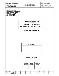
AMPLITUDE – dB<br />
0<br />
–10<br />
5280 POINT FFT<br />
–20<br />
F SAMPLE = <strong>200</strong>kHz<br />
F<br />
–30<br />
IN = 20kHz, 0dB<br />
SNRD = 86dB<br />
–40<br />
THD = –101dB<br />
–50<br />
–60<br />
–70<br />
–80<br />
–90<br />
–<strong>100</strong><br />
–110<br />
–120<br />
–130<br />
0 5 10 15 20 25 30 35 40 45 50 55 60 65 70 75 80 85 90 95 <strong>100</strong><br />
FREQUENCY – kHz<br />
Figure 17. FFT Plot<br />
–19–<br />
<strong>AD977</strong>/<strong>AD977</strong>A<br />
the <strong>AD977</strong>/<strong>AD977</strong>A could be oversampled by a factor of 2/4.<br />
This would yield a 3/6 dB improvement in the effective SNR<br />
performance.<br />
DC PERFORMANCE<br />
The factory calibration scheme used for the <strong>AD977</strong>/<strong>AD977</strong>A<br />
compensates for bit weight errors that may exist in the capacitor<br />
array. The mismatch in capacitor values is adjusted (using the<br />
calibration coefficients) during a conversion resulting in excellent<br />
dc linearity performance. Figures 18, 19, 20, 21, 22 and 23,<br />
respectively, show typical INL, typical DNL, typical positive and<br />
negative INL and DNL distribution plots for the <strong>AD977</strong>/<strong>AD977</strong>A<br />
at 25°C.<br />
A histogram test is a statistical method for deriving an A/D<br />
converter’s differential nonlinearity. A ramp input is sampled by<br />
the ADC and a large number of conversions are taken at each<br />
voltage level, averaged then stored. The effect of averaging is to<br />
reduce the transition noise by 1/n. If 64 samples are averaged at<br />
each point, the effect of transition noise is reduced by a factor of<br />
8, i.e., a transition noise of 0.8 LSBs rms is reduced to<br />
0.1 LSBs rms. Theoretically the codes, during a test of DNL,<br />
would all be the same size and therefore have an equal number<br />
of occurrences. A code with an average number of occurrences<br />
would have a DNL of “0.” A code that is different from the<br />
average would have a DNL that was either greater or less than<br />
zero LSB. A DNL of –1 LSB indicates that there is a missing<br />
code present at the <strong>16</strong>-bit level and that the ADC exhibits 15-<br />
bit performance.<br />
LSB<br />
LSB<br />
2.0<br />
1.5<br />
1.0<br />
0.5<br />
0<br />
–0.5<br />
–1.0<br />
–1.5<br />
<strong>100</strong>%<br />
–2.0<br />
0 5 10 15 20 25 30 35 40 45 50 55 60 66<br />
OUTPUT CODE – K<br />
2.0<br />
1.5<br />
1.0<br />
0.5<br />
0<br />
–0.5<br />
–1.0<br />
–1.5<br />
Figure 18. INL Plot<br />
<strong>100</strong>%<br />
–2.0<br />
0 5 10 15 20 25 30 35 40 45 50 55 60 66<br />
OUTPUT CODE – K<br />
Figure 19. DNL Plot
<strong>AD977</strong>/<strong>AD977</strong>A<br />
NUMBER OF UNITS<br />
50<br />
45<br />
40<br />
35<br />
30<br />
25<br />
20<br />
15<br />
10<br />
5<br />
0<br />
0<br />
0.2<br />
0.3<br />
0.4<br />
0.5<br />
0.6<br />
0.8<br />
0.9<br />
1<br />
1.1<br />
1.2<br />
1.4<br />
1.5<br />
1.6<br />
1.7<br />
1.8<br />
2<br />
POSITIVE INL – LSB<br />
2.1<br />
2.2<br />
2.3<br />
2.4<br />
2.6<br />
2.7<br />
2.8<br />
2.9<br />
Figure 20. Typical Positive INL Distribution (999 Units)<br />
NUMBER OF UNITS<br />
90<br />
80<br />
70<br />
60<br />
50<br />
40<br />
30<br />
20<br />
10<br />
0<br />
–1.22<br />
–1.17<br />
–1.12<br />
–1.07<br />
–1.02<br />
–0.97<br />
–0.92<br />
–0.87<br />
–0.82<br />
–0.78<br />
–0.73<br />
–0.68<br />
–0.63<br />
–0.58<br />
–0.53<br />
–0.48<br />
–0.43<br />
–0.38<br />
–0.33<br />
–0.28<br />
–0.23<br />
–0.18<br />
–0.14<br />
–0.09<br />
–0.04<br />
NEGATIVE DNL – LSB<br />
Figure 23. Typical Negative DNL Distribution (999 Units)<br />
NUMBER OF UNITS<br />
60<br />
50<br />
40<br />
30<br />
20<br />
10<br />
SINAD (dB) FOR V IN = 0dB<br />
90<br />
80<br />
70<br />
60<br />
50<br />
40<br />
30<br />
20<br />
SNR+D (dB) FOR <strong>AD977</strong>A<br />
SNR+D (dB) FOR <strong>AD977</strong><br />
0<br />
–2.5<br />
–2.4<br />
–2.3<br />
–2.2<br />
–2.1<br />
–2.0<br />
–1.9<br />
–1.8<br />
–1.7<br />
–1.6<br />
–1.5<br />
–1.4<br />
–1.3<br />
–1.2<br />
–1.1<br />
–1.0<br />
–0.9<br />
–0.8<br />
–0.7<br />
–0.6<br />
–0.5<br />
–0.4<br />
–0.3<br />
–0.2<br />
NEGATIVE INL – LSB<br />
Figure 21. Typical Negative INL Distribution (999 Units)<br />
–0.1<br />
10<br />
1 10 <strong>100</strong> <strong>100</strong>0<br />
INPUT SIGNAL FREQUENCY – kHz<br />
Figure 24. S/(N+D) vs. Input Frequency<br />
120<br />
110<br />
–80<br />
<strong>100</strong><br />
105<br />
SFDR<br />
–85<br />
NUMBER OF UNITS<br />
80<br />
60<br />
40<br />
SFDR, S/N+D – dB<br />
<strong>100</strong><br />
95<br />
90<br />
THD<br />
–90<br />
–95<br />
–<strong>100</strong><br />
THD – dB<br />
20<br />
85<br />
SNRD<br />
–105<br />
0<br />
0.02<br />
0.10<br />
0.19<br />
0.27<br />
0.36<br />
0.44<br />
0.52<br />
0.61<br />
0.69<br />
0.77<br />
0.86<br />
0.94<br />
1.02<br />
1.11<br />
1.19<br />
1.27<br />
1.36<br />
1.44<br />
1.53<br />
1.61<br />
1.69<br />
1.78<br />
1.86<br />
1.94<br />
2.03<br />
POSITIVE DNL – LSB<br />
Figure 22. Typical Positive DNL Distribution (999 Units)<br />
80<br />
–110<br />
–75 –50 –25 0 25 50 75 <strong>100</strong> 125 150<br />
TEMPERATURE – C<br />
Figure 25. AC Parameters vs. Temperature<br />
–20– REV. D
<strong>AD977</strong>/<strong>AD977</strong>A<br />
DC CODE UNCERTAINTY<br />
Ideally, a fixed dc input should result in the same output code<br />
for repetitive conversions; however, as a consequence of unavoidable<br />
circuit noise within the wideband circuits of the ADC, a<br />
range of output codes may occur for a given input voltage.<br />
Thus, when a dc signal is applied to the <strong>AD977</strong>/<strong>AD977</strong>A input<br />
and 10,000 conversions are recorded, the result will be a distribution<br />
of codes as shown in Figure 26. This histogram shows a<br />
bell shaped curve consistent with the Gaussian nature of thermal<br />
noise. The histogram is approximately seven codes wide. The<br />
standard deviation of this Gaussian distribution results in a code<br />
transition noise of 1 LSB rms.<br />
4000<br />
to throw away the null bit if the sync input is toggled each time<br />
the null bit appears.<br />
If the application does not require simultaneous sampling, the<br />
null bit can be completely avoided by delaying the R/C signal<br />
of each upstream device by one clock cycle with respect to its<br />
immediate downstream device. This bit time delay can be accomplished<br />
through a D-type flip-flop that delays the R/C signal at<br />
its D-input by one cycle of the serial data clock that is at its<br />
clock input.<br />
<strong>AD977</strong>/<strong>AD977</strong>A<br />
#2<br />
(UPSTREAM)<br />
TAG<br />
DATA<br />
<strong>AD977</strong>/<strong>AD977</strong>A<br />
#1<br />
(DOWNSTREAM)<br />
TAG<br />
DATA<br />
DATA OUT<br />
3500<br />
3000<br />
CS<br />
R/C<br />
DCLK<br />
CS<br />
R/C<br />
DCLK<br />
2500<br />
<strong>200</strong>0<br />
1500<br />
<strong>100</strong>0<br />
500<br />
0<br />
–3<br />
–2 –1 0 1 2 3 4<br />
Figure 26. Histogram of 10,000 Conversions of a DC Input<br />
USE OF THE TAG INPUT<br />
The <strong>AD977</strong>/<strong>AD977</strong>A provides a TAG input pin for cascading<br />
multiple converters together. This feature is useful for reducing<br />
component count in systems where an isolation barrier must be<br />
crossed and is also useful for systems with a limited capacity for<br />
interfacing to a large number of converters.<br />
The tag feature only works in the external clock mode and<br />
requires that the DATA output of a “upstream” device be connected<br />
to the TAG input of an “downstream” device.<br />
An example of the concatenation of two devices is shown in<br />
Figure 27 and their resultant output is shown in Figure 28.<br />
In Figure 27, the paralleled R/C ensures that each <strong>AD977</strong>/<br />
<strong>AD977</strong>A will simultaneously sample their inputs. In Figure 28,<br />
a “null” bit is shown between each <strong>16</strong>-bit word associated with<br />
each ADC in the serial data output stream. This is the result of<br />
a minimum value for “External Data Clock to Data Valid Delay”<br />
(t 18 ) that is greater than the “TAG Valid Setup Time” (t 23 ). In<br />
other words, when you concatenate two or more <strong>AD977</strong>/<strong>AD977</strong>As<br />
the MSB on the downstream device will not be present on the<br />
TAG input of the upstream device in time to meet the setup<br />
time requirement of the TAG input.<br />
If the serial data stream is going to a parallel port of a microprocessor<br />
that is also providing the serial data clock, then the<br />
microprocessor’s firmware can be written to “throw away” the<br />
null bit. If the serial data stream is going to a serial port then<br />
external “glue” logic will have to be added to make the interface<br />
work. If the serial port has a “sync” input then this can be used<br />
DCLK IN<br />
R/ IN<br />
IN<br />
Figure 27. Two <strong>AD977</strong>/<strong>AD977</strong>A’s Utilizing Tag<br />
It is not recommended that the TAG feature be used with the<br />
read during convert mode because this will require data to be<br />
clocked out during the second half of the conversion process. It<br />
is recommended that the read after convert mode be used in an<br />
application that wants to take advantage of the TAG feature. To<br />
improve the data throughput a combination of the two data read<br />
methods can be used and is described as follows.<br />
If two or more <strong>AD977</strong>/<strong>AD977</strong>As are to have their data output<br />
concatenated together in a single data stream, and if data<br />
throughput is to be maximized, a system could be designed such<br />
that the upstream device data is read during the first half of its<br />
conversion process and the remainder of the downstream devices<br />
read during the time between conversions. Assume three <strong>AD977</strong>As<br />
are to have their data concatenated. Assume the further most<br />
downstream device is referred to as device #1 and the further<br />
most upstream device as #3. Each device is driven from a common<br />
DATACLK and R/C control signal, the CS input of each<br />
device is tied to ground. The three BUSY outputs should be<br />
OR’d together to form a composite BUSY. After the conversion<br />
is complete, as indicated by the composite BUSY going high, an<br />
external, normally low, 15.15 MHz DATACLK can be toggled<br />
34 times to first read the data first from device #3 and then<br />
from device #2. When the composite BUSY goes low to indicate<br />
the beginning of the conversion process the external DATA-<br />
CLK can be toggled 17 times to read the data from device #1<br />
during the first half of the conversion process. Using this technique<br />
it would be possible to read in the data from the three<br />
devices in approximately 6.4 µs for a throughput of approximately<br />
156 kHz The receiving device would have to deal with<br />
the null bit between data from device #2 and #3. The receiving<br />
device would also have to be capable of starting and stopping<br />
the external DATACLK at the appropriate times.<br />
The TAG input, when unused, should always be tied either high<br />
or low and not be allowed to float.<br />
REV. D<br />
–21–
<strong>AD977</strong>/<strong>AD977</strong>A<br />
R/C<br />
BUSY<br />
DATA<br />
DCLK<br />
DEVICE DATA #1<br />
NULL BIT<br />
15 0 15<br />
DEVICE<br />
DATA #2<br />
Figure 28. TAG Timing Diagram for Two Concatenated<br />
<strong>AD977</strong>/<strong>AD977</strong>As<br />
POWER-DOWN FEATURE<br />
The <strong>AD977</strong>/<strong>AD977</strong>A has analog and reference power-down<br />
capability through the PWRD pin. When the PWRD pin is<br />
taken high, the power consumption drops from a maximum<br />
value of <strong>100</strong> mW to a typical value of 50 µW. When in the<br />
power-down mode the previous conversion results are still available<br />
in the internal registers and can be read out providing it has<br />
not already been shifted out.<br />
When used with an external reference, connected to the REF<br />
pin and a 2.2 µF capacitor, connected to the CAP pin, the<br />
power up recovery time is typically 1 ms. This typical value of<br />
1 ms for recovery time depends on how much charge has decayed<br />
from the external 2.2 µF capacitor on the CAP pin and assumes<br />
that it has decayed to zero. The 1 ms recovery time has been<br />
specified such that settling to <strong>16</strong>-bits has been achieved.<br />
When used with the internal reference, the dominant time constant<br />
for power-up recovery is determined by the external<br />
capacitor on the REF pin and the internal 4K impedance seen<br />
at that pin. An external 2.2 µF capacitor is recommended for the<br />
REF pin.<br />
CONSIDERATIONS WHEN USING MULTIPLEXED<br />
INPUTS<br />
Consideration must be given to the effect on A/D performance<br />
in applications that require the use of analog multiplexers or analog<br />
switches to interface multiple signals to the <strong>AD977</strong>/<strong>AD977</strong>A. The<br />
nonzero “on” resistance of a multiplexer or switch, at the input<br />
to the <strong>AD977</strong>/<strong>AD977</strong>A, will increase the system offset and gain<br />
error. As an example, consider the <strong>AD977</strong> configured for an input<br />
voltage range of ± 10 V dc. For every 5 Ω of source impedance<br />
(in addition to the required external <strong>200</strong> Ω input resistor) an<br />
offset error of 1 LSB would be introduced and the positive<br />
gain error would increase by an added 0.00375% of full scale.<br />
This error, due to nonzero source impedance, can be corrected<br />
through a hardware or software system level calibration,<br />
but will only be valid at the temperature and input voltage<br />
present at the time of calibration. Another factor to consider is<br />
that most analog multiplexers and switches exhibit a nonlinear<br />
relationship between input signal level and on resistance. This<br />
will introduce added distortion products that will degrade THD,<br />
S/(N+D) and INL. For these reasons it is recommended that an<br />
appropriate buffer be used between the output of the multiplexer<br />
and the input of the <strong>AD977</strong>.<br />
When switching the input to the multiplexer, and subsequently<br />
the input to the <strong>AD977</strong>, it is recommended that the transition<br />
be made to occur either immediately after the current conversion<br />
is complete or shortly after the beginning of a conversion.<br />
MICROPROCESSOR INTERFACING<br />
The <strong>AD977</strong>/<strong>AD977</strong>A is ideally suited for traditional dc measurement<br />
applications supporting a microprocessor, and ac<br />
signal processing applications interfacing to a digital signal<br />
processor. The <strong>AD977</strong>/<strong>AD977</strong>A is designed to interface with a<br />
general purpose serial port or I/O ports on a microcontroller. A<br />
variety of external buffers can be used with the <strong>AD977</strong>/<strong>AD977</strong>A<br />
to prevent digital noise from coupling into the ADC. The<br />
following sections illustrate the use of the <strong>AD977</strong>/<strong>AD977</strong>A with<br />
an SPI equipped microcontroller and the ADSP-2181 signal<br />
processor.<br />
SPI Interface<br />
Figure 29 shows a general interface diagram between the<br />
<strong>AD977</strong>/<strong>AD977</strong>A and an SPI equipped microcontroller. This<br />
interface assumes that the convert pulses will originate from the<br />
microcontroller and that the <strong>AD977</strong>/<strong>AD977</strong>A will act as the<br />
slave device. The convert pulse could be initiated in response to<br />
an internal timer interrupt. The reading of output data, one byte<br />
at a time, if necessary, could be initiated in response to the endof-conversion<br />
signal (BUSY going high).<br />
SDI<br />
SCK<br />
I/O PORT<br />
IRQ<br />
SPI<br />
+5V<br />
DATA<br />
DATACLK<br />
R/C<br />
BUSY<br />
EXT/INT<br />
CS<br />
TAG<br />
<strong>AD977</strong>/<br />
<strong>AD977</strong>A<br />
Figure 29. <strong>AD977</strong>/<strong>AD977</strong>A to SPI Interface<br />
ADSP-2181 Interface<br />
Figure 30 shows an interface between the <strong>AD977</strong>/<strong>AD977</strong>A and<br />
the ADSP-2181 Digital Signal Processor. The <strong>AD977</strong>/<strong>AD977</strong>A<br />
is configured for the Internal Clock mode (EXT/INT = 0) and<br />
will therefore act as the master device. The convert command is<br />
shown generated from an external oscillator in order to provide<br />
a low jitter signal appropriate for both dc and ac measurements.<br />
Because the SPORT, within the ADSP-2181, will be seeing a<br />
discontinuous external clock, some steps are required to ensure<br />
that the serial port is properly synchronized to this clock during<br />
each data read operation. The recommended procedure to ensure<br />
this is as follows,<br />
– enable SPORT0 through the System Control register<br />
– set the SCLK Divide register to zero<br />
– setup PF0 and PF1 as outputs by setting bits 0 and 1 in<br />
PFTYPE<br />
– force RFS0 low through PF0. The Receive Frame Sync signal<br />
has been programmed active high<br />
– enable <strong>AD977</strong>/<strong>AD977</strong>A by forcing CS = 0 through PF1<br />
– enable SPORT0 Receive Interrupt through the IMASK register<br />
– wait for at least one full conversion cycle of the <strong>AD977</strong>/<strong>AD977</strong>A<br />
and throw away the received data<br />
– disable the <strong>AD977</strong>/<strong>AD977</strong>A by forcing CS = 1 through PF1<br />
– wait for a period of time equal to one conversion cycle<br />
– force RFS0 high through PF0<br />
– enable the <strong>AD977</strong>/<strong>AD977</strong>A by forcing CS = 0 through PF1<br />
–22– REV. D
<strong>AD977</strong>/<strong>AD977</strong>A<br />
The ADSP-2181 SPORT0 will now remain synchronized to the<br />
external discontinuous clock for all subsequent conversions.<br />
DR0<br />
SCLK0<br />
ADSP-2181<br />
PF1<br />
RFS0<br />
PF0<br />
OSCILLATOR<br />
SPORT0 CNTRL REG = 0x300F<br />
DATA<br />
DATACLK<br />
R/C<br />
CS<br />
EXT/INT<br />
TAG<br />
<strong>AD977</strong>/<br />
<strong>AD977</strong>A<br />
Figure 30. <strong>AD977</strong>/<strong>AD977</strong>A to ADSP-2181 Interface<br />
POWER SUPPLIES AND DECOUPLING<br />
The <strong>AD977</strong>/<strong>AD977</strong>A has two power supply input pins. V ANA<br />
and V DIG provide the supply voltages to the analog and digital<br />
portions, respectively. V ANA is the 5 V supply for the on-chip<br />
analog circuitry, and V DIG is the 5 V supply for the on-chip<br />
digital circuitry. The <strong>AD977</strong>/<strong>AD977</strong>A is designed to be independent<br />
of power supply sequencing and thus free from supply<br />
voltage induced latchup.<br />
With high performance linear circuits, changes in the power<br />
supplies can result in undesired circuit performance. Optimally,<br />
well regulated power supplies should be chosen with less than<br />
1% ripple. The ac output impedance of a power supply is a<br />
complex function of frequency and will generally increase with<br />
frequency. Thus, high frequency switching, such as that encountered<br />
with digital circuitry, requires the fast transient currents<br />
that most power supplies cannot adequately provide. Such a<br />
situation results in large voltage spikes on the supplies. To compensate<br />
for the finite ac output impedance of most supplies,<br />
charge “reserves” should be stored in bypass capacitors. This<br />
will effectively lower the supplies impedance presented to the<br />
<strong>AD977</strong>/<strong>AD977</strong>A V ANA and V DIG pins and reduce the magnitude<br />
of these spikes. Decoupling capacitors, typically 0.1 µF, should<br />
be placed close to the power supply pins of the <strong>AD977</strong>/<strong>AD977</strong>A<br />
to minimize any inductance between the capacitors and the<br />
V ANA and V DIG pins.<br />
The <strong>AD977</strong>/<strong>AD977</strong>A may be operated from a single 5 V<br />
supply. When separate supplies are used, however, it is beneficial<br />
to have larger capacitors, 10 µF, placed between the logic<br />
supply (V DIG ) and digital common (DGND) and between the<br />
analog supply (V ANA ) and the analog common (AGND2).<br />
Additionally, 10 µF capacitors should be located in the vicinity<br />
of the ADC to further reduce low frequency ripple. In systems<br />
where the device will be subjected to harsh environmental noise,<br />
additional decoupling may be required.<br />
GROUNDING<br />
The <strong>AD977</strong>/<strong>AD977</strong>A has three ground pins; AGND1, AGND2<br />
and DGND. The analog ground pins are the “high quality”<br />
ground reference points and should be connected to the system<br />
analog common. AGND2 is the ground to which most internal<br />
ADC analog signals are referenced. This ground is most susceptible<br />
to current induced voltage drops and thus must be<br />
connected with the least resistance back to the power supply.<br />
AGND1 is the low current analog supply ground and should be<br />
the analog common for the external reference, input op amp<br />
drive circuitry and the input resistor divider circuit. By applying<br />
the inputs referenced to this ground, any ground variations will<br />
be offset and have a minimal effect on the resulting analog input<br />
to the ADC. The digital ground pin, DGND, is the reference<br />
point for all of the digital signals that control the <strong>AD977</strong>/<strong>AD977</strong>A.<br />
The <strong>AD977</strong>/<strong>AD977</strong>A can be powered with two separate power<br />
supplies or with a single analog supply. When the system digital<br />
supply is noisy, or fast switching digital signals are present, it is<br />
recommended to connect the analog supply to both the V ANA<br />
and V DIG pins of the <strong>AD977</strong>/<strong>AD977</strong>A and the system supply to<br />
the remaining digital circuitry. With this configuration, AGND1,<br />
AGND2 and DGND should be connected back at the ADC.<br />
When there is significant bus activity on the digital output pins,<br />
the digital and analog supply pins on the ADC should be<br />
separated. This would eliminate any high speed digital noise<br />
from coupling back to the analog portion of the <strong>AD977</strong>/<br />
<strong>AD977</strong>A. In this configuration, the digital ground pin DGND<br />
should be connected to the system digital ground and be<br />
separate from the AGND pins.<br />
BOARD LAYOUT<br />
Designing with high resolution data converters requires careful<br />
attention to board layout. Trace impedance is a significant issue.<br />
A 1.22 mA current through a 0.5 Ω trace will develop a voltage<br />
drop of 0.6 mV, which is 2 LSBs at the <strong>16</strong>-bit level over the<br />
20 volt full-scale range. Ground circuit impedances should be<br />
reduced as much as possible since any ground potential differences<br />
between the signal source and the ADC appear as an error<br />
voltage in series with the input signal. In addition to ground<br />
drops, inductive and capacitive coupling needs to be considered.<br />
This is especially true when high accuracy analog input signals<br />
share the same board with digital signals. Thus, to minimize input<br />
noise coupling, the input signal leads to V IN and the signal<br />
return leads from AGND should be kept as short as possible.<br />
In addition, power supplies should also be decoupled to filter<br />
out ac noise.<br />
<strong>Analog</strong> and digital signals should not share a common path.<br />
Each signal should have an appropriate analog or digital return<br />
routed close to it. Using this approach, signal loops enclose a<br />
small area, minimizing the inductive coupling of noise. Wide PC<br />
tracks, large gauge wire and ground planes are highly recommended<br />
to provide low impedance signal paths. Separate analog<br />
and digital ground planes are also recommended with a single<br />
interconnection point to minimize ground loops. <strong>Analog</strong> signals<br />
should be routed as far as possible from high speed digital signals<br />
and should only cross them, if absolutely necessary, at right<br />
angles.<br />
In addition, it is recommended that multilayer PC boards be used<br />
with separate power and ground planes. When designing the<br />
separate sections, careful attention should be paid to the layout.<br />
REV. D<br />
–23–
<strong>AD977</strong>/<strong>AD977</strong>A<br />
OUTLINE DIMENSIONS<br />
Dimensions shown in inches and (mm).<br />
20-Lead Plastic DIP<br />
(N-20)<br />
20<br />
1.060 (26.90)<br />
0.925 (23.50)<br />
11<br />
1 10<br />
PIN 1<br />
0.210 (5.33)<br />
MAX<br />
0.<strong>16</strong>0 (4.06)<br />
0.115 (2.93)<br />
0.022 (0.558)<br />
0.014 (0.356)<br />
0.<strong>100</strong><br />
(2.54)<br />
BSC<br />
0.070 (1.77)<br />
0.045 (1.15)<br />
0.280 (7.11)<br />
0.240 (6.10)<br />
0.060 (1.52)<br />
0.015 (0.38)<br />
0.130<br />
(3.30)<br />
MIN<br />
SEATING<br />
PLANE<br />
0.325 (8.25)<br />
0.300 (7.62) 0.195 (4.95)<br />
0.115 (2.93)<br />
0.015 (0.381)<br />
0.008 (0.204)<br />
C00913d–5–10/00 (rev. D)<br />
20-Lead Wide Body (SOIC)<br />
(R-20)<br />
0.5118 (13.00)<br />
0.4961 (12.60)<br />
20 11<br />
1<br />
10<br />
0.2992 (7.60)<br />
0.2914 (7.40)<br />
0.4193 (10.65)<br />
0.3937 (10.00)<br />
PIN 1<br />
0.1043 (2.65)<br />
0.0926 (2.35)<br />
0.0291 (0.74)<br />
0.0098 (0.25) x 45°<br />
0.0118 (0.30)<br />
0.0040 (0.10)<br />
0.0500<br />
(1.27)<br />
BSC<br />
0.0192 (0.49)<br />
0.0138 (0.35)<br />
SEATING<br />
PLANE<br />
0.0125 (0.32)<br />
0.0091 (0.23)<br />
8°<br />
0°<br />
0.0500 (1.27)<br />
0.0157 (0.40)<br />
28-Lead Shrink Small Outline Package (SSOP)<br />
(RS-28)<br />
0.407 (10.34)<br />
0.397 (10.08)<br />
28 15<br />
0.311 (7.9)<br />
0.301 (7.64)<br />
0.078 (1.98)<br />
0.068 (1.73)<br />
1<br />
PIN 1<br />
14<br />
0.212 (5.38)<br />
0.205 (5.21)<br />
0.07 (1.79)<br />
0.066 (1.67)<br />
PRINTED IN U.S.A.<br />
0.008 (0.203)<br />
0.002 (0.050)<br />
0.0256<br />
(0.65)<br />
BSC<br />
0.015 (0.38)<br />
0.010 (0.25)<br />
SEATING<br />
PLANE<br />
0.009 (0.229)<br />
0.005 (0.127)<br />
8°<br />
0°<br />
0.03 (0.762)<br />
0.022 (0.558)<br />
–24– REV. D