AD8400/AD8402/AD8403 - SP-Elektroniikka
AD8400/AD8402/AD8403 - SP-Elektroniikka
AD8400/AD8402/AD8403 - SP-Elektroniikka

Create successful ePaper yourself
Turn your PDF publications into a flip-book with our unique Google optimized e-Paper software.
<strong>AD8400</strong>/<strong>AD8402</strong>/<strong>AD8403</strong><br />
ACTIVE FILTER<br />
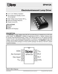
One of the standard circuits used to generate a low-pass, highpass,<br />
or band-pass filter is the state variable active filter. The<br />
digital potentiometer allows full programmability of the frequency,<br />
gain and Q of the filter outputs. Figure 10 shows the filter circuit<br />
using a 2.5 V virtual ground, which allows a ±2.5 V P input and<br />
output swing. RDAC2 and 3 set the LP, HP, and BP cutoff and<br />
center frequencies, respectively. These variable resistors should<br />
be programmed with the same data (as with ganged potentiometers)<br />
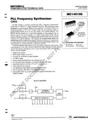
to maintain the best circuit Q. Figure 11 shows the measured<br />
filter response at the band-pass output as a function of the RDAC2<br />
and RDAC3 settings which produce a range of center frequencies<br />
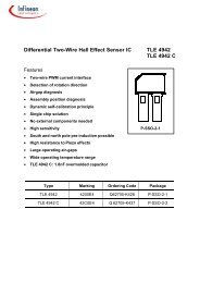
from 2 kHz to 20 kHz. The filter gain response at the band-pass<br />
output is shown in Figure 12. At a center frequency of 2 kHz, the<br />
gain is adjusted over a –20 dB to +20 dB range determined by<br />
RDAC1. Circuit Q is adjusted by RDAC4. For more detailed<br />
reading on the state variable active filter, see Analog Devices’<br />
application note, AN-318.<br />
AMPLITUDE – dB<br />
40<br />
20<br />
0<br />
–20<br />
–40<br />
–60<br />
–0.16 20.0000 k<br />
A<br />
–80 20 100 1k 10k 100k 200k<br />
FREQUENCY – Hz<br />
Figure 11. Programmed Center Frequency Band-Pass<br />
Response<br />
V IN<br />
B RDAC1<br />
A1<br />
RDAC4<br />
B<br />
10k<br />
10k<br />
B<br />
A2<br />
RDAC2<br />
OP279 2<br />
0.01F<br />
A3<br />
B<br />
RDAC3<br />
0.01F<br />
A4<br />
LOW-<br />
PASS<br />
BAND-<br />
PASS<br />
AMPLITUDE – dB<br />
40<br />
20<br />
0<br />
–20<br />
–40<br />
–19.01 2.00000 k<br />
A<br />
HIGH-<br />
PASS<br />
–60<br />
Figure 10. Programmable State Variable Active Filter<br />
–80<br />
20 100 1k 10k<br />
100k 200k<br />
FREQUENCY – Hz<br />
Figure 12. Programmed Amplitude Band-Pass Response<br />
REV. C<br />
–17–