AD8400/AD8402/AD8403 - SP-Elektroniikka
AD8400/AD8402/AD8403 - SP-Elektroniikka
AD8400/AD8402/AD8403 - SP-Elektroniikka

Create successful ePaper yourself
Turn your PDF publications into a flip-book with our unique Google optimized e-Paper software.
<strong>AD8400</strong>/<strong>AD8402</strong>/<strong>AD8403</strong><br />
Table II. Input Logic Control Truth Table<br />
CLK CS RS SHDN Register Activity<br />
L L H H No SR effect, enables SDO pin.<br />
P L H H Shift one bit in from the SDI pin.<br />
The tenth previously entered bit is<br />
shifted out of the SDO pin.<br />
X P H H Load SR data into RDAC latch<br />
based on A1, A0 decode (Table III).<br />
X H H H No Operation<br />
X X L H Sets all RDAC latches to midscale,<br />
wiper centered, and SDO latch<br />
cleared.<br />
X H P H Latches all RDAC latches to 80 H .<br />
X H H L Open circuits all resistor<br />
A-terminals, connects W to B,<br />
turns off SDO output transistor.<br />
NOTE<br />
P = positive edge, X = don’t care, SR = shift register.<br />
The serial data-output (SDO) pin contains an open drain n-channel<br />
FET. This output requires a pull-up resistor in order to transfer data<br />
to the next package’s SDI pin. The pull-up resistor termination<br />
voltage may be larger than the V DD supply (but less than max<br />
V DD of 8 V) of the <strong>AD8403</strong> SDO output device, e.g., the <strong>AD8403</strong><br />
could operate at V DD = 3.3 V and the pull-up for interface to the<br />
next device could be set at 5 V. This allows for daisy-chaining<br />
several RDACs from a single processor serial data line. The<br />
clock period needs to be increased when using a pull-up resistor<br />
to the SDI pin of the following device in the series. Capacitive<br />
loading at the daisy-chain node SDO–SDI between devices must<br />
be accounted for to successfully transfer data. When daisy chaining<br />
is used, the CS should be kept low until all the bits of every package<br />
are clocked into their respective serial registers ensuring that the<br />
address bits and data bits are in the proper decoding location.<br />
This would require 20 bits of address and data complying to the<br />
word format provided in Table I if two <strong>AD8403</strong> four-channel<br />
RDACs are daisy-chained. Note, only the <strong>AD8403</strong> has a SDO<br />
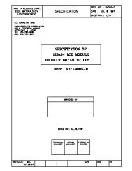
pin. During shutdown SHDN the SDO output pin is forced to<br />
the off (logic high) state to disable power dissipation in the pull-up<br />
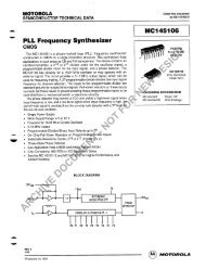
resistor. See Figure 6 for equivalent SDO output circuit schematic.<br />
The data setup and data hold times in the specification table<br />
determine the data valid time requirements. The last 10 bits of<br />
the data word entered into the serial register are held when CS<br />
returns high. At the same time CS goes high it gates the address<br />
decoder, which enables one of the two (<strong>AD8402</strong>) or four (<strong>AD8403</strong>)<br />
positive edge triggered RDAC latches. See Figure 5 detail and<br />
Table III Address Decode Table.<br />
Table III. Address Decode Table<br />
A1 A0 Latch Decoded<br />
0 0 RDAC#1<br />
0 1 RDAC#2<br />
1 0 RDAC#3 <strong>AD8403</strong> Only<br />
1 1 RDAC#4 <strong>AD8403</strong> Only<br />
CS<br />
CLK<br />
SDI<br />
<strong>AD8403</strong><br />
ADDR<br />
DECODE<br />
SERIAL<br />
REGISTER<br />
RDAC 1<br />
RDAC 2<br />
RDAC 4<br />
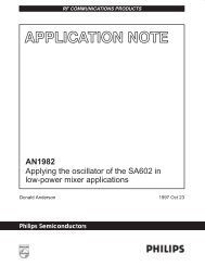
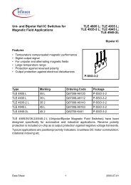
Figure 5. Equivalent Input Control Logic<br />
The target RDAC latch is loaded with the last eight bits of the<br />
serial data word completing one DAC update. In the case of the<br />
<strong>AD8403</strong> four separate 10-bit data words must be clocked in to<br />
change all four VR settings.<br />
SHDN<br />
CS<br />
SDI<br />
CLK<br />
RS<br />
SERIAL<br />
REGISTER<br />
D<br />
Q<br />
CK RS<br />
SDO<br />
Figure 6. Detail SDO Output Schematic of the <strong>AD8403</strong><br />
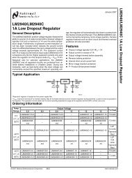
All digital pins are protected with a series input resistor and<br />
parallel Zener ESD structure shown in Figure 7a. This structure<br />
applies to digital pins CS, SDI, SDO, RS, SHDN, CLK. The<br />
digital input ESD protection allows for mixed power supply<br />
applications where 5 V CMOS logic can be used to drive an<br />
<strong>AD8400</strong>, <strong>AD8402</strong>, or <strong>AD8403</strong> operating from a 3 V power supply.<br />
The analog pins A, B, and W are protected with a 20 Ω<br />
series resistor and parallel Zener (see Figure 7b).<br />
DIGITAL<br />
PINS<br />
1k<br />
LOGIC<br />
Figure 7a. Equivalent ESD Protection Circuits<br />
A, B, W<br />
20<br />
Figure 7b. Equivalent ESD Protection Circuit<br />
(Analog Pins)<br />
A<br />
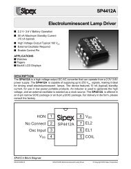
C A<br />
C A = 90.4pF (DW / 256) + 30pF<br />
RDAC<br />
10k<br />
W<br />
C W<br />
120pF<br />
C B<br />
B<br />
C B = 90.4pF [1 – (DW / 256)] + 30pF<br />
Figure 8. RDAC Circuit Simulation Model for<br />
RDAC = 10 kΩ<br />
REV. C<br />
–15–