LM117/LM317A/LM317 3-Terminal Adjustable ... - SP-Elektroniikka
LM117/LM317A/LM317 3-Terminal Adjustable ... - SP-Elektroniikka
LM117/LM317A/LM317 3-Terminal Adjustable ... - SP-Elektroniikka

You also want an ePaper? Increase the reach of your titles
YUMPU automatically turns print PDFs into web optimized ePapers that Google loves.
<strong>LM117</strong>/<strong><strong>LM317</strong>A</strong>/<strong>LM317</strong><br />
3-<strong>Terminal</strong> <strong>Adjustable</strong> Regulator<br />
General Description<br />
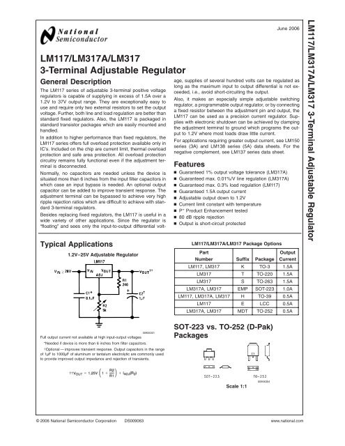
Typical Applications<br />
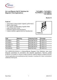
1.2V–25V <strong>Adjustable</strong> Regulator<br />
The <strong>LM117</strong> series of adjustable 3-terminal positive voltage<br />
regulators is capable of supplying in excess of 1.5A over a<br />
1.2V to 37V output range. They are exceptionally easy to<br />
use and require only two external resistors to set the output<br />
voltage. Further, both line and load regulation are better than<br />
standard fixed regulators. Also, the <strong>LM117</strong> is packaged in<br />
standard transistor packages which are easily mounted and<br />
handled.<br />
In addition to higher performance than fixed regulators, the<br />
<strong>LM117</strong> series offers full overload protection available only in<br />
IC’s. Included on the chip are current limit, thermal overload<br />
protection and safe area protection. All overload protection<br />
circuitry remains fully functional even if the adjustment terminal<br />
is disconnected.<br />
Normally, no capacitors are needed unless the device is<br />
situated more than 6 inches from the input filter capacitors in<br />
which case an input bypass is needed. An optional output<br />
capacitor can be added to improve transient response. The<br />
adjustment terminal can be bypassed to achieve very high<br />
ripple rejection ratios which are difficult to achieve with standard<br />
3-terminal regulators.<br />
Besides replacing fixed regulators, the <strong>LM117</strong> is useful in a<br />
wide variety of other applications. Since the regulator is<br />
“floating” and sees only the input-to-output differential voltage,<br />
supplies of several hundred volts can be regulated as<br />
long as the maximum input to output differential is not exceeded,<br />
i.e., avoid short-circuiting the output.<br />
Also, it makes an especially simple adjustable switching<br />
regulator, a programmable output regulator, or by connecting<br />
a fixed resistor between the adjustment pin and output, the<br />
<strong>LM117</strong> can be used as a precision current regulator. Supplies<br />
with electronic shutdown can be achieved by clamping<br />
the adjustment terminal to ground which programs the output<br />
to 1.2V where most loads draw little current.<br />
For applications requiring greater output current, see LM150<br />
series (3A) and LM138 series (5A) data sheets. For the<br />
negative complement, see LM137 series data sheet.<br />
Features<br />
n Guaranteed 1% output voltage tolerance (<strong><strong>LM317</strong>A</strong>)<br />
n Guaranteed max. 0.01%/V line regulation (<strong><strong>LM317</strong>A</strong>)<br />
n Guaranteed max. 0.3% load regulation (<strong>LM117</strong>)<br />
n Guaranteed 1.5A output current<br />
n <strong>Adjustable</strong> output down to 1.2V<br />
n Current limit constant with temperature<br />
n P + Product Enhancement tested<br />
n 80 dB ripple rejection<br />
n Output is short-circuit protected<br />
<strong>LM117</strong>/<strong><strong>LM317</strong>A</strong>/<strong>LM317</strong> Package Options<br />
Part<br />
Number Suffix Package<br />
June 2006<br />
Output<br />
Current<br />
<strong>LM117</strong>, <strong>LM317</strong> K TO-3 1.5A<br />
<strong>LM317</strong> T TO-220 1.5A<br />
<strong>LM317</strong> S TO-263 1.5A<br />
<strong><strong>LM317</strong>A</strong>, <strong>LM317</strong> EMP SOT-223 1.0A<br />
<strong>LM117</strong>, <strong><strong>LM317</strong>A</strong>, <strong>LM317</strong> H TO-39 0.5A<br />
<strong>LM117</strong> E LCC 0.5A<br />
<strong><strong>LM317</strong>A</strong>, <strong>LM317</strong> MDT TO-252 0.5A<br />
<strong>LM117</strong>/<strong><strong>LM317</strong>A</strong>/<strong>LM317</strong> 3-<strong>Terminal</strong> <strong>Adjustable</strong> Regulator<br />
00906301<br />
Full output current not available at high input-output voltages<br />
*Needed if device is more than 6 inches from filter capacitors.<br />
†Optional — improves transient response. Output capacitors in the range<br />
of 1µF to 1000µF of aluminum or tantalum electrolytic are commonly used<br />
to provide improved output impedance and rejection of transients.<br />
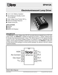
SOT-223 vs. TO-252 (D-Pak)<br />
Packages<br />
Scale 1:1<br />
00906354<br />
© 2006 National Semiconductor Corporation DS009063 www.national.com
<strong>LM117</strong>/<strong><strong>LM317</strong>A</strong>/<strong>LM317</strong><br />
Connection Diagrams<br />
TO-3 (K)<br />
Metal Can Package<br />
TO-39 (H)<br />
Metal Can Package<br />
00906330<br />
CASE IS OUTPUT<br />
Bottom View<br />
Steel Package<br />
NS Package Number K02A or K02C<br />
TO-263 (S)<br />
Surface-Mount Package<br />
00906331<br />
CASE IS OUTPUT<br />
Bottom View<br />
NS Package Number H03A<br />
TO-220 (T)<br />
Plastic Package<br />
Top View<br />
00906335<br />
00906332<br />
Front View<br />
NS Package Number T03B<br />
TO-263 (S)<br />
Surface-Mount Package<br />
Ceramic Leadless<br />
Chip Carrier (E)<br />
00906336<br />
Side View<br />
NS Package Number TS3B<br />
00906334<br />
Top View<br />
NS Package Number E20A<br />
www.national.com 2
Connection Diagrams (Continued)<br />
4-Lead SOT-223 (EMP)<br />
00906359<br />
Front View<br />
NS Package Number MP04A<br />
TO-252 (MDT)<br />
<strong>LM117</strong>/<strong><strong>LM317</strong>A</strong>/<strong>LM317</strong><br />
Front View<br />
NS Package Number TD03B<br />
00906366<br />
Ordering Information<br />
Package<br />
TO-3<br />
Metal<br />
Can (K)<br />
TO-220<br />
3- Lead<br />
TO-263<br />
3- Lead<br />
SOT-223<br />
4- Lead<br />
Temperature<br />
Range<br />
Output<br />
Current<br />
Order<br />
Number<br />
Package<br />
Marking<br />
Transport<br />
Media<br />
NSC<br />
Drawing<br />
−55˚C ≤ T J ≤ +150˚C 1.5A <strong>LM117</strong>K STEEL <strong>LM117</strong>K STEEL P+ 50 Per Bag<br />
K02A<br />
0˚C ≤ T J ≤ +125˚C 1.5A <strong>LM317</strong>K STEEL <strong>LM317</strong>K STEEL P+ 50 Per Bag<br />
−55˚C ≤ T J ≤ +150˚C 1.5A <strong>LM117</strong>K/883 <strong>LM117</strong>K/883 50 Per Bag K02C<br />
−40˚C ≤ T J ≤ +125˚C 1.5A <strong><strong>LM317</strong>A</strong>T <strong><strong>LM317</strong>A</strong>T P+ 45 Units/Rail<br />
0˚C ≤ T J ≤ +125˚C 1.5A <strong>LM317</strong>T <strong>LM317</strong>T P+ 45 Units/Rail<br />
0˚C ≤ T J ≤ +125˚C 1.5A<br />
0˚C ≤ T J ≤ +125˚C 1.0A<br />
−40˚C ≤ T J ≤ +125˚C 1.0A<br />
<strong>LM317</strong>S<br />
<strong>LM317</strong>SX<br />
<strong>LM317</strong>EMP<br />
<strong>LM317</strong>EMPX<br />
<strong><strong>LM317</strong>A</strong>EMP<br />
<strong><strong>LM317</strong>A</strong>EMPX<br />
<strong>LM317</strong>S P+<br />
N01A<br />
N07A<br />
45 Units/Rail<br />
500 Units Tape and Reel<br />
1k Units Tape and Reel<br />
2k Units Tape and Reel<br />
1k Units Tape and Reel<br />
2k Units Tape and Reel<br />
T03B<br />
TS3B<br />
MP04A<br />
−55˚C ≤ T J ≤ +150˚C 0.5A <strong>LM117</strong>H <strong>LM117</strong>H P+ 500 Per Box<br />
TO-39<br />
−55˚C ≤ T J ≤ +150˚C 0.5A <strong>LM117</strong>H/883 <strong>LM117</strong>H/883 20 Per Tray<br />
Metal<br />
H03A<br />
−40˚C ≤ T<br />
Can (H)<br />
J ≤ +125˚C 0.5A <strong><strong>LM317</strong>A</strong>H <strong><strong>LM317</strong>A</strong>H P+ 500 Per Box<br />
0˚C ≤ T J ≤ +125˚C 0.5A <strong>LM317</strong>H <strong>LM317</strong>H P+ 500 Per Box<br />
LCC −55˚C ≤ T J ≤ +150˚C 0.5A <strong>LM117</strong>E/883 <strong>LM117</strong>E/883 50 Units/Rail E20A<br />
TO-252<br />
3- Lead<br />
D-Pack<br />
0˚C ≤ T J ≤ +125˚C 0.5A<br />
−40˚C ≤ T J ≤ +125˚C 0.5A<br />
<strong>LM317</strong>MDT<br />
<strong>LM317</strong>MDTX<br />
<strong><strong>LM317</strong>A</strong>MDT<br />
<strong><strong>LM317</strong>A</strong>MDTX<br />
<strong>LM317</strong>MDT<br />
<strong><strong>LM317</strong>A</strong>MDT<br />
75 Units/Rail<br />
2.5k Units Tape and Reel<br />
75 Units/Rail<br />
2.5k Units Tape and Reel<br />
TD03B<br />
3<br />
www.national.com
<strong>LM117</strong>/<strong><strong>LM317</strong>A</strong>/<strong>LM317</strong><br />
Absolute Maximum Ratings (Note 1)<br />
If Military/Aerospace specified devices are required,<br />
please contact the National Semiconductor Sales Office/<br />
Distributors for availability and specifications.<br />
Power Dissipation<br />
Internally Limited<br />
Input-Output Voltage Differential<br />
+40V, −0.3V<br />
Storage Temperature<br />
−65˚C to +150˚C<br />
Lead Temperature<br />
Metal Package (Soldering, 10 seconds) 300˚C<br />
Plastic Package (Soldering, 4 seconds) 260˚C<br />
ESD Tolerance (Note 5)<br />
3 kV<br />
Operating Temperature Range<br />
<strong>LM117</strong><br />
−55˚C ≤ T J ≤ +150˚C<br />
<strong><strong>LM317</strong>A</strong><br />
−40˚C ≤ T J ≤ +125˚C<br />
<strong>LM317</strong><br />
0˚C ≤ T J ≤ +125˚C<br />
Preconditioning<br />
Thermal Limit Burn-In All Devices 100%<br />
<strong>LM117</strong> Electrical Characteristics(Note 3)<br />
Specifications with standard type face are for T J = 25˚C, and those with boldface type apply over full Operating Temperature<br />
Range. Unless otherwise specified, V IN −V OUT = 5V, and I OUT =10mA.<br />
Parameter<br />
Reference Voltage<br />
Conditions<br />
Line Regulation 3V ≤ (V IN −V OUT ) ≤ 40V (Note 4)<br />
Load Regulation 10 mA ≤ I OUT ≤ I MAX (Note 4)<br />
<strong>LM117</strong> (Note 2)<br />
Min Typ Max Units<br />
3V ≤ (V IN −V OUT ) ≤ 40V,<br />
10 mA ≤ I OUT ≤ I MAX<br />
1.20 1.25 1.30 V<br />
Thermal Regulation 20 ms Pulse 0.03 0.07 %/W<br />
Adjustment Pin Current 50 100 µA<br />
Adjustment Pin Current Change<br />
10 mA ≤ I OUT ≤ I MAX<br />
3V ≤ (V IN −V OUT ) ≤ 40V<br />
0.2 5 µA<br />
Temperature Stability T MIN ≤ T J ≤ T MAX 1 %<br />
Minimum Load Current (V IN −V OUT ) = 40V 3.5 5 mA<br />
(V IN −V OUT ) ≤ 15V<br />
K Package<br />
1.5 2.2 3.4<br />
A<br />
H, E Package<br />
0.5 0.8 1.8<br />
Current Limit<br />
(V IN −V OUT ) = 40V<br />
K Package<br />
0.3 0.4<br />
A<br />
H, E Package<br />
0.15 0.20<br />
RMS Output Noise, % of V OUT 10 Hz ≤ f ≤ 10 kHz 0.003 %<br />
V OUT = 10V, f = 120 Hz,<br />
65 dB<br />
C ADJ =0µF<br />
Ripple Rejection Ratio<br />
V OUT = 10V, f = 120 Hz,<br />
66 80 dB<br />
C ADJ =10µF<br />
Long-Term Stability T J = 125˚C, 1000 hrs 0.3 1 %<br />
Thermal Resistance, θ JC<br />
Junction-to-Case<br />
Thermal Resistance, θ JA<br />
Junction-to-Ambient<br />
(No Heat Sink)<br />
K (TO-3) Package<br />
H (TO-39) Package<br />
E (LCC) Package<br />
K (TO-3) Package<br />
H (TO-39) Package<br />
E (LCC) Package<br />
0.01<br />
0.02<br />
0.1<br />
0.3<br />
2<br />
21<br />
12<br />
39<br />
186<br />
88<br />
0.02<br />
0.05<br />
0.3<br />
1<br />
%/V<br />
%<br />
˚C/W<br />
˚C/W<br />
www.national.com 4
<strong><strong>LM317</strong>A</strong> and <strong>LM317</strong> Electrical Characteristics(Note 3)<br />
Specifications with standard type face are for T J = 25˚C, and those with boldface type apply over full Operating Temperature<br />
Range. Unless otherwise specified, V IN −V OUT = 5V, and I OUT =10mA.<br />
Parameter<br />
Reference Voltage<br />
Conditions<br />
<strong><strong>LM317</strong>A</strong><br />
<strong>LM317</strong><br />
Min Typ Max Min Typ Max Units<br />
1.238 1.250 1.262 - 1.25 - V<br />
3V ≤ (V IN −V OUT ) ≤ 40V,<br />
10 mA ≤ I OUT ≤ I MAX<br />
1.225 1.250 1.270 1.20 1.25 1.30 V<br />
Line Regulation 3V ≤ (V IN −V OUT ) ≤ 40V (Note 4)<br />
Load Regulation 10 mA ≤ I OUT ≤ I MAX (Note 4)<br />
Thermal Regulation 20 ms Pulse 0.04 0.07 0.04 0.07 %/W<br />
Adjustment Pin Current 50 100 50 100 µA<br />
0.005<br />
0.01<br />
0.1<br />
0.3<br />
0.01<br />
0.02<br />
0.5<br />
1<br />
0.01<br />
0.02<br />
0.1<br />
0.3<br />
0.04<br />
0.07<br />
0.5<br />
1.5<br />
%/V<br />
%<br />
<strong>LM117</strong>/<strong><strong>LM317</strong>A</strong>/<strong>LM317</strong><br />
Adjustment Pin Current Change<br />
10 mA ≤ I OUT ≤ I MAX<br />
3V ≤ (V IN −V OUT ) ≤ 40V<br />
0.2 5 0.2 5 µA<br />
Temperature Stability T MIN ≤ T J ≤ T MAX 1 1 %<br />
Minimum Load Current (V IN −V OUT ) = 40V 3.5 10 3.5 10 mA<br />
(V IN −V OUT ) ≤ 15V<br />
K, T, S Packages<br />
EMP Package<br />
-<br />
1.0<br />
-<br />
1.5<br />
-<br />
2.6<br />
1.5<br />
1.0<br />
2.2<br />
1.5<br />
3.4<br />
2.6 A<br />
Current Limit<br />
H, MDT Packages<br />
0.5 0.8 1.8 0.5 0.8 1.8<br />
(V IN −V OUT ) = 40V<br />
K, T, S Packages<br />
EMP Package<br />
-<br />
0.112<br />
-<br />
0.30<br />
0.15<br />
0.112<br />
0.40<br />
0.30<br />
A<br />
H, MDT Packages<br />
0.075 0.20<br />
0.075 0.20<br />
RMS Output Noise, % of V OUT 10 Hz ≤ f ≤ 10 kHz 0.003 0.003 %<br />
V OUT = 10V, f = 120 Hz,<br />
65 65 dB<br />
C ADJ =0µF<br />
Ripple Rejection Ratio<br />
V OUT = 10V, f = 120 Hz,<br />
66 80 66 80 dB<br />
C ADJ =10µF<br />
Long-Term Stability T J = 125˚C, 1000 hrs 0.3 1 0.3 1 %<br />
Thermal Resistance, θ JC<br />
Junction-to-Case<br />
Thermal Resistance, θ JA<br />
Junction-to-Ambient<br />
(No Heat Sink)<br />
K (TO-3) Package<br />
T (TO-220) Package<br />
S (TO-263) Package<br />
EMP (SOT-223) Package<br />
H (TO-39) Package<br />
MDT (TO-252) Package<br />
K (TO-3) Package<br />
T (TO-220) Package<br />
S (TO-263) Package (Note 6)<br />
EMP (SOT-223) Package (Note 6)<br />
H (TO-39) Package<br />
MDT (TO-252) Package (Note 6)<br />
Note 1: Absolute Maximum Ratings indicate limits beyond which damage to the device may occur. Operating Ratings indicate conditions for which the device is<br />
intended to be functional, but do not guarantee specific performance limits. For guaranteed specifications and test conditions, see the Electrical Characteristics. The<br />
guaranteed specifications apply only for the test conditions listed.<br />
Note 2: Refer to RETS117H drawing for the <strong>LM117</strong>H, or the RETS117K for the <strong>LM117</strong>K military specifications.<br />
Note 3: I MAX = 1.5A for the K (TO-3), T (TO-220), and S (TO-263) packages. I MAX = 1.0A for the EMP (SOT-223) package. I MAX = 0.5A for the H (TO-39), MDT<br />
(TO-252), and E (LCC) packages. Device power dissipation (P D ) is limited by ambient temperature (T A ), device maximum junction temperature (T J ), and package<br />
thermal resistance (θ JA ). The maximum allowable power dissipation at any temperature is : P D(MAX) = ((T J(MAX) -T A )/θ JA ). All Min. and Max. limits are guaranteed<br />
to National’s Average Outgoing Quality Level (AOQL).<br />
Note 4: Regulation is measured at a constant junction temperature, using pulse testing with a low duty cycle. Changes in output voltage due to heating effects are<br />
covered under the specifications for thermal regulation.<br />
Note 5: Human body model, 100 pF discharged through a 1.5 kΩ resistor.<br />
Note 6: When surface mount packages are used (TO-263, SOT-223, TO-252), the junction to ambient thermal resistance can be reduced by increasing the PC<br />
board copper area that is thermally connected to the package. See the Applications Hints section for heatsink techniques.<br />
-<br />
-<br />
-<br />
23.5<br />
21<br />
12<br />
-<br />
-<br />
-<br />
140<br />
186<br />
103<br />
2<br />
4<br />
4<br />
23.5<br />
21<br />
12<br />
39<br />
50<br />
50<br />
140<br />
186<br />
103<br />
˚C/W<br />
˚C/W<br />
5<br />
www.national.com
<strong>LM117</strong>/<strong><strong>LM317</strong>A</strong>/<strong>LM317</strong><br />
Typical Performance Characteristics Output Capacitor =0µFunless otherwise noted<br />
Load Regulation<br />
Current Limit<br />
00906337 00906338<br />
Adjustment Current<br />
Dropout Voltage<br />
00906339 00906340<br />
Temperature Stability<br />
Minimum Operating Current<br />
00906341 00906342<br />
www.national.com 6
Typical Performance Characteristics Output Capacitor =0µFunless otherwise noted (Continued)<br />
Ripple Rejection<br />
Ripple Rejection<br />
<strong>LM117</strong>/<strong><strong>LM317</strong>A</strong>/<strong>LM317</strong><br />
00906343 00906344<br />
Ripple Rejection<br />
Output Impedance<br />
00906345 00906346<br />
Line Transient Response<br />
Load Transient Response<br />
00906347 00906348<br />
7<br />
www.national.com
<strong>LM117</strong>/<strong><strong>LM317</strong>A</strong>/<strong>LM317</strong><br />
Application Hints<br />
In operation, the <strong>LM117</strong> develops a nominal 1.25V reference<br />
voltage, V REF , between the output and adjustment terminal.<br />
The reference voltage is impressed across program resistor<br />
R1 and, since the voltage is constant, a constant current I 1<br />
then flows through the output set resistor R2, giving an<br />
output voltage of<br />
(1)<br />
can cause excessive ringing. This occurs with values between<br />
500 pF and 5000 pF. A 1 µF solid tantalum (or 25 µF<br />
aluminum electrolytic) on the output swamps this effect and<br />
insures stability. Any increase of the load capacitance larger<br />
than 10 µF will merely improve the loop stability and output<br />
impedance.<br />
LOAD REGULATION<br />
The <strong>LM117</strong> is capable of providing extremely good load<br />
regulation but a few precautions are needed to obtain maximum<br />
performance. The current set resistor connected between<br />
the adjustment terminal and the output terminal (usually<br />
240Ω) should be tied directly to the output (case) of the<br />
regulator rather than near the load. This eliminates line<br />
drops from appearing effectively in series with the reference<br />
and degrading regulation. For example, a 15V regulator with<br />
0.05Ω resistance between the regulator and load will have a<br />
load regulation due to line resistance of 0.05Ω xI L . If the set<br />
resistor is connected near the load the effective line resistance<br />
will be 0.05Ω (1 + R2/R1) or in this case, 11.5 times<br />
worse.<br />
Figure 2 shows the effect of resistance between the regulator<br />
and 240Ω set resistor.<br />
00906305<br />
FIGURE 1.<br />
Since the 100µA current from the adjustment terminal represents<br />
an error term, the <strong>LM117</strong> was designed to minimize<br />
I ADJ and make it very constant with line and load changes.<br />
To do this, all quiescent operating current is returned to the<br />
output establishing a minimum load current requirement. If<br />
there is insufficient load on the output, the output will rise.<br />
EXTERNAL CAPACITORS<br />
An input bypass capacitor is recommended. A 0.1µF disc or<br />
1µF solid tantalum on the input is suitable input bypassing<br />
for almost all applications. The device is more sensitive to<br />
the absence of input bypassing when adjustment or output<br />
capacitors are used but the above values will eliminate the<br />
possibility of problems.<br />
The adjustment terminal can be bypassed to ground on the<br />
<strong>LM117</strong> to improve ripple rejection. This bypass capacitor<br />
prevents ripple from being amplified as the output voltage is<br />
increased. With a 10 µF bypass capacitor 80dB ripple rejection<br />
is obtainable at any output level. Increases over 10 µF<br />
do not appreciably improve the ripple rejection at frequencies<br />
above 120Hz. If the bypass capacitor is used, it is<br />
sometimes necessary to include protection diodes to prevent<br />
the capacitor from discharging through internal low current<br />
paths and damaging the device.<br />
In general, the best type of capacitors to use is solid tantalum.<br />
Solid tantalum capacitors have low impedance even at<br />
high frequencies. Depending upon capacitor construction, it<br />
takes about 25 µF in aluminum electrolytic to equal 1µF solid<br />
tantalum at high frequencies. Ceramic capacitors are also<br />
good at high frequencies; but some types have a large<br />
decrease in capacitance at frequencies around 0.5 MHz. For<br />
this reason, 0.01 µF disc may seem to work better than a 0.1<br />
µF disc as a bypass.<br />
Although the <strong>LM117</strong> is stable with no output capacitors, like<br />
any feedback circuit, certain values of external capacitance<br />
00906306<br />
FIGURE 2. Regulator with Line Resistance in Output<br />
Lead<br />
With the TO-3 package, it is easy to minimize the resistance<br />
from the case to the set resistor, by using two separate leads<br />
to the case. However, with the TO-39 package, care should<br />
be taken to minimize the wire length of the output lead. The<br />
ground of R2 can be returned near the ground of the load to<br />
provide remote ground sensing and improve load regulation.<br />
PROTECTION DIODES<br />
When external capacitors are used with any IC regulator it is<br />
sometimes necessary to add protection diodes to prevent<br />
the capacitors from discharging through low current points<br />
into the regulator. Most 10 µF capacitors have low enough<br />
internal series resistance to deliver 20A spikes when<br />
shorted. Although the surge is short, there is enough energy<br />
to damage parts of the IC.<br />
When an output capacitor is connected to a regulator and<br />
the input is shorted, the output capacitor will discharge into<br />
the output of the regulator. The discharge current depends<br />
on the value of the capacitor, the output voltage of the<br />
regulator, and the rate of decrease of V IN . In the <strong>LM117</strong>, this<br />
discharge path is through a large junction that is able to<br />
sustain 15A surge with no problem. This is not true of other<br />
types of positive regulators. For output capacitors of 25 µF or<br />
less, there is no need to use diodes.<br />
The bypass capacitor on the adjustment terminal can discharge<br />
through a low current junction. Discharge occurs<br />
www.national.com 8
Application Hints (Continued)<br />
when either the input, or the output, is shorted. Internal to the<br />
<strong>LM117</strong> is a 50Ω resistor which limits the peak discharge<br />
current. No protection is needed for output voltages of 25V<br />
or less and 10 µF capacitance. Figure 3 shows an <strong>LM117</strong><br />
with protection diodes included for use with outputs greater<br />
than 25V and high values of output capacitance.<br />
<strong>LM117</strong>/<strong><strong>LM317</strong>A</strong>/<strong>LM317</strong><br />
00906360<br />
D1 protects against C1<br />
D2 protects against C2<br />
00906307<br />
(2)<br />
FIGURE 4. Power Dissipation Diagram<br />
If the calculated maximum allowable thermal resistance is<br />
higher than the actual package rating, then no additional<br />
work is needed. If the calculated maximum allowable thermal<br />
resistance is lower than the actual package rating either<br />
the power dissipation (P D ) needs to be reduced, the maximum<br />
ambient temperature T A(MAX) needs to be reduced, the<br />
thermal resistance (θ JA ) must be lowered by adding a heatsink,<br />
or some combination of these.<br />
If a heatsink is needed, the value can be calculated from the<br />
formula:<br />
θ HA ≤ (θ JA -(θ CH + θ JC )) (6)<br />
FIGURE 3. Regulator with Protection Diodes<br />
HEATSINK REQUIREMENTS<br />
The <strong>LM317</strong> regulators have internal thermal shutdown to<br />
protect the device from over-heating. Under all operating<br />
conditions, the junction temperature of the <strong>LM317</strong> should not<br />
exceed the rated maximum junction temperature (T J ) of<br />
150˚C for the <strong>LM117</strong>, or 125˚C for the <strong><strong>LM317</strong>A</strong> and <strong>LM317</strong>.<br />
A heatsink may be required depending on the maximum<br />
device power dissipation and the maximum ambient temperature<br />
of the application. To determine if a heatsink is<br />
needed, the power dissipated by the regulator, P D , must be<br />
calculated:<br />
P D = ((V IN −V OUT )xI L )+(V IN xI G ) (3)<br />
Figure 4 shows the voltage and currents which are present in<br />
the circuit.<br />
The next parameter which must be calculated is the maximum<br />
allowable temperature rise, T R(MAX) :<br />
T R(MAX) =T J(MAX) −T A(MAX) (4)<br />
where (θ CH is the thermal resistance of the contact area<br />
between the device case and the heatsink surface, and θ JC<br />
is thermal resistance from the junction of the die to surface of<br />
the package case.<br />
When a value for θ (H−A) is found using the equation shown,<br />
a heatsink must be selected that has a value that is less<br />
than, or equal to, this number.<br />
The θ (H−A) rating is specified numerically by the heatsink<br />
manufacturer in the catalog, or shown in a curve that plots<br />
temperature rise vs power dissipation for the heatsink.<br />
HEATSINKING SURFACE MOUNT PACKAGES<br />
The TO-263 (S), SOT-223 (EMP) and TO-252 (MDT) packages<br />
use a copper plane on the PCB and the PCB itself as<br />
a heatsink. To optimize the heat sinking ability of the plane<br />
and PCB, solder the tab of the package to the plane.<br />
HEATSINKING THE SOT-223 PACKAGE<br />
Figure 5 and Figure 6 show the information for the SOT-223<br />
package. Figure 6 assumes a θ (J−A) of 74˚C/W for 1 ounce<br />
copper and 51˚C/W for 2 ounce copper and a maximum<br />
junction temperature of 125˚C. Please see AN-1028 for thermal<br />
enhancement techniques to be used with SOT-223 and<br />
TO-252 packages.<br />
where T J(MAX) is the maximum allowable junction temperature<br />
(150˚C for the <strong>LM117</strong>, or 125˚C for the <strong><strong>LM317</strong>A</strong>/<strong>LM317</strong>),<br />
and T A(MAX) is the maximum ambient temperature which will<br />
be encountered in the application.<br />
Using the calculated values for T R(MAX) and P D , the maximum<br />
allowable value for the junction-to-ambient thermal<br />
resistance (θ JA ) can be calculated:<br />
θ JA =(T R(MAX) /P D ) (5)<br />
9<br />
www.national.com
<strong>LM117</strong>/<strong><strong>LM317</strong>A</strong>/<strong>LM317</strong><br />
Application Hints (Continued)<br />
00906355<br />
00906357<br />
FIGURE 5. θ (J−A) vs Copper (2 ounce) Area for the<br />
SOT-223 Package<br />
FIGURE 7. θ (J−A) vs Copper (1 ounce) Area for the<br />
TO-263 Package<br />
As a design aid, Figure 8 shows the maximum allowable<br />
power dissipation compared to ambient temperature for the<br />
TO-263 device (assuming θ (J−A) is 35˚C/W and the maximum<br />
junction temperature is 125˚C).<br />
00906358<br />
FIGURE 6. Maximum Power Dissipation vs T AMB for<br />
the SOT-223 Package<br />
HEATSINKING THE TO-263 PACKAGE<br />
Figure 7 shows for the TO-263 the measured values of θ (J−A)<br />
for different copper area sizes using a typical PCB with 1<br />
ounce copper and no solder mask over the copper area used<br />
for heatsinking.<br />
As shown in Figure 7, increasing the copper area beyond 1<br />
square inch produces very little improvement. It should also<br />
be observed that the minimum value of θ (J−A) for the TO-263<br />
package mounted to a PCB is 32˚C/W.<br />
00906356<br />
FIGURE 8. Maximum Power Dissipation vs T AMB for<br />
the TO-263 Package<br />
HEATSINKING THE TO-252 PACKAGE<br />
If the maximum allowable value for θ JA is found to be<br />
≥103˚C/W (Typical Rated Value) for TO-252 package, no<br />
heatsink is needed since the package alone will dissipate<br />
enough heat to satisfy these requirements. If the calculated<br />
value for θ JA falls below these limits, a heatsink is required.<br />
As a design aid, Table 1 shows the value of the θ JA of<br />
TO-252 for different heatsink area. The copper patterns that<br />
we used to measure these θ JA s are shown at the end of the<br />
Application Notes Section. Figure 9 reflects the same test<br />
results as what are in Table 1.<br />
Figure 10 shows the maximum allowable power dissipation<br />
vs. ambient temperature for the TO-252 device. Figure 11<br />
shows the maximum allowable power dissipation vs. copper<br />
area (in 2 ) for the TO-252 device. Please see AN-1028 for<br />
thermal enhancement techniques to be used with SOT-223<br />
and TO-252 packages.<br />
www.national.com 10
Application Hints (Continued)<br />
TABLE 1. θ JA Different Heatsink Area<br />
Layout Copper Area Thermal Resistance<br />
Top Side (in 2 )* Bottom Side (in 2 ) (θ JA˚C/W) TO-252<br />
1 0.0123 0 103<br />
2 0.066 0 87<br />
3 0.3 0 60<br />
4 0.53 0 54<br />
5 0.76 0 52<br />
6 1.0 0 47<br />
7 0.066 0.2 84<br />
8 0.066 0.4 70<br />
9 0.066 0.6 63<br />
10 0.066 0.8 57<br />
11 0.066 1.0 57<br />
12 0.066 0.066 89<br />
13 0.175 0.175 72<br />
14 0.284 0.284 61<br />
15 0.392 0.392 55<br />
16 0.5 0.5 53<br />
<strong>LM117</strong>/<strong><strong>LM317</strong>A</strong>/<strong>LM317</strong><br />
Note: * Tab of device attached to topside of copper.<br />
00906361<br />
FIGURE 9. θ JA vs 2oz Copper Area for TO-252<br />
11<br />
www.national.com
<strong>LM117</strong>/<strong><strong>LM317</strong>A</strong>/<strong>LM317</strong><br />
Application Hints (Continued)<br />
00906363<br />
FIGURE 10. Maximum Allowable Power Dissipation vs. Ambient Temperature for TO-252<br />
00906362<br />
FIGURE 11. Maximum Allowable Power Dissipation vs. 2oz Copper Area for TO-252<br />
www.national.com 12
Application Hints (Continued)<br />
<strong>LM117</strong>/<strong><strong>LM317</strong>A</strong>/<strong>LM317</strong><br />
00906364<br />
FIGURE 12. Top View of the Thermal Test Pattern in Actual Scale<br />
13<br />
www.national.com
<strong>LM117</strong>/<strong><strong>LM317</strong>A</strong>/<strong>LM317</strong><br />
Application Hints (Continued)<br />
00906365<br />
FIGURE 13. Bottom View of the Thermal Test Pattern in Actual Scale<br />
www.national.com 14
Schematic Diagram<br />
<strong>LM117</strong>/<strong><strong>LM317</strong>A</strong>/<strong>LM317</strong><br />
00906308<br />
Typical Applications<br />
5V Logic Regulator with Electronic Shutdown*<br />
<strong>Adjustable</strong> Regulator with Improved Ripple Rejection<br />
*Min. output ) 1.2V<br />
Slow Turn-On 15V Regulator<br />
00906303<br />
†Solid tantalum<br />
*Discharges C1 if output is shorted to ground<br />
High Stability 10V Regulator<br />
00906310<br />
00906309<br />
00906311<br />
15<br />
www.national.com
<strong>LM117</strong>/<strong><strong>LM317</strong>A</strong>/<strong>LM317</strong><br />
Typical Applications (Continued)<br />
High Current <strong>Adjustable</strong> Regulator<br />
‡Optional — improves ripple rejection<br />
†Solid tantalum<br />
*Minimum load current = 30 mA<br />
00906312<br />
0 to 30V Regulator<br />
Power Follower<br />
00906313<br />
Full output current not available at high input-output voltages<br />
00906314<br />
www.national.com 16
Typical Applications (Continued)<br />
5A Constant Voltage/Constant Current Regulator<br />
<strong>LM117</strong>/<strong><strong>LM317</strong>A</strong>/<strong>LM317</strong><br />
†Solid tantalum<br />
*Lights in constant current mode<br />
00906315<br />
1A Current Regulator<br />
High Gain Amplifier<br />
00906316<br />
1.2V–20V Regulator with Minimum Program Current<br />
00906318<br />
*Minimum load current ) 4mA<br />
00906317<br />
17<br />
www.national.com
<strong>LM117</strong>/<strong><strong>LM317</strong>A</strong>/<strong>LM317</strong><br />
Typical Applications (Continued)<br />
Low Cost 3A Switching Regulator<br />
†Solid tantalum<br />
*Core — Arnold A-254168-2 60 turns<br />
00906319<br />
4A Switching Regulator with Overload Protection<br />
†Solid tantalum<br />
*Core — Arnold A-254168-2 60 turns<br />
00906320<br />
Precision Current Limiter<br />
00906321<br />
www.national.com 18
Typical Applications (Continued)<br />
Tracking Preregulator<br />
<strong>LM117</strong>/<strong><strong>LM317</strong>A</strong>/<strong>LM317</strong><br />
00906322<br />
Current Limited Voltage Regulator<br />
00906323<br />
(Compared to <strong>LM117</strong>’s higher current limit)<br />
— At 50 mA output only 3 ⁄4 volt of drop occurs in R 3 and R 4<br />
Adjusting Multiple On-Card Regulators with Single Control*<br />
*All outputs within ±100 mV<br />
†Minimum load — 10 mA<br />
00906324<br />
19<br />
www.national.com
<strong>LM117</strong>/<strong><strong>LM317</strong>A</strong>/<strong>LM317</strong><br />
Typical Applications (Continued)<br />
AC Voltage Regulator<br />
00906325<br />
12V Battery Charger<br />
00906326<br />
Use of R S allows low charging rates with fully charged battery.<br />
50mA Constant Current Battery Charger<br />
00906327<br />
www.national.com 20
Typical Applications (Continued)<br />
<strong>Adjustable</strong> 4A Regulator<br />
<strong>LM117</strong>/<strong><strong>LM317</strong>A</strong>/<strong>LM317</strong><br />
00906328<br />
Current Limited 6V Charger<br />
Digitally Selected Outputs<br />
00906329<br />
*Sets peak current (0.6A for 1Ω)<br />
**The 1000µF is recommended to filter out input transients<br />
*Sets maximum V OUT<br />
00906302<br />
21<br />
www.national.com
<strong>LM117</strong>/<strong><strong>LM317</strong>A</strong>/<strong>LM317</strong><br />
Physical Dimensions inches (millimeters) unless otherwise noted<br />
TO-3 Metal Can Package (K)<br />
NS Package Number K02A<br />
TO-3 Metal Can Package (K)<br />
Mil-Aero Product<br />
NS Package Number K02C<br />
www.national.com 22
Physical Dimensions inches (millimeters) unless otherwise noted (Continued)<br />
<strong>LM117</strong>/<strong><strong>LM317</strong>A</strong>/<strong>LM317</strong><br />
TO-39 Metal Can Package (H)<br />
NS Package Number H03A<br />
3-Lead TO-220 (T)<br />
NS Package Number T03B<br />
23<br />
www.national.com
<strong>LM117</strong>/<strong><strong>LM317</strong>A</strong>/<strong>LM317</strong><br />
Physical Dimensions inches (millimeters) unless otherwise noted (Continued)<br />
3-Lead TO-263 (S)<br />
NS Package Number TS3B<br />
Ceramic Leadless Chip Carrier (E)<br />
NS Package Number E20A<br />
www.national.com 24
Physical Dimensions inches (millimeters) unless otherwise noted (Continued)<br />
<strong>LM117</strong>/<strong><strong>LM317</strong>A</strong>/<strong>LM317</strong><br />
4-Lead SOT-223 (EMP)<br />
NS Package Number MP04A<br />
3-Lead D-Pack (MDT)<br />
NS Package Number TD03B<br />
25<br />
www.national.com
<strong>LM117</strong>/<strong><strong>LM317</strong>A</strong>/<strong>LM317</strong> 3-<strong>Terminal</strong> <strong>Adjustable</strong> Regulator<br />
Notes<br />
National does not assume any responsibility for use of any circuitry described, no circuit patent licenses are implied and National reserves<br />
the right at any time without notice to change said circuitry and specifications.<br />
For the most current product information visit us at www.national.com.<br />
LIFE SUPPORT POLICY<br />
NATIONAL’S PRODUCTS ARE NOT AUTHORIZED FOR USE AS CRITICAL COMPONENTS IN LIFE SUPPORT DEVICES OR SYSTEMS<br />
WITHOUT THE EXPRESS WRITTEN APPROVAL OF THE PRESIDENT AND GENERAL COUNSEL OF NATIONAL SEMICONDUCTOR<br />
CORPORATION. As used herein:<br />
1. Life support devices or systems are devices or systems<br />
which, (a) are intended for surgical implant into the body, or<br />
(b) support or sustain life, and whose failure to perform when<br />
properly used in accordance with instructions for use<br />
provided in the labeling, can be reasonably expected to result<br />
in a significant injury to the user.<br />
2. A critical component is any component of a life support<br />
device or system whose failure to perform can be reasonably<br />
expected to cause the failure of the life support device or<br />
system, or to affect its safety or effectiveness.<br />
BANNED SUBSTANCE COMPLIANCE<br />
National Semiconductor follows the provisions of the Product Stewardship Guide for Customers (C<strong>SP</strong>-9-111C2) and Banned Substances<br />
and Materials of Interest Specification (C<strong>SP</strong>-9-111S2) for regulatory environmental compliance. Details may be found at:<br />
www.national.com/quality/green.<br />
Lead free products are RoHS compliant.<br />
National Semiconductor<br />
Americas Customer<br />
Support Center<br />
Email: new.feedback@nsc.com<br />
Tel: 1-800-272-9959<br />
www.national.com<br />
National Semiconductor<br />
Europe Customer Support Center<br />
Fax: +49 (0) 180-530 85 86<br />
Email: europe.support@nsc.com<br />
Deutsch Tel: +49 (0) 69 9508 6208<br />
English Tel: +44 (0) 870 24 0 2171<br />
Français Tel: +33 (0) 1 41 91 8790<br />
National Semiconductor<br />
Asia Pacific Customer<br />
Support Center<br />
Email: ap.support@nsc.com<br />
National Semiconductor<br />
Japan Customer Support Center<br />
Fax: 81-3-5639-7507<br />
Email: jpn.feedback@nsc.com<br />
Tel: 81-3-5639-7560