Bedienungsanleitung / Operation Manual / Mode D'emploi - Alfra
Bedienungsanleitung / Operation Manual / Mode D'emploi - Alfra
Bedienungsanleitung / Operation Manual / Mode D'emploi - Alfra

Create successful ePaper yourself
Turn your PDF publications into a flip-book with our unique Google optimized e-Paper software.
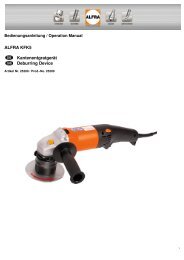
<strong>Bedienungsanleitung</strong> / <strong>Operation</strong> <strong>Manual</strong> / <strong>Mode</strong> d’emploi<br />
ALFRA ROTABEST 60<br />
Metallkernbohrmaschine<br />
Metal Core Drilling Machine<br />
Perceuse ROTABEST à socle magnétique<br />
Artikel Nr.18625 / Prod.-No. 18625 / Article Nr. 18625
Inhaltsverzeichnis / Contents / Table des matières<br />
Sicherheitshinweise, Bestimmungsgemäße Verwendung,<br />
Technische Daten, Beschreibung, Bedienung, Reinigung,<br />
Pflege, Wartung, Ersatzteilliste am Ende der<br />
<strong>Bedienungsanleitung</strong>.<br />
Safety instructions, Specified Conditions of Use, Technical<br />
Data, Description, <strong>Operation</strong>, Cleaning, Care, Maintenance,<br />
Spare Parts List at the End of <strong>Operation</strong> <strong>Manual</strong><br />
Consignes de sécurité, Conditions d’utilisation, Détails<br />
techniques, Description, Utilisation, Nettoyage, Soins,<br />
Entretien, Nomenclature des pièces de rechange à la fin de ce<br />
manuel.<br />
Vor Inbetriebnahme<br />
lesen und<br />
aufbewahren!<br />
Please read and save<br />
these instructions!<br />
À lire avant la mise en<br />
service puis à<br />
conserver !<br />
Seite 2<br />
Page 10<br />
Page 17
Sicherheitshinweise<br />
Achtung!<br />
Bei Bohren an Wänden und Decken muss die Metallkernbohrmaschine durch den mitgelieferten<br />
Sicherheitsgurt (f) abgesichert werden. Die Magnethaftkraft bleibt bei einer Stromunterbrechung nicht<br />
erhalten.<br />
Achtung!<br />
Der ausgebohrte Kern wird automatisch vom Auswerferstift (h) ausgestoßen.<br />
Der Auswerferstift kann bei unsachgemäßer Handhabung brechen.<br />
Achtung!<br />
Nur unbeschädigte Anschlussleitungen und Verlängerungsleitungen verwenden und regelmäßig auf<br />
Beschädigung überprüfen. Sonst besteht die Gefahr eines elektrischen Schlages.<br />
Achtung!<br />
Netzspannung und Spannungsangaben am Gerät müssen übereinstimmen.<br />
Achtung!<br />
Beim Arbeiten mit diesem Gerät folgende Schutzausrüstung tragen:<br />
Schutzbrille, festes Schuhwerk, Gehörschutz, Haarnetz (bei langen Haaren), ggf. auch Schürze und<br />
Helm.<br />
Achtung!<br />
Die Aufstellfläche für den Magnetfuß muss eben, sauber und rostfrei sein. Lack- und Spachtelschichten<br />
entfernen.<br />
Achtung!<br />
Keine Elektro-Schweißarbeiten an dem Werkstück ausführen, auf dem die Metallkernbohrmaschine zum<br />
Einsatz kommt.<br />
Achtung!<br />
Vor allen Arbeiten Kühlmitteleinrichtung (b) zur Unterstützung der Kühlung montieren.<br />
Bestimmungsgemäße Verwendung<br />
Dieses Gerät ist bestimmt zum Bohren mit Kernbohrern, Vollbohrern und zum Schneiden von Gewinden in<br />
wettergeschützter Umgebung, von Materialien mit magnetisierbarer Oberfläche. Es ist bestimmt für den<br />
gewerblichen Einsatz in Industrie und Handwerk. Das Gerät lässt sich waagrecht, senkrecht und über Kopf<br />
einsetzen.<br />
3
Technische Daten<br />
Artikel – Nr.: 18625<br />
Bezeichnung: ROTABEST 60<br />
Leistungsaufnahme:<br />
Lastdrehzahl:<br />
1800 Watt<br />
110/175/245/385 1 -min<br />
Werkzeugaufnahme: MK 3<br />
Spannung:<br />
Magnethaftkraft:<br />
siehe Typenschild<br />
20000 N<br />
Bohr Ø max. in Stahl:<br />
- Kernbohrer 60 mm<br />
- Spiralbohrer 32 mm<br />
Schnitttiefe:<br />
Gewindeschneiden:<br />
Hubbereich:<br />
Magnetfußgröße:<br />
50 mm<br />
bis M30<br />
190 mm<br />
80 x 230 mm<br />
4
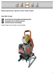
Gerätebeschreibung<br />
A ) Antriebsmotor<br />
B ) Drehkreuz<br />
C ) Bedienfeld<br />
D ) Magnetfuß<br />
E ) Bohrspindel MK 3<br />
F ) Tiefenskala<br />
G ) Inbusschrauben für Hubbereichseinstellung des Antriebmotors<br />
H ) Spannhebel für Magnetfuß<br />
J ) Aussparung für Sicherheitsgurt<br />
K ) Stellschrauben zum Justieren des Schlittens<br />
Mitgeliefertes Zubehör<br />
• Transportkasten<br />
• Kühlmitteleinrichtung<br />
• Bohrspray<br />
• Spänehaken<br />
• Sicherheitsgurt<br />
• Inbusschlüssel 2,5 mm<br />
• Inbusschlüssel 6,0 mm<br />
5
Ein- und Ausschalten<br />
• Zuerst Kabel und Stecker auf Beschädigung prüfen.<br />
• Die Taste MAGNET ON betätigen, damit der Magnet haftet und der Halt des Bohrständers gewährleistet<br />
wird. Für eine bessere Positionierung den Spannhebel (H) lösen. Jetzt ist der Bohrständer 30° nach links<br />
oder rechts schwenkbar, bzw. 10 mm nach vorne und nach hinten zu verschieben.<br />
• Für nicht magnetisierbare Materialien verwenden Sie bitte die ROTABEST Vacubest Vakuumanlage<br />
(Artikel - Nr. 18150).<br />
• Bei Arbeiten an Wänden und Decken die Bohreinheit mit Sicherheitsgurt (f) sichern. Wir empfehlen bei<br />
diesen Arbeiten das Kühlen durch ein Spray (ALFRA BIO 2000, Artikel Nr. 21010).<br />
• Antriebsmotor durch Betätigen der Taste MOTOR ON einschalten.<br />
• Ist der Magnetfuß defekt, läuft der Motor nicht an.<br />
• Das Ausschalten erfolgt in umgekehrter Reihenfolge MOTOR OFF und dann MAGNET OFF.<br />
MPI-System<br />
• Bei Funktion „Magnet an“ stehen von Beginn an 100 % der Magnetleistung zur Verfügung.<br />
• Gleichzeitig wird ein sogenanntes Zeitglied aktiviert, voreingestellt auf 60 Sekunden. Wird nach<br />
„Magnet an“ der Motor nicht zugeschalten, so blinkt die LED der Magnetschaltertaste auf der Folientastatur<br />
und es ertönt gleichzeitig ein Summton.<br />
Diese zeitgesteuerte Warnfunktion wird auch aktiviert, wenn nach dem Bohren und Abschalten des Motors<br />
der Magnet nicht abgeschaltet wird.<br />
• Eine Funktionsprüfung der LED und des Summers wird durchgeführt, wenn die Maschine über das<br />
Stromkabel über das Stromnetz verbunden wird (kurzes LED Blinken und kurzer Summton). Damit kann<br />
man vor Ort schnell und einfach das verwendete <strong>Mode</strong>ll bzw. die verwendete Schaltung gegenprüfen.<br />
• Die neuen Leiterplatten sind 100 % kompatibel mit Maschinen älterer Baureihen, d.h. im Reparaturfalle<br />
kann problemlos Ersatz bzw. Austausch erfolgen.<br />
6
Arbeiten mit Kernbohrer (Weldonschaft)<br />
• Werkzeughalter AMK 3 in Bohrspindel montieren<br />
• Auswerferstift (Zentrierstift) durch den Kernbohrerkopf schieben.<br />
• Montage der ALFRA ROTABEST Kernbohrer nach Zeichnung. Gewindestift muß Mitnehmerfläche am<br />
Kernbohrer mittig treffen. Fest anziehen.<br />
• Zuerst den Kernbohrer mit Auswerferstift auf einen angekörnten Punkt oder Anriss ausrichten und<br />
aufsetzen.<br />
• Den Kernbohrer aufsetzten und Werkstück anbohren bis die ganze Schnittfläche als Kreisring ausgebildet<br />
ist. Das Bohren mit ALFRA ROTABEST Kernbohrern erfordert keinen großen Kraftaufwand.<br />
• Während des Bohrvorgangs sollte der Kernbohrer ständig gekühlt werden. Optimale Kühlung ist durch<br />
unsere Kühlmitteleinrichtung mittels Innenkühlung möglich.<br />
• Während des Bohrens den Antriebsmotor nicht abschalten. Nach dem Bohrvorgang Kernbohrer bei<br />
laufendem Motor zurückziehen.<br />
• Nach jedem Bohren Späne und Kern entfernen.<br />
Achtung!<br />
Späne mit Spänehaken entfernen. Nicht mit bloßer Hand anfassen. Verletzungsgefahr!<br />
Arbeiten mit Vollbohrer<br />
• Das Zahnkranzbohrfutter 3-16 mm mit MK 3 Schaft ist nur zum Bohren mit Spiralbohrern geeignet.<br />
• Bohrfutter mit Adapter in die Bohrspindel einsetzen.<br />
• Spiralbohrer in Bohrfutter einsetzen und mit Bohrfutterschlüssel fest spannen.<br />
• Spiralbohrer mit MK 3 Schaft können direkt in die Bohrspindel eingesetzt werden.<br />
7
Gewindeschneiden<br />
Mit den Gewindeschneidapparaten besteht die Möglichkeit Gewinde von M3 bis M30 zu schneiden. Der<br />
Gewindeschneidapparat schaltet automatisch auf Linkslauf um, sobald das Drehkreuz (B) zurückgedreht wird.<br />
Reinigen und Pflegen<br />
Vor Pflegearbeiten immer zuerst den Netzstecker ziehen, sonst droht Verletzungsgefahr durch unbeabsichtigtes<br />
Einschalten der Maschine.<br />
• Motorraum von außen mit trockener Druckluft ausblasen.<br />
• Anschlussleitungen auf Beschädigungen kontrollieren.<br />
• Alle Gleitflächen regelmäßig reinigen und ölen. Sollte sich trotzdem durch Abnutzung an der<br />
Schwalbenschwanzführung Seitenspiel einstellen, kann dies durch Nachstellen von seitlich angebrachten<br />
Gewindestiften (K) ausgeglichen werden.<br />
• Nach ca. 250 Betriebsstunden sollten die Kohlebürsten ausgetauscht werden.<br />
• Nach Arbeitsbeendigung empfehlen wir, die Metallkernbohrmaschine in dem Transportkoffer liegend<br />
aufzubewahren.<br />
Warten und Reparieren<br />
Warten, prüfen und reparieren dürfen nur Elektrofachkräfte nach den im jeweiligen Land gültigen Vorschriften.<br />
Achtung!<br />
Nur Original ALFRA Ersatzteile verwenden.<br />
Ersatzteilübersicht am Ende dieser <strong>Bedienungsanleitung</strong>.<br />
Die Metallkernbohrmaschinen ALFRA ROTABEST sollten nach ca. 250 Betriebs-stunden von unserer ALFRA<br />
Werkstatt oder Vertragspartnern gewartet werden.<br />
Das Getriebeöl Lubcon Turmogearoil PE 150 300 ml sollte ebenso wie die Kohlebürsten erneuert werden.<br />
Garantie<br />
Für ALFRA ROTABEST Metallkernbohrmaschinen leisten wir Garantie gemäß den gesetzlichen und<br />
länderspezifischen Bestimmungen (Nachweis durch Rechnung).<br />
8
EG-Konformitäts-Erklärung<br />
Wir<br />
Alfred Raith GmbH<br />
II. Industrie Str. 10<br />
68766 Hockenheim<br />
erklären in alleiniger Verantwortung, dass die Metallkernbohrmaschine<br />
ALFRA Rotabest 60<br />
folgenden Richtlinien entspricht:<br />
Maschinenrichtlinie<br />
Niederspannungsrichtlinie<br />
Elektromagnetische Verträglichkeit (EMV)<br />
2006/42/EG<br />
2006/95/EG<br />
2004/108/EG<br />
Folgende Normen oder normative Dokumente wurden angewandt:<br />
EMV- Richtlinie:<br />
EN 55014-1:2006<br />
EN 55014-2:1997+A1:2001<br />
EN 61000-3-2:2006<br />
EN 61003-3-3:1995+A1:2001+A2:2005<br />
Niederspannungsrichtlinie:<br />
EN 60204-1:2006<br />
Maschinenrichtlinie:<br />
EN 60204-1:2006<br />
Bei einer nicht mit uns abgestimmten Änderung des Elektrowerkzeugs verliert diese Erklärung ihre<br />
Gültigkeit und die Gewährleistung erlischt.<br />
Der Schalldruckpegel am Arbeitsplatz kann 85 dp(A) überschreiten. In diesem Fall sind<br />
Schallschutzmaßnahmen für den Bedienenden erforderlich.<br />
Gehörschutz tragen!<br />
9
Safety instructions<br />
Attention!<br />
During drilling operations on walls and ceilings, the Metal Core Drilling Machine must be safeguarded<br />
with the included safety belt. The magnetic adhesion is not maintained in case of a failure of circuit.<br />
Attention!<br />
The cut core will be ejected automatically by the ejector pin. The ejector pin could possibly break in<br />
case of improper use.<br />
Attention!<br />
Only use undamaged power cord and extension cords and regularly check on damages.<br />
Danger of an electric shock!<br />
Attention!<br />
Power supply and voltage details at the device must correspond.<br />
Attention!<br />
When working with this device, wear the following protection equipment:<br />
Safety goggles, appropriate footwear, ear protection, hair net (for long hair), possibly also apron and<br />
safety helmet.<br />
Attention!<br />
The place of installation for the magnet foot must be clean and rustfree. Remove lacquer and filler.<br />
Attention!<br />
Do not execute any electric welding on the workpiece on which the Metal Core Drilling Machine is used.<br />
Attention!<br />
Prior to all operations mount coolant unit.<br />
Specified conditions of use<br />
This device is destined to cut material with magnetisable surface with core cutters, twist drills and to tap threads<br />
in sheltered environment for commercial use industry and craft. The device is suitable for drilling vertical,<br />
horizontal and overhead.<br />
10
Technical Data<br />
Prod. – No.: 18625<br />
Name : ROTABEST 60<br />
Input:<br />
Load rpm:<br />
1800 Watt<br />
110/175/245/385 rpm<br />
Tool Holder : MT 3<br />
Coolant supply:<br />
Voltage:<br />
Magnetic Adhesion:<br />
internal, automatically<br />
see nameplate<br />
20000 N<br />
Boring Ø max. in Steel:<br />
- Core Cutter 60 mm<br />
- Twist Drills 32 mm<br />
Cutting Depth:<br />
Tapping:<br />
Stroke:<br />
Size of Magnet Foot:<br />
50 mm<br />
up tp M30<br />
190 mm<br />
80 x 230 mm<br />
11
Description<br />
A ) Motor<br />
B ) Spindle<br />
C ) Control Panel<br />
D ) Magnet Foot<br />
E ) Arbor<br />
F ) Depth Scale<br />
G ) Hexagon screw for the adjustment of the motors´ stroke range<br />
H ) Clamping lever for clamping the magnet foot<br />
J ) Recess for safety belt<br />
K ) Adjusting screws for adjusting the slide<br />
Standard scope of supply<br />
• Transport Case<br />
• Coolant Unit<br />
• Coolant Spray<br />
• Chip Remover<br />
• Safety Belt<br />
• Allen Key 2,5 mm<br />
• Allen Key 6,0 mm<br />
12
Switching on and off<br />
• Check connecting line and plug on damages first.<br />
• Push button MAGNET ON, in order to initiate the magnet and the magnetic adhesion is guaranteed.<br />
For better positioning loosen the clamping lever (H). Now the drill base can be pivoted 30° to the left or to the<br />
right, respectively it can be slid 10 mm forwards or backwards.<br />
• For non-magnetizable materials, please use the ROTABEST Vacubest (Prod.-No. 18150).<br />
• When working on walls and ceilings, secure machine with safety belt.<br />
For these operations we recommend cooling with our spray ALFRA BIO 2000, Prod.- No. 21010.<br />
• Push the button MOTOR ON to start the Motor.<br />
• In case of a damaged magnet foot the motor won´t start.<br />
• To switch off the machine proceed in reverse order, first MOTOR OFF, then MAGNET OFF.<br />
MPI-System<br />
• At function „magnet on“, 100% of the mangnet power is available right from the beginning.<br />
• Simultaneously a timing relay will be activated which is preset to 60 seconds. If the motor will not<br />
be switched on after “magnet on” the LED of the magnet switch on the key pad is flashing and a buzzer<br />
sounds at the same time. This time-controlled alarm will be also activated after drilling is done and the motor<br />
is switched off but the magnet is still on.<br />
• A functional check of the LED and of the buzzer is carried out if the machine will be connected to<br />
the mains with the electric cable (short flashing of the LED and short buzzing). With it it it’s possible to test<br />
the model in use respectively the control in use fast and easily on site.<br />
• The new PCBs are 100% compatible with machines of older type series, i.e. in case of repair they can be<br />
replaced respectively exchanged without problems.<br />
13
How to work with annular cutters (Weldon shank)<br />
• Mount Tool Holder AMK 3 in arbor.<br />
• Push ejector pin (center pin) through head of annular cutter.<br />
• Mounting of ROTABEST cutter according to drawing. The setscrew must be positioned in the center of<br />
the lateral flat side of the Weldon shank. Fix tightly.<br />
• First place annular cutter with ejector pin on a marked center or marking.<br />
• Spot-drill until the entire cut edge is formed as a circle.<br />
Drilling with ALFRA ROTABEST cutters does not require much expenditure of force.<br />
• During the drilling process the cutter should be cooled permanently. Optimal Cooling is possible by<br />
internal cooling with our coolant unit.<br />
• Do not stop the motor during the drilling process. After the process draw the cutter back with running<br />
motor.<br />
• Remove chips and core after each drilling.<br />
Attention!<br />
Remove chips with chip-remover. Do not touch with bare hands. Danger of injury!<br />
How to work with twist drills<br />
• The drill chuck 3-16 mm with MT 3 shank is only to be used with twist drills.<br />
• Insert drill chuck with adaptor in the arbor.<br />
• Insert twist drill in drill chuck and tighten drill chuck key.<br />
• Twist drills with MT 3 shank can be inserted directly into the arbor.<br />
14
Tapping<br />
With the Tapping Attachments it is possible to tap from M3 up to M30. The Tapping Attachment automatically<br />
switches over to left-hand rotation, as soon as spindle (B) is turned back.<br />
Cleaning and care<br />
Pull plug prior to cleaning to avoid injuries by unintentional switching on.<br />
• Clean the outside of the motor with dry compressed air.<br />
• Check connecting lines on damages.<br />
• Clean and grease sliding surfaces regularly. Should lateral play arise by wear of the dovetail guide this<br />
can be adjusted by adjusting the laterally positioned set screws (K).<br />
• Carbon brushes should be replaced after appr. 250 hours running time.<br />
• After the work is finished we recommend to store the Metal Core Drilling Machine in the transport case in<br />
a lying position.<br />
Maintenance and repair<br />
Maintenance, check and repairs are only to be made by electronics specialists according to the valid regulations<br />
of the respective country.<br />
Attention!<br />
Only use genuine ALFRA spare parts.<br />
Spare part list at the end of this operation manual.<br />
The Metal Core Drilling Machine ALFRA ROTABEST should be serviced after appr. 250 hours running time by<br />
our ALFRA workshop or appointed dealers. The gear oil (Lubcon, Turmogearoil PE 150 300ml) should be<br />
exchanged as well as the brushes.<br />
Guarantee<br />
For our ALFRA ROTABEST Metal Core Drilling Machines we grant guarantee according to the legal and<br />
regional regulations (proven by invoice).<br />
15
CE Declaration of Conformity<br />
We<br />
Alfred Raith GmbH<br />
II. Industrie Str. 10<br />
68766 Hockenheim<br />
declare in our exclusive responsibility, that this Metal Core Drilling Machine<br />
ALFRA Rotabest 60<br />
corresponds to the following standards:<br />
Machine standard<br />
Low voltage standard<br />
Electro-magnetic compatibility (EMC)<br />
2006/42/EG<br />
2006/95/EG<br />
2004/108/EG<br />
Following standards or standard documents were applied:<br />
EMC- standard:<br />
EN 55014-1:2006<br />
EN 55014-2:1997+A1:2001<br />
EN 61000-3-2:2006<br />
EN 61003-3-3:1995+A1:2001+A2:2005<br />
Low voltage:<br />
EN 60204-1:2006<br />
Machine standard:<br />
EN 60204-1:2006<br />
If the electric tool is modified without our authorization this declaration will lose its validity and the<br />
guarantee expires.<br />
The sound pressure level at the work place might exceed 85 dp(A). In this case the user must wear hearing<br />
protection.<br />
16
Consignes de sécurité<br />
Attention!<br />
Pendant des opérations de perçage de murs ou de plafonds, l’appareil doit<br />
impérativement être maintenu avec la courroie de sécurité fournie avec la<br />
machine car l’appareil perd son adhérence magnétique dès que l’alimentation en courant est<br />
interrompue.<br />
Attention!<br />
Le noyau est libéré automatiquement par la tige d’éjection. Si la tige est mal utilisée, elle peut casser.<br />
Attention!<br />
Assurez vous que les fiches, prises et fils électriques que vous utilisez sont en bon état. Vérifiez les<br />
régulièrement. Danger d’électrocution!<br />
Attention!<br />
La tension du réseau d’alimentation électrique doit être identique avec celle de la machine.<br />
Attention!<br />
Pendant les travaux avec cette machine, nous recommandons à leurs utilisateurs de porter des lunettes<br />
de sécurité, des chaussures adéquates, une protection acoustique, une protection pour les cheveux<br />
(surtout s’ils sont longs), un casque et une blouse de travail.<br />
Attention!<br />
La surface de l’élément où le socle magnétique sera posé doit être plane, propre, sans rouille. Eliminez<br />
les couches de peinture ou de mastic auparavant.<br />
Attention!<br />
N’effectuez en aucun cas des travaux d’électro-soudure sur l’élément sur lequel<br />
la perceuse sera employée.<br />
Attention!<br />
Avant tous travaux fixer le dispositif de lubrification pour que le refroidissement soit assuré.<br />
.<br />
Conditions d’utilisation<br />
Cet appareil est conçu pour des travaux de caractère industriel ou artisanal pour percer des trous dans des<br />
matériaux dont la surface est magnétisable avec des fraises à carotter et des forets et pour procéder à des<br />
opérations de taraudage.Il peut être utilisé horizontalement, verticalement ou à bras levés.<br />
17
Détails techniques<br />
Numéro d’article: 18625<br />
Description: ROTABEST 60<br />
Puissance:<br />
Vitesse sous charge:<br />
1800 Watt<br />
110/175/245/385 tr./min<br />
Porte-outil: MK 3<br />
Tension:<br />
se référer à la plaque de fabrication<br />
Adhérence magnétique:20000 N<br />
Diamètre de percage maximum dans l’acier:<br />
- fraise à carotter 60 mm<br />
- foret helicoidal 32 mm<br />
Profondeur de coupe:<br />
Taraudage:<br />
Course:<br />
Dimensions<br />
du socle magnétique:<br />
50 mm<br />
jusqu'à M30<br />
190 mm<br />
80 x 230 mm<br />
18
Description de l’appareil<br />
A ) Moteur de commande<br />
B ) Tourniquet<br />
C ) Tableau de commande<br />
D ) Socle magnétique<br />
E ) Broche de perçage MK 3<br />
F ) Graduation de profondeur<br />
G ) Vis à 6 pans creux pour le réglage de course du moteur<br />
H ) Levier de serrage du socle magnétique<br />
J ) Passe pour la courroie de sécurité<br />
K ) Vis d’ajustage du glissoir<br />
Accessoires fournis avec l’appareil<br />
• Malette de transport<br />
• Dispositif de lubrification<br />
• Bombe de lubrifiant<br />
• Crochet pour retirer les copeaux<br />
•<br />
• Courroie de sécurité<br />
• Clé pour vis à 6 pans creux 2,5 mm<br />
• Clé pour vis à 6 pans creux 6,0 mm<br />
19
Mise en marche et arrêt de la perceuse<br />
Aimant<br />
Moteur<br />
• Assurez vous du bon état des fiches, prises et fils électriques !<br />
• Appuyez sur la touche MAGNET ON (Aimant) pour que le socle adhère et que la stabilité de l’appareil<br />
soit garantie. Pour un meilleur positionnement relâcher le levier de serrage (H). On peut alors incliner le<br />
socle magnétique de 30° vers la gauche ou la droite, également l’avancer ou le reculer de 10 mm.<br />
• Si vous travailler des matériaux non magnétisables, utilisez notre système à vide<br />
ROTABEST Vacubest (article 18150).<br />
• Pour des travaux sur murs et plafonds, attachez la perceuse avec la courroie de sécurité. Pour des<br />
travaux sur murs ou plafonds nous conseillons le refroidissement avec une bombe de lubrifiant<br />
ALFRA BIO 2000 - article 21010.<br />
• Mettez le moteur en marche avec la touche MOTOR ON<br />
• Si le pied magnétique est défectueux, le moteur ne se mettra pas en marche.<br />
• La mise an arrêt se fait alors dans le sens contraire, c’est-à-dire d’abord MOTOR OFF puis MAGNET<br />
OFF.<br />
Système MPI<br />
• La fonction « Aimant activé » permet d'exploiter la puissance de l'aimant à 100 % dès le départ.<br />
• Simultanément, un relais dit de temporisation est activé avec un préréglage de 60 secondes. Si le<br />
moteur n'est pas mis en marche après activation de la fonction « Aimant activé », la DEL de la touche de<br />
commutateur magnétique s'allume sur le clavier à effleurement et un signal sonore retentit simultanément.<br />
Cette fonction d'avertissement temporisée est également activée lorsque l'aimant n'est pas désactivé après<br />
le perçage et la mise hors tension du moteur.<br />
• Le système effectue un contrôle du fonctionnement des DEL et du ronfleur lorsque le câble de la<br />
machine est branché sur l'alimentation secteur (clignotement bref de la DEL et signal sonore bref). Ceci<br />
permet d'effectuer sur place un contrôle rapide et simple du modèle et du circuit qui sont utilisés.<br />
• Les nouveaux circuits imprimés sont 100 % compatibles avec la série de machines anciennes. En cas de<br />
réparation, le remplacement ou l'échange ne posent aucun problème.<br />
20
Pour des travaux avec des fraises (à tige Weldon)<br />
• Enclencher le porte-outil AMK 3 dans la broche de perçage.<br />
• Passer la pointe de centrage (tige d’éjection) à travers la tête de la fraise.<br />
• Introduire la fraise ROTABEST selon le schéma. Veiller à placer le piton<br />
au centre de la surface plane de la tige de la fraise. Serer.<br />
• Tout d’abord placer la fraise avec la pointe de centrage et la tige d’éjection sur<br />
un point déjà amorcé au pointeau ou fissuré.<br />
• Placer la fraise et percer la pièce de travail jusqu’à ce que toute la surface à couper soit amorcée.<br />
Le perçage avec les fraises ALFRA ROTABEST ne demande pas d’efforts particuliers.<br />
• Pendant le perçage la fraise doit être continuellement refroidie. Un refroidissement optimal est assuré<br />
avec le dispositif de lubrification par refroidissement intérieur.<br />
• Ne pas arrêter le moteur pendant le perçage. Une fois le perçage terminé, retirez la fraise pendant que le<br />
moteur est encore en marche.<br />
• Après chaque opération de perçage, enlever le noyau et les copeaux.<br />
Attention!<br />
Retirez les copeaux avec le crochet fourni avec la machine.<br />
Ne jamais essayer de les enlever avec les doigts. Danger de blessure!<br />
Travaux avec des forets<br />
• Le mandrin à couronne dentée 3-16 mm avec une tige MK 3 est uniquement adéquat pour percer avec<br />
des forets hélicoïdaux.<br />
• Ajuster le mandrin avec l’adaptateur dans la broche de perçage.<br />
• Ajuster le foret dans le mandrin et le fixer avec la clé.<br />
• Les forets hélicoïdaux à tige MK3 peuvent ètre fixés directement dans la broche de perçage<br />
21
Taraudage<br />
Avec les dispositifs de taraudage, on peut tarauder de M3 à M30. Le dispositif se place automatiquement en<br />
marche à gauche dès que le tourniquet est mis sur la position B.<br />
Nettoyage et entretien<br />
Débranchez l’appareil avant tout nettoyage de l’appareil.<br />
• Dépoussiérer la partie extérieure du moteur à l’air comprimé.<br />
• Contrôler l’état du fil d’alimentation électrique.<br />
• Nettoyez et lubrifiez régulièrement les surfaces lisses. Si par l’usure on observe un certain jeu latéral,<br />
on peut y remédier en ajustant les vis sans tête (K) situées sur le coté.<br />
• Les charbons doivent être changés après environ 250 heures d’emploi de la machine.<br />
• Nous recommandons de stocker la perceuse dans la malette de transport en position horizontale après<br />
l’emploi.<br />
Révision et réparation<br />
Seuls les spécialistes sont aptes à contrôler, réviser ou réparer ces appareils. Des réparations faites de façon<br />
impropre peuvent causer des dommages et dangers considérables pour leurs utilisateurs.<br />
Attention!<br />
Utilisez exclusivement les pièces de rechange de la marque ALFRA.<br />
Liste des pièce détachées à la fin de ce manuel.<br />
Après environ 250 heures de travail les perceuses ALFRA ROTABEST doivent être révisées à l’atelier ALFRA<br />
ou par un atelier agréé par ALFRA.<br />
L'huile de boîte de vitesse (Lubcon, Turmogearoil PE 150 300 ml) ainsi que les charbons devraient être<br />
renouvelés.<br />
Garantie<br />
Les conditions de garantie sont en concordance avec les instructions légales appliquées en Allemagne<br />
(la facture sert de preuve).<br />
22
Déclaration de Conformité CE<br />
Nous déclarons sous notre responsabilité exclusive que la perceuse<br />
ALFRA Rotabest 60<br />
correspond aux recommandations suivantes:<br />
Recommandations de la machine:<br />
Recommandations de la basse tension:<br />
Compatibilité électromagnétique:<br />
2006/42/EG<br />
2006/95/EG<br />
2004/108/EG<br />
Les normes ou documents normatifs suivants ont été appliqués:<br />
Compatibilité électromagnétique:<br />
EN 55014-1:2006<br />
EN 55014-2:1997+A1:2001<br />
EN 61000-3-2:2006<br />
EN 61003-3-3:1995+A1:2001+A2:2005<br />
Recommandations de la basse tension:<br />
EN 60204-1:2006<br />
Recommandations de la machine:<br />
EN 60204-1:2006<br />
Au cas ou la machine électrique subit des modifications sans notre autorisation explicite, cette<br />
déclaration perd sa validité et la garantie expire immédiatement.<br />
Le niveau de pression acoustique au poste de travail peut dépasser 85dB(A): il est donc nécessaire que<br />
l’utilisateur porte une protection acoustique.<br />
23
Zubehör / Accessories / Accessories<br />
Werkzeughalter AMK 3 – Morsekonus 3<br />
Für Kernbohrer mit Weldonschaft<br />
Art.Nr. 18025<br />
Tool Holder AMK 3 – Morse Taper 3<br />
for Core Drills with Weldon shank<br />
Product.- No. 18025<br />
Porte-outil AMK 3 – cône morse 3<br />
Pour fraises à carotter à tige Weldon<br />
Nro. d’article 18025<br />
ALFRA ROTABEST HSS Co Kernbohrer<br />
Ø 12 – 60 mm Schnitttiefe 25 mm<br />
Artikel - Nr. 1901 0.. 025 und 1902 0.. 025<br />
Zentrier- und Auswerferstift<br />
Artikel - Nr. 1926500<br />
ALFRA Rota Quick HSS Co Kernbohrer<br />
Ø 12 – 40 mm Schnitttiefe 35 mm<br />
Artikel - Nr. 1901 0.. 035<br />
Zentrier- und Auswerferstift<br />
Artikel - Nr. 1935500<br />
ALFRA Rota Quick HSS Co Kernbohrer<br />
Ø 12 – 60 mm Schnitttiefe 50 mm<br />
Artikel - Nr. 1901 0.. 050 und 1902...050<br />
Zentrier- und Auswerferstift<br />
Artikel - Nr. 1950500<br />
ALFRA Rota Quick HM Kernbohrer<br />
Ø 14 – 35 mm Schnitttiefe 35 mm<br />
Artikel - Nr. 2003 0.. 035<br />
Zentrier- und Auswerferstift<br />
Artikel-Nr. 2001500<br />
ALFRA Rota Quick HM Kernbohrer<br />
Ø 14 – 50 mm Schnitttiefe 50 mm<br />
Artikel - Nr. 2003 0.. 050<br />
Zentrier- und Auswerferstift<br />
Artikel - Nr. 2001501<br />
Werkzeughalter AL 3 – Morsekonus 3<br />
Für Kernbohrer mit AL Schaft<br />
ALFRA ROTABEST HM Kernbohrer<br />
Ø 51 – 60 mm Schnitttiefe 50 mm<br />
Artikel - Nr. 2002 0.. 050<br />
ALFRA Rota Quick HSS Co Core Cutter<br />
Ø 12 – 60 mm Cutting depth 25 mm<br />
Product -No. 1901 0.. 025 / 1902 0.. 025<br />
Center- and ejector pin<br />
Product –No. 1926500<br />
ALFRA Rota Quick HSS Co Core Cutter<br />
Ø 12 – 40 mm Cutting depth 35 mm<br />
Product -No. 1901 0.. 035<br />
Center- and ejector pin<br />
Product –No. 1935500<br />
ALFRA Rota Quick HSS Co Core Cutter<br />
Ø 12 – 60 mm Cutting depth 50 mm<br />
Product -No. 1901 0.. 050 / 1902 0.. 050<br />
Center- and ejector pin<br />
Product –No. 1950500<br />
ALFRA Rota Quick TCT Core Cutter<br />
Ø 14 – 35 mm Cutting Depth 35 mm<br />
Product -No. 2003 0.. 035<br />
Center- and ejector pin<br />
Product –No. 2001500<br />
ALFRA Rota Quick TCT Core Cutter<br />
Ø 14 – 50 mm Cutting Depth 50 mm<br />
Product -No. 2003 0.. 050<br />
Center- and ejector pin<br />
Product –No. 2001501<br />
Tool Holder AL 3 – Morse Taper 3<br />
For Cutters with AL shank<br />
ALFRA ROTABEST TCT Core Cutter<br />
Ø 51 – 60 mm Cutting depth 50 mm<br />
Product- No. 2002 ... 050<br />
Fraises à carotter ALFRA ROTABEST HSS-Co<br />
Ø 12 – 60 mm Profondeur de coupe 25 mm<br />
Nro. d’article 1901 0.. 025 und 1902 0.. 025<br />
Pointeau de centrage et tige d’éjection<br />
Nro. d’article 1926500<br />
Fraises à carotter ALFRA Rota-Quick HSS-Co<br />
Ø 12 – 40 mm Profondeur de coupe 35 mm<br />
Nro. d’article 1901 0.. 035<br />
Pointeau de centrage et tige d’éjection<br />
Nro. d’article 1935500<br />
Fraises à carotter ALFRA Rota-Quick HSS-Co<br />
Ø 12 – 60 mm Profondeur de coupe 50 mm<br />
Nro. d’article1901 0.. 050 und 1902...050<br />
Pointeau de centrage et tige d’éjection<br />
Nro. d’article 1950500<br />
Fraises à carotter en carbure ALFRA Rota-<br />
Quick<br />
Ø 14 – 35 mm Profondeur de coupe 35 mm<br />
Nro. d’article 2003 0.. 035<br />
Pointeau de centrage et tige d’éjection<br />
Nro. d’article 2001500<br />
Fraises à carotter en carbure ALFRA Rota-<br />
Quick<br />
Ø 14 – 50 mm Profondeur de coupe 50 mm<br />
Nro. d’article 2003 0.. 050<br />
Pointeau de centrage et tige d’éjection<br />
Nro. d’article 2001501<br />
Porte-outil AL 3 – cône morse 3<br />
Pour fraises à carotter à tige AL<br />
Fraises à carotter en carbure ALFRA<br />
ROTABEST<br />
Ø 51 – 60 mm Profondeur de coupe 50 mm<br />
Nro. d’article 2002 0.. 050<br />
HSS Kegel- und Entgratsenker<br />
Ø 25 mm Artikel - Nr. 18533<br />
Ø 30 mm Artikel - Nr. 18536<br />
HSS Countersink and Deburrer<br />
Ø 25 mm Product No. 18533<br />
Ø 30 mm Product No. 18536<br />
Fraises à ébavurer HSS<br />
Ø 25 mm Nro. d’article 18533<br />
Ø 30 mm Nro. d’article 18536<br />
24
Ø 40 mm Artikel - Nr. 18534<br />
Ø 55 mm Artikel - Nr. 18537<br />
Ø 40 mm Product No 18534<br />
Ø 55 mm Product No 18537<br />
Ø 40 mm Nro. d’article 18534<br />
Ø 55 mm Nro. d’article 18537<br />
Zahnkranzbohrfutter Ø 3-16 mm<br />
Artikel - Nr. 18009<br />
Drill Chuck Ø 3-16 mm<br />
Product -No. 18009<br />
Mandrin de couronne dentée Ø 3-16 mm<br />
Nro. d’article 18009<br />
ALFRA Gewindeschneidapparat M3 – M12<br />
Artikel – Nr. 18652<br />
ALFRA Gewindeschneidapparat M10 – M 20<br />
Artikel – Nr. 18653<br />
ALFRA Tapping Attachment M3 – M12<br />
Product-No. 18652<br />
ALFRA Tapping Attachment M10 – M 20<br />
Product-No. 18653<br />
Dispositif de taraudage M3 - M12<br />
Article 18652<br />
Dispositif de taraudage M10 – M20<br />
Nro. d’article 18653<br />
Mechanische Rohr-Fixiereinrichtung<br />
Artikel - Nr. 18019<br />
Attachment for clamping pipes<br />
Product -No. 18019<br />
Elément de Fixation mécanique sur tuyau<br />
Nro. d’article 18019<br />
Vakuumanlage Vacubest<br />
Artikel - Nr. 18150<br />
Vacuum device Vacubest<br />
Product -No. 18150<br />
Système à vide Vacubest<br />
Nro. d’article 18150<br />
Kühlmitteleinrichtung<br />
Artikel - Nr. 18104<br />
Coolant unit<br />
Product -No. 18104<br />
Dispositif de lubrification<br />
Nro. d’article 18104<br />
ALFRA Bio 2000 Schneid- und Bohrspray<br />
Artikel - Nr. 21010<br />
ALFRA Bio 2000 Cutting Oil<br />
Product -No. 21010<br />
Aérosol de lubrifiant de coupe et de perçage<br />
ALFRA Bio 2000<br />
Nro. d’article 21010<br />
ALFRA Magnet Späneheber<br />
Artikel-Nr. 18654<br />
ALFRA Magnetic Chip Remover<br />
Product -No. 18654<br />
Outil magnétique de nettoyage ALFRA<br />
Nro. d’article 18654<br />
25
Ersatzteile / Spare Parts / Pièces de rechange<br />
Pos. Stck. Art.-Nr.<br />
1 1 189501070 Ständergehäuse housing chassis<br />
2 1 189501071 Schlitten slide glissoir<br />
3 1 189601114 Magnetfuß kompl. magnet foot socle magnétique<br />
5 1 189501072 Ritzelwelle pinion shaft arbre de pignon<br />
6 1 189501073 Zahnstange rack crémaillère<br />
7 3 189501060 Speichen kpl. spoke moyeux<br />
8 2 189501074 Mess.Führungsschiene brass guide rail, lardon de glissière,<br />
9 1 189480006A Typenschild R 60 plate R 60 plaque de fabrication R60<br />
10 2 189501076 Befestigungsstein motor fixing part fixation pour le moteur<br />
11 1 189601101 Flanschstück R 23 flange piece R23 raccord à bride R23<br />
12 1 189501078 Schieber slide coulissoir<br />
13<br />
14 1 189480001A Schild (Sicherheitshinweis) plate (safety instructions) plaquette de conseils de sécurité<br />
15 1 189301079 Rändelmutter knurled nut écrou moleté<br />
16 1 189501084 Rahmendichtung frame seal joint d'assemblage<br />
26
Pos. Stck. Art.-Nr.<br />
17 1 189120410 Erdungsschraube earthing screw vis de mise à la terre<br />
18 5 189090410 Gewindeschraube shoulder bolt vis filetée<br />
19 4 189040510 Gewindestifte DIN 913 M5x10 set screw DIN 913 M5x10 vis filetée sans tête M5 x 10<br />
20 11 189020512 Inbusschrauben M5x12 DIN 6912 hexagon socket screw M5x12 vis à tête M5x12<br />
21 1 189040516 Gewindestifte DIN 913 M5x16 set screw DIN 913 M5x10 vis filetée sans tête M5 x 16<br />
22 1 189030516A Gewindestift DIN 915 M5x16 set screw DIN 915 M5x16 vis filetée sans tête M5 x 16<br />
23 6 189010620 Inbusschrauben M5x40 hexagon socket screw M5 x 40 vis à tête M5 x 40<br />
24 2 189010880 Inbusschrauben DIN 912 M8x80 hexagon socket screw vis à tête DIN 912 M8x80<br />
26 4 189185516 Blechschrauben 5,5 x 16 tapping screw 5,5 x 16mm vis 5,5 x 16 mm<br />
27 1 189100019 Sicherungsscheibe 19 mm lock washer clip d'arrêt 19 mm<br />
28 1 189112535 Passcheiben washer rondelle<br />
29 2 189490503 Gleitlager plain bearing palier lisse<br />
30 1 189301080 Federndes Druckstück resilient thrust piece membre de pression à ressorts<br />
31 3 189041210 Gewindestifte DIN 913 M12x1,5x1,0 set screw DIN 913 M12x1,5x1,0 vis filetée sans tête M12x1,5x1,0<br />
33 2 189601096 Rändelschraube knurled screw vis moletée<br />
34 1 189480276 Anschlussleitung supply cable 230 V câble et prise 230 V<br />
35 1 189490604 Knickschutz protection sleeve fils d'allimentation moteur<br />
36 2 189490605 Verschraubung gerade threaded joint presse-étoupe<br />
37 1 189601102 Elast. Kabelführung flexible cable guiding gaine cannelée<br />
38 1 189490608 Dichtung seal joint<br />
39 1 189480009 Skala scale graduation<br />
40 8 189172050 Kerbnagel grooved drive stud clou cannelé<br />
41 2 189160416 Spannstifte 4x16 dowel pin 4x16 goupille 4 x 16<br />
42 1 189491010 Folientastatur key pad clavier à effleurement<br />
43 1 189411080 Leiterplatte 230 Volt printed circuit board 230 Volt carte électronique 230 V<br />
44 1 189601112 Satz Litze set of flexible cord fils d'allimentation moteur<br />
45 1 18104 Kühlmittelbehälter kompl. coolant unit complete réservoir de produit réfrigérant<br />
46 1 18035 Motor EHB 32/4.3.1 Motor EHB 32/4.3.1 moteur EHB 32/4.3.1<br />
48 3 189060005 Federring lock washer rondelle élastique<br />
49 6 189060006 Federring lock washer rondelle élastique<br />
50 1 189060012 Federring lock washer rondelle élastique<br />
52 1 189490606 Befestigungsstück fastening élément de fixation<br />
53 1 189490607 Kabelbinder lacing cord attache de câble<br />
55 1 189480020 Sechskant-Stiftschlüssel hexagon wrench key clé mâle normale<br />
56 1 189480021 Plastik clip plastic clip clip en plastique<br />
59 1<br />
60 1<br />
61 2 189411080-A Gewindeschraube schoulder bolt vis filetée<br />
62 2 189411080-B U Scheibe U-disk rondelle<br />
63 2 189411080-C Abstandshalter spacer douille d'écartement<br />
64 2 189411080-D Abstandshalter PVC spacer PVC douille d'écartement en C.P.V.<br />
65 1 189411027 Magnetfuss magnet foot socle magnétique<br />
66 1 189601105 Zwischenplatte intermediate plate plaque intermédiaire<br />
67 1 189601109 Keilplatte key plate clavette<br />
68 1 189601110 Keil key clavette<br />
70 1 189601107 Sicherungsscheibe lock washer rondelle de sécurité<br />
71 2 189601108 Nutmutter groove nut écrou cylindrique à gorge<br />
73 1 189601106 Verstellbarer Klemmhebel adjustable clamp lever levier de fixation réglable<br />
74 1 189601113 Zylinderschraube socket cap screw vis cylindrique<br />
27
Pos. Art.Nr.<br />
Menge Bezeichnung<br />
1 189813054.110 1 Anker 110 V armature, compl. 110 V Induit compl. 110 V<br />
1 189813054 1 Anker 230 V armature, compl. 230 V Induit compl. 230 V<br />
2 189622011 1 Rillenkugellager 6000.2Z deep groove ball bearing Roulement à bille 6000.2Z<br />
3 189622013 1 Lagerkappe bearing cap Chapeau roulement<br />
4 189622004 1 Luftleitring fan shroud Carter du ventilateur<br />
5 189813002.110 1 Feld 110 V field, compl. 110 V Stator complet 110 V<br />
5 189813002 1 Feld 230 V field, compl. 230 V Stator complet 230 V<br />
6 189622005 2 Kohlebürstenhalter carbon brush holder Support due charbon<br />
7 189622007 2 Kohlebürsten carbon brush Charbon<br />
Condensateur<br />
8 189502065 1 Entstörkondensator interference capacitor d'antiparasitage<br />
9 189622009 2 Federscheibe B4 gewellt spring discs Rondelle à ressort<br />
Gewindefurchschraube<br />
10 189622010 4 CM4x12 screws Vis taraudeuse<br />
12 189813050 1 Motorgehäuse motor housing, compl. Carcasse de moteur<br />
14 189813051 1 Motorkappe cap for motor housing Couvercle du moteur<br />
28
15 189622018 4 Blechschraube HC 4,8x45 screw 4,8 x 45 Vis à tôle 4,8 x 45<br />
16 189813056 1 Dichthülse bushing douille d'étancheité<br />
Wellendichtring KEIV<br />
17 189502087 1 15x21x3 rotary shaft seal Joint à lèvre avec ressort<br />
18 189813059 1 Getriebelagerschild gear box flange Couvre-engrenage<br />
19 189813060 1 Seeger-Sprengring SW11 CIRCLIP Circlip extérieur<br />
20 189601098 1 Rillenkugellager 6001 2RS deep groove ball bearing Roulement à bille<br />
21 189601017 1 Sicherungsring 28/1,2 retaining ring Circlip extérieur<br />
22 189813061 1 Getriebegehäuse gear box Boite de vitesse<br />
23 189813053 4 Blechschraube HC 5,5x70 screw 5,5 x 70 Vis à tôle 5,5 x 70<br />
24 189813062 1 Kupplungsbolzen 2 coupling bolt 2 Boulon de mise au point 2<br />
25 189813063 1 Kupplungsbolzen 1 coupling bolt Boulon de mise au point<br />
26 189813064 2 Hülse bush manchon<br />
27 189813065 2 Inbusschraube M 4 x 16 hexagon socket screw Vis à six pans creux<br />
Rondelle pour roulement à<br />
28 189812030 1 Scheibe für Nadellager 4900 washer for needle bearing aiguille<br />
29 189812031 1 Nadellager 4900 needle bearing Roulement à aiguille<br />
30 189601049 1 Steckkerbstift 5x16 dowel pin Goupille cannelée<br />
31 189812038 1 Arbeitsspindel motor spindle Broche<br />
32 189812043 1 Paßfeder B6x6x20 feather key Clavette parallèle<br />
33 189812034 1 Sicherungsring 55/2 retaining ring Circlip extérieur<br />
Rondelle pour roulement à<br />
34 189812033 1 Scheibe für Kugellager 6006 washer for ball bearing bille 6006<br />
35 189812032 1 Rillenkugellager 6006 2RS deep groove ball bearing Roulement à bille<br />
36 189601035 2 Rillenkugellager 6000 deep groove ball bearing Roulement à bille<br />
37 189601020 3 Nadelhülse HK0810 needle bearing Roulement à aiguilles<br />
38 189813040 1 Kupplung, kpl. coupling, cpl. Accouplement complet<br />
39 189813039 1 Zwischenwelle 1 intermediate shaft 1 Arbre intermédiaire 1<br />
40 189601040 1 Paßfeder A5x5x10 feather key Clavette parallèle<br />
41 189813043 1 Kupplungsrad coupling gear Pignon d'accouplement<br />
42 189601041 1 Kupplungshälfte coupling half Pendant d'accouplement<br />
43 189601043 2 Tellerfeder 28/12,2x1 disk spring Rondelle-ressort<br />
44 189601023 2 Druckscheibe pressure washer Rondelle de rappel<br />
45 189622052 1 Paßscheibe 12/18x0,5 washer Rondelle<br />
46 189601022 1 Sicherungsscheibe retaining washer Clip d'arrêt<br />
47 189812047 1 Zwischenwelle 2 intermediate shaft 2 Arbre intermédiaire 2<br />
48 189622055 1 Paßfeder A5x5x28 feather key Clavette parallèle<br />
49 189812048 1 Zwischenrad intermediate gear Pignon<br />
50 189812050 1 Zahnradblock 1 gear block 1 Pignon 1<br />
51 189812044 1 Zwischenwelle 3 intermediate shaft 3 Arbre intermédiaire 3<br />
52 189812046 1 Paßfeder A6x6x40 feather key Clavette parallèle<br />
53 189812045 1 Zahnradblock 2 gear block 2 Pignon 2<br />
54 189813073 1 Wellendichtring 30x42x7 rotary shaft seal Joint à lèvre avec ressort<br />
55 189812039 1 Rillenkugellager 6005.2RS deep groove ball bearing Roulement à bille 6005.2RS<br />
56 189812040 1 Paßscheibe 25x0,1 washer Rondelle<br />
57 189812041 1 Spindelrad spindel gear Roue dentée<br />
58 189812042 1 Sicherungsring 24/1,2 retaining ring Circlip extérieur<br />
59 189601023B 1 Druckscheibe pressure washer Rondelle de rappel<br />
60 189813066 1 O-Ring 106x2 o-ring Joint torique<br />
61 189813067 2 Schaltknopf gear shift knob interrupteur de commande<br />
62 189813068 2 Federndes Druckstück spring-loaded thrust pad membre de poussée à ressort<br />
63 189813069 2 O-Ring 36x1,5 o-ring Joint torique<br />
64 189813070 2 Seeger-Sprengring SB42 CIRCLIP Circlip extérieur<br />
67 189813072 1 Füllstück filling part pièce intercalaire<br />
29
Alfred Raith GmbH<br />
2. Industriestr. 10<br />
D-68766 Hockenheim<br />
Tel. 06205-3051-0<br />
Fax 06205-3051-150<br />
Internet: www.alfra.de<br />
E-mail: info@alfra.de<br />
05/2011<br />
32