2 - AA Electric
2 - AA Electric
2 - AA Electric

You also want an ePaper? Increase the reach of your titles
YUMPU automatically turns print PDFs into web optimized ePapers that Google loves.
TC-26<br />
Technical characteristics<br />
IEC style contactors<br />
®<br />
electric<br />
TC<br />
Positively guided<br />
contacts for types<br />
with incorporated<br />
auxiliary contacts<br />
Positively guided contacts are a requirement in safety circuits<br />
to correctly monitor the status of normally open contacts.<br />
Guided contacts imply that Normally Open (NO) and Normally<br />
Closed (NC) will operate together reciprocally but can never be<br />
simultaneously closed, even in case of NO contacts weld. This<br />
requirement is obtained by particular constructional details,<br />
such as reduced gap tolerance through which the mobile<br />
contact travels and the points of actuation are closer to the<br />
actual contact position.<br />
Positively Guided Contacts are also called positively safety<br />
contacts, forced contacts, linked contacts, force or positive<br />
guided or positively driven contacts.<br />
The positively guided contacts assume different meanings and<br />
terminologies in compliance with the product standards which<br />
are given below.<br />
IEC 60947-4-1/A1 ed. 2 - Annex F<br />
In this case, positively guided contacts are called auxiliary<br />
contacts linked with power contacts (mirror contact).<br />
The requirement is that when power poles weld, the auxiliary<br />
NC contacts remain open.<br />
This requirement is standard supplied on all our contactors<br />
having an integrated NC auxiliary contacts:<br />
BG...01, BF09 01A, BF12 01A, BF18 01A, BF25 01A,<br />
BF9C...01, BF12C...01, BF16C...01, BF20C...01, BF25C...01,<br />
DPBG12, DPBF09A, DPBF12A, DPBF18A types.<br />
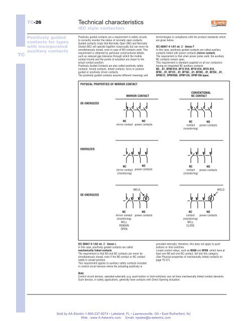
PHYSICAL PROPERTIES OF MIRROR CONTACT<br />
DE-ENERGIZED<br />
MIRROR CONTACT<br />
CONVENTIONAL<br />
NC CONTACT<br />
NC<br />
mirror contact<br />
NO<br />
power contacts<br />
NC NO<br />
contact power contacts<br />
(monitoring)<br />
ENERGIZED<br />
NC<br />
mirror contact<br />
(monitoring)<br />
NO<br />
power contacts<br />
NC NO<br />
contact power contacts<br />
(monitoring)<br />
DE-ENERGIZED<br />
WELD<br />
WELD<br />
NC<br />
mirror contact<br />
(monitoring)<br />
WILL<br />
REMAIN<br />
OPEN<br />
NO<br />
power contacts<br />
NC<br />
contact<br />
(monitoring)<br />
WILL<br />
CLOSE<br />
NO<br />
power contacts<br />
IEC 60947-5-1/A2 ed. 2 - Annex L<br />
In this case, positively guided contacts are called<br />
mechanically linked contacts.<br />
The requirement is that NO and NC contacts can never be<br />
simultaneously closed, even if the NO contact or NC contact<br />
welds in closed position.<br />
This requirement applies to auxiliary safety contacts included<br />
in control circuit devices where the actuating positively is<br />
provided internally; therefore, this does not apply to push<br />
buttons or limit switches.<br />
Lovato control relays, such as BG00 and BF00, which have at<br />
least one NO and one NC contact, fall into this category.<br />
(See Physical properties of mechanically linked contacts on<br />
page TC-27).<br />
Note:<br />
Control circuit devices, operated externally (e.g. push-button or limit-switches) can not have mechanically linked contact elements.<br />
Such devices, in safety applications, generally have contacts with Direct Opening Actuation.<br />
Sold by <strong>AA</strong> <strong>Electric</strong> 1-800-237-8274 • Lakeland, FL • Lawrenceville, GA • East Rutherford, NJ<br />
Web : www.A-Aelectric.com Email: njsales@a-aelectric.com