


You also want an ePaper? Increase the reach of your titles
YUMPU automatically turns print PDFs into web optimized ePapers that Google loves.
<strong>API</strong> <strong>1080</strong> DIN<br />
Installation and Setup<br />
DC Input<br />
ELECTRICAL CONNECTIONS<br />
WARNING! All wiring must be performed by qualified personnel only.<br />
This module requires an industry-standard DIN rail mount. Order <strong>API</strong> TK36 DIN<br />
rail separately.<br />
Power Input Terminals – The label on the side of the <strong>API</strong> module will indicate<br />
the voltage requirements. Power is connected to terminals 10 and 12. Observe<br />
polarity when using DC power. Positive (+) is wired to terminal 12 and negative<br />
(–) is wired to terminal 10. Terminal 11 earth ground may be used if required.<br />
Powered Signal Input – Polarity must be observed when connecting the signal<br />
input. The positive connection (+) is applied to terminal 8 and the negative (–) is<br />
applied to terminal 7.<br />
Using the 12 VDC Power Supply with a Passive Signal Input – This may<br />
save the expense of purchasing a separate power supply for the input device. A<br />
passive input device can be powered by the 12 volt DC power supply at terminal<br />
9. Polarity must be observed when connecting the signal input. Typically the<br />
positive (+) lead is wired to terminal 9 and the negative (–) lead is connected to<br />
terminal 8. A typical example is shown. It is very important to consult the manufacturer<br />
of your specific sensor to determine its compatibility and proper wiring.<br />
Relay Output Terminals – Terminals 1, 2, 3 and 4, 5, 6 provide the appropriate<br />
connections for the desired relay operations. (NC = Normally Closed, C =<br />
Common, NO = Normally Open).<br />
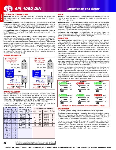
WIRING EXAMPLES<br />
<strong>API</strong> <strong>1080</strong> DIN With<br />
Powered Current or<br />
Voltage Input<br />
NC<br />
COM<br />
NO<br />
Contact Set 1<br />
1 2 3<br />
Contact Set 2 4 5 6<br />
Powered<br />
4-20 mA or (+)<br />
Voltage<br />
Input<br />
Device (–)<br />
7 Input (–)<br />
7 8 9<br />
8 Input (+)<br />
9 no connection<br />
10 11 12<br />
Power AC or DC (–)<br />
Earth Ground<br />
Power AC or DC (+)<br />
<strong>API</strong> <strong>1080</strong> DIN<br />
Using +12V Loop<br />
Power Supply<br />
Contact Set 1<br />
Contact Set 2<br />
Passive (+)<br />
2-Wire<br />
Input<br />
Device (–)<br />
7 no connection<br />
8 Input (–)<br />
9 +12 V Loop<br />
Power AC or DC (–)<br />
Earth Ground<br />
Power AC or DC (+)<br />
NC<br />
COM<br />
NO<br />
1 2 3<br />
4 5 6<br />
7 8 9<br />
10 11 12<br />
RANGE SELECTION<br />
The <strong>API</strong> <strong>1080</strong> DIN input selector switch determines the input impedance for the<br />
module, typically 50 Ω for current inputs and 250 kΩ or greater for voltage<br />
inputs. The switch settings will determine the exact operation of the module.<br />
Following are the standard input range and alarm configuration tables used to<br />
configure the <strong>API</strong> <strong>1080</strong> DIN. Set switches A, B, C and D accordingly.<br />
EXAMPLE: For 4-20 mADC input, HI alarm, non-latching, normal action.<br />
Set switches as follows: A = “I” (current); B = “5”; C = “F”; D = “2”<br />
VOLTAGE Inputs CURRENT Inputs<br />
Set switch A to “V” Set switch A to “I”<br />
ALARM CONFIGURATION<br />
Range<br />
Switches<br />
Range<br />
Switches Type Latch Action<br />
Switch<br />
B C B C D<br />
0-50 mV 8 1 0-1 mA C 1 HI No Normal 2<br />
0-100 mV 9 1 0-2 mA 0 1 HI No Reverse 6<br />
0-200 mV A 1 0-4 mA 1 1 HI Yes Normal 0<br />
0-250 mV C 1 0-8 mA 2 1 HI Yes Reverse 4<br />
0-400 mV B 1 2-10 mA 2 F LO No Normal 3<br />
0-500 mV 0 1 0-10 mA 4 1 LO No Reverse 7<br />
0-1 V 1 1 0-16 mA 3 1 LO Yes Normal 1<br />
0-2 V 2 1 0-20 mA 5 1 LO Yes Reverse 5<br />
0-2.5 V 4 1 4-20 mA 5 F<br />
0-4 V 3 1<br />
1-5 V 5 F<br />
0-5 V 5 1<br />
0-10 V 6 1<br />
±5 V 6 4<br />
±10 V 7 4<br />
SETUP<br />
Setpoint Control – This multi-turn potentiometer allows the operator to adjust<br />
the level at which the alarm is activated. This control is adjustable from 0 to<br />
100% of the input range.<br />
Deadband Control – This potentiometer allows the alarm trip and reset window<br />
to be adjusted symmetrically about the setpoint from 1 to 100% of the span. This<br />
allows the operator to fine tune the point at which the alarm trips and resets. The<br />
deadband is typically used to prevent chattering of the relays or false trips when<br />
the process signal is unstable or changes rapidly.<br />
Test Switch and Test Range – The functional Test pushbutton toggles the<br />
alarm status independent of the input when depressed. It verifies the alarm and<br />
system operation without having to alter the input signal.<br />
OPERATION<br />
GREEN LoopTracker ® Input LED – Provides a visual indication that a signal is<br />
being sensed by the input circuitry of the module. It indicates the input signal<br />
strength by changing in intensity as the process changes from minimum to maximum.<br />
If the LED fails to illuminate, or fails to change in intensity as the process<br />
changes, this may indicate a problem with module power or signal input wiring.<br />
Bi-Color Alarm LED – Provides a visual indication of the alarm status. In all<br />
configurations, a GREEN LED indicates a non-alarm condition and a RED LED<br />
indicates an alarm condition.<br />
Alarm Relays – In the normal mode of operation (failsafe), the relay coil is energized<br />
in a non-alarm condition and de-energized in an alarm condition. This will<br />
create an alarm condition if the module loses power. For a normal acting, nonlatching<br />
configuration, the alarm will activate when the input signal exceeds the<br />
setpoint (HI alarm) or falls below the setpoint (LO alarm), then will automatically<br />
reset when the alarm condition no longer exists.<br />
For a reverse acting alarm (non-failsafe), the relay coil is de-energized in a nonalarm<br />
condition and energized in an alarm condition. The alarm activates when<br />
the input signal exceeds the setpoint (HI alarm) or falls below the setpoint (LO<br />
alarm), then automatically resets when the alarm condition no longer exists.<br />
When the latching mode is selected, it will be necessary to push the functional<br />
test pushbutton or remove power from the module to reset the alarm. The alarm<br />
will only reset if the alarm condition no longer exists.<br />
No Alarms<br />
GREEN Relay 1<br />
1: NC<br />
2: C<br />
3: NO<br />
GREEN Relay 2<br />
4: NC<br />
5: C<br />
6: NO<br />
HI Alarm<br />
RED Relay 1<br />
1: NC<br />
2: C<br />
3: NO<br />
GREEN Relay 2<br />
4: NC<br />
5: C<br />
6: NO<br />
LO Alarm<br />
GREEN Relay 1<br />
1: NC<br />
2: C<br />
3: NO<br />
RED<br />
<strong>API</strong> <strong>1080</strong> DIN Alarm States with Normal Action HI/LO Alarms<br />
Relay 2<br />
4: NC<br />
5: C<br />
6: NO<br />
CALIBRATION<br />
The input ranges are factory calibrated and do not require adjustment.<br />
To calibrate the alarm section, set the deadband control to the minimum. Set the<br />
signal source to a reference that represents the desired trip point. Adjust the setpoint<br />
control to the point at which the relay changes state form a non-alarm to<br />
an alarm condition. The deadband will be 1.0% of span in this case.<br />
If a larger amount of deadband is desired, the deadband control may be<br />
increased by turning the control clockwise. The deadband is symmetrical about<br />
the setpoint; both transition points will change as deadband is increased. In<br />
addition, the test button can be used at any time to toggle the relay state independent<br />
of the input and the output to verify system operation.<br />
32<br />
<strong>API</strong> maintains a constant effort to upgrade and improve its products. Specifications<br />
are subject to change without notice. Consult factory for your specific requirements.<br />
Sold by <strong>AA</strong> <strong>Electric</strong> 1-800-237-8274 Lakeland, FL • Lawrenceville, GA • Greensboro, NC • East Rutherford, NJ www.A-Aelectric.com


