Servo Systems
Servo Systems
Servo Systems

You also want an ePaper? Increase the reach of your titles
YUMPU automatically turns print PDFs into web optimized ePapers that Google loves.
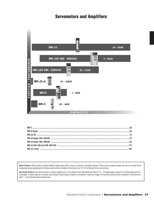
<strong>Servo</strong>motors and Amplifiers<br />
MR-C ............................................................................................................................................................................................58<br />
MR-E Super ................................................................................................................................................................................62<br />
MR-J2-JR ....................................................................................................................................................................................72<br />
MR-J2-Super 200~230VAC ........................................................................................................................................................75<br />
MR-J2-Super 380~480VAC ........................................................................................................................................................94<br />
MR-J3 200~230 and 380~480 VAC ..........................................................................................................................................113<br />
MR-J3 Linear ............................................................................................................................................................................165<br />
Stock Product: Stock product is product MEAU makes every effort to have on hand for immediate shipment. There may be instances when we are out of stock due to<br />
unexpected large requirements. All stock product will be indicated in this book by an “S” in the Stocked Item columns/rows.<br />
Non-Stock Product: Non-stock product is product supplied on an “as-needed” basis. Standard lead times of 12 – 16 weeks apply, product is non-returnable and noncancelable.<br />
Product listed as non-stock may change to stock product subject to increases in sales and usage. All non-stock product will be indicated in this book by a<br />
dash “–” in the Stocked Item columns/rows.<br />
Mitsubishi Electric Automation | <strong>Servo</strong>motors and Amplifiers 57
SERVOMOTORS AND AMPLIFIERS<br />
MR-C <strong>Servo</strong>motors and Amplifiers<br />
The ideal alternative to micro-stepper and 5-phase stepper motors with: patented Real-Time Adaptive Tuning; RS-232C<br />
serial interface for Windows ® based set-up (MR-Configurator); and three standard pulse input formats.<br />
A<br />
B<br />
If motor has brake, connect<br />
to customer’s Brake Control<br />
Circuit.<br />
C<br />
D<br />
E<br />
F<br />
A. Motor ..........................................................................................................................................................................59<br />
B. Amplifier ......................................................................................................................................................................59<br />
C. Encoder Cable ............................................................................................................................................................59<br />
D. Terminal Block Cable ..................................................................................................................................................59<br />
E. Terminal Block ............................................................................................................................................................59<br />
F. Optional Accessories ..................................................................................................................................................59<br />
58
A<br />
C<br />
B<br />
D<br />
E<br />
Rated<br />
Torque<br />
oz-in<br />
Power<br />
kW<br />
Inertia<br />
oz-in 2<br />
13.5 0.03 0.077<br />
22.7 0.05 0.104<br />
45.3 0.1 0.164<br />
90.7 0.2 0.487<br />
A<br />
Motor Model No.<br />
(*1, *2, *3)<br />
Stocked<br />
Item<br />
HC-PQ033-UE –<br />
HC-PQ033N-UE –<br />
HC-PQ053-UE –<br />
HC-PQ053N-UE –<br />
HC-PQ13-UE<br />
HC-PQ13N-UE<br />
S<br />
S<br />
Encoder<br />
Cable<br />
Length<br />
2m<br />
5m<br />
10m<br />
HC-PQ23K-UE S 2m<br />
5m<br />
HC-PQ23NK-UE S 10m<br />
C<br />
Encoder Model<br />
No. (*4)<br />
MR-JCCBL2M-L<br />
MR-JCCBL5M-L<br />
MR-JCCBL10M-L<br />
MR-JCCBL2M-L<br />
MR-JCCBL5M-L<br />
MR-JCCBL10M-L<br />
Stocked<br />
Item<br />
Input<br />
Voltage<br />
VAC, Ph<br />
Command<br />
Pulse<br />
Voltage<br />
HC-PQ 3000 RPM <strong>Servo</strong>motors<br />
S<br />
S<br />
S<br />
S<br />
S<br />
S<br />
110, 1<br />
110, 1<br />
230, 1<br />
230, 1<br />
110, 1<br />
110, 1<br />
230, 1<br />
230, 1<br />
5VDC<br />
24VDC<br />
5VDC<br />
24VDC<br />
5VDC<br />
24VDC<br />
5VDC<br />
24VDC<br />
B D E<br />
Terminal<br />
Terminal<br />
Amplifier Model Stocked Block Cable Stocked<br />
Stocked<br />
No. (*5) Item Model No.<br />
Block<br />
Item<br />
Item<br />
(0.5, 1m)<br />
Model No.<br />
MR-C10A1-L-UE<br />
MR-C10A1-UE<br />
MR-C10A-L-UE<br />
MR-C10A-UE<br />
MR-C20A1-L-UE<br />
MR-C20A1-UE<br />
MR-C20A-L-UE<br />
MR-C20A-UE<br />
S<br />
S<br />
–<br />
–<br />
S<br />
S<br />
–<br />
S<br />
MR-CTBL05M S MR-TB20 S<br />
MR-CTBL05M S MR-TB20 S<br />
184 0.4 0.793<br />
HC-PQ43K-UE S 2m<br />
5m<br />
HC-PQ43NK-UE S 10m<br />
MR-JCCBL2M-L<br />
MR-JCCBL5M-L<br />
MR-JCCBL10M-L<br />
S<br />
S<br />
S<br />
230, 1<br />
230, 1<br />
5VDC<br />
24VDC<br />
MR-C40A-L-UE<br />
MR-C40A-UE<br />
S<br />
S<br />
MR-CTBL05M S MR-TB20 S<br />
HC-PQ 3000 RPM <strong>Servo</strong>motors with Brake<br />
13.5 0.03 0.094<br />
22.7 0.05 0.117<br />
45.3 0.1 0.176<br />
HC-PQ033B-UE –<br />
HC-PQ033NB-UE –<br />
HC-PQ053B-UE –<br />
HC-PQ053NB-UE –<br />
HC-PQ13B-UE –<br />
HC-PQ13NB-UE –<br />
2m<br />
5m<br />
10m<br />
MR-JCCBL2M-L<br />
MR-JCCBL5M-L<br />
MR-JCCBL10M-L<br />
S<br />
S<br />
S<br />
110, 1<br />
110, 1<br />
230, 1<br />
230, 1<br />
5VDC<br />
24VDC<br />
5VDC<br />
24VDC<br />
MR-C10A1-L-UE<br />
MR-C10A1-UE<br />
MR-C10A-L-UE<br />
MR-C10A-UE<br />
S<br />
S<br />
–<br />
–<br />
MR-CTBL05M S MR-TB20 S<br />
90.7 0.2 0.790<br />
HC-PQ23BK-UE –<br />
HC-PQ23NBK-UE –<br />
2m<br />
5m<br />
10m<br />
MR-JCCBL2M-L<br />
MR-JCCBL5M-L<br />
MR-JCCBL10M-L<br />
S<br />
S<br />
S<br />
110, 1<br />
110, 1<br />
230, 1<br />
230, 1<br />
5VDC<br />
24VDC<br />
5VDC<br />
24VDC<br />
MR-C20A1-L-UE<br />
MR-C20A1-UE<br />
MR-C20A-L-UE<br />
MR-C20A-UE<br />
S<br />
S<br />
–<br />
S<br />
MR-CTBL05M S MR-TB20 S<br />
184 0.4 1.04<br />
HC-PQ43BK-UE – 2m<br />
5m<br />
HC-PQ43BK-UE – 10m<br />
MR-JCCBL2M-L<br />
MR-JCCBL5M-L<br />
MR-JCCBL10M-L<br />
S<br />
S<br />
S<br />
230, 1<br />
230, 1<br />
5VDC<br />
24VDC<br />
MR-C40A-L-UE<br />
MR-C40A-UE<br />
S<br />
S<br />
MR-CTBL05M S MR-TB20 S<br />
Notes:<br />
1. Keyways with keys are only available and are STANDARD on 200W and 400W motors.<br />
2. “N” indicates NEMA sized mounting adapter: 30 to 100 W are NEMA 23; 200 & 400 W are NEMA 34. (MOTOR SHAFT MAY NOT BE NEMA SIZE.) See manual for details.<br />
3. Power to motor from amplifier must be provided by separate wires. Motor has pigtails (0.3m) with ring type connectors for power and optional brake connections.<br />
Motors with brakes require separate 24VDC power supply.<br />
4. MR-JCCBLM cable is rated IP20. No higher IP-rated cable is currently available.<br />
5. The MR-C40A is not available in 110 VAC, 1 phase version.<br />
Torque (oz.in)<br />
60<br />
54<br />
50<br />
40<br />
30<br />
20<br />
13.5<br />
10<br />
Torque (N•m)<br />
0.4<br />
0.3<br />
0.2<br />
0.1<br />
0 0<br />
HC-PQ033 (B)<br />
Intermittent operating range<br />
Continuous operating range<br />
1500 3000 4500<br />
Rotation speed (rpm)<br />
Torque (oz.in)<br />
100<br />
90.6<br />
80<br />
60<br />
40<br />
22.7<br />
20<br />
0<br />
Torque (N•m)<br />
0.8<br />
0.6<br />
0.4<br />
0.2<br />
0<br />
HC-PQ053 (B)<br />
220<br />
181.2<br />
180<br />
Intermittent operating range<br />
Torque (oz.in)<br />
120<br />
80<br />
45.3<br />
40<br />
Continuous operating range<br />
0<br />
1500 3000 4500<br />
Rotation speed (rpm)<br />
Torque (N•m)<br />
1.5<br />
1.2<br />
0.9<br />
0.6<br />
0.3<br />
0<br />
HC-PQ13 (B)<br />
Intermittent operating range<br />
Continuous operating range<br />
1500 3000 4500<br />
Rotation speed (rpm)<br />
Optional Accessories F<br />
6.<br />
Encoder Connector Kit<br />
(instead of MR-JCCBL■M-L)<br />
Model Number<br />
MR-J2CNM<br />
7. CN1 I/O Connector Kit MR-J2CN1 S<br />
8. CN1 I/O Pigtail Cable<br />
MR-CCN1CBL-3M (3 meter)<br />
MR-CCN1CBL-5M (5 meter)<br />
Stk<br />
Item<br />
S<br />
S<br />
Torque (oz.in)<br />
300<br />
272<br />
250<br />
200<br />
150<br />
100<br />
90.7<br />
50<br />
0<br />
Torque (N•m)<br />
2.0<br />
1.5<br />
1.0<br />
0.5<br />
0<br />
HC-PQ23 (B)<br />
Intermittent interval<br />
operating range<br />
Continuous operating range<br />
1500 3000 4500<br />
Rotation speed (rpm)<br />
Torque (oz.in)<br />
600<br />
500<br />
414<br />
400<br />
300<br />
200<br />
184<br />
100<br />
0<br />
Torque (N•m)<br />
4.0<br />
3.0<br />
2.0<br />
1.0<br />
0<br />
HC-PQ43 (B)<br />
Intermittent interval<br />
operating range<br />
Continuous operating range<br />
1500 3000 4500<br />
Rotation speed (rpm)<br />
9. Serial Interface (RS-232C) Adaptor MR-C-T01 –<br />
10.<br />
11.<br />
Serial Interface Cable (for use with<br />
“MR-CONFIGURATOR” and customer’s<br />
PC)<br />
Windows Communication Software<br />
“MR-CONFIGURATOR”<br />
MR-CPCATCBL3M<br />
(3 meter)<br />
MR-CONFIGURATOR<br />
12a. MR-C Instruction Manual SH(NA)3167 –<br />
S<br />
S<br />
12b. MR-C Installation Manual IB(NA)67279 –<br />
12c. EMC Installation Guide IB(NA)67310 –<br />
Note: Many of these manuals are available for free download from our website, www.meau.com<br />
Mitsubishi Electric Automation | <strong>Servo</strong>motors and Amplifiers 59
SERVOMOTORS AND AMPLIFIERS<br />
A<br />
MR-C Motor Specifications<br />
<strong>Servo</strong>motor<br />
HC-PQ Series<br />
Item 033 053 13 23 43<br />
Corresponding <strong>Servo</strong> Amplifier Model MR-C10A (1) MR-C20A (1) MR-C40A<br />
Rated Output (W) 30 50 100 200 400<br />
Continuous (N • m) 0.095 0.16 0.32 0.64 1.27<br />
Characteristic Rated Torque (kgf • cm) 0.97 1.62 3.25 6.5 13.0<br />
(*2) (*6) (oz • in) 13.45 22.66 45.32 90.63 184.1<br />
(N • m) 0.38 0.64 1.28 1.92 2.92<br />
Max. Torque (*2)<br />
(kgf • cm) 3.88 6.48 13 19.5 29.9<br />
(oz • in) 53.81 90.63 181.26 271.89 414<br />
Rated Speed (r/min) 3000<br />
Max. Speed (r/min) 4500<br />
Instantaneous Permissible Speed (r/min) 5400 5175<br />
Power Rate at Continuous Rated Torque (kW/s) 6.45 13.47 34.13 46.02 116.55<br />
J (kg • cm 2 ) 0.014 0.019 0.03 0.089 0.145<br />
Moment of<br />
GD 2 (kgf • cm 2 ) 0.057 0.074 0.12 0.35 0.57<br />
Inertia (*7)<br />
WK 2 (oz • in 2 ) 0.077 0.104 0.164 0.487 0.793<br />
Recommended Load Inertia to <strong>Servo</strong>motor Shaft Inertia 30 or less times (*5)<br />
Rated Output Current (A) 0.85 0.85 0.85 1.5 2.8<br />
Max. Output Current (A) 5.0 5.0 5.0 6.0 6.44<br />
Regenerative Without Option (*4-1) (*4-1) (*4-2) (*4-3) (*4-4)<br />
Brake Duty MR-RB013 (10W) (*4-1) (*4-1) 4660 1400 800<br />
(Times / Min) (*4) MR-RB033 (30W) (*4-1) (*4-1) (*4-1) 4300 2400<br />
Power Facility Capacity (kVA) 0.1 0.2 0.3 0.5 0.9<br />
Speed/Position Detector<br />
Encoder (resolution 4000 (Pulse/rev))<br />
Accessories<br />
Encoder (serial communication system)<br />
Structure Totally enclosed, natural air cooling (protection degree: IP44 (*8))<br />
Environmental Condition (*1)<br />
Refer to User Manual<br />
Weight (*7)<br />
kg 0.32 0.37 0.50 0.96 1.42<br />
lbs 0.71 0.82 1.1 2.12 3.13<br />
Notes:<br />
1. Special specifications are required for servomotor used in a site exposed to oil or rain.<br />
2. The output torque and rated speed are not guaranteed during a power voltage drop.<br />
3. The power facility capacity will differ according to the impedance.<br />
4. The regenerative brake duty is the permissible duty applied when the servomotor under no load is decelerated to a stop from the rated speed. For those marked D, there are no limits to the regenerative<br />
duty if the effective torque is not more than the rated torque. When a load is applied, the value is 1/(m+1) of the value in the table. (m=load inertia/motor inertia). If the speed exceeds the rated speed, the<br />
permissible number of times is in inverse proportion to the square of (running speed / rated speed). When the running speed frequently varies or when the regeneration state is constantly established as in<br />
vertical motion applications, calculate the amount of regenerative heat generated during the operation so that the amount of heat generated will not be larger than the permissible value.<br />
4-1. There are no limits to the regenerative duty if the effective torque is not more than the rated torque.<br />
4-2. When the load inertia is 30 times or less, there is no limit to the regenerative brake duty, if the effective torque is not more than the rated torque.<br />
4-3. When the load inertia is 10 times or less, there is no limit to the regenerative brake duty, if the effective torque is not more than the rated torque.<br />
4-4. When the load inertia is 1 time or less, there is no limit to the regenerative brake duty, if the effective torque is not more than the rated torque.<br />
5. Please consult Mitsubishi when the load inertia ratio exceeds the value noted above.<br />
6. For servomotors with reduction gear, the ratio is 300% of the rated torque on the servomotor shaft.<br />
7. For servomotors with reduction gear and electromagnetic brake, refer to the outline drawings.<br />
8. Except the shaft and connector.<br />
B<br />
Item<br />
MR-C Amplifier Specifications<br />
<strong>Servo</strong> Amplifier MR-C10A MR-C20A MR-C40A MR-C10A1 MR-C20A1<br />
Voltage / Frequency Single-phase 200 to 230VAC 50/60 Hz Single-phase 100 to 120VAC 50/60 Hz<br />
Power Supply<br />
Permissible Voltage Fluctuation Single-phase 170VAC to 253 VAC Single-phase 85 to 126VAC<br />
(*3)<br />
Permissible Frequency Fluctuation Within ± 5%<br />
Control Method<br />
Sine-wave PWM control, current controlled system<br />
Control Mode<br />
Pulse train input position control<br />
Control Theory<br />
Model adaptive control<br />
Auto Tuning<br />
Real-time auto tuning<br />
Over current protection, motor combination fault, overload shut off (electronic thermal relay)<br />
Protective Functions<br />
over voltage protection, encoder alarm protection, regenerative alarm protection, under voltage/<br />
instantaneous power failure protection, over speed protection, excessive error protection<br />
Max. Input Pulse Frequency<br />
200kpps<br />
Position Control<br />
Positioning Feedback Pulses<br />
4000 pulse/rev servomotor revolution<br />
Specifications<br />
Command Pulse Multiplication Electronic gear A, B: 1 to 999 pulses 1/50 < A/B
MR-C Shaft Dimensions<br />
With Key<br />
L Cut<br />
<strong>Servo</strong> Motor<br />
Model<br />
Shaft Shape<br />
With Key D Cut L Cut<br />
HC-PQ033 — X —<br />
HC-PQ053 — X —<br />
HC-PQ13 — X —<br />
HC-PQ23 X X X<br />
HC-PQ43 X X<br />
D Cut<br />
<strong>Servo</strong> Motor<br />
Model<br />
HC-PQ033<br />
HC-PQ053<br />
HC-PQ13<br />
HC-PQ23<br />
HC-PQ43<br />
Variable Dimensions<br />
R QK S<br />
25 (0.98) 20.5 (0.81) 8 (0.31)<br />
30 (1.18) 25.5 (1) 14 (0.55)<br />
Mitsubishi Electric Automation | <strong>Servo</strong>motors and Amplifiers 61
SERVOMOTORS AND AMPLIFIERS<br />
MR-E Super <strong>Servo</strong>motors and Amplifiers<br />
High performance and compact, the MR-E Super is an excellent choice for applications up to 2kW. The MR-E Super is<br />
available in pulse-train position or analog speed/torque models. The amplifier features Mitsubishi Electric’s legendary autotuning<br />
and vibration suppression functions, a 400 Hz analog frequency response, and accepts pulse commands up to 500<br />
kHz. The motors are low to medium inertia up to 4500 rpm and are equipped with a 131,072 pulse per revolution encoder.<br />
Set-up and diagnosis is made easy with the MR-Configurator Windows ® based software.<br />
A<br />
D<br />
A<br />
D<br />
E<br />
C<br />
C<br />
E<br />
C<br />
(Order separately)<br />
B<br />
C<br />
(Order separately)<br />
B<br />
A. Amplifier ....................................................................................................................................................................63<br />
B. Motor..........................................................................................................................................................................64<br />
C. Cables / Connectors ..................................................................................................................................................67<br />
D. Software and Manuals ..............................................................................................................................................70<br />
E. Optional Accessories ................................................................................................................................................70<br />
62
A<br />
MR-E Super Amplifiers<br />
Amplifier Selection<br />
MR-E-■ ■ -KH003<br />
Super Series<br />
Mitsubishi E-Series<br />
general purpose AC<br />
<strong>Servo</strong> Amplifier<br />
Conforms to<br />
the following<br />
standards: EN,<br />
UL, cUL<br />
Symbol<br />
A<br />
AG<br />
Symbol<br />
Compatible Motor<br />
HF-KE■ W1-S100 HF-SE■ JW1-S100<br />
10 13 —<br />
20 23 —<br />
40 43 —<br />
70 73 52<br />
100 — 102<br />
200 —- 152, 202<br />
Description<br />
General Pulse Train Interface<br />
Analog Input Interface<br />
Stocked Amplifiers<br />
Model Number<br />
MR-E-10A-KH003<br />
MR-E-10AG-KH003<br />
MR-E-20A-KH003<br />
MR-E-20AG-KH003<br />
MR-E-40A-KH003<br />
MR-E-40AG-KH003<br />
MR-E-70A-KH003<br />
MR-E-70AG-KH003<br />
MR-E-100A-KH003<br />
MR-E-100AG-KH003<br />
MR-E-200A-KH003<br />
MR-E-200AG-KH003<br />
<strong>Servo</strong> Standard Specifications<br />
<strong>Servo</strong> Amplifier MR-E-10A-KH003 MR-E-20A-KH003 MR-E-40A-KH003 MR-E-70A-KH003 MR-E-100A-KH003 MR-E-200A-KH003<br />
<strong>Servo</strong> Amplifier with Analog Input Interface MR-E-10AG-KH003 MR-E-20AG-KH003 MR-E-40AG-KH003 MR-E-70AG-KH003 MR-E-100AG-KH003 MR-E-200AG-KH003<br />
Power<br />
Supply<br />
System<br />
Dynamic Brake<br />
Voltage / Frequency 3-phase 200 to 230VAC, 50/60Hz or 1-phase 230VAC, 50/60Hz 3-phase 200 to 230VAC, 50/60Hz<br />
Permissible Voltage Fluctuation 3-phase 200 to 230VAC: 170 to 253VAC 1-phase 230 VAC: 207 to 253VAC 3-phase 170 to 253VAC<br />
Permissible Frequency Fluctuation Within ±5%<br />
Sine-wave PWM control, current control system<br />
Built-in<br />
Protective Functions<br />
A Type Amps<br />
AG Type Amps<br />
Structure<br />
Environment<br />
Position<br />
Control<br />
Mode<br />
Internal<br />
Speed<br />
Control<br />
Mode<br />
Speed<br />
Control<br />
Mode<br />
Torque<br />
Control<br />
Mode<br />
Overcurrent shut-off, regenerative overvoltage shut-off, overload shut-off (electronic thermal relay), encoder error protection,<br />
regenerative brake error protection, undervoltage, instantaneous power failure protection, overspeed protection,<br />
excessive error protection<br />
Max. Input Pulse Frequency<br />
1 Mpps (for differential receiver), 200kpps (for open collector)<br />
Command Pulse Multiplying Factor Electronic gear A:1 to 65535 B:1 to 65535, 1/50 < A/B < 50<br />
In-Position Range Setting<br />
0 to ± 16384 pulse (command pulse unit)<br />
Error Excessive<br />
±2.5 revolutions<br />
Torque Limit<br />
Set by parameter setting<br />
Speed Control Range Internal speed command 1: 5000<br />
Speed Fluctuation Ratio ±0.01% or less (load fluctuation 0 to 100%); 0% or less (power fluctuation ±10%)<br />
Torque Limit<br />
Set by parameter setting<br />
Speed Control Range Analog speed command 1: 2000, internal speed command 1: 5000<br />
Analog Speed Command Input<br />
0 to ± 10VDC / Rated speed<br />
Speed Fluctuation Ratio<br />
±0.01% or less (load fluctuation 0 to 100%); 0% or less (power fluctuation ±10%)<br />
±0.2% max. (ambient temperature 25 ±10°C) for external speed setting only<br />
Torque Limit<br />
Set by parameter setting or external analog input (0 to +10VDC / maximum torque)<br />
Analog Torque Command Input<br />
0 to ±8VDC / Maximum torque (input impedance 10 to 12kΩ)<br />
Speed Limit<br />
Set by parameter setting or external analog input (0 to ±10 / Rated speed)<br />
Self-cooled, open (IP00)<br />
Force-cooling,<br />
open (IP00)<br />
Ambient Operation °C (°F)<br />
0 to +55 (non-freezing) (32 to +131 (non-freezing))<br />
Temperature Storage °C (°F)<br />
-20 to +65 (non-freezing) (-4 to +149 (non-freezing))<br />
Ambient Operation<br />
Humidity Storage<br />
90%RH or less (non-condensing)<br />
Ambient<br />
Indoors (no direct sunlight) Free from corrosive gas, flammable gas, oil mist, dust and dirt<br />
Altitude<br />
Max. 1000m (3280 ft) above sea level<br />
Vibration<br />
5.9 [m/s 2 ] or less; 19.4 [ft/s 2 ] or less<br />
Weight kg (lb) 0.7 (1.5) 0.7 (1.5) 1.1 (2.4) 1.7 (3.7) 1.7 (3.7) 2.0 (4.4)<br />
Mitsubishi Electric Automation | <strong>Servo</strong>motors and Amplifiers 63
SERVOMOTORS AND AMPLIFIERS<br />
B<br />
MR-E Super <strong>Servo</strong>motors<br />
<strong>Servo</strong>motor Selection<br />
HF-KE 3 W1-S100<br />
Rated Speed<br />
3000 (r/min)<br />
Symbol<br />
None<br />
K<br />
Super Series<br />
Encoder Resolution 131,072 ppr (Inc)<br />
Shaft Shape<br />
Standard<br />
(Straight Shaft)<br />
With Keyway (Note)<br />
Note: Keyway only on 200W ~ 700W with key included.<br />
Symbol<br />
None<br />
B<br />
Electromagnetic Brake<br />
Without Brake<br />
With Brake<br />
Stocked Motors<br />
Model Number<br />
HF-KE13W1-S100<br />
HF-KE13BW1-S100<br />
HF-KE23KW1-S100<br />
HF-KE23BKW1-S100<br />
HF-KE43KW1-S100<br />
HF-KE43BKW1-S100<br />
HF-KE73KW1-S100<br />
HF-KE73BKW1-S100<br />
Symbol Rated Output (W)<br />
1 100<br />
2 200<br />
4 400<br />
7 750<br />
HF-SE 2 J W1-S100<br />
With Oil Seal<br />
Rated Speed<br />
2000 (r/min)<br />
Symbol Rated Output (W)<br />
5 500<br />
10 1000<br />
15 1500<br />
20 2000<br />
Symbol<br />
None<br />
K<br />
Note: Key not included.<br />
Symbol<br />
None<br />
B<br />
Super Series<br />
Encoder Resolution 131,072 ppr (Inc)<br />
Shaft Shape<br />
Standard<br />
(Straight Shaft)<br />
With Keyway (Note)<br />
Electromagnetic Brake<br />
Without Brake<br />
With Brake<br />
Stocked Motors<br />
Model Number<br />
HF-SE52JKW1-S100<br />
HF-SE52BJKW1-S100<br />
HF-SE102JKW1-S100<br />
HF-SE102BJKW1-S100<br />
HF-SE152JKW1-S100<br />
HF-SE152BJKW1-S100<br />
HF-SE202JKW1-S100<br />
HF-SE202BJKW1-S100<br />
Motor Series<br />
Rated Speed<br />
(Max. r/min)<br />
Rated Output<br />
Capacity (kW)<br />
<strong>Servo</strong>motor<br />
Brake (B)<br />
EN<br />
UL<br />
cUL<br />
Protective Rating<br />
Features<br />
Application<br />
Examples<br />
Small Capacity<br />
Medium Capacity<br />
HF-KE Super Series<br />
HF-SE Super Series<br />
3000<br />
(4500)<br />
2000<br />
(3000)<br />
4 Types<br />
0.1, 0.2, 0.4, 0.75 Yes Yes Yes<br />
4 Types<br />
0.5, 1.0, 1.5, 2.0 Yes Yes Yes<br />
IP55<br />
Excluding the shaftthrough<br />
portion and<br />
connector<br />
IP55<br />
Excluding the shaftthrough<br />
portion<br />
Stable control from<br />
low speeds to high<br />
speeds allows<br />
compliance with<br />
a variety of<br />
applications.<br />
Belt Drive<br />
Robots<br />
Mounters<br />
Sewing Machines<br />
X-Y Tables<br />
Food Processing<br />
Machines<br />
Conveyor Machines<br />
Robots<br />
X-Y Tables<br />
64
MR-E HF-KE Super 3000 Series <strong>Servo</strong>motor Specifications<br />
<strong>Servo</strong>motor Model HF-KE13W1-S100 HF-KE23W1-S100 HF-KE43W1-S100 HF-KE73W1-S100<br />
<strong>Servo</strong>motor Model with Brake HF-KE13BW1-S100 HF-KE23BW1-S100 HF-KE43BW1-S100 HF-KE73BW1-S100<br />
<strong>Servo</strong> Amplifier Model MR-E-10A-KH003 MR-E-20A-KH003 MR-E-40A-KH003 MR-E-70A-KH003<br />
<strong>Servo</strong> Amplifier Model with Analog Input Interface MR-E-10AG-KH003 MR-E-20AG-KH003 MR-E-40AG-KH003 MR-E-70AG-KH003<br />
Power Facility Capacity (kVA) 0.3 0.5 0.9 1.3<br />
Rated Output (W) 100 200 400 750<br />
Continuous<br />
Running Duty (*1) Rated Torque (N·m [oz·in]) 0.32 (45.3) 0.64 (90.6) 1.3 (184) 2.4 (340)<br />
<strong>Servo</strong>motor<br />
Maximum Torque (N·m [oz·in]) 0.95 (135) 1.9 (269) 3.8 (538) 7.2 (1020)<br />
Rated Speed (r/min) 3000<br />
Maximum Speed (r/min) 4500<br />
Permissible Instantaneous Speed (r/min) 5175<br />
Power Rate at Continuous Rated Torque (kW/s) 11.5 16.9 38.6 39.9<br />
Rated Current (A) 0.8 1.4 2.7 5.2<br />
Maximum Current (A) 2.4 4.2 8.1 15.6<br />
Regenerative<br />
Breaking Frequency<br />
(Times/ Min)<br />
Moment of Inertia<br />
J (x10 -4 kg•m 2 )<br />
[J (oz·in 2 )]<br />
With No Options (*3) (*3) 249 140<br />
MR-RB032 (30W) (*3) (*3) 747 210<br />
MR-RB12 (100W) — (*3) 2490 700<br />
MR-RB32 (300W) — — — 2100<br />
Standard 0.088 (0.481) 0.24 (1.31) 0.42 (2.30) 1.43 (7.82)<br />
With Electromagnetic Brake 0.090 (0.492) 0.31 (1.69) 0.50 (2.73) 1.63 (8.91)<br />
Recommended Load/Motor Inertia Moment Rate 15 times the servo motor’s inertia moment maximum (*2)<br />
Speed/Position Detector<br />
Incremental encoder (resolution per servo motor rotation: 131,072 p/rev)<br />
Attachments —<br />
Structure Totally enclosed non ventilated (protection level: IP55) (*4)<br />
Environment (*5)<br />
Ambient Temperature<br />
Ambient Humidity<br />
Atmosphere<br />
0 to 40°C (32 to 104°F) (non-freezing), storage: -15 to 70°C (5 to 158°F) (non-freezing)<br />
80% RH maximum (non-condensing), storage: 90% RH maximum (non-condensing)<br />
Indoors (no direct sunlight); no corrosive gas, inflammable gas, oil mist or dust<br />
Mass kg (lb)<br />
Elevation/Vibration (*6) 1000m or less above sea level; X: 49m/s 2 Y: 49m/s 2<br />
Standard 0.56 (1.3) 0.94 (2.1) 1.5 (3.3) 2.9 (6.4)<br />
With Electromagnetic Brake 0.86 (1.9) 1.6 (3.6) 2.1 (4.7) 3.9 (8.6)<br />
Notes:<br />
1. The rated output and rated speed of the servo motor assume that the rated power supply voltage and frequency are as indicated in Section 1.3 of the MR-E instruction manual.<br />
2. If the load inertia moment ratio exceeds the indicated value, please consult MEAU.<br />
3. When the effective torque is within the rated torque range, there are no restrictions on the regenerative brake duty. Note that the recommended load inertia moment ratio is 15 times or less.<br />
4. Except for the shaft-through portion.<br />
5. In the environment where the servo motor is exposed to oil mist, oil and/or water, the servo motor of the standard specifications may not be usable. Contact MEAU.<br />
6. The vibration direction is shown on the diagram below. The numeric value indicates the maximum value of the component (commonly the bracket is in the opposite direction of the motor shaft).<br />
When the servo motor stops, fretting is likely to occur at the bearing.Therefore, suppress the vibration to about half of the permissible value.<br />
X<br />
Y<br />
Mitsubishi Electric Automation | <strong>Servo</strong>motors and Amplifiers 65
SERVOMOTORS AND AMPLIFIERS<br />
MR-E HF-SE Super 2000 r/min Series <strong>Servo</strong>motor Specifications<br />
<strong>Servo</strong>motor Model HF-SE52JW1-S100 HF-SE102JW1-S100 HF-SE152JW1-S100 HF-SE202JW1-S100<br />
<strong>Servo</strong>motor Model with Brake HF-SE52BJW1-S100 HF-SE102BJW1-S100 HF-SE152BJW1-S100 HF-SE202BJW1-S100<br />
<strong>Servo</strong> Amplifier Model MR-E-70A-KH003 MR-E-100A-KH003 MR-E-200A-KH003<br />
<strong>Servo</strong> Amplifier Model with Analog Input Interface MR-E-70AG-KH003 MR-E-100AG-KH003 MR-E-200AG-KH003<br />
<strong>Servo</strong>motor<br />
Power Facility Capacity (kVA) 1.0 1.7 2.5 3.5<br />
Continuous Running Rated Output (kW) 0.5 1.0 1.5 2.0<br />
Duty (*1)<br />
Rated Torque (N·m [oz·in]) 2.39 (338) 4.77 (675) 7.16 (1010) 9.55 (1350)<br />
Maximum Torque (N·m [oz·in]) 7.16 (1010) 14.3 (2020) 21.5 (3040) 28.6 (4050)<br />
Rated Speed (r/min) 2000<br />
Maximum Speed (r/min) 3000<br />
Permissible Instantaneous Speed (r/min) 3450<br />
Power Rate at Continuous Rated Torque (kW/s) 9.34 19.2 28.8 23.8<br />
Rated Current (A) 2.9 5.3 8.0 10<br />
Maximum Current (A) 8.7 15.9 24 30<br />
Regenerative<br />
Braking Frequency<br />
(Times/Min) (*3, 4)<br />
Moment of Inertia<br />
J (x10 -4 kg·m 2 )<br />
[J (oz·in 2 )]<br />
With No Options 120 62 152 71<br />
MR-RB032 (30W) 180 93 — —<br />
MR-RB12 (100W) 600 310 — —<br />
MR-RB30 (300W) — — 456 213<br />
MR-RB32 (300W) 1800 930 — —<br />
MR-RB50 (500W) — — 760 355<br />
Standard 6.1 (33.4) 11.9 (65.1) 17.8 (97.3) 38.3 (209)<br />
With Electromagnetic Brake 8.3 (45.4) 14.0 (76.5) 20.0 (109) 47.9 (262)<br />
Recommended Load/Motor Inertia Moment Ratio 15 times the servo motor’s inertia moment maximum (*2)<br />
Speed/Position Detector<br />
Incremental encoder (resolution per servo motor: 131,072 p/rev)<br />
Attachments —<br />
Structure<br />
Environment (*3)<br />
Mass (kg [lb])<br />
Ambient Temperature<br />
Ambient Humidity<br />
Atmosphere<br />
Elevation<br />
Totally enclosed non ventilated (protection level: IP55)<br />
0 to 40°C (32 to 104°F) (non-freezing), storage: -15 to 70°C (5 to 158°F) (non-freezing)<br />
80% RH maximum (non-condensing), storage: 90% RH maximum (non-condensing)<br />
Indoors (no direct sunlight); no corrosive gas, inflammable gas, oil mist or dust<br />
1000m or less above sea level<br />
Vibration (*4) X, Y : 24.5m/s 2 X : 24.5m/s 2<br />
Y : 49m/s 2<br />
Standard 4.8 (11) 6.5 (15) 8.3 (19) 12 (27)<br />
With Electromagnetic Brake 6.7 (15) 8.5 (19) 11 (25) 18 (40)<br />
Notes:<br />
1. The rated output and rated speed of the servo motor assume that the rated power supply voltage and frequency are as indicated in Section 1.3 of the MR-E Manual.<br />
2. If the load inertia moment ratio exceeds the indicated value, please consult MEAU.<br />
3. In the environment where the servo motor is exposed to oil mist, oil and/or water, the servo motor of the standard specifications may not be useable. Contact MEAU.<br />
4. The vibration direction is shown on the diagram below. The numeric value indicates the maximum value of the component (commonly the bracket is in the opposite direction of the motor shaft).<br />
When the servo motor stops, fretting is likely to occur at the bearing.Therefore, suppress the vibration to about half of the permissible value.<br />
X<br />
Y<br />
66
C<br />
Cables and Connectors<br />
22<br />
24<br />
25<br />
23<br />
27 28<br />
26<br />
24<br />
11<br />
12<br />
17<br />
18<br />
29 30<br />
3<br />
4<br />
22<br />
24<br />
25<br />
23<br />
27 28<br />
26<br />
24<br />
13<br />
29 30<br />
14<br />
19<br />
20<br />
5 7 7<br />
6<br />
8<br />
8<br />
22<br />
24<br />
25<br />
23<br />
27 28<br />
26<br />
24<br />
1 15<br />
2<br />
21<br />
16<br />
29 30<br />
9<br />
10<br />
31<br />
Mitsubishi Electric Automation | <strong>Servo</strong>motors and Amplifiers 67
SERVOMOTORS AND AMPLIFIERS<br />
MR-E Super Cables and Connectors (refer to chart on previous page)<br />
Item<br />
Power Cables<br />
HF-SE■ (B)JW1-S100<br />
Brake Cables<br />
HF-SE■ BJW1-S100<br />
Encoder Cable for CN2 Connector<br />
HF-KE■ (B)W1-S100<br />
1<br />
2<br />
3<br />
4<br />
5<br />
6<br />
7<br />
Standard-Flex,<br />
Unshielded Type<br />
Cables<br />
(Straight Type<br />
Connector Only)<br />
High-Flex,<br />
Shielded Type<br />
Cables<br />
(Straight type<br />
connector only)<br />
Cable Number<br />
( ■ = cable length 2, 5, 10, 15, 20, 25, 30 meter)<br />
HF-SE52(B)JW1-S100 (*1) MR-J3P1-■ M (*2)<br />
HF-SE102(B)JW1-S100 (*1) MR-J3P2-■ M (*2)<br />
HF-SE152(B)JW1-S100 (*1) MR-J3P3-■ M (*2)<br />
HF-SE202(B)JW1-S100 (*1) MR-J3P4-■ M (*2)<br />
HF-SE52(B)JW1-S100 (*1) MR-J3PWS1-■ M (*2)<br />
HF-SE102(B)JW1-S100 (*1) MR-J3PWS2-■ M (*2)<br />
HF-SE152(B)JW1-S100 (*1) MR-J3PWS3-■ M (*2)<br />
HF-SE202(B)JW1-S100 (*1) MR-J3PWS4-■ M (*2)<br />
Stocked Lengths<br />
Protection<br />
Level<br />
2M, 5M, 10M, 20M, 30M IP65<br />
— IP67<br />
Standard-Flex, Unshielded Type Cables MR-J3BK-■ M 2M, 5M, 10M, 20M, 30M IP65<br />
High-Flex, Shielded Type Cables MR-J3BRKS1-■ M — IP65<br />
10m or Shorter<br />
(Direct<br />
Connection Type)<br />
Exceeding 10m<br />
(Relay Type)<br />
Lead Out In Direction Of<br />
Motor Shaft<br />
Lead Out In Opposite Direction<br />
Of Motor Shaft<br />
Lead Out In Direction Of<br />
Motor Shaft<br />
Lead Out In Opposite Direction<br />
Of Motor Shaft<br />
Amplifier-Side Cable<br />
MR-J3ENCBL■M-A1-H<br />
(■ = cable length 2, 5, 10m) (*3)<br />
MR-J3ENCBL■M-A1-L<br />
(■ = cable length 2, 5, 10m) (*3)<br />
MR-J3ENCBL■M-A2-H<br />
(■ = cable length 2, 5, 10m) (*3)<br />
MR-J3ENCBL■M-A2-L<br />
(■ = cable length 2, 5, 10m) (*3)<br />
2, 5, 10 IP65<br />
2, 5, 10 IP65<br />
2, 5, 10 IP65<br />
2, 5, 10 IP65<br />
MR-J3JCBL03M-A1-L (Cable length 0.3m) (*3) S IP20<br />
MR-J3JCBL03M-A2-L (Cable length 0.3m) (*3) S IP20<br />
MR-EKCBL■M-H<br />
(■ = cable length 20, 30, 40, 50m) (*3)<br />
MR-EKCBL■M-L<br />
(■ = cable length 20, 30m) (*3)<br />
20, 30 IP20<br />
– IP20<br />
Encoder<br />
Side<br />
Encoder<br />
Side<br />
Description<br />
Amplifier<br />
Side<br />
Junction<br />
Connector<br />
Use this in combination of 5 or 6.<br />
8<br />
Junction Connector,<br />
Amplifier-Side Connector (*2)<br />
MR-ECNM S IP20<br />
Encoder Cable for CN2<br />
Connector<br />
HF-SE■ (B)JW1-S100<br />
9<br />
Encoder Cable<br />
MR-ESCBL■M-H<br />
(■ = cable length 2, 5, 10, 20, 30, 40, 50m) (*3)<br />
MR-ESCBL■M-L<br />
(■ = cable length 2, 5, 10, 20, 30m) (*3)<br />
2, 5, 10, 20, 30 IP67<br />
– IP67<br />
10<br />
Encoder Connector Set MR-ECNS S IP67<br />
Encoder Side<br />
Amplifier Side<br />
Motor Power Supply Cables For CNP2<br />
HF-KE■ (B)W1-S100<br />
11<br />
12<br />
13<br />
10m Or Shorter<br />
(Direct Connection<br />
Type)<br />
Exceeding 10m<br />
(Relay Type)<br />
Lead Out In Direction Of<br />
Motor Shaft<br />
Lead Out In Opposite<br />
Direction of Motor Shaft<br />
Lead Out In Direction Of<br />
Motor Shaft<br />
MR-PWS1CBL■M-A1-H<br />
(■ = cable length 2, 5, 10m) (*3)<br />
MR-PWS1CBL■M-A1-L<br />
(■ = cable length 2, 5, 10m) (*3)<br />
MR-PWS1CBL■M-A2-H<br />
(■ = cable length 2, 5, 10m) (*3)<br />
MR-PWS1CBL■M-A2-L<br />
(■ = cable length 2, 5, 10m) (*3)<br />
MR-PWS2CBL03M-A1-L<br />
(Cable length 0.3m) (*3)<br />
2, 5, 10 IP65<br />
2, 5, 10 IP65<br />
2, 5, 10 IP65<br />
2, 5, 10 IP65<br />
S<br />
IP55<br />
14<br />
Lead Out In Opposite<br />
Direction Of Motor Shaft<br />
MR-PWS2CBL03M-A2-L<br />
(Cable length 0.3m) (*3)<br />
S<br />
IP55<br />
Notes:<br />
1. Must order separate brake cable for these motors.<br />
2. Must order separate power connector 27 or 28<br />
to connect to the power cable.<br />
3. -H and -L indicate bending life. -H indicates a long bending life and -L indicates a standard bending life.<br />
68
MR-E Super Cables and Connectors (refer to chart on previous page)<br />
Item<br />
Model<br />
Stocked<br />
Lengths<br />
Protection<br />
Level<br />
Description<br />
Power Supply Connectors<br />
16 15<br />
17 16<br />
Motors:<br />
HF-SE52(B)JW1-S100<br />
HF-SE102(B)JW1-S100<br />
HF-SE152(B)JW1-S100<br />
See 1<br />
For The Power Cable<br />
Motor:<br />
HF-SE202(B)JW1-S100<br />
See 1<br />
For The Power Cable<br />
MR-PWCNS4 (Straight type only) S IP67<br />
MR-PWCNS5 (Straight type only) S IP67<br />
Motor Brake Cables For HF-KE■ BW1-S100<br />
17 19<br />
18 20<br />
19 21<br />
20 22<br />
10m Or Shorter<br />
(Direct Connection<br />
Type)<br />
Exceeding 10m<br />
(Relay Type)<br />
Lead Out In Direction<br />
Of Motor Shaft<br />
Lead Out In Opposite<br />
Direction Of Motor Shaft<br />
Motor Lead Out In<br />
Direction Of Motor Shaft<br />
Lead Out In Opposite<br />
Direction Of Motor Shaft<br />
MR-BKS1CBL■M-A1-H (■ = cable length 2, 5, 10m) (*1) 2, 5, 10 IP65<br />
MR-BKS1CBL■M-A1-L (■ = cable length 2, 5, 10m) (*1) – IP65<br />
MR-BKS1CBL■M-A2-H (■ = cable length 2, 5, 10m) (*1) 2, 5, 10 IP65<br />
MR-BKS1CBL■M-A2-L (■ = cable length 2, 5, 10m) (*1) – IP65<br />
MR-BKS2CBL03M-A1-L (Cable length 0.3m) (*1) S IP55<br />
MR-BKS2CBL03M-A2-L (Cable length 0.3m) (*1) S IP55<br />
Brake Connector Set<br />
For<br />
HF-SE■ BJW1-S100<br />
21 23<br />
Brake Connector<br />
See B 2 For The Brake Cable<br />
MR-BKCNS1 (Straight type only) S IP67<br />
Connector for<br />
CN1 on Amp<br />
22<br />
CN1 Connector (26 Pin) MR-ECN1 S —<br />
Pigtail Cable<br />
for CN1 on<br />
Amp<br />
23 24 CN1 Pigtail Cable (26 Pin) MR-ECN1CBL-3M S —<br />
Connector and Cable Options For<br />
CN3 Connector on Amp<br />
24<br />
25<br />
26<br />
Analog Monitor RS-232C Connector MR-ECN3 S —<br />
Communication Cable SC-Q S —<br />
Analog Monitor RS-232C Branch Cable MR-E3CBL15-P S —<br />
CNP2 Power to Motor<br />
Connector<br />
27<br />
28<br />
MR-E10 to 100A/AG-KH003 MR-ECNP2-B S —<br />
MR-E200A/AG-KH003 Amp Only MR-ECNP2-B1 S —<br />
CNP1 Amp Power Input<br />
Connector<br />
29<br />
30<br />
MR-E10 to 100A/AG-KH003 Amps MR-ECNP1-B S —<br />
MR-E200A/AG-KH003 Amp Only MR-ECNP1-B1 S —<br />
CN2<br />
Connector<br />
31<br />
CN2 Connector Only MR-J3CN2 S —<br />
Note:<br />
1. -H and -L indicate bending life. -H indicates a long bending life and -L indicates a standard bending life.<br />
Mitsubishi Electric Automation | <strong>Servo</strong>motors and Amplifiers 69
SERVOMOTORS AND AMPLIFIERS<br />
D<br />
Software and Manuals<br />
MR-Configurator Setup Software<br />
This Windows ® -based software package is used to setup, program and test the<br />
amplifier. Initial setup and programming is easy and quick with the user-friendly<br />
software, which has extensive help functions and drop-downs. MR-Configurator also<br />
has many diagnostic functions such as a machine simulator to aid in mechanical<br />
design, a machine analyzer to find resonant frequencies of the load and set notch<br />
filters, an alarm monitor with history data, and the ability to assign and monitor I/O.<br />
Features:<br />
• Can be set up using a personal computer. Works on Windows 95/98/NT/ME/2000<br />
Professional, XP Professional*.<br />
• Provides numerous monitor functions. Provides graph display function that enables<br />
display of servomotor status upon input signal triggers such as command pulses,<br />
droop pulses, and r/min.<br />
• Allows servomotors to be tested easily from a personal computer.<br />
Description<br />
Model Number<br />
Windows Communication Software MR-CONFIGURATOR<br />
Stk<br />
Item<br />
Communications Cable SC-Q S<br />
S<br />
* Windows is a registered trademark of the Microsoft Corporation.<br />
Manuals<br />
Hardware Description Model Number Stk<br />
Item<br />
MR-E-A/AG-KH003 Instruction Manual Not available at time of print –<br />
EMC Guidelines (<strong>Servo</strong>) Manual IB(NA)67310 –<br />
Note: Many of these manuals are available for free download from our website, www.meau.com<br />
E<br />
Optional Accessories<br />
Filters<br />
Description Model Type Model Number Stocked Item<br />
Line Noise Filter All MR-E Models FR-BSF01 S<br />
230V RF Filter All MR-E Models FR-BIF S<br />
EMC Filter MR-E-10 to 70 SF1252 S<br />
EMC Filter MR-E-100 MF-3F480-010.230 –<br />
EMC Filter MR-E-200 MF-3F480-025.230 –<br />
Regenerative Brake Options<br />
<strong>Servo</strong> Amplifier<br />
Built-In Regen.<br />
Resistor<br />
Note: Always install a cooling fan when using MR-RB50.<br />
Model Number – Regenerative Power [W]<br />
MR-RB032 [40ohm] MR-RB12 [40ohm] MR-RB32 [40ohm] MR-RB30 [40ohm]<br />
MR-RB50 [40ohm]<br />
(Note)<br />
Stocked Item N/A S S S S S<br />
MR-E-10 — 30 — — — —<br />
MR-E-20 — 30 100 — — —<br />
MR-E-40 10 30 100 — — —<br />
MR-E-70 20 30 100 300 — —<br />
MR-E-100 20 30 100 300 — —<br />
MR-E-200 100 — — — 300 500<br />
AC Power Improving Reactor Options<br />
Model Type Model Number Stocked Item<br />
MR-E-10 and 20 MRL-00402 S<br />
MR-E-40 MRL-00402 S<br />
MR-E-70 MRL-00802 S<br />
MR-E-100 MRL-01202 S<br />
MR-E-200 MRL-01802 S<br />
70
MR-E Super Shaft Detail<br />
<strong>Servo</strong> Motor<br />
Model<br />
Shaft Shape<br />
With Key D Cut L Cut<br />
HF-SE52 – 202 ✔ (*2) — ✔ (*3)<br />
HF-KE13 — ✔ ✔ (*3)<br />
HF-KE23 – 73 ✔ (*1) — ✔ (*3)<br />
Notes:<br />
1. With a key.<br />
2. Without a key.<br />
3. This is a standard. For shape refer to manual.<br />
With Key<br />
<strong>Servo</strong> Motor<br />
Model<br />
HF-KE23K • 43K<br />
HF-KE73K<br />
Variable Dimensions<br />
S R Q W QK QL U H Y<br />
14h6<br />
(0.554)<br />
19h6<br />
(0.7480)<br />
30<br />
(1.18)<br />
40<br />
(1.57)<br />
27<br />
(1.06)<br />
37<br />
(1.46)<br />
5<br />
(0.20)<br />
6<br />
(0.24)<br />
20<br />
(0.79)<br />
25<br />
(0.98)<br />
3<br />
(0.12)<br />
5<br />
(0.20)<br />
3<br />
(0.12)<br />
3.5<br />
(0.14)<br />
5<br />
(0.20)<br />
6<br />
(0.24)<br />
M4 Depth<br />
15 (0.59)<br />
M5 Depth<br />
20 (0.79)<br />
<strong>Servo</strong> Motor<br />
Model<br />
Variable Dimensions<br />
S R Q W QK QL U r<br />
Key<br />
Dimension<br />
Model<br />
Number<br />
Without Key<br />
HF-SE25K –<br />
152K<br />
24h6<br />
(0.94)<br />
55<br />
(2.17)<br />
50<br />
(1.97)<br />
8 0<br />
-0.036<br />
(0.31)<br />
36<br />
(1.42)<br />
5<br />
(0.20)<br />
4 +0.2<br />
0<br />
(0.16)<br />
4<br />
(0.16)<br />
8 x 7 x 28<br />
MTR KEY<br />
8-7-28<br />
HF-SE202K<br />
35<br />
(1.38)<br />
79<br />
(3.11)<br />
75<br />
(2.95)<br />
10 0<br />
-0.036<br />
(0.39)<br />
55<br />
(2.17)<br />
5<br />
(0.20)<br />
5 +0.2<br />
0<br />
(0.20)<br />
5<br />
(0.20)<br />
10 x 8 x 45<br />
MTR KEY<br />
10-8-45<br />
<strong>Servo</strong> Motor<br />
Model<br />
Variable Dimensions<br />
R QK S<br />
HF-KE13D 25 (0.98) 20.5 (0.81) 8h (0.32)<br />
D-Cut<br />
Unit of Measure: mm (in)<br />
Mitsubishi Electric Automation | <strong>Servo</strong>motors and Amplifiers 71
SERVOMOTORS AND AMPLIFIERS<br />
MR-J2-JR <strong>Servo</strong>motors and Amplifiers<br />
The ultimate servo system using the latest in servo technology operating at 24VDC input with:<br />
patented Real-Time Adaptive Tuning; RS-232C serial interface for Windows based set-up speed, positioning,<br />
and torque modes; low acoustic noise and a built-in parameter unit.<br />
B<br />
C<br />
E<br />
E<br />
A<br />
D<br />
C<br />
A. Motor ..........................................................................................................................................................................73<br />
B. Amplifier ......................................................................................................................................................................74<br />
C. Cables ........................................................................................................................................................................74<br />
D. Software and Manuals ................................................................................................................................................74<br />
E. Optional Accessories ..................................................................................................................................................74<br />
72
A<br />
MR-J2-JR <strong>Servo</strong>motors<br />
<strong>Servo</strong>motor Selection<br />
HC-AQ0■35■D<br />
Symbol Description<br />
1 10 Watts<br />
2 20 Watts<br />
3 30 Watts<br />
Symbol<br />
None<br />
B<br />
Description<br />
No brake installed<br />
With an electromagnetic brake installed<br />
Item <strong>Servo</strong>motor HC-AQ0135 HC-AQ0235 HC-AQ0335<br />
Stocked Item – – S (Non-B only)<br />
Continuous Characteristics<br />
(*1, *2)<br />
Rated Output kW 0.01 0.02 0.03<br />
Rated Torque N · m (oz · in) 0.0318 (4.503) 0.0637 (9.021) 0.0955 (13.524)<br />
Rated Speed (*1) r/min 3000<br />
Maximum Speed r/min 5000 4500<br />
Instantaneous Permissible Speed r/min 5750 5175<br />
Maximum Torque N · m (oz · in) 0.0955 (13.524) 0.191 (27.048) 0.287 (40.643)<br />
Power at Continuous Rated Torque kW/s 2.0 5.6 9.7<br />
Inertia Moment (*4)<br />
Recommended Ratio of Load Inertia Moment to<br />
<strong>Servo</strong> Motor Shaft Inertia Moment<br />
Power Supply Capacity<br />
J [ x 10 4 kg · m 2 ] 0.0050 0.0072 0.0094<br />
WK 2 [oz · in 2 ] 0.027 0.039 0.051<br />
30 times or less<br />
Refer to “Power supply capacity and generated loss of servo amplifier” in the<br />
<strong>Servo</strong> Amplifier Instruction Manual<br />
Rated Current (Maximum Current ) A 2.4 (7.7) 2.4 (7.7) 2.3 (7.4)<br />
Speed/Position Detector<br />
Accessory<br />
Insulation Class<br />
Encoder (resolution: 8192 pulses/rev)<br />
Encoder<br />
Class B<br />
Structure Totally-enclosed self-cooling (protection type: IP55 (*6))<br />
Environmental Conditions (*5)<br />
Refer to Section 2.1 in the <strong>Servo</strong> Motor Instruction Manual<br />
Weight (*3) kg (lb) 0.19 (0.419) 0.22 (0.485) 0.25 (0.551)<br />
Notes:<br />
1. When the power supply voltage drops, we cannot guarantee the output and rated speed.<br />
2. 80% ED at low noise.<br />
80% ED: Indicates the condition in which operation time at read torque accounts for 80% and the other no load time accounts for 20% in a single operation cycle.<br />
3. When the servo motor is equipped with reduction gear or electromagnetic brake, refer to the corresponding outline dimension drawing. For the EN Standard and UL/cUL Standard compliant models,<br />
please contact Mitsubishi.<br />
4. If the load inertia moment ratio exceeds the indicated value, please contact Mitsubishi.<br />
5. When the equipment is to be used in places where it is subjected to oil and/or water, such as on machine field sites, optional features apply to the equipment.<br />
6. Except for the shaft-through portion and connector end.<br />
Torque (in-oz)<br />
14.1<br />
10.6<br />
7.0<br />
3.5<br />
0<br />
Torque (N•m)<br />
0.1<br />
0.075<br />
0.05<br />
0.025<br />
0<br />
HC-AQ0135 (B)D HC-AQ0235 (B)D HC-AQ0335 (B)D<br />
28.3 0.2<br />
42.5 0.3<br />
Short term operating range<br />
Continuous operating range<br />
1000 2000 3000 4000 5000<br />
Rotation speed (rpm)<br />
Torque (in-oz)<br />
21.2<br />
14.1<br />
7.0<br />
0<br />
Torque (N•m)<br />
Short term operating range<br />
0.15<br />
0.1<br />
0.05<br />
Continuous operating range<br />
0<br />
1000 2000 3000 4000 5000<br />
Rotation speed (rpm)<br />
Torque (in-oz)<br />
28.3<br />
14.1<br />
0<br />
Torque (N•m)<br />
0.2<br />
0.1<br />
0<br />
Short term operating range<br />
Continuous operating range<br />
1000 2000 3000 4000 4500<br />
Rotation speed (rpm)<br />
Mitsubishi Electric Automation | <strong>Servo</strong>motors and Amplifiers 73
SERVOMOTORS AND AMPLIFIERS<br />
B<br />
MR-J2-JR Amplifiers<br />
Amplifier Selection<br />
MR-J2-03 ■5<br />
Symbol<br />
A<br />
B<br />
C<br />
Description<br />
Analog Speed, Analog Torque and Pulse Train Position<br />
SSCNET high speed serial network<br />
Built-in motion control (point table)<br />
Item <strong>Servo</strong> Amplifier MR-J2-03A5 MR-J2-03B5 MR-J2-03C5<br />
Stocked Item S – –<br />
Voltage 21.6 to 30VDC (instantaneous permissible voltage 34V)<br />
Circuit Power<br />
Supply (Note)<br />
Power Supply<br />
Capacity<br />
Control Circuit Power Supply (Note)<br />
System<br />
Dynamic Brake<br />
Protective Functions<br />
Speed Frequency Response<br />
Structure<br />
Ambient<br />
Temperature<br />
HC-AQ0135D Continuous 0.8A, Max. 2.4A<br />
HC-AQ0235D Continuous 1.6A, Max. 4.8A<br />
HC-AQ0335D Continuous 2.4A, Max. 7.2A<br />
24VDC+10% 200mA (400mA when using the servo motor equipped with electromagnetic brake)<br />
Sine-wave PWM control, current control system<br />
Built-in<br />
Overcurrent shut-off, regenerative overvoltage shut-off, overload shut-off, (electronic thermal relay),<br />
servo motor overheat protection, encoder fault protection, undervoltage, instantaneous power failure<br />
protection, overspeed protection, excessive error protection<br />
250Hz or more<br />
Open (IP00)<br />
Operation °C (°F) 0 to +55 (non-freezing) (32 to +131 (non-freezing))<br />
Storage °C (°F) -20 to +65 (non-freezing) (-4 to +149 (non-freezing))<br />
Environment<br />
Ambient Humidity Operation (Storage) 90%RH or less (non-condensing)<br />
Atmosphere<br />
Indoors (no direct sunlight), Free from corrosive gas, flammable gas, oil mist, dust and dirt<br />
Altitude<br />
Max. 1000m (3280 ft) above sea level<br />
Vibration m/s 2 (ft/s 2 ) 5.9 or less (19.4 or less)<br />
Weight kg (lb) 0.2 (0.44)<br />
Note: To comply with the low voltage directive, use a reinforced insulation stabilizing power supply.<br />
C<br />
Cables<br />
Motor Type Power/Encoder Cable Length Power/Encoder Cable Model Number Stocked Item<br />
HC-AQ0135D or HC-AQ0135BD 2 Meter MR-JRCBL2M-H S<br />
HC-AQ0135D or HC-AQ0135BD 5 Meter MR-JRCBL5M-H –<br />
HC-AQ0135D or HC-AQ0135BD 10 Meter MR-JRCBL10M-H –<br />
HC-AQ0235D or HC-AQ0235BD 2 Meter MR-JRCBL2M-H S<br />
HC-AQ0235D or HC-AQ0235BD 5 Meter MR-JRCBL5M-H –<br />
HC-AQ0235D or HC-AQ0235BD 10 Meter MR-JRCBL10M-H –<br />
HC-AQ0335D or HC-AQ0335BD 2 Meter MR-JRCBL2M-H S<br />
HC-AQ0335D or HC-AQ0335BD 5 Meter MR-JRCBL5M-H –<br />
HC-AQ0335D or HC-AQ0335BD 10 Meter MR-JRCBL10M-H –<br />
D<br />
Software<br />
Description Model Number Stocked Item<br />
Windows Communication Software MR-CONFIGURATOR S<br />
Communication Cable MR-JRPCATCBL3M S<br />
E<br />
System Options<br />
Manuals<br />
Description Model Number Stocked Item<br />
MR-J2-03A5 Instruction Manual SH(NA)3200 –<br />
MR-J2-03B5 Instruction Manual SH(NA)030005 –<br />
MR-J2-03C5 Instruction Manual SH(NA)3209 –<br />
<strong>Servo</strong>Motor Instruction Manual SH(NA)3181 –<br />
Note: Many of these manuals are available for free download from our website, www.meau.com<br />
Description Model Number Stocked Item<br />
Terminal Block MR-TB20 S<br />
Terminal Block Cable 0.5 Meter MR-J2TBL05M S<br />
Terminal Block Cable 1.0 Meter MR-J2TBL1M S<br />
Encoder Connector Kit (instead of MR-JRCBLM-H Cable) MR-JRCNM –<br />
CN1-I/O Connector Kit (contains 2 connectors, one each for CN1A & CN1B) MR-J2CN1 S<br />
CN1-I/O Pigtail Cables (one each optional for CN1A & CN1B)<br />
MR-CCN1CBL-3M (3m length)<br />
MR-CCN1CBL-5M (5m length)<br />
S<br />
74
MR-J2S <strong>Servo</strong>motors and Amplifiers 200~230VAC<br />
Now even higher performance with the MR-J2S: motor with 131,072 pulses per revolution encoder, higher frequency<br />
response to 550 Hz and the capability to accept pulse commands up to 500 kHz along with patented Real-Time<br />
Adaptive Tuning; RS-232C serial interface for Windows based set-up; absolute positioning; speed, positioning, and<br />
torque modes; low acoustic noise; and a built-in parameter unit.<br />
C<br />
F<br />
A<br />
D<br />
F<br />
Converter required<br />
for 30kW and 37kW<br />
amplifiers<br />
TE2-1<br />
TE2-2<br />
B<br />
TE1-1<br />
TE1-2<br />
E<br />
D<br />
If motor has brake,<br />
connect to customer’s<br />
Brake Control Circuit.<br />
A. Amplifier ......................................................................................................................................................................76<br />
B. Motor ..........................................................................................................................................................................78<br />
C. Converter (Required for 30kW and 37kW amplifiers) ................................................................................................89<br />
D. Cables ........................................................................................................................................................................89<br />
E. Software and Manuals ................................................................................................................................................91<br />
F. Optional Accessories ..................................................................................................................................................92<br />
Mitsubishi Electric Automation | <strong>Servo</strong>motors and Amplifiers 75
SERVOMOTORS AND AMPLIFIERS<br />
A MR-J2S Amplifiers<br />
<strong>Servo</strong> Amplifier Type<br />
*2<br />
Pulse Train<br />
Analog<br />
Interface Control Mode Compatible Motor Series<br />
DIO<br />
SSCNET<br />
RS-422<br />
Multi-Drop<br />
CC-Link<br />
Position<br />
Speed<br />
Torque<br />
Positioning<br />
Function<br />
Fully Closed Loop<br />
Control Compatible<br />
*3<br />
Setup<br />
S/W<br />
Model<br />
Power<br />
Supply<br />
Spe.<br />
3-phase<br />
200VAC<br />
1-phase<br />
100VAC<br />
Capacity<br />
(kW)<br />
*1<br />
0.05<br />
to 37<br />
0.05<br />
to 0.4<br />
HC-<br />
KFS<br />
HC-<br />
MFS<br />
HC-<br />
SFS<br />
HC-<br />
RFS<br />
HA-<br />
LFS<br />
HC-<br />
UFS<br />
3-phase<br />
400VAC<br />
0.5<br />
to 55<br />
3-phase<br />
200VAC<br />
0.05<br />
to 37<br />
*3<br />
1-phase<br />
100VAC<br />
0.05<br />
to 0.4<br />
3-phase<br />
400VAC<br />
0.5<br />
to 55<br />
3-phase<br />
200VAC<br />
0.05<br />
to 7<br />
*4 *6<br />
*5<br />
1-phase<br />
100VAC<br />
0.05<br />
to 0.4<br />
3-phase<br />
200VAC<br />
0.05<br />
to 7<br />
-4 *6<br />
1-phase<br />
100VAC<br />
0.05<br />
to 0.4<br />
76
Stocked Amplifiers 200V<br />
Amplifier Selection:<br />
MR-J2S-■ ■ ■ ■<br />
Model Number<br />
MR-J2S-10A<br />
MR-J2S-10A1<br />
MR-J2S-10B<br />
MR-J2S-10B1<br />
MR-J2S-10CL1<br />
MR-J2S-10CP<br />
MR-J2S-10CP1<br />
MR-J2S-10CP1-S084<br />
MR-J2S-10CP-S084<br />
MR-J2S-20A<br />
MR-J2S-20A1<br />
MR-J2S-20B<br />
MR-J2S-20B1<br />
MR-J2S-20CL<br />
MR-J2S-20CL1<br />
MR-J2S-20CP<br />
MR-J2S-20CP1<br />
MR-J2S-20CP-S084<br />
MR-J2S-40A<br />
MR-J2S-40A1<br />
MR-J2S-40B<br />
MR-J2S-40B1<br />
MR-J2S-40CL<br />
MR-J2S-40CL1<br />
MR-J2S-40CP<br />
MR-J2S-40CP1<br />
MR-J2S-40CP-S084<br />
MR-J2S-60A<br />
MR-J2S-60A-PY091<br />
MR-J2S-60B<br />
MR-J2S-60CL<br />
MR-J2S-60CP<br />
MR-J2S-60CP-S084<br />
MR-J2S-70A<br />
Model Number<br />
MR-J2S-70B<br />
MR-J2S-70CL<br />
MR-J2S-70CP<br />
MR-J2S-70CP-S084<br />
MR-J2S-100A<br />
MR-J2S-100B<br />
MR-J2S-100CL<br />
MR-J2S-100CP<br />
MR-J2S-100CP-S084<br />
MR-J2S-200A<br />
MR-J2S-200B<br />
MR-J2S-200CL<br />
MR-J2S-200CP<br />
MR-J2S-200CP-S084<br />
MR-J2S-350A<br />
MR-J2S-350B<br />
MR-J2S-350CL<br />
MR-J2S-350CP<br />
MR-J2S-350CP-S084<br />
MR-J2S-500A<br />
MR-J2S-500B<br />
MR-J2S-500CL<br />
MR-J2S-500CP<br />
MR-J2S-500CP-S084<br />
MR-J2S-700A<br />
MR-J2S-700B<br />
MR-J2S-700CL<br />
MR-J2S-700CP<br />
MR-J2S-700CP-S084<br />
MR-J2S-11KA<br />
MR-J2S-11KB<br />
MR-J2S-15KA<br />
MR-J2S-15KB<br />
MR-J2S-22KA<br />
<strong>Servo</strong> Amplifier Model<br />
MR-J2S-<br />
10A/B/<br />
CP/CL<br />
20A/B/<br />
CP/CL<br />
40A/B/<br />
CP/CL<br />
60A/B/<br />
CP/CL<br />
70A/B/<br />
CP/CL<br />
100A/B/<br />
CP/CL<br />
200A/B/<br />
CP/CL<br />
350A/B/<br />
CP/CL<br />
500A/B/<br />
CP/CL<br />
700A/B/<br />
CP/CL<br />
11KA/B 15KA/B 22KA/B 30KA/B 37KA/B<br />
10A1/B1<br />
CP1/CL1 CP1/CL1<br />
20A1/B1<br />
40A1/B1<br />
CP1/CL1<br />
Voltage/<br />
Frequency (*1)<br />
3-phase 200 to 230V AC 50/60Hz<br />
or 1-phase 230V AC 50/60Hz (*2)<br />
3-phase 200 to 230V AC 50/60Hz (*2) 3-phase 200 to 230V AC 50/60Hz (*3)<br />
1-phase 100 to 120V<br />
AC 50/60Hz<br />
Power<br />
Supply<br />
Permissible Volt.<br />
Fluctuation<br />
3-phase 170 to 253V AC 50/60Hz<br />
or 1-phase 207 to 253V AC 50/60Hz<br />
3-phase 170 to 253V AC 50/60Hz<br />
3-phase 170 to 253V AC 50/60Hz<br />
1-phase 85 to 127V<br />
AC 50/60Hz<br />
Permissible Freq.<br />
Fluctuation<br />
±5% max.<br />
Control System<br />
Sine-wave PWM control/current control system<br />
Dynamic Brake Built-in External Option Built-in<br />
Speed Frequency Response<br />
Safety Features<br />
Maximum Command Input<br />
at the Position Control<br />
550Hz or more<br />
Overcurrent shutdown, regeneration overvoltage shutdown, overload shutdown (electronic thermal), servomotor overheat protection, encoder fault protection,<br />
regeneration fault protection, undervoltage/sudden power outage protection, overspeed protection, excess error protection<br />
Approximately 10M pps<br />
Structure Self-cooling, open (IP00) Fan cooling, open (IP00) Fan cooling, open (IP00) Self-cooling, open (IP00)<br />
Environment<br />
Ambient<br />
Temperature<br />
Ambient<br />
Humidity<br />
Atmosphere<br />
Elevation<br />
Oscillation<br />
0 to 55°C (32 to 131°F) (non-freezing), storage: -20 to 65°C (-4 to 149°F) (non-freezing)<br />
90% RH max. (non-condensing), storage: 90% RH max. (non-condensing)<br />
Inside control panel; no corrosive gas, inflammable gas, oil mist, or dust<br />
1000 meters or less above sea level<br />
5.9 m/s 2 max.<br />
Weight kg (lb)<br />
0.7<br />
(1.5)<br />
0.7<br />
(1.5)<br />
1.1<br />
(2.4)<br />
1.1<br />
(2.4)<br />
1.7<br />
(3.7)<br />
1.7<br />
(3.7)<br />
2.0<br />
(4.4)<br />
2.0<br />
(4.4)<br />
4.9<br />
(10.8)<br />
7.2<br />
(15.87)<br />
16<br />
(35.3)<br />
16<br />
(35.3)<br />
20<br />
(44.1)<br />
47<br />
(103.6)<br />
47<br />
(103.6)<br />
0.7<br />
(1.5)<br />
0.7<br />
(1.5)<br />
1.1<br />
(2.4)<br />
Notes:<br />
1. Rated output capacity and rated speed of the servomotor used in combination with the servo-amp are as indicated when using the power-supply voltage and frequency listed.<br />
The output capacity and speed cannot be guaranteed when the power-supply voltage is less than specified.<br />
2. When combined with a servomotor, torque characteristics are those in the case of 3-Phase 200~230V AC or 1-Phase 230V AC.<br />
3. 30 and 37 kW amplifiers require separate converter unit MR-HP30KA.<br />
Mitsubishi Electric Automation | <strong>Servo</strong>motors and Amplifiers 77
SERVOMOTORS AND AMPLIFIERS<br />
B<br />
Small Capacity Series<br />
MR-J2S <strong>Servo</strong>motors<br />
Motor Series<br />
HC-KFS Series<br />
HC-MFS Series<br />
Rated Speed<br />
(Maximum Speed)<br />
(r/min)<br />
3000<br />
(4500)<br />
6000<br />
(6000)<br />
10000<br />
(10000)<br />
3000<br />
(4500)<br />
Rated Output<br />
(kW)<br />
5 types<br />
0.05, 0.1,<br />
0.2, 0.4,<br />
0.75<br />
1 type<br />
0.4<br />
1 type<br />
0.4<br />
5 types<br />
0.05, 0.1,<br />
0.2, 0.4,<br />
0.75<br />
<strong>Servo</strong>motor<br />
Type (*1)<br />
With Electro-<br />
Magnetic Brake<br />
(B)<br />
Overseas<br />
Standards (*1)<br />
EN<br />
UL,<br />
cUL<br />
Protective<br />
Degree<br />
(* 2)<br />
IP55<br />
Excluding<br />
the shaftthrough<br />
portion<br />
and connector<br />
(IP65 *3)<br />
IP55<br />
Excluding<br />
the shaftthrough<br />
portion<br />
and connector<br />
IP55<br />
Excluding<br />
the shaftthrough<br />
portion<br />
and connector<br />
(IP65 *3)<br />
Feature<br />
Low inertia<br />
Perfect for general<br />
industrial machines.<br />
High velocity motors,<br />
6000 or 10000r/min,<br />
have been prepared.<br />
Ultra-low inertia<br />
Well suited for highfrequency<br />
operation.<br />
Application<br />
Examples<br />
Belt drive<br />
Robots<br />
Mounters<br />
Sewing machines<br />
X-Y tables<br />
Food processing<br />
machines<br />
Semiconductor<br />
manufacturing<br />
devices<br />
Knitting and<br />
embroidery machines<br />
Inserters<br />
Mounters<br />
Medium Capacity Series<br />
HC-SFS Series<br />
HC-RFS Series<br />
1000<br />
1500 : 0.85kW<br />
1200 : 1.2~3kW<br />
( )<br />
2000<br />
3000 : 0.5~1.5kW<br />
2500 : 2, 3.5kW<br />
2000 : 5, 7kW<br />
( )<br />
3000<br />
(3000)<br />
3000<br />
(4500)<br />
4 types<br />
0.85, 1.2,<br />
2.0, 3.0<br />
14 types<br />
0.5, 1.0, 1.5, 2.0,<br />
3.5, 5.0, 7.0<br />
0.5, 1.0, 1.5, 2.0,<br />
3.5, 5.0, 7.0 (*5)<br />
5 types<br />
0.5, 1.0,<br />
1.5, 2.0,<br />
3.5<br />
5 types<br />
1.0, 1.5,<br />
2.0, 3.5,<br />
5.0<br />
IP65<br />
(IP67)<br />
IP65<br />
(IP67)<br />
IP65<br />
(IP67)<br />
IP65<br />
(IP67)<br />
Medium inertia<br />
Suitable for variable<br />
applications three<br />
models from low to<br />
high-speed are<br />
available.<br />
Ultra-low inertia<br />
Well suited for highfrequency<br />
operation.<br />
Conveyor<br />
machines<br />
Robots<br />
X-Y tables<br />
Ultra-highfrequency<br />
conveyor<br />
machines<br />
Medium/Large Capacity Series<br />
Flat Small/Medium<br />
Capacity Series<br />
HA-LFS Series<br />
HC-UFS Series<br />
15 types<br />
6.0, 8.0,<br />
12, 15, 20,<br />
1000<br />
25, 30, 37<br />
(1200) For only<br />
8.0, 12, 15, 6.0kW to<br />
20, 25 (* 7) ( )<br />
12kW<br />
30, 37 (*5)<br />
13 types<br />
7.0, 11, 15,<br />
1500<br />
22, 30, 37<br />
7.0kW For only<br />
(2000)<br />
11, 15, 22,<br />
30, 37, ( )<br />
15kW<br />
to<br />
45, 50 (*5)<br />
2000<br />
(2000)<br />
2000<br />
3000 : 0.75~2kW<br />
2500 : 3.5, 5kW<br />
( )<br />
3000<br />
(4500)<br />
14 types<br />
5.0, 7.0,<br />
11, 15, 22,<br />
30, 37<br />
11, 15, 22,<br />
30, 37,<br />
45, 55 (*5)<br />
5 types<br />
0.75, 1.5,<br />
2.0, 3.5,<br />
5.0<br />
4 types<br />
0.1, 0.2,<br />
0.4, 0.75<br />
( )<br />
11kW<br />
For only<br />
22kW<br />
to<br />
IP44<br />
IP44<br />
IP44<br />
IP65 for<br />
HA-LFS502<br />
or<br />
HA-LFS702<br />
IP65<br />
(IP67)<br />
IP65<br />
Excluding<br />
the connector<br />
(* 4)<br />
Low inertia<br />
Suitable for variable<br />
applications three<br />
models from low to<br />
medium-speed are<br />
available.<br />
As a standard, 30kW<br />
and larger capacities are<br />
compatible with flange<br />
mounting or foot<br />
mounting.<br />
(* 6)<br />
Flat Type<br />
The flat design makes<br />
this unit well suited for<br />
situations where the<br />
installation space is<br />
restricted.<br />
Injection molding<br />
machines<br />
Semiconductor<br />
manufacturing<br />
devices<br />
Large conveyor<br />
machines<br />
Robots<br />
Food processing<br />
machines<br />
5. are for 400V type.<br />
6. Some motors from 15kW to 25kW capacities can be foot-mount style. Refer to<br />
“Motor Dimensions” shown in this catalog.<br />
7. The HA-LFS 1000r/min 400V 8.0 to 25kW capacities are special-order products.<br />
Contact Mitsubishi for details on the delivery schedule.<br />
78
MR-J2S <strong>Servo</strong>motor Selection:<br />
HC - ■ FS ■ ■ ■ ■<br />
Stocked Motors<br />
Model Number<br />
HC-KFS053<br />
HC-KFS13<br />
HC-KFS13B<br />
HC-KFS23K<br />
HC-KFS23BK<br />
HC-KFS43K<br />
HC-KFS43BK<br />
HC-KFS73K<br />
HC-KFS73BK<br />
Model Number<br />
HC-MFS053<br />
HC-MFS13<br />
HC-MFS13B<br />
HC-MFS23K<br />
HC-MFS23BK<br />
HC-MFS43K<br />
HC-MFS43BK<br />
HC-MFS73K<br />
HC-MFS73BK<br />
Model Number<br />
HC-RFS103K<br />
HC-RFS103BK<br />
HC-RFS153K<br />
HC-RFS353K<br />
HC-RFS353BK<br />
HC-RFS503K<br />
Model Number<br />
HC-SFS52K<br />
HC-SFS52BK<br />
HC-SFS102K<br />
HC-SFS102BK<br />
HC-SFS152K<br />
HC-SFS152BK<br />
HC-SFS153K<br />
HC-SFS202K<br />
HC-SFS202BK<br />
HC-SFS301K<br />
HC-SFS352K<br />
HC-SFS352BK<br />
HC-SFS353K<br />
HC-SFS502K<br />
HC-SFS502BK<br />
HC-SFS702K<br />
HC-SFS702BK<br />
Model Number<br />
HC-UFS13<br />
HC-UFS23K<br />
HC-UFS23BK<br />
HC-UFS43K<br />
HC-UFS72BK<br />
HC-UFS73BK<br />
HC-UFS73K<br />
HC-UFS152K<br />
HC-UFS152BK<br />
HC-UFS202K<br />
HC-UFS202BK<br />
HC-UFS352K<br />
HC-UFS352BK<br />
HC-UFS502K<br />
HC-UFS502BK<br />
MR-J2S <strong>Servo</strong>motor Selection:<br />
HA - LFS ■ ■ ■ ■<br />
Stocked Motors<br />
Model Number<br />
HA-LFS11K2K<br />
HA-LFS11K2BK<br />
HA-LFS15K2K<br />
HA-LFS15K2BK<br />
HA-LFS22K2K<br />
HA-LFS22K2BK<br />
Mitsubishi Electric Automation | <strong>Servo</strong>motors and Amplifiers 79
SERVOMOTORS AND AMPLIFIERS<br />
MR-J2S HC-MFS Series <strong>Servo</strong>motor Specifications<br />
<strong>Servo</strong>motor Series<br />
Specifications<br />
HC-MFS Series<br />
<strong>Servo</strong>motor Model HC- MFS053(B) MFS13(B) MFS23(B) MFS43(B) MFS73(B)<br />
<strong>Servo</strong>-Amp Model MR-<br />
J2S-10A/A1/B/B1/ J2S-20A/A1/B/B1/ J2S-40A/A1/B/B1/<br />
CP/CP1/CL/CL1 CP/CP1/CL/CL1 CP/CP1/CL/CL1<br />
J2S-70A/B/CP/CL<br />
Power Facility Capacity (kVA) (*2) 0.3 0.3 0.5 0.9 1.3<br />
Continuous<br />
Running Duty<br />
Rated Output (W) 50 100 200 400 750<br />
Rated Torque (N.m [oz.in]) 0.16 (22.7) 0.32 (45.3) 0.64 (90.6) 1.3 (184.1) 2.4 (339.8)<br />
Maximum Torque (N.m [oz.in]) 0.48 (68.0) 0.95 (134.5) 1.9 (269.0) 3.8 (538.1) 7.2 (1019.5)<br />
Rated Rotation Speed (r/min) 3000<br />
Maximum Rotation Speed (r/min) 4500<br />
Permissible Instantaneous Rotation Speed (r/min) 5175<br />
Power Rate at Continuous Rated Torque (kW/s) 13.47 34.13 46.02 116.55 94.43<br />
Rated Current (A) 0.85 0.85 1.5 2.8 5.1<br />
Maximum Current (A) 2.6 2.6 5.0 9.0 18<br />
Regeneration<br />
Braking Frequency<br />
(times/min) (*3)<br />
Moment of Inertia<br />
J (×10 -4 kg.m 2 )<br />
[WK 2 (oz.in 2 )]<br />
With No Options (*4) (*4) (*4) 1010 400<br />
MR-RB032 (30W) (*4) (*4) (*4) 3000 600<br />
MR-RB12 (100W) – – (*4) (*4) 2400<br />
Standard 0.019 (0.104) 0.03 (0.164) 0.088 (0.481) 0.143 (0.782) 0.6 (3.28)<br />
With Electromagnetic Brake 0.022 (0.12) 0.032 (0.175) 0.136 (0.744) 0.191 (1.044) 0.725 (3.964)<br />
Recommended Load/Motor Inertia Moment Ratio Less than 30-times the servomotor’s inertia moment (*5)<br />
Speed/Position Detector<br />
Attachments<br />
Resolution per encoder/servomotor rotation: 131072 p/rev<br />
17 bit encoder<br />
Structure Totally enclosed non-ventilated (protection degree: IP55) (*6)<br />
Environment (*1)<br />
Weight kg (lb)<br />
Models<br />
Ambient Temperature<br />
Ambient Humidity<br />
Atmosphere<br />
0 to 40°C (32 to 104°F) (non-freezing), storage: −15 to 70°C (5 to 158°F) (non-freezing)<br />
80% RH max. (non-condensing), storage: 90% RH max. (non-condensing)<br />
Indoors (no direct sunlight); no corrosive gas, inflammable gas, oil mist, or dust<br />
Elevation/Vibration (*7) 1000 meters or less above sea level; X, Y: 49 m/s 2<br />
Standard 0.4 (0.88) 0.53 (1.17) 0.99 (2.18) 1.45 (3.20) 3.0 (6.61)<br />
With Electromagnetic Brake 0.75 (1.65) 0.89 (1.96) 1.6 (3.53) 2.1 (4.63) 4.0 (8.82)<br />
Notes:<br />
1. If used in location such as actual site of machinery where oil or water may contact the product, special specifications apply, contact Mitsubishi Electric.<br />
2. The power facility capacity varies depending on the power supply’s impedance.<br />
3. The regenerative brake frequency shown is the permissible frequency for decelerating a stand-alone motor from rated rpm to a stop. When under load, however, the value becomes the table value divided by (m+1)<br />
where m is the load inertia moment divided by the motor inertia moment. When the rated rpm is exceeded, the regenerative brake frequency is inversely proportional to the square of (operating speed/rated speed).<br />
When the operating rpm varies with the frequency or when regeneration is constant (as with vertical feeds), find the regeneration heat generated (W) while operating and do not exceed the permissible value.<br />
4. There are no limits on regeneration frequency as long as the effective torque is within the rated torque range. However, the load/motor of inertia ratio must be 30 times or less.<br />
5. Contact Mitsubishi if the load/motor of inertia moment ratio exceeds the figure in the table.<br />
6. The shaft-through portion and connector for cable terminal are excluded.<br />
7. The vibration direction is shown in the right-side diagram. The numeric value indicates the maximum value of the component (commonly the bracket on the anti-load side). Fretting of the<br />
bearing occurs easily when the motor stops, so please maintain vibration to approximately one-half the allowable value.<br />
X<br />
Y<br />
Torque (oz•in)<br />
Torque (oz•in)<br />
84<br />
56<br />
28<br />
0<br />
560<br />
420<br />
280<br />
Torque (N•m) Torque (N•m)<br />
0.6<br />
0.4<br />
0.2<br />
0<br />
4.0<br />
3.0<br />
2.0<br />
HC-MFS053 (B)<br />
Peak running range<br />
Continuous<br />
running range<br />
1000 2000 3000 4000 4500<br />
Rotation speed (r/min)<br />
HC-MFS43 (B)<br />
Peak running<br />
range<br />
Torque (oz•in)<br />
Torque (oz•in)<br />
140<br />
105<br />
70<br />
35<br />
0<br />
1120<br />
840<br />
560<br />
Torque (N•m)<br />
Torque (N•m)<br />
1.0<br />
0.75<br />
0.5<br />
0.25<br />
0<br />
8.0<br />
6.0<br />
4.0<br />
HC-MFS13 (B)<br />
Peak running range<br />
Continuous<br />
running range<br />
1000 2000 3000 4000 4500<br />
Rotation speed (r/min)<br />
HC-MFS73 (B)<br />
Peak running<br />
range<br />
Torque (oz•in)<br />
280<br />
210<br />
140<br />
70<br />
0<br />
Torque (N•m)<br />
2.0<br />
1.5<br />
1.0<br />
0.5<br />
0<br />
HC-MFS23 (B)<br />
Peak running<br />
range<br />
Continuous<br />
running range<br />
1000 2000 3000 4000 4500<br />
Rotation speed (r/min)<br />
✻Remarks:<br />
1. Solid lines show torque characteristics for 3-phase 200-230V operation.<br />
2. Torque characteristics are same for single-phase 230V operation.<br />
3. For single-phase 100V operation, torque characteristics that are different from abovementioned<br />
1 and 2, are shown in broken lines.<br />
140<br />
1.0<br />
Continuous<br />
running range<br />
280<br />
2.0<br />
Continuous<br />
running range<br />
0<br />
0<br />
0 0<br />
1000 2000 3000 4000 4500 1000 2000 3000 4000 4500<br />
Rotation speed (r/min)<br />
Rotation speed (r/min)<br />
80
MR-J2S HC-KFS Series <strong>Servo</strong>motor Specifications<br />
<strong>Servo</strong>motor Series<br />
Specifications<br />
HC-KFS Series<br />
<strong>Servo</strong>motor Model HC- KFS053(B) KFS13(B) KFS23(B) KFS43(B) KFS73(B)<br />
<strong>Servo</strong>-Amp Model MR-<br />
J2S-10A/A1/B/B1/ J2S-20A/A1/B/B1/ J2S-40A/A1/B/B1/<br />
CP/CP1/CL/CL1 CP/CP1/CL/CL1 CP/CP1/CL/CL1<br />
J2S-70A/B/CP/CL<br />
Power Facility Capacity (kVA) (*2) 0.3 0.3 0.5 0.9 1.3<br />
Continuous<br />
Running Duty<br />
Rated Output (W) 50 100 200 400 750<br />
Rated Torque (N.m [oz.in]) 0.16 (22.7) 0.32 (45.3) 0.64 (90.6) 1.3 (184.1) 2.4 (340)<br />
Maximum Torque (N.m [oz.in]) 0.48 (68.0) 0.95 (134.5) 1.9 (269.0) 3.8 (538.1) 7.2 (1020)<br />
Rated Rotation Speed (r/min) 3000<br />
Maximum Rotation Speed (r/min) 4500<br />
Permissible Instantaneous Rotation Speed (r/min) 5175<br />
Power Rate at Continuous Rated Torque (kW/s) 4.78 12.1 9.65 24.2 37.7<br />
Rated Current (A) 0.83 0.71 1.1 2.3 5.8<br />
Maximum Current (A) 2.5 2.2 3.4 6.9 18.6<br />
Regeneration<br />
Braking Frequency<br />
(times/min) (*3)<br />
With No Options (*4) (*4) (*4) 220 190<br />
MR-RB032 (30W) (*4) (*4) (*4) 660 280<br />
MR-RB12 (100W) — — (*4) 2200 940<br />
Moment of Inertia Standard 0.053 (0.29) 0.084 (0.459) 0.260 (1.422) 0.460 (2.515) 1.51 (8.26)<br />
J (×10 -4 kg.m 2 )<br />
[WK 2 (oz.in 2 )]<br />
With Electromagnetic Brake 0.056 (0.306) 0.087 (0.476) 0.310 (1.695) 0.510 (2.788) 1.635 (8.938)<br />
Recommended Load/Motor Inertia Moment Ratio Less than 15-times the servomotor’s inertia moment (*5)<br />
Speed/Position Detector<br />
Attachments<br />
Resolution per encoder/servomotor rotation: 131072 p/rev<br />
17 bit encoder<br />
Structure Totally enclosed non-ventilated (protection degree: IP55) (*6)<br />
Environment (*1)<br />
Weight kg (lb)<br />
Models<br />
Ambient Temperature<br />
Ambient Humidity<br />
Atmosphere<br />
0 to 40°C (32 to 104°F) (non-freezing), storage: -15 to 70°C (5 to 158°F) (non-freezing)<br />
80% RH max. (non-condensing), storage: 90% RH max. (non-condensing)<br />
Indoors (no direct sunlight); no corrosive gas, inflammable gas, oil mist, or dust<br />
Elevation/Vibration (*7) 1000 meters or less above sea level; X: 49m/s 2 Y: 49m/s 2<br />
Standard 0.4 (0.88) 0.53 (1.17) 0.99 (2.18) 1.45 (3.20) 3.0 (6.61)<br />
With Electromagnetic Brake 0.75 (1.65) 0.89 (1.96) 1.6 (3.53) 2.1 (4.63) 4.0 (8.82)<br />
Notes:<br />
1. If used in location such as actual site of machinery where oil or water may contact the product, special specifications apply, contact Mitsubishi Electric.<br />
2. The power facility capacity varies depending on the power supply's impedance.<br />
3. The regenerative brake frequency shown is the permissible frequency for decelerating a stand-alone motor from rated rpm to a stop. When under load, however, the value becomes the table value divided by (m+1) where m is the<br />
load inertia moment divided by the motor inertia moment. When the rated rpm is exceeded, the regenerative brake frequency is inversely proportional to the square of (Operating speed/rated speed). When the operating rpm varies<br />
with the frequency or when regeneration is constant (as with vertical feeds), find the regeneration heat generated (W) while operating and do not exceed the permissible value.<br />
4. There are no limits on regeneration frequency as long as the effective torque is within the rated torque range. However, the load/motor of inertia ratio must be 15 times or less.<br />
5. Contact Mitsubishi if the load/motor of inertia moment ratio exceeds the figure in the table.<br />
6. The shaft-through portion and connector for cable terminal are excluded.<br />
7. The vibration direction is shown in the right-side diagram. The numeric value indicates the maximum value of the component (commonly the bracket on the anti-load side). Fretting of the bearing occurs easily<br />
X<br />
Y<br />
when the motor stops, so please maintain vibration to approximately one-half the allowable value.<br />
Torque (oz•in)<br />
Torque (oz•in)<br />
84<br />
56<br />
28<br />
0<br />
560<br />
420<br />
280<br />
140<br />
Torque (N•m) Torque (N•m)<br />
0.6<br />
0.4<br />
0.2<br />
0<br />
4.0<br />
3.0<br />
2.0<br />
1.0<br />
HC-KFS053 (B)<br />
Peak running range<br />
Continuous running range<br />
1000 2000 3000 4000 4500<br />
Rotation speed (r/min)<br />
HC-KFS43 (B)<br />
Peak running<br />
range<br />
Continuous running range<br />
Torque (oz•in)<br />
Torque (oz•in)<br />
140<br />
105<br />
70<br />
35<br />
0<br />
1130<br />
850<br />
560<br />
280<br />
Torque (N•m)<br />
Torque (N•m)<br />
1.0<br />
0.75<br />
0.5<br />
0.25<br />
8.0<br />
6.0<br />
4.0<br />
2.0<br />
0<br />
HC-KFS13 (B)<br />
Peak running range<br />
Continuous running range<br />
1000 2000 3000 4000 4500<br />
Rotation speed (r/min)<br />
HC-KFS73 (B)<br />
Peak running<br />
range<br />
Continuous running range<br />
Torque (oz•in)<br />
280<br />
210<br />
140<br />
70<br />
0<br />
Torque (N•m)<br />
2.0<br />
1.5<br />
1.0<br />
0.5<br />
0<br />
HC-KFS23 (B)<br />
Peak running<br />
range<br />
Continuous running range<br />
1000 2000 3000 4000 4500<br />
Rotation speed (r/min)<br />
✻Remarks:<br />
1. Solid lines show torque characteristics for 3-phase 200-230V operation.<br />
2. Torque characteristics are same for single-phase 230V operation.<br />
3. For single-phase 100V operation, torque characteristics that are different<br />
from above-mentioned 1 and 2, are shown in broken lines.<br />
0<br />
0<br />
1000 2000 3000 4000 4500<br />
Rotation speed (r/min)<br />
0 0<br />
1000 2000 3000 4000 4500<br />
Rotation speed (r/min)<br />
Mitsubishi Electric Automation | <strong>Servo</strong>motors and Amplifiers 81
SERVOMOTORS AND AMPLIFIERS<br />
4200<br />
30<br />
HC-SFS81 (B)<br />
5600<br />
40<br />
HC-SFS121 (B)<br />
8400<br />
60<br />
HC-SFS201 (B)<br />
14000<br />
100<br />
HC-SFS301 (B)<br />
4200<br />
30<br />
HC-SFS202 (B)<br />
Torque (oz•in)<br />
2800<br />
Torque (N•m)<br />
Peak<br />
20 running<br />
range<br />
Torque (oz•in)<br />
4200<br />
2800<br />
Torque (N•m)<br />
30<br />
20<br />
Torque (oz•in)<br />
5600<br />
Torque (N•m)<br />
40<br />
Torque (oz•in)<br />
10500<br />
7000<br />
Torque (N•m)<br />
75<br />
50<br />
•<br />
MR-J2S HC-SFS Series <strong>Servo</strong>motor Specifications<br />
<strong>Servo</strong>motor Series HC-SFS 1000 HC-SFS 2000<br />
Specifications<br />
<strong>Servo</strong>motor Model HC- SFS81(B) SFS121(B) SFS201(B) SFS301(B) SFS52(B) SFS102(B) SFS152(B) SFS202(B) SFS352(B) SFS502(B) SFS702(B)<br />
<strong>Servo</strong>-Amp Model MR-<br />
J2S-100A/ J2S-200A/ J2S-200A/ J2S-350A/ J2S-60A/ J2S-100A/ J2S-200A/ J2S-200A/ J2S-350A/ J2S-500A/ J2S-700A/<br />
B/CP/CL B/CP/CL B/CP/CL B/CP/CL B/CP/CL B/CP/CL B/CP/CL B/CP/CL B/CP/CL B/CP/CL B/CP/CL<br />
Power Facility Capacity (kVA) (*1) 1.5 2.1 3.5 4.8 1.0 1.7 2.5 3.5 5.5 7.5 10.0<br />
Continuous<br />
Running Duty<br />
Maximum Torque (N . m [oz . in])<br />
Rated Output (kW) 0.85 1.2 2.0 3.0 0.5 1.0 1.5 2.0 3.5 5.0 7.0<br />
Rated Torque (N . m [oz . in])<br />
8.12 11.5 19.1 28.6 2.39 4.78 7.16 9.55 16.7 23.9 33.4<br />
(1149.8) (1628.4) (2704.5) (4049.4) (338.4) (676.8) (1013.8) (1352.3) (2364.7) (3384.5) (4729.9)<br />
24.4 34.4 57.3 85.9 7.16 14.4 21.6 28.5 50.1 71.6 100<br />
(3455.0) (4871.0) (8113.5) (12163.2) (1013.8) (2039.0) (3058.5) (4035.5) (7094.0) (10139.4) (14161.2)<br />
Rated Rotation Speed (r/min) 1000 2000<br />
Maximum Rotation Speed (r/min) 1500 1200 3000 2500 2000<br />
Permissible Instantaneous Rotation Speed (r/min) 1725 1380 3450 2850 2300<br />
Power Rate at Continuous Rated Torque (kW/s) 32.9 30.9 44.5 81.3 8.7 16.7 25.6 21.5 34.1 56.5 69.7<br />
Rated Current (A) 5.1 7.1 9.6 16 3.2 6 9 11 17 28 35<br />
Maximum Current (A) 15.3 21.3 28.8 48 9.6 18 27 33 51 84 105<br />
Regeneration<br />
Braking Frequency<br />
(times/min) (*2)<br />
Moment of Inertia<br />
J (×10 -4 kg.m 2 )<br />
[WK 2 (oz.in 2 )] (*3)<br />
With No Options 140 240 100 84 56 54 136 64 31 39 32<br />
MR-RB032 (30W) 220 — — — 165 80 — — — — —<br />
MR-RB12 (100W) 740 — — — 560 270 — — — — —<br />
MR-RB32 (300W) 2220 — — — — 810 — — — — —<br />
MR-RB30 (300W) — 730 330 250 — — 408 192 95 90 —<br />
MR-RB50 (500W) — 1216 550 430 — — 680 320 150 150 —<br />
MR-RB31 (300W) — — — — — — — — — — 57<br />
MR-RB51 (500W) — — — — — — — — — — 95<br />
Standard 20.0 (109.0) 42.5 (232) 82.0 (448) 101 (552) 6.6 (36.1) 13.7 (74.9) 20.0 (109.0) 42.5 (232) 82.0 (448) 101 (552) 160 (875)<br />
With Electromagnetic Brake 22.0 (120.0) 52.5 (287) 92.0 (503) 111 (607) 8.6 (47.0) 15.7 (85.8) 22.0 (120) 52.5 (287) 92.0 (503) 111 (607) 170 (929)<br />
Recommended Load/Motor Inertia Moment Ratio Less than 15-times the servomotor’s inertia moment (*3)<br />
Speed/Position Detector<br />
Attachments<br />
Structure<br />
Environment<br />
Models<br />
Ambient Temperature<br />
Ambient Humidity<br />
Atmosphere<br />
Elevation<br />
Resolution per encoder/servomotor rotation: 131072 p/rev<br />
17 bit encoder, oil seal<br />
Totally enclosed non-ventilated (protection degree: IP65)<br />
0 to 40°C (32 to 104°F) (non-freezing), storage: −15 to 70°C (5 to 158°F) (non-freezing)<br />
80% RH max. (non-condensing), storage: 90% RH max. (non-condensing)<br />
Indoors (no direct sunlight); no corrosive gas, inflammable gas, oil mist, or dust<br />
1000 meters or less above sea level<br />
Weight kg (lb)<br />
Notes: See next page.<br />
Vibration (*4)<br />
X, Y: X: 24.5m/s 2 X: 24.5m/s 2 X, Y: X: 24.5m/s 2 X: 24.5m/s 2<br />
24.5m/s 2 Y: 49m/s 2 Y: 29.4m/s 2 24.5m/s 2 Y: 49m/s 2 Y: 29.4m/s 2<br />
Standard 9 (19.8) 12 (26.5) 19 (41.9) 23 (50.7) 5 (11.0) 7 (15.4) 9 (19.8) 12 (26.5) 19 (41.9) 23 (50.7) 32 (70.5)<br />
With Electromagnetic Brake 11 (24.3) 18 (39.7) 25 (55.1) 29 (63.9) 7 (15.4) 9 (19.8) 11 (24.3) 18 (39.7) 25 (55.1) 29 (63.9) 38 (83.8)<br />
Peak<br />
running<br />
range<br />
Peak<br />
running<br />
range<br />
Peak<br />
running<br />
range<br />
Torque (oz•in)<br />
2800<br />
Torque (N•m)<br />
20<br />
1400<br />
10<br />
Continuous<br />
running range<br />
1400<br />
10<br />
Continuous<br />
running range<br />
2800<br />
20<br />
Continuous<br />
running range<br />
3500<br />
25<br />
Continuous<br />
running range<br />
1400<br />
10<br />
0<br />
0<br />
500 1000 1500<br />
Rotation speed (r/min)<br />
0<br />
0<br />
500 1000 1200<br />
Rotation speed (r/min)<br />
0<br />
0<br />
500 1000 1200<br />
Rotation speed (r/min)<br />
0<br />
0<br />
500 1000 1200<br />
Rotation speed (r/min)<br />
0<br />
0<br />
1000 2000 2500<br />
Rotation speed (r/min)<br />
e<br />
1 (B)<br />
1000 1200<br />
(r/min)<br />
haracteristics for<br />
ion.<br />
e same for<br />
ion.<br />
82<br />
Torque Torque (oz•in) (oz•in)<br />
Torque (oz•in)<br />
1260<br />
4200<br />
840<br />
2800<br />
420<br />
1400<br />
0<br />
0<br />
840<br />
560<br />
280<br />
0<br />
Torque Torque (N•m) (N•m)<br />
Torque (N•m)<br />
HC-SFS52 (B)<br />
9<br />
HC-SFS202 (B)<br />
30<br />
20<br />
10<br />
0<br />
6<br />
4<br />
2<br />
0<br />
6<br />
3<br />
0<br />
Peak<br />
running<br />
range<br />
Continuous<br />
running range<br />
Rotation 1000speed 2000 (r/min) 2500<br />
Rotation speed (r/min)<br />
HC-SFS53 (B)<br />
Peak running range<br />
Continuous<br />
running range<br />
1000 2000 3000<br />
Rotation speed (r/min)<br />
Torque (oz•in)<br />
1000 2000 3000<br />
Torque (oz•in)<br />
8400<br />
5600<br />
2800<br />
0<br />
1680<br />
1120<br />
560<br />
0<br />
Torque (N•m)<br />
Torque (oz•in)<br />
Torque (N•m)<br />
HC-SFS102 (B)<br />
2100 15<br />
HC-SFS352 Peak (B)<br />
running<br />
range<br />
1400 10<br />
60<br />
40<br />
20<br />
0<br />
12<br />
8<br />
4<br />
0<br />
700<br />
Torque (N•m)<br />
5<br />
HC-SFS103 (B)<br />
1000 2000 3000<br />
Rotation speed (r/min)<br />
Torque (oz•in)<br />
2100<br />
1400<br />
700<br />
0<br />
Torque (oz•in)<br />
11200<br />
Torque (N•m)<br />
8400<br />
5600<br />
2800<br />
0 0<br />
1000 2000 3000<br />
0<br />
1000 2000 Rotation 2500speed (r/min)<br />
Rotation speed (r/min)<br />
Peak running range<br />
Continuous<br />
running range<br />
Continuous<br />
running range<br />
15<br />
10<br />
5<br />
0<br />
3360<br />
HC-SFS502 (B)<br />
Torque (N•m)<br />
80<br />
60<br />
40<br />
20<br />
0<br />
1000 2000<br />
Rotation speed (r/min)<br />
HC-SFS153 (B)<br />
Peak running range<br />
Continuous<br />
runniing range<br />
Torque (oz•in)<br />
1000 2000 3000<br />
Rotation speed (r/min)<br />
2240<br />
1120<br />
0<br />
Torque (N•m)<br />
Torque (oz•in)<br />
24<br />
16<br />
8<br />
0<br />
HC-SFS152 (B)<br />
2940<br />
1960<br />
980<br />
0<br />
Peak<br />
running<br />
range<br />
Torque (N•m)<br />
21<br />
14<br />
7<br />
0<br />
Torque (oz•in)<br />
Continuous<br />
running range<br />
16800<br />
11200<br />
5600<br />
Torque (N•m)<br />
120<br />
1000 2000 3000<br />
0 0<br />
Rotation speed (r/min)<br />
1000 2000<br />
Rotation speed (r/min)<br />
80<br />
40<br />
HC-SFS203 (B)<br />
Peak running range<br />
Continuous<br />
running range<br />
1000 2000 3000<br />
Rotation speed (r/min)<br />
HC-SFS702 (B)<br />
Torque (oz•in)<br />
✻Remarks:<br />
1. Solid lines show torque characteristics for<br />
3-phase 200-230V operation.<br />
2. Torque characteristics are same for<br />
single-phase 230V operation.<br />
5460<br />
3640<br />
1820<br />
0<br />
Torque (N•m)<br />
39<br />
26<br />
13<br />
0<br />
HC-SFS353 (B)<br />
Peak running range<br />
Continuous<br />
running range<br />
1000 2000 3000<br />
Rotation speed (r/min)<br />
Torque (oz•in)<br />
840<br />
560<br />
280<br />
0<br />
Torque (N•m)<br />
HC-SFS53 (B)<br />
6<br />
Peak running range<br />
4<br />
2<br />
Continuous<br />
running range<br />
0<br />
1000 2000 3000<br />
Rotation speed (r/min)
MR-J2S HC-SFS Series <strong>Servo</strong>motor Specifications<br />
<strong>Servo</strong>motor Series<br />
Models<br />
HC-SFS 3000 Series<br />
<strong>Servo</strong>motor Model HC- SFS53(B) SFS103(B) SFS153(B) SFS203(B) SFS353(B)<br />
<strong>Servo</strong>-Amp Model MR- J2S-60A/B/CP/CL J2S-100A/B/CP/CL J2S-200A/B/CP/CL J2S-200A/B/CP/CL J2S-350A/B/CP/CL<br />
Specifications<br />
Power Facility Capacity (kVA) (*1) 1.0 1.7 2.5 3.5 5.5<br />
Continuous<br />
Running Duty<br />
Notes:<br />
1. The power facility capacity HC-SFS202 varies depending (B) on the power supply’s HC-SFS352 impedance. (B)<br />
HC-SFS502 (B)<br />
HC-SFS702 (B)<br />
4200 30<br />
8400 60<br />
11200 80<br />
16800 120<br />
2. The regenerative brake frequency shown is the permissible frequency for decelerating a stand-alone motor from rated rpm to a stop. When under load, however, the value becomes the table value divided by (m+1) where<br />
m is the load inertia moment divided by the motor inertia moment. When the rated rpm is exceeded, 8400 the 60 regenerative brake frequency is inversely proportional to the square of (operating speed/rated speed). When the<br />
operating 2800 rpm varies 20 with the frequency or when 5600 regeneration 40 is constant (as with vertical feeds), find the regeneration heat generated (W) while operating 11200 and 80 do not exceed the permissible value.<br />
3. Contact Mitsubishi Electric if the load/motor of inertia moment ratio exceeds the figure in the table. 5600 40<br />
4. The vibration 1400 direction 10 is shown in the right-side 2800 diagram. 20 The numeric value indicates the maximum value of the component (commonly the bracket 5600 on the anti-load 40 side). Fretting of the bearing occurs easily when the X<br />
motor stops, so please maintain vibration to approximately one-half the allowable value. 2800 20<br />
Torque (oz•in)<br />
Torque (N•m)<br />
Rated Output (kW) 0.5 1.0 1.5 2.0 3.5<br />
Rated Torque (N.m [oz.in]) 1.59 (225.1) 3.18 (450.3) 4.78 (676.8) 6.37 (901.9) 11.1 (1571.6)<br />
Maximum Torque (N.m [oz.in]) 4.77 (675.4) 9.55 (1352.3) 14.3 (2024.8) 19.1 (2704.5) 33.4 (4729.3)<br />
Rated Rotation Speed (r/min) 3000<br />
Maximum Rotation Speed (r/min) 3000<br />
Permissible Instantaneous Rotation Speed (r/min) 3450<br />
Power Rate at Continuous Rated Torque (kW/s) 3.8 7.4 11.4 9.5 15.1<br />
Rated Current (A) 3.2 5.3 8.6 10.4 16.4<br />
Maximum Current (A) 9.6 15.9 25.8 31.2 49.2<br />
Regeneration<br />
Braking Frequency<br />
(times/min) (*2)<br />
With No Options 25 24 82 24 14<br />
MR-RB032 (30W) 73 36 — — —<br />
MR-RB12 (100W) 250 120 — — —<br />
MR-RB32 (300W) — 360 — — —<br />
MR-RB30 (300W) — — 250 70 42<br />
MR-RB50 (500W) — — 410 110 70<br />
Moment of Inertia Standard 6.6 (36.1) 13.7 (74.9) 20.0 (109) 42.5 (232) 82.0 (448)<br />
J (x10 -4 kg.m 2 )<br />
[WK 2 (oz.in 2 )] (*3)<br />
With Electromagnetic Brake 8.6 (47.0) 15.7 (85.8) 22.0 (120) 52.5 (287) 92.0 (503)<br />
Recommended Load/Motor Inertia Moment Ratio Less than 15-times the servomotor’s inertia moment (*3)<br />
Speed/Position Detector<br />
Attachments<br />
Structure<br />
Environment<br />
Weight kg (lb)<br />
Ambient Temperature<br />
Ambient Humidity<br />
Atmosphere<br />
Elevation<br />
Torque (oz•in)<br />
Torque (N•m)<br />
Torque (oz•in)<br />
Torque (N•m)<br />
Resolution per encoder/servomotor rotation: 131072 p/rev<br />
17 bit encoder, oil seal<br />
Totally enclosed non-ventilated (protection degree: IP65)<br />
0 to 40°C (32 to 104°F) (non-freezing), storage: −15 to 70°C (5 to 158°F) (non-freezing)<br />
80% RH max. (non-condensing), storage: 90% RH max. (non-condensing)<br />
Indoors (no direct sunlight); no corrosive gas, inflammable gas, oil mist, or dust<br />
1000 meters or less above sea level<br />
Vibration (*4) X, Y: 24.5m/s 2 X: 24.5m/s 2 ; Y: 49m/s 2<br />
Standard 5 (11) 7 (15.4) 9 (19.8) 12 (26.5) 19 (41.9)<br />
With Electromagnetic Brake 7 (15.4) 9 (19.8) 11 (24.3) 18 (39.7) 25 (55.1)<br />
Torque (oz•in)<br />
Torque (N•m)<br />
Y<br />
0<br />
0<br />
1000 2000 2500<br />
Rotation speed (r/min)<br />
0<br />
0<br />
1000 2000 2500<br />
Rotation speed (r/min)<br />
0<br />
0<br />
1000 2000<br />
Rotation speed (r/min)<br />
0<br />
0<br />
1000 2000<br />
Rotation speed (r/min)<br />
s for<br />
Torque (oz•in)<br />
840<br />
560<br />
280<br />
0<br />
Torque (N•m)<br />
6<br />
4<br />
2<br />
HC-SFS53 (B)<br />
Peak running range<br />
Continuous<br />
running range<br />
0<br />
1000 2000 3000<br />
Rotation speed (r/min)<br />
Torque (oz•in)<br />
1680<br />
1120<br />
560<br />
0<br />
Torque (N•m)<br />
12<br />
8<br />
4<br />
HC-SFS103 (B)<br />
Peak running range<br />
Continuous<br />
running range<br />
Torque (oz•in)<br />
0<br />
1000 2000 3000<br />
Rotation speed (r/min)<br />
2100<br />
1400<br />
700<br />
0<br />
Torque (N•m)<br />
15<br />
10<br />
5<br />
HC-SFS153 (B)<br />
Peak running range<br />
Continuous<br />
runniing range<br />
0<br />
1000 2000 3000<br />
Rotation speed (r/min)<br />
Torque (oz•in)<br />
2940<br />
1960<br />
980<br />
0<br />
Torque (N•m)<br />
21<br />
14<br />
7<br />
HC-SFS203 (B)<br />
Peak running range<br />
Continuous<br />
running range<br />
Torque (oz•in)<br />
0<br />
1000 2000 3000<br />
Rotation speed (r/min)<br />
5460<br />
3640<br />
1820<br />
0<br />
Torque (N•m)<br />
39<br />
26<br />
13<br />
HC-SFS353 (B)<br />
Peak running range<br />
Continuous<br />
running range<br />
0<br />
1000 2000 3000<br />
Rotation speed (r/min)<br />
Mitsubishi Electric Automation | <strong>Servo</strong>motors and Amplifiers 83
SERVOMOTORS AND AMPLIFIERS<br />
MR-J2S HC-RFS Series <strong>Servo</strong>motor Specifications<br />
<strong>Servo</strong>motor Series<br />
Specifications<br />
HC-RFS Series<br />
<strong>Servo</strong>motor Model HC- RFS103(B) RFS153(B) RFS203(B) RFS353(B) RFS503(B)<br />
<strong>Servo</strong>-Amp Model MR- J2S-200A/B/CP/CL J2S-350A/B/CP/CL J2S-500A/B/CP/CL<br />
Power Facility Capacity (kVA) (*1) 1.7 2.5 3.5 5.5 7.5<br />
Continuous<br />
Running Duty<br />
Rated Output (kW) 1.0 1.5 2.0 3.5 5.0<br />
Rated Torque (N.m [oz.in]) 3.18 (450.3) 4.78 (676.8) 6.37 (902.1) 11.1 (1571.9) 15.9 (2251.6)<br />
Maximum Torque (N.m [oz.in]) 7.95 (1125.7) 11.9 (1685.0) 15.9 (2251.4) 27.9 (3951.0) 39.7 (5622.0)<br />
Rated Rotation Speed (r/min) 3000<br />
Maximum Rotation Speed (r/min) 4500<br />
Permissible Instantaneous Rotation Speed (r/min) 5175<br />
Power Rate at Continuous Rated Torque (kW/s) 67.4 120 176 150 211<br />
Rated Current (A) 6.1 8.8 14 23 28<br />
Maximum Current (A) 18.4 23.4 37 58 70<br />
Regeneration<br />
Braking Frequency<br />
(times/min) (*2)<br />
Moment of Inertia<br />
J (×10 -4 kg.m 2 )<br />
[WK 2 (oz.in 2 )] (*3)<br />
With No Options 1090 860 710 174 125<br />
MR-RB30 (300W) 3270 2580 2130 401 288<br />
MR-RB50 (500W) 5450 4300 3550 669 479<br />
Standard 1.5 (8.20) 1.9 (10.4) 2.3 (12.6) 8.6 (47.0) 12.0 (65.6)<br />
With Electromagnetic Brake 1.85 (10.1) 2.25 (12.3) 2.65 (14.5) 11.8 (64.5) 15.5 (84.7)<br />
Recommended Load/Moment of Inertia Moment Ratio Less than 5-times the servomotor’s inertia moment (*3)<br />
Speed/Position Encoder<br />
Attachments<br />
Structure<br />
Environment<br />
Weight kg (lb)<br />
Models<br />
Ambient Temperature<br />
Ambient Humidity<br />
Atmosphere<br />
Elevation/Vibration (*4)<br />
Resolution per encoder/servomotor rotation: 131072 p/rev<br />
17 bit encoder, oil seal<br />
Totally enclosed non-ventilated (protection degree: IP65)<br />
0 to 40°C (32 to 104°F) (non-freezing), storage: -15 to 70°C (5 to 158°F) (non-freezing)<br />
80% RH max. (non-condensing), storage: 90% RH max. (non-condensing)<br />
Indoors (no direct sunlight); no corrosive gas, inflammable gas, oil mist, or dust<br />
1000 meters or less above sea level<br />
Standard 3.9 (8.6) 5.0 (11.0) 6.2 (13.7) 12 (26.5) 17 (37.5)<br />
With Electromagnetic Brake 6.0 (13.2) 7.0 (15.4) 8.3 (18.3) 15 (33.1) 21 (46.3)<br />
Notes:<br />
1. The power facility capacity varies depending on the power supply’s impedance.<br />
2. The regenerative brake frequency shown is the permissible frequency for decelerating a stand-alone motor from rated rpm to a stop. When under load, however, the value becomes the table value divided by (m+1)<br />
where m is the load inertia moment divided by the motor inertia moment. When the rated rpm is exceeded, the regenerative brake frequency is inversely proportional to the square of (Operating speed/rated speed).<br />
When the operating rpm varies with the frequency or when regeneration is constant (as with vertical feeds), find the regeneration heat generated (W) while operating and do not exceed the permissible value.<br />
3. Contact Mitsubishi Electric if the load/motor of inertia ratio exceeds the figure in the table.<br />
4. The vibration direction is shown in the right-side diagram. The numeric value indicates the maximum value of the component (commonly the bracket on the anti-load side). Fretting of the bearing occurs easily when<br />
the motor stops, so please maintain vibration to approximately one-half the allowable value.<br />
X<br />
Y<br />
Torque (oz•in)<br />
1260<br />
840<br />
Torque (N•m)<br />
9<br />
6<br />
HC-RFS103 (B)<br />
Peak running<br />
range<br />
Torque (oz•in)<br />
2100<br />
1400<br />
Torque (N•m)<br />
15<br />
10<br />
HC-RFS153 (B)<br />
Peak running<br />
range<br />
Torque (oz•in)<br />
2520<br />
1680<br />
Torque (N•m)<br />
18<br />
12<br />
HC-RFS203 (B)<br />
Peak running<br />
range<br />
Torque (oz•in)<br />
420<br />
0<br />
4200<br />
2800<br />
1400<br />
Torque (N•m)<br />
3<br />
0<br />
30<br />
20<br />
10<br />
Continuous<br />
running range<br />
700<br />
5<br />
0 0<br />
0 0<br />
1000 2000 3000 4000 4500 1000 2000 3000 4000 4500 1000 2000 3000 4000 4500<br />
Rotation speed (r/min)<br />
Rotation speed (r/min)<br />
Rotation speed (r/min)<br />
HC-RFS353 (B)<br />
Peak running<br />
range<br />
Continuous<br />
running range<br />
Torque (oz•in)<br />
6300<br />
4200<br />
2100<br />
Torque (N•m)<br />
45<br />
30<br />
15<br />
Continuous<br />
running range<br />
HC-RFS503 (B)<br />
Peak running<br />
range<br />
Continuous<br />
running range<br />
840<br />
6<br />
Continuous<br />
running range<br />
Remarks: Solid lines show torque characteristics<br />
for 3-phase 200-230V operation.<br />
0<br />
0<br />
0 0<br />
1000 2000 3000 4000 4500 1000 2000 3000 4000 4500<br />
Rotation speed (r/min)<br />
Rotation speed (r/min)<br />
84
MR-J2S HA-LFS 1000 r/min Series <strong>Servo</strong>motor Specifications (200VAC Type)<br />
<strong>Servo</strong>motor Series<br />
HA-LFS 1000 r/min Series<br />
<strong>Servo</strong>motor Model HA-LFS 601(B) 801(B) 12K1(B) 15K1 20K1 25K1 30K1 37K1 (*1)<br />
Models<br />
700A/B/CP/CL-<br />
<strong>Servo</strong>-Amp Model MR-J2S-<br />
11KA/B (*9) 15KA/B (*9) 22KA/B (*9) 30KA/B (*9) 37KA/B-U039<br />
U058 (*8)<br />
Converter Unit Model — MR-HP30KA<br />
Power Facility Capacity kVA (*2) 8.6 12 18 22 30 38 48 59<br />
Continuous<br />
Running Duty<br />
Rated Output kW 6.0 8.0 12 15 20 25 30 37 (75% ED)<br />
Rated Torque (N•m [oz•in]) 57.3 (8113.7) 76.4 (10818.2) 115 (16284) 143 (20248.8) 191 (27045.6) 239 (33842.4) 286 (40497.6) 353 (49984.8)<br />
Maximum Torque (N•m [oz•in]) 172 (24355.2) 229 (32426.4) 344 (48710.4) 415 (58764) 477 (67543.2) 597 (84535.2) 716 (101385.6) 883 (125032.8)<br />
Rated Speed r/min 1000<br />
Maximum Speed r/min 1200<br />
Permissible Instantaneous Speed r/min 1380<br />
Power Rate at Continuous Rated Torque kW/s 313 265 445 373 561 528 626 668<br />
Rated Current (A) 34 42 61 83 118 118 154 188<br />
Maximum Current (A) 102 126 183 249 295 295 385 470<br />
With No Options 158 — — — — — — —<br />
MR-RB31 (300W) 278 — — — — — — —<br />
MR-RB51 (500W) (*4) 464 — — — — — — —<br />
Regeneration<br />
Braking Frequency<br />
(times/min) (*3)<br />
Moment of Inertia<br />
J (×10 -4 kg.m 2 )<br />
[J (oz.in 2 )]<br />
GRZG400-2Ω (4)<br />
MR-RB65 (800W) (*5)<br />
GRZG400-1Ω (5)<br />
MR-RB66 (1300W) (*5)<br />
GRZG400-0.8Ω (5)<br />
MR-RB67 (1300W) (*5)<br />
— 354 264 — — — — —<br />
— — — 230 — — — —<br />
— — — — 195 117 — —<br />
MR-RB139 (1300W) — — — — — — 97 68<br />
MR-RB137 (3900W) — — — — — — 290 203<br />
Standard 105 (574.0) 220 (1202.7) 295 (1612.6) 550 (3006.6) 650 (3553.3) 1080 (5903.9) 1310 (7161.2) 1870 (10222.5)<br />
With Electromagnetic Brake 113 (617.7) 293 (1601.7) 369 (2017.2) — — — — —<br />
Recommended Load/Motor Inertia Moment Ratio 10-times the servomotor’s inertia moment max. (*6)<br />
Speed/Position Detector<br />
17-bit encoder (Resolution per encoder/servomotor rotation: 131072 p/rev)<br />
Attachments<br />
Oil seal<br />
Structure<br />
Totally enclosed ventilated (protection degree: IP44)<br />
Ambient Temperature<br />
0 to 40°C (32 to 104°F) (non-freezing), storage: -15 to 70°C (5 to 158°F) (non-freezing)<br />
Ambient Humidity<br />
80% RH max. (non-condensing), storage 90% RH max. (non-condensing)<br />
Environment Atmosphere<br />
Indoors (no direct sunlight); no corrosive gas, inflammable gas, oil mist or dust<br />
Elevation<br />
1000 meters (3280 ft.) or less above sea level<br />
Weight kg (lb)<br />
Cooling Fan Power<br />
Vibration (*7) X: 11.7 m/s 2 • Y: 29.4 m/s 2 X: 9.8 m/s 2 • Y: 9.8 m/s 2<br />
Standard 55 (121.2) 95 (209.3) 115 (253.4) 160 (352.5) 180 (396.6) 230 (506.7) 250 (550.8) 335 (738)<br />
With Electromagnetic Brake 70 (154.2) 126 (277.6) 146 (321.7) — — — — —<br />
Voltage, Frequency<br />
Input (W)<br />
Cooling Fan Rated Current (A)<br />
1-ph 200 - 220 VAC 50/Hz<br />
1-ph 200 - 230 VAC 60/Hz<br />
42 (50Hz) /<br />
54 (60Hz)<br />
0.21 (50Hz) /<br />
0.25 (60Hz)<br />
3-phase 200 to 220VAC 50Hz • 3-phase 200 to 230VAC 60Hz<br />
32 (50Hz) / 40 (60Hz) 45 (50Hz) / 63 (60Hz)<br />
120 (50Hz) /<br />
175 (60Hz)<br />
120 (50Hz) / 175 (60Hz)<br />
0.30 (50Hz) / 0.25 (60Hz) 0.32 (50Hz) / 0.35 (60Hz)<br />
0.65 (50Hz) /<br />
0.80 (60Hz)<br />
0.65 (50Hz) / 0.80 (60Hz)<br />
Notes:<br />
1. Make sure that the effective torque is less than 75% of the 37kW capacity during the power factor improvement. Always use a DC reactor (MR-DCL37K).<br />
2. The power facility capacity varies depending on the power supply's impedance.<br />
3. The regenerative brake frequency shows the permissible frequency for decelerating the motor without a load from rated speed to a stop. When a load is connected, however, the value becomes the table value<br />
divided by (m+1) where m is the load inertia moment divided by the motor inertia moment. When the rated speed is exceeded, the regenerative brake frequency is inversely proportional to the square of<br />
(Operating speed/rated speed). When the operating speed varies with the frequency or when regeneration is constant (as with vertical feeds), find the regeneration heat generated (W) while operating and do not<br />
exceed the permissible value.<br />
4. Install a cooling fan (approx. 1.0m 3 /min, ■ 92).<br />
5. The values apply when the parameter No. 0 (for MR-J2S-A type) or No. 2 (for MR-J2S-B type) is changed, and cooling fans (approx. 1.0m 3 /min, ■ 92 x 2 units) are installed.<br />
The GRZG400-■ Ω is a standard accessory.<br />
6. Contact Mitsubishi if the load/motor of inertia moment ratio exceeds the value in the table.<br />
7. The vibration direction is shown in the right side diagram. The numeric value indicates the maximum value of the component (commonly the bracket in the opposite direction of the motor shaft.)<br />
Fretting of the bearing occurs easily when a motor stops, maintain vibration to approximately one-half of the allowable value).<br />
8. MR-J2S-■ CP(1)-S084 is also compatible. The compatible motor is the same as the MR-J2S-■ CP(1).<br />
9. The amplifier version software compatible with HA-LFS 1000 r/min is as follows: For 8kW, 12kW, 15kW or 20kW (200V) A type: Version A0 or above; B type: Version A3 or above.<br />
For 25kW or 30kW (200V) A type: Version A2 or above; B type: Version A5 or above.<br />
X<br />
Y<br />
Mitsubishi Electric Automation | <strong>Servo</strong>motors and Amplifiers 85
SERVOMOTORS AND AMPLIFIERS<br />
MR-J2S HA-LFS 1500 r/min Series <strong>Servo</strong>motor Specifications (200VAC Type)<br />
<strong>Servo</strong>motor Series<br />
HA-LFS 1500 r/min Series<br />
<strong>Servo</strong>motor Model HA-LFS 701M(B) (*9) 11K1M(B) 15K1M(B) 22K1M 30K1M 37K1M (*1)<br />
Models<br />
700A/B/CP/CL-<br />
<strong>Servo</strong>-Amp Model MR-J2S-<br />
11KA/B (*10) 15KA/B (*10) 22KA/B (*10) 30KA/B (*10) 37KA/B-U042<br />
U059 (*8, *9)<br />
Converter Unit Model — MR-HP30KA<br />
Power Facility Capacity kVA (*2) 10 16 22 33 48 59<br />
Continuous<br />
Running Duty<br />
Rated Output kW 7.0 11 15 22 30 37 (75% ED)<br />
Rated Torque (N•m [oz•in]) 44.6 (6315.4) 70.0 (9912) 95.5 (13522.8) 140 (19824) 191 (27045.6) 236 (33417.6)<br />
Maximum Torque (N•m [oz•in]) 134 (18974.4) 210 (29736) 286 (40497.6) 350 (49560) 477 (67543.2) 589 (83402.4)<br />
Rated Speed r/min 1500<br />
Maximum Speed r/min 2000<br />
Permissible Instantaneous Speed r/min 2300<br />
Power Rate at Continuous Rated Torque kW/s 189 223 309 357 561 514<br />
Rated Current (A) 37 65 87 126 174 202<br />
Maximum Current (A) 111 195 261 315 435 505<br />
With No Options 70 — — — — —<br />
MR-RB31 (300W) 124 — — — — —<br />
MR-RB51 (500W) (*4) 206 — — — — —<br />
Regeneration<br />
Braking Frequency<br />
(times/min) (*3)<br />
Moment of Inertia<br />
J (×10 -4 kg.m 2 )<br />
[J (oz.in 2 )]<br />
GRZG400-2Ω (4)<br />
MR-RB65 (800W) (*5)<br />
GRZG400-1Ω (5)<br />
MR-RB66 (1300W) (*5)<br />
GRZG400-0.8Ω (5)<br />
MR-RB67 (1300W) (*5)<br />
— 158 — — — —<br />
— — 191 — — —<br />
— — — 102 — —<br />
MR-RB139 (1300W) — — — — 87 52<br />
MR-RB137 (3900W) — — — — 260 156<br />
Standard 105 (574.0) 220 (1202.7) 295 (1612.6) 550 (3006.6) 650 (3553.3) 1080 (5903.9)<br />
With Electromagnetic Brake 113 (617.7) 293 (1601.7) 369 (2017.2) — — —<br />
Recommended Load/Motor Inertia Moment Ratio 10-times the servomotor’s inertia moment max. (*6)<br />
Speed/Position Detector<br />
17-bit encoder (Resolution per encoder/servomotor rotation: 131072 p/rev)<br />
Attachments<br />
Oil seal<br />
Structure<br />
Totally enclosed ventilated (protection degree: IP44)<br />
Ambient Temperature<br />
0 to 40°C (32 to 104°F) (non-freezing), storage: -15 to 70°C (5 to 158°F) (non-freezing)<br />
Ambient Humidity<br />
80% RH max. (non-condensing), storage 90% RH max. (non-condensing)<br />
Environment Atmosphere<br />
Indoors (no direct sunlight); no corrosive gas, inflammable gas, oil mist or dust<br />
Elevation<br />
1000 meters (3280 ft.) or less above sea level<br />
Vibration (*7) X: 11.7 m/s 2 • Y: 29.4 m/s 2 X: 9.8 m/s 2 • Y: 9.8 m/s 2<br />
Weight kg (lb)<br />
Standard 55 (121.2) 95 (209.3) 115 (253.4) 160 (352.5) 180 (396.6) 230 (506.7)<br />
With Electromagnetic Brake 70 (154.2) 126 (277.6) 146 (321.7) — — —<br />
Voltage, Frequency<br />
Cooling Fan Power<br />
Input (W)<br />
Cooling Fan Rated Current (A)<br />
1-ph 200 - 220 VAC 50/Hz<br />
1-ph 200 - 230 VAC 60/Hz<br />
42 (50Hz) /<br />
54 (60Hz)<br />
0.21 (50Hz) /<br />
0.25 (60Hz)<br />
3-phase 200 to 220VAC 50Hz • 3-phase 200 to 230VAC 60Hz<br />
32 (50Hz) / 40 (60Hz) 45 (50Hz) / 63 (60Hz)<br />
120 (50Hz) /<br />
175 (60Hz)<br />
0.30 (50Hz) / 0.25 (60Hz) 0.32 (50Hz) / 0.35 (60Hz)<br />
0.65 (50Hz) /<br />
0.80 (60Hz)<br />
Notes:<br />
1. Make sure that the effective torque is less than 75% of the 37kW capacity during the power factor improvement. Always use a DC reactor (MR-DCL37K).<br />
2. The power facility capacity varies depending on the power supply’s impedance.<br />
3. The regenerative brake frequency shows the permissible frequency for decelerating the motor without a load from rated speed to a stop. When a load is connected, however, the value becomes the<br />
table value divided by (m+1) where m is the load inertia moment divided by the motor inertia moment. When the rated speed is exceeded, the regenerative brake frequency is inversely proportional<br />
to the square of (operating speed/rated speed). When the operating speed varies with the frequency or when regeneration is constant (as with vertical feeds), find the regeneration heat generated<br />
(W) while operating and do not exceed the permissible value.<br />
4. Install a cooling fan (approx. 1.0m 3 /min, ■ 92).<br />
5. The values apply when the parameter No. 0 (for MR-J2S-A type) or No. 2 (for MR-J2S-B type) is changed, and cooling fans (approx. 1.0m 3 /min, ■ 92 x 2 units) are installed. The GRZG400-■ Ω is<br />
a standard accessory.<br />
6. Contact Mitsubishi if the load/motor of inertia moment ratio exceeds the value in the table.<br />
7. The vibration direction is shown in the right side diagram. The numeric value indicates the maximum value of the component (commonly the bracket in the opposite direction of the motor shaft.)<br />
Fretting of the bearing occurs easily when a motor stops, maintain vibration to approximately one-half of the allowable value).<br />
8. MR-J2S-■ CP (1)-S084 is also compatible. The compatible motor is the same as the MR-J2S-■ CP(1).<br />
9. The servo amplifier software version corresponding to each servo motor differs so contact your dealer for details on the servo amplifier type and the types of servo motor that are combined with the<br />
servo amplifier, and for information on the delivery schedule.<br />
10. The amplifier version software compatible with HA-LFS 1500 r/min is as follows: For 11kW, 15kW, 22kW or 30kW (200V) A type: Version A0 or above; B type: Version A3 or above.<br />
X<br />
Y<br />
86
MR-J2S HA-LFS 2000 r/min Series <strong>Servo</strong>motor Specifications (200VAC Type)<br />
<strong>Servo</strong>motor Series<br />
Models<br />
HA-LFS 2000 r/min Series<br />
<strong>Servo</strong>motor Model HA-LFS 502 702 11K2(B) 15K2(B) 22K2(B) 30K2 37K2 (*1)<br />
<strong>Servo</strong>-Amp Model MR-J2S<br />
500A/B/CP/CL-<br />
(*8, *9)<br />
700A/B/CP/CL<br />
(*8, *9)<br />
11KA/B (*9) 15KA/B (*9) 22KA/B (*9) 30KA/B (*9) 30KA/B (*9)<br />
Converter Unit Model — MR-HP30KA<br />
Power Facility Capacity kVA (*2) 7.5 10.0 16 22 33 48 59<br />
Continuous<br />
Running Duty<br />
Rated Output kW 5.0 7.0 11 15 22 30 37 (75% ED)<br />
Rated Torque (N•m [oz•in]) 23.9 (3384.2) 33.4 (4729.4) 52.5 (7434) 71.6 (10138.6) 105 (14868) 143 (20248.8) 177 (25063.2)<br />
Maximum Torque (N•m [oz•in]) 71.6 (10138.6) 100 (14160) 158 (22372.8) 215 (30444) 263 (37240.8) 358 (50692.8) 442 (62587.2)<br />
Rated Speed r/min 2000<br />
Maximum Speed r/min 2000<br />
Permissible Instantaneous Speed r/min 2300<br />
Power Rate at Continuous Rated Torque kW/s 77.2 118 263 233 374 373 480<br />
Rated Current (A) 25 34 63 77 112 166 204<br />
Maximum Current (A) 75 102 189 231 280 415 510<br />
With No Options 50 50 — — — — —<br />
MR-RB30 (300W) 120 — — — — — —<br />
MR-RB31 (300W) — 95 — — — — —<br />
MR-RB50 (500W) (*4) 200 — — — — — —<br />
MR-RB51 (500W) (*4) — 160 — — — — —<br />
Regeneration<br />
Braking Frequency<br />
(times/min) (*3)<br />
Moment of Inertia<br />
J (×10 -4 kg.m 2 )<br />
[J (oz.in 2 )]<br />
GRZG400-2Ω (4)<br />
MR-RB65 (800W) (*5)<br />
GRZG400-1Ω (5)<br />
MR-RB66 (1300W) (*5)<br />
GRZG400-0.8Ω (5)<br />
MR-RB67 (1300W) (*5)<br />
— — 186 — — — —<br />
— — — 144 — — —<br />
— — — — 107 — —<br />
MR-RB139 (1300W) — — — — 58 49<br />
MR-RB137 (3900W) — — — — 174 147<br />
Standard 74.0 (404.5) 94.2 (515.0) 105 (574.0) 220 (1202.7) 295 (1612.6) 550 (3006.6) 650 (3553.3)<br />
With Electromagnetic Brake — — 113 (617.7) 239 (1601.7) 369 (2017.2) — —<br />
Recommended Load/Motor Inertia Moment Ratio 10-times the servomotor’s inertia moment max. (*6)<br />
Speed/Position Detector<br />
17-bit encoder (Resolution per encoder/servomotor rotation: 131072 p/rev)<br />
Attachments<br />
Oil seal<br />
Structure<br />
Totally enclosed non-ventilated<br />
(protection level: IP65)<br />
Totally enclosed ventilated (protection level: IP44)<br />
Ambient Temperature<br />
0 to 40°C (32 to 104°F) (non-freezing), storage: -15 to 70°C (5 to 158°F) (non-freezing)<br />
Ambient Humidity<br />
80% RH max. (non-condensing), storage 90% RH max. (non-condensing)<br />
Environment Atmosphere<br />
Indoors (no direct sunlight); no corrosive gas, inflammable gas, oil mist or dust<br />
Elevation<br />
1000 meters (3280 ft.) or less above sea level<br />
Vibration (*7) X: 11.7 m/s 2 • Y: 29.4 m/s 2 X: 9.8 m/s 2 • Y: 9.8 m/s 2<br />
Weight kg (lb)<br />
Standard 28 (61.7) 35 (77.1) 55 (121.2) 95 (209.3) 115 (253.4) 160 (352.5) 180 (396.6)<br />
With Electromagnetic Brake — — 70 (154.2) 126 (277.6) 146 (321.7) — —<br />
Cooling Fan Power<br />
Voltage, Frequency — —<br />
Input (W) — —<br />
Cooling Fan Rated Current (A) — —<br />
1-ph 200-220 VAC 50/Hz<br />
1-ph 200 - 230 VAC 60/Hz<br />
42 (50Hz) /<br />
54 (60Hz)<br />
0.21 (50Hz) /<br />
0.25 (60Hz)<br />
3-phase 200 to 220VAC 50Hz • 3-phase 200 to 230VAC 60Hz<br />
32 (50Hz) / 40 (60Hz) 45 (50Hz) / 63 (60Hz)<br />
0.30 (50Hz) / 0.25 (60Hz) 0.32 (50Hz) / 0.35 (60Hz)<br />
Notes:<br />
1. Make sure that the effective torque is less than 75% of the 37kW capacity during the power factor improvement. Always use a DC reactor (MR-DCL37K).<br />
2. The power facility capacity varies depending on the power supply’s impedance.<br />
3. The regenerative brake frequency shows the permissible frequency for decelerating the motor without a load from rated speed to a stop. When a load is connected, however, the value becomes the table value divided<br />
by (m+1) where m is the load inertia moment divided by the motor inertia moment. When the rated speed is exceeded, the regenerative brake frequency is inversely proportional to the square of (operating speed/rated<br />
speed). When the operating speed varies with the frequency or when regeneration is constant (as with vertical feeds), find the regeneration heat generated (W) while operating and do not exceed the permissible value.<br />
4. Install a cooling fan (approx. 1.0m 3 /min, ■ 92).<br />
5. The value apply when the parameter No. D (for MR-J2S-A type) or No. 2 (for MR-J2S-B type) is changed, and cooling fans (approx. 1.0m 3 /min, ■ 92 x 2 units) are installed. The GRZG400-■ Ω is a standard accessory.<br />
6. Contact Mitsubishi if the load/motor of inertia moment ratio exceeds the value in the table.<br />
7. The vibration direction is shown in the right side diagram. The numeric value indicates the maximum value of the component (commonly the bracket in the opposite direction of the motor shaft.) Fretting of the bearing<br />
occurs easily when a motor stops, maintain vibration to approximately one-half of the allowable value)<br />
8. MR-J2S-■ CP(1)-S084 is also compatible. The compatible motor is the same as the MR-J2S-■ CP(1).<br />
9. The amplifier version software compatible with HA-LFS 2000 r/min is as follows: For 5kW or 7kW (200V) A type: Version B0 or above; B type: Version B0 or above. Other than the motor described: A type;<br />
Version A0 or above; B type: A3 or above.<br />
X<br />
Y<br />
Mitsubishi Electric Automation | <strong>Servo</strong>motors and Amplifiers 87
SERVOMOTORS AND AMPLIFIERS<br />
MR-J2S HC-UFS Series <strong>Servo</strong>motor Specifications<br />
<strong>Servo</strong>motor Series HC-UFS 2000 (Low Profile Type, Medium Capacity) HC-UFS 3000 (Low Profile Type, Medium Capacity)<br />
Specifications<br />
<strong>Servo</strong>motor Model HC-UFS 72(B) 152(B) 202(B) 352(B) 502(B) 13(B) 23(B) 43(B) 73(B)<br />
<strong>Servo</strong>-Amp Model MR- 70A/B/CP/CL 200A/B/CP/CL 350A/B/CP/CL 500A/B/CP/CL 500A/B/CP/CL<br />
10A/A1/B/B1 20A/A1/B/B1 40A/A1/B/B1<br />
CP/CP1/CL/CL1 CP/CP1/CL/CL1 CP/CP1/CL/CL1<br />
Power Facility Capacity (kVA) (*1) 1.3 2.5 3.5 5.5 7.5 0.3 0.5 0.9 1.3<br />
Continuous<br />
Running Duty<br />
Maximum Torque (N . m [oz . in])<br />
Rated Output (kW) 0.75 1.5 2.0 3.5 5.0 0.1 0.2 0.4 0.75<br />
Rated Torque (N . m [oz . in])<br />
70A/B/CP/CL<br />
3.58 7.16 9.55 16.7 23.9 0.32 0.64 1.3 2.4<br />
(506.9) (1013.8) (1352.3) (2364.9) (3384.5) (45.3) (90.6) (184.1) (339.8)<br />
10.7 21.6 28.5 50.1 71.6 0.95 1.9 3.8 7.2<br />
(1515.1) (3058.5) (4035.5) (7094.8) (10139.4) (134.5) (269.0) (538.1) (1019.5)<br />
Rated Rotation Speed (r/min) 2000 3000<br />
Maximum Rotation Speed (r/min) 3000 2500 4500<br />
Permissible Instantaneous Rotation Speed (r/min) 3450 2875 5175<br />
Power Rate at Continuous Rated Torque (kW/s) 12.3 23.2 23.9 36.5 49.6 15.5 19.2 47.7 9.66<br />
Rated Current (A) 5.4 9.7 14 23 28 0.76 1.5 2.8 4.3<br />
Maximum Current (A) 16.2 29.1 42 68 84 2.5 4.95 9.24 12.9<br />
Regeneration<br />
Braking Frequency<br />
(times/min) (*2)<br />
Moment of Inertia<br />
J (×10 -4 kg.m 2 )<br />
[WK 2 (oz.in 2 )]<br />
With No Options 53 124 68 44 31 (*3) (*3) 410 41<br />
MR-RB032 (30W) 79 — — — — — — 1230 62<br />
MR-RB12 (100W) 264 — — — — — — 4100 206<br />
MR-RB32 (300W) 791 — — — — — — — —<br />
MR-RB30 (300W) — 372 203 102 72 — — — —<br />
MR-RB50 (500W) — 620 338 169 119 — — — —<br />
Standard 10.4 (56.9) 22.1 (120.8) 38.2 (208.9) 76.5 (418.3) 115 (628.8) 0.066 (0.361) 0.241 (1.315) 0.365 (1.994) 5.90 (32.2)<br />
With Electromagnetic Brake 12.4 (67.8) 24.1 (131.8) 46.8 (255.9) 85.1 (465.3) 123.6 (675.8) 0.074 (0.404) 0.323 (1.762) 0.447 (2.445) 6.10 (33.3)<br />
Recommended Load/Motor Inertia Moment Ratio Less than 15-times the servomotor's inertia moment (*4)<br />
Speed/Position Detector<br />
Attachments<br />
Resolution per encoder/servomotor rotation: 131072 p/rev<br />
17 bit encoder, oil seal<br />
Structure Totally enclosed non-ventilated (protection degree: IP65) Totally enclosed non-ventilated (protection degree: IP65) (*5)<br />
Environment<br />
Weight kg (lb)<br />
Models<br />
Ambient Temperature<br />
Ambient Humidity<br />
Atmosphere<br />
Elevation<br />
0 to 40°C (32 to 104°F) (non-freezing), storage: -15 to 70°C (5 to 158°F) (non-freezing)<br />
80% RH max. (non-condensing), storage: 90% RH max. (non-condensing)<br />
Indoors (no direct sunlight); no corrosive gas, inflammable gas, oil mist, or dust<br />
1000 meters or less above sea level<br />
Vibration (*6) X, Y: 24.5m/s 2 X: 24.5m/s 2 ; Y: 49m/s 2 X, Y: 49m/s 2<br />
Standard 8 (17.6) 11 (24.3) 16 (35.3) 20 (44.1) 24 (52.9) 0.8 (1.76) 1.5 (3.31) 1.7 (3.75) 5.0 (11.02)<br />
With Electromagnetic Brake 10 (22.0) 13 (28.7) 22 (48.5) 26 (57.3) 30 (66.1) 1.2 (2.65) 2.2 (4.85) 2.4 (5.29) 6.2 (13.67)<br />
Notes:<br />
1. The power facility capacity varies depending on the power supply's impedance.<br />
2. The regenerative brake frequency shown is the permissible frequency for decelerating a stand-alone motor from rated rpm to a stop. When under load, however, the value becomes the table value divided by (m+1)<br />
where m is the load inertia moment divided by the motor inertia moment. When the rated rpm is exceeded, the regenerative brake frequency is inversely proportional to the square of (operating speed/rated speed).<br />
When the operating rpm varies with the frequency or when regeneration is constant (as with vertical feeds), find the regeneration heat generated (W) while operating and do not exceed the permissible value.<br />
3. There are no limits on regeneration frequency as long as the effective torque is within the rated torque range.<br />
4. Contact Mitsubishi if the load/ motor of inertia moment ratio exceeds the figure in the table.<br />
5. Connector for cable terminal are excluded. However, IP65-compliant products (HC-UFS■-S1) including connector components have been prepared.<br />
6. The vibration direction is shown in the right-side diagram. The numeric value indicates the maximum value of the component (commonly the bracket on the anti-load side). Fretting of the bearing occurs easily when<br />
the motor stops, so please maintain vibration to approximately one-half the allowable value.<br />
Torque (oz•in)<br />
1680<br />
1120<br />
Torque (N•m)<br />
12<br />
8<br />
HC-UFS72 (B)<br />
Peak running<br />
range<br />
Torque (oz•in)<br />
3360<br />
2240<br />
Torque (N•m)<br />
24<br />
16<br />
HC-UFS152 (B)<br />
Peak running<br />
range<br />
Torque (oz•in)<br />
4200<br />
2800<br />
Torque (N•m)<br />
30<br />
20<br />
HC-UFS202 (B)<br />
Peak running<br />
range<br />
Torque (oz•in)<br />
8400<br />
5600<br />
Torque (N•m)<br />
60<br />
40<br />
HC-UFS352 (B)<br />
Peak running<br />
range<br />
Torque (oz•in)<br />
11200<br />
8400<br />
Torque (N•m)<br />
80<br />
60<br />
HC-UFS502 (B)<br />
Peak running<br />
range<br />
X<br />
Y<br />
5600<br />
40<br />
Torque (oz•in)<br />
560<br />
140<br />
105<br />
70<br />
35<br />
0<br />
0<br />
Torque (N•m)<br />
4<br />
Continuous<br />
running range<br />
0<br />
1000 2000 3000<br />
Rotation speed (r/min)<br />
1.0<br />
0.75<br />
0.5<br />
0.25<br />
0<br />
HC-UFS13 (B)<br />
Peak running<br />
range<br />
Continuous<br />
running range<br />
1000 2000 3000 4000 4500<br />
Rotation speed (r/min)<br />
1120<br />
0<br />
Torque (oz•in)<br />
280<br />
210<br />
140<br />
70<br />
0<br />
8<br />
Continuous<br />
running range<br />
0<br />
1000 2000 3000<br />
Rotation speed (r/min)<br />
Torque (N•m)<br />
2.0<br />
1.5<br />
1.0<br />
HC-UFS23 (B)<br />
Peak running<br />
range<br />
1400<br />
0.5 Continuous<br />
running range<br />
0<br />
1000 2000 3000 4000 4500<br />
Rotation speed (r/min)<br />
0<br />
Torque (oz•in)<br />
10<br />
Continuous<br />
running range<br />
0<br />
1000 2000 3000<br />
Rotation speed (r/min)<br />
560<br />
420<br />
280<br />
140<br />
0<br />
Torque (N•m)<br />
4.0<br />
3.0<br />
2.0<br />
1.0<br />
0<br />
HC-UFS43 (B)<br />
Peak running<br />
range<br />
Continuous<br />
running range<br />
1000 2000 3000 4000 4500<br />
Rotation speed (r/min)<br />
2800<br />
0<br />
Torque (oz•in)<br />
20<br />
0<br />
Continuous<br />
running range<br />
1120<br />
840<br />
560<br />
280<br />
1000 2000 2500<br />
Rotation speed (r/min)<br />
0<br />
Torque (N•m)<br />
8.0<br />
6.0<br />
4.0<br />
2.0<br />
0<br />
2800<br />
HC-UFS73 (B)<br />
Peak running<br />
range<br />
Continuous<br />
running range<br />
1000 2000 3000 4000 4500<br />
0<br />
Rotation speed (r/min)<br />
20<br />
0<br />
Continuous<br />
running range<br />
1000 2000 2500<br />
Rotation speed (r/min)<br />
✻Remarks:<br />
1. Solid lines show torque characteristics for 3-phase<br />
200-230V operation.<br />
2. Torque characteristics are same for single-phase<br />
230V operation.<br />
3. For single-phase 100V operation, torque<br />
characteristics that are different from above-mentioned<br />
1 and 2, are shown in broken lines.<br />
88
C<br />
MR-J2S Converter Unit (Required for the 30kW and 37kW Amplifiers)<br />
Model Number<br />
MR-HP30KA<br />
Amplifier Series MR-J2S-30KA/B MR-J2S-37KA/B<br />
Stocked Item<br />
Main Circuit Power<br />
Supply<br />
Control Circuit Power<br />
Supply<br />
Voltage/Frequency<br />
Permissible Voltage Fluctuation<br />
Permissible Frequency Fluctuation<br />
Voltage/Frequency<br />
Permissible Voltage Fluctuation<br />
Permissible Frequency Fluctuation<br />
Power Consumption<br />
S<br />
3-phase 200 to 230VAC 50/60Hz<br />
3-phase 170 to 253VAC 50/60Hz<br />
±5% max.<br />
1-phase 200 to 230VAC 50/60Hz<br />
1-phase 170 to 235VAC 50/60Hz<br />
±5% max.<br />
50W<br />
Weight kg (lb) 22 (48.5)<br />
D<br />
MR-J2S Cables<br />
HC-KFS Motor Cables<br />
HC-MFS Motor Cables<br />
Motor Type (IP55) (*2)<br />
Standard Power<br />
Cable Model No.<br />
Standard Encoder<br />
Cable Model No. (*1)<br />
Motor Type (IP55) (*2)<br />
Standard Power<br />
Cable Model No.<br />
Standard Encoder<br />
Cable Model No. (*1)<br />
HC-KF(S)053<br />
HC-KF(S)13<br />
HC-KF(S)23<br />
HC-KF(S)43<br />
HC-KF(S)73<br />
HC-KF(S)053B<br />
HC-KF(S)13B<br />
HC-KF(S)23B<br />
HC-KF(S)43B<br />
HC-KF(S)73B<br />
MR1-■M<br />
(Stocked Lengths:<br />
2, 5, 10)<br />
MR1B-■M<br />
(Stocked Lengths:<br />
2, 5, 10)<br />
MR-JCCBL■M-L<br />
(Stocked Lengths:<br />
2, 5, 10 & 20)<br />
HC-MF(S)053<br />
HC-MF(S)13<br />
HC-MF(S)23<br />
HC-MF(S)43<br />
HC-MF(S)73<br />
HC-MF(S)053B<br />
HC-MF(S)13B<br />
HC-MF(S)23B<br />
HC-MF(S)43B<br />
MR1-■M<br />
(Stocked Lengths:<br />
2, 5, 10)<br />
MR1B-■M<br />
(Stocked Lengths:<br />
2, 5, 10)<br />
MR-JCCBL■M-L<br />
(Stocked Lengths:<br />
2, 5, 10 & 20)<br />
■ = 2, 5, 10, 20 or 30 where (2 = 2 meter length, 5 = 5 meter length, etc.)<br />
HC-MF(S)73B<br />
■ = 2, 5, 10, 20 or 30 where (2 = 2 meter length, 5 = 5 meter length, etc.)<br />
HC-RFS Motor Cables<br />
Motor Type (IP65)<br />
IP65 Power Cable<br />
(Unshielded) Model No. (*2)<br />
IP65 Power Cable<br />
(Shielded) Model No.<br />
IP65 Encoder<br />
Cable Model No. (*1)<br />
HC-RF(S)103<br />
HC-RF(S)153<br />
HC-RF(S)203<br />
MR3S-■M<br />
(Stocked Lengths: 2, 5, 10)<br />
MR3SW-SH-■M<br />
HC-RF(S)353<br />
HC-RF(S)503<br />
HC-RF(S)103B<br />
HC-RF(S)153B<br />
HC-RF(S)203B<br />
MR5S-■M<br />
(Stocked Lengths: 2, 5, 10)<br />
MR3SB-■M<br />
(Stocked Lengths: 2, 5, 10)<br />
MR5SW-SH-■M<br />
MR3SBW-SH-■M<br />
MR-ENCBL■M-H<br />
(Stocked Lengths:<br />
2, 5, 10, 20 & 30)<br />
HC-RF(S)353B<br />
HC-RF(S)503B<br />
MR5SB-■M<br />
(Stocked Lengths: 2, 5, 10)<br />
MR5SBW-SH-■M<br />
■ = 2, 5, 10, 20 or 30 where (2 = 2 meter length, 5 = 5 meter length, etc.)<br />
Notes:<br />
1. -L = Standard Flexibility; -H = Extended Flexibility The flex type shown is standard. Opposing flex cable (-L) or (-H) also available.<br />
HC-KFS and HC-MFS shaft through portion and connectors are NOT IP55.<br />
IP65 type motors are available, special order, consult Mitsubishi.<br />
2. IP65 on Revision B cable and later only.<br />
Mitsubishi Electric Automation | <strong>Servo</strong>motors and Amplifiers 89
SERVOMOTORS AND AMPLIFIERS<br />
90<br />
HC-SFS Motor Cables<br />
Motor Type (IP65)<br />
HC-SF(S)52<br />
HC-SF(S)53<br />
HC-SF(S)81<br />
HC-SF(S)102<br />
HC-SF(S)103<br />
HC-SF(S)121<br />
HC-SF(S)152<br />
HC-SF(S)153<br />
HC-SF(S)201<br />
HC-SF(S)202<br />
HC-SF(S)203<br />
HC-SF(S)301<br />
HC-SF(S)352<br />
HC-SF(S)353<br />
HC-SF(S)502<br />
HC-SF(S)702<br />
HC-SF(S)52B<br />
HC-SF(S)53B<br />
HC-SF(S)81B<br />
HC-SF(S)102B<br />
HC-SF(S)103B<br />
HC-SF(S)121B<br />
HC-SF(S)152B<br />
HC-SF(S)153B<br />
HC-SF(S)201B<br />
HC-SF(S)202B<br />
HC-SF(S)203B<br />
HC-SF(S)301B<br />
HC-SF(S)352B<br />
HC-SF(S)353B<br />
HC-SF(S)502B<br />
HC-SF(S)702B<br />
* = Must order separate brake cable listed on page 91. ■ = 2, 5, 10, 20 or 30 where (2 = 2 meter length, 5 = 5 meter length, etc.)<br />
HA-LFS Motor Cables<br />
Motor Type (IP44)<br />
HA-LFS11K1MBK*<br />
HA-LFS11K1MK<br />
HA-LFS11K2BK*<br />
HA-LFS11K2K<br />
HA-LFS12K1BK*<br />
HA-LFS12K1K<br />
HA-LFS15K1K<br />
HA-LFS15K1MBK*<br />
HA-LFS15K1MK<br />
HA-LFS15K2BK*<br />
HA-LFS15K2K<br />
HA-LFS20K1K<br />
HA-LFS22K1MK<br />
HA-LFS22K2BK*<br />
HA-LFS22K2K<br />
HA-LFS25K1K<br />
HA-LFS30K2K<br />
HA-LFS37K2K<br />
HA-LFS502K (IP65)<br />
HA-LFS601BK*<br />
HA-LFS601K<br />
HA-LFS701MBK*<br />
HA-LFS701MK<br />
HA-LFS702K (IP65)<br />
HA-LFS801BK*<br />
HA-LFS801K<br />
IP65 Power Cable (Unshielded)<br />
Model No. (*2)<br />
MR2S-■M<br />
(Stocked Lengths: 2, 5, 10 & 20)<br />
MR3S-■M<br />
(Stocked Lengths: 2, 5, 10)<br />
MR4S-■M<br />
(Stocked Lengths: 2, 5, 10)<br />
MR5S-■M<br />
(Stocked Lengths: 2, 5, 10)<br />
MR6S-■M<br />
(Stocked Lengths: 2, 5, 10)<br />
MR2SB-■M<br />
(Stocked Lengths: 2, 5, 10, & 20)<br />
MR3S-■M*<br />
(Stocked Lengths: 2, 5, 10)<br />
MR3SB-■M<br />
(Stocked Lengths: 2, 5, 10)<br />
MR4S-■M*<br />
(Stocked Lengths: 2, 5, 10)<br />
MR5S-■M*<br />
(Stocked Lengths: 2, 5, 10)<br />
MR6S-■M*<br />
(Stocked Lengths: 2, 5, 10)<br />
IP65 Power Cable (Unshielded)<br />
Model No. (*2)<br />
Hard-wired by user<br />
MR5S-■M<br />
(Stocked Lengths: 2, 5, 10)<br />
Hard-wired by user<br />
MR6S-■M<br />
(Stocked Lengths: 2, 5, 10)<br />
Hard-wired by user<br />
IP65 Power Cable (Shielded)<br />
Model No.<br />
MR2SW-SH-■M<br />
MR3SW-SH-■M<br />
MR4SW-SH-■M<br />
MR5SW-SH-■M<br />
MR6SW-SH-■M<br />
MR2SBW-SH-■M<br />
MR3SW-SH-■M *<br />
MR3SBW-SH-■M<br />
MR4SW-SH-■M*<br />
MR5SW-SH-■M*<br />
MR6SW-SH-■M *<br />
IP65 Power Cable<br />
(Shielded) Model No.<br />
Hard-wired by user<br />
MR5SW-SH-■M<br />
Hard-wired by user<br />
MR6SW-SH-■M<br />
Hard-wired by user<br />
*= Must order separate brake cable listed on page 91. ■ = 2, 5, 10, 20 or 30 where (2 = 2 meter length, 5 = 5 meter length, etc.)<br />
Note:<br />
1. -L = Standard Flexibility; -H = Extended Flexibility. The flex type shown is standard. Opposing flex cable (-L) or (-H) also available.<br />
HC-KFS and HC-MFS shaft through portion and connectors are NOT IP55. IP65 type motors are available, special order, consult Mitsubishi.<br />
2. IP65 on Revision B cable and later only.<br />
IP65 Encoder<br />
Cable Model No. (*1)<br />
MR-ENCBL■M-H<br />
(Stocked Lengths:<br />
2, 5, 10, 20 & 30)<br />
IP65 Encoder<br />
Cable Model No. (*1)<br />
MR-ENCBL■M-H<br />
(Stocked Lengths: 2, 5, 10,<br />
20 & 30)
HC-UFS Motor Cables<br />
Motor Type (IP65) (*3) IP65 Power Cable (Unshielded) Model No. (*4)<br />
HC-UF(S)13<br />
HC-UF(S)23<br />
HC-UF(S)43<br />
MR1-■M (Not IP65)<br />
(Stocked Lengths: 2, 5, 10)<br />
IP65 Power Cable (Shielded)<br />
Model No.<br />
N/A<br />
IP65 Encoder Cable<br />
Model No. (*1)<br />
MR-JCCBL■M-L<br />
(Stocked Lengths: 2, 5, 10 & 20)<br />
HC-UF(S)72 MR2S-■M (Stocked Lengths: 2, 5, 10 & 20) MR2SW-SH-■M MR-ENCBL■M-H (Stocked Lengths: 2, 5, 10, 20, 30)<br />
HC-UF(S)73 MR1-■M (Stocked Lengths: 2, 5, 10) N/A MR-JCCBL■M-L (Stocked Lengths: 2, 5, 10, 20, 30)<br />
HC-UF(S)152 MR3S-■M (Stocked Lengths: 2, 5, 10) MR3SW-SH-■M<br />
HC-UF(S)202<br />
HC-UF(S)352<br />
HC-UF(S)502<br />
HC-UF(S)13B<br />
HC-UF(S)23B<br />
HC-UF(S)43B<br />
MR5S-■M<br />
(Stocked Lengths: 2, 5, 10)<br />
MR1B-■M (Not IP65)<br />
(Stocked Lengths: 2, 5, 10)<br />
MR5SW-SH-■M<br />
N/A<br />
MR-ENCBL■M-H<br />
(Stocked Lengths: 2, 5, 10, 20, 30)<br />
MR-JCCBL■M-L<br />
(Stocked Lengths: 2, 5, 10, 20)<br />
HC-UF(S)72B MR2SB-■M (Stocked Lengths: 2, 5, 10 & 20) MR2SBW-SH-■M MR-ENCBL■M-H (Stocked Lengths: 2, 5, 10, 20, 30)<br />
HC-UF(S)73B MR1B-■M (Stocked Lengths: 2, 5, 10) N/A MR-JCCBL■M-L (Stocked Lengths: 2, 5, 10, 20)<br />
HC-UF(S)152B MR3SB-■M (Stocked Lengths: 2, 5, 10) MR3SBW-SH-■M<br />
HC-UF(S)202B<br />
HC-UF(S)352B<br />
HC-UF(S)502B<br />
Brake Cables<br />
MR5S-■M*<br />
(Stocked Lengths: 2, 5, 10)<br />
* = Must order separate brake cable listed below. ■ = 2, 5, 10, 20 or 30 where (2 = 2 meter length, 5 = 5 meter length, etc.)<br />
MR5SW-SH-■M*<br />
Notes:<br />
1. -L = Standard Flexibility; -H = Extended Flexibility. The flex type shown is standard. Opposing flex cable (-L) or (-H) also available.<br />
2. HC-KFS and HC-MFS shaft through portion and connectors are NOT IP55. IP65 type motors are available, special order, consult Mitsubishi.<br />
3. HC-UF(S)13(B), 23(B), 43(B) and 73(B) connectors are NOT IP65. IP65 type motors are available, special order, consult Mitsubishi.<br />
4. IP65 on Revision B cable and later only.<br />
MR-ENCBL■M-H<br />
(Stocked Lengths: 2, 5, 10, 20)<br />
Description IP65 Brake Cable (Unshielded) Model No. (*1) IP65 Brake Cable (Shielded) Model No.<br />
Brake Cable MRBRKS-■M (Stocked Lengths: 2, 5, 10 & 20) MRBRKSW-SH-■M<br />
Notes: 1. IP65 on Revision B cable and later only.<br />
E<br />
Software and Manuals<br />
MR-Configurator Setup Software<br />
This Windows®-based software package is used to setup, program and test the amplifier. Initial setup<br />
and programming is easy and quick with the user-friendly software, which has extensive help functions<br />
and drop-downs. MR-Configurator also has many diagnostic functions such as a machine simulator to<br />
aid in mechanical design, a machine analyzer to find resonant frequencies of the load and set notch filters,<br />
an alarm monitor with history data, and the ability to assign and monitor I/O.<br />
Features:<br />
• Can be set up using a personal computer.<br />
Works on Windows 95/98/NT/ME/2000 Professional, XP Professional*.<br />
• Provides numerous monitor functions. Provides graph display function that enables display of<br />
servomotor status upon input signal triggers such as command pulses, droop pulses, and r/min.<br />
• Allows servomotors to be tested easily from a personal computer.<br />
* Windows is a registered trademark of the Microsoft Corporation.<br />
Description Model Number Stocked Item<br />
Windows Communication Software MR-CONFIGURATOR S<br />
Communications Cable MR-CPCATCBL3M S<br />
Communications Cable<br />
(MR-J2S-CP-S084 only, connected via MR-J2S-T01)<br />
MR-JRPCATCBL3M<br />
S<br />
Manuals<br />
Hardware Description Model Number Stocked Item<br />
MR-J2S-A <strong>Servo</strong> Amp Instruction Manual SH(NA)030006 S<br />
MR-J2S-B <strong>Servo</strong> Amp Instruction Manual SH(NA)030007 –<br />
MR-J2S-CP <strong>Servo</strong> Amp Instruction Manual SH(NA)030017 S<br />
MR-J2S-CL <strong>Servo</strong> Amp Instruction Manual SH(NA)030034 S<br />
<strong>Servo</strong>motor Instruction Manual SH(NA)3181 –<br />
MR-HP30KA/55KA4 Converter Manual SH(NA)030024 –<br />
EMC Guidelines (<strong>Servo</strong>) Manual IB(NA)67310 –<br />
Note: Many of these manuals are available for free download from our website, www.meau.com<br />
Mitsubishi Electric Automation | <strong>Servo</strong>motors and Amplifiers 91
SERVOMOTORS AND AMPLIFIERS<br />
F<br />
MR-J2S System Options<br />
Description Model Type Model Number Stocked Item / Lengths<br />
Battery (Required for Absolute Positioning) All MR-J2S Amplifier Models MR-BAT S<br />
Terminal Block All MR-J2S Amplifier Models MR-TB20 S<br />
Terminal Block Cable All MR-J2S Amplifier Models MR-J2TBLM 0.5, 1<br />
SSCNET Cable MRJ2SB to MR-J2SB MR-J2HBUSM 0.5, 1, 3, 5<br />
Converter Bus Cable (use 1m or less) MRJ2S to Converter MR-J2HBUSM 0.5, 1<br />
Terminator MRJ2SB and Converter MR-A-TM S<br />
TE2 Power Connector MR-J2S-10 to 60 only K05A01460200 S<br />
TE2 Power Connector MR-J2S-70 to 100 only K05A01460201 S<br />
CC-Link Interface Module MR-J2S-CP-S084 only MR-J2S-T01 S<br />
Cable to Connect Amplifier to MR-J2S-T01 (CC-Link) MR-J2S-CP-S084 only MR-J2HBUS05M S<br />
CN1A/B I/O Connector Kit (Kit Contains One Each CN1A & CN1B) All MR-J2S Amplifier Models MR-J2CN1 S<br />
CN4 Connector Kit MR-J2S, 11kW or larger MR-J2CMP2 S<br />
Converter D-I/O Connector CN1 MR-HP30KA/55KA4 Converter MR-HP4CN1 S<br />
CN1A/B I/O Pigtail Cables (One Each Optional for CN1A & CN1B)<br />
Note: Terminal Block Cable can be ordered in 0.5 and 1 meter lengths.<br />
<strong>Servo</strong>-Amp Model (MR-J2S-)<br />
Model Number — Regenerative Power [W] (Note)<br />
MR-RB032 MR-RB12 MR-RB30 MR-RB31 MR-RB32 MR-RB50 MR-RB51 MR-RB65 MR-RB66 MR-RB67 MR-RB139 MR-RB137 (x3)<br />
Stocked Item S S S – S S S – – – – –<br />
10A(1)/B(1)/CP(1)/CL(1) 30 X X X X X X X X X X X<br />
20A(1)/B(1)/CP(1)/CL(1) 30 100 X X X X X X X X X X<br />
40A(1)/B(1)/CP(1)/CL(1) 30 100 X X X X X X X X X X<br />
60A/B/CP/CL 30 100 X X X X X X X X X X<br />
70A/B/CP/CL (-U) 30 100 X X 300 X X X X X X X<br />
100A/B/CP/CL 30 100 X X 300 X X X X X X X<br />
200A/B/CP/CL X X 300 X X 500 X X X X X X<br />
350A/B/CP/CL X X 300 X X 500 X X X X X X<br />
500A/B/CP/CL X X 300 X X 500 X X X X X X<br />
700A/B/CP/CL X X X 300 X X 500 X X X X X<br />
11KA/B X X X X X X X 500 (800) X X X X<br />
15KA/B X X X X X X X X 850 (1300) X X X<br />
22KA/B X X X X X X X X X 850 (1300) X X<br />
30KA/B X X X X X X X X X X 1300 3900<br />
37KA/B X X X X X X X X X X 1300 3900<br />
Note: This value is the regenerative power of the resistor and is not the rated power.<br />
All MR-J2S Amplifier Models<br />
MR-CCN1CBL-3M (3m length)<br />
MR-CCN1CBL-5M (5m length)<br />
S<br />
Description Model Type Model Number Stocked Item<br />
MR-J2S-500 – 700 FR-BU-15K-UL –<br />
Regeneration Brake Unit (Must Be Combined With Resistor Unit) MR-J2S-11K – 15K FR-BU-30K-UL –<br />
MR-J2S-22K FR-BR-55K-UL –<br />
MR-J2S-500 – 700 FR-BR-15K-UL –<br />
Regeneration Resistor Unit (Must Be Combined With Brake Unit) MR-J2S-11K – 15K FR-BR-30K-UL –<br />
MR-J2S-22K FR-BR-55K-UL –<br />
MR-J2S-500 FR-RC-15K –<br />
Power Return Converter<br />
MR-J2S-700/11K/15K FR-RC-30K –<br />
MR-J2S-22K FR-RC-55K –<br />
MR-J2S-11K DBU-11K –<br />
External Dynamic Brake Unit<br />
MR-J2S-15K DBU-15K –<br />
MR-J2S-22K DBU-22K –<br />
MR-J2S-30K / 37K DBU-37K –<br />
Maintenance Junction Card All models MR-J2CN3TM –<br />
MR-J2S-10(1) / 20 MRL-00402 S<br />
MR-J2S-40(1) / 20(1) MRL-00402 S<br />
MR-J2S-60 / 70 / 40(1) MRL-00802 S<br />
MR-J2S-100 MRL-01202 S<br />
AC Power Factor Improving Reactor<br />
MR-J2S-200 MRL-01802 S<br />
MR-J2S-350 MRL-03502 S<br />
MR-J2S-500 MRL-04502 S<br />
MR-J2S-700/11K MRL-05502 –<br />
MR-J2S-15K MRL-10002 S<br />
MR-J2S-22K MRL-13002 –<br />
MR-J2S-11K DCA004003 –<br />
MR-J2S-15K DCA005001 –<br />
DC Power Factor Improving Reactor<br />
MR-J2S-22K DCA008002 –<br />
MR-J2S-30K MR-DCL30K –<br />
MR-J2S-37K MR-DCL37K –<br />
Line Noise Filter<br />
MR-J2S-200 or less FR-BSF01 S<br />
MR-J2S-350 or more FR-BLF S<br />
Radio Noise Filter All models FR-BIF S<br />
EMC Filter<br />
Outer-Mount Heat Sink Attachment<br />
Note: = A, B, CP or CL.<br />
MR-J2S-10 – 70<br />
MR-J2S-101 – 401<br />
SF1252<br />
S<br />
MR-J2S-100 MF-3F480-010.230 –<br />
MR-J2S-200 – 350 MF-3F480-025.230 –<br />
MR-J2S-500– 750 MF-3F230-050.230 –<br />
MR-J2S-11K HF3060A-TMA –<br />
MR-J2S-15K HF3080A-TMA –<br />
MR-J2S-22K HF3100A-TMA –<br />
MR-J2S-30K – 37K HF3200A-TMA –<br />
For MR-J2S-30K/37K MR-ACN55K –<br />
For Converter MR-HP30KA MR-ACNP55K –<br />
92
MR-J2S Motor Power Connector Kits<br />
Description Model Type Model Number Stocked Item<br />
Power Connector Kit (Straight Plug)<br />
Power Connector Kit (90° Angle Plug)<br />
HC-SFS 52, 53, 81, 102, 103, 152, 153<br />
HC-RFS 103, 153 203; HC-UFS 72, 152<br />
HC-SFS 121, 201, 202, 203, 301, 352, 353, 502; HC-RFS 353, 503;<br />
HC-UFS 202, 352, 502; HA-LFS 502<br />
MR-MTR-CON-KIT-AS<br />
MR-MTR-CON-KIT-BS<br />
HC-SFS 702; HA-LFS 702 MR-MTR-CON-KIT-DS S<br />
HC-SFS 52, 53, 81, 102, 103, 152, 153<br />
HC-RFS 103, 153 203; HC-UFS 72, 152<br />
HC-SFS 121, 201, 202, 203, 301, 352, 353, 502; HC-RFS 353, 503;<br />
HC-UFS 202, 352, 502; HA-LFS 502<br />
MR-MTR-CON-KIT-A<br />
MR-MTR-CON-KIT-B<br />
HC-SFS 702; HA-LFS 702 MR-MTR-CON-KIT-D S<br />
S<br />
S<br />
S<br />
S<br />
Power Connector Kit (IP65 & “CE”)<br />
(Straight Plug)<br />
HC-SFS 52, 53, 81, 102, 103, 152, 153; HC-RFS 103, 153, 203,<br />
HC-UFS 72, 152<br />
HC-SFS 121, 201, 202, 203, 301, 352, 353, 502; HC-RFS 353, 503;<br />
HC-UFS 202, 352, 502; HA-LFS 502<br />
MR-PWCNS1<br />
MR-PWCNS2<br />
S<br />
S<br />
HC-SFS 702; HA-LFS 702 MR-PWCNS3 S<br />
Motor Power/Brake Connector Kits<br />
Description Model Type Model Number Stocked Item<br />
Power Connector Kit (IP20)<br />
(Instead of MR1-M) (No Brake)<br />
HC-UFS 13, 23, 43, 73, HC-MFS 053, 13, 23, 43, 73<br />
HC-KFS 053, 13, 23, 43, 73<br />
MR-PWCNK1<br />
S<br />
Power Connector Kit (IP20)<br />
(Instead of MR1B-M) (With Brake)<br />
HC-UFS 13, 23, 43, 73, HC-MFS 053, 13, 23, 43, 73, HC-KFS 053, 13, 23, 43, 73 MR-PWCNK2 S<br />
Motor Brake Connector Kits<br />
Description Model Type Model Number Stocked Item<br />
Brake Connector Kit (IP65 & “CE”)<br />
(Instead of MRBRKS-M)<br />
Connectors only (instead of MRBRKS-M cable) MR-BKCN S<br />
Motor Encoder Connector Kits<br />
Description Model Type Model Number Stocked Item<br />
Encoder Connector Kit<br />
(IP20) (Instead of MR-JCCBLM)<br />
HC-UFS 13-42, 73-502<br />
HC-MFS 053-73<br />
HC-KFS 053-73<br />
MR-J2CNM<br />
S<br />
Encoder Connector Kit<br />
All HC-SFS;<br />
All HA-LFS<br />
HC-RFS 103-503<br />
HC-UFS 72, 152-502<br />
MR-J2CNS<br />
S<br />
Encoder Connector Kit<br />
(IP65 & “CE”) (instead of MR-ENCBLM-H)<br />
All HC-SFS<br />
All HA-LFS<br />
HC-RFS 103-503<br />
HC-UFS 72, 152-502<br />
MR-ENCNS<br />
S<br />
Mitsubishi Electric Automation | <strong>Servo</strong>motors and Amplifiers 93
SERVOMOTORS AND AMPLIFIERS<br />
MR-J2S <strong>Servo</strong>motors and Amplifiers 380~480VAC<br />
A<br />
<strong>Servo</strong> amplifier<br />
500W to 7kW<br />
G<br />
To CN3<br />
E<br />
To CN1A<br />
To CN1B<br />
Se rvo system c ont ro ller or<br />
fro nt axis s ervo am p CN 1B<br />
Rear axis servo amp C N1A<br />
or<br />
ter mi nating conne ctor<br />
Pe rs onal com pu ter<br />
Setup software<br />
Converter unit<br />
MR-HP55KA4 is<br />
required for 30kW to<br />
55kW amplifiers<br />
C<br />
A<br />
11kW to 55kW<br />
G<br />
Charge lamp<br />
CN5A<br />
CN5B CN2<br />
C<br />
N<br />
3<br />
N<br />
1A<br />
C<br />
N<br />
1B<br />
C<br />
CN4<br />
CON2<br />
To CN3<br />
To CN1A<br />
To CN1B<br />
E<br />
Se rvo system c ontroller or<br />
fro nt axis s ervo am p CN 1B<br />
Rear axis servo amp C N1A<br />
or<br />
terminating connector<br />
Pe rs onal com pu ter<br />
Se tup softwar e<br />
To CN2<br />
F<br />
To CN2<br />
F<br />
E<br />
D<br />
E<br />
B<br />
External Dynamic<br />
Brake recommended<br />
for 11kW ~ 55kW)<br />
B<br />
A. Amplifier ......................................................................................................................................................................95<br />
B. Motor ..........................................................................................................................................................................96<br />
C. Converter (Required for 30kW ~55kW) ....................................................................................................................101<br />
D. External Dynamic Brake Unit (Recommended for 11kW ~ 55kW) ..........................................................................101<br />
E. Cables ......................................................................................................................................................................101<br />
F. Software and Manuals ..............................................................................................................................................102<br />
G. Optional Accessories ................................................................................................................................................102<br />
94
A<br />
MR-J2S Amplifiers<br />
Amplifier Selection<br />
Mitsubishi J2 Super Series<br />
general-purpose AC<br />
<strong>Servo</strong> Amplifier<br />
Conforms<br />
to following<br />
standards:<br />
EN, UL, cUL<br />
* Converter unit<br />
MR-HP55KA4 is required for<br />
30kW ~55kW amplifiers<br />
MR-J2S 4 -<br />
Symbol<br />
60<br />
100<br />
200<br />
350<br />
500<br />
700<br />
11K<br />
15K<br />
22K<br />
30K*<br />
37K*<br />
45K*<br />
55K*<br />
Symbol<br />
A<br />
B<br />
Description<br />
General purpose interface<br />
SSCNET<br />
Compatible Motors<br />
HC-SFS<br />
524<br />
1024<br />
1524, 2024<br />
3524<br />
5024<br />
7024<br />
—<br />
—<br />
—<br />
—<br />
—<br />
—<br />
—<br />
Symbol<br />
4<br />
HA-LFS<br />
—<br />
—<br />
—<br />
—<br />
—<br />
—<br />
8014, 12K14, 11K1M4, 11K24<br />
15K14, 15K1M4, 15K24<br />
20K14, 22K1M4, 22K24<br />
25K14, 30K14, 30K1M4, 30K24<br />
37K14, 37K1M4, 37K24<br />
45K1M4, 45K24<br />
50K1M4, 55K24<br />
Special Specification<br />
Power Supply<br />
3-phase 380-480V AC<br />
Stocked Amplifiers<br />
Model Number<br />
MR-J2S-60A4<br />
MR-J2S-60B4<br />
MR-J2S-100A4<br />
MR-J2S-100B4<br />
MR-J2S-200A4<br />
MR-J2S-200B4<br />
MR-J2S-350A4<br />
MR-J2S-350B4<br />
MR-J2S-500A4<br />
MR-J2S-500B4<br />
MR-J2S-700A4<br />
MR-J2S-700B4<br />
MR-J2S-11KA4<br />
MR-J2S-11KB4<br />
MR-J2S-15KA4<br />
MR-J2S-15KB4<br />
MR-J2S-22KA4<br />
MR-J2S-22KB4<br />
MR-J2S-55KA4<br />
MR-J2S-110KA4<br />
<strong>Servo</strong> Amp Model MR-J2S- 60A4/B4 100A4/B4 200A4/B4 350A4/B4 500A4/B4 700A4/B4 11KA4/B4 15KA4/B4 22KA4/B4 30KA4/B4 37KA4/B4 45KA4/B4 55KA4/B4<br />
Converter Unit Model — MR-HP55KA4<br />
Voltage/Frequency 24VDC 1-phase 380 to 480VAC 50/60Hz<br />
Control<br />
Circuit<br />
Power<br />
Supply<br />
Main<br />
Circuit<br />
Power<br />
Supply<br />
Permissible Voltage<br />
Fluctuation<br />
20.4 to 27.6VDC 1-phase 323 to 528VAC 50/60Hz<br />
Permissible Frequency<br />
Fluctuation<br />
— ±5% max.<br />
Power Consumption 25W 50W<br />
Voltage /Frequency<br />
3-phase 380 to 480VAC 50/60Hz<br />
Permissible Volt. Fluctuation<br />
3-phase 323 to 528VAC 50/60Hz<br />
Permissible Frequency<br />
Fluctuation<br />
±5% max.<br />
Control System<br />
Sine-wave PWM control/current control system<br />
Dynamic Brake Built-in (700B4 externally attached) External option<br />
Safety Features<br />
Position<br />
Control<br />
Mode<br />
Speed<br />
Control<br />
Mode<br />
Torque<br />
Control<br />
Mode<br />
Maximum Input Pulse<br />
Frequency<br />
The servo amplifier’s main circuit power<br />
is supplied from the converter unit.<br />
Overcurrent shutdown, regeneration overvoltage shutdown, overload shutdown (electronic thermal), servomotor overheat protection, encoder fault protection,<br />
regeneration fault protection, undervoltage/sudden power outage protection, overspeed protection, excess error protection<br />
500kpps (when using differential receiver), 200kpps (when using open collector)<br />
Positioning Feedback Pulse<br />
Resolution per encoder/servomotor rotation: 131072 p/rev<br />
Command Pulse Multiple Electronic gear A/B multiple, A: 1 to 65535 or 131072, B: 1 to 65535 1/50 < A/B < 500<br />
Positioning Complete Width<br />
Setting<br />
0 to ±10000 pulses (command pulse unit)<br />
Excess Error<br />
±10 rotations<br />
Torque Limit<br />
Set by parameters or external analog input (0 to +10VDC, max. torque)<br />
Speed Control Range Analog speed command 1:2000, internal speed command 1:5000<br />
Analog Speed Com. Input<br />
0 to ±10VDC / rated speed<br />
Speed Fluctuation Rate<br />
±0.01% max. (load fluctuation 0 to 100%) 0% (power fluctuation ±10%)<br />
±0.2% max. ambient temperature 25°C ±10°C (77°F ±50°F) when using analog speed command<br />
Torque Limit<br />
Set by parameters or external analog input (0 to +10VDC, max. torque)<br />
Analog Torque Com. Input<br />
0 to ±8VDC max. torque (input impedance 10 to 12kΩ)<br />
Speed Limit<br />
Set by parameters or external analog input (0 to ±10VDC, rated speed)<br />
Structure<br />
Fan cooling open (IP00)<br />
Environment<br />
Ambient Temperature<br />
Ambient Humidity<br />
Atmosphere<br />
Elevation<br />
Oscillation<br />
0 to +55°C (32 to +131°F) (non-freezing), storage: -20 to +65°C (-4 to 149°F) (non-freezing)<br />
90% RH max. (non-condensing). storage: 90% RH max. (non-condensing)<br />
Indoors (no direct sunlight); no corrosive gas, inflammable gas, oil mist or dust<br />
1000 meters or less above sea level<br />
5.9 m/s 2 max<br />
Weight kg (lb) 2.0 (4.4) 2.0 (4.4) 2.0 (4.4) 5 (11) 5 (11) 7.2 (15.9) 15 (33) 16 (35.3) 20 (44.1) 36 (79.3) 47 (103.5) 47 (103.5) 47 (103.5)<br />
Mitsubishi Electric Automation | <strong>Servo</strong>motors and Amplifiers 95
SERVOMOTORS AND AMPLIFIERS<br />
131072 pulse p/rev<br />
encoder for use in<br />
absolute and<br />
incremental systems<br />
(serial encoder)<br />
Conforms<br />
to following<br />
standards:<br />
EN, UL, cUL<br />
B<br />
Medium Capacity<br />
Large Capacity Series<br />
MR-J2S 380–480VAC <strong>Servo</strong>motors<br />
Motor Series<br />
HC-SFS Series<br />
HA-LFS Series<br />
<strong>Servo</strong>motor Selection<br />
HC-SFS 4<br />
Rated Speed<br />
(Max. r/min)<br />
2000<br />
1000<br />
1500<br />
2000<br />
Rated Output<br />
Capacity (kW)<br />
7 types<br />
0.5, 1.0, 1.5,<br />
2.0, 3.5, 5.0, 7.0<br />
7 types<br />
8.0, 12.0, 15.0,<br />
20.0, 25.0, 30.0,<br />
37.0 (*1)<br />
7 types<br />
11.0, 15.0, 22.0,<br />
30.0, 37.0, 45.0,<br />
50.0<br />
7 types<br />
11.0, 15.0, 22.0,<br />
30.0, 37.0, 45.0,<br />
55.0<br />
<strong>Servo</strong>motor<br />
Type / Brake (B)<br />
Available<br />
Available<br />
Available<br />
Available<br />
Protective<br />
Degree Rating<br />
Note:<br />
1. The HA-LFS 1000 r/min 400V 8.0 to 25 kW capacities are special order products. Contact Mitsubishi for details on the delivery schedule.<br />
Symbol<br />
Shaft<br />
None Straight Shaft<br />
<strong>Servo</strong>motor Selection<br />
K Keyway (Standard)<br />
<strong>Servo</strong>motor Selection<br />
Symbol<br />
52<br />
102<br />
152<br />
202<br />
352<br />
502<br />
702<br />
131072 pulse p/rev<br />
encoder for use in<br />
absolute and<br />
incremental systems<br />
(serial encoder)<br />
Conforms<br />
to following<br />
standards:<br />
EN, UL, cUL<br />
HC-SFS 4<br />
Rated Output Capacity kW<br />
0.5<br />
1.0<br />
1.5<br />
2.0<br />
3.5<br />
5.0<br />
Symbol<br />
7.0<br />
52<br />
102<br />
152<br />
202<br />
352<br />
502<br />
702<br />
Symbol<br />
None<br />
B<br />
Symbol<br />
4<br />
Rated Output Capacity kW<br />
0.5<br />
1.0<br />
1.5<br />
2.0<br />
3.5<br />
5.0<br />
7.0<br />
Electromagnetic<br />
Brake<br />
None<br />
Symbol Installed<br />
Shaft<br />
None Straight Shaft<br />
K Keyway (Standard)<br />
Description<br />
400V Class<br />
Electromagnetic<br />
Symbol<br />
Brake<br />
None<br />
None<br />
B<br />
Installed<br />
Symbol<br />
4<br />
Description<br />
400V Class<br />
IP65<br />
IP44<br />
IP44<br />
IP44<br />
Features<br />
Medium inertia<br />
Suitable for variable<br />
applications.<br />
Low inertia<br />
Suitable for variable applications.<br />
Three models from low<br />
to medium-speed are available.<br />
As a standard, 30kW<br />
and larger capabilities are<br />
compatible with flange<br />
mounting or foot mounting.<br />
Stocked Motors<br />
Model Number<br />
HC-SFS524K<br />
HC-SFS524BK<br />
HC-SFS1024K<br />
HC-SFS1524K<br />
HC-SFS1524BK<br />
HC-SFS2024K<br />
HC-SFS2024BK<br />
HC-SFS3524K<br />
HC-SFS3524BK<br />
HC-SFS5024K<br />
HC-SFS7024K<br />
HC-SFS7024BK<br />
Application Examples<br />
• Conveyor machines<br />
• Robots<br />
• X-Y tables<br />
• Injection molding machines<br />
• Semiconductor<br />
manufacturing devices<br />
• Large conveyor machines<br />
Stocked Motors<br />
Model Number<br />
HA-LFS11K24K<br />
HA-LFS11K24BK<br />
HA-LFS15K24K<br />
HA-LFS15K24BK<br />
HA-LFS22K24K<br />
HA-LFS22K24BK<br />
HA-LFS55K24K<br />
96
MR-J2S 380–480VAC HC-SFS 2000 r/min Series <strong>Servo</strong>motor Specifications<br />
Models<br />
<strong>Servo</strong>motor Model HC-SFS 524(B) 1024(B) 1524(B) 2024(B) 3524(B) 5024(B) 7024(B)<br />
<strong>Servo</strong>-Amp Model MR-J2S- 60A4/B4 100A4/B4 200A4/B4 200A4/B4 350A4/B4 500A4/B4 700A4/B4<br />
Power Facility Capacity kVA (*1) 1.0 1.7 2.5 3.5 5.5 7.5 10.0<br />
Continuous Rated Output kW 0.5 1.0 1.5 2.0 3.5 5.0 7.0<br />
Running Duty Rated Torque (N•m [oz•in] ) 2.39 (338.4) 4.78 (676.8) 7.16 (1013.9) 9.55 (1352.3) 16.7 (2364.7) 23.9 (3384.2) 33.4 (4729.4)<br />
Maximum Torque (N•m [oz•in] ) 7.16 (1013.9) 14.4 (2039.0) 21.6 (3058.6) 28.5 (4035.6) 50.1 (7094.2) 71.6 (10138.6) 100 (14160)<br />
Rated Speed r/min 2000<br />
Maximum Speed r/min 3000 2500 2000<br />
Permissible Instantaneous Speed r/min 3450 2850 2300<br />
Power Rate at Continuous Rated Torque kW/s 8.7 16.7 25.6 21.5 34.1 56.5 69.7<br />
Rated Current (A) 1.5 2.8 4.4 5.4 8.6 14 17<br />
Maximum Current (A) 4.5 8.4 13.2 16.2 25.8 42 51<br />
With No Options 125 200 136 64 43 39 32<br />
Regeneration<br />
Braking Frequency<br />
(times/min)<br />
(*2, *3)<br />
Moment of Inertia<br />
J (×10 -4 kg.m 2 )<br />
[WK 2 (oz.in 2 )]<br />
MR-RB1L-4 (100W) 415 — — — — — —<br />
MR-RB3M-4 (300W) — 600 — — — — —<br />
MR-RB3H-4 (300W) — — 408 192 — — —<br />
MR-RB5H-4 (500W) (*6) — — 680 320 — — —<br />
MR-RB3G-4 (300W) — — — — 100 90 —<br />
MR-RB5G-4 (500W) (*6) — — — — 167 150 —<br />
MR-RB34-4 (600W) — — — — — — 57<br />
MR-RB54-4 (500W) (*6) — — — — — — 95<br />
Standard 6.6 (36.1) 13.7 (74.9) 20.0 (109) 42.5 (232) 82.0 (448) 101 (552) 160 (875)<br />
With Electromagnetic Brake 8.6 (47.0) 15.7 (85.8) 22.0 (120) 52.5 (287) 92.0 (503) 111 (607) 170 (929)<br />
Recommended Load/Motor Inertia Moment Ratio Less than 15-times the servomotor’s inertia moment (*4)<br />
Speed/Position Detector<br />
Attachments<br />
Structure<br />
Environment<br />
Ambient Temperature<br />
Ambient Humidity<br />
Atmosphere<br />
Elevation<br />
Resolution per encoder/servomotor rotation: 131072 p/rev<br />
17 bit encoder, oil seal<br />
Totally enclosed non-ventilated (protection degree: IP65)<br />
0 to +40°C (32 to 104°F) (non-freezing), storage: -15 to +70°C (5 to +158°F) (non-freezing)<br />
80% RH max. (non-condensing), storage: 90% RH max. (non-condensing)<br />
Indoors (no direct sunlight); no corrosive gas, inflammable gas, oil mist or dust<br />
1000 meters or less above sea level<br />
Weight kg (lb)<br />
Vibration (*5) X, Y: 24.5 m/s 2 X: 24.5 m/s 2 • Y: 49 m/s 2 X: 24.5 m/s 2 • Y: 29.4 m/s 2<br />
Standard 5 (11.0) 7 (15.4) 9 (19.8) 12 (26.4) 19 (41.9) 23 (50.7) 32 (70.5)<br />
With Electromagnetic Brake 7 (15.4) 9 (19.8) 11 (24.2) 18 (39.7) 25 (55.1) 29 (63.9) 38 (83.7)<br />
Notes:<br />
1. The power facility capacity varies depending on the power supply’s impedance.<br />
2. The regenerative brake frequency shown is the permissible frequency for decelerating a stand-alone motor from rated rpm to a stop. When under load, however, the value becomes the table value divided by (m+1) where m is the<br />
load inertia moment divided by the motor inertia moment. When the rated rpm is exceeded, the regenerative brake frequency is inversely proportional to the square of (operating speed/rated speed). When the operating rpm varies<br />
with the frequency or when regeneration is constant (as with vertical feeds), find the regeneration heat generated (W) while operating and do not exceed the permissible value.<br />
3. The regenerative braking frequency of the 600W and smaller servo amplifier may fluctuate due to the affect of the power voltage since the energy charged by the electrolytic capacitor in the servo amplifier is large.<br />
4. Contact Mitsubishi Electric if the load/motor of inertia moment ratio exceeds the figure in the table.<br />
5. The vibration direction is shown in the right-side diagram. The numeric value indicates the maximum value of the component (commonly the bracket on the anti-load side). Fretting of the bearing occurs easily when the motor stops,<br />
so please maintain vibration to approximately one-half the allowable value.<br />
6. Install a cooling fan (approx. 1.0m 3 /min, 92).<br />
X<br />
Y<br />
HC-SFS524 (B)<br />
HC-SFS1024 (B)<br />
HC-SFS1524 (B)<br />
HC-SFS2024 (B)<br />
HC-SFS3524 (B)<br />
HC-SFS5024 (B)<br />
9<br />
15<br />
24<br />
30<br />
60<br />
Torque [N•m]<br />
6<br />
3<br />
Short Term<br />
Operation Area<br />
Continuous<br />
Operation Area<br />
Torque [N•m]<br />
10<br />
5<br />
Short Term<br />
Operation Area<br />
Continuous<br />
Operation Area<br />
Torque [N•m]<br />
16<br />
8<br />
Short Term<br />
Operation Area<br />
Continuous<br />
Operation Area<br />
Torque [N•m]<br />
20<br />
10<br />
Short Term<br />
Operation Area<br />
Continuous<br />
Operation Area<br />
Torque [N•m]<br />
40<br />
20<br />
Short Term<br />
Operation Area<br />
Continuous<br />
Operation Area<br />
Torque [N•m]<br />
Short Term<br />
Operation Area<br />
Continuous<br />
Operation Area<br />
0 1000 2000 3000<br />
0 1000 2000 3000<br />
0 1000 2000 3000<br />
0 1000 2000 3000<br />
0 100 0 2000 2500<br />
0 1000 2000<br />
Rotation Speed<br />
Rotation Speed<br />
Rotation Speed<br />
Rotation Speed<br />
Rotation Speed<br />
Rotation Speed<br />
24 (B)<br />
80<br />
HC-SFS5024 (B)<br />
120<br />
HC-SFS7024 (B)<br />
erm<br />
n Area<br />
nuous<br />
on Area<br />
Torque [N•m]<br />
60<br />
40<br />
20<br />
Short Term<br />
Operation Area<br />
Continuous<br />
Operation Area<br />
Torque [N•m]<br />
80<br />
40<br />
Short Term<br />
Operation Area<br />
Continuous<br />
Operation Area<br />
0 1000 2000<br />
0 1000 2000<br />
tion Speed<br />
Rotation Speed<br />
Rotation Speed<br />
Mitsubishi Electric Automation | <strong>Servo</strong>motors and Amplifiers 97
SERVOMOTORS AND AMPLIFIERS<br />
MR-J2S 380–480VAC HA-LFS 1000 r/min Series <strong>Servo</strong>motor Specifications<br />
Models<br />
<strong>Servo</strong>motor Model HA-LFS 8014(B) 12K14(B) 15K14(B) 20K14(B) 25K14(B) 30K14 37K14<br />
<strong>Servo</strong>-Amp Model MR-J2S<br />
11KA4/B4-<br />
U061 (*6)<br />
11KA4/B4-<br />
U062 (*6)<br />
15KA4/B4-<br />
U063 (*6)<br />
22KA4/B4-<br />
U064 (*6)<br />
30KA4/B4-<br />
U065 (*6)<br />
30KA4/B4<br />
Converter Unit Model — MR-HP55KA4<br />
37A4/B4-U040<br />
Power Facility Capacity kVA (*1) 12 18 22 30 38 48 59<br />
Continuous Running Rated Output kW 8 12 15 20 25 30 37<br />
Duty<br />
Rated Torque (N•m [oz•in]) 76.4 (10818.2) 115 (16284) 143 (20248.8) 191 (27045.6) 239 (33842.4) 286 (40497.6) 353 (49984.8)<br />
Maximum Torque (N•m [oz•in]) 229 (32426.4) 344 (48710.4) 415 (58764) 477 (67543.2) 597 (84535.2) 716 (101385.6) 883 (125032.8)<br />
Rated Speed r/min 1000<br />
Maximum Speed r/min 1200<br />
Permissible Instantaneous Speed r/min 1380<br />
Power Rate at Continuous Rated Torque kW/s 265 445 373 561 528 626 668<br />
Rated Current (A) 21 31 42 59 70 77 94<br />
Maximum Current (A) 63 93 126 148 175 193 235<br />
GRZG400-5Ω (4)<br />
354 264 — — — — —<br />
MR-RB6B-4 (800W) (*3)<br />
Regeneration<br />
Braking Frequency<br />
(times/min) (*2)<br />
Moment of Inertia<br />
J (×10 -4 kg.m 2 )<br />
[WK 2 (oz.in 2 )]<br />
GRZG400-2.5Ω (5)<br />
MR-RB60-4 (1300W) (*3)<br />
GRZG400-2Ω (5)<br />
MR-RB6K-4 (1300W) (*3)<br />
— — 230 — — — —<br />
— — — 195 117 — —<br />
MR-RB136-4 (1300W) — — — — — 97 68<br />
MR-RB138-4 (3900W) — — — — — 290 203<br />
Standard 220 (1202.7) 295 (1612.6) 550 (3006.6) 650 (3553.3) 1080 (5903.9) 1310 (7161.2) 1870 (10222.5)<br />
With Electromagnetic Brake 293 (1601.7) 369 (2017.2) — — — — —<br />
Recommended Load/Motor Inertia Moment Ratio Less than 10-times the servomotor’s inertia moment (*4)<br />
Speed/Position Detector<br />
Attachments<br />
Structure<br />
Environment<br />
Weight kg (lb)<br />
Cooling Fan Power<br />
Ambient Temperature<br />
Ambient Humidity<br />
Atmosphere<br />
Elevation<br />
Vibration (*5)<br />
Resolution per encoder/servomotor rotation: 131072 p/rev<br />
17 bit encoder, oil seal<br />
Totally enclosed ventilated (protection degree: IP44)<br />
0 to 40°C (32 to 104°F) (non-freezing), storage: -15 to 70°C (5 to 158°F) (non-freezing)<br />
80% RH max. (non-condensing), storage 90% RH max. (non-condensing)<br />
Indoors (no direct sunlight); no corrosive gas, inflammable gas, oil mist or dust<br />
1000 meters or less above sea level<br />
X: 11.7 m/s 2 •<br />
Y: 29.4 m/s 2 X: 11.7 m/s 2 •<br />
Y: 29.4 m/s 2 X: 9.8 m/s 2 • Y: 9.8 m/s 2<br />
Standard 95 (209.3) 115 (253.4) 160 (352.5) 180 (396.6) 230 (506.7) 250 (550.8) 335 (738)<br />
With Electromagnetic Brake 126 (277.6) 146 (321.7) — — — — —<br />
Voltage, Frequency<br />
Input (W)<br />
Cooling Fan Rated Current (A)<br />
3-phase 380 to 420<br />
VAC 50/60Hz<br />
55 (50Hz) /<br />
75 (60Hz)<br />
0.12 (50Hz) / 0.11<br />
(60Hz)<br />
3-phase 380 to 420<br />
VAC 50/60Hz<br />
55 (50Hz) /<br />
75 (60Hz)<br />
0.12 (50Hz) / 0.11<br />
(60Hz)<br />
3-phase 380 to 460VAC 50/60Hz<br />
65 (50Hz) / 85 (60Hz) 110 (50Hz) / 150 (60Hz)<br />
0.12 (50Hz) / 0.14 (60Hz) 0.20 (50Hz) / 0.22 (60Hz)<br />
Notes:<br />
1. The power facility capacity varies depending on the power supply’s impedance.<br />
2. The regenerative brake frequency shown is the permissible frequency for decelerating a stand-alone motor from rated rpm to a stop. When under load, however, the value becomes the table value<br />
divided by (m+1) where m is the load inertia moment divided by the motor inertia moment. When the rated rpm is exceeded, the regenerative brake frequency is inversely proportional to the square of (operating speed/rated speed).<br />
When the operating rpm varies with the frequency or when regeneration is constant (as with vertical feeds), find the regeneration heat generated (W) while operating and do not exceed the permissible value.<br />
3. The values apply when the parameter No. 0 (for MR-J2S-A type) or No. 2 (for MR-J2S-B type) is changed, and the cooling fan (approx. 10m 3 /min, 92 x2x units) are installed.<br />
4. Contact Mitsubishi Electric if the load/motor of inertia moment ratio exceeds the figure in the table.<br />
5. The vibration direction is shown in the right-side diagram. The numeric value indicates the maximum value of the component (commonly the bracket on the anti-load side). Fretting of the bearing occurs<br />
easily when the motor stops, so please maintain vibration to approximately one-half the allowable value.<br />
6. The servomotor amplifier software version corresponding to each servomotor differs, so contact your dealer for details on the servo amplifier type and the types of servomotor that are combined with servo<br />
amplifiers, and for information on delivery schedule.<br />
X<br />
Y<br />
42000<br />
28000<br />
Torque (N•m)<br />
HA-LFS8014 (B)<br />
HA-LFS12K14 (B)<br />
HA-LFS15K14<br />
300<br />
200 Peak running<br />
range<br />
Torque (oz•in)<br />
56000<br />
42000<br />
28000<br />
Torque (N•m)<br />
400<br />
300 Peak running<br />
range<br />
200<br />
Torque (oz•in)<br />
63000<br />
42000<br />
Torque (N•m)<br />
450<br />
Peak running<br />
range<br />
300<br />
Torque (oz•in)<br />
84000<br />
56000<br />
Torque (N•m)<br />
HA-LFS20K14<br />
600<br />
400 Peak running<br />
range<br />
Torque (oz•in)<br />
14000<br />
0<br />
100<br />
Continuous running<br />
range<br />
0<br />
500 1000 1200<br />
Speed (r/min)<br />
14000<br />
0<br />
100<br />
Continuous running<br />
range<br />
0<br />
500 1000 1200<br />
Speed (r/min)<br />
21000<br />
0<br />
150<br />
0<br />
Continuous running<br />
range<br />
500 1000 1200<br />
Speed (r/min)<br />
28000<br />
0<br />
200<br />
0<br />
Continuous running<br />
range<br />
500 1000 1200<br />
Speed (r/min)<br />
98
MR-J2S 380–480VAC HA-LFS 1500 r/min Series <strong>Servo</strong>motor Specifications<br />
<strong>Servo</strong>motor Series HA-LFS 1500<br />
<strong>Servo</strong>motor Model HA-LFS 11K1M4(B) 15K1M4(B) 22K1M4 30K1M4 37K1M4 45K1M4 50K1M4<br />
Models<br />
<strong>Servo</strong>-Amp Model MR-J2S 11KA4/B4 15KA4/B4 22KA4/B4 30KA4/B4 37KA4/B4 45KA4/B4 55KA4/B4<br />
Converter Unit Model — MR-HP55KA4<br />
Power Facility Capacity kVA (*1) 16 22 33 48 59 71 80<br />
Continuous Rated Output kW 11 15 22 30 37 45 50<br />
Running Duty Rated Torque (N•m [oz•in]) 70.0 (9912) 95.5 (13522.8) 140 (19824) 191 (27045.6) 236 (33417.6) 286 (40497.6) 318 (45028.8)<br />
Maximum Torque (N•m [oz•in]) 210 (29736) 286 (4097.6) 350 (49560) 477 (67543.2) 589 (83402.4) 716 (101385.6) 796 (112713.6)<br />
Rated Speed r/min 1500<br />
Maximum Speed r/min 2000<br />
Permissible Instantaneous Speed r/min 2300<br />
Power Rate at Continuous Rated Torque kW/s 223 309 357 561 514 626 542<br />
Rated Current (A) 33 44 63 87 101 128 143<br />
Maximum Current (A) 99 132 158 218 253 320 358<br />
GRZG400-5Ω (4)<br />
MR-RB6B-4 (800W) (*3)<br />
158 — — — — — —<br />
Regeneration<br />
Braking Frequency<br />
(times/min) (*2)<br />
Moment of Inertia<br />
J (×10 -4 kg.m 2 )<br />
[WK 2 (oz.in 2 )]<br />
GRZG400-2.5Ω (5)<br />
MR-RB60-4 (1300W) (*3)<br />
GRZG400-2Ω (5)<br />
MR-RB6K-4 (1300W) (*3)<br />
— 191 — — — — —<br />
— — 102 — — — —<br />
MR-RB136-4 (1300W) — — — 87 52 43 30<br />
MR-RB138-4 (3900W) — — — 260 156 129 90<br />
Standard 220 (1202.7) 295 (1612.6) 550 (3006.6) 650 (3553.3) 1080 (5903.9) 1310 (7161.2) 1870 (10222.5)<br />
With Electromagnetic Brake 293 (1601.7) 369 (2017.2) — — — — —<br />
Recommended Load/Motor Inertia Moment Ratio Less than 10-times the servomotor’s inertia moment (*4)<br />
Speed/Position Detector<br />
Attachments<br />
Structure<br />
Environment<br />
Weight kg(lb)<br />
Cooling Fan Power<br />
Ambient Temperature<br />
Ambient Humidity<br />
Atmosphere<br />
Elevation<br />
Resolution per encoder/servomotor rotation: 131072 p/rev<br />
17 bit encoder, oil seal<br />
Totally enclosed ventilated (protection degree: IP44)<br />
0 to 40°C (32 to 104°F) (non-freezing), storage: -15 to 70°C (5 to 158°F) (non-freezing)<br />
80% RH max. (non-condensing, storage 90% RH max. (non-condensing)<br />
Indoors (no direct sunlight); no corrosive gas, inflammable gas, oil mist or dust<br />
1000 meters or less above sea level<br />
Vibration (*5) X: 11.7 m/s 2 • Y: 29.4 m/s 2 X: 9.8 m/s 2 • Y: 9.8 m/s 2<br />
Standard 95 (209.3) 115 (253.4) 160 (352.5) 180 (396.6) 230 (506.7) 250 (550.8) 335 (738)<br />
With Electromagnetic Brake 126 (227.6) 146 (321.7) — — — — —<br />
Voltage, Frequency 3-phase 380 to 420VAC 50/60Hz 3-phase 380 to 460VAC 50/60Hz<br />
Input (W) 55 (50Hz) / 75 (60Hz) 65 (50Hz) / 85 (60Hz) 110 (50Hz) / 150 (60Hz)<br />
Cooling Fan Rated Current (A) 0.12 (50Hz) / 0.11 (60Hz) 0.12 (50Hz) / 0.14 (60Hz) 0.20 (50Hz) / 0.22 (60Hz)<br />
Notes:<br />
1. The power facility capacity varies depending on the power supply’s impedance.<br />
2. The regenerative brake frequency shown is the permissible frequency for decelerating a stand-alone motor from rated rpm to a stop. When under load, however, the value becomes the table value divided by (m+1) where m is<br />
the load inertia moment divided by the motor inertia moment. When the rated rpm is exceeded, the regenerative brake frequency is inversely proportional to the square of (operating speed/rated speed). When the operating<br />
rpm varies with the frequency or when regeneration is constant (as with vertical feeds), find the regeneration heat generated (W) while operating and do not exceed the permissible value.<br />
3. The values apply when the parameter No. 0 (for MR-J2S-A type) or No. 2 (for MR-J2S-B type) is changed, and the cooling fan (approx. 10m 3 /min, 92 x2x units) are installed.<br />
4. Contact Mitsubishi Electric if the load/motor of inertia moment ratio exceeds the figure in the table.<br />
5. The vibration direction is shown in the right-side diagram. The numeric value indicates the maximum value of the component (commonly the bracket on the anti-load side). Fretting of the bearing<br />
occurs easily when the motor stops, so please maintain vibration to approximately one-half the allowable value.<br />
X<br />
Y<br />
Mitsubishi Electric Automation | <strong>Servo</strong>motors and Amplifiers 99
SERVOMOTORS AND AMPLIFIERS<br />
MR-J2S 380–480VAC HA-LFS 2000 r/min Series <strong>Servo</strong>motor Specifications<br />
<strong>Servo</strong>motor Series<br />
Models<br />
HA-LFS 2000 r/min Series (Low Inertia, Medium to Large Capacity)<br />
<strong>Servo</strong>motor Model HA-LFS 11K24(B) 15K24(B) 22K24(B) 30K24 37K24 45K24 55K24<br />
<strong>Servo</strong>-Amp Model MR-J2S 11KA4/B4 15KA4/B4 22KA4/B4 30KA4/B4 37KA4/B4 45KA4/B4 55KA4/B4<br />
Converter Unit Model — MR-HP55KA4<br />
Power Facility Capacity kVA (*1) 16 22 33 48 59 71 87<br />
Continuous Rated Output kW 11 15 22 30 37 45 55<br />
Running Duty Rated Torque (N•m [oz•in]) 52.5 (7434) 71.6 (10138.6) 105 (14868) 143 (20248.8) 177 (25063.2) 215 (30444) 263 (37240.8)<br />
Maximum Torque (N•m [oz•in]) 158 (22372.8) 215 (30444) 263 (37240.8) 358 (50692.8) 442 (62587.2) 537 (76039.2) 657 (93031.2)<br />
Rated Speed r/min 2000<br />
Maximum Speed r/min 2000<br />
Permissible Instantaneous Speed r/min 2300<br />
Power Rate at Continuous Rated Torque kW/s 263 233 374 373 480 427 526<br />
Rated Current (A) 32 39 56 83 102 131 143<br />
Maximum Current (A) 96 117 140 208 255 328 358<br />
GRZG400-5Ω (4)<br />
MR-RB6B-4 (800W) (*3)<br />
186 — — — — — —<br />
Regeneration<br />
Braking Frequency<br />
(times/min)<br />
(*2)<br />
Moment of Inertia<br />
J (×10 -4 kg.m 2 )<br />
[WK 2 (oz.in 2 )]<br />
GRZG400-2.5Ω (5)<br />
MR-RB60-4 (1300W) (*3)<br />
GRZG400-2Ω (5)<br />
MR-RB6K-4 (1300W) (*3)<br />
— 144 — — — — —<br />
— — 107 — — — —<br />
MR-RB136-4 (1300W) — — — 58 49 30 24<br />
MR-RB138-4 (3900W) — — — 174 147 89 73<br />
Standard 105 (574.0) 220 (1202.7) 295 (1612.6) 550 (3006.6) 650 (3553.3) 1080 (5903.9) 1310 (7161.2)<br />
With Electromagnetic Brake 113 (617.7) 293 (1601.7) 369 (2017.2) — — — —<br />
Recommended Load/Motor Inertia Moment Ratio Less than 10-times the servomotor’s inertia moment (*4)<br />
Speed/Position Detector<br />
Attachments<br />
Structure<br />
Environment<br />
Weight kg (lb)<br />
Cooling Fan Power<br />
Ambient Temperature<br />
Ambient Humidity<br />
Atmosphere<br />
Elevation<br />
Resolution per encoder/servomotor rotation: 131072 p/rev<br />
17 bit encoder, oil seal<br />
Totally enclosed ventilated (protection degree: IP44)<br />
0 to 40°C (32 to 104°F) (non-freezing), storage: -15 to 70°C (5 to 158°F) (non-freezing)<br />
80% RH max. (non-condensing), storage 90% RH max. (non-condensing)<br />
Indoors (no direct sunlight); no corrosive gas, inflammable gas, oil mist or dust<br />
1000 meters or less above sea level<br />
Vibration (*5) X: 11.7 m/s 2 • Y: 29.4 m/s 2 X: 9.8 m/s 2 • Y: 9.8 m/s 2<br />
Standard 55 (121.2) 95 (209.3) 115 (253.4) 160 (352.5) 180 (396.6) 230 (506.7) 250 (550.8)<br />
With Electromagnetic Brake 70 (154.2) 126 (277.6) 146 (321.7) — — — —<br />
Voltage, Frequency<br />
single-phase 200<br />
to 220VAC/50Hz<br />
single-phase200<br />
to 230VAC/60Hz<br />
3-phase 380 to 420VAC 50/60Hz<br />
3-phase 380 to 460VAC 50/60Hz<br />
Input (W) 42 (50Hz)/54 (60Hz) 55 (50Hz)/75 (60Hz) 65 (50Hz)/85 (60Hz) 110 (50Hz)/150 (60Hz)<br />
Cooling Fan Rated Current (A) 0.21 (50Hz)/0.25 (60Hz) 0.12 (50Hz)/0.11 (60Hz) 0.12 (50Hz)/0.14 (60Hz) 0.20 (50Hz)/0.22 (60Hz)<br />
Notes:<br />
1. The power facility capacity varies depending on the power supply's impedance.<br />
2. The regenerative brake frequency shown is the permissible frequency for decelerating a stand-alone motor from rated rpm to a stop. When under load, however, the value becomes the table value divided by (m+1) where m is<br />
the load inertia moment divided by the motor inertia moment. When the rated rpm is exceeded, the regenerative brake frequency is inversely proportional to the square of (operating speed/rated speed). When the operating<br />
rpm varies with the frequency or when regeneration is constant (as with vertical feeds), find the regeneration heat generated (W) while operating and do not exceed the permissible value.<br />
3. The values apply when the parameter No. 0 (for MR-J2S-A type) or No. 2 (for MR-J2S-B type) is changed, and the cooling fan (approx. 10m 3 /min, 92 x2x units) are installed.<br />
4. Contact Mitsubishi Electric if the load/motor of inertia moment ratio exceeds the figure in the table.<br />
5. The vibration direction is shown in the right-side diagram. The numeric value indicates the maximum value of the component (commonly the bracket on the anti-load side). Fretting of the bearing<br />
occurs easily when the motor stops, so please maintain vibration to approximately one-half the allowable value.<br />
X<br />
Y<br />
100
C<br />
MR-J2S Converter Unit 380–480VAC Type (Required for the 30kW – 55kW Amplifiers)<br />
Model Number<br />
MR-HP55KA4<br />
Amplifier Series 30KA/B4 37KA/B4 45KA/B4 55KA4/B4<br />
Stocked Item<br />
Main Circuit Power Supply<br />
Control Circuit Power Supply<br />
Voltage/Frequency (*1)<br />
Permissible Voltage Fluctuation<br />
Permissible Frequency Fluctuation<br />
Voltage/Frequency (*1)<br />
Permissible Voltage Fluctuation<br />
Permissible Frequency Fluctuation<br />
Power Consumption<br />
S<br />
3-phase 380 to 480VAC 50/60Hz<br />
3-phase 323 to 528VAC 50/60Hz<br />
±5% max.<br />
1-phase 380 to 420VAC 50/60Hz<br />
1-phase 323 to 528VAC 50/60Hz<br />
±5% max.<br />
Weight kg (lb) 22 (48.5)<br />
Notes:<br />
1. Rated output capacity and rated speed of the servomotor used in combination with the servo-amp are as indicated when using the power-supply voltage and frequency listed.<br />
The output capacity and speed cannot be guaranteed when the power supply voltage is less than specified.<br />
50W<br />
D<br />
Dynamic Brake (Recommended for 30kW~55kW amplifiers)<br />
When using an 11kW or larger servo amplifier, use these dynamic brakes if the servomotor must be<br />
suddenly stopped during a power failure or when the protection circuit function engages.<br />
Model Number<br />
Stocked Item<br />
DBU-11K-4 MR-J2S-11KA4/B4 S<br />
DBU-22K-4<br />
DBU-55K-4<br />
MR-J2S-15KA4/B4<br />
MR-J2S-22KA4/B4<br />
MR-J2S-30KA4/B4<br />
MR-J2S-37KA4/B4<br />
MR-J2S-45KA4/B4<br />
MR-J2S-55KA4/B4<br />
S<br />
–<br />
E<br />
Cables<br />
HC-SFS Motor Cables<br />
Motor Type (IP65)<br />
IP65 Power Cable<br />
(Unshielded)<br />
Model No. (*2)<br />
Stocked<br />
Lengths<br />
(Unshielded)<br />
IP65 Power Cable<br />
(Shielded)<br />
Model No.<br />
HC-SF(S)524K<br />
HC-SF(S)1024K<br />
MR2S4-■M 2, 5, 10 MR2SW-SH-■M<br />
HC-SF(S)1524K MR3S4-■M 2, 5, 10 MR3SW-SH-■M<br />
HC-SF(S)2024K MR4S4-■M 2, 5, 10 MR4SW-SH-■M<br />
HC-SF(S)3524K<br />
HC-SF(S)5024K<br />
MR5S-■M 2, 5, 10 MR5SW-SH-■M<br />
HC-SF(S)7024K MR6S-■M 2, 5, 10 MR6SW-SH-■M<br />
HC-SF(S)524BK<br />
HC-SF(S)1024BK<br />
MR2SB4-■M 2, 5, 10 MR2SBW-SH-■M<br />
HC-SF(S)1524BK MR3SB4-■M 2, 5, 10 MR3SBW-SH-■M<br />
HC-SF(S)2024BK MR4S4-■M* 2, 5, 10 MR4SW-SH-■M *<br />
HC-SF(S)3524BK<br />
HC-SF(S)5024BK<br />
MR5S-■M* 2, 5, 10 MR5SW-SH-■M *<br />
HC-SF(S)7024BK MR6S-■M* 2, 5, 10 MR6SW-SH-■M *<br />
*= Must order separate brake cable listed below.<br />
■ = 2, 5, 10, 20 or 30 where (2 = 2 meter length, 5 = meter length, etc.)<br />
Notes:<br />
1. -L = Standard Flexibility; -H = Extended Flexibility. The flex type shown is standard.<br />
Opposing flex cable (-L) or (-H) also available.<br />
2. IP65 on Revision B cable and later only.<br />
Brake Cables<br />
Description<br />
Brake Cable<br />
IP65 Brake Cable<br />
(Unshielded) Model No. (*1)<br />
MRBRKS-■M<br />
(Stocked Lengths: 2, 5, 10, 20)<br />
■ = 2, 5, 10, 20 or 30 where (2 = 2 meter length, 5 = meter length, etc.)<br />
Note: IP65 on Revision B cable and later only.<br />
IP65 Encoder Cable<br />
Model No. (*1)<br />
MR-ENCBL■M-H<br />
(Stocked Lengths:<br />
2, 5, 10, 20, 30)<br />
IP65 Brake Cable<br />
(Shielded) Model No.<br />
MRBRKSW-SH-■M<br />
HA-LFS Motor Cables<br />
Motor Type (IP44)<br />
HA-LFS8014K<br />
HA-LFS8014BK*<br />
HA-LFS11K1M4K<br />
HA-LFS11K1M4BK*<br />
HA-LFS11K24K<br />
HA-LFS11K24BK*<br />
HA-LFS12K14K<br />
HA-LFS12K14BK<br />
HA-LFS15K14K<br />
HA-LFS15K1M4K<br />
HA-LFS15K1M4BK*<br />
HA-LFS15K24K<br />
HA-LFS15K24BK*<br />
HA-LFS20K14K<br />
HA-LFS22K1M4K<br />
HA-LFS22K24K<br />
HA-LFS22K24BK*<br />
HA-LFS25K14K<br />
HA-LFS30K141K<br />
HA-LFS30K1M4K<br />
HA-LFS30K24K<br />
HA-LFS37K14K<br />
HA-LFS37K1M4K<br />
HA-LFS37K24K<br />
HA-LFS45K1M4K<br />
HA-LFS45K24K<br />
HA-LFS50K1M4K<br />
HA-LFS55K24K<br />
Power Cable<br />
Model No.<br />
Hard-wired by user<br />
*= Must order separate brake cable listed at left.<br />
■ = 2, 5, 10, 20 or 30 where (2 = 2 meter length, 5 = meter length, etc.)<br />
Standard Encoder Cable<br />
Model No. (*1)<br />
MR-ENCBL■M-H<br />
(Stocked Lengths:<br />
2, 5, 10, 20, 30)<br />
Note<br />
1. -L = Standard Flexibility; -H = Extended Flexibility The flex type shown is standard.<br />
Opposing flex cable (-L) or (-H) also available.<br />
Mitsubishi Electric Automation | <strong>Servo</strong>motors and Amplifiers 101
SERVOMOTORS AND AMPLIFIERS<br />
F<br />
Software and Manuals<br />
MR-Configurator Setup Software<br />
This Windows ® -based software package is used to setup, program and test the amplifier.<br />
Initial setup and programming is easy and quick with the user-friendly software, which has<br />
extensive help functions and drop-downs. MR-Configurator also has many diagnostic functions<br />
such as a machine simulator to aid in mechanical design, a machine analyzer to find<br />
resonant frequencies of the load and set notch filters, an alarm monitor with history data,<br />
and the ability to assign and monitor I/O.<br />
Features:<br />
• Can be set up using a personal computer.<br />
Works on Windows 95/98/NT/ME/2000 Professional, XP Professional*.<br />
• Provides numerous monitor functions. Provides graph display function that enables<br />
display of servomotor status upon input signal triggers such as command pulses, droop<br />
pulses, and r/min.<br />
• Allows servomotors to be tested easily from a personal computer.<br />
* Windows is a registered trademark of the Microsoft Corporation.<br />
Description Model Number Stocked Item<br />
Windows Communication Software MR-CONFIGURATOR S<br />
Communications Cable MR-CPCATCBL3M S<br />
Manuals<br />
Hardware Description Model Number Stocked Item<br />
MR-J2 Super Series 400VAC Manual SH(NA)030026 –<br />
<strong>Servo</strong>motor Instruction Manual SH(NA)3181 –<br />
MR-HP30KA/55KA4 Converter Manual SH(NA)030024 –<br />
Note: Many of these manuals are available for free download from our website, www.meau.com<br />
G<br />
System Options<br />
External Regenerative Resistor Units<br />
<strong>Servo</strong>-Amp Model (MR-J2S-)<br />
Note: This value is the regenerative power of the resistor and is not the rated power.<br />
Model Number — Regenerative Power [W] (Note)<br />
MR-RB1L-4 MR-RB3M-4 MR-RB3H-4 MR-RB3G-4 MR-RB34-4 MR-RB5H-4 MR-RB5G-4 MR-RB54-4 MR-RB6B-4 MR-RB60-4 MR-RB6K-4 MR-RB136-4 MR-RB138-4<br />
(x3)<br />
Stocked Item S S S S S S S S S – – – –<br />
60A4/B4 100 X X X X X X X X X X X X<br />
100A4/B4 X 300 X X X X X X X X X X X<br />
200A4/B4 X X 300 X X 500 X X X X X X X<br />
350A4/B4 X X X 300 X X 500 X X X X X X<br />
500A4/B4 X X X 300 X X 500 X X X X X X<br />
700A4/B4 X X X X 300 X X 500 X X X X X<br />
11KA4/B4 X X X X X X X X 500 (800) X X X X<br />
15KA4/B4 X X X X X X X X X 850 (1300) X X X<br />
22KA4/B4 X X X X X X X X X X 850 (1300) X X<br />
30KA4/B4 X X X X X X X X X X X 1300 3900<br />
37KA4/B4 X X X X X X X X X X X 1300 3900<br />
45KA4/B4 X X X X X X X X X X X 1300 3900<br />
55KA4/B4 X X X X X X X X X X X 1300 3900<br />
Regenerative Brake Unit / Brake Resistor Sets*<br />
Brake Unit Stocked Item Resistor Unit Stocked Item Permissible Continuous Power (kw) Max. Instantaneous Power (kw) Applicable <strong>Servo</strong> Amplifier<br />
FR-BU-H15K – FR-BR-H15K – 0.99 16.5<br />
FR-BU-H30K – FR-BR-H30K – 1.99 33.4<br />
FR-BU-H55K – FR-BR-H55K – 3.91 66.8<br />
*Note: Regenerative Brake Unit and Regenerative Brake Resistor must be used together.<br />
MR-J2S-500A4/B4<br />
MR-J2S-11KA4/B4<br />
MR-J2S-15KA4/B4<br />
MR-J2S-22KA4/B4<br />
MR-J2S-700KA4/B4<br />
102
MR-J2S 380–480VAC<br />
EMC Filters<br />
Description Model Type Model Number Stk Item<br />
EMC<br />
Filters<br />
Power Return Converters<br />
Description Model Type Model Number Stk Item<br />
for 5kW amp FR-RC-H15K –<br />
Power Return<br />
Converter<br />
MR-J2S-604 – 20064 MF-3F480-010.230 –<br />
MR-J2S-3504– 7004 MF-3F480-025.230 –<br />
MR-J2S-11K TF3030C-TX –<br />
MR-J2S-15K TF3040C-TX –<br />
MR-J2S-22K TF3060C-TX –<br />
MR-J2S-30K – 55K TF3150C-TX –<br />
for 7kW, 11kW and<br />
15kW amps<br />
FR-RC-H30K –<br />
for 22kW amps FR-RC-H55K –<br />
System Options<br />
Description Model Type Model Number Stk Item<br />
Battery (Required for Absolute Positioning) All MR-J2S Amplifier Models MR-BAT S<br />
Terminal Block All MR-J2S Amplifier Models MR-TB20 S<br />
Terminal Block Cable All MR-J2S Amplifier Models MR-J2TBLM 0.5, 1<br />
SSCNET Cable MRJ2SB to MR-J2SB MR-J2HBUSM 0.5, 1, 3, 5<br />
Converter Bus Cable (use 1m or less) MRJ2S to Converter MR-J2HBUSM 0.5, 1<br />
Terminator MRJ2SB and Converter MR-A-TM S<br />
CN1A/B I/O Connector Kit (Kit<br />
Contains One Each CN1A & CN1B)<br />
Note: Terminal Block Cable can be ordered in 0.5 and 1 meter lengths.<br />
All MR-J2S Amplifier Models MR-J2CN1 S<br />
CN4 Connector Kit MR-J2S, 11kW and larger MR-J2CMP2 S<br />
Converter D-I/O Connector CN1 MR-HP30KA/55KA4 Converter MR-HP4CN1 S<br />
CN1A/B I/O Pigtail Cables<br />
(One each optional for<br />
CN1A & CN1B)<br />
All MR-J2S Amplifier Models<br />
MR-CCN1CBL-3M<br />
(3m length)<br />
MR-CCN1CBL-5M<br />
(5m length)<br />
S<br />
AC Power Factor Improving Reactors<br />
Description Model Type Model Number Stocked Item<br />
AC Power<br />
Factor<br />
Improving<br />
Reactor<br />
MR-J2S-604 MRL-00404 –<br />
MR-J2S-1004 MRL-00404 –<br />
MR-J2S-2004 MRL-00803 –<br />
MR-J2S-3504 MRL-01803 –<br />
MR-J2S-5004 MRL-02503 –<br />
MR-J2S-7004 MRL-03503 S<br />
MR-J2S-11K4 MRL-03503 S<br />
MR-J2S-15K4 MRL-04503 –<br />
MR-J2S-22K4 MRL-05503 –<br />
Motor Power Connection Options<br />
Description Model Type Model Number Stocked Item<br />
HC-SFS 524, 1024, 1524 MR-MTR-CON-KIT-AS S<br />
Power Connector Kit<br />
HC-SFS 2024, 3524, 5024 MR-MTR-CON-KIT-BS S<br />
(Straight Plug)<br />
HC-SFS 7024 MR-MTR-CON-KIT-DS S<br />
Power Connector Kit<br />
(90° Angle Plug)<br />
Power Connector Kit<br />
(IP65 & “CE”) (Straight Plug)<br />
HC-SFS 524, 1024, 1524 MR-MTR-CON-KIT-A S<br />
HC-SFS 2024, 3524, 5024 MR-MTR-CON-KIT-B S<br />
HC-SFS 7024 MR-MTR-CON-KIT-D S<br />
HC-SFS 524, 1024, 1524 MR-PWCNS1 S<br />
HC-SFS 2024, 3524, 5024 MR-PWCNS2 S<br />
HC-SFS 7024 MR-PWCNS3 S<br />
DC Power Factor Improving Reactors<br />
Description Model Type Model Number Stocked Item<br />
DC Power<br />
Factor<br />
Improving<br />
Reactor<br />
Radio Noise Filter<br />
MR-J2S-11K4 DCA002505 –<br />
MR-J2S-15K4 DCA004004 –<br />
MR-J2S-22K4 DCA005003 –<br />
MR-J2S-30K4 MR-DCL30K-4 –<br />
MR-J2S-37K4 MR-DCL37K-4 –<br />
MR-J2S-45K4 MR-DCL45K-4 –<br />
MR-J2S-55K4 MR-DCL55K-4 –<br />
Description Model Type Model Number Stocked Item<br />
Radio Noise Filter All models FR-BIF-H –<br />
Motor Brake Connector Kits<br />
Description Model Type Model Number Stocked Item<br />
Brake Connector Kit (IP65 & “CE”)<br />
(Instead of MRBRKS-M)<br />
Note: Model numbers with can be ordered in 2, 5 and 10 meter lengths.<br />
Motor Encoder Connector Kits<br />
Connectors only (instead of<br />
MRBRKS-M cable)<br />
MR-BKCN<br />
Description Model Type Model Number Stocked Item<br />
Encoder Connector Kit (IP20) All HC-SFS; HA-LFS MR-J2CNS S<br />
Encoder Connector Kit All HC-SFS; HA-LFS MR-ENCNS S<br />
S<br />
Heat Sink Outside Mounting Attachment<br />
Description Model Type Model Number Stocked Item<br />
Heat Sink<br />
Outside<br />
Mounting<br />
Attachment<br />
for 11kW to 15kW amps MR-JACN15K –<br />
for 22kW amps MR-JACN22K –<br />
for 30kW amps MR-ACN30K –<br />
for 37kW to 55kW amps MR-ACN55K –<br />
for MR-HP55KA4 MR-ACNP55K –<br />
Mitsubishi Electric Automation | <strong>Servo</strong>motors and Amplifiers 103
SERVOMOTORS AND AMPLIFIERS<br />
MR-J2S Motor Shaft Dimensions<br />
<strong>Servo</strong> Motor<br />
Model<br />
Keyway<br />
Shaft Shape<br />
D Cut<br />
HC-MFS053 • 13 — ✓<br />
HC-MFS23 – 73 ✓ (*1) —<br />
HA-FF053 • 13 — ✓<br />
HA-FF23 – 63 ✓ (*2) —<br />
HC-SFS81 – 301<br />
HC-SFS52 – 702<br />
HC-SFS53 – 353<br />
HC-SFS524 – 7024<br />
Notes:<br />
1. With a key.<br />
2. Without a key.<br />
✓ (*2) —<br />
<strong>Servo</strong> Motor<br />
Model<br />
Keyway<br />
Shaft Shape<br />
D Cut<br />
HC-RFS103 – 503 ✓ (*2) —<br />
HC-UFS72 – 502 ✓ (*2) —<br />
HC-UFS13 — ✓<br />
HC-UFS23 – 73 ✓ (*1) —<br />
HC-KFS053 • 13 — ✓<br />
HC-KFS23 – 73 ✓ (*1) —<br />
HC-LFS ✓ (*2) —<br />
HA-LFS ✓ (*2) —<br />
MR-J2S • D Cut Motor Shaft Dimensions<br />
<strong>Servo</strong> Motor<br />
Model<br />
HC-KFS053D • 13D<br />
HC-MFS053D • 13D<br />
Variable Dimensions<br />
R QK S<br />
25 (0.98) 20.5 (0.81) 8h (0.32)<br />
HA-FF053D • 13D 30 (1.178) 25.5 (1.0) 8h (0.32)<br />
HC-UFS13D 25 (0.98) 17.5 (0.69) 8h (0.32)<br />
D Cut<br />
With Key<br />
<strong>Servo</strong> Motor Model<br />
HC-MFS23K • 43K<br />
HC-MFS73K<br />
HC-UFS23K • 43K<br />
HC-UFS73K<br />
HC-KFS23K • 43K<br />
HC-KFS73K<br />
Variable Dimensions<br />
S R Q W QK QL U H Y<br />
14h6<br />
(0.554)<br />
19h6<br />
(0.7480)<br />
14h6<br />
(0.554)<br />
19h6<br />
(0.7480)<br />
14h6<br />
(0.554)<br />
19h6<br />
(0.7480)<br />
30<br />
(1.18)<br />
40<br />
(1.57)<br />
30<br />
(1.18)<br />
40<br />
(1.57)<br />
30<br />
(1.18)<br />
40<br />
(1.57)<br />
27<br />
(1.06)<br />
37<br />
(1.46)<br />
23.5<br />
(0.93)<br />
32.5<br />
(1.28)<br />
27<br />
(1.06)<br />
37<br />
(1.46)<br />
5<br />
(0.20)<br />
6<br />
(0.24)<br />
5<br />
(0.20)<br />
6<br />
(0.24)<br />
5<br />
(0.20)<br />
6<br />
(0.24)<br />
20<br />
(0.79)<br />
25<br />
(0.98)<br />
20<br />
(0.79)<br />
25<br />
(0.98)<br />
20<br />
(0.79)<br />
25<br />
(0.98)<br />
3<br />
(0.12)<br />
5<br />
(0.20)<br />
3<br />
(0.12)<br />
5<br />
(0.20)<br />
3<br />
(0.12)<br />
5<br />
(0.20)<br />
3<br />
(0.12)<br />
3.5<br />
(0.14)<br />
3<br />
(0.12)<br />
3.5<br />
(0.14)<br />
3<br />
(0.12)<br />
3.5<br />
(0.14)<br />
5<br />
(0.20)<br />
6<br />
(0.24)<br />
5<br />
(0.20)<br />
6<br />
(0.24)<br />
5<br />
(0.20)<br />
6<br />
(0.24)<br />
M4 Depth 15<br />
(0.59)<br />
M5 Depth 20<br />
(0.79)<br />
M4 Depth 15<br />
(0.59)<br />
M5 Depth 20<br />
(0.79)<br />
M4 Depth 15<br />
(0.59)<br />
M5 Depth 20<br />
(0.79)<br />
Unit of Measure: mm (in)<br />
104
MR-J2S • Motor Shaft Dimensions Without Key<br />
<strong>Servo</strong> Motor Model<br />
HC-SFS52(4)K – 152(4)K<br />
HC-SFS53K – 153K<br />
HC-LFS52K – 152K<br />
Variable Dimensions<br />
S R Q W QK QL U r Drawing<br />
24h6<br />
(0.94)<br />
55<br />
(2.17)<br />
50<br />
(1.97)<br />
8 0<br />
-0.036<br />
(0.31)<br />
36<br />
(1.42)<br />
5<br />
(0.20)<br />
4 +0.2<br />
0<br />
(0.16)<br />
4<br />
(0.16)<br />
Key<br />
Dimension<br />
8 x 7 x 28<br />
Unit of Measure: mm (in)<br />
Model<br />
Number<br />
MTR KEY<br />
8-7-28<br />
Stk Item<br />
S<br />
HC-SFS121K – 301K<br />
HC-SFS202(4)K – 702(4)K<br />
HC-SFS203K • 353K<br />
HC-LFS202K • 302K<br />
35 +0.010<br />
0<br />
(1.38)<br />
79<br />
(3.11)<br />
75<br />
(2.95)<br />
10 0<br />
-0.036<br />
(0.39)<br />
55<br />
(2.17)<br />
5<br />
(0.20)<br />
5 +0.2<br />
0<br />
(0.20)<br />
5<br />
(0.20)<br />
10 x 8 x 45<br />
MTR KEY<br />
10-8-45<br />
S<br />
HC-RFS103K – 203K<br />
24h6<br />
(0.94)<br />
45<br />
(1.79)<br />
40<br />
(1.57)<br />
8 0<br />
-0.036<br />
(0.31)<br />
25<br />
(0.98)<br />
5<br />
(0.20)<br />
4 +0.2<br />
0<br />
(0.16)<br />
4<br />
(0.16)<br />
8 x 7 x 16<br />
MTR KEY<br />
8-7-16<br />
S<br />
HC-RFS353K – 503K<br />
28h6<br />
(1.10)<br />
63<br />
(2.48)<br />
58<br />
(2.28)<br />
8 0<br />
-0.036<br />
(0.31)<br />
53<br />
(2.09)<br />
3<br />
(0.12)<br />
4 +0.2<br />
0<br />
(0.16)<br />
4<br />
(0.16)<br />
A<br />
8 x 7 x 45<br />
MTR KEY<br />
8-7-45<br />
S<br />
HC-UFS72K<br />
22h6<br />
(0.87)<br />
55<br />
(2.17)<br />
50<br />
(1.97)<br />
6 0<br />
-0.036<br />
(0.24)<br />
42<br />
(1.65)<br />
3<br />
(0.12)<br />
3.5 +0.1<br />
0<br />
(0.14)<br />
3<br />
(0.13)<br />
6 x 6 x 36<br />
MTR KEY<br />
6-6-36<br />
S<br />
HC-UFS152K<br />
28h6<br />
(1.10)<br />
55<br />
(2.17)<br />
50<br />
(1.97)<br />
8 0<br />
-0.036<br />
(0.31)<br />
45<br />
(1.77)<br />
5<br />
(0.20)<br />
4 +0.2<br />
0<br />
(0.16)<br />
4<br />
(0.16)<br />
8 x 7 x 36<br />
MTR KEY<br />
8-7-36<br />
S<br />
HC-UFS202K – 502K<br />
35h6<br />
(1.38)<br />
65<br />
(2.56)<br />
60<br />
(2.36)<br />
10 0<br />
-0.036<br />
(0.39)<br />
55<br />
(2.17)<br />
5<br />
(0.20)<br />
5 +0.2<br />
0<br />
(0.20)<br />
5<br />
(0.20)<br />
10 x 8 x 45<br />
MTR KEY<br />
10-8-45<br />
S<br />
<strong>Servo</strong> Motor Model<br />
Variable Dimensions<br />
S R Q W QK QL U r Y Drawing<br />
HA-LFS502K • 702K • 11K2(4)K<br />
HA-LFS601(4)K<br />
HA-LFS701M(4)K<br />
42h6<br />
(1.65)<br />
85<br />
(3.35)<br />
80<br />
(3.15)<br />
12 0 0.01<br />
(0.47)<br />
70<br />
(2.76)<br />
5<br />
(0.20)<br />
5 +0.2<br />
0<br />
(0.20)<br />
6<br />
(0.24)<br />
A<br />
HA-LFS801(4)K • 12K1(4)K<br />
HA-LFS11K1M(4)K • 15K1M(4)K<br />
HA-LFS15K2(4)K • 22K2(4)K<br />
55m6<br />
(2.17)<br />
110<br />
(4.33)<br />
100<br />
(3.94)<br />
16 0 -0.04<br />
(0.63)<br />
90<br />
(3.54)<br />
5<br />
(0.20)<br />
6 +0.2<br />
0<br />
(0.24)<br />
8<br />
(0.31)<br />
HA-LFS30K2(4)K • 37K2(4)K<br />
HA-LFS15K1(4)K • 20K1(4)K<br />
HA-LFS22K1M(4)K • 30K1M(4)K<br />
HA-LFS30K2(4)K • 37K2(4)K<br />
60m6<br />
(2.36)<br />
140<br />
(5.51)<br />
140<br />
(5.51)<br />
18 0<br />
-0.03<br />
(0.71)<br />
128<br />
(5.04)<br />
6<br />
(0.24)<br />
7 +0.2<br />
0<br />
(0.28)<br />
9<br />
(0.35)<br />
Same as<br />
the straight<br />
shaft of the<br />
standard motor.<br />
HA-LF45K24K • 55K24K<br />
HA-LFS25K1(4)K • 30K1(4)<br />
HA-LFS37K1M(4)K • 30K1M(4)K<br />
HA-LFS30K2(4)K • 37K2(4)K<br />
65m6<br />
(2.56)<br />
140<br />
(5.51)<br />
140<br />
(5.51)<br />
18 0<br />
-0.03<br />
(0.71)<br />
128<br />
(5.04)<br />
6<br />
(0.24)<br />
7 +0.2<br />
0<br />
(0.28)<br />
9<br />
(0.35)<br />
B<br />
HA-LFS37K1(4)K<br />
HA-LFS50K1M4K<br />
80m6<br />
(3.15)<br />
170<br />
(6.69)<br />
170<br />
(6.69)<br />
22 0<br />
-0.04<br />
(0.87)<br />
147<br />
(5.79)<br />
11<br />
(0.43)<br />
9 +0.2<br />
0<br />
(0.35)<br />
11<br />
(0.43)<br />
Drawing A<br />
Drawing B<br />
Mitsubishi Electric Automation | <strong>Servo</strong>motors and Amplifiers 105
SERVOMOTORS AND AMPLIFIERS<br />
MR-J2S HC-KFS/MFS Series<br />
106
MR-J2S HC-SFS Series<br />
MR-J2S HC-RFS Series<br />
Mitsubishi Electric Automation | <strong>Servo</strong>motors and Amplifiers 107
SERVOMOTORS AND AMPLIFIERS<br />
MR-J2S HC-RFS Series<br />
MR-J2S HA-LFS Series<br />
108
MR-J2S HA-LFS Series<br />
Mitsubishi Electric Automation | <strong>Servo</strong>motors and Amplifiers 109
SERVOMOTORS AND AMPLIFIERS<br />
MR-J2S HA-LFS Series<br />
110
MR-J2S HA-LFS Series<br />
MR-J2S HC-UFS Series<br />
Mitsubishi Electric Automation | <strong>Servo</strong>motors and Amplifiers 111
SERVOMOTORS AND AMPLIFIERS<br />
MR-J2S HC-UFS Series<br />
112
MR-J3 <strong>Servo</strong>motors and Amplifiers<br />
With a capacity range of 50W to 55kW, we reduced the size of both the amplifier and motor, added a high resolution encoder and advanced auto-tuning and<br />
vibration control. The J3’s high torque motor can operate at up to 6000 rpm, and with a speed frequency response of 900 Hz. Twenty percent smaller than its<br />
predecessor, the J3’s high resolution 262,144ppr encoder is mounted as standard to provide stability even at low speeds. Mitsubishi Electric Automation’s<br />
original model adaptive control and ever-evolving automatic tuning function makes precise tuning easy and the J3’s advanced vibration control suppresses<br />
vibrations automatically. Set-up, diagnostics, and tuning are easy, thanks to MR-Configurator, a Windows-based software package. MR-Configurator has<br />
many improved diagnostic functions, such as an advanced machine analyzer, software oscilloscope, and high speed monitor. A parameter setting window<br />
makes start-up easy, and a USB interface enables high-speed sampling and long-term wavelength measurement. The MR-J3 supports the following control<br />
methods: Position, Speed, Torque, SSCNET III Network, CC-Link and RS-485 Multi Drop.<br />
MR-J3-A<br />
MR-J3-B<br />
E<br />
A<br />
E<br />
A<br />
F<br />
F<br />
D<br />
D<br />
C<br />
C<br />
MR-J3-T<br />
MR-J3-B-RJ006<br />
E<br />
E<br />
A<br />
A<br />
F<br />
F<br />
D<br />
D<br />
C<br />
C<br />
A. Amplifier ....................................................................................................................................................................114<br />
B. Converter (Required for 30KW ~ 55KW 200/400V amplifiers) (Not shown in above diagrams)..............................127<br />
C. Motor ........................................................................................................................................................................128<br />
D. Cables and Connectors ............................................................................................................................................143<br />
E. Software and Manuals ..............................................................................................................................................153<br />
F. Optional Accessories ................................................................................................................................................153<br />
Mitsubishi Electric Automation | <strong>Servo</strong>motors and Amplifiers 113
SERVOMOTORS AND AMPLIFIERS<br />
A<br />
MR-J3 Amplifiers<br />
Amplifier Types<br />
Type<br />
General<br />
Purpose<br />
Interface<br />
Pulse Train<br />
Analog<br />
DIO<br />
Interface<br />
SSCNET III<br />
RS-422<br />
Multi-Drop<br />
CC-Link<br />
Position<br />
Speed<br />
Control Mode<br />
Torque<br />
Position Functions<br />
Fully Closed Loop<br />
Control<br />
Setup Software<br />
Model<br />
MR-J3-A<br />
Power<br />
3-Phase<br />
AC 200V<br />
Source<br />
Capacity (*1)<br />
HF-KP<br />
Compatible Motor Series<br />
HF-MP<br />
HF-SP<br />
HC-LP<br />
HC-RP<br />
HC-UP<br />
HA-LP<br />
0.05 ~37kW ✓ ✓ ✓ ✓ ✓ ✓ ✓<br />
A-Type<br />
✓ ✓ ✓ ✓ ✓ ✓ ✓<br />
MR-J3-A1<br />
1-Phase<br />
AC 100V<br />
0.05 ~0.4kW ✓ ✓<br />
MR-J3-A4<br />
3-Phase<br />
AC 400V<br />
0.5 ~55kW ✓ ✓<br />
Advanced<br />
Serial Bus<br />
SSCNET<br />
III<br />
MR-J3-B<br />
3-Phase<br />
AC 200V<br />
0.05 ~37kW ✓ ✓ ✓ ✓ ✓ ✓ ✓<br />
MR-J3-B1<br />
1-Phase<br />
AC 100V<br />
0.05 ~0.4kW ✓ ✓<br />
✓ ✓ ✓<br />
MR-J3-B4<br />
3-Phase<br />
AC 400V<br />
0.5 ~55kW ✓ ✓<br />
B-Type<br />
Fully Closed<br />
Loop Advanced<br />
Serial Bus<br />
SSCNETIII<br />
MR-J3-B-<br />
RJ006<br />
3-Phase<br />
AC 200V<br />
0.05 ~22kW ✓ ✓ ✓ ✓ ✓ ✓ ✓<br />
✓ ✓ ✓ ✓<br />
MR-J3-B1-<br />
RJ006<br />
1-Phase<br />
AC 100V<br />
0.05 ~0.4kW ✓ ✓<br />
MR-J3-B4-<br />
RJ006<br />
3-Phase<br />
AC 400V<br />
0.5 ~22kW ✓ ✓<br />
Built-In CC-Link<br />
Positioning<br />
Function<br />
MR-J3-T<br />
3-Phase<br />
AC 200V<br />
0.05 ~22kW ✓ ✓ ✓ ✓ ✓ ✓ ✓<br />
T-Type<br />
✓<br />
(*2)<br />
✓<br />
(*3)<br />
✓ ✓ ✓ ✓ ✓<br />
MR-J3-T1<br />
1-Phase<br />
AC 100V<br />
0.05 ~0.4kW ✓ ✓<br />
MR-J3-T4<br />
3-Phase<br />
AC 400V<br />
0.5 ~22kW ✓ ✓<br />
Notes:<br />
1. Capacity selection software MSIZE (MRZJW3-MOTSZ111) can be downloaded for free from www.meau.com.<br />
2. Please use the manual pulse generator (MR-HDP01).<br />
3. Please use the extended IO unit (MR-J3-D01).<br />
114
Stocked Amplifiers<br />
100V/200V Amplifier Selection:<br />
MR-J3-■ ■ ■ - ■<br />
Mitsubishi General<br />
Purpose AC <strong>Servo</strong><br />
Amplifier<br />
A: General Purpose Interface<br />
B: SSCNET III Interface<br />
T: CC-Link Interface<br />
(Example Part No. = MR-J3-10B-RJ006)<br />
Symbol<br />
None<br />
Power Supply<br />
Standard J3 Amplifier<br />
RJ006 Fully Closed Loop Control (*1)<br />
Notes:<br />
1. Available on MR-J3-B type amplifiers only.<br />
Symbol Power Supply<br />
None 3-phase 200VAC or 1-phase 230VAC (*1)<br />
1 1-phase 100VAC (*2)<br />
Notes:<br />
1. The 1-phase 200VAC is available on MR-J3-70 or smaller.<br />
2. The 1-phase 100VAC is available on MR-J3-40 or smaller.<br />
Model Number<br />
MR-J3-10A1<br />
MR-J3-10B1<br />
MR-J3-10T1<br />
MR-J3-10A<br />
MR-J3-10B<br />
MR-J3-10T<br />
MR-J3-20A1<br />
MR-J3-20B1<br />
MR-J3-20T1<br />
MR-J3-20A<br />
MR-J3-20B<br />
MR-J3-20T<br />
MR-J3-40A1<br />
MR-J3-40B1<br />
MR-J3-40T1<br />
MR-J3-40A<br />
MR-J3-40B<br />
MR-J3-40B-RJ006<br />
Model Number<br />
MR-J3-40T<br />
MR-J3-60A<br />
MR-J3-60B<br />
MR-J3-60B-RJ006<br />
MR-J3-60T<br />
MR-J3-70A<br />
MR-J3-70B<br />
MR-J3-70B-RJ006<br />
MR-J3-70T<br />
MR-J3-100A<br />
MR-J3-100B<br />
MR-J3-100B-RJ006<br />
MR-J3-100T<br />
MR-J3-200A<br />
MR-J3-200B<br />
MR-J3-200B-RJ006<br />
MR-J3-200T<br />
MR-J3-350A<br />
Model Number<br />
MR-J3-350B<br />
MR-J3-350B-RJ006<br />
MR-J3-350T<br />
MR-J3-500A<br />
MR-J3-500B<br />
MR-J3-500T<br />
MR-J3-700A<br />
MR-J3-700B<br />
MR-J3-700T<br />
MR-J3-11KA<br />
MR-J3-11KB<br />
MR-J3-15KA<br />
MR-J3-15KB<br />
MR-J3-22KA<br />
MR-J3-22KB<br />
Symbol<br />
Compatible Motors<br />
HF-KP HF-MP HF-SP HC-LP HC-RP HC-UP HA-LP<br />
10 053, 13 053, 13 — — — — —<br />
20 23 23 — — — — —<br />
40 43 43 — — — — —<br />
60 — — 51, 52 52 — — —<br />
70 73 73 — — — 72 —<br />
100 — — 81, 102 102 — — —<br />
200 — — 121, 201, 152, 202 152 103, 153 152 —<br />
350 — — 301, 352 202 203 202 —<br />
500 — — 421, 502 302 353, 503 352, 502 502<br />
700 — — 702 — — — 601, 701M, 702<br />
11K — — — — — — 801, 12K1, 11K1M, 11K2<br />
15K — — — — — — 15K1, 15K1M, 15K2<br />
22K — — — — — — 20K1, 25K1, 22K1M, 22K2<br />
DU30K (*1,*2) — — — — — — 30K1, 30K1M, 30K2<br />
DU37K (*1, *2) — — — — — — 37K1, 37K1M, 37K2<br />
Notes:<br />
1. Converter Unit MR-J3-CR55K is required for 30kW and 37kW amplifiers.<br />
2. Available for MR-J3-A and B types only.<br />
400V Amplifier Selection:<br />
MR-J3-■ ■ 4 - ■<br />
Mitsubishi General<br />
Purpose AC <strong>Servo</strong><br />
Amplifier<br />
400VAC Amplifier<br />
A: General Purpose Interface<br />
B: SSCNET III Interface<br />
T: CC-Link Interface (up to 22kW only)<br />
Symbol<br />
Power Supply<br />
None Standard J3 Amplifier<br />
RJ006 Fully Closed Loop Control (*1)<br />
Notes:<br />
1. Available on 600kW~22kW MR-J3-B amplifiers only.<br />
Symbol<br />
Compatible Motors<br />
HF-SP<br />
HA-LP<br />
60 524 —<br />
100 1024 —<br />
200 1524, 2024 —<br />
350 3524 —<br />
500 5024 —<br />
700 7024 6014, 7014<br />
11K — 8014, 12K14, 11K1M4, 11K24<br />
15K — 15K14, 15K1M4, 15K24<br />
22K — 20K14, 22K1M4, 22K24<br />
DU30K (*1, *2) — 25K14, 30K14, 30K1M4, 30K24<br />
DU37K (*1, *2) — 37K14, 37K1M4, 37K24<br />
DU45K (*1, *2) — 45K1M4, 45K24<br />
DU55K (*1, *2) — 50K1M4, 55K24<br />
Notes:<br />
1. Converter Unit MR-J3-CR55K4 is required for 30kW to 55kW amplifiers.<br />
2. Available for the MR-J3-A and B types only.<br />
(Example Part No. = MR-J3-60A4)<br />
Stocked Amplifiers<br />
Model Number<br />
MR-J3-60A4<br />
MR-J3-60B4<br />
MR-J3-60B4-RJ006<br />
MR-J3-60T4<br />
MR-J3-100A4<br />
MR-J3-100B4<br />
MR-J3-100B4-RJ006<br />
MR-J3-100T4<br />
MR-J3-200A4<br />
MR-J3-200B4<br />
MR-J3-200B4-RJ006<br />
MR-J3-200T4<br />
Model Number<br />
MR-J3-350A4<br />
MR-J3-350B4<br />
MR-J3-350B4-RJ006<br />
MR-J3-350T4<br />
MR-J3-500A4<br />
MR-J3-500B4<br />
MR-J3-500B4-RJ006<br />
MR-J3-500T4<br />
MR-J3-700A4<br />
MR-J3-700B4<br />
MR-J3-700B4-RJ006<br />
MR-J3-700T4<br />
Model Number<br />
MR-J3-11KA4<br />
MR-J3-11KB4<br />
MR-J3-15KA4<br />
MR-J3-15KB4<br />
MR-J3-22KA4<br />
MR-J3-22KB4<br />
Mitsubishi Electric Automation | <strong>Servo</strong>motors and Amplifiers 115
SERVOMOTORS AND AMPLIFIERS<br />
MR-J3-A <strong>Servo</strong> Amplifier Specifications 100/200V 22kW or Smaller<br />
<strong>Servo</strong> Amplifier Model MR-J3- 10A 20A 40A 60A 70A 100A 200A 350A 500A 700A 11KA 15KA 22KA 10A1 20A1 40A1<br />
Main Circuit<br />
Power Supply<br />
Control Circuit<br />
Power Supply<br />
Voltage/Frequency (*1, *2)<br />
Permissible Voltage Fluctuation<br />
Permissible Frequency Fluctuation<br />
3-phase 200 to 230VAC 50/60Hz or<br />
1-phase 200 to 230VAC 50/60Hz (*10)<br />
For 3-phase 200 to 230VAC: 3-phase170 to 253VAC<br />
For 1-phase 200 to 230VAC: 1-phase170 to 253VAC<br />
±5% maximum<br />
3-phase 200 to 230VAC 50/60Hz<br />
3-phase 200 to 230VAC 50/60Hz<br />
Voltage Frequency 1-phase 200 to 230VAC 50/60Hz (*10) 1-phase 200 to 230VAC 50/60Hz<br />
1-phase 100 to<br />
120VAC 50/60Hz<br />
1-phase 85 to 132VAC<br />
1-phase 100 to<br />
120VAC 50/60Hz<br />
Permissible Voltage Fluctuation 1-phase 170 to 253VAC 1-phase 85 to 132VAC<br />
Permissible Frequency Fluctuation<br />
±5% maximum<br />
Power Consumption (W) 30 45 30<br />
Interface Power Supply 24VDC ±10% (required current capacity: 300mA (*7))<br />
Regenerative<br />
Resistor/<br />
Tolerable<br />
Regenerative<br />
Power (W)<br />
(* 3, *4)<br />
Control System<br />
Built In Regenerative Resistor — 10 10 10 20 20 100 100 130 170 — — — — 10 10<br />
External Regenerative Resistor<br />
(Standard Accessory) (*5, 6)<br />
— — — — — — — — — —<br />
Sine-wave PWM control/current control system<br />
500<br />
(800)<br />
850<br />
(1300)<br />
850<br />
(1300)<br />
— — —<br />
Dynamic Brake Built-in (*8) External option Built-in (*8)<br />
Safety Features<br />
Position<br />
Control Mode<br />
Speed Control<br />
Mode<br />
Torque Control<br />
Mode<br />
Overcurrent shutdown, regeneration overvoltage shutdown, overload shutdown (electronic thermal),<br />
servo motor overheat protection, encoder fault protection, regeneration fault protection,<br />
undervoltage/sudden power outage protection, overspeed protection, excess error protection<br />
Maximum Input Pulse Frequency 1Mpps (when using differential receiver), 200kpps (when using open collector), (4Mpps (*11))<br />
Positioning Feedback Pulse<br />
Resolution per encoder/servo motor rotation: 262144 p/rev<br />
Command Pulse Multiple Electronic gear A/B multiple, A: 1 to 1048576, B: 1 to 1048576, 1/10 < A/B < 2000<br />
Positioning Complete Width Setting<br />
Excess Error<br />
Torque Limit<br />
0 to ±10000 pulses (command pulse unit)<br />
±3 rotations<br />
Set by parameters or external analog input (0 to +10VDC/maximum torque)<br />
Speed Control Range Analog speed command 1:2000, internal speed command 1:5000<br />
Analog Speed Command Input 0 to ±10VDC/rated speed (possible to change the speed in 10V using the parameter No. PC12.) (*12)<br />
Speed Fluctuation Rate<br />
±0.01% maximum (load fluctuation 0 to 100%) 0% (power fluctuation ±10%)<br />
±0.2% maximum (ambient temperature 25°C±10°C (77°F±50°F)), when using analog speed command<br />
Torque Limit Set by parameters or external analog input (0 to +10VDC/maximum torque) (*12)<br />
Analog Torque Command Input 0 to ±8VDC/maximum torque (input impedance 10 to 12kΩ) (*12)<br />
Speed Limit<br />
Set by parameters or external analog input (0 to ±10VDC/rated speed)<br />
Structure Self-cooling open (IP00) Fan cooling open (IP00)<br />
Environment<br />
Mass kg (lb)<br />
Ambient Temperature (*9)<br />
Ambient Humidity<br />
Atmosphere<br />
Elevation<br />
Vibration<br />
0.8<br />
(1.8)<br />
0.8<br />
(1.8)<br />
1.0<br />
(2.2)<br />
0 to 55°C (32 to 131°F) (non-freezing), storage: –20 to 65°C (-4 to 149°F) (non-freezing)<br />
90% RH maximum (non-condensing), storage: 90% RH maximum (non-condensing)<br />
Indoors (no direct sunlight); no corrosive gas, inflammable gas, oil mist or dust<br />
1.0<br />
(2.2)<br />
1.4<br />
(3.1)<br />
1000m or less above sea level<br />
1.4<br />
(3.1)<br />
5.9m/s 2 maximum<br />
2.3<br />
(5.1)<br />
2.3<br />
(5.1)<br />
4.6<br />
(10)<br />
6.2<br />
(14)<br />
18<br />
(40)<br />
18<br />
(40)<br />
19<br />
(42)<br />
Self-cooling open<br />
(IP00)<br />
0.8<br />
(1.8)<br />
0.8<br />
(1.8)<br />
1.0<br />
(2.2)<br />
Notes:<br />
1. Rated output and rated speed of the servo motor used in combination with the servo amplifier are as indicated when using the power supply voltage and frequency listed. The torque drops when the power supply voltage is less than specified.<br />
2. For torque characteristics when combined with a servo motor, refer to the section “<strong>Servo</strong> motor torque characteristics” in the MR-J3 manual.<br />
3. Optimal regenerative resistor varies for each system. Select the most suitable regenerative resistor by using the capacity selection software.<br />
4. Refer to the section “Options • Optional regeneration unit” in the MR-J3 manual for the tolerable regenerative power (W).<br />
5. The servo amplifier (MR-J3-■KA-PX) without an enclosed regenerative resistor is also available.<br />
6. The value applies when the external regenerative resistors, GRZG400-■Ω, (standard accessory) are used with cooling fans (2 units of 92 x 92mm, minimum air flow: 1.0m 3 /min). Note that change in the parameter No. PA02 is required.<br />
7. 300mA is the value when all of the input/output points are used. The current capacity can be stepped down according to the number of input/output points in use. Refer to “MR-J3-■A<br />
SERVO AMPLIFIER INSTRUCTION MANUAL” for details.<br />
8. Special specification models without a dynamic brake, MR-J3-■A-ED and MR-J3-■A1-ED, are also available.<br />
9. The MR-J3-350A or smaller servo amplifier can be installed closely. In this case, keep the ambient temperature within 0 to 45°C (32 to 113°F), or use the servo amplifier with 75% or less of the effective load rate.<br />
10. The special specification model, MR-J3-■A-U004, is also available for 1-phase 200 to 240 VAC.<br />
11. 4Mpps compatible servo amplifier (MR-J3-■A(1)-KE) is also available.<br />
12. A set of MR-J3-■A(1)-RJ040 and the extension IO unit, MR-J3-D01, is available for high resolution analog speed torque command.<br />
116
MR-J3-A <strong>Servo</strong> Amplifier Specifications: 200VAC, 30kW or Larger<br />
Drive Unit Model MR-J3-DU30KA MR-J3-DU37KA<br />
Main Circuit<br />
Power Supply<br />
Control Circuit<br />
Power Supply<br />
Voltage/Frequency (*1)<br />
Permissible Voltage Fluctuation<br />
Permissible Frequency Fluctuation<br />
Voltage/Frequency<br />
Permissible Voltage Fluctuation<br />
Permissible Frequency Fluctuation<br />
The drive unit’s main circuit power is supplied from the converter unit.<br />
1-phase 200 to 230VAC 50/60Hz<br />
1-phase 170 to 253VAC<br />
±5% maximum<br />
Power Consumption (W) 45<br />
Interface Power Supply 24VDC ±10% (required current capacity: 300mA (*2))<br />
Control System<br />
Dynamic Brake<br />
Safety Features<br />
Position Control Mode<br />
Speed Control Mode<br />
Torque Control Mode<br />
Structure<br />
Maximum Input Pulse Frequency<br />
Positioning Feedback Pulse<br />
Sine-wave PWM control/current control system<br />
External option<br />
Overcurrent shutdown, overload shutdown (electronic thermal), servo motor overheat protection, encoder fault protection,<br />
undervoltage/sudden power outage protection, overspeed protection, excess error protection<br />
1Mpps (when using differential receiver), 200kpps (when using open collector)<br />
Resolution per encoder/servo motor rotation: 262144 p/rev<br />
Command Pulse Multiple Electronic gear A/B multiple, A: 1 to 1048576, B: 1 to 1048576, 1/10 < A/B < 2000<br />
Positioning Complete Width Setting<br />
Excess Error<br />
Torque Limit<br />
0 to ±10000 pulses (command pulse unit)<br />
±3 rotations<br />
Set by parameters or external analog input (0 to +10VDC/maximum torque)<br />
Speed Control Range Analog speed command 1:2000, internal speed command 1:5000<br />
Analog Speed Command Input<br />
Speed Fluctuation Rate<br />
Torque Limit<br />
Analog Torque Command Input<br />
Speed Limit<br />
0 to ±10VDC/rated speed (possible to change the speed in 10V using the parameter No. PC12.)<br />
±0.01% maximum (load fluctuation 0 to 100%) 0% (power fluctuation ±10%)<br />
±0.2% maximum (ambient temperature 25°C±10°C (77°F±50°F)), when using analog speed command<br />
Set by parameters or external analog input (0 to +10VDC/maximum torque)<br />
0 to ±8VDC/maximum torque (input impedance 10 to 12kΩ)<br />
Set by parameters or external analog input (0 to ±10VDC/rated speed)<br />
Fan cooling open (IP00)<br />
Mass kg (lb) 26 (57)<br />
Environment<br />
Ambient Temperature<br />
Ambient Humidity<br />
Atmosphere<br />
Elevation<br />
Vibration<br />
0 to 55°C (32 to 131°F) (non-freezing), storage: -20 to 65°C (–4 to 149°F) (non-freezing)<br />
90% RH maximum (non-condensing), storage: 90% RH maximum (non-condensing)<br />
Indoors (no direct sunlight); no corrosive gas, inflammable gas, oil mist or duster<br />
1000m or less above sea level<br />
5.9m/s 2 maximum<br />
Notes:<br />
1. Rated output and rated speed of the servo motor used in combination with the drive unit and the converter unit are as indicated when using the power supply voltage and frequency listed. The<br />
torque drops when the power supply voltage is less than specified.<br />
2. The interface power supply can be shared with the drive unit and the converter unit. When all of the input/output points are used, 300mA is required for the drive unit, and 130mA is required for<br />
the converter unit. The current capacity can be stepped down according to the number of input/output points in use. Refer to “MR-J3-■A SERVO AMPLIFIER INSTRUCTION MANUAL” for details.<br />
Mitsubishi Electric Automation | <strong>Servo</strong>motors and Amplifiers 117
SERVOMOTORS AND AMPLIFIERS<br />
MR-J3-A <strong>Servo</strong> Amplifier Specifications, 400VAC, 22kW or Smaller<br />
<strong>Servo</strong> Amplifier Model MR-J3- 60A4 100A4 200A4 350A4 500A4 700A4 11KA4 15KA4 22KA4<br />
Main Circuit<br />
Power Supply<br />
Control Circuit<br />
Power Supply<br />
Voltage/Frequency (*1, 2)<br />
Permissible Voltage Fluctuation<br />
Permissible Frequency Fluctuation<br />
Voltage/Frequency<br />
Permissible Voltage Fluctuation<br />
Permissible Frequency Fluctuation<br />
3-phase 380 to 480VAC 50/60Hz<br />
3-phase 323 to 528 VAC<br />
±5% maximum<br />
1-phase 380 to 480VAC 50/60Hz<br />
1-phase 323 to 528 VAC<br />
±5% maximum<br />
Power Consumption (W) 30 45<br />
Interface Power Supply 24VDC ±10% (required current capacity: 300mA (*7))<br />
Regenerative<br />
Resistor/Tolerable<br />
Regenerative<br />
Power (W) (*3, 4)<br />
Control System<br />
Built-In Regenerative Resistor 15 15 100 100 130 (*9) 170 (*9) — — —<br />
External Regenerative Resistor<br />
(Standard Accessory) (*5, 6)<br />
— — — — — — 500 (800) 850 (1300) 850 (1300)<br />
Sine-wave PWM control/current control system<br />
Dynamic Brake Built-in (*8, 10) External option<br />
Safety Features<br />
Position Control<br />
Mode<br />
Speed Control<br />
Mode<br />
Torque Control<br />
Mode<br />
Maximum Input Pulse Frequency<br />
Positioning Feedback Pulse<br />
Overcurrent shutdown, regeneration overvoltage shutdown, overload shutdown (electronic thermal),<br />
servo motor overheat protection, encoder fault protection, regeneration fault protection,<br />
undervoltage/sudden power outage protection, overspeed protection, excess error protection<br />
1Mpps (when using differential receiver), 200kpps (when using open collector)<br />
Resolution per encoder/servo motor rotation: 262144 p/rev<br />
Command Pulse Multiple Electronic gear A/B multiple, A: 1 to 1048576, B: 1 to 1048576, 1/10 < A/B < 2000<br />
Positioning Complete Width Setting<br />
Excess Error<br />
Torque Limit<br />
0 to ±10000 pulses (command pulse unit)<br />
±3 rotations<br />
Set by parameters or external analog input (0 to +10 VDC/maximum torque)<br />
Speed Control Range Analog speed command 1:2000, internal speed command 1:5000<br />
Analog Speed Command Input 0 to ±10VDC/rated speed (possible to change the speed in 10V using the parameter No. PC12.) (*11)<br />
Speed Fluctuation Rate<br />
±0.01% maximum (load fluctuation 0 to 100%); 0% (power fluctuation ±10%)<br />
±0.2% maximum (ambient temperature 25°C±10°C (77°F±50°F)), when using analog speed command<br />
Torque Limit Set by parameters or external analog input (0 to +10VDC/maximum torque) (*11)<br />
Analog Torque Command Input 0 to ±8VDC/maximum torque (input impedance 10 to 12kΩ) (*11)<br />
Speed Limit<br />
Set by parameters or external analog input (0 to ±10VDC/rated speed)<br />
Structure Self-cooling open (IP00) Fan cooling open (IP00)<br />
Environment<br />
Ambient Temperature (*6)<br />
Ambient Humidity<br />
Atmosphere<br />
Elevation<br />
Vibration<br />
0 to 55°C (32 to 131°F) (non-freezing), storage: -20 to 65°C (-4 to 149°F) (non-freezing)<br />
90% RH maximum (non-condensing), storage: 90% RH maximum (non-condensing)<br />
Indoors (no direct sunlight); no corrosive gas, inflammable gas, oil mist or dust<br />
1000m or less above sea level<br />
5.9m/s 2 maximum<br />
Mass kg (lb) 1.7 (3.7) 1.7 (3.7) 2.1 (4.6) 4.6 (10) 4.6 (10) 6.2 (14) 18 (40) 18 (40) 19 (42)<br />
Notes:<br />
1. Rated output and rated speed of the servo motor used in combination with the servo amplifier are as indicated when using the power supply voltage and frequency listed. The torque drops when the power supply voltage is<br />
less than specified.<br />
2. For torque characteristics when combined with a servo motor, refer to the section “<strong>Servo</strong> motor torque characteristics” in the MR-J3 manual.<br />
3. Optimal regenerative resistor varies for each system. Select the most suitable regenerative resistor by using the capacity selection software.<br />
4. Refer to the section “Options • Optional regeneration unit” in the MR-J3 manual for the tolerable regenerative power (W).<br />
5. The servo amplifier (MR-J3-■KA4-PX) without an enclosed regenerative resistor is also available.<br />
6. The value applies when the external regenerative resistors, GRZG400-■Ω, (standard accessory) are used with cooling fans (2 units of 92 x 92mm, minimum air flow: 1.0m 3 /min). Note that change in the parameter<br />
No. PA02 is required.<br />
7. 300mA is the value when all of the input/output points are used. The current capacity can be stepped down according to the number of input/output points in use. Refer to “MR-J3-■A SERVO AMPLIFIER INSTRUCTION<br />
MANUAL” for details.<br />
8. Special specification models without a dynamic brake, MR-J3-■A4-ED, are also available.<br />
9. The amplifier built-in resistor is compatible with the maximum torque deceleration when the motor is used within the rated speed and the recommended load/motor inertia moment ratio. Contact Mitsubishi if the operating motor<br />
speed and the load/motor inertia moment ratio exceed the rated speed and the recommended ratio.<br />
10. For the servo amplifier 5kW or 7kW, the load/motor of inertia moment ratio must be 5 times or less when the amplifier built-in dynamic brake is used, and the motor speed exceeds 2000r/min.<br />
11. For the servo amplifier 11kW to 22kW, a set of MR-J3-■A4-RJ040 and the extension IO unit, MR-J3-D01, is available for high resolution analog speed torque command. <strong>Servo</strong> amplifier 7kW or smaller, compatible with high<br />
resolution analog speed torque command, will be available.<br />
118
MR-J3-A <strong>Servo</strong> Amplifier Specifications, 400VAC, 30kW or Larger<br />
Drive Unit Model MR-J3-DU30KA4 MR-J3-DU37KA4 MR-J3-DU45KA4 MR-J3-55KA4<br />
Main Circuit<br />
Power Supply<br />
Control Circuit<br />
Power Supply<br />
Voltage/Frequency (*1)<br />
Permissible Voltage Fluctuation<br />
Permissible Frequency Fluctuation<br />
Voltage/Frequency<br />
Permissible Voltage Fluctuation<br />
Permissible Frequency Fluctuation<br />
The drive unit’s main circuit power is supplied from the converter unit.<br />
1-phase 380 to 480VAC 50/60Hz<br />
1-phase 323 to 528VAC<br />
±5% maximum<br />
Power Consumption (W) 45<br />
Interface Power Supply 24VDC ±10% (required current capacity: 300mA (*2))<br />
Control System<br />
Dynamic Brake<br />
Safety Features<br />
Position Control<br />
Mode<br />
Speed Control<br />
Mode<br />
Torque Control<br />
Mode<br />
Structure<br />
Maximum Input Pulse Frequency<br />
Positioning Feedback Pulse<br />
Sine-wave PWM control/current control system<br />
External option<br />
Overcurrent shutdown, overload shutdown (electronic thermal), servo motor overheat protection, encoder fault protection,<br />
undervoltage/sudden power outage protection, overspeed protection, excess error protection<br />
1Mpps (when using differential receiver), 200kpps (when using open collector)<br />
Resolution per encoder/servo motor rotation: 262144 p/rev<br />
Command Pulse Multiple Electronic gear A/B multiple, A: 1 to 1048576, B: 1 to 1048576 1/10 < A/B < 2000<br />
Positioning Complete Width Setting<br />
Excess Error<br />
Torque Limit<br />
0 to ±10000 pulses (command pulse unit)<br />
±3 rotations<br />
Set by parameters or external analog input (0 to +10VDC/maximum torque)<br />
Speed Control Range Analog speed command 1:2000, internal speed command 1:5000<br />
Analog Speed Command Input<br />
Speed Fluctuation Rate<br />
Torque Limit<br />
Analog Torque Command Input<br />
Speed Limit<br />
0 to ±10VDC/rated speed (possible to change the speed in 10V using the parameter No. PC12.)<br />
±0.01% maximum (load fluctuation 0 to 100%) 0% (power fluctuation ±10%)<br />
±0.2% maximum (ambient temperature 25°C±10°C (77°F±50°F)), when using analog speed command<br />
Set by parameters or external analog input (0 to +10VDC/maximum torque)<br />
0 to ±8VDC/maximum torque (input impedance 10 to 12kΩ)<br />
Set by parameters or external analog input (0 to ±10VDC/rated speed)<br />
Fan cooling open (IP00)<br />
Mass kg (lb) 18 (40) 26 (57)<br />
Environment<br />
Ambient Temperature<br />
Ambient Humidity<br />
Atmosphere<br />
Elevation<br />
Vibration<br />
0 to 55°C (32 to 131°F) (non-freezing), storage: -20 to 65°C (-4 to 149°F) (non-freezing)<br />
90% RH maximum (non-condensing), storage: 90% RH maximum (non-condensing)<br />
Indoors (no direct sunlight); no corrosive gas, inflammable gas, oil mist or dust<br />
1000m or less above sea level<br />
5.9m/s 2 maximum<br />
Notes:<br />
1. Rated output and rated speed of the servo motor used in combination with the drive unit and the converter unit are as indicated when using the power supply voltage and frequency listed. The torque drops when<br />
the power supply voltage is less than specified.<br />
2. The interface power supply can be shared with the drive unit and the converter unit. When all of the input/output points are used, 300mA is required for the drive unit, and 130mA is required for the converter unit.<br />
The current capacity can be stepped down according to the number of input/output points in use. Refer to “MR-J3-■A SERVO AMPLIFIER INSTRUCTION MANUAL” for details.<br />
Mitsubishi Electric Automation | <strong>Servo</strong>motors and Amplifiers 119
SERVOMOTORS AND AMPLIFIERS<br />
MR-J3-B <strong>Servo</strong> Amplifier Specifications 100V/200VAC, 22kW or Smaller<br />
<strong>Servo</strong> Amplifier Model MR-J3- 10B 20B 40B 60B 70B 100B 200B 350B 500B 700B 11KB 15KB 22KB 10B1 20B1 40B1<br />
Main Circuit<br />
Power Supply<br />
Control Circuit<br />
Power Supply<br />
Voltage/Frequency (*1, *2)<br />
Permissible Voltage Fluctuation<br />
Permissible Frequency<br />
Fluctuation<br />
3-phase 200 to 230VAC 50/60Hz or<br />
1-phase 200 to 230VAC 50/60Hz (*10)<br />
For 3-phase 200 to 230VAC:<br />
3-phase 170 to 253VAC<br />
For 1-phase 200 to 230VAC:<br />
1-phase 170 to 253VAC<br />
3-phase 200 to 230VAC 50/60Hz<br />
3-phase 170 to 253VAC<br />
±5% maximum<br />
Voltage/Frequency 1-phase 200 to 230VAC 50/60Hz (*10) 1-phase 200 to 230VAC 50/60Hz<br />
1-phase 100 to 120VAC<br />
50/60Hz<br />
1-phase 85 to 132VAC<br />
1-phase 100 to 120VAC<br />
50/60Hz<br />
Permissible Voltage Fluctuation 1-phase 170 to 253VAC 1-phase 85 to 132VAC<br />
Permissible Frequency<br />
Fluctuation<br />
±5% maximum<br />
Power Consumption (W) 30 45 30<br />
Interface Power Supply 24VDC ±10% (required current capacity: 150mA (*7))<br />
Regenerative<br />
Resistor/<br />
Tolerable<br />
Regenerative<br />
Power (W) (*3, *4)<br />
Built-In Regenerative Resistor 10 10 10 20 20 100 100 130 170 — — — — 10 10<br />
External Regenerative Resistor<br />
(Standard Accessory) (*5, *6)<br />
— — — — — — — — — —<br />
500<br />
(800)<br />
850<br />
(1300)<br />
850<br />
(1300)<br />
— — —<br />
Control System<br />
Sine-wave PWM control/current control system<br />
Dynamic Brake Built-in (*8) External option Built-in (*8)<br />
Safety Features<br />
Overcurrent shutdown, regeneration overvoltage shutdown, overload shutdown (electronic thermal), servo motor overheat protection, encoder fault<br />
protection, regeneration fault protection, undervoltage/sudden power outage protection, overspeed protection, excess error protection<br />
Structure Self-cooling open (IP00) Fan cooling open (IP00) Self-cooling open (IP00)<br />
Environment<br />
Mass kg (lb)<br />
Ambient Temperature (*9)<br />
Ambient Humidity<br />
Atmosphere<br />
Elevation<br />
Vibration<br />
0.8<br />
(1.8)<br />
0.8<br />
(1.8)<br />
1.0<br />
(2.2)<br />
0 to 55°C (32 to 131°F) (non-freezing), storage: -20 to 65°C (-4 to 149°F) (non-freezing)<br />
90% RH maximum (non-condensing), storage: 90% RH maximum (non-condensing)<br />
1.0<br />
(2.2)<br />
Indoors (no direct sunlight); no corrosive gas, inflammable gas, oil mist or dust<br />
1.4<br />
(3.1)<br />
1000m or less above sea level<br />
5.9m/s 2 maximum<br />
Notes:<br />
1. Rated output and rated speed of the servo motor used in combination with the servo amplifier are as indicated when using the power supply voltage and frequency listed. The torque drops when the power supply voltage is less than specified.<br />
2. For torque characteristics when combined with a servo motor, refer to the section “<strong>Servo</strong> motor torque characteristics” in the MR-J3 manual.<br />
3. Optimal regenerative resistor varies for each system. Select the most suitable regenerative resistor by using the capacity selection software.<br />
4. Refer to the section “Options • Optional regeneration unit” in the MR-J3 manual for the tolerable regenerative power (W).<br />
5. The servo amplifier (MR-J3-■KB-PX) without an enclosed regenerative resistor is also available.<br />
6. The value applies when the external regenerative resistors, GRZG400-■Ω, (standard accessory) are used with cooling fans (2 units of 92 x 92mm, minimum air flow: 1.0m 3 /min). Note that change in the parameter No. PA02 is required.<br />
7. 150mA is the value when all of the input/output points are used. The current capacity can be stepped down according to the number of input/output points in use. Refer to “MR-J3-■B SERVO AMPLIFIER INSTRUCTION MANUAL” for details.<br />
8. Special specification models without a dynamic brake, MR-J3-■B-ED and MR-J3-■B1-ED, are also available.<br />
9. The MR-J3-350B or smaller servo amplifier can be installed closely. In this case, keep the ambient temperature within 0 to 45°C (32 to 113°F), or use the servo amplifier with 75% or less of the effective load rate.<br />
10. The special specification model, MR-J3-■B-U004, is also available for 1-phase 200 to 240VAC.<br />
1.4<br />
(3.1)<br />
2.3<br />
(5.1)<br />
2.3<br />
(5.1)<br />
4.6<br />
(10)<br />
6.2<br />
(14)<br />
18<br />
(40)<br />
18<br />
(40)<br />
19<br />
(42)<br />
0.8<br />
(1.8)<br />
0.8<br />
(1.8)<br />
1.0<br />
(2.2)<br />
MR-J3-B <strong>Servo</strong> Amplifier Specifications: 200VAC, 30kW or Larger<br />
Drive Unit Model MR-J3-DU30KB MR-J3-DU37KB<br />
Main Circuit<br />
Power Supply<br />
Control Circuit<br />
Power Supply<br />
Voltage/Frequency (*1)<br />
Permissible Voltage Fluctuation<br />
Permissible Frequency Fluctuation<br />
Voltage/Frequency<br />
Permissible Voltage Fluctuation<br />
Permissible Frequency Fluctuation<br />
The drive unit’s main circuit power is supplied from the converter unit<br />
1-phase 200 to 230VAC 50/60Hz<br />
1-phase 170 to 253VAC<br />
±5% maximum<br />
Power Consumption (W) 45<br />
Interface Power Supply 24VDC ±10% (required current capacity: 150mA (*2))<br />
Control System<br />
Dynamic Brake<br />
Safety Features<br />
Structure<br />
Sine-wave PWM control/current control system<br />
External option<br />
Overcurrent shutdown, overload shutdown (electronic thermal), servo motor overheat protection, encoder<br />
fault protection, undervoltage/sudden power outage protection, overspeed protection, excess error protection<br />
Fan cooling open (IP00)<br />
Mass kg (lb) 26 (57)<br />
Environment<br />
Ambient Temperature<br />
Ambient Humidity<br />
Atmosphere<br />
Elevation<br />
Vibration<br />
0 to 55°C (32 to 131°F) (non-freezing), storage: -20 to 65°C (-4 to 149°F) (non-freezing)<br />
90% RH maximum (non-condensing), storage: 90% RH maximum (non-condensing)<br />
Indoors (no direct sunlight); no corrosive gas, inflammable gas, oil mist or dust<br />
1000m or less above sea level<br />
5.9m/s 2 maximum<br />
Notes:<br />
1. Rated output and rated speed of the servo motor used in combination with the drive unit and the converter unit are as indicated when using the power supply voltage and frequency listed. The torque drops when the power<br />
supply voltage is less than specified.<br />
2. The interface power supply can be shared with the drive unit and the converter unit. When all of the input/output points are used, 150mA is required for the drive unit, and 130mA is required for the converter unit. The current<br />
capacity can be stepped down according to the number of input/output points in use. Refer to “MR-J3-■B SERVO AMPLIFIER INSTRUCTION MANUAL” for details.<br />
120
MR-J3-B <strong>Servo</strong> Amplifier Specifications: 400VAC, 22kW or Smaller<br />
<strong>Servo</strong> Amplifier Model MR-J3- 60B4 100B4 200B4 350B4 500B4 700B4 11KB4 15KB4 22KB4<br />
Main Circuit<br />
Power Supply<br />
Control Circuit<br />
Power Supply<br />
Voltage/Frequency (*1, *2)<br />
Permissible Voltage Fluctuation<br />
Permissible Frequency Fluctuation<br />
Voltage/Frequency<br />
Permissible Voltage Fluctuation<br />
Permissible Frequency Fluctuation<br />
3-phase 380 to 480VAC 50/60Hz<br />
3-phase 323 to 528VAC<br />
±5% maximum<br />
1-phase 380 to 480VAC 50/60Hz<br />
1-phase 323 to 528VAC<br />
±5% maximum<br />
Power Consumption (W) 30 45<br />
Interface Power Supply 24VDC ±10% (required current capacity: 150mA (*7))<br />
Regenerative<br />
Resistor/<br />
Tolerable<br />
Regenerative<br />
Power (W) (*3, *4)<br />
Control System<br />
Built-In Regenerative Resistor 15 15 100 100 130 (*9) 170 (*9) — — —<br />
External Regenerative Resistor<br />
(Standard Accessory) (*5, *6)<br />
— — — — — — 500 (800)<br />
Sine-wave PWM control/current control system<br />
Dynamic Brake Built-in (*8, 10) External option<br />
Safety Features<br />
850<br />
(1300)<br />
850<br />
(1300)<br />
Overcurrent shutdown, regeneration overvoltage shutdown, overload shutdown (electronic thermal), servo motor overheat protection, encoder<br />
fault protection, regeneration fault protection, undervoltage/sudden power outage protection, overspeed protection, excess error protection<br />
Structure Self-cooling open (IP00) Fan cooling open (IP00)<br />
Environment<br />
Ambient Temperature<br />
Ambient Humidity<br />
Atmosphere<br />
Elevation<br />
Vibration<br />
0 to 55°C (32 to 131°F) (non-freezing), storage: –20 to 65°C (-4 to 149°F) (non-freezing)<br />
90% RH maximum (non-condensing), storage: 90% RH maximum (non-condensing)<br />
Indoors (no direct sunlight); no corrosive gas, inflammable gas, oil mist or dust<br />
1000m or less above sea level<br />
5.9m/s 2 maximum<br />
Mass kg (lb) 1.7 (3.7) 1.7 (3.7) 2.1 (4.6) 4.6 (10) 4.6 (10) 6.2 (14) 18 (40) 18 (40) 19 (42)<br />
Notes:<br />
1. Rated output and rated speed of the servo motor used in combination with the servo amplifier are as indicated when using the power supply voltage and frequency listed. The torque drops when the power<br />
supply voltage is less than specified.<br />
2. For torque characteristics when combined with a servo motor, refer to the section “<strong>Servo</strong> motor torque characteristics” in the MR-J3 manual.<br />
3. Optimal regenerative resistor varies for each system. Select the most suitable regenerative resistor by using the capacity selection software.<br />
4. Refer to the section “Options • Optional regeneration unit” in the MR-J3 manual for the tolerable regenerative power (W).<br />
5. The servo amplifier (MR-J3-■ KB4-PX) without an enclosed regenerative resistor is also available.<br />
6. The value applies when the external regenerative resistors, GRZG400-MΩ, (standard accessory) are used with cooling fans (2 units of 92 X 92mm, minimum air flow: 1.0m 3 /min). Note that change in the<br />
parameter No. PA02 is required.<br />
7. 150mA is the value when all of the input/output points are used. The current capacity can be stepped down according to the number of input/output points in use. Refer to “MR-J3-MB SERVO AMPLIFIER<br />
INSTRUCTION MANUAL” for details.<br />
8. Special specification models without a dynamic brake, MR-J3-■ B4-ED, are also available.<br />
9. The amplifier built-in resistor is compatible with the maximum torque deceleration when the motor is used within the rated speed and the recommended load/motor inertia moment ratio. Contact Mitsubishi if<br />
the operating motor speed and the load/motor inertia moment ratio exceed the rated speed and the recommended ratio.<br />
10. For the servo amplifier 5kW or 7kW, the load/motor of inertia moment ratio must be 5 times or less when the amplifier built-in dynamic brake is used, and the motor speed exceeds 2000r/min.<br />
Mitsubishi Electric Automation | <strong>Servo</strong>motors and Amplifiers 121
SERVOMOTORS AND AMPLIFIERS<br />
MR-J3-B <strong>Servo</strong> Amplifier Specifications: 400VAC, 30kW or Larger<br />
Drive Unit Model MR-J3-DU30KB4 MR-J3-DU37KB4 MR-J3-DU45KB4 MR-J3-55KB4<br />
Main Circuit<br />
Power Supply<br />
Control<br />
Circuit<br />
Power<br />
Supply<br />
Voltage/Frequency (*1)<br />
Permissible Voltage Fluctuation<br />
Permissible Frequency Fluctuation<br />
Voltage/Frequency<br />
Permissible Voltage Fluctuation<br />
Permissible Frequency Fluctuation<br />
The drive unit’s main circuit power is supplied from the converter unit.<br />
1-phase 380 to 480VAC 50/60Hz<br />
1-phase 323 to 528VAC<br />
±5% maximum<br />
Power Consumption (W) 45<br />
Interface Power Supply 24VDC ±10% (required current capacity: 150mA (*2))<br />
Control System<br />
Dynamic Brake<br />
Safety Features<br />
Structure<br />
Sine-wave PWM control/current control system<br />
External option<br />
Overcurrent shutdown, overload shutdown (electronic thermal), servo motor overheat protection, encoder fault protection,<br />
undervoltage/sudden power outage protection, overspeed protection, excess error protection<br />
Fan cooling open (IP00)<br />
Mass kg (lb) 18 (40) 26 (57)<br />
Environment<br />
Ambient Temperature<br />
Ambient Humidity<br />
Atmosphere<br />
Elevation<br />
Vibration<br />
0 to 55°C (32 to 131°F) (non-freezing), storage: -20 to 65°C (-4 to 149°F) (non-freezing)<br />
90% RH maximum (non-condensing), storage: 90% RH maximum (non-condensing)<br />
Indoors (no direct sunlight); no corrosive gas, inflammable gas, oil mist or dust<br />
1000m or less above sea level<br />
5.9m/s 2 maximum<br />
Notes:<br />
1. Rated output and rated speed of the servo motor used in combination with the drive unit and the converter unit are as indicated when using the power supply voltage and frequency listed. The torque drops when<br />
the power supply voltage is less than specified.<br />
2. The interface power supply can be shared with the drive unit and the converter unit. When all of the input/output points are used, 150mA is required for the drive unit, and 130mA is required for the converter unit.<br />
The current capacity can be stepped down according to the number of input/output points in use. Refer to “MR-J3-■B SERVO AMPLIFIER INSTRUCTION MANUAL” for details.<br />
122
MR-J3-B-RJ006 <strong>Servo</strong> Amplifier Specifications: 100VAC/200VAC<br />
<strong>Servo</strong> Amplifier Model MR-J3-M-RJ006 10B 20B 40B 60B 70B 100B 200B 350B 500B 700B 11KB 15KB 22KB 10B1 20B1 40B1<br />
Voltage/Frequency (*1, *2)<br />
3-phase 200 to 230VAC 50/60Hz or<br />
1-phase 200 to 230VAC 50/60Hz (*10)<br />
3-phase 200 to 230VAC 50/60Hz<br />
1-phase 100 to 120VAC<br />
50/60Hz<br />
Main Circuit<br />
Power Supply<br />
Permissible Voltage Fluctuation<br />
For 3-phase 200 to 230VAC:<br />
3-phase 170 to 253VAC<br />
For 1-phase 200 to 230VAC:<br />
1-phase 170 to 253VAC<br />
3-phase 170 to 253VAC<br />
1-phase 85 to 132VAC<br />
Control<br />
Circuit<br />
Power<br />
Supply<br />
Permissible Freq. Fluctuation<br />
±5% maximum<br />
Voltage/Frequency 1-phase 200 to 230VAC 50/60H (*10) 1-phase 200 to 230VAC 50/60Hz<br />
1-phase 100 to 120VAC<br />
50/60Hz<br />
Permissible Voltage Fluctuation 1-phase 170 to 253VAC 1-phase 85 to 132VAC<br />
Permissible Freq. Fluctuation<br />
±5% maximum<br />
Power Consumption (W) 30 45 30<br />
Interface Power Supply 24VDC ±10% (required current capacity: 150mA (*7)<br />
Load-Side<br />
Encoder<br />
Interface<br />
Regenerative<br />
Resistor/<br />
Tolerable<br />
Regenerative<br />
Power (W)<br />
(*3, *4)<br />
Control System<br />
Serial Interface<br />
Pulse<br />
Train<br />
Interface<br />
Input Signal<br />
Min. Phase Difference<br />
Mitsubishi high-speed serial communication<br />
ABZ phase differential input signal<br />
Built-In Regenerative Resistor — 10 10 10 20 20 100 100 130 170 — — — — 10 10<br />
External Regenerative Resistor<br />
(Standard Accessory) (*5, *6)<br />
200ns<br />
— — — — — — — — — —<br />
500<br />
(800)<br />
Sine-wave PWM control/current control system<br />
850<br />
(1300)<br />
850<br />
(1300)<br />
— — —<br />
Dynamic Brake Built-in (*8) External option Built-in (*8)<br />
Safety Features<br />
Overcurrent shutdown, regeneration overvoltage shutdown, overload shutdown (electronic thermal),<br />
servo motor overheat protection, encoder fault protection, regeneration fault protection, undervoltage/sudden<br />
power outage protection, overspeed protection, excess error protection<br />
Structure Self-cooling open (IP00) Fan cooling open (IP00) Self-cooling open (IP00)<br />
Environment<br />
Mass kg (lb)<br />
Ambient Temperature (*9)<br />
Ambient Humidity<br />
Atmosphere<br />
Elevation<br />
Vibration<br />
0.8<br />
(1.8)<br />
0.8<br />
(1.8)<br />
1.0<br />
(2.2)<br />
0 to 55°C (32 to 131°F) (non-freezing), storage: -20 to 65°C (-4 to 149°F) (non-freezing)<br />
90% RH maximum (non-condensing), storage: 90% RH maximum (non-condensing)<br />
1.0<br />
(2.2)<br />
Indoors (no direct sunlight); no corrosive gas, inflammable gas, oil mist or dust<br />
1000m or less above sea level<br />
5.9m/s 2 maximum<br />
Notes:<br />
1. Rated output and rated speed of the servo motor used in combination with the servo amplifier are as indicated when using the power supply voltage and frequency listed.The torque drops when the power supply<br />
voltage is less than specified.<br />
2. For torque characteristics when combined with a servo motor, refer to the section “<strong>Servo</strong> motor torque characteristics” in the MR-J3 manual.<br />
3. Optimal regenerative resistor varies for each system.<br />
4. Refer to the section “Options •Optional regeneration unit” in the MR-J3 manual for the tolerable regenerative power (W).<br />
5. The servo amplifier (MR-J3-■KB-RZ006) without an enclosed regenerative resistor is also available.<br />
6. The value applies when the external regenerative resistors, GRZG400-■Ω, (standard accessory) are used with cooling fans (2 units of 92 x 92mm, minimum air flow: 1.0m 3 /min). Note that change in the<br />
parameter No. PA02 is required.<br />
7. 150mA is the value when all of the input/output points are used. The current capacity can be stepped down according to the number of input/output points in use. Refer to “MR-J3-■B-RJ006 SERVO AMPLIFIER<br />
INSTRUCTION MANUAL” for details.<br />
8. Special specification models without a dynamic brake, MR-J3-■B-RU006 and MR-J3-■B1-RU006, are also available.<br />
9. The MR-J3-350B or smaller servo amplifier can be installed closely. In this case, keep the ambient temperature within 0 to 45°C (32 to 113°F), or use the servo amplifier with 75% or less of the effective load rate.<br />
10. The special specification model, MR-J3-■B-RJ006U004, is also available for 1-phase 200 to 240VAC.<br />
1.4<br />
(3.1)<br />
1.4<br />
(3.1)<br />
2.3<br />
(5.1)<br />
2.3<br />
(5.1)<br />
4.6<br />
(10)<br />
6.2<br />
(14)<br />
18<br />
(40)<br />
18<br />
(40)<br />
19<br />
(42)<br />
0.8<br />
(1.8)<br />
0.8<br />
(1.8)<br />
1.0<br />
(2.2)<br />
Mitsubishi Electric Automation | <strong>Servo</strong>motors and Amplifiers 123
SERVOMOTORS AND AMPLIFIERS<br />
MR-J3-B-RJ006 <strong>Servo</strong> Amplifier Specifications: 400VAC<br />
<strong>Servo</strong> Amplifier Model MR-J3-M-RJ00 60B4 100B4 200B4 350B4 500B4 700B4 11KB4 15KB4 22KB4<br />
Main Circuit Power<br />
Supply<br />
Control Circuit<br />
Power Supply<br />
Voltage/Frequency (*1, *2)<br />
Permissible Voltage Fluctuation<br />
Permissible Freq. Fluctuation<br />
Voltage/Frequency<br />
Permissible Voltage Fluctuation<br />
Permissible Freq. Fluctuation<br />
3-phase 380 to 480VAC 50/60Hz<br />
3-phase 323 to 528VAC<br />
±5% maximum<br />
1-phase 380 to 480VAC 50/60Hz<br />
1-phase 323 to 528VAC<br />
±5% maximum<br />
Power Consumption (W) 30 45<br />
Interface Power Supply 24VDC ±10% (required current capacity: 150mA (*7))<br />
Load-Side<br />
Encoder Interface<br />
Regenerative<br />
Resistor/ Tolerable<br />
Regenerative<br />
Power (W) (*3, *4)<br />
Serial Interface<br />
Pulse Train<br />
Interface<br />
Input Signal<br />
Minimum Phase<br />
Difference<br />
Mitsubishi high-speed serial communication<br />
ABZ phase differential input signal<br />
Built-In Regenerative Resistor 15 15 100 100 130 (*9) 170 (*9) — — —<br />
External Regenerative Resistor<br />
(Standard Accessory) (*5, *6)<br />
200ns<br />
— — — — — — 500 (800) 850 (1300) 850 (1300)<br />
Control System<br />
Sine-wave PWM control/current control system<br />
Dynamic Brake Built-in (*8, *10) External option<br />
Safety Features<br />
Overcurrent shutdown, regeneration overvoltage shutdown, overload shutdown (electronic thermal), servo motor overheat protection, encoder<br />
fault protection, regeneration fault protection, undervoltage/sudden power outage protection, overspeed protection, excess error protection<br />
Structure Self-cooling open (IP00) Fan cooling open (IP00)<br />
Environment<br />
Ambient Temperature<br />
Ambient Humidity<br />
Atmosphere<br />
Elevation<br />
Vibration<br />
0 to 55°C (32 to 131°F) (non-freezing), storage: -20 to 65°C (-4 to 149°F) (non-freezing)<br />
90% RH maximum (non-condensing), storage: 90% RH maximum (non-condensing)<br />
Indoors (no direct sunlight); no corrosive gas, inflammable gas, oil mist or dust<br />
1000m or less above sea level<br />
5.9m/s 2 maximum<br />
Mass kg (lb) 1.7 (3.7) 1.7 (3.7) 2.1 (4.6) 4.6 (10) 4.6 (10) 6.2 (14) 18 (40) 18 (40) 19 (42)<br />
Notes:<br />
1. Rated output and rated speed of the servo motor used in combination with the servo amplifier are as indicated when using the power supply voltage and frequency listed.The torque drops when the<br />
power supply voltage is less than specified.<br />
2. For torque characteristics when combined with a servo motor, refer to the section “<strong>Servo</strong> motor torque characteristics” in the MR-J3 manual.<br />
3. Optimal regenerative resistor varies for each system.<br />
4. Refer to the section “Options • Optional regeneration unit” in the MR-J3 manual for the tolerable regenerative power (W).<br />
5. The servo amplifier (MR-J3-MKB4-RZ006) without an enclosed regenerative resistor is also available.<br />
6. The value applies when the external regenerative resistors, GRZG400-MΩ, (standard accessory) are used with cooling fans (2 units of 92 x 92mm, minimum air flow: 1.0m 3 /min). Note that change in the parameter No. PA02 is<br />
required.<br />
7. 150mA is the value when all of the input/output points are used. The current capacity can be stepped down according to the number of input/output points in use. Refer to “MR-J3-■B-RJ006 SERVO AMPLIFIER INSTRUC-<br />
TION MANUAL” for details.<br />
8. Special specification models without a dynamic brake, MR-J3-■B4-RU006, are also available.<br />
9. The amplifier built-in resistor is compatible with the maximum torque deceleration when the motor is used within the rated speed and the recommended load/motor inertia moment ratio. Contact Mitsubishi if the operating motor<br />
speed and the load/motor inertia moment ratio exceed the rated speed and the recommended ratio.<br />
10. For the servo amplifier 5kW or 7kW, the load/motor of inertia moment ratio must be 5 times or less when the amplifier built-in dynamic brake is used, and the motor speed exceeds 2000r/min.<br />
124
MR-J3-T <strong>Servo</strong> Amplifier Specifications 100VAC/200VAC<br />
<strong>Servo</strong> Amplifier Model MR-J3- 10T 20T 40T 60T 70T 100T 200T 350T 500T 700T 11KT 15KT 22KT 10T1 20T1 40T1<br />
Main Circuit<br />
Power Supply<br />
Control Circuit<br />
Power Supply<br />
3-phase 200 to 230VAC 50/60Hz or 1-phase<br />
Voltage/Frequency (*1, *2)<br />
200 to 230VAC 50/60Hz (*10)<br />
For 3-phase 200 to 230VAC:<br />
3-phase 170 to 253VAC<br />
Permissible Voltage Fluctuation<br />
For 1-phase 200 to 230VAC:<br />
1-phase 170 to 253VAC<br />
Permissible Freq. Fluctuation<br />
3-phase 200 to 230VAC 50/60Hz<br />
3-phase 170 to 253VAC<br />
±5% maximum<br />
1-phase 100 to 120VAC<br />
50/60Hz<br />
1-phase 85 to 132VAC<br />
Voltage/Frequency 1-phase 200 to 230VAC 50/60Hz (*10) 1-phase 200 to 230VAC 50/60Hz<br />
1-phase 100 to 120VAC<br />
50/60Hz<br />
Permissible Voltage Fluctuation 1-phase 170 to 253VAC 1-phase 85 to 132VAC<br />
Permissible Freq. Fluctuation<br />
±5% maximum<br />
Power Consumption (W) 30 45 30<br />
Interface Power Supply 24VDC ±10% (required current capacity: 150mA (*7))<br />
Regenerative<br />
Resistor/ Tolerable<br />
Regenerative Power<br />
(W) (*3, *4)<br />
Control System<br />
Built-In Regenerative Resistor — 10 10 10 20 20 100 100 130 170 — — — — 10 10<br />
External Regenerative Resistor<br />
(Standard Accessory) (*5, *6)<br />
— — — — — — — — — —<br />
Notes:<br />
1. Rated output and rated speed of the servo motor used in combination with the servo amplifier are as indicated when using the power supply voltage and frequency listed. The torque drops when the power supply voltage is less than specified.<br />
2. For torque characteristics when combined with a servo motor, refer to the section “<strong>Servo</strong> motor torque characteristics” in the MR-J3 manual.<br />
3. Optimal regenerative resistor varies for each system. Select the most suitable regenerative resistor by using the capacity selection software.<br />
4. Refer to the section “Options • Optional regeneration unit” in the MR-J3 manual for the tolerable regenerative power (W).<br />
5. The servo amplifier (MR-J3-■KT-PX) without an enclosed regenerative resistor is also available.<br />
6. The value applies when the external regenerative resistors, GRZG400-■Ω, (standard accessory) are used with cooling fans (2 units of 92 x 92mm, minimum air flow: 1.0m 3 /min). Note that change in the parameter<br />
No. PA02 is required.<br />
7. 150mA is the value when all of the input/output points are used. The current capacity can be stepped down according to the number of input/output points in use. Refer to “MR-J3-■T SERVO AMPLIFIER INSTRUCTION MANUAL” for details.<br />
8. Special specification models without a dynamic brake, MR-J3-■T-ED and MR-J3-■T1-ED, are also available.<br />
9. The MR-J3-350T or smaller servo amplifier can be installed closely. In this case, keep the ambient temperature within 0 to 45°C (32 to 113°F), or use the servo amplifier with 75% or less of the effective load rate.<br />
10. The special specification model, MR-J3-■ T-U004, is also available for 1-phase 200 to 240VAC.<br />
500<br />
(800)<br />
Sine-wave PWM control/current control system<br />
850<br />
(1300)<br />
850<br />
(1300)<br />
— — —<br />
Dynamic Brake Built-in (*8) External option Built-in (*8)<br />
Safety Features<br />
Overcurrent shutdown, regeneration overvoltage shutdown, overload shutdown (electronic thermal), servo motor overheat protection, encoder<br />
fault protection, regeneration fault protection, undervoltage/sudden power outage protection, overspeed protection, excess error protection<br />
Structure Self-cooling open (IP00) Fan cooling open (IP00) Self-cooling open (IP00)<br />
Environment<br />
Mass kg (lb)<br />
Ambient Temperature (*9)<br />
Ambient Humidity<br />
Atmosphere<br />
Elevation<br />
Vibration<br />
0.8<br />
(1.8)<br />
0.8<br />
(1.8)<br />
1.0<br />
(2.2)<br />
0 to 55°C (32 to 131°F) (non-freezing), storage: -20 to 65°C (-4 to 149°F) (non-freezing)<br />
90% RH maximum (non-condensing), storage: 90% RH maximum (non-condensing)<br />
1.0<br />
(2.2)<br />
Indoors (no direct sunlight); no corrosive gas, inflammable gas, oil mist or dust<br />
1.4<br />
(3.1)<br />
1.4<br />
(3.1)<br />
1000m or less above sea level<br />
2.3<br />
(5.1)<br />
5.9m/s 2 maximum<br />
2.3 4.6<br />
(5.1) (10)<br />
6.2<br />
(14)<br />
18<br />
(40)<br />
18<br />
(40)<br />
19<br />
(42)<br />
0.8<br />
(1.8)<br />
0.8<br />
(1.8)<br />
10<br />
(2.2)<br />
MR-J3-T <strong>Servo</strong> Amplifier Specifications 400VAC<br />
<strong>Servo</strong> Amplifier Model MR-J3- 60T4 100T4 200T4 350T4 500T4 700T4 11KT4 15KT4 22KT4<br />
Voltage/Frequency (*1, 2)<br />
3-phase 380 to 480VAC 50/60Hz<br />
Main Circuit Power<br />
Permissible Voltage Fluctuation<br />
3-phase 323 to 528VAC<br />
Supply<br />
Permissible Frequency Fluctuation<br />
±5% maximum<br />
Voltage/Frequency<br />
1-phase 380 to 480VAC 50/60Hz<br />
Control Circuit Permissible Voltage Fluctuation<br />
1-phase 323 to 528VAC<br />
Power Supply Permissible Frequency Fluctuation<br />
±5% maximum<br />
Power Consumption (W) 30 45<br />
Interface Power Supply 24VDC ±10% (required current capacity: 150mA (*7))<br />
Regenerative Built-in Regenerative Resistor 15 15 100 100 130 (*9) 170 (*9) — — —<br />
Resistor/ Tolerable<br />
Regenerative Power<br />
External Regenerative Resistor<br />
— — — — — — 500 (850) 850 (1300) 850 (1300)<br />
(W) (*3, 4)<br />
(Standard Accessory) (*5, *6)<br />
Control System<br />
Sine-wave PWM control/current control system<br />
Dynamic Brake Built-in (*8, *10) External option<br />
Overcurrent shutdown, regeneration overvoltage shutdown, overload shutdown (electronic thermal), servo motor overheat protection, encoder fault<br />
Safety Features<br />
protection, regeneration fault protection, undervoltage/sudden power outage protection, overspeed protection, excess error protection<br />
Structure Self-cooling open (IP00) Fan cooling open (IP00)<br />
Ambient Temperature<br />
0 to 55°C (32 to 131°F) (non-freezing), storage: -20 to 65°C (-4 to 149°F) (non-freezing)<br />
Ambient Humidity<br />
90% RH maximum (non-condensing), storage: 90% RH maximum (non-condensing)<br />
Environment Atmosphere<br />
Indoors (no direct sunlight); no corrosive gas, inflammable gas, oil mist or dust<br />
Elevation<br />
1000m or less above sea level<br />
Vibration<br />
5.9m/s 2 maximum<br />
Mass kg (lb) 17 (3.7) 17 (3.7) 21 (4.6) 4.6 (10) 4.6 (10) 6.2 (14) 18 (40) 18 (40) 19 (42)<br />
Notes:<br />
1 .Rated output and rated speed of the servo motor used in combination with the servo amplifier are as indicated when using the power supply voltage and frequency listed.The torque drops when the power supply voltage is less than specified.<br />
2. .For torque characteristics when combined with a servo motor, refer to the section “<strong>Servo</strong> motor torque characteristics” in the MR-J3 manual.<br />
3. Optimal regenerative resistor varies for each system. Select the most suitable regenerative resistor by using the capacity selection software.<br />
4. Refer to the section “Options • Optional regeneration unit” in the MR-J3 manual for the tolerable regenerative power (W).<br />
5. The servo amplifier (MR-J3-■ KT4-PX) without an enclosed regenerative resistor is also available.<br />
6. The value applies when the external regenerative resistors, GRZG400-MΩ, (standard accessory) are used with cooling fans (2 units of 92 x 92mm, minimum air flow: 1.0m 3 /min). Note that change in the parameter No. PA02 is required.<br />
7. 150mA is the value when all of the input/output points are used. The current capacity can be stepped down according to the number of input/output points in use. Refer to “MR-J3-■ T SERVO AMPLIFIER INSTRUCTION MANUAL” for details.<br />
8. Special specification models without a dynamic brake, MR-J3-■ T4-ED are also available.<br />
9. The amplifier built-in resistor is compatible with the maximum torque deceleration when the motor is used within the rated speed and the recommended load/motor inertia moment ratio. Contact Mitsubishi if the operating motor speed and the<br />
load/motor inertia moment ratio exceed the rated speed and the recommended ratio.<br />
10. For the servo amplifier 5kW or 7kW, the load/motor of inertia moment ratio must be 5 times or less when the amplifier built-in dynamic brake is used, and the motor speed exceeds 2000r/min.<br />
Mitsubishi Electric Automation | <strong>Servo</strong>motors and Amplifiers 125
SERVOMOTORS AND AMPLIFIERS<br />
MR-J3-T <strong>Servo</strong> Amplifier Common Specifications<br />
Item<br />
Command Interface<br />
Operation System<br />
Home Position Return Mode<br />
Point Table<br />
Index System<br />
Command<br />
Method<br />
Automatic<br />
Operation<br />
Mode<br />
Manual<br />
Operation<br />
Mode<br />
Command<br />
Method<br />
Automatic<br />
Operation<br />
Mode<br />
Manual<br />
Operation<br />
Mode<br />
Dog System<br />
Count System<br />
Data Set System<br />
Stopper System<br />
Remote Register<br />
Point Table No. Input<br />
Point Table<br />
JOG Operation<br />
Manual Pulse Generator<br />
Station Position Command Input<br />
Speed<br />
Command<br />
Input<br />
Remote Register<br />
Speed No Input<br />
Rotating Direction Specified<br />
Shortest Rotating Direction<br />
Index JOG Operation<br />
JOG Operation<br />
Ignore Home (<strong>Servo</strong>-On Position As Home Position)<br />
Dog System Rear End Reference<br />
Count System Front End Reference<br />
Dog Cradle System<br />
Dog System Adjacent Z-Phase Reference<br />
Dog System Front End Reference<br />
Dog Less Z-Phase Reference<br />
Dog System Torque Limit<br />
Data Set System Torque Limit<br />
Automatic Positioning To Home Position Function<br />
Description<br />
CC-Link communication (Ver.1.10),<br />
DIO command (extension IO unit MR-J3-D01 is required), or RS-422 communication<br />
Possible with CC-Link communication when 2 stations occupied.<br />
Position command input: position command data is set with the remote register.<br />
Feed length input setting range: ±1µm to ±999.999mm.<br />
Speed command input: speed command data (rotating speed) is set with the remote register.<br />
Possible with CC-Link communication, DIO command or RS-422 communication<br />
CC-Link communication (when 1 station occupied): 31 points<br />
CC-Link communication (when 2 stations occupied): 255 points<br />
DIO command: 255 points (extension IO unit MR-J3-D01 is required.)<br />
RS-422 communication: 255 points<br />
Position command input: selects from the point table.<br />
1-point feed length setting range: ±1µm to ±999.999mm.<br />
Speed command input: selects speed and acceleration/deceleration time constant from the point table.<br />
Point table No. input or point table data input system.<br />
Each positioning operation based on position and speed data.<br />
Speed changing operation (2 to 255 speeds). Automatic continuous positioning operation (2 to 255 points)<br />
Roll feed display is selectable. Clearing droop pulses with the clear (CR) signal is settable.<br />
Inches upon contact input, CC-Link communication or RS-422 communication based on speed data set by a parameter.<br />
Manual feed with the manual pulse generator. Command pulse multiplication: x1, x10, x100 is selectable with parameter.<br />
Possible with CC-Link communication, DIO command or RS-422 communication<br />
CC-Link communication (when 1 station occupied): 31 stations<br />
CC-Link communication (when 2 stations occupied): 255 stations<br />
DIO command: 255 stations (extension IO unit MR-J3-D01 is required.)<br />
RS-422 communication: 255 stations<br />
Possible with CC-Link communication when 2 stations occupied.<br />
Sets speed command data (rotating speed) with the remote register.<br />
Selects speed and acceleration/deceleration time constant from the point table.<br />
Positions to the specified station. Rotating direction is settable.<br />
Positions to the specified station. Shorter rotating direction from the current point is selected.<br />
Rotates in a direction specified by rotating direction evaluation when the start signal (ST1) turns ON.<br />
Positions to a nearest station where deceleration to a stop is possible when the start signal (ST1) turns OFF.<br />
Inches upon contact input, CC-Link communication or RS-422 communication based on speed data set by a parameter.<br />
Returns to home position upon Z-phase pulse count after passing through near-point dog.<br />
Direction for return to home position selectable. Home position shift amount and home position address settable.<br />
Automatic retreat on dog back to home position and automatic stroke retreat function.<br />
Returns to home position upon encoder pulse count after touching near-point dog.<br />
Direction for return to home position selectable. Home position shift amount and home position address settable.<br />
Automatic retreat on dog back to home position and automatic stroke retreat function.<br />
Returns to home position without dog. Sets any position as home position using manual operation, etc.<br />
Home position address settable.<br />
Returns to home position upon hitting end of stroke.<br />
Direction for return to home position selectable. Home position address settable.<br />
Uses position where the servo on signal (SON) turns ON as home position.<br />
Home position address settable.<br />
Returns to home position with respect to the rear end of a near-point dog.<br />
Direction for return to home position selectable. Home position shift amount and home position address settable.<br />
Automatic retreat on dog back to home position and automatic stroke retreat function.<br />
Returns to home position with respect to the front end of a near-point dog.<br />
Direction for return to home position selectable. Home position shift amount and home position address settable.<br />
Automatic retreat on dog back to home position and automatic stroke retreat function.<br />
Returns to home position upon the first Z-phase pulse with respect to the front end of a near-point dog.<br />
Direction for return to home position selectable. Home position shift amount and home position address settable.<br />
Automatic retreat on dog back to home position and automatic stroke retreat function.<br />
Returns to home position upon the Z-phase pulse right before a near-point dog with respect to the front end of a near-point<br />
dog. Direction for return to home position selectable. Home position shift amount and home position address settable.<br />
Automatic retreat on dog back to home position and automatic stroke retreat function.<br />
Returns to home position to the front end of a point dog with respect to the front end of a near-point dog.<br />
Direction for return to home position selectable. Home position shift amount and home position address settable.<br />
Automatic retreat on dog back to home position and automatic stroke retreat function.<br />
Returns to home position to the first Z-phase pulse with respect to the first Z-phase pulse.<br />
Direction for return to home position selectable. Home position shift amount and home position address settable.<br />
Returns to home position upon Z-phase pulse count after passing through near-point dog.<br />
Direction for return to home position selectable. Home position shift amount and home position address settable.<br />
Automatic retreat on dog back to home position and automatic stroke retreat function. Torque limit settable.<br />
Returns to home position without dog. Sets any position as home position by manual movement.<br />
Home position address and torque limit settable.<br />
High-speed automatic positioning to a defined home position.<br />
126
MR-J3-D01 Specifications<br />
Model<br />
Functions Connecting to MR-J3-■T■<br />
Functions Connecting to MR-J3-■A■-RJ040<br />
MR-J3-D01<br />
Power Supply for Interface 24VDC ±10% (required current capacity: 800mA (*1, *2))<br />
Digital Input<br />
Digital Output<br />
Analog Input<br />
Analog Output<br />
30 points, photocoupler insulation, sink/source compatible<br />
16 points, photocoupler insulation, sink/source compatible<br />
2ch, 0 to ±10VDC (input impedance: 10 to 12kΩ)<br />
2ch, 0 to ±12VDC<br />
Power Supply for Analog Input Signal P15R: DC+15V, permissible current: 30mA; N12R: DC–12V, permissible current: 30mA (*5)<br />
Structure<br />
Environment<br />
Ambient Temperature<br />
Ambient Humidity<br />
Atmosphere<br />
Elevation<br />
Vibration<br />
Self-cooling open (IP00)<br />
0 to 55°C (32 to 131°F) (non-freezing), storage: -20 to 65°C (-4 to 149°F) (non-freezing)<br />
90% RH maximum (non-condensing), storage: 90% RH maximum (non-condensing)<br />
Indoors (no direct sunlight); no corrosive gas, inflammable gas, oil mist or dust<br />
1000m or less above sea level<br />
5.9m/s 2 maximum<br />
Mass kg (lb) 140 (0.31)<br />
Function<br />
Digital Input<br />
Digital Output<br />
Analog Input<br />
Description<br />
Point table No. selection 1 to 8 (DI0 to DI7), <strong>Servo</strong>-on (SON), Reset (RES), External torque limit selection (TL), Internal torque limit selection (TL1),<br />
Manual pulse generator multiplication 1, 2 (TP0, TP1), Override selection (OVR), Automatic/manual selection (MD0), Temporary stop/restart (TSTP),<br />
Proportional control (PC), Forward rotation start (ST1), Reverse rotation start (ST2), Position data input 1 to 12 (POS00 to POS03, POS10 to POS13,<br />
POS20 to POS23), Position data input symbol+ (POSP), Clear (CR), Position data input symbol– (POSN), Strobe (STRB), Speed selection 1 to 3 (SP0<br />
to SP2), Gain changing (CDP) (*3)<br />
Alarm code (ACD0 to ACD3), M code (MCD00 to MCD03, MCD10 to MCD13), Temporary stop (PUS), Positioning complete (MEND), Phase match<br />
(CPO), In-position (INP), Position data request 1, 2 (PRQ1, PRQ2), Zero speed (ZSP), Torque limit in effect (TLC), Warning (WNG), Electromagnetic<br />
brake interlock (MBR), Dynamic brake interlock (DB), Battery warning (BWNG), Positioning range output (POT), Variable gain selection (CDPS),<br />
Command speed reached (SA), Point table No. output 1 to 8 (PT0 to PT7) (*3)<br />
Analog Output Analog monitor output (MO1, MO2) (*4)<br />
Function<br />
Position Control<br />
Mode<br />
Speed Control<br />
Mode<br />
Torque Control<br />
Mode<br />
Override (VC) (–10 to +10VDC/0 to 200%) Analog torque limit (TLA) (0 to ±10VDC/maximum torque)<br />
Electric Gear Numerator Digital Input<br />
High Resolution Analog<br />
Torque Limit<br />
Digital Speed Command Input<br />
High Resolution Analog<br />
Torque Limit<br />
Digital Speed Limit Input<br />
High Resolution Torque<br />
Command Input<br />
Description<br />
The electric gear numerator can be set arbitrarily in 5-digit BCD or 16-bit binary.<br />
The torque limit can be set according to the rotating direction.<br />
(TLAP: 0 to +10VDC/maximum torque); (TLAN: 0 to –10VDC/maximum torque)<br />
The speed command can be set arbitrarily in 5-digit BCD or 12-bit (16-bit) binary.<br />
The torque limit can be set according to the rotating direction.<br />
(TLAP: 0 to +10VDC/maximum torque); (TLAN: 0 to –10VDC/maximum torque)<br />
The speed limit can be set arbitrarily in 5-digit BCD or 12-bit (16-bit) binary.<br />
External analog torque command (OTC) (0 to ±8VDC/maximum torque)<br />
Notes:<br />
1. 800mA is the value when all of the input/output points are used. The current capacity can be stepped down according to the number of input/output points in use. Refer to “MR-J3-MT MR-J3-D01 SERVO AMPLIFIER<br />
INSTRUCTION MANUAL” for details.<br />
2. A 24VDC power supply for input/output signals can be shared by the servo amplifier and MR-J3-D01. In this case, secure the power supply capacity corresponding to the points of the input/output signals to be used.<br />
3. The signal assignment can be changed by setting the parameters. Refer to “MR-J3-MT MR-J3-D01 SERVO AMPLIFIER INSTRUCTION MANUAL” for details.<br />
4. Analog monitor output can be selected by setting the parameter. Refer to “MR-J3-MT MR-J3-D01 SERVO AMPLIFIER INSTRUCTION MANUAL” for details.<br />
5. P15R can be used as a power supply for TLA and VC. N12R can be used as a power supply for VC. Note that the power voltage varies between –12 to –15V.<br />
B<br />
Converter Unit (Required for 30KW ~ 55KW 200/400V amplifiers)<br />
Converter Unit Model MR-J3-CR55K (For 200VAC Only) MR-J3-CR55K4 (For 400VAC Only)<br />
Main Circuit<br />
Power Supply<br />
Control Circuit<br />
Power Supply<br />
Voltage/Frequency (*1, *2) 3-phase 200 to 230VAC 50/60Hz 3-phase 380 to 480VAC 50/60Hz<br />
Permissible Voltage Fluctuation 3-phase 170 to 253VAC 3-phase 323 to 528VAC<br />
Permissible Frequency Fluctuation ±5% maximum ±5% maximum<br />
Voltage/Frequency 1-phase 200 to 230VAC 50/60Hz 1-phase 380 to 480VAC 50/60Hz<br />
Permissible Voltage Fluctuation 1-phase 170 to 253VAC 1-phase 323 to 528VAC<br />
Permissible Frequency Fluctuation ±5% maximum ±5% maximum<br />
Power Consumption (W) 45 45<br />
Interface Power Supply 24VDC ±10% (required current capacity: 130mA (*3)) 24VDC ±10% (required current capacity: 130mA (*3))<br />
Regeneration overvoltage shutdown, regeneration fault protection, overload shutdown (electronic thermal),<br />
Safety Features<br />
undervoltage/sudden power outage protection<br />
Structure Fan cooling open (IP00) Fan cooling open (IP00)<br />
Mass kg (lb) 25 (55) 25 (55)<br />
Notes:<br />
1. Rated output and rated speed of the servo motor used in combination with the drive unit and the converter unit are as indicated when using the power supply voltage and frequency listed. The torque drops when the<br />
power supply voltage is less than specified.<br />
2. For torque characteristics when combined with a servo motor, refer to the section “<strong>Servo</strong> motor torque characteristics” in the MR-J3 manual.<br />
3. The interface power supply can be shared with the drive unit and the converter unit. When all of the input/output points are used, 150mA is required for the drive unit, and 130mA is required for the converter unit. The<br />
current capacity can be stepped down according to the number of input/output points in use. Refer to “MR-J3-■ A/B SERVO AMPLIFIER INSTRUCTION MANUAL” for details.<br />
Mitsubishi Electric Automation | <strong>Servo</strong>motors and Amplifiers 127
SERVOMOTORS AND AMPLIFIERS<br />
C<br />
Small<br />
Capacity<br />
Series<br />
Medium<br />
Capacity<br />
Series<br />
MR-J3 <strong>Servo</strong>motors<br />
MR-J3 Motor Types<br />
Motor Series<br />
HF-KP<br />
HF-MP<br />
HF-SP<br />
HC-LP<br />
Rated Speed<br />
(Maximum<br />
Speed) r/min<br />
3000<br />
(6000)<br />
1000<br />
(1500)<br />
2000<br />
(3000)<br />
2000<br />
(3000)<br />
Rated Output (kW)<br />
5 Types (200V)<br />
0.05, 0.1, 0.2, 0.4, 0.75<br />
6 Types (200V)<br />
0.5, 0.85, 1.2, 2.0, 3.0, 4.2<br />
7 Types (200V)<br />
0.5, 1.0, 1.5, 2.0,<br />
3.5, 5.0, 7.0<br />
7 Types (400V) 0.5, 1.0,<br />
1.5, 2.0, 3.5, 5.0, 7.0<br />
5 Types (200V)<br />
0.5, 1.0, 1.5, 2.0, 3.0<br />
Electromagnetic<br />
Brake Available<br />
EN<br />
Standards<br />
UL/cUL<br />
Protective<br />
Degree<br />
✓ ✓ ✓ IP65 (*2)<br />
Features<br />
Low inertia<br />
Perfect for general<br />
industrial machines<br />
Ultra-low inertia<br />
Well suited for high<br />
frequency operation.<br />
✓<br />
✓<br />
✓<br />
✓<br />
✓<br />
✓<br />
IP67 (*2)<br />
IP67 (*2)<br />
Medium inertia<br />
Suitable for variable<br />
applications three<br />
models from low to<br />
high-speed are<br />
available.<br />
✓ ✓ ✓ IP65 (*2)<br />
Low inertia<br />
Perfect for general<br />
industrial machines.<br />
Application Examples<br />
• Belt drive<br />
• Robots<br />
• Mounters<br />
• Sewing machines<br />
• X-Y tables<br />
• Food processing machines<br />
• Semiconductor manufacturing<br />
devices<br />
• Knitting and embroidery<br />
machines<br />
• Inserters<br />
• Mounters<br />
• Material handling systems<br />
• Robots<br />
• X-Y tables<br />
• Roller feeder<br />
• Loader and unloader<br />
• High frequency material<br />
handling systems<br />
HC-RP<br />
3000<br />
(4500)<br />
5 Types (200V)<br />
1.0, 1.5, 2.0, 3.5, 5.0<br />
✓ ✓ ✓ IP65 (*2)<br />
Ultra-low inertia<br />
Well suited for<br />
high-frequency<br />
• Ultra-high-frequency material<br />
handling systems<br />
Flat, Small/<br />
Medium<br />
Capacity<br />
Series<br />
Medium/<br />
Large<br />
Capacity<br />
Series<br />
HC-UP<br />
HA-LP<br />
2000<br />
(3000: 0.75 ~<br />
2kW 2500: 3.5,<br />
5kW)<br />
1000 (1200)<br />
1500 (2000)<br />
2000 (2000)<br />
5 Types (200V)<br />
0.75, 1.5, 2.0, 3.5, 5.0<br />
8 Types (200V)<br />
6.0, 8.0, 12, 15, 20,<br />
25, 30, 37<br />
8 Types (400V) 6.0, 8.0, 12,<br />
15, 20, 25, 30, 37<br />
6 Types (200V)<br />
7.0, 11, 15, 22, 30, 37<br />
8 Types (400V) 7.0, 11,<br />
15, 22, 30, 37, 45, 50<br />
7 Types (200V)<br />
5.0, 7.0, 11, 15, 22, 30, 37<br />
7 Types (400V)<br />
11, 15, 22, 30, 37, 45, 55<br />
✓ ✓ ✓ IP65 (*2)<br />
✓<br />
(6.0 ~12kW Only)<br />
✓<br />
(7.0 ~15kW Only)<br />
✓<br />
(11 ~22kW Only)<br />
✓ ✓ IP44 (*2)<br />
✓ ✓ IP44 (*2)<br />
✓<br />
✓<br />
IP44 (HA-LP<br />
502/702=IP65)<br />
(*2)<br />
Flat Type<br />
The flat design<br />
makes this unit<br />
well suited for<br />
situations where<br />
the installation<br />
space is restricted.<br />
Low inertia<br />
Suitable for variable<br />
applications<br />
three models<br />
from low to<br />
medium-speed are<br />
available. As a<br />
standard, 30kW<br />
and larger<br />
capacities are<br />
compatible with<br />
flange mounting or<br />
foot mounting.<br />
• Robots<br />
• Food processing machines<br />
• Injection molding machines<br />
• Semiconductor<br />
manufacturing devices<br />
• Large material<br />
handling systems<br />
Notes:<br />
1. ✓ indicates the available product range.<br />
2. The shaft-through portion is excluded.<br />
128
200V Motor Selection: (Example Part# = HF-SP102BK)<br />
Symbol Shaft Shape<br />
H■ - ■ P-■ ■ ■ ■ ■<br />
Symbol<br />
HF-KP<br />
HF-MP<br />
HF-SP<br />
HC-LP<br />
HC-RP<br />
Low inertia,<br />
small capacity<br />
Ultra-low inertia,<br />
small capacity<br />
Medium inertia,<br />
medium capacity<br />
Low inertia,<br />
medium capacity<br />
Ultra-low inertia,<br />
medium capacity<br />
Motor Series<br />
None<br />
Standard (Straight)<br />
K With Keyway (*1)<br />
D D-Cut (*1)<br />
Note:<br />
1. Refer to Motor Shaft Detail in this section for<br />
compatible models and specifications.<br />
Symbol<br />
None<br />
Oil Seal<br />
None<br />
J Oil Seal Installed (*1, *2)<br />
Note:<br />
1. Dimensions for HF-KP/MP motors with oil seals<br />
are different than standard models. Contact<br />
Mitsubishi for details.<br />
2. Oil-Seal not available for the 0.05kW motors.<br />
Symbol<br />
None<br />
B<br />
Electromagnetic Brake<br />
None<br />
With Brake<br />
Symbol Rated Speed (r/min)<br />
1 1000 (*1)<br />
1M 1500 (*1)<br />
2 2000 (*1)<br />
3 3000 (*1)<br />
Note:<br />
1. Refer to motor specifications in this catalog for correct<br />
symbol to use for each servo motor.<br />
Stocked Motors<br />
Model Number<br />
HF-KP053<br />
HF-KP053B<br />
HF-KP13<br />
HF-KP13B<br />
HF-KP13D<br />
HF-KP23<br />
HF-KP23K<br />
HF-KP23BK<br />
HF-KP43K<br />
HF-KP43BK<br />
HF-KP73K<br />
HF-KP73BK<br />
Model Number<br />
HF-MP053<br />
HF-MP053B<br />
HF-MP13<br />
HF-MP13B<br />
HF-MP23K<br />
HF-MP23BK<br />
HF-MP43K<br />
HF-MP43BK<br />
HF-MP73K<br />
HF-MP73BK<br />
Model Number<br />
HF-SP51K<br />
HF-SP51BK<br />
HF-SP52K<br />
HF-SP52BK<br />
HF-SP81K<br />
HF-SP81BK<br />
HF-SP102K<br />
HF-SP102BK<br />
HF-SP121K<br />
HF-SP121BK<br />
HF-SP152K<br />
HF-SP152BK<br />
HF-SP202K<br />
HF-SP202BK<br />
HF-SP352K<br />
HF-SP352BK<br />
HF-SP502K<br />
HF-SP502BK<br />
HF-SP702K<br />
HF-SP702BK<br />
Model Number<br />
HC-RP103K<br />
HC-RP103BK<br />
HC-UP152K<br />
HC-UP152BK<br />
HC-RP153K<br />
HC-RP353K<br />
HC-RP353BK<br />
HC-RP503K<br />
Model Number<br />
HC-UP72K<br />
HC-UP72BK<br />
HC-UP202K<br />
HC-UP202BK<br />
HC-UP352K<br />
HC-UP352BK<br />
HC-UP502K<br />
HC-UP502BK<br />
Model Number<br />
HA-LP11K2K<br />
HA-LP11K2BK<br />
HA-LP15K2K<br />
HA-LP15K2BK<br />
HA-LP22K2K<br />
HA-LP22K2BK<br />
HC-UP<br />
HA-LP<br />
Flat type<br />
Small/medium<br />
capacity<br />
Low inertia<br />
Medium/large<br />
capacity<br />
Symbol<br />
Rated Output (kW)<br />
05 0.05<br />
1 to 8 0.1 to 0.85<br />
10 to 80 1.0 to 8.0<br />
11K to 37K 11.0 to 37.0<br />
400V Motor Selection:<br />
H■ - ■ P-■ ■ 4 ■ ■<br />
Symbol<br />
HF-SP<br />
HA-LP<br />
400<br />
VAC<br />
(Example Part# = HF-SP524BK)<br />
Motor Series<br />
Medium inertia, medium capacity<br />
Low inertia, medum/large capacity<br />
Symbol<br />
None<br />
Shaft Shape<br />
Standard (Straight)<br />
K With Keyway (*1)<br />
Note:<br />
1. Refer to Motor Shaft Detail in this section for<br />
compatible models and specifications.<br />
Symbol<br />
None<br />
B<br />
Symbol<br />
Electromagnetic Brake<br />
None<br />
With Brake<br />
Rated Speed (r/min)<br />
1 1000 (*1)<br />
1M 1500 (*1)<br />
2 2000 (*1)<br />
Note:<br />
1. Refer to motor specifications in this catalog for correct<br />
symbol to use for each servo motor.<br />
Symbol<br />
Rated Output (kW)<br />
5 0.5<br />
10 to 80 1.0 to 8.0<br />
11K to 55K 11.0 to 55.0<br />
Note:<br />
1. Refer to motor specifications in this catalog for correct<br />
symbol to use for each servo motor.<br />
Stocked Motors<br />
Model Number<br />
HF-SP524K<br />
HF-SP524BK<br />
HF-SP1024K<br />
HF-SP1024BK<br />
HF-SP1524K<br />
HF-SP1524BK<br />
HF-SP2024K<br />
HF-SP2024BK<br />
HF-SP3524K<br />
HF-SP3524BK<br />
HF-SP5024K<br />
HF-SP5024BK<br />
HF-SP7024K<br />
HF-SP7024BK<br />
Model Number<br />
HA-LP11K24K<br />
HA-LP11K24BK<br />
HA-LP15K24K<br />
HA-LP15K24BK<br />
HA-LP22K24K<br />
HA-LP22K24BK<br />
Mitsubishi Electric Automation | <strong>Servo</strong>motors and Amplifiers 129
SERVOMOTORS AND AMPLIFIERS<br />
HF-MP Series 200V <strong>Servo</strong>motor Specifications<br />
<strong>Servo</strong>motor Model HF-MP■ 053(B) 13(B) 23(B) 43(B) 73(B)<br />
<strong>Servo</strong> Amplifier Model MR-J3-■-■ 10A(1)/B(1)(-RJ006)/T(1) 20A(1)/B(1)(-RJ006)/T(1) 40A(1)/B(1)(-RJ006)/T(1) 70A/B/(-RJ006)/T<br />
Power Facility Capacity (kVA) (*1) 0.3 0.3 0.5 0.9 1.3<br />
Rated output (kW) 0.05 0.1 0.2 0.4 0.75<br />
Continuous Running Duty<br />
Rated torque (N•m [oz•in]) 0.16 (22.7) 0.32 (45.3) 0.64 (90.6) 1.3 (184) 2.4 (340)<br />
Maximum Torque (N•m [oz•in]) 0.48 (68) 0.95 (135) 1.9 (269) 3.8 (538) 7.2 (1020)<br />
Rated Speed (r/min) 3000<br />
Maximum Speed (r/min) 6000<br />
Permissible Instantaneous Speed (r/min) 6900<br />
Power Rate at Continuous Rated Torque (kW/s) 13.3 31.7 46.1 111.6 95.5<br />
Rated Current (A) 1.1 0.9 1.6 2.7 5.6<br />
Maximum Current (A) 3.2 2.8 5.0 8.6 16.7<br />
Regen Braking Frequency (*2) (times/min) Refer to Manual Refer to Manual 1570 920 420<br />
Moment of Inertia<br />
J (x10 -4 kg•m 2 ) [J (oz•in 2 )]<br />
Standard 0.019 (0.104) 0.032 (0.175) 0.088 (0.481) 0.15 (0.82) 0.60 (3.28)<br />
With Electromagnetic Brake 0.025 (0.137) 0.039 (0.213) 0.12 (0.656) 0.18 (0.984) 0.70 (3.83)<br />
Recommended Load/Motor Inertia Moment Ratio 30 times the servomotor’s inertia moment maximum (*3)<br />
Speed/Position Detector<br />
18-bit encoder (Resolution per encoder/servomotor rotation: 262144p/rev)<br />
Attachments — Oil seal – Part number would be HF-MP■J<br />
Insulation Class<br />
Class B<br />
Structure Totally enclosed non-ventilated (protection level: IP65) (*4)<br />
Ambient Temperature<br />
0 to 40°C (32 to 104°F) (non-freezing), storage: -15 to 70°C (5 to 158°F) (non-freezing)<br />
Environment<br />
Ambient Humidity<br />
80% RH maximum (non-condensing), storage: 90% RH maximum (non-condensing)<br />
Atmosphere<br />
Indoors (no direct sunlight); no corrosive gas, inflammable gas, oil mist or dust<br />
Elevation / Vibration 1000m or less above sea level/ X,Y:49m/s 2<br />
Mass kg (lb)<br />
Standard 0.35 (0.772) 0.56 (1.24) 0.94 (2.07) 1.5 (3.31) 2.9 (6.39)<br />
With electromagnetic brake 0.65 (1.5) 0.86 (1.9) 1.6 (3.6) 2.1 (4.7) 3.9 (8.6)<br />
Notes:<br />
1. The power facility capacity varies depending on the power supply's impedance.<br />
2. The regenerative braking frequency shows the permissible frequency for decelerating the motor without a load and the optional regeneration unit from the rated speed to a stop.<br />
3. Contact Mitsubishi if the load/motor of inertia moment ratio exceeds the value in the table.<br />
4. The shaft-through portion is excluded.<br />
HF-KP Series 200V <strong>Servo</strong>motor Specifications<br />
<strong>Servo</strong>motor Model HF-KP■ 053(B) 13(B) 23(B) 43(B) 73(B)<br />
<strong>Servo</strong> Amplifier Model MR-J3-■-■ 10A(1)/B(1)(-RJ006)/T(1) 20A(1)/B(1)(-RJ006)/ T(1) 40A(1)/B(1)(-RJ006)/T(1) 70A/B/(-RJ006)/T<br />
Power Facility Capacity (kVA) (*1) 0.3 0.3 0.5 0.9 1.3<br />
Continuous Running Duty<br />
Rated Output (kW) 0.05 0.1 0.2 0.4 0.75<br />
Rated Torque (N•m [oz•in]) 0.16 (22.7) 0.32 (45.3) 0.64 (90.6) 1.3 (184) 2.4 (340)<br />
Maximum Torque (N•m [oz•in]) 0.48 (68) 0.95 (135) 1.9 (269) 3.8 (538) 7.2 (1020)<br />
Rated Speed (r/min) 3000<br />
Maximum Speed (r/min) 6000<br />
Permissible Instantaneous Speed (r/min) 6900<br />
Power Rate at Continuous Rated Torque (kW/s) 4.87 11.5 16.9 38.6 39.9<br />
Rated Current (A) 0.9 0.8 1.4 2.7 5.2<br />
Maximum Current (A) 2.7 2.4 4.2 8.1 15.6<br />
Regenerative Braking Frequency (*2) (times/min) Refer to Manual Refer to Manual 448 249 140<br />
Moment Of Inertia<br />
J (x10 -4 kg•m 2 ) [J (oz•in 2 )]<br />
Recommended Load/Motor Inertia Moment Ratio<br />
Standard 0.052 (0.284) 0.088 (0.481) 0.24 (1.31) 0.42 (2.30) 1.43 (7.82)<br />
With Electromagnetic Brake 0.054 (0.295) 0.090 (0.492) 0.31 (1.69) 0.50 (2.73) 1.63 (8.91)<br />
15 times the servomotor's inertia moment<br />
maximum (*3)<br />
24 times the servomotor's<br />
inertia moment maximum (*3)<br />
22 times the servomotor's<br />
inertia moment maximum<br />
15 times the servomotor's<br />
inertia moment maximum<br />
Speed/Position Detector<br />
18-bit encoder (Resolution per encoder/servomotor rotation: 262144p/rev)<br />
Attachments — Oil seal – Part number would be HF-KP■J<br />
Insulation Class<br />
Class B<br />
Structure Totally enclosed non-ventilated (protection level: IP65) (*4)<br />
Ambient Temperature<br />
0 to 40°C (32 to 104°F) (non-freezing), storage: -15 to 70°C (5 to 158°F) (non-freezing)<br />
Environment<br />
Ambient Humidity<br />
80% RH maximum (non-condensing), storage: 90% RH maximum (non-condensing)<br />
Atmosphere<br />
Indoors (no direct sunlight); no corrosive gas, inflammable gas, oil mist or dust<br />
Elevation / Vibration 1000m or less above sea level/ X,Y:49m/s 2<br />
Mass kg (lb)<br />
Standard 0.35 (0.772) 0.56 (1.24) 0.94 (2.07) 1.5 (3.31) 2.9 (6.39)<br />
With Electromagnetic Brake 0.65 (1.5) 0.86 (1.9) 1.6 (3.6) 2.1 (4.7) 3.9 (8.6)<br />
Notes:<br />
1. The power facility capacity varies depending on the power supply’s impedance.<br />
2. The regenerative braking frequency shows the permissible frequency for decelerating the motor without a load and the optional regeneration unit from the rated speed to a stop.<br />
3. Contact Mitsubishi if the load/motor of inertia moment ratio exceeds the value in the table.<br />
4. The shaft-through portion is excluded.<br />
130
HF-SP 1000r/min Series 200V <strong>Servo</strong>motor Specifications<br />
<strong>Servo</strong>motor Model HF-SP■ 51(B) 81(B) 121(B) 201(B) 301(B) 421(B)<br />
<strong>Servo</strong> Amplifier Model MR-J3-■-■ 60A/B(-RJ006)/T 100A/B(-RJ006)/T 200A/B(-RJ006)/T 350A/B(-RJ006)/T 500A/B(-RJ006)/T<br />
Power Facility Capacity (*1) (kVA) 1.0 1.5 2.1 3.5 4.8 6.3<br />
Continuous Running Duty<br />
Rated Output (kW) 0.5 0.85 1.2 2.0 3.0 4.2<br />
Rated Torque (N•m [oz•in]) 4.77 (675) 8.12 (1150) 11.5 (1630) 19.1 (2710) 28.6 (4050) 40.1 (5679)<br />
Maximum Torque (N•m [oz•in]) 14.3 (2030) 24.4 (3460) 34.4 (4870) 57.3 (8110) 85.9 (12164) 120 (16993)<br />
Rated Speed (r/min) 1000<br />
Maximum Speed (r/min) 1500<br />
Permissible Instantaneous Speed (r/min) 1725<br />
Power Rate at Continuous Rated Torque (kW/s) 19.2 37.0 34.3 48.6 84.6 104<br />
Rated Current (A) 2.9 4.5 6.5 11 16 24<br />
Maximum Current (A) 8.7 13.5 19.5 33 48 72<br />
Regenerative Braking Frequency (Times/Min) (*2) 36 90 188 105 84 75<br />
Moment Of Inertia<br />
J (x10 -4 kg•m 2 ) [J (oz•in 2 )]<br />
Standard 11.9 (65.1) 17.8 (97.3) 38.3 (290) 75.0 (410) 97.0 (530) 154 (842)<br />
With Electromagnetic Brake 14.0 (76.5) 20.0 (109) 47.9 (262) 84.7 (463) 107 (585) 164 (897)<br />
Recommended Load/Motor Inertia Moment Ratio 15 times the servomotor’s inertia moment maximum (*3)<br />
Speed/Position Detector<br />
18-bit encoder (Resolution per encoder/servomotor rotation: 262144p/rev)<br />
Attachments<br />
Oil seal – Part number would be HF-SP■J<br />
Insulation Class<br />
Class F<br />
Structure Totally enclosed non-ventilated (protection level: IP67) (*4)<br />
Ambient Temperature<br />
0 to 40°C (32 to 104°F) (non-freezing), storage: -15 to 70°C (5 to 158°F) (non-freezing)<br />
Ambient Humidity<br />
80% RH maximum (non-condensing), storage: 90% RH maximum (non-condensing)<br />
Environment<br />
Atmosphere<br />
Indoors (no direct sunlight); no corrosive gas, inflammable gas, oil mist or dust<br />
Elevation / Vibration (*5)<br />
1000m or less above sea level/ 1000m or less above sea level/ 1000m or less above sea level/<br />
X: 24.5m/s 2 Y: 24.5m/s 2 X: 24.5m/s 2 Y: 49m/s 2 X: 24.5m/s 2 Y: 29.4m/s 2<br />
Mass kg (lb)<br />
Standard 6.5 (15) 8.3 (19) 12 (27) 19 (42) 22 (49) 32 (71)<br />
With Electromagnetic Brake 8.5 (19) 10.3 (23) 18 (40) 25 (56) 28 (62) 38 (84)<br />
Notes:<br />
1. The power facility capacity varies depending on the power supply's impedance.<br />
2. The regenerative braking frequency shows the permissible frequency for decelerating the motor without a load and the optional regeneration unit from the rated speed to a stop.<br />
3. Contact Mitsubishi if the load/motor of inertia moment ratio exceeds the value in the table.<br />
4. The shaft-through portion is excluded.<br />
5. The vibration direction is shown in the right-side diagram. The numeric value indicates the maximum value of the component (commonly the bracket in the opposite direction of the<br />
motor shaft). Fretting of the bearing occurs easily when the motor stops, so maintain vibration to approximately one-half of the allowable value.<br />
X<br />
Y<br />
Mitsubishi Electric Automation | <strong>Servo</strong>motors and Amplifiers 131
SERVOMOTORS AND AMPLIFIERS<br />
HF-SP 2000r/min Series 200V <strong>Servo</strong>motor Specifications<br />
<strong>Servo</strong>motor Model HF-SP■ 52(B) 102(B) 152(B) 202(B) 352(B) 502(B) 702(B)<br />
<strong>Servo</strong> Amplifier Model MR-J3-■-■ 60A/B(-RJ006)/T 100A/B(-RJ006)/T 200A/B(-RJ006)/T<br />
350A/B<br />
(-RJ006)/T<br />
500A/B<br />
(-RJ006)/T<br />
700A/B<br />
(-RJ006)/T<br />
Power Facility Capacity (kVA) (*1) 1.0 1.7 2.5 3.5 5.5 7.5 10<br />
Continuous Running Rated Output (kW) 0.5 1.0 1.5 2.0 3.5 5.0 7.0<br />
Duty<br />
Rated Torque (N•m [oz•in]) 2.39 (338) 4.77 (675) 7.16 (1010) 9.55 (1350) 16.7 (2360) 23.9 (3380) 33.4 (4730)<br />
Maximum Torque (N•m [oz•in]) 7.16 (1010) 14.3 (2020) 21.5 (3040) 28.6 (4050) 50.1 (7090) 71.6 (10100) 100 (14200)<br />
Rated Speed (r/min) 2000<br />
Maximum Speed (r/min) 3000<br />
Permissible Instantaneous Speed (r/min) 3450<br />
Power Rate Continuous Rated Torque (kW/s) 9.34 19.2 28.8 23.8 37.2 58.8 72.5<br />
Rated Current (A) 2.9 5.3 8.0 10 16 24 33<br />
Maximum Current (A) 8.7 15.9 24 30 48 72 99<br />
Regenerative Braking Frequency (times/min) (*2) 60 62 152 71 33 37 31<br />
Moment of inertia Standard 6.1 (33.4) 11.9 (65.1) 17.8 (97.3) 38.3 (209) 75.0 (410) 97.0 (530) 154 (842)<br />
J (x10 -4 kg•m 2 )<br />
[J (oz•in 2 )]<br />
With Electromagnetic Brake 8.3 (45.4) 14.0 (76.5) 20.0 (109) 47.9 (262) 84.7 (463) 107 (585) 164 (897)<br />
Recommended Load/Motor Inertia Moment Ratio 15 times the servomotor’s inertia moment maximum (*3)<br />
Speed/Position Detector<br />
Attachments<br />
Insulation Class<br />
18-bit encoder (Resolution per encoder/servomotor rotation: 262144 p/rev)<br />
Oil seal – Part number would be HF-SP■J<br />
Structure Totally enclosed non-ventilated (protection level: IP67) (*4)<br />
Environment<br />
Mass kg (lb)<br />
Ambient Temperature<br />
Ambient Humidity<br />
Atmosphere<br />
Class F<br />
0 to 40°C (32 to 104°F) (non-freezing), storage: -15 to 70°C (5 to 158°F) (non-freezing)<br />
80% RH maximum (non-condensing), storage: 90% RH maximum (non-condensing)<br />
Indoors (no direct sunlight); no corrosive gas, inflammable gas, oil mist or dust<br />
1000m or less above sea level 1000m or less above sea level<br />
Elevation / Vibration (*5) 1000m or less above sea level X: 24.5m/s 2 Y: 24.5m/s 2 X: 24.5m/s 2 Y: 49m/s 2 X: 24.5m/s 2 Y: 29.4m/s 2<br />
Standard 4.8 (11) 6.5 (15) 8.3 (19) 12 (27) 19 (42) 22 (49) 32 (71)<br />
With Electromagnetic Brake 6.7 (15) 8.5 (19) 10.3 (23) 18 (40) 25 (56) 28 (62) 38 (84)<br />
Notes:<br />
1. The power facility capacity varies depending on the power supply's impedance.<br />
2. The regenerative braking frequency shows the permissible frequency for decelerating the motor without a load and the optional regeneration unit from the rated speed to a stop.<br />
3. Contact Mitsubishi if the load/motor of inertia moment ratio exceeds the value in the table.<br />
4. The shaft-through portion is excluded.<br />
5. The vibration direction is shown in the right-side diagram. The numeric value indicates the maximum value of the component (commonly the bracket in the opposite direction of the motor shaft).<br />
Fretting of the bearing occurs easily when the motor stops, so maintain vibration to approximately one-half of the allowable value.<br />
X<br />
Y<br />
132
HF-SP 2000r/min Series 400V <strong>Servo</strong>motor Specifications<br />
<strong>Servo</strong>motor Model HF-SP■ 524(B) 1024(B) 1524(B) 2024(B) 3524(B) 5024(B) 7024(B)<br />
<strong>Servo</strong> Amplifier Model MR-J3-■-■<br />
60A4/B4<br />
(-RJ006)/T4<br />
100A4/B4<br />
(-RJ006)/T4<br />
200A4/B4(-RJ006)/T4<br />
350A4/B4<br />
(-RJ006)/T4<br />
500A4/B4<br />
(-RJ006)/T4<br />
Power Facility Capacity (kVA) (*1) 1.0 1.7 2.5 3.5 5.5 7.5 10<br />
Continuous<br />
Running Duty<br />
Rated Output (kW) 0.5 1.0 1.5 2.0 3.5 5.0 7.0<br />
700A4/B4<br />
(-RJ006)/T4<br />
Rated Torque (N•m [oz•in]) 2.39 (338) 4.77 (675) 7.16 (1010) 9.55 (1350) 16.7 (2360) 23.9 (3380) 33.4 (4730)<br />
Maximum Torque (N•m [oz•in]) 7.16 (1010) 14.3 (2020) 21.5 (3040) 28.6 (4050) 50.1 (7090) 71.6 (10100) 100 (14200)<br />
Rated Speed (r/min) 2000<br />
Maximum Speed (r/min) 3000<br />
Permissible Instantaneous Speed (r/min) 3450<br />
Power Rate Continuous Rated Torque (kW/s) 9.34 19.2 28.8 23.8 37.2 58.8 72.5<br />
Rated Current (A) 1.5 2.9 4.1 5.0 8.4 12 16<br />
Maximum Current (A) 4.5 8.7 12 15 25 36 48<br />
Regenerative Braking Freq. (times/min) (*2) 90 46 154 72 37 34 28<br />
Moment of inertia<br />
J (x10 -4 kg•m 2 )<br />
[J (oz•in 2 )]<br />
Standard 6.1 (33.4) 11.9 (65.1) 17.8 (97.3) 38.3 (209) 75.0 (410) 97.0 (530) 154 (842)<br />
With Electromagnetic Brake 8.3 (45.4) 14.0 (76.5) 20.0 (109) 47.9 (262) 84.7 (463) 107 (585) 164 (897)<br />
Recommended Load / Motor Inertia Moment Ratio 15 times the servomotor’s inertia moment maximum (*3)<br />
Speed/Position Detector<br />
Attachments<br />
Insulation Class<br />
18-bit encoder (Resolution per encoder/servomotor rotation: 262144 p/rev)<br />
Oil seal – Part number would be HF-SP■J<br />
Structure Totally enclosed non-ventilated (protection level: IP67) (*4)<br />
Environment<br />
Mass kg (lb)<br />
Ambient Temperature<br />
Ambient Humidity<br />
Atmosphere<br />
Class F<br />
0 to 40°C (32 to 104°F) (non-freezing), storage: -15 to 70°C (5 to 158°F) (non-freezing)<br />
80% RH maximum (non-condensing), storage: 90% RH maximum (non-condensing)<br />
Indoors (no direct sunlight); no corrosive gas, inflammable gas, oil mist or dust<br />
1000m or less above sea level 1000m or less above sea level<br />
Elevation / Vibration (*5) 1000m or less above sea level X: 24.5m/s 2 Y: 24.5m/s 2 X: 24.5m/s 2 Y: 49m/s 2 X: 24.5m/s 2 Y: 29.4m/s 2<br />
Standard 4.8 (11) 6.7 (15) 8.5 (19) 13 (29) 19 (42) 22 (49) 32 (71)<br />
With Electromagnetic Brake 6.7 (15) 8.6 (19) 11 (24) 19 (42) 25 (56) 28 (62) 38 (84)<br />
Notes:<br />
1. The power facility capacity varies depending on the power supply’s impedance.<br />
2. The regenerative braking frequency shows the permissible frequency for decelerating the motor without a load and the optional regeneration unit from the rated speed to a stop.<br />
3. Contact Mitsubishi if the load/motor of inertia moment ratio exceeds the value in the table.<br />
4. The shaft-through portion is excluded.<br />
5. The vibration direction is shown in the right-side diagram. The numeric value indicates the maximum value of the component (commonly the bracket in the opposite direction of the motor shaft). Fretting of<br />
the bearing occurs easily when the motor stops, so maintain vibration to approximately one-half of the allowable value.<br />
X<br />
Y<br />
Mitsubishi Electric Automation | <strong>Servo</strong>motors and Amplifiers 133
SERVOMOTORS AND AMPLIFIERS<br />
HC-LP Series 200V <strong>Servo</strong>motor Specifications<br />
<strong>Servo</strong>motor Model HC-LP■ 52(B) 102(B) 152(B) 202(B) 302(B)<br />
<strong>Servo</strong> Amplifier Model MR-J3-■-■<br />
60A/B<br />
(-RJ006)/T<br />
100A/B<br />
(-RJ006)/T<br />
200A/B<br />
(-RJ006)/T<br />
350A/B<br />
(-RJ006)/T<br />
500A/B<br />
(-RJ006)/T<br />
Power Facility Capacity (kVA) (*1) 1.0 1.7 2.5 3.5 4.8<br />
Continuous Running Rated Output (kW) 0.5 1.0 1.5 2.0 3.0<br />
Duty<br />
Rated Torque (N•m [oz•in]) 2.39 (338) 4.78 (677) 7.16 (1010) 9.55 (1350) 14.3 (2020)<br />
Maximum Torque (N•m [oz•in]) 7.16 (1010) 14.4 (2040) 21.6 (3060) 28.5 (4040) 42.9 (6070)<br />
Rated Speed (r/min) 2000<br />
Maximum Speed (r/min) 3000<br />
Permissible Instantaneous Speed (r/min) 3450<br />
Power Rate At Continuous Rated Torque (kW/s) 18.4 49.3 79.8 41.5 56.8<br />
Rated Current (A) 3.2 5.9 9.9 14 23<br />
Maximum Current (A) 9.6 18 30 42 69<br />
Regenerative Braking Frequency (Times/Min) (*2) 115 160 425 120 70<br />
Moment Of Inertia<br />
J (x10 -4 kg•m 2 ) [J (oz•in 2 )]<br />
Standard 3.10 (16.9) 4.62 (25.3) 6.42 (35.1) 22.0 (120) 36.0 (197)<br />
With Electromagnetic Brake 5.20 (28.4) 6.72 (36.7) 8.52 (46.6) 32.0 (175) 46.0 (252)<br />
Recommended Load/Motor Inertia Moment Ratio 10 times the servomotor's inertia moment maximum (*3)<br />
Speed/Position Detector<br />
Attachments<br />
Insulation Class<br />
18-bit encoder (Resolution per encoder/servomotor rotation: 262144p/rev)<br />
Oil seal – Part number would be HC-LP■J<br />
Structure Totally enclosed non-ventilated (protection level: IP65) (*4)<br />
Environment<br />
Mass kg (lb)<br />
Ambient Temperature<br />
Ambient Humidity<br />
Atmosphere<br />
Class F<br />
0 to 40°C (32 to 104°F) (non-freezing), storage: -15 to 70°C (5 to 158°F) (non-freezing)<br />
80% RH maximum (non-condensing), storage: 90% RH maximum (non-condensing)<br />
Indoors (no direct sunlight); no corrosive gas, inflammable gas, oil mist or dust<br />
Elevation / Vibration (*5) 1000m or less above sea level X: 9.8m/s 2 Y: 24.5m/s 2 1000m or less above sea level<br />
X: 19.6m/s 2 Y: 49m/s 2<br />
Standard 6.5 (15) 8.0 (18) 10 (22) 21 (47) 28 (62)<br />
With Electromagnetic Brake 9.0 (20) 11 (25) 13 (29) 27 (60) 34 (75)<br />
Notes:<br />
1. The power facility capacity varies depending on the power supply’s impedance.<br />
2. The regenerative braking frequency shows the permissible frequency for decelerating the motor without a load and the optional regeneration unit from the rated speed to a stop.<br />
3. Contact Mitsubishi if the load/motor of inertia moment ratio exceeds the value in the table.<br />
4. The shaft-through portion is excluded.<br />
5. The vibration direction is shown in the right-side diagram. The numeric value indicates the maximum value of the component (commonly the bracket in the opposite direction of the<br />
motor shaft). Fretting of the bearing occurs easily when the motor stops, so maintain vibration to approximately one-half of the allowable value<br />
X<br />
Y<br />
134
HC-RP Series 200V <strong>Servo</strong>motor Specifications<br />
<strong>Servo</strong>motor Model HC-RP■ 103(B) 153(B) 203(B) 353(B) 503(B)<br />
<strong>Servo</strong> Amplifier Model MR-J3-■-■ 200A/B(-RJ006)/T 350A/B(-RJ006)/T 500A/B(-RJ006)/T<br />
Power Facility Capacity (kVA) (*1) 1.7 2.5 3.5 5.5 7.5<br />
Continuous Running Rated Output (kW) 1.0 1.5 2.0 3.5 5.0<br />
Duty<br />
Rated Torque (N•m [oz•in]) 3.18 (450) 4.78 (677) 6.37 (902) 11.1 (1570) 15.9 (2250)<br />
Maximum Torque (N•m [oz•in]) 7.95 (1130) 11.9 (1690) 15.9 (2250) 27.9 (3950) 39.7 (5620)<br />
Rated Speed (r/min) 3000<br />
Maximum Speed (r/min) 4500<br />
Permissible Instantaneous Speed (r/min) 5175<br />
Power Rate At Continuous Rated Torque (kW/s) 67.4 120 176 150 211<br />
Rated Current (A) 6.1 8.8 14 23 28<br />
Maximum Current (A) 18 23 37 58 70<br />
Regen Braking Frequency (times/min) (*2) 1090 860 710 174 125<br />
Moment Of inertia Standard 1.50 (8.20) 1.90 (10.4) 2.30 (12.6) 8.30 (45.4) 12.0 (65.6)<br />
J (x10 -4 kg•m 2 )<br />
[J (oz•in 2 )]<br />
With Electromagnetic Brake 1.85 (10.1) 2.25 (12.3) 2.65 (14.5) 11.8 (64.5) 15.5 (84.7)<br />
Recommended Load/Motor Inertia Moment Ratio 5 times the servomotor’s inertia moment maximum (*3)<br />
Speed/Position Detector<br />
Attachments<br />
Insulation Class<br />
18-bit encoder (Resolution per encoder/servomotor rotation: 262144p/rev)<br />
Oil seal – Part number would be HC-RP■J<br />
Structure Totally enclosed non-ventilated (protection level: IP65) (*4)<br />
Environment<br />
Ambient Temperature<br />
Ambient Humidity<br />
Atmosphere<br />
Class F<br />
0 to 40°C (32 to 104°F) (non-freezing), storage: -15 to 70°C (5 to 158°F) (non-freezing)<br />
80% RH maximum (non-condensing), storage: 90% RH maximum (non-condensing)<br />
Indoors (no direct sunlight); no corrosive gas, inflammable gas, oil mist or dust<br />
Elevation/Vibration (*5) 1000m or less above sea level X, Y: 24.5m/s 2<br />
Mass kg (lb)<br />
Standard 3.9 (8.6) 5.0 (11) 6.2 (14) 12 (27) 17 (38)<br />
With Electromagnetic Brake 6.0 (14) 7.0 (16) 8.3 (19) 15 (33) 21 (47)<br />
Notes:<br />
1. The power facility capacity varies depending on the power supply's impedance.<br />
2. The regenerative braking frequency shows the permissible frequency for decelerating the motor without a load and the optional regeneration unit from the rated speed to a stop.<br />
3. Contact Mitsubishi if the load/motor of inertia moment ratio exceeds the value in the table<br />
4. The shaft-through portion is excluded.<br />
5. The vibration direction is shown in the right-side diagram. The numeric value indicates the maximum value of the component (commonly the bracket in the opposite direction of the motor<br />
shaft). Fretting of the bearing occurs easily when the motor stops, so maintain vibration to approximately one-half of the allowable value.<br />
X<br />
Y<br />
Mitsubishi Electric Automation | <strong>Servo</strong>motors and Amplifiers 135
SERVOMOTORS AND AMPLIFIERS<br />
HC-UP Series 200V <strong>Servo</strong>motor Specifications<br />
<strong>Servo</strong>motor Model HC-UP■ 72(B) 152(B) 202(B) 352(B) 502(B)<br />
<strong>Servo</strong> Amplifier Model MR-J3-■-■ 70A/B(-RJ006)/T 200A/B(-RJ006)/T 350A/B(-RJ006)/T 500A/B(-RJ006)/T<br />
Power Facility Capacity (kVA) (*1) 1.3 2.5 3.5 5.5 7.5<br />
Continuous Running<br />
Duty<br />
Rated Output (kW) 0.75 1.5 2.0 3.5 5.0<br />
Rated Torque<br />
(N•m [oz•in])<br />
3.58 (507) 7.16 (1010) 9.55 (1350) 16.7 (2360) 23.9 (3380)<br />
Maximum Torque (N•m [oz•in]) 10.7 (1520) 21.6 (3060) 28.5 (4040) 50.1 (7090) 71.6 (10100)<br />
Rated Speed (r/min) 2000<br />
Maximum Speed (r/min) 3000 2500<br />
Permissible Instantaneous Speed (r/min) 3450 2875<br />
Power Rate At Continuous Rated Torque (kW/s) 12.3 23.2 23.9 36.5 49.6<br />
Rated Current (A) 5.4 9.7 14 23 28<br />
Maximum Current (A) 16 29 42 69 84<br />
Regen Braking Frequency (times/min) (*2) 53 124 68 44 31<br />
Moment Of Inertia<br />
J (x10 -4 kg•m 2 ) [J (oz•in 2 )]<br />
Standard 10.4 (56.9) 22.1 (121) 38.2 (209) 76.5 (418) 115 (629)<br />
With Electromagnetic<br />
Brake<br />
12.5 (68.3) 24.2 (132) 46.8 (256) 85.1 (465) 124 (678)<br />
Recommended Load / Motor Inertia Moment Ratio 15 times the servomotor’s inertia moment maximum (*3)<br />
Speed / Position Detector<br />
Attachments<br />
Insulation Class<br />
18-bit encoder (Resolution per encoder/servomotor rotation: 262144p/rev)<br />
Oil seal – Part number would be HC-UP■J<br />
Structure Totally enclosed non-ventilated (protection level: IP65) (*4)<br />
Environment<br />
Ambient Temperature<br />
Ambient Humidity<br />
Atmosphere<br />
Class F<br />
0 to 40°C (32 to 104°F) (non-freezing), storage: -15 to 70°C (5 to 158°F) (non-freezing)<br />
80% RH maximum (non-condensing), storage: 90% RH maximum (non-condensing)<br />
Indoors (no direct sunlight); no corrosive gas, inflammable gas, oil mist or dust<br />
Mass kg (lb)<br />
Elevation / Vibration (*5) 1000m or less above sea level X, Y: 24.5m/s 2 1000m or less above sea level X: 24.5m/s 2 Y: 49m/s 2<br />
Standard 8.0 (18) 11 (25) 16 (36) 20 (44) 24 (53)<br />
With Electromagnetic<br />
Brake<br />
10 (22) 13 (29) 22 (49) 26 (58) 30 (67)<br />
Notes:<br />
1. The power facility capacity varies depending on the power supply’s impedance.<br />
2. The regenerative braking frequency shows the permissible frequency for decelerating the motor without a load and the optional regeneration unit from the rated speed to a stop.<br />
3. Contact Mitsubishi if the load/motor of inertia moment ratio exceeds the value in the table.<br />
4. The shaft-through portion is excluded.<br />
5. The vibration direction is shown in the right-side diagram. The numeric value indicates the maximum value of the component (commonly the bracket in the opposite direction of the motor<br />
shaft). Fretting of the bearing occurs easily when the motor stops, so maintain vibration to approximately one-half of the allowable value.<br />
X<br />
Y<br />
136
HA-LP 1000r/min Series 200V <strong>Servo</strong>motor Specifications<br />
<strong>Servo</strong>motor Model HA-LP■ 601(B) 801(B) 12K1(B) 15K1 20K1 25K1 30K1 37K1<br />
<strong>Servo</strong> Amplifier Model MR-J3-■-■ 700A/B(-RJ006)/T 11KA/B(-RJ006)/T 15KA/B(-RJ006)/T 22KA/B(-RJ006)/T DU30KA/B DU37KA/B<br />
Power Facility Capacity (kVA) (*1) 8.6 12 18 22 30 38 48 59<br />
Rated Output (kW) 6.0 8.0 12 15 20 25 30 37<br />
Continuous<br />
Running Duty Rated Torque<br />
57.3 (8113.7) 76.4 (10818.2) 115 (16284) 143 (20248.8) 191 (27045.6) 239 (33842.4) 286 (40497.6) 353 (49984.8)<br />
(N•m [oz•in])<br />
Maximum Torque (N•m [oz•in]) 172 (24355.2) 229 (32426.4) 344 (48710.4) 415 (58764) 477 (67543.2) 597 (84535.2) 716 (101385.6) 883 (125032.8)<br />
Rated Speed (r/min) 1000<br />
Maximum Speed (r/min) 1200<br />
Permissible Instantaneous Speed<br />
(r/min)<br />
Power Rate At Continuous Rated<br />
Torque (kW/s)<br />
1380<br />
313 265 445 373 561 528 626 668<br />
Rated Current (A) 34 42 61 83 118 118 154 188<br />
Maximum Current (A) 102 126 183 249 295 295 385 470<br />
Regen Braking Frequency<br />
(times/min) (*2)<br />
Moment Of<br />
Inertia<br />
J (x10 -4 kg•m 2 )<br />
[J (oz•in 2 )]<br />
158 354 (*6) 264 (*6) 230 (*6) 195 (*6) 117 (*6) — —<br />
Standard 105 (574.0) 220 (1202.7) 295 (1612.6) 550 (3006.6) 650 (3553.3) 1080 (5903.9) 1310 (7161.2) 1870 (10222.5)<br />
With<br />
Electromagnetic<br />
Brake<br />
Recommended Load / Motor Inertia<br />
Moment Ratio<br />
Speed / Position Detector<br />
Attachments<br />
Insulation Class<br />
113 (617.7) 293 (1601.7) 369 (2017.2) — — — — —<br />
10 times the servomotor’s inertia moment maximum (*3)<br />
18-bit encoder (Resolution per encoder/servomotor rotation: 262144p/rev)<br />
Oil seal – Part number would be HA-LP■J<br />
Structure Totally enclosed ventilated (protection level: IP44) (*4)<br />
Ambient<br />
0 to 40°C (32 to 104°F) (non-freezing), storage: -15 to 70°C (5 to 158°F) (non-freezing)<br />
Temperature<br />
Environment<br />
Mass kg (lb)<br />
Cooling Fan<br />
Power<br />
Ambient Humidity<br />
Atmosphere<br />
Class F<br />
80% RH maximum (non-condensing), storage: 90% RH maximum (non-condensing)<br />
Indoors (no direct sunlight); no corrosive gas, inflammable gas, oil mist or dust<br />
Elevation/<br />
1000m or less above sea level X: 11.7m/s<br />
Vibration (*5)<br />
2 Y: 29.4m/s 2 1000m or less above sea level X: 9.8m/s 2 Y: 9.8m/s 2<br />
Standard 55 (121.2) 95 (209.3) 115 (253.4) 160 (352.5) 180 (396.6) 230 (506.7) 250 (550.8) 335 (738)<br />
With<br />
Electromagnetic<br />
Brake<br />
Voltage,<br />
Frequency<br />
Input (W)<br />
Cooling Fan Rated Current (A)<br />
70 (154.2) 130 (290) 150 (335) — — — — —<br />
1-phase 200 to<br />
220VAC/50Hz<br />
1-phase 200 to<br />
230VAC/60Hz<br />
42 (50Hz)/54<br />
(60Hz)<br />
0.21(50Hz)/0.25<br />
(60Hz)<br />
3-phase 200 to 220VAC/50Hz<br />
3-phase 200 to 230VAC/60Hz<br />
62 (50Hz) / 76 (60Hz) 65 (50Hz) / 85 (60Hz) 120 (50Hz) / 175 (60Hz)<br />
0.18 (50Hz) / 0.17 (60Hz) 0.20 (50Hz) / 0.22 (60Hz) 0.65 (50Hz) / 0.80 (60Hz)<br />
Notes:<br />
1. The power facility capacity varies depending on the power supply’s impedance.<br />
2. The regenerative braking frequency shows the permissible frequency for decelerating the motor without a load and the optional regeneration unit from the rated speed to a stop.<br />
3. Contact Mitsubishi if the load/motor of inertia moment ratio exceeds the value in the table.<br />
4. The shaft-through portion is excluded.<br />
5. The vibration direction is shown in the right-side diagram. The numeric value indicates the maximum value of the component (commonly the bracket in the opposite direction of the motor shaft).<br />
Fretting of the bearing occurs easily when the motor stops, so maintain vibration to approximately one-half of the allowable value.<br />
6. This applies when the GRZG400- ■ Ω regeneration resistors are used as a standard accessory and parameter PA02 is changed with cooling fan (1.0m 3 /min, the ■92x2 unit) installed.<br />
X<br />
Y<br />
Mitsubishi Electric Automation | <strong>Servo</strong>motors and Amplifiers 137
SERVOMOTORS AND AMPLIFIERS<br />
HA-LP 1000r/min Series 400V <strong>Servo</strong>motor Specifications<br />
<strong>Servo</strong>motor Model HA-LP■ 6014(B) 8014(B) 12K14(B) 15K14 20K14 25K14 30K14 37K14<br />
<strong>Servo</strong> Amplifier Model MR-J3-■-■<br />
700A4/B4<br />
(-RJ006)/T4<br />
11KA4/B4(-RJ006)/T4<br />
15KA4/B4<br />
(-RJ006)/ T4<br />
22KA4/B4<br />
(-RJ006)/T4<br />
DU30KA4/B4<br />
DU37KA4/B4<br />
Power Facility Capacity (kVA) (*1) 8.6 12 18 22 30 38 48 59<br />
Rated Output (kW) 6.0 8.0 12 15 20 25 30 37<br />
Continuous<br />
Running Duty Rated Torque<br />
57.3 (8113.7) 76.4 (10818.2) 115 (16284) 143 (20248.8) 191 (27045.6) 239 (33842.4) 286 (40497.6) 353 (49984.8)<br />
(N•m [oz•in])<br />
Maximum Torque (N•m [oz•in]) 172 (24355.2) 229 (32426.4) 344 (48710.4) 415 (58764) 477 (67543.2) 597 (84535.2) 716 (101385.6) 883 (125032.8)<br />
Rated Speed (r/min) 1000<br />
Maximum Speed (r/min) 1200<br />
Permissible Instantaneous Speed (r/min) 1380<br />
Power Rate At Continuous Rated Torque<br />
(kW/s)<br />
313 265 445 373 561 528 626 668<br />
Rated Current (A) 17 20 30 40 55 70 77 95<br />
Maximum Current (A) 51 60 90 120 138 175 193 238<br />
Regen Braking Frequency<br />
169 354 (*6) 264 (*6) 230 (*6) 195 (*6) — — —<br />
(times/min) (*2)<br />
Moment Of Standard 105 (574.0) 220 (1202.7) 295 (1612.6) 550 (3006.6) 650 (3553.3) 1080 (5903.9) 1310 (7161.2) 1870 (10222.5)<br />
Inertia<br />
J (x10 -4 kg•m 2 ) With Electromagnetic<br />
113 (617.7) 293 (1601.7) 369 (2017.2) — — — — —<br />
[J (oz•in 2 )] Brake<br />
Recommended Load/Motor Inertia<br />
10 times the servomotor's inertia moment maximum (*3)<br />
Moment Ratio<br />
Speed/Position Detector<br />
18-bit encoder (Resolution per encoder/servomotor rotation: 262144p/rev)<br />
Attachments<br />
Insulation Class<br />
Oil seal – Part number would be HA-LP■J<br />
Class F<br />
Structure Totally enclosed ventilated (protection level: IP44) (*4)<br />
Ambient Temperature<br />
0 to 40°C (32 to 104°F) (non-freezing), storage: -15 to 70°C (5 to 158°F) (non-freezing)<br />
Environment<br />
Mass kg (lb)<br />
Cooling Fan<br />
Power<br />
Ambient Humidity<br />
Atmosphere<br />
Elevation / Vibration<br />
(*5)<br />
80% RH maximum (non-condensing), storage: 90% RH maximum (non-condensing)<br />
Indoors (no direct sunlight); no corrosive gas, inflammable gas, oil mist or dust<br />
1000m or less above sea level X: 11.7m/s 2 Y: 29.4m/s 2 1000m or less above sea level X: 9.8m/s 2 Y: 9.8m/s 2<br />
Standard 55 (121.2) 95 (209.3) 115 (253.4) 160 (352.5) 180 (396.6) 230 (506.7) 250 (550.8) 335 (738)<br />
With Electromagnetic<br />
Brake<br />
Voltage, Frequency<br />
Input (W)<br />
70 (154.2) 130 (290) 150 (335) — — — — —<br />
1-phase 200 to<br />
220VAC/50Hz<br />
1-phase 200 to<br />
230VAC/60Hz<br />
42 (50Hz)/<br />
54 (60Hz)<br />
3-phase 380 to 440VAC 50Hz<br />
3-phase 380 to 480 VAC 60Hz<br />
3-phase 380 to 460VAC 50Hz<br />
3-phase 380 to 480VAC 60Hz<br />
62 (50Hz)/76 (60Hz) 65 (50Hz)/85 (60Hz) 110 (50Hz)/150 (60Hz)<br />
Cooling Fan Rated Current (A)<br />
0.21 (50Hz)/<br />
0.25 (60Hz)<br />
0.14 (50Hz)/0.11 (60Hz) 0.12 (50Hz)/0.14 (60Hz) 0.20 (50Hz)/0.22 (60Hz)<br />
Notes:<br />
1. The power facility capacity varies depending on the power supply’s impedance.<br />
2. The regenerative braking frequency shows the permissible frequency for decelerating the motor without a load and the optional regeneration unit from the rated speed to a stop.<br />
3. Contact Mitsubishi if the load/motor of inertia moment ratio exceeds the value in the table.<br />
4. The shaft-through portion is excluded.<br />
5. The vibration direction is shown in the right-side diagram. The numeric value indicates the maximum value of the component (commonly the bracket in the opposite direction of the motor shaft).<br />
Fretting of the bearing occurs easily when the motor stops, so maintain vibration to approximately one-half of the allowable value.<br />
6. This applies when the GRZG400- ■Ω regeneration resistors are used as a standard accessory and parameter PA02 is changed with cooling fan (1.0m 3 /min, the ■92x2 unit) installed.<br />
X<br />
Y<br />
138
HA-LP 1500r/min Series 200V <strong>Servo</strong>motor Specifications<br />
<strong>Servo</strong>motor Model HA-LP■ 701M(B) 11K1M(B) 15K1M(B) 22K1M 30K1M 37K1M<br />
<strong>Servo</strong> Amplifier Model MR-J3-■-■ 700A/B(-RJ006)/T 11KA/B(-RJ006)/T 15KA/B(-RJ006)/T 22KA/B(-RJ006)/T DU30KA/B DU37KA/B<br />
Power Facility Capacity (kVA) (*1) 10 16 22 33 48 59<br />
Rated Output (kW) 7.0 11 15 22 30 37<br />
Continuous Running<br />
Duty<br />
Rated Torque<br />
44.6 (6315.4) 70.0 (9912) 95.5 (13522.8) 140 (19824) 191 (27045.6) 236 (33417.6)<br />
(N•m [oz•in])<br />
Maximum Torque (N•m [oz•in]) 134 (18974.4) 210 (29736) 286 (40497.6) 350 (49560) 477 (67543.2) 589 (83402.4)<br />
Rated Speed (r/min) 1500<br />
Maximum Speed (r/min) 2000<br />
Permissible Instantaneous Speed (r/min) 2300<br />
Power Rate at Continuous Rated Torque (kW/s) 189 223 309 357 561 514<br />
Rated Current (A) 37 65 87 126 174 202<br />
Maximum Current (A) 111 195 261 315 435 505<br />
Regen Braking Frequency (times/min) (*2) 70 158 (*6) 191 (*6) 102 (*6) — —<br />
Moment Of inertia Standard 105 (574.0) 220 (1202.7) 295 (1612.6) 550 (3006.6) 650 (3553.3) 1080 (5903.9)<br />
J (x10 -4 kg•m 2 ) With Electromagnetic<br />
[J (oz•in 2 )]<br />
113 (617.7) 293 (1601.7) 369 (2017.2) — — —<br />
Brake<br />
Recommended Load / Motor Inertia Moment<br />
Ratio<br />
Speed / Position Detector<br />
Attachments<br />
Insulation Class<br />
10 times the servomotor’s inertia moment maximum (*3)<br />
18-bit encoder (Resolution per encoder/servomotor rotation: 262144p/rev)<br />
Oil seal – Part number would be HA-LP■J<br />
Class F<br />
Structure Totally enclosed ventilated (protection level: IP44) (*4)<br />
Environment<br />
Mass kg (lb)<br />
Cooling Fan Power<br />
Ambient Temperature<br />
Ambient Humidity<br />
Atmosphere<br />
Elevation / Vibration<br />
(*5)<br />
0 to 40°C (32 to 104°F) (non-freezing), storage: -15 to 70°C (5 to 158°F) (non-freezing)<br />
80% RH maximum (non-condensing), storage: 90% RH maximum (non-condensing)<br />
Indoors (no direct sunlight); no corrosive gas, inflammable gas, oil mist or dust<br />
1000m or less above sea level X: 11.7m/s 2 Y: 29.4m/s 2 1000m or less above sea level X: 9.8m/s 2 Y: 9.8m/s 2<br />
Standard 55 (121.2) 95 (209.3) 115 (253.4) 160 (352.5) 180 (396.6) 230 (506.7)<br />
With Electromagnetic<br />
Brake<br />
Voltage, Frequency<br />
Input (W)<br />
Cooling Fan Rated Current (A)<br />
70 (154.2) 130 (290) 150 (335) — — —<br />
1-phase 200 to<br />
220VAC / 50 Hz<br />
1-phase 200 to<br />
230VAC / 60Hz<br />
42 (50Hz) /<br />
54 (60Hz)<br />
0.21 (50Hz) /<br />
0.25 (60Hz)<br />
3-phase 200 to 230VAC 50/60Hz<br />
62 (50Hz) / 76 (60Hz) 65 (50Hz) / 85 (60Hz) 120 (50Hz) / 175 (60Hz)<br />
0.18 (50Hz) / 0.17 (60Hz) 0.20 (50Hz) / 0.22 (60Hz) 0.65 (50Hz) / 0.80 (60Hz)<br />
Notes:<br />
1. The power facility capacity varies depending on the power supply’s impedance.<br />
2. The regenerative braking frequency shows the permissible frequency for decelerating the motor without a load and the optional regeneration unit from the rated speed to a stop.<br />
3. Contact Mitsubishi if the load/motor of inertia moment ratio exceeds the value in the table.<br />
4. The shaft-through portion is excluded.<br />
5. The vibration direction is shown in the right-side diagram. The numeric value indicates the maximum value of the component (commonly the bracket in the opposite direction of the motor shaft). Fretting<br />
of the bearing occurs easily when the motor stops, so maintain vibration to approximately one-half of the allowable value.<br />
6. This applies when the GRZG400- ■ Ω regeneration resistors are used as a standard accessory and parameter PA02 is changed with cooling fan (1.0m 3 /min, the ■92x2 unit) installed.<br />
X<br />
Y<br />
Mitsubishi Electric Automation | <strong>Servo</strong>motors and Amplifiers 139
SERVOMOTORS AND AMPLIFIERS<br />
HA-LP 1500r/min Series 400V <strong>Servo</strong>motor Specifications<br />
<strong>Servo</strong>motor Model HA-LP■ 701M4(B) 11K1M4(B) 15K1M4(B) 22K1M4 30K1M4 37K1M4 45K1M4 50K1M4<br />
<strong>Servo</strong> Amplifier Model MR-J3-■-■<br />
700A4/B4<br />
(-RJ006)/T4<br />
11KA4/B4<br />
(-RJ006)/T4<br />
15KA4/B4(-RJ006)/T4<br />
22KA4/B4<br />
(-RJ006)/T4<br />
DU30KA4/B4 DU37KA4/B4 DU45KA4/B4 DU55KA4/B4<br />
Power Facility Capacity (kVA) (*1) 10 16 22 33 48 59 71 80<br />
Continuous<br />
Running Duty<br />
Rated Output (kW) 7.0 11 15 22 30 37 45 50<br />
Rated Torque<br />
(N•m [oz•in])<br />
44.6 (6315.4) 70.0 (9912) 95.5 (13522.8) 140 (19824) 191 (27045.6) 236 (33417.6) 286 (40497.6) 318 (45028.8)<br />
Maximum Torque (N•m [oz•in]) 134 (18974.4) 210 (29736) 286 (40497.6) 350 (49560) 477 (67543.2) 589 (83402.4) 716 (101385.6) 796 (112713.6)<br />
Rated Speed (r/min) 1500<br />
Maximum Speed (r/min) 2000<br />
Permissible Instantaneous<br />
Speed (r/min)<br />
2300<br />
Power Rate At Continuous Rated<br />
Torque (kW/s)<br />
189 223 309 357 561 514 626 542<br />
Rated Current (A) 18 31 41 63 87 101 128 143<br />
Maximum Current (A) 54 93 123 158 218 253 320 358<br />
Regen Braking Frequency<br />
(times/min) (*2)<br />
75 158 (*6) 191 (*6) 102 (*6) — — — —<br />
Moment Of Standard 105 (574.0) 220 (1202.7) 295 (1612.6) 550 (3006.6) 650 (3553.3) 1080 (5903.9) 1310 (7161.2) 1870 (10222.5)<br />
Inertia<br />
J (x10 -4 kg•m 2 ) With Electromagnetic<br />
[J (oz•in 2 )] Brake<br />
113 (617.7) 293 (1601.7) 369 (2017.2) — — — — —<br />
Recommended Load / Motor Inertia<br />
Moment Ratio<br />
Speed / Position Detector<br />
Attachments<br />
Insulation class<br />
10 times the servomotor's inertia moment maximum (*3)<br />
18-bit encoder (Resolution per encoder/servomotor rotation: 262144p/rev)<br />
Oil seal – Part number would be HA-LP■J<br />
Class F<br />
Structure Totally enclosed ventilated (protection level: IP44) (*4)<br />
Environment<br />
Mass kg (lb)<br />
Cooling Fan<br />
Power<br />
Ambient Temperature<br />
Ambient Humidity<br />
Atmosphere<br />
Elevation / Vibration<br />
(*5)<br />
0 to 40°C (32 to 104°F) (non-freezing), storage: -15 to 70°C (5 to 158°F) (non-freezing)<br />
80% RH maximum (non-condensing), storage: 90% RH maximum (non-condensing)<br />
Indoors (no direct sunlight); no corrosive gas, inflammable gas, oil mist or dust<br />
1000m or less above sea level X: 11.7m/s 2 Y: 29.4m/s 2 1000m or less above sea level X: 9.8m/s 2 Y: 9.8m/s 2<br />
Standard 55 (121.2) 95 (209.3) 115 (253.4) 160 (352.5) 180 (396.6) 230 (506.7) 250 (550.8) 335 (738)<br />
With Electromagnetic<br />
Brake<br />
Voltage, Frequency<br />
Cooling Fan Rated Current (A)<br />
70 (154.2) 130 (290) 150 (335) — — — — —<br />
1-phase 200 to<br />
220VAC/50Hz<br />
1-phase 200 to<br />
230VAC/60Hz<br />
3-phase 380 to 440VAC 50Hz<br />
3-phase 380 to 480VAC 60Hz<br />
3-phase 380 to 460VAC 50Hz<br />
3-phase 380 to 480VAC 60Hz<br />
Input (W) 42 (50Hz)/54 (60Hz) 62 (50Hz) / 76 (60Hz) 65 (50Hz) / 85 (60Hz) 110 (50Hz) / 150 (60Hz)<br />
0.21 (50Hz)<br />
/0.25 (60Hz)<br />
0.14 (50Hz) / 0.11 (60Hz) 0.12 (50Hz) / 0.14 (60Hz) 0.20 (50Hz) / 0.22 (60Hz)<br />
Notes:<br />
1. The power facility capacity varies depending on the power supply's impedance.<br />
2. The regenerative braking frequency shows the permissible frequency for decelerating the motor without a load and the optional regeneration unit from the rated speed to a stop.<br />
3. Contact Mitsubishi if the load/motor of inertia moment ratio exceeds the value in the table.<br />
4. The shaft-through portion is excluded.<br />
5. The vibration direction is shown in the right-side diagram. The numeric value indicates the maximum value of the component (commonly the bracket in the opposite direction of the motor shaft). Fretting<br />
of the bearing occurs easily when the motor stops, so maintain vibration to approximately one-half of the allowable value.<br />
6. This applies when the GRZG400- ■ Ω regeneration resistors are used as a standard accessory and parameter PA02 is changed with cooling fan (1.0m 3 /min, the ■92x2 unit) installed.<br />
X<br />
Y<br />
140
HA-LP 2000r/min Series 200V <strong>Servo</strong>motor Specifications<br />
<strong>Servo</strong>motor Model HA-LP■ 502 702 11K2(B) 15K2(B) 22K2(B) 30K2 37K2<br />
<strong>Servo</strong> Amplifier Model MR-J3-■-■ 600A/B(-RJ006)/T 700A/B(-RJ006)/T 11KA/B(-RJ006)/T 15KA/B(-RJ006)/T 22KA/B(-RJ006)/T DU30KA/B DU37KA/B<br />
Power Facility Capacity (kVA) (*1) 7.5 10.0 16 22 33 48 59<br />
Rated Output (kW) 5.0 7.0 11 15 22 30 37<br />
Continuous<br />
Running Duty Rated Torque<br />
23.9 (3384.2) 33.4 (4729.4) 52.5 (7434) 71.6 (10138.6) 105 (14868) 143 (20248.8) 177 (25063.2)<br />
(N•m [oz•in])<br />
Maximum Torque (N•m [oz•in]) 71.6 (10138.6) 100 (14160) 158 (22372.8) 215 (30444) 263 (37240.8) 358 (50692.8) 442 (62587.2)<br />
Rated Speed (r/min) 2000<br />
Maximum Speed (r/min) 2000<br />
Permissible Instantaneous Speed (r/min) 2300<br />
Power Rate At Continuous Rated Torque<br />
(kW/s)<br />
77.2 118 263 233 374 373 480<br />
Rated Current (A) 25 34 63 77 112 166 204<br />
Maximum Current (A) 75 102 189 231 280 415 510<br />
Regen Braking Frequency (times/min) (*2) 50 50 186 (*6) 144 (*6) 107 (*6) — —<br />
Moment Of Standard 74.0 (404.5) 94.2 (515.0) 105 (574.0) 220 (1202.7) 295 (1612.6) 550 (3006.6) 650 (3553.3)<br />
Inertia<br />
J (x10 -4 kg•m 2 ) With Electromagnetic<br />
— — 113 (617.7) 293 (1601.7) 369 (2017.2) — —<br />
[J (oz•in 2 )] Brake<br />
Recommended Load/Motor Inertia<br />
10 times the servomotor's inertia moment maximum (*3)<br />
Moment Ratio<br />
Speed/Position Detector<br />
18-bit encoder (Resolution per encoder/servomotor rotation: 262144p/rev)<br />
Attachments<br />
Insulation Class<br />
Structure<br />
Environment<br />
Mass kg (lb)<br />
Cooling Fan<br />
Power<br />
Ambient Temperature<br />
Ambient Humidity<br />
Atmosphere<br />
Totally enclosed non-ventilated<br />
(protection level: IP65) (*4)<br />
Oil seal – Part number would be HA-LP■J<br />
Class F<br />
Totally enclosed ventilated (protection level: IP44) (*4)<br />
0 to 40°C (32 to 104°F) (non-freezing), storage: -15 to 70°C (5 to 158°F) (non-freezing)<br />
80% RH maximum (non-condensing), storage: 90% RH maximum (non-condensing)<br />
Indoors (no direct sunlight); no corrosive gas, inflammable gas, oil mist or dust<br />
1000m or less above sea level<br />
Elevation / Vibration 1000m or less above sea level X: 11.7m/s 2 Y: 29.4m/s 2 X: 9.8m/s 2 Y: 9.8m/s 2<br />
Standard 28 (61.7) 35 (77.1) 55 (121.2) 95 (209.3) 115 (253.4) 160 (352.5) 180 (396.6)<br />
With Electromagnetic Brake — — 70 (154.2) 130 (290) 150 (335) — —<br />
Voltage, Frequency (*5) — —<br />
Input (W) — —<br />
Cooling Fan Rated Current (A) — —<br />
1-phase 200 to 220<br />
VAC/50Hz<br />
1-phase 200 to 230<br />
VAC/60Hz<br />
42 (50Hz) /<br />
54 (60Hz)<br />
0.21 (50Hz)/<br />
0.25 (60Hz)<br />
3-phase 200 to 230VAC 50/60Hz<br />
65 (50Hz) / 76 (60Hz) 65 (50Hz) / 85 (60Hz)<br />
0.18 (50Hz) / 0.17 (60Hz) 0.20 (50Hz) / 0.22 (60Hz)<br />
Notes:<br />
1. The power facility capacity varies depending on the power supply’s impedance.<br />
2. The regenerative braking frequency shows the permissible frequency for decelerating the motor without a load and the optional regeneration unit from the rated speed to a stop.<br />
3. Contact Mitsubishi if the load/motor of inertia moment ratio exceeds the value in the table.<br />
4. The shaft-through portion is excluded.<br />
5. The vibration direction is shown in the right-side diagram. The numeric value indicates the maximum value of the component (commonly the bracket in the opposite direction of the motor shaft).<br />
Fretting of the bearing occurs easily when the motor stops, so maintain vibration to approximately one-half of the allowable value.<br />
6. This applies when the GRZG400- ■ Ω regeneration resistors are used as a standard accessory and parameter PA02 is changed with cooling fan (1.0m 3 /min, the ■92x2 unit) installed.<br />
X<br />
Y<br />
Mitsubishi Electric Automation | <strong>Servo</strong>motors and Amplifiers 141
SERVOMOTORS AND AMPLIFIERS<br />
HA-LP 2000r/min Series 400V <strong>Servo</strong>motor Specifications<br />
<strong>Servo</strong>motor Model HA-LP■ 11K24(B) 15K24(B) 22K24(B) 30K24 37K24 45K24 55K24<br />
<strong>Servo</strong> Amplifier Model MR-J3-■-■<br />
11KA4/B4 15KA4/B4 22KA4/B4<br />
(-RJ006)/T4 (-RJ006)/T4 (-RJ006)/T4<br />
DU30KA4/B4 DU37KA4/B4 DU45KA4/B4 DU55KA4/B4<br />
Power Facility Capacity (kVA) (*1) 16 22 33 48 59 71 87<br />
Rated Output (kW) 11 15 22 30 37 45 55<br />
Continuous<br />
Running Duty<br />
Rated Torque<br />
52.5 (7434) 71.6 (10138.6) 105 (14868) 143 (20248.8) 177 (25063.2) 215 (30444) 263 (37240.8)<br />
(N•m [oz•in])<br />
Maximum Torque (N•m [oz•in]) 158 (22372.8) 215 (30444) 263 (37240.8) 358 (50692.8) 442 (62587.2) 537 (76039.2) 657 (93031.2)<br />
Rated Speed (r/min) 2000<br />
Maximum Speed (r/min) 2000<br />
Permissible Instantaneous Speed (r/min) 2300<br />
Power Rate At Continuous Rated Torque<br />
(kW/s)<br />
263 233 374 373 480 427 526<br />
Rated Current (A) 32 40 57 83 102 131 143<br />
Maximum Current (A) 96 120 143 208 255 328 358<br />
Regen. Braking Frequency (times/min) (*2) 186 (*6) 144 (*6) 107 (*6) — — — —<br />
Moment of Standard 105 (574.0) 220 (1202.7) 295 (1612.6) 550 (3006.6) 650 (3553.3) 1080 (5903.9) 1310 (7161.2)<br />
Inertia<br />
J (x10 -4 kg•m 2 ) With Electromagnetic<br />
113 (617.7) 293 (1601.7) 369 (2017.2) — — — —<br />
[J (oz•in 2 )] Brake<br />
Recommended Load / Motor Inertia<br />
Moment Ratio<br />
Speed / Position Detector<br />
Attachments<br />
Insulation Class<br />
10 times the servomotor's inertia moment maximum (*3)<br />
18-bit encoder (Resolution per encoder/servomotor rotation: 262144p/rev)<br />
Oil seal – Part number would be HA-LP■J<br />
Class F<br />
Structure Totally enclosed ventilated (protection level: IP44) (*4)<br />
Environment<br />
Ambient Temperature<br />
Ambient Humidity<br />
Atmosphere<br />
0 to 40°C (32 to 104°F) (non-freezing), storage: -15 to 70°C (5 to 158°F) (non-freezing)<br />
80% RH maximum (non-condensing), storage: 90% RH maximum (non-condensing)<br />
Indoors (no direct sunlight); no corrosive gas, inflammable gas, oil mist or dust<br />
Mass kg (lb)<br />
Cooling Fan<br />
Power<br />
Elevation / Vibration (*5) 1000m or less above sea level X: 11.7m/s 2 Y: 29.4m/s 2 1000m or less above sea level X: 9.8m/s 2 Y: 9.8m/s 2<br />
Standard 55 (121.2) 95 (209.3) 115 (253.4) 160 (352.5) 180 (396.6) 230 (506.7) 250 (550.8)<br />
With Electromagnetic<br />
Brake<br />
Voltage, Frequency<br />
Input (W)<br />
Cooling Fan Rated Current (A)<br />
70 (154.2) 130 (290) 150 (335) — — — —<br />
1-phase 200 to 220<br />
VAC / 50Hz<br />
1-phase 200 to 230<br />
VAC / 60Hz<br />
42 (50Hz) /<br />
54 (60Hz)<br />
0.21 (50Hz) /<br />
0.25 (60Hz)<br />
3-phase 380 to 440VAC 50Hz<br />
3-phase 380 to 480VAC 60Hz<br />
3-phase 380 to 460VAC 50Hz<br />
3-phase 380 to 480VAC 60Hz<br />
62 (50Hz) / 76 (60Hz) 65 (50Hz) / 85 (60Hz) 110 (50Hz) / 150 (60Hz)<br />
0.14 (50Hz) / 0.11 (60Hz) 0.12 (50Hz) / 0.14 (60Hz) 0.20 (50Hz) / 0.22 (60Hz)<br />
Notes:<br />
1. The power facility capacity varies depending on the power supply’s impedance.<br />
2. The regenerative braking frequency shows the permissible frequency for decelerating the motor without a load and the optional regeneration unit from the rated speed to a stop.<br />
3. Contact Mitsubishi if the load/motor of inertia moment ratio exceeds the value in the table.<br />
4. The shaft-through portion is excluded.<br />
5. The vibration direction is shown in the right-side diagram. The numeric value indicates the maximum value of the component (commonly the bracket in the opposite direction of the motor shaft). Fretting of<br />
the bearing occurs easily when the motor stops, so maintain vibration to approximately one-half of the allowable value.<br />
6. This applies when the GRZG400- ■ Ω regeneration resistors are used as a standard accessory and parameter PA02 is changed with cooling fan (1.0m 3 /min, the ■92x2 unit) installed.<br />
X<br />
Y<br />
142
D MR-J3 Cables and Connectors<br />
MR-J3-A Cables and Connectors (A-Type)<br />
HF-MP/HF-KP Series: Encoder cable length 10m or shorter<br />
25<br />
27<br />
28<br />
43<br />
29<br />
26<br />
24<br />
30<br />
44<br />
12<br />
45<br />
13<br />
19<br />
46<br />
20<br />
3<br />
4<br />
HF-MP/HF-KP Series: Encoder cable length over 10m<br />
25<br />
27<br />
28<br />
43<br />
26<br />
29<br />
30<br />
44<br />
24<br />
14<br />
(*2) (*2)<br />
45<br />
46<br />
15<br />
(*3) 21<br />
22<br />
(*3)<br />
5<br />
(*1)<br />
7<br />
49 49<br />
7<br />
(*1)<br />
6<br />
8 8<br />
HF-SP Series<br />
25<br />
27<br />
28<br />
43<br />
29<br />
26<br />
30<br />
44<br />
24<br />
HF-SP<br />
1<br />
16 17 18<br />
45<br />
2<br />
46<br />
23<br />
9<br />
10<br />
49<br />
Mitsubishi Electric Automation | <strong>Servo</strong>motors and Amplifiers 143
SERVOMOTORS AND AMPLIFIERS<br />
144
MR-J3-B Cables and Connectors (B-Type)<br />
HF-MP/HF-KP Series: Encoder cable length 10m or shorter<br />
31 32 33<br />
28<br />
34<br />
43<br />
36 37 47 48<br />
31 32 33<br />
44<br />
35<br />
12<br />
45<br />
13<br />
46<br />
19<br />
20<br />
3<br />
4<br />
HF-MP/HF-KP Series: Encoder cable length over 10m<br />
31 32 33<br />
28<br />
43<br />
36 37 47 48<br />
34<br />
31 32 33<br />
44<br />
35<br />
14<br />
(*2)<br />
(*3)<br />
21<br />
45<br />
46<br />
15<br />
(*2)<br />
22<br />
(*3)<br />
5<br />
(*1)<br />
7<br />
49 49<br />
7<br />
(*1)<br />
6<br />
8<br />
8<br />
HF-SP Series<br />
31 32 33<br />
28<br />
43<br />
36 37 47 48<br />
34<br />
31 32 33<br />
44<br />
35<br />
HF-SP<br />
1<br />
2<br />
16 17 18<br />
45<br />
46<br />
23<br />
9<br />
10<br />
49<br />
Mitsubishi Electric Automation | <strong>Servo</strong>motors and Amplifiers 145
SERVOMOTORS AND AMPLIFIERS<br />
MR-J3-B Cables and Connectors (B-Type & RJ006)<br />
146
MR-J3-T Cables and Connectors (T-Type)<br />
Mitsubishi Electric Automation | <strong>Servo</strong>motors and Amplifiers 147
SERVOMOTORS AND AMPLIFIERS<br />
MR-J3-T Cables and Connectors (T-Type)<br />
148
MR-J3 Cables and Connectors (Refer to Charts on Previous Pages)<br />
Item<br />
Motor Model Number<br />
Cable Number<br />
( ■ = cable length 2, 5, 10, 15, 20, 25, 30 meter)<br />
Stocked Lengths<br />
Protection<br />
Level<br />
Description<br />
HA-LP502<br />
HA-LP702<br />
MR-J3HC5S-■ M<br />
MR-J3P7-■ M<br />
2M, 5M, 10M, 20M, 30M IP65<br />
HA-LP ALL OTHERS Hard Wired By Customer N/A N/A<br />
HC-LP52<br />
MR-J3HC1S-■ M<br />
HC-LP52B<br />
MR-J3HC1SB-■ M<br />
HC-LP102~152<br />
HC-LP102B~152B<br />
MR-J3HC2S-■ M<br />
MR-J3HC2SB-■ M<br />
2M, 5M, 10M, 20M, 30M IP65<br />
HC-LP202(B) (*1)<br />
MR-J3HC4S-■ M<br />
HC-LP302(B) (*1)<br />
MR-J3HC5S-■ M<br />
HC-RP103~153<br />
MR-J3HC2S-■ M<br />
HC-RP103B~153B<br />
MR-J3HC2SB-■ M<br />
Standard-Flex,<br />
Unshielded Type<br />
Cables<br />
(Straight Type<br />
Connector Only)<br />
HC-RP203<br />
HC-RP203B<br />
HC-RP353~503<br />
HC-RP353B~503B<br />
HC-UP72<br />
MR-J3HC3S-■ M<br />
MR-J3HC3SB-■ M<br />
MR-J3HC5S-■ M<br />
MR-J3HC5SB-■ M<br />
MR-J3HC1S-■ M<br />
2M, 5M, 10M, 20M, 30M IP65<br />
Power Cables for HA-LP, HC-LP, HC-RP, HC-UP and HF-SP Series Motors - A-, B- & T-Type Amplifiers<br />
1<br />
High-Flex,<br />
Shielded Type<br />
Cables<br />
(Straight type<br />
connector only)<br />
HC-UP72B<br />
HC-UP152<br />
HC-UP152B<br />
HC-UP202(B) (*1)<br />
HC-UP352(B)~502(B) (*1)<br />
HF-SP51(B)~HF-SP52(4)(B) (*1)<br />
HF-SP81(B)~HF-SP102(4)(B) (*1)<br />
HF-SP121(B)~HF-SP202(4)(B) (*1)<br />
HF-SP152(4)(B) (*1)<br />
HF-SP301(B)~HF-SP352(4)(B) (*1)<br />
HF-SP502(4)(B) (*1)<br />
HF-SP421(B), HF-SP702(4)(B) (*1)<br />
HA-LP502<br />
HA-LP702<br />
MR-J3HC1SB-■ M<br />
MR-J3HC2S-■ M<br />
MR-J3HC2SB-■ M<br />
MR-J3HC4S-■ M<br />
MR-J3HC5S-■ M<br />
MR-J3P1-■ M<br />
MR-J3P2-■ M<br />
MR-J3P4-■ M<br />
MR-J3P3-■ M<br />
MR-J3P5-■ M<br />
MR-J3P6-■ M<br />
MR-J3P7-■ M<br />
MR-J3HC5S-SH-■ M<br />
MR-J3PWS7-■ M<br />
2M, 5M, 10M, 20M, 30M IP65<br />
2M, 5M, 10M, 20M, 30M IP65<br />
— IP65<br />
HA-LP ALL OTHERS Hard Wired By Customer N/A N/A<br />
HC-LP52<br />
HC-LP52B<br />
HC-LP102~152<br />
HC-LP102B~152B<br />
HC-LP202(B) (*1)<br />
HC-LP302(B) (*1)<br />
HC-RP103~153<br />
HC-RP103B~153B<br />
HC-RP203<br />
HC-RP203B<br />
HC-RP353~503<br />
HC-RP353B~503B<br />
HC-UP72<br />
HC-UP72B<br />
MR-J3HC1S-SH-■ M<br />
MR-J3HC1SB-SH-■ M<br />
MR-J3HC2S-SH-■ M<br />
MR-J3HC2SB-SH-■ M<br />
MR-J3HC4S-SH-■ M<br />
MR-J3HC5S-SH-■ M<br />
MR-J3HC2S-SH-■ M<br />
MR-J3HC2SB-SH-■ M<br />
MR-J3HC3S-SH-■ M<br />
MR-J3HC3SB-SH-■ M<br />
MR-J3HC5S-SH-■ M<br />
MR-J3HC5SB-SH-■ M<br />
MR-J3HC1S-SH-■ M<br />
MR-J3HC1SB-SH-■ M<br />
— IP65<br />
— IP65<br />
HC-UP152<br />
HC-UP152B<br />
MR-J3HC2S-SH-■ M<br />
MR-J3HC2SB-SH-■ M<br />
— IP65<br />
HC-UP202(B) (*1)<br />
MR-J3HC4S-SH-■ M<br />
HC-UP352(B)~502(B) (*1)<br />
MR-J3HC5S-SH-■ M<br />
HF-SP51(B)~HF-SP52(4)(B) (*1)<br />
MR-J3PWS1-■ M<br />
HF-SP81(B)~HF-SP102(4)(B) (*1)<br />
MR-J3PWS2-■ M<br />
HF-SP121(B)~HF-SP202(4)(B) (*1)<br />
MR-J3PWS4-■ M<br />
HF-SP152(4)(B) (*1)<br />
MR-J3PWS3-■ M<br />
— IP67<br />
HF-SP301(B)~HF-SP352(4)(B) (*1)<br />
MR-J3PWS5-■ M<br />
HF-SP502(4)(B) (*1)<br />
MR-J3PWS6-■ M<br />
HF-SP421(B), HF-SP702(4)(B) (*1)<br />
MR-J3PWS7-■ M<br />
Brake Cables - A-, B- & T-Types<br />
2<br />
Standard-Flex,<br />
Unshielded Type<br />
Cables<br />
High-Flex,<br />
Shielded Type<br />
Cables<br />
HA-LP ALL (B) SIZES<br />
HC-LP202B, 302B<br />
HC-UP202B, 352B, 502B<br />
MR-J3HCBKS-■ M 2M, 5M, 10M, 20M, 30M IP65<br />
HF-SP(4) ALL (B) SIZES MR-J3BK-■ M 2M, 5M, 10M, 20M, 30M IP67<br />
HA-LP ALL (B) SIZES<br />
HC-LP202B, 302B<br />
HC-UP202B, 352B, 502B<br />
MR-J3HCBKS-SH-■ M — IP65<br />
HF-SP(4) ALL (B) SIZES MR-J3BRKS1-■ M — IP67<br />
Notes:<br />
1. Must order separate brake cable for these motors.<br />
Mitsubishi Electric Automation | <strong>Servo</strong>motors and Amplifiers 149
SERVOMOTORS AND AMPLIFIERS<br />
MR-J3 Cables and Connectors (Refer to Charts on Previous Pages)<br />
Item<br />
3<br />
4<br />
5<br />
6<br />
7<br />
10m or Shorter<br />
(Direct Connection<br />
Type)<br />
Exceeding 10m<br />
(Relay Type)<br />
Encoder Cable For HF-<br />
MP/HF-KP Series Motor<br />
Lead Out In Direction Of<br />
Motor Shaft<br />
Encoder Cable For HF-<br />
MP/HF-KP Series Motor<br />
Lead Out In Opposite<br />
Direction Of Motor Shaft<br />
Encoder Cable For HF-<br />
MP/HF-KP Series Motor<br />
Lead Out In Direction Of<br />
Motor Shaft<br />
Encoder Cable For HF-<br />
MP/HF-KP Series Motor<br />
Lead Out In Opposite<br />
Direction Of Motor Shaft<br />
Amplifier-Side Cable For<br />
HF-MP/HF-KP Series<br />
Motor<br />
Model<br />
Stocked<br />
Lengths<br />
Protection<br />
Level<br />
MR-J3ENCBL■M-A1-H (■ = cable length 2, 5, 10m) (*1) 2, 5, 10 IP65<br />
MR-J3ENCBL■M-A1-L (■ = cable length 2, 5, 10m) (*1) 2, 5, 10 IP65<br />
MR-J3ENCBL■M-A2-H (■ = cable length 2, 5, 10m) (*1) 2, 5, 10 IP65<br />
MR-J3ENCBL■M-A2-L (■ = cable length 2, 5, 10m) (*1) 2, 5, 10 IP65<br />
MR-J3JCBL03M-A1-L (Cable length 0.3m) (*1) S IP20<br />
MR-J3JCBL03M-A2-L (Cable length 0.3m) (*1) S IP20<br />
MR-EKCBL■M-H (■ = cable length 20, 30, 40, 50m) (*1) 20, 30 IP20<br />
MR-EKCBL■M-L (■ = cable length 20, 30m) (*1) – IP20<br />
Encoder<br />
Side<br />
Encoder<br />
Side<br />
Description<br />
Amplifier<br />
Side<br />
Junction<br />
Connector<br />
Use this in combination of 5 or 6.<br />
Encoder Cable for CN2 – A-, B- and T-Type<br />
8<br />
9<br />
Junction Connector,<br />
Amplifier-Side Connector<br />
(*2) For HF-MP/HF-KP<br />
Series Motor<br />
Encoder Cable For HF-SP, HC-RP, HC-UP,<br />
HC-LP, HA-LP Series Motor<br />
MR-ECNM S IP20<br />
MR-J3ENSCBL■M-H<br />
(■ = cable length 2, 5, 10, 20, 30, 40, 50m) (*1)<br />
MR-J3ENSCBL■M-L<br />
(■ = cable length 2, 5, 10, 20, 30m) (*1)<br />
2, 5, 10, 20,<br />
30<br />
IP67<br />
– IP67<br />
Encoder<br />
Side<br />
Amplifier<br />
Side<br />
10<br />
Encoder Connector Set For HF-SP, HC-RP,<br />
HC-UP, HC-LP, HA-LP Series Motor<br />
MR-J3SCNS S IP67<br />
11<br />
Battery Connection Relay Cable MR-J3BTCBL03M (Cable length 0.3m) (*3) S —<br />
Amplifier<br />
Side<br />
Junction<br />
Connector<br />
Motor Power Supply Cables For CNP3 – A-, B- and T-Type<br />
12<br />
13<br />
14<br />
15<br />
10m Or Shorter<br />
(Direct Connection<br />
Type<br />
Exceeding 10m<br />
(Relay Type)<br />
Power Supply Cable For<br />
HF-MP/ HF-KP Series<br />
Motor. Lead Out In<br />
Direction Of Motor Shaft<br />
Power Supply Cable For<br />
HF-MP/ HF-KP Series<br />
Motor. Lead Out In<br />
Opposite Direction of<br />
Motor Shaft<br />
Power Supply Cable For<br />
HF-MP/HF-KP Series<br />
Motor Lead Out In<br />
Direction Of Motor Shaft<br />
Power Supply Cable For<br />
HF-MP/HF-KP Series<br />
Motor Lead Out In<br />
Opposite Direction Of<br />
Motor Shaft<br />
MR-PWS1CBL■M-A1-H (■ = cable length 2, 5, 10m) (*1) 2, 5, 10 IP65<br />
MR-PWS1CBL■M-A1-L (■ = cable length 2, 5, 10m) (*1) 2, 5, 10 IP65<br />
MR-PWS1CBL■M-A2-H (■ = cable length 2, 5, 10m) (*1) 2, 5, 10 IP65<br />
MR-PWS1CBL■M-A2-L (■ = cable length 2, 5, 10m) (*1) 2, 5, 10 IP65<br />
MR-PWS2CBL03M-A1-L (Cable length 0.3m) (*1) S IP55<br />
MR-PWS2CBL03M-A2-L (Cable length 0.3m) (*1) S IP55<br />
Notes:<br />
See page 152.<br />
150
MR-J3 Cables and Connectors<br />
Item<br />
Model<br />
Stocked<br />
Lengths<br />
Protection<br />
Level<br />
Description<br />
Power Supply Connectors For HF-SP Motors<br />
16<br />
17<br />
18<br />
Power Supply Connector For HF-SP51, 81,<br />
HF-SP52, 102, 152 Motor See A 1 For Cable<br />
Power Supply Connector For HF-SP121, 201,<br />
HF-SP202, 352, 502 Motor See 12 For Cable<br />
Power Supply Connector For HF-SP702 See 1A<br />
For Cable<br />
MR-PWCNS4 (Straight type only) S IP67<br />
MR-PWCNS5 (Straight type only) S IP67<br />
MR-PWCNS3 (Straight type only) S IP67<br />
Motor Brake Cables – A-, B- and T-Type<br />
19<br />
20<br />
21<br />
22<br />
10m Or Shorter<br />
(Direct Connection<br />
Type)<br />
Exceeding 10m<br />
(Relay Type)<br />
Brake Cable For HF-MP/<br />
HF-KP Series Motor Lead<br />
Out In Direction Of Motor<br />
Shaft<br />
Brake Cable For HF-MP/<br />
HF-KP Series Motor Lead<br />
Out In Opposite<br />
Direction Of Motor Shaft<br />
Brake Cable For HF-MP/<br />
HF-KP Series Motor Lead<br />
Out In Direction Of Motor<br />
Shaft<br />
Brake Cable For HF-MP/<br />
HF-KP Series Motor Lead<br />
Out In Opposite<br />
Direction Of Motor Shaft<br />
MR-BKS1CBL■M-A1-H (■ = cable length 2, 5, 10m) (*1) 2, 5, 10 IP65<br />
MR-BKS1CBL■M-A1-L (■ = cable length 2, 5, 10m) (*1) – IP65<br />
MR-BKS1CBL■M-A2-H (■ = cable length 2, 5, 10m) (*1) 2, 5, 10 IP65<br />
MR-BKS1CBL■M-A2-L (■ = cable length 2, 5, 10m) (*1) – IP65<br />
MR-BKS2CBL03M-A1-L (Cable length 0.3m) (*1) S IP55<br />
MR-BKS2CBL03M-A2-L (Cable length 0.3m) (*1) S IP55<br />
Brake Connector<br />
For HF-SP Series<br />
Motor<br />
23<br />
Brake Connector For HF-SP Series Motor See<br />
B 2 For Cable<br />
MR-BKCNS1 (Straight type only) S IP67<br />
For CN3 A-<br />
and T-Type<br />
Only<br />
24<br />
RS-232 to RS-485 Converter PC to CN3 Cable<br />
(3 Meter)<br />
SC-FRPC S —<br />
For CN1 – A-<br />
and T-D01<br />
Types Only<br />
For CN1 - A-<br />
and T-D01<br />
Types Only<br />
25<br />
CN1 Connector (50 Pin) MR-J3CN1 – —<br />
26<br />
Junction Terminal Block Cable<br />
MR-J2M-CN1TBL■M (■ = cable length 0.5, 1m)<br />
(For use with MR-TB50 and MR-TB50MIN Junction<br />
Terminal Block)<br />
0.5, 1 —<br />
27<br />
CN1 Pigtail Cable (50 Pin) MR-J3CCN1CBL-■M (■ = cable length 3, 5m) 3, 5 —<br />
For CN5 A-,<br />
B- & T-Types<br />
28<br />
Personal Computer<br />
Communication Cable<br />
USB Cable MR-J3USBCBL3M (Cable length 3m) S —<br />
For CN6<br />
A-Type<br />
Only<br />
29<br />
Monitor Cable MR-J3CN6CBL1M (Cable length 1m) S —<br />
A-Type<br />
Only<br />
30<br />
Junction Terminal Block<br />
MR-TB50MIN (reduced size – width = 145mm (5.71 in))<br />
MR-TB50 (standard size – width = 244mm (9.61 in))<br />
S<br />
S<br />
—<br />
Notes:<br />
See next page.<br />
Mitsubishi Electric Automation | <strong>Servo</strong>motors and Amplifiers 151
SERVOMOTORS AND AMPLIFIERS<br />
MR-J3 Cables and Connectors<br />
Item Model Stocked Lengths Protection Level Description<br />
For Controller, CN1A, CN1B B-<br />
Type Only<br />
For CN1B<br />
B-Type<br />
Only<br />
For CN3 B-<br />
and T-D01<br />
Types Only<br />
For CN3 B-<br />
and T-D01<br />
Types Only<br />
31<br />
SSCNET III Cable (Standard Cord For Inside Panel)<br />
MR-J3BUS■M<br />
(■ = cable length 0.15, 0.3, 0.5, 1, 3m)<br />
0.15, 0.3,<br />
0.5, 1, 3<br />
32<br />
SSCNET III Cable (Standard Cable For Outside Panel) MR-J3BUS■M-A (■ = cable length 5, 10, 20m) 5, 10, 20 —<br />
33<br />
SSCNET III Cable (Long Distance Cable) MR-J3BUS■M-B (■ = cable length 30, 40, 50m) 30 —<br />
35<br />
Connector Cap for SSCNET III Connector comes with amplifier standard – —<br />
36<br />
CN20 or CN3 Signal Connector (20 Pin) MR-J2CN1 S —<br />
37<br />
CN20 or CN3 Pigtail Cable (20 Pin) MR-CCN1CBL-■M (■ = cable length 3, 5m) 3, 5 —<br />
—<br />
For A-, B- and T-Types<br />
38<br />
39<br />
40<br />
Power Supply Connector For HC-RP to 203, HC-UP to<br />
152, and HC-LP to 152<br />
Power Supply Connector For HC-RP 353 and Up,<br />
HC-UP 202 and up, and HC-LP 202 and Up<br />
Brake Connector For HC-RP, HC-UP, and HC-LP<br />
With Separate Brake Connector<br />
MR-PWCNS1 S IP65<br />
MR-PWCNS2 S IP65<br />
MR-BKCN S IP65<br />
For T-Type<br />
Only<br />
41<br />
42<br />
CN6 Connector (26 Pin) MR-ECN1 S —<br />
CN6 Pigtail Cable (26 Pin) MR-ECN1CBL-3M S —<br />
For A, B and T-Types<br />
(Comes with J3 Amp Standard)<br />
For B-Type<br />
and D01 Only<br />
43<br />
44<br />
45<br />
46<br />
47<br />
48<br />
CNP1 Connector 1kW or Less (200VAC) 54928-0670 S —<br />
CNP1 Connector 2kW – 3.5kW (200VAC) PC4/6-STF-7.62 S —<br />
CNP1 Connector 2kW or Less (400VAC) 721-207/026-000 S —<br />
CNP2 Connector up to 3.5kW (200VAC) 54927-0510 S —<br />
CNP2 Connector 2kW or Less (400VAC) 721-205/026-000 S —<br />
CNP3 Connector 1kW or Less (200VAC) 54928-0370 S —<br />
CNP3 Connector 2kW – 3.5kW (200VAC) PC4/3-STF-7.62 S —<br />
CNP3 Connector 2kW or Less (400VAC) 721-203/026-000 S —<br />
CNP1-2-3 Insertion Tool (200VAC) 54932-0000 S —<br />
CNP1-2-3 Insertion Tool (400VAC) 231-131 S —<br />
20 Pin Terminal B Lock For J3-B<br />
(TB20 Cannot be Used)<br />
PS7DW-20V14B-F S —<br />
Cable for PS7DW-20V14B-F Terminal Block MR-J2HBUS■M (■ = Cable length 05, 1, 3, 5m) 0.5, 1, 3, 5 —<br />
For A,<br />
B, & T-<br />
Type<br />
For A & B Types<br />
For B-<br />
RJ006<br />
Type<br />
Only<br />
For MR- J3-D01<br />
Types<br />
For T-<br />
Type<br />
Only<br />
49<br />
50<br />
51<br />
52<br />
53<br />
54<br />
55<br />
56<br />
57<br />
CN2 or CN2L Connector MR-J3CN2 S IP20<br />
CN40 to CN40A Cable Between Converter and Amp MR-J3CDL05M – —<br />
CN40 to CN40A Connector Set MR-J2CN1-A – —<br />
CN40B Connector MR-J3-TM – —<br />
CN2L Cable MR-EKCBL■M-H (■ = cable length 2, 5, 10m) 2, 5, 10 IP20<br />
MR-J3-D01 Terminal Block to MR-DS60 Cable MR-DSCBL■M-G (■ = cable length 3, 5, 10m) – —<br />
MR-DS60 to MR-DS60 Cable MR-DSCBL■ (■ = cable length 25, 100cm) – —<br />
Digital Switch to Use Together With the MR-J3-D01 MR-DS60 – —<br />
CN1 CC-Link Replacement Connector 1781014 – —<br />
Notes:<br />
1. -H and -L indicate bending life. -H indicates a long bending life, and -L indicates a standard.<br />
2. Refer to “MR-J3-B SERVO AMPLIFIER INSTRUCTION MANUAL” for details on manufacturing the cable.<br />
3. The battery connection junction cable (MR-J3BTCB L03M) has a diode built-in. Do not manufacture this cable. This optional cable must be used.<br />
152
E<br />
Software and Manuals<br />
MR Configurator • (MRZJW3-SETUP221E)<br />
This software makes it easy to perform setup, tuning, monitor display, diagnostics, reading and writing of parameters,<br />
and test operations with a personal computer. User-satisfying functions that enable the balance with the machine<br />
system, optimum control and short start up time are available.<br />
1. This software can set up and tune your servo system easily with a personal computer.<br />
2. Multiple monitor functions<br />
Graphic display functions are provided to display the servo motor status with the input signal triggers,<br />
such as the command pulse, droop pulse and speed.<br />
3. Test operations with a personal computer. Test operation of the servo motors can be performed with<br />
a personal computer using multiple test mode menus.<br />
4. Further advanced tuning is possible with the improved advanced functions.<br />
(*1)<br />
Description Model Number Stocked Item<br />
Windows Communication Software MR-CONFIGURATOR S<br />
Communication Cable MR-J3USBCBL3M S<br />
Manuals<br />
Hardware Description Model Number Stocked Item<br />
MR-J3-A Instruction Manual SH(NA)030038 S<br />
MR-J3-B Instruction Manual SH(NA)030051 S<br />
MR-J3-T Instruction Manual SH(NA)030058 S<br />
MR-J3-T / MR-J3-D01 Instruction Manual SH(NA)030061 S<br />
<strong>Servo</strong> Motor Manual Volume 2 SH(NA)030041 S<br />
Note: Many of these manuals are available for free download from our website, www.meau.com<br />
F<br />
System Options<br />
Extension I/O Unit<br />
Manual Pulse Generator<br />
<strong>Servo</strong> Amplifier Type Model Number Stocked Item<br />
<strong>Servo</strong> Amplifier<br />
Type<br />
Model Number<br />
Stocked Item<br />
MR-J3-T Only MR-J3-D01 S<br />
MR-J3-T Only MR-HDP01 S<br />
I/O Digital Switch<br />
20 Pin Terminal Block (*1)<br />
<strong>Servo</strong> Amplifier Type Model Number Stocked Item<br />
<strong>Servo</strong> Amplifier<br />
Type<br />
Model Number<br />
Stocked Item<br />
MR-J3-D01 Only MR-DS60 –<br />
MR-J3-B Only PS7DW-20V14B-F S<br />
RS-422 Distributor (For Multidrop)<br />
<strong>Servo</strong> Amplifier Type Model Number Stocked Item<br />
Note: MR-TB20 terminal block cannot be used for MR-J3-B.<br />
Heat Sink Mounting Attachment<br />
MR-J3-A/B/T BMJ-8 S<br />
<strong>Servo</strong> Amplifier<br />
Type<br />
Model Number<br />
Stocked Item<br />
MR-J3-11K to<br />
22KA/B/T Only<br />
MR-J3ACN –<br />
Mitsubishi Electric Automation | <strong>Servo</strong>motors and Amplifiers 153
SERVOMOTORS AND AMPLIFIERS<br />
Battery<br />
Item Number Model Number Description Stk Item Description<br />
Battery<br />
Battery Connection Relay<br />
Cable<br />
MR-J3BAT<br />
MR-J3BTCBL03M<br />
The servo motor’s absolute value can be maintained by installing the<br />
battery in the servo amplifier. The battery is not required when the<br />
servo system is used in an incremental mode.<br />
Use this relay cable to hold the absolute value when shipping the product<br />
with the machine and servo amplifier removed. The servo motor HF<br />
series does not have a super capacitor (for holding an absolute value<br />
for short time) in the encoder. When this optional cable is used, the<br />
absolute value can be held even when the encoder cable is disconnected<br />
from the servo amplifier, making it easy to do maintenance on<br />
the servo amplifier.<br />
S<br />
S<br />
Diagnostic Cable<br />
Only For MR-J3-A Type<br />
MR-J3ACHECK<br />
This cable is required when using the amplifier diagnostic<br />
function of MR Configurator (Setup software).<br />
S<br />
CN6<br />
CN1<br />
CN2<br />
Line Noise Filter<br />
Line Noise Filter<br />
<strong>Servo</strong> Amplifier Type Model Number Stocked Item<br />
MR-J3-200A/B/T(4) or smaller FR-BSF01 S<br />
MR-J3-350A/B/T(4) or larger FR-BLF S<br />
<strong>Servo</strong> Amplifier Type Model Number Stocked Item<br />
All 200VAC J3 Models FR-BIF S<br />
All 400VAC J3 Models FR-BIF-H –<br />
EMC Filter<br />
<strong>Servo</strong> Amplifier Type Model Number Stocked Item<br />
MR-J3-100A/B/T and less HF3010A-UN S<br />
MR-J3-200A/B/T ~ 350A/B/T HF3030A-UN S<br />
MR-J3-500A/B/T ~ 700A/B/T HF3040A-UN S<br />
MR-J3-11KA/B/T ~ 22KA/B/T HF3100A-UN S<br />
MR-J3-DU30 ~ 37KA/B HF3200A-UN –<br />
MR-J3-100A4/B4/T4 and less TF3005C-TX –<br />
MR-J3-200 ~ 700A4/B4/T4 TF3020C-TX –<br />
MR-J3-11KA4/B4/T4 TF3030C-TX –<br />
MR-J3-15KA4/B4/T4 TF3040C-TX –<br />
MR-J3-22KA4/B4/T4 TF3060C-TX –<br />
MR-J3-DU30 ~ 55KA4/B4 TF3150C-TX –<br />
External Dynamic Brake<br />
<strong>Servo</strong> Amplifier Type Model Number Stocked Item<br />
MR-J3-11KA/B/T DBU-11K –<br />
MR-J3-15KA/B/T DBU-15K –<br />
MR-J3-22KA/B/T DBU-22K –<br />
MR-J3-11KA4/B4/T4 DBU-11K-4 –<br />
MR-J3-15K ~ 22KA4/B4/T4 DBU-22K-4 S<br />
MR-J3-DU30KB ~ DU37KB DBU-37K –<br />
MR-J3-DU30KB4 ~ DU55KB4 DBU-55K-4 –<br />
Brake/Resistor Units (Must be used in conjunction with each other)<br />
<strong>Servo</strong> Amplifier Model<br />
Brake Unit<br />
Model Number<br />
Stk Item<br />
Resistor Unit<br />
Model Number<br />
Stk Item<br />
MR-J3-500A/B/T to 700A/B/T FR-BU2-15K S FR-BR-15K-UL S<br />
MR-J3-11KA/B/T to 15KA/B/T FR-BU2-30K S FR-BR-30K-UL S<br />
MR-J3-22KA/B/T FR-BU2-55K – FR-BR-55K-UL –<br />
MR-J3-500 ~ 700A4/B4/T4 FR-BU2-H15K S FR-BR-H15K-UL S<br />
MR-J3-11K ~ 15KA4/B4/T4 FR-BU2-H30K S FR-BR-H30K-UL S<br />
MR-J3-22KA4/B4/T4 FR-BU2-H55K – FR-BR-H55K-UL S<br />
Power Regeneration Converter<br />
<strong>Servo</strong> Amplifier Type Model Number Stocked Item<br />
MR-J3-500A/B/T FR-RC-15K –<br />
MR-J3-700A/B/T ~ 15KA/B/T FR-RC-30K –<br />
MR-J3-22KA/B/T FR-RC-55K –<br />
MR-J3-500A4/B4/T4 FR-RC-H15K –<br />
MR-J3-700 ~ 15KA4/B4/T4 FR-RC-H30K –<br />
MR-J3-22KA4/B4/T4 FR-RC-H55K –<br />
Power Regeneration Common Converter/Stand-Alone Reactor<br />
(Must be used in conjunction with each other).<br />
Up to six servo amplifiers can be connected to one FR-CV, refer to manuals for details.<br />
Common Converter<br />
Reactor Model<br />
<strong>Servo</strong> Amplifier Model<br />
Stk Item<br />
Stk Item<br />
Model Number<br />
Number<br />
MR-J3-350A/B/T FR-CV-7.5K – FR-CVL-7.5K –<br />
MR-J3-500A/B/T FR-CV-11K – FR-CVL-11K –<br />
MR-J3-700A/B/T FR-CV-15K – FR-CVL-15K –<br />
MR-J3-11KA/B/T FR-CV-22K – FR-CVL-22K –<br />
MR-J3-15KA/B/T<br />
FR-CV-30K – FR-CVL-30K –<br />
FR-CV-37K – FR-CVL-37K –<br />
MR-J3-22KA/B/T FR-CV-55K – FR-CVL-55K –<br />
154
200VAC Optional Regeneration Resistors<br />
<strong>Servo</strong><br />
Amplifier<br />
Model (MR-J3-)<br />
Built-in<br />
Regenerative<br />
Resistor/<br />
Tolerable<br />
Regenerative<br />
Power (W)<br />
Standard Resistors Supplied<br />
with Amplifiers<br />
1.5ΩX4<br />
(*2)<br />
GRZG400-<br />
0.9ΩX5<br />
(*2)<br />
1.5ΩX5<br />
(*2)<br />
032<br />
(40Ω)<br />
12<br />
(40Ω)<br />
30<br />
(13Ω)<br />
Optional Regeneration Resistors/Tolerable Regenerative Power (W)<br />
31<br />
(6.7Ω)<br />
32<br />
(40Ω)<br />
MR-RB<br />
50<br />
(13Ω) (*1)<br />
51<br />
(6.7Ω)(*1)<br />
5E<br />
(6Ω)(*2)<br />
9P<br />
(4.5Ω)(*2)<br />
9F<br />
(3Ω)(*2)<br />
139<br />
(1.3Ω)<br />
137<br />
(1.3Ω)(*3)<br />
Stocked Item – – – – S S S – S S S – – – – –<br />
10A(1)/<br />
B(1)/T(1)<br />
20A(1)/B(1)/<br />
T(1)<br />
– – – – 30 – – – – – – – – – – –<br />
10 – – – 30 100 – – – – – – – – – –<br />
40A(1)/B(1)/<br />
T(1)<br />
10 – – – 30 100 – – – – – – – – – –<br />
60A/B/T 10 – – – 30 100 – – – – – – – – – –<br />
70A/B/T 20 – – – 30 100 – – 300 – – – – – – –<br />
100A/B/T 20 – – – 30 100 – – 300 – – – – – – –<br />
200A/B/T 100 – – – – – 300 – – 500 – – – – – –<br />
350A/B/T 100 – – – – – 300 – – 500 – – – – – –<br />
500A/B/T 130 – – – – – – 300 – – 500 – – – – –<br />
700A/B/T 170 – – – – – – 300 – – 500 – – – – –<br />
11KA/B/T – 500 (800) – – – – – – – – – 500 (800) – – – –<br />
15KA/B/T – – 850 (1300) – – – – – – – – – 850 (1300) – – –<br />
22KA/B/T – – – 850 (1300) – – – – – – – – – 850 (1300) – –<br />
DU30KA/B – – – – – – – – – – – – – – 1300 3900<br />
DU37KA/B – – – – – – – – – – – – – – 1300 3900<br />
400VAC Optional Regeneration Resistors<br />
<strong>Servo</strong> Amplifier<br />
Model (MR-J3-)<br />
Built-in<br />
Regenerative<br />
Resistor/<br />
Tolerable<br />
Regenerative<br />
Power (W)<br />
Standard Resistors Supplied<br />
with Amplifiers<br />
5ΩX4<br />
(*2)<br />
GRZG400-<br />
2.5ΩX5<br />
(*2)<br />
2ΩX5<br />
(*2)<br />
1H-4<br />
(82Ω)<br />
3M-4<br />
(120Ω)<br />
Optional Regeneration Resistors/Tolerable Regenerative Power (W)<br />
3G-4<br />
(47Ω)<br />
34-4<br />
(26Ω)<br />
5G-4<br />
(47Ω) (*1)<br />
MR-RB<br />
54-4<br />
(26Ω)(*1)<br />
6B-4<br />
(20Ω)(*2)<br />
60-4<br />
(12.5Ω)(*2)<br />
6K-4<br />
(10Ω)(*2)<br />
Stocked Item – – – – – S S S S S S – – – –<br />
60A4/B4/T4 15 – – – 100 300 – – – – – – – – –<br />
100A4/B4/T4 15 – – – 100 300 – – – – – – – – –<br />
200A4/B4/T4 100 – – – – – 300 – 500 – – – – – –<br />
350A4/B4/T4 100 – – – – – 300 – 500 – – – – – –<br />
500A4/B4/T4 130 – – – – – – 300 – 500 – – – – –<br />
700A4/B4/T4 170 – – – – – – 300 – 500 – – – – –<br />
11KA4/B4/T4 – 500 (800) – – – – – – – – 500 (800) – – – –<br />
15KA4/B4/T4 – – 850 (1300) – – – – – – – – 850 (1300) – – –<br />
22KA4/B4/T4 – – – 850 (1300) – – – – – – – – 850 (1300) – –<br />
DU30KA4/B4 – – – – – – – – – – – – – 1300 3900<br />
DU37KA4/B4 – – – – – – – – – – – – – 1300 3900<br />
DU45KA4/B4 – – – – – – – – – – – – – 1300 3900<br />
DU55KA4/B4 – – – – – – – – – – – – – 1300 3900<br />
Notes:<br />
1. Be sure to install cooling fans.<br />
2. This applies when the GRZG400-■ Ω regeneration resistors are used as a standard accessory and parameter PA02 is changed with cooling fan (1.0m 3 /min, the ■ 92 x 2 unit) installed.<br />
3. MR-RB137 is three resistance values combined.<br />
4. MR-RB138-4 is three resistance values combined.<br />
136-4<br />
(5Ω)<br />
138-4<br />
(5Ω) (*4)<br />
Mitsubishi Electric Automation | <strong>Servo</strong>motors and Amplifiers 155
SERVOMOTORS AND AMPLIFIERS<br />
DC Power Improvement Reactor<br />
<strong>Servo</strong> Amplifier Type Model Number Stk Item<br />
MR-J3-10 ~ 20A/B/T DCA000402 –<br />
MR-J3-40A/B/T<br />
DCA000902 –<br />
MR-J3-60 ~ 70A/B/T<br />
MR-J3-100A/B/T DCA001202 –<br />
MR-J3-200A/B/T DCA001802 –<br />
MR-J3-350A/B/T DCA003202 –<br />
MR-J3-500A/B/T DCA005001 –<br />
MR-J3-60A4/B4/T4 DCA000402 –<br />
MR-J3-100A4/B4/T4<br />
DCA000903 –<br />
MR-J3-200A4/B4/T4<br />
MR-J3-350A4/B4/T4 DCA001803 –<br />
MR-J3-500A4/B4/T4 DCA002503 –<br />
MR-J3-700 ~ 11KA/B/T DCA008002 –<br />
MR-J3-15KA/B/T DCA011003 –<br />
MR-J3-22KA/B/T DCA012502 –<br />
MR-J3-700 ~ 11KA4/B4/T4 DCA003202 –<br />
MR-J3-15KA4/B4/T4 DCA005004 –<br />
MR-J3-22KA4/B4/T4 DCA008005 –<br />
MR-J3-DU30KA/B MR-DCL30K –<br />
MR-J3-DU37KA/B MR-DCL37K –<br />
MR-J3-DU30KA4/B4 MR-DCL30K-4 –<br />
MR-J3-DU37KA4/B4 MR-DCL37K-4 –<br />
AC Power Factor Improvement Reactor<br />
<strong>Servo</strong> Amplifier Type Model Number Stk Item<br />
MR-J3-10A1/B1/T1<br />
MRL-00204 –<br />
MR-J3-10 ~ 20A/B/T<br />
MR-J3-20A1/B1/T1<br />
MRL-00401 –<br />
MR-J3-40A/B/T<br />
MR-J3-40A1/B1/T1<br />
MRL-00801 –<br />
MR-J3-60 ~ 70A/B/T<br />
MR-J3-100A/B/T MRL-01201 –<br />
MR-J3-200A/B/T MRL-01801 S<br />
MR-J3-350A/B/T MRL-03501 –<br />
MR-J3-500A/B/T MRL-04501 –<br />
MR-J3-700 ~ 11KA/B/T MRL-05501 –<br />
MR-J3-15KA/B/T MRL-08001 –<br />
MR-J3-22KA/B/T MRL-10001 –<br />
MR-J3-60A4/B4/T4<br />
MRL-00402<br />
S<br />
MR-J3-100A4/B4/T4<br />
MR-J3-200A4/B4/T4 MRL-00802 S<br />
MR-J3-350A4/B4/T4 MRL-01802 S<br />
MR-J3-500A4/B4/T4 MRL-02502 S<br />
MR-J3-700 ~ 11KA4/B4/T4 MRL-03502 S<br />
MR-J3-15KA4/B4/T4 MRL-04502 S<br />
MR-J3-22KA4/B4/T4 MRL-05502 –<br />
MR-J3-DU45KA4/B4 MR-DCL45K-4 –<br />
MR-J3-DU55KA4/B4 MR-DCL55K-4 –<br />
MR-J3 Motor Shaft Details and <strong>Servo</strong>motor Dimensions<br />
HF-KP / HF-MP Series<br />
D-Cut Shaft (50W & 100W Motors Only)<br />
Keyway With Key Included<br />
Motor Model<br />
HF-KP_K<br />
HF-MP_K<br />
Capacity<br />
(W)<br />
200, 400<br />
750<br />
Variable Dimensions<br />
T S R Q W QK QL U Y<br />
5<br />
(0.20)<br />
6<br />
(0.24)<br />
14h6<br />
(0.554)<br />
19h6<br />
(0.7480)<br />
30<br />
(1.18)<br />
40<br />
(1.57)<br />
27<br />
(1.06)<br />
37<br />
(1.46)<br />
5<br />
(0.20)<br />
6<br />
(0.24)<br />
20<br />
(0.79)<br />
25<br />
(0.98)<br />
3<br />
(0.12)<br />
5<br />
(0.20)<br />
3<br />
(0.12)<br />
3.5<br />
(0.14)<br />
M4 Depth<br />
15 (0.59)<br />
M5 Depth<br />
20 (0.79)<br />
156
HF-SP / HC-LP / HC-RP/ HC-UP / HA-LP Series<br />
Keyway With No Key Supplied<br />
(Customer must supply key or order key part separately below)<br />
Motor Model<br />
Capacity<br />
(kW)<br />
Variable Dimensions mm (in)<br />
S R Q W QK QL U r Y<br />
Fig.<br />
Key<br />
Dimensions Key Model Number Stocked<br />
Item<br />
HF-SP_K<br />
HC-LP_K<br />
0.5~1.5<br />
2.0~7.0<br />
24h6N<br />
0<br />
(0.9449 - 0.0005)<br />
+0.01<br />
35h6NN 0<br />
+0.0004<br />
(1.3780 0 )<br />
55<br />
(2.17)<br />
79<br />
(3.11)<br />
50<br />
(1.91)<br />
75<br />
(2.95)<br />
8N<br />
0<br />
-0.036<br />
(0.315 - 0.001)<br />
0<br />
0<br />
10N<br />
-0.036<br />
0<br />
(0.394 - 0.001)<br />
36<br />
(1.42)<br />
55<br />
(2.17)<br />
5N<br />
(0.20)<br />
5N<br />
(0.20)<br />
+0.2<br />
4N0<br />
(0.16 + 0.008 )<br />
+0.2<br />
5N0<br />
(0.20 + 0.008 )<br />
0<br />
0<br />
4 (0.16)<br />
8x7x28 MTR KEY 8-7-28 S<br />
5 (0.20) 10x8x45 MTR KEY 10-8-45 S<br />
HC-RP_K<br />
1.0, 1.5,<br />
2.0<br />
3.5, 5.0<br />
24h6N<br />
0<br />
(0.9449 - 0.0005)<br />
28h6N<br />
0<br />
(1.1024 - 0.0005)<br />
45<br />
(1.77)<br />
63<br />
(2.48)<br />
40<br />
(1.57)<br />
58<br />
(2.28)<br />
8N<br />
0<br />
-0.036<br />
0<br />
(0.315 - 0.001)<br />
8N<br />
0<br />
-0.036<br />
0<br />
(0.315 - 0.001)<br />
25<br />
(0.98)<br />
53<br />
(2.09)<br />
5N<br />
(0.20)<br />
3N<br />
(0.12)<br />
+0.2<br />
4N0<br />
(0.16 + 0.008 )<br />
+0.2<br />
4N0<br />
(0.16 + 0.008 )<br />
0<br />
0<br />
4 (0.16) 8x7x16 MTR KEY 8-7-16 S<br />
4 (0.16)<br />
M8<br />
Depth 20 A<br />
(0.79)<br />
8x7x45 MTR KEY 8-7-45 S<br />
0.75<br />
22h6N<br />
0<br />
(0.8661 - 0.0005)<br />
55<br />
(2.17)<br />
50<br />
(1.97)<br />
6N<br />
0<br />
-0.036<br />
0<br />
(0.236 - 0.001)<br />
42<br />
(1.65)<br />
3N<br />
(0.12)<br />
+0.2<br />
3.5N0<br />
(0.14 + 0<br />
0.008 )<br />
3 (0.12) 6x6x36 MTR KEY 6-6-36 S<br />
HC-UP_K<br />
1.5<br />
28h6N<br />
0<br />
(1.1024 - 0.0005)<br />
55<br />
(2.17)<br />
50<br />
(1.97)<br />
8N<br />
0<br />
-0.036<br />
0<br />
(0.315 - 0.001)<br />
53<br />
(2.09)<br />
3N<br />
(0.12)<br />
+0.2<br />
4N0<br />
(0.16 + 0<br />
0.008 )<br />
4 (0.16) 8x7x36 MTR KEY 8-7-36 S<br />
2.0, 3.5,<br />
5.0<br />
0<br />
35N-0.036<br />
+0.0004<br />
(1.3780 0 )<br />
65<br />
(2.56)<br />
60<br />
(2.36)<br />
0<br />
10N<br />
-0.036<br />
0<br />
(0.394 - 0.001)<br />
50<br />
(1.97)<br />
5N<br />
(0.20)<br />
+0.2<br />
5N0<br />
(0.20 + 0.008 )<br />
0<br />
5 (0.20) 10x8x45 MTR KEY 10-8-45 S<br />
Keyway With No Key Supplied<br />
(Customer must supply key)<br />
Motor Model<br />
(HA-LP_K)<br />
Variable Dimensions mm (in)<br />
S R Q W QK QL U r Y<br />
Fig.<br />
Key Model<br />
Number<br />
601, 6014, 701M, 701M4,<br />
502, 702, 11K2, 11K24<br />
42h6<br />
0<br />
(1.6535 -0.0006 )<br />
85<br />
(3.35)<br />
80<br />
(3.15)<br />
0<br />
12N<br />
-0.04<br />
0<br />
(0.47 )<br />
-0.002<br />
70<br />
(2.76)<br />
5<br />
(0.20)<br />
5N0<br />
+0.2<br />
+0.008<br />
(0.2 )<br />
0<br />
6<br />
(0.24)<br />
A<br />
801, 12K1, 8014, 12K14,<br />
11K1M, 15K1M, 11K1M4,<br />
15K1M4, 15K2, 22K2,<br />
15K24, 22K24<br />
15K1, 20K1, 15K14,<br />
20K14, 22K1M, 30K1M,<br />
22K1M4, 30K1M4, 30K2,<br />
37K2, 30K24, 37K24<br />
55m6<br />
+0.0012<br />
(2.1654 -0.0006 )<br />
60m6<br />
+0.0012<br />
(2.3622 -0.0006 )<br />
110<br />
(4.33)<br />
140<br />
(5.51)<br />
100<br />
(3.94)<br />
140<br />
(5.51)<br />
0<br />
16 N<br />
-0.04<br />
0<br />
(0.63 )<br />
-0.002<br />
0<br />
18N<br />
-0.04<br />
0<br />
(0.71 -0.002 )<br />
90<br />
(3.54)<br />
128<br />
(5.04)<br />
5<br />
(0.20)<br />
6<br />
(0.24)<br />
6N0<br />
+0.2<br />
+0.008<br />
(0.24 0 )<br />
7N0<br />
+0.2<br />
+0.008<br />
(0.28 0 )<br />
8<br />
(0.31)<br />
9<br />
(0.35)<br />
Same as<br />
Standard<br />
motor’s<br />
straight<br />
shaft.<br />
B<br />
(N/A) Key to<br />
be supplied by<br />
customer.<br />
25K1, 30K1, 25K14,<br />
30K14, 37K1M, 37K1M4,<br />
45K1M4, 45K24, 55K24<br />
65m6<br />
+0.0012<br />
(2.5591 )<br />
-0.0006<br />
140<br />
(5.51)<br />
140<br />
(5.51)<br />
0<br />
18N<br />
-0.04<br />
0<br />
(0.71 -0.002 )<br />
128<br />
(5.04)<br />
6<br />
(0.24)<br />
7N0<br />
+0.2<br />
+0.008<br />
(0.28 )<br />
0<br />
9<br />
(0.35)<br />
37K1, 37K14, 50K1M4<br />
80m6<br />
0<br />
(3.1496 -0.0006 )<br />
170<br />
(6.69)<br />
170<br />
(6.69)<br />
0<br />
22N<br />
-0.04<br />
0<br />
(0.87 )<br />
-0.002<br />
147<br />
(5.79)<br />
11<br />
(0.43)<br />
9N<br />
+0.2<br />
0<br />
+0.008<br />
(0.35 )<br />
0<br />
11<br />
(0.43)<br />
Note: Not all key sizes are available to order from MEAU. If a key part is not listed, customer must supply.<br />
Mitsubishi Electric Automation | <strong>Servo</strong>motors and Amplifiers 157
SERVOMOTORS AND AMPLIFIERS<br />
HF-KP / HF-MP Series<br />
158
HF-SP Series<br />
HC-LP Series<br />
Mitsubishi Electric Automation | <strong>Servo</strong>motors and Amplifiers 159
SERVOMOTORS AND AMPLIFIERS<br />
HC-RP Series<br />
160
HC-UP Series<br />
HA-LP Series<br />
Mitsubishi Electric Automation | <strong>Servo</strong>motors and Amplifiers 161
SERVOMOTORS AND AMPLIFIERS<br />
HA-LP601(B), HA-LP6014(B), HA-LP701M(B),<br />
HA-LP701M4(B), HA-LP11K2(B), HA-LP11K24(B)<br />
Model<br />
Variable Dimensions<br />
1000r/min 1500r/min 2000r/min L KL LT<br />
HA-LP801(B)<br />
HA-LP8014(B)<br />
HA-LP11K1M(B)<br />
HA-LP11K1M4(B)<br />
HA-LP15K2(B)<br />
HA-LP15K24(B)<br />
495 (610) 454 (565) 289 (400)<br />
HA-LP12K1(B)<br />
HA-LP12K14(B)<br />
HA-LP15K1M(B)<br />
HA-LP15K1M4(B)<br />
HA-LP22K2(B)<br />
HA-LP22K24(B)<br />
555 (670) 511 (622) 346 (457)<br />
162
Model<br />
Variable Dimensions<br />
1000r/min 1500r/min 2000r/min L KL LT FA FB<br />
HA-LP15K1, HA-LP15K14 HA-LP22K1M, HA-LP22K1M4 HA-LP30K24 605 426 386 105 260<br />
HA-LP20K1, HA-LP20K14 HA-LP30K1M4 HA-LP37K24 650 471 431 127 304<br />
Model<br />
Variable Dimensions<br />
1000r/min 1500r/min 2000r/min L KL LT FA FB<br />
HA-LP25K1, HA-LP25K14 HA-LP37K1M, HA-LP37K1M4 HA-LP45K24 640 399 439 101.5 262<br />
HA-LP30K1, HA-LP30K14 HA-LP45K1M4 HA-LP55K24 685 444 484 120.5 300<br />
Mitsubishi Electric Automation | <strong>Servo</strong>motors and Amplifiers 163
SERVOMOTORS AND AMPLIFIERS<br />
Model<br />
Variable Dimensions<br />
1500r/min 2000r/min L KL LT FA FB<br />
– HA-LP30K2 615 421 381 105 260<br />
HA-LP30K1M HA-LP37K2 660 466 426 127 304<br />
170<br />
164
MR-J3 Linear <strong>Servo</strong>motors and Amplifiers<br />
CN5<br />
MR Configurator<br />
(<strong>Servo</strong><br />
configuration<br />
Personal<br />
computer<br />
E<br />
<strong>Servo</strong> amplifier<br />
CN3<br />
Junction terminal<br />
block<br />
F<br />
CN1A<br />
CN1B<br />
CN2<br />
<strong>Servo</strong> system<br />
controller or Front axis<br />
servo amplifier CN1B<br />
Rear servo amplifier<br />
CN1A or Cap<br />
D<br />
A<br />
CN2L<br />
Encoder cable<br />
Thermistor<br />
D<br />
Linear servo motor<br />
B<br />
Linear encoder<br />
C<br />
A. Amplifier....................................................................................................................................................................166<br />
B. Motor ........................................................................................................................................................................168<br />
C. Linear Encoder (Customer Supplied) ......................................................................................................................174<br />
D. Cables and Connectors............................................................................................................................................175<br />
E. Software and Manuals..............................................................................................................................................177<br />
F. Optional Accessories................................................................................................................................................177<br />
Mitsubishi Electric Automation | <strong>Servo</strong>motors and Amplifiers 165
SERVOMOTORS AND AMPLIFIERS<br />
A<br />
MR-J3 Linear Amplifiers<br />
Amplifier Selection<br />
MR-J3 ■ B ■ RJ004 U■<br />
Mitsubishi General<br />
Purpose AC <strong>Servo</strong><br />
Amplifier<br />
SSCNET III Interface<br />
Compatible with Linear <strong>Servo</strong> Motor<br />
Symbol<br />
None<br />
Power Supply<br />
3-phase 200VAC<br />
4 3-phase 400VAC<br />
Compatible Motors<br />
500, 501, 502, 503, 504, 505, 506, 507, 508, 509, 510, 511,<br />
512, 513, 514, 515, 516, 517, 518, 519, 520, 521, 522, 523,<br />
524, 525, 526, 527, 528, 529, 530, 531, 532, 533<br />
Refer to table below for proper motor-amp pairing.<br />
<strong>Servo</strong> Amplifier Model<br />
20, 40, 60, 70, 200, 350, 500, 700, 11K, 15K, 22K (*1)<br />
Note 1: Only 22K is compatible with 3-phase 400VAC.<br />
Combination of Linear <strong>Servo</strong> Motor and <strong>Servo</strong> Amplifier<br />
Linear <strong>Servo</strong> Motor<br />
Primary Side (Coil) Stk. Itm Secondary Side (Magnet)<br />
LM-H2 Series<br />
LM-F Series<br />
LM-U2 Series<br />
<strong>Servo</strong> Amplifier<br />
LM-H2P1A-06M-4SS0 – LM-H2S10-288-4SS0, LM-H2S10-384-4SS0, LM-H2S10-480-4SS0, LM-H2S10-768-4SS0 MR-J340BRJ004U500<br />
LM-H2P2A-12M-1SS0 –<br />
MR-J340BRJ004U501<br />
LM-H2P2B-24M-1SS0 – MR-J370BRJ004U502<br />
LM-H2S20-288-1SS0, LM-H2S20-384-1SS0, LM-H2S20-480-1SS0, LM-H2S20-768-1SS0<br />
LM-H2P2C-36M-1SS0 – MR-J3200BRJ004U503<br />
LM-H2P2D-48M-1SS0 – MR-J3200BRJ004U504<br />
LM-H2P3A-24M-1SS0 –<br />
MR-J370BRJ004U505<br />
LM-H2P3B-48M-1SS0 – MR-J3200BRJ004U506<br />
LM-H2S30-288-1SS0, LM-H2S30-384-1SS0, LM-H2S30-480-1SS0, LM-H2S30-768-1SS0<br />
LM-H2P3C-72M-1SS0 – MR-J3350BRJ004U507<br />
LM-H2P3D-96M-1SS0 – MR-J3500BRJ004U508<br />
LM-FP2B-06M-1SS0 –<br />
LM-FP2D-12M-1SS0 –<br />
LM-FP2F-18M-1SS0 –<br />
LM-FP4B-12M-1SS0 –<br />
LM-FP4D-24M-1SS0 –<br />
LM-FP4F-36M-1SS0 –<br />
LM-FP4H-48M-1SS0 –<br />
LM-FS20-480-1SS0, LM-FS20-576-1SS0<br />
LM-FS40-480-1SS0, LM-FS40-576-1SS0<br />
LM-FP5H-60M-1SS0 – LM-FS50-480-1SS0, LM-FS50-576-1SS0<br />
LM-U2PAB-05M-0SS0 –<br />
MR-J3200BRJ004U518 (for self-cooling)<br />
MR-J3200BRJ004U519 (for liquid-cooling)<br />
MR-J3500BRJ004U520 (for self-cooling)<br />
MR-J3500BRJ004U521 (for liquid-cooling)<br />
MR-J3700BRJ004U522 (for self-cooling)<br />
MR-J3700BRJ004U523 (for liquid-cooling)<br />
MR-J3500BRJ004U524 (for self-cooling)<br />
MR-J3500BRJ004U525 (for liquid-cooling)<br />
MR-J3700BRJ004U526 (for self-cooling<br />
MR-J3700BRJ004U527 (for liquid-cooling)<br />
MR-J311KBRJ004U528 (for self-cooling)<br />
MR-J311KBRJ004U529 (for liquid-cooling)<br />
MR-J315KBRJ004U530 (for self-cooling)<br />
MR-J315KBRJ004U531 (for liquid-cooling)<br />
LM-U2PAD-10M-0SS0 – LM-U2SA0-240-0SS0, LM-U2SA0-300-0SS0, LM-U2SA0-420-0SS0<br />
MR-J340BRJ004U513<br />
MRJ322KB4RJ004U532 (for self-cooling) (*1)<br />
MRJ322KB4RJ004U533 (for liquid-cooling) (*1)<br />
MR-J320BRJ004U512<br />
LM-U2PAF-15M-0SS0 – MR-J340BRJ004U514<br />
LM-U2PBB-07M-1SS0 –<br />
MR-J320BRJ004U515<br />
LM-U2PBD-15M-1SS0 – LM-U2SB0-240-1SS0, LM-U2SB0-300-1SS0, LM-U2SB0-420-1SS0<br />
MR-J360BRJ004U516<br />
LM-U2PBF-22M-1SS0 – MR-J370BRJ004U517<br />
LM-U2P2B-40M-2SS0 –<br />
MR-J3200BRJ004U509<br />
LM-U2P2C-60M-2SS0 – LM-U2S20-300-2SS0, LM-U2S20-480-2SS0<br />
MR-J3350BRJ004U510<br />
LM-U2P2D-80M-2SS0 – MR-J3500BRJ004U511<br />
Note 1: <strong>Servo</strong> amplifiers MR-J3-22KB4-RJ004U■, are rated 400VAC. 200VAC class is not available.<br />
166
Amplifier Specifications<br />
<strong>Servo</strong> Amplifier Model MR-J3<br />
Main Circuit<br />
Power Supply<br />
Control<br />
Circuit Power<br />
Supply<br />
Voltage/Frequency (*1)<br />
Permissible Voltage<br />
Fluctuation<br />
Permissible Frequency<br />
Fluctuation<br />
Voltage/Frequency<br />
Permissible Voltage<br />
Fluctuation<br />
Permissible Frequency<br />
Fluctuation<br />
20BR<br />
J004U■<br />
40BR<br />
J004U■<br />
60BR<br />
J004U■<br />
3-phase 200 to 230VAC 50/60Hz or<br />
1-phase 200 to 230VAC 50/60Hz<br />
70BR<br />
J004U■<br />
For 3-phase 200 to 230VAC: 3-phase 170 to 253VAC<br />
For 1-phase 200 to 230VAC: 1-phase 170 to 253VAC<br />
200BR<br />
J004U■<br />
350BR<br />
J004U■<br />
±5% maximum<br />
1-phase 200 to 230VAC 50/60Hz<br />
1-phase 170 to 253VAC<br />
±5% maximum<br />
500BR<br />
J004U■<br />
700BR<br />
J004U■<br />
3-phase 200 to 230VAC 50/60Hz<br />
3-phase 170 to 253VAC<br />
Power Consumption (W) 30 45<br />
Interface Power Supply 24VDC ±10% (required current capacity: 150mA (*3))<br />
Linear<br />
Encoder<br />
Interface<br />
Regenerative<br />
Resistor/<br />
Tolerable<br />
Regenerative<br />
Power (W)<br />
(*4, *5)<br />
Control System<br />
Serial Interface<br />
Pulse Train<br />
Interface<br />
Input Signal<br />
Minimum<br />
Phase<br />
Difference<br />
Built-In Regenerative<br />
Resistor<br />
External Regenerative<br />
Resistor (*6)<br />
Mitsubishi high-speed serial communication<br />
ABZ phase differential input signal<br />
200ns<br />
11KBR<br />
J004U■<br />
15KBR<br />
J004U■<br />
22KB4<br />
RJ004U■<br />
3-phase 380<br />
to 480VAC<br />
50/60Hz<br />
3-phase<br />
323 to<br />
528VAC<br />
1-phase 380<br />
to 480VAC<br />
50/60Hz<br />
1-phase 323<br />
to 528VAC<br />
10 10 10 20 100 100 130 170 — — —<br />
— — — — — — — — 500 (800) 850 (1300) 850 (1300)<br />
Sine-wave PWM control/current control system<br />
Dynamic Brake Built-in External option<br />
Safety Features<br />
Overcurrent shutdown, regeneration overvoltage shutdown, overload shutdown (electronic thermal), servo motor overheat protection, encoder fault protection,<br />
regeneration fault protection, undervoltage/sudden power outage protection, overspeed protection, excess error protection<br />
Structure Self-cooling open (IP00) Fan cooling open (IP00)<br />
Environment<br />
Ambient Temperature (*2)<br />
Ambient Humidity<br />
Atmosphere<br />
Elevation<br />
Vibration<br />
0 to 55°C (32 to 131°F) (non-freezing), storage: -20 to 65°C (-4 to 149°F) (non-freezing)<br />
90% RH maximum (non- condensing), storage: 90% RH maximum (non-condensing)<br />
Indoors (no direct sunlight); no corrosive gas, inflammable gas, oil mist or dust<br />
1000m or less above sea level<br />
5.9m/s 2 maximum<br />
Mass kg (lb) 0.8 (1.8) 1.0 (2.2) 1.0 (2.2) 1.4 (3.1) 2.3 (5.1) 2.3 (5.1) 4.6 (10) 6.2 (14) 18 (40) 18 (40) 19 (42)<br />
Notes:<br />
1. Rated thrust and speed of a linear servo motor are applicable when the servo amplifier, combined with the linear servo motor, is operated within the specified power supply voltage and frequency. Thrust drops when the power supply voltage<br />
is below the specified value.<br />
2. The MR-J3-350B-RJ004U■ or smaller servo amplifier can be installed closely. In this case, keep the ambient temperature within 0 to 45°C (32 to 113°F), or use them with 75% or less of the effective load rate.<br />
3. 150mA is the value when all of the input/output points are used. The current capacity can be stepped down according to the number of input/output points in use.<br />
4. Optimal regenerative resistor varies for each system.<br />
5. Refer to the section “Selecting linear servo 3. Selecting optional regenerative unit” in the MR-J3 manual for the tolerable regenerative power (W).<br />
6. The value applies when the external regenerative resistors, GRZG400-MΩ, (standard accessory) are used with cooling fans (2 units of 92x92mm, minimum air flow:1.0m 3 /min). Note that change in the parameter No. PA02 is required.<br />
Electrical wires, circuit breakers, magnetic contactors (example of selection)<br />
The following are examples of wire sizes when 600V polyvinyl chloride insulated wires with a length of 30m are used.<br />
<strong>Servo</strong> Amplifier<br />
MR-J3-20B-RJ004U■<br />
MR-J3-40B-RJ004U■<br />
MR-J3-60B-RJ004U■<br />
MR-J3-70B-RJ004U■<br />
Circuit Breaker<br />
30A frame 5A<br />
30A frame 10A<br />
30A frame 15A<br />
Magnetic<br />
Contactor<br />
S-N10<br />
Electrical Wire Size (mm 2 )<br />
L1, L2, L3 L11, L21 U, V, W P, C THM1, THM2<br />
2 (AWG14)<br />
1.25 (AWG16<br />
MR-J3-200B-RJ004U■ 30A frame 20A S-N18 2 (AWG14)<br />
MR-J3-350B-RJ004U■ 30A frame 30A S-N20 3.5 (AWG12) 1.25 (AWG16) 3.5 (AWG12)<br />
MR-J3-500B-RJ004U■ (*1) 50A frame 50A S-N35 5.5 (AWG10) 5.5 (AWG10)<br />
2 (AWG14)<br />
MR-J3-700B-RJ004U■ (*1) 100A frame 75A S-N50 8 (AWG8) 8 (AWG8) 3.5 (AWG12)<br />
MR-J3-11KB-RJ004U■ (*1) 100A frame 100A S-N65 14 (AWG6) 22 (AWG4)<br />
MR-J3-15KB-RJ004U■ (*1) 225A frame 125A S-N95 22 (AWG4) 30 (AWG2)<br />
MR-J3-22KB4-RJ004U■ (*1) 225A frame 125A S-N65 14 (AWG6) 22 (AWG4)<br />
Note:<br />
1. When connecting the wires to the terminal screws, be sure to use the screws attached to the terminal blocks.<br />
5.5 (AWG10)<br />
0.2 (AWG24)<br />
Mitsubishi Electric Automation | <strong>Servo</strong>motors and Amplifiers 167
SERVOMOTORS AND AMPLIFIERS<br />
B<br />
MR-J3 Linear <strong>Servo</strong>motors<br />
LM-H2 Linear <strong>Servo</strong>motor Selection<br />
LM-H2P-■ ■-■ M-■<br />
Symbol<br />
M<br />
Symbol<br />
Rated Thrust<br />
06 60N<br />
12 120N<br />
24 240N<br />
36 360N<br />
48 480N<br />
72 720N<br />
96 960N<br />
Symbol<br />
A<br />
(Primary side: Coil)<br />
Maximum Speed<br />
2m/s<br />
Length (Nominal Dimension)<br />
128 mm<br />
Symbol<br />
4SS0<br />
1SS0<br />
Motor Model<br />
LM-H2P1A-06M<br />
LM-H2P2A-12M<br />
LM-H2P2B-24M<br />
LM-H2P2C-36M<br />
LM-H2P2D-48M<br />
LM-H2P3A-24M<br />
LM-H2P3B-48M<br />
LM-H2P3C-72M<br />
LM-H2P3D-96M<br />
LM-H2S■ 0-■ - ■<br />
Symbol<br />
4SS0<br />
1SS0<br />
(Secondary side: Magnet)<br />
Motor Model<br />
LM-H2P10-288<br />
LM-H2P10-384<br />
LM-H2P10-480<br />
LM-H2P10-768<br />
LM-H2P20-288<br />
LM-H2P20-384<br />
LM-H2P20-480<br />
LM-H2P20-768<br />
LM-H2P330-288<br />
LM-H2P30-384<br />
LM-H2P30-480<br />
LM-H2P30-768<br />
B<br />
C<br />
D<br />
224 mm<br />
320 mm<br />
416 mm<br />
Symbol Width (Nominal Dimension)<br />
1 50 mm<br />
2 70 mm<br />
3 110 mm<br />
Symbol Length (Nominal Dimension)<br />
288 288 mm<br />
384 384 mm<br />
480 480 mm<br />
768 768 mm<br />
Symbol Width (Nominal Dimension)<br />
1 42 mm<br />
2 65 mm<br />
3 105 mm<br />
Note: Please refer to the motor specifications in this catalog for the correct part number configuration.<br />
LM-F Linear <strong>Servo</strong>motor Selection<br />
LM-FP■ ■ - ■ M-1SS0<br />
(Primary side: Coil)<br />
Symbol<br />
M<br />
Maximum Speed<br />
2m/s<br />
Symbol<br />
B<br />
D<br />
F<br />
H<br />
Length (Nominal Dimension)<br />
290 mm<br />
530 mm<br />
770 mm<br />
1010 mm<br />
Symbol Width (Nominal Dimension)<br />
2 120 mm<br />
4 200 mm<br />
5 240 mm<br />
Symbol<br />
Rated Thrust<br />
Self-Cooling Liquid Cooling<br />
06 300N 600N<br />
12 600N 1200N<br />
18 900N 1800N<br />
24 1200N 2400N<br />
36 1800N 3600N<br />
48 2400N 4800N<br />
60 3000N 6000N<br />
Note: Please refer to the motor specifications in this catalog for the correct part number configuration.<br />
LM-FS■ 0-■ -1SS0<br />
(Secondary side: Magnet)<br />
Symbol<br />
Length (Nominal Dimension)<br />
Symbol Width (Nominal Dimension)<br />
2 120 mm<br />
4 200 mm<br />
5 240 mm<br />
480 480 mm<br />
576 576 mm<br />
168
LM-U2 Linear <strong>Servo</strong>motor Selection<br />
LM-U2P■ ■ - ■ M-■<br />
(Primary side: Coil)<br />
LM-U2S■ 0-■ - ■<br />
(Secondary side: Magnet)<br />
Symbol<br />
M<br />
Symbol<br />
Rated Thrust<br />
05 50N<br />
07 75N<br />
10 10N<br />
15 15N<br />
22 22N<br />
Symbol<br />
B<br />
D<br />
Maximum Speed<br />
2m/s<br />
Length (Nominal Dimension)<br />
130 mm<br />
250 mm<br />
Symbol<br />
0SS0<br />
1SS0<br />
Motor Model<br />
LM-U2PAB-05M<br />
LM-U2PAD-10M<br />
LM-U2PAF-15M<br />
LM-U2PBB-07M<br />
LM-U2PBD-15M<br />
LM-U2PBF-22M<br />
Symbol<br />
0SS0<br />
1SS0<br />
Motor Model<br />
LM-U2PAB-05M<br />
LM-U2PAD-10M<br />
LM-U2PAF-15M<br />
LM-U2PBB-07M<br />
LM-U2PBD-15M<br />
LM-U2PBF-22M<br />
Symbol Length (Nominal Dimension)<br />
240 240 mm<br />
300 300 mm<br />
420 420 mm<br />
F<br />
370 mm<br />
Symbol<br />
Width (Nominal Dimension)<br />
Symbol<br />
A<br />
Width (Nominal Dimension)<br />
66.5 mm<br />
A<br />
B<br />
62 mm<br />
82 mm<br />
B<br />
86.5 mm<br />
LM-U2 Linear <strong>Servo</strong>motor Selection<br />
LM-U2P2■ - ■ M-■<br />
(Primary side: Coil)<br />
Symbol<br />
M<br />
Maximum Speed<br />
2m/s<br />
Symbol<br />
Rated Thrust<br />
40 400N<br />
60 600N<br />
80 800N<br />
Symbol<br />
2SS0<br />
Motor Model<br />
LM-U2P2B-40M<br />
LM-U2P2C-60M<br />
LM-U2P2D-80M<br />
Symbol<br />
B<br />
C<br />
D<br />
Length (Nominal Dimension)<br />
286 mm<br />
406 mm<br />
526 mm<br />
LM-U2S20-■ - ■<br />
(Secondary side: Magnet)<br />
Symbol Length (Nominal Dimension)<br />
300 300 mm<br />
480 480 mm<br />
Symbol<br />
2SS0<br />
Motor Model<br />
LM-U2S20-300<br />
LM-U2S20-480<br />
Mitsubishi Electric Automation | <strong>Servo</strong>motors and Amplifiers 169
SERVOMOTORS AND AMPLIFIERS<br />
<strong>Servo</strong>motor Types<br />
Core Type<br />
LM-H2 Series<br />
Laminated core<br />
LM-F Series<br />
Liquid-cooling pipe<br />
Laminated<br />
core<br />
Motor Series<br />
Molded<br />
resin<br />
Motor coil<br />
Permanent<br />
magnet<br />
Mounting plate<br />
Molded<br />
resin<br />
Thrust Range (N)<br />
100 1000 10000<br />
150 2400<br />
Continuous<br />
(self-cooling)<br />
60 960<br />
300<br />
Maximum<br />
Applications<br />
Semiconductor mounting system<br />
Wafer cleaning system<br />
LCD assembly system (multi-head use)<br />
1800 18000<br />
3000<br />
Continuous<br />
(self-cooling)<br />
Continuous<br />
(liquid-cooling)<br />
Maximum<br />
600 6000<br />
Features<br />
Structure<br />
The motor consists of the primary side (laminated<br />
core + motor coil) and the secondary<br />
side (permanent magnets + mounting plate).<br />
The primary side has slots on the laminated<br />
core. The motor coil is wound on<br />
this laminated core, and the entire section<br />
is molded by resin.<br />
The secondary side has flat permanent magnets<br />
positioned and fixed on the mounting<br />
plate. The entire section is molded by resin.<br />
Features<br />
The thrust/volume ratio can be increased,<br />
allowing space-savings. (High thrust density)<br />
The attraction force functions as the pre-load on<br />
the guide, allowing high-rigidity to be attained.<br />
Structure<br />
The basic structure is the same as the<br />
LM-H2 series. However, LM-F series has a<br />
liquid-cooling pipe in the primary side to<br />
suppress heat generation.<br />
Features<br />
By circulating cooling liquid at 5 liter/min,<br />
the continuous thrust can be twice as<br />
much as that of self-cooling.<br />
Motor coil<br />
Permanent magnet<br />
Mounting plate<br />
Applications<br />
NC machine tools<br />
Material handling<br />
Coreless Type<br />
LM-U2 Series<br />
Mounting plate<br />
Molded resin<br />
Motor coil<br />
Permanent<br />
magnet<br />
150 3200<br />
Continuous<br />
(self-cooling)<br />
Maximum<br />
50 800<br />
Applications<br />
Screen printing system<br />
Scanning exposure system<br />
Inspection system<br />
Structure<br />
The motor consists of the primary side<br />
(motor coil) and the secondary side (permanent<br />
magnets + mounting plate).<br />
The primary side does not have a laminated<br />
core. The motor coil is accurately positioned<br />
on the base and molded by resin.<br />
On the secondary side, permanent magnets<br />
are accurately positioned and fixed to face<br />
each other in a U-shaped like mounting plate.<br />
Features<br />
Speed fluctuations are very small due to<br />
elimination of magnetic attraction force<br />
and cogging.<br />
The guide life can be extended as there is<br />
no attraction force.<br />
170<br />
3
LM-H2 Linear Motor Specifications<br />
Linear <strong>Servo</strong> Motor Model LM-H2 P1A-06M-4SS0 P2A-12M-1SS0 P2B-24M-1SS00 P2C-36M-1SS0 P2D-48M-1SS0 P3A-24M-1SS0 P3B-48M-1SS0 P3C-72M-1SS0 P3D-96M-1SS0<br />
Amplifier Model MR-J3- 40B-RJ004U500 40B-RJ004U501 70B-RJ004U502 200B-RJ004U503 200B-RJ004U504 70B-RJ004U505 200B-RJ004U506 350B-RJ004U507 500B-RJ004U508<br />
Power Facility Capacity (kVA) 0.9 0.9 1.3 3.5 3.5 1.3 3.5 5.5 7.5<br />
Cooling Method<br />
Thrust<br />
Self-cooling<br />
Continuous (N) 60 120 240 360 480 240 480 720 960<br />
Maximum (N) 150 300 600 900 1200 600 1200 1800 2400<br />
Maximum Speed (m/s) (*1) 2.0<br />
Magnetic Attraction Force (N) 500 1000 1900 2700 3500 2000 3700 5300 7000<br />
Mass<br />
kg (lb)<br />
Primary Side (Coil) 0.9(2.0) 1.4(3.1) 2.5 (5.6) 3.6 (8.0) 4.7 (11) 2.4 (5.3) 4.3(9.5) 6.2 (14) 8.1 (18)<br />
Secondary Side<br />
(Magnet)<br />
288mm / piece: 0.6 (1.4)<br />
384mm / piece: 0.8 (1.8)<br />
480mm / piece: 1.0 (2.2)<br />
768mm / piece: 1.6 (3.6<br />
288mm / piece: 1.1 (2.5)<br />
384mm / piece: 1.4 (3.1)<br />
480mm / piece: 1.8 (4.0)<br />
768mm / piece: 2.9 (6.4)<br />
288mm / piece: 3.2 (7.1)<br />
384mm / piece: 4.3 (9.5)<br />
480mm / piece: 5.3 (12)<br />
768mm / piece: 8.5 (19)<br />
Secondary Side Model LM-H2 S10-■-4SS0 S20-■-1SS0 S30-■-1SS0<br />
Recommended Load /<br />
Motor Mass Ratio<br />
Structure<br />
Environment<br />
Ambient Temperature<br />
Ambient Humidity<br />
Atmosphere<br />
Vibration<br />
Elevation<br />
Maximum of 30 times the mass of the linear servo motor’s primary side<br />
Open (protection level: IP00)<br />
0 to 40°C (32 to 104°F) (non-freezing), storage: -15 to 70°C (5 to 158°F) (non-freezing)<br />
80% RH maximum (non-condensing), storage: 90% RH maximum (non-condensing)<br />
Indoors (no direct sunlight); no corrosive gas, inflammable gas, oil mist or dust<br />
49m/s 2 maximum<br />
1000m or less above sea level<br />
Notes:<br />
1. The linear servo motor’s maximum speed or linear encoder’s rated speed, whichever is smaller, is the upper limit value of the linear servo motor’s speed.<br />
Thrust Characteristics<br />
LM-H2P1A-06M-4SS0 (*1) LM-H2P2A-12M-1SS0 (*1)<br />
LM-H2P2B-24M-1SS0 (*1)<br />
Thrust (N)<br />
150<br />
100<br />
60<br />
50<br />
0<br />
Peak running<br />
range<br />
Continuous running<br />
range<br />
1 2<br />
Speed (m/s)<br />
LM-H2P2C-36M-1SS0 (*2)<br />
Thrust (N)<br />
900<br />
600<br />
360<br />
300<br />
0<br />
Peak running<br />
range<br />
Continuous running<br />
range<br />
1 2<br />
Speed (m/s)<br />
Thrust (N)<br />
300<br />
200<br />
120<br />
100<br />
0<br />
1 2<br />
Speed (m/s)<br />
LM-H2P2D-48M-1SS0 (*2)<br />
Thrust (N)<br />
1200<br />
800<br />
480<br />
400<br />
0<br />
Peak running<br />
range<br />
Continuous running<br />
range<br />
Peak running<br />
range<br />
Continuous running<br />
range<br />
1 2<br />
Speed (m/s)<br />
Thrust (N)<br />
600<br />
400<br />
240<br />
200<br />
0<br />
1 2<br />
Speed (m/s)<br />
LM-H2P3A-24M-1SS0 (*1)<br />
Thrust (N)<br />
600<br />
400<br />
240<br />
200<br />
0<br />
Peak running<br />
range<br />
Continuous running<br />
range<br />
Peak running<br />
range<br />
Continuous running<br />
range<br />
1 2<br />
Speed (m/s)<br />
LM-H2P3B-48M-1SS0 (*2)<br />
LM-H2P3C-72M-1SS0 (*2) LM-H2P3D-96M-1SS0 (*2)<br />
Thrust (N)<br />
1200<br />
800<br />
480<br />
400<br />
0<br />
Peak running<br />
range<br />
Continuous running<br />
range<br />
1 2<br />
Speed (m/s)<br />
Thrust (N)<br />
1800<br />
1200<br />
720<br />
600<br />
0<br />
Peak running<br />
range<br />
Continuous running<br />
range<br />
1 2<br />
Speed (m/s)<br />
Thrust (N)<br />
2400<br />
1600<br />
960<br />
800<br />
0<br />
Peak running<br />
range<br />
Continuous running<br />
range<br />
1 2<br />
Speed (m/s)<br />
Notes:<br />
1. For 3-phase 200VAC or<br />
1-phase 200VAC.<br />
2. For 3-phase 200VAC.<br />
Mitsubishi Electric Automation | <strong>Servo</strong>motors and Amplifiers 171
SERVOMOTORS AND AMPLIFIERS<br />
LM-F Series Linear Motor Specifications<br />
Linear <strong>Servo</strong> Motor Model LM-F P2B-06M-1SS0 P2D-12M-1SS0 P2F-18M-1SS0 P4B-12M-1SS0 P4D-24M-1SS0 P4F-36P4F-36M-1SS0 P4H-48M-1SS0 P5H-60M-1SS0 (*2)<br />
Amplifier<br />
Model<br />
MR-J3-<br />
Self-Cooling 200B-RJ004U518 500B-RJ004U520 700B-RJ004U522 500B-RJ004U524 700B-RJ004U526 11KB-RJ004U528 15KB-RJ004U530 22KB4-RJ004U532<br />
Liquid-Cooling 200B-RJ004U519 500B-RJ004U521 700B-RJ004U523 500B-RJ004U525 700B-RJ004U527 11KB-RJ004U529 15KB-RJ004U531 22KB4-RJ004U533<br />
Power Facility Capacity (kVA) 3.5 5.5 10 7.5 18 18 18 22<br />
Cooling Method<br />
Thrust<br />
Continuous<br />
(Self-Cooling) (N)<br />
Continuous<br />
(Liquid-Cooling) (N)<br />
Self-cooling or liquid-cooling<br />
300 600 900 600 1200 1800 2400 3000<br />
600 1200 1800 1200 2400 3600 4800 6000<br />
Maximum (N) 1800 3600 5400 3600 7200 10800 14400 18000<br />
Maximum Speed (m/s) (*1) 2.0<br />
Magnetic Attraction Force (N) 4500 9000 13500 9000 18000 27000 36000 45000<br />
Mass<br />
kg (lb)<br />
Primary Side (Coil) 9 (20) 18 (40) 27 (60) 14 (31) 28 (62) 42 (93) 56 (125) 67 (150)<br />
Secondary Side<br />
(Magnet)<br />
480mm / piece: 7.1 (16)<br />
576mm / piece: 9.0 (20)<br />
480mm / piece: 13.5 (30)<br />
576mm / piece: 16.0 (36)<br />
480mm / piece:<br />
20.0 (44) 576mm /<br />
piece: 26.0 (58)<br />
Secondary Side Model LM-F S20-■-1SS0 S40-■-1SS0 S50-■-1SS0<br />
Recommended Load /<br />
Motor Mass Ratio<br />
Structure<br />
Environment<br />
Ambient<br />
Temperature<br />
Ambient Humidity<br />
Atmosphere<br />
Vibration<br />
Elevation<br />
Maximum of 15 times the mass of the linear servo motor’s primary side<br />
Open (protection level: IP00)<br />
0 to 40°C (32 to 104°F) (non-freezing), storage: -15 to 70°C (5 to 158°F) (non-freezing)<br />
80% RH maximum (non-condensing), storage: 90% RH maximum (non-condensing)<br />
Indoors (no direct sunlight); no corrosive gas, inflammable gas, oil mist or dust<br />
49m/s 2 maximum<br />
1000m or less above sea level<br />
Notes:<br />
1. The linear servo motor’s maximum speed or linear encoder’s rated speed, whichever is smaller, is the upper limit value of the linear servo motor’s speed.<br />
2. Use 400VAC rated servo amplifier.<br />
Thrust Characteristics<br />
LM-FP2B-06M-1SS0 (*1)<br />
1800<br />
LM-FP2D-12M-1SS0 (*1)<br />
3600<br />
LM-FP2F-18M-1SS0 (*1)<br />
5400<br />
Thrust (N)<br />
1200<br />
600<br />
300<br />
0<br />
Peak running<br />
range<br />
(Note 3)<br />
(Note 4)<br />
1 2<br />
Speed (m/s)<br />
Thrust (N)<br />
2400<br />
1200<br />
600<br />
0<br />
Peak running<br />
range<br />
(Note 3)<br />
(Note 4)<br />
1 2<br />
Speed (m/s)<br />
Thrust (N)<br />
3600<br />
1800<br />
900<br />
0<br />
Peak running<br />
range<br />
(Note 3)<br />
(Note 4)<br />
1 2<br />
Speed (m/s)<br />
LM-FP4B-12M-1SS0 (*1)<br />
3600<br />
LM-FP4D-24M-1SS0 (*1)<br />
7200<br />
LM-FP4F-36M-1SS0 (*1)<br />
10800<br />
Thrust (N)<br />
2400<br />
1200<br />
600<br />
0<br />
Peak running<br />
range<br />
(Note 3)<br />
(Note 4)<br />
1 2<br />
Speed (m/s)<br />
Thrust (N)<br />
4800<br />
2400<br />
1200<br />
0<br />
Peak running<br />
range<br />
(Note 3)<br />
(Note 4)<br />
1 2<br />
Speed (m/s)<br />
Thrust (N)<br />
7200<br />
3600<br />
1800<br />
0<br />
Peak running<br />
range<br />
(Note 3)<br />
(Note 4)<br />
1 2<br />
Speed (m/s)<br />
LM-FP4H-48M-1SS0 (*1)<br />
14400<br />
LM-FP5H-60M-1SS0 (*2)<br />
18000<br />
Thrust (N)<br />
9600<br />
4800<br />
2400<br />
0<br />
Peak running<br />
range<br />
(Note 3)<br />
(Note 4)<br />
1 2<br />
Speed (m/s)<br />
Thrust (N)<br />
12000<br />
6000<br />
3000<br />
0<br />
Peak running<br />
range<br />
(Note 3)<br />
(Note 4)<br />
1 2<br />
Speed (m/s)<br />
Notes:<br />
1. For 3-phase 200VAC.<br />
2. For 3-phase 400VAC.<br />
3. For continuous running range (liquid-cooling).<br />
4. For continuous running range (self-cooling).<br />
172
LM-U2 Series Linear Motor Specifications<br />
Linear <strong>Servo</strong> Motor Model LM-U2 PAB-05M-0SS0 PAD-10M-0SS0 PAF-15M-0SS0 PBB-07M-1SS0 PBD-15M-1SS0 PBF-22M-1SS0 P2B-40M-2SS0 P2C-60M-2SS0 P2D-80M-2SS0<br />
Amplifier Model MR-J3- 20B-RJ004U512 40B-RJ004U513 40B-RJ004U514 20B-RJ004U515 60B-RJ004U516 70B-RJ004U517 200B-RJ004U509 350B-RJ004U510 500B-RJ004U511<br />
Power Facility Capacity (kVA) 0.5 0.9 0.9 0.5 1.0 1.3 3.5 5.5 7.5<br />
Cooling Method<br />
Self-cooling<br />
Thrust<br />
Continuous (N) 50 100 150 75 150 225 400 600 800<br />
Maximum (N) 150 300 450 225 450 675 1600 2400 3200<br />
Maximum Speed (m/s) (*1) 2.0<br />
Magnetic Attraction Force (N) 0<br />
Mass<br />
kg (lb)<br />
Primary Side (Coil) 0.3 (0.67) 0.6 (1.4) 0.8 (1.8) 0.4 (0.89) 0.8 (1.8) 1.1 (2.5) 2.9 (6.4) 4.2 (9.3) 5.5 (13)<br />
Secondary Side (Magnet)<br />
240mm / piece: 2.0 (4.4)<br />
300mm / piece: 2.5 (5.6)<br />
420mm / piece: 3.5 (7.8)<br />
240mm / piece: 2.6 (5.8)<br />
300mm / piece: 3.2 (7.1)<br />
420mm / piece: 4.5 (10)<br />
300mm / piece: 9.6 (22)<br />
480mm / piece: 15.3 (34)<br />
Secondary Side Model LM-U2 SA0-■-0SS0 0SB0-■-1SS0 S20-■-2SS0<br />
Recommended Load /<br />
Motor Mass Ratio<br />
Structure<br />
Maximum of 30 times the mass of the linear servo motor’s primary side<br />
Open (protection level: IP00)<br />
Ambient Temperature<br />
0 to 40°C (32 to 104°F) (non-freezing), storage: -15 to 70°C (5 to 158°F) (non-freezing)<br />
Environment<br />
Ambient Humidity<br />
Atmosphere<br />
Vibration<br />
80% RH maximum (non-condensing), storage: 90% RH maximum (non-condensing)<br />
Indoors (no direct sunlight); no corrosive gas, inflammable gas, oil mist or dust<br />
49m/s 2 maximum<br />
Elevation<br />
1000m or less above sea level<br />
Notes: 1. The linear servo motor’s maximum speed or linear encoder’s rated speed, whichever is smaller, is the upper limit value of the linear servo motor’s speed.<br />
Thrust Characteristics<br />
LM-U2PAB-05M-0SS0 (*1) LM-U2PAD-10M-0SS0 (*1)<br />
Thrust (N)<br />
180<br />
150<br />
120<br />
60<br />
50<br />
0<br />
Peak running<br />
range<br />
Continuous running<br />
range<br />
1 2<br />
Speed (m/s)<br />
Thrust (N)<br />
360<br />
300<br />
240<br />
120<br />
100<br />
0<br />
Peak running<br />
range<br />
Continuous running<br />
range<br />
1 2<br />
Speed (m/s)<br />
LM-U2PAF-15M-0SS0 (*1)<br />
Thrust (N)<br />
540<br />
450<br />
360<br />
Peak running<br />
range<br />
180<br />
150<br />
Continuous running<br />
range<br />
0<br />
1 2<br />
Speed (m/s)<br />
LM-U2PBB-07M-1SS0 (*1)<br />
Thrust (N)<br />
300<br />
225<br />
200<br />
100<br />
75<br />
0<br />
Peak running<br />
range<br />
Continuous running<br />
range<br />
1 2<br />
Speed (m/s)<br />
LM-U2PBD-15M-1SS0 (*1)<br />
Thrust (N)<br />
540<br />
450<br />
360<br />
180<br />
150<br />
0<br />
Peak running<br />
range<br />
Continuous running<br />
range<br />
1 2<br />
Speed (m/s)<br />
LM-U2PBF-22M-1SS0 (*1)<br />
Thrust (N)<br />
720<br />
675<br />
480<br />
240<br />
225<br />
0<br />
Peak running<br />
range<br />
Continuous running<br />
range<br />
1 2<br />
Speed (m/s)<br />
LM-U2P2B-40M-2SS0 (*2)<br />
Thrust (N)<br />
1800<br />
1600<br />
1200<br />
Peak running<br />
range<br />
600<br />
400<br />
Continuous running<br />
range<br />
0<br />
1 2<br />
Speed (m/s)<br />
LM-U2P2C-60M-2SS0 (*2) LM-U2P2D-80M-2SS0 (*2)<br />
Thrust (N)<br />
3000<br />
2400<br />
2000<br />
Peak running<br />
range<br />
1000<br />
600<br />
Continuous running<br />
range<br />
0<br />
1 2<br />
Speed (m/s)<br />
Thrust (N)<br />
3600<br />
3200<br />
2400<br />
Peak running<br />
range<br />
1200<br />
800<br />
Continuous running<br />
range<br />
0<br />
1 2<br />
Speed (m/s)<br />
Notes:<br />
1. For 3-phase 200VAC or<br />
1-phase 230VAC.<br />
2. For 3-phase 200VAC.<br />
Mitsubishi Electric Automation | <strong>Servo</strong>motors and Amplifiers 173
SERVOMOTORS AND AMPLIFIERS<br />
C<br />
Linear Encoder<br />
Compatible Linear Encoders (*1, *2)<br />
Linear EncoderType Manufacturer Model Resolution<br />
Mitsubishi Serial<br />
Interface Compatible<br />
Absolute<br />
Type<br />
Mitutoyo Corporation<br />
Heidenhain Corporation<br />
Sony Manufacturing<br />
<strong>Systems</strong> Corporation<br />
Rated<br />
Speed (*4)<br />
Effective<br />
Measurement<br />
Length (Maximum)<br />
AT343A<br />
2.0m/s<br />
3000mm<br />
0.05µm<br />
AT543A-SC 2.5m/s 2200mm<br />
ST741A<br />
ST743A (*8)<br />
0.5µm<br />
0.1µm<br />
4.0m/s<br />
6000mm<br />
Communication<br />
Method<br />
2-wire type<br />
Absolute<br />
Position System<br />
LC491M (*3)<br />
2.0m/s<br />
2040mm<br />
✔<br />
0.05µm<br />
4-wire type<br />
0.1µm<br />
LC192M 3.0m/s 4240mm ✔<br />
SL710+PL101-R/RH<br />
+MJ830 or MJ831<br />
0.2µm (*5) 6.4m/s 3000mm<br />
2-wire type<br />
SH13+MJ830 or MJ831 0.005µm (*5) 1.4m/s 1240mm –<br />
✔<br />
–<br />
Incremental<br />
Type<br />
Renishaw Inc.<br />
RGH26P 5µm 4.0m/s<br />
–<br />
RGH26Q 1µm 3.2m/s 70000mm 2-wire type<br />
–<br />
RGH26R 0.5µm 1.6m/s –<br />
Heidenhain Corporation<br />
LIDA485+APE391M<br />
LIDA487+APE391M<br />
0.005µm<br />
(20/4096µm)<br />
4.0m/s<br />
30040mm<br />
6040mm<br />
4-wire type –<br />
ABZ Phase<br />
Differential Output<br />
Type (*7)<br />
Incremental<br />
Type<br />
Not designated<br />
_<br />
Within tolerable<br />
resolution range<br />
(*6)<br />
Depends on<br />
linear<br />
encoder<br />
Depends on linear<br />
encoder<br />
Differential<br />
3-pair type<br />
–<br />
Notes:<br />
1. Consult with each linear encoder manufacturer for details on the linear encoder's working environment and specifications.<br />
2. The linear servo motor generates heat. Take the linear encoder's working environment temperature into consideration when structuring the system.<br />
3. The linear encoder could malfunction if the ambient temperature is too high. Keep the linear encoder's ambient temperature within the temperature range specified by the manufacturer.<br />
4. The indicated values are the linear encoder's rated speed when used in combination with the Mitsubishi linear compatible servo amplifier. The values may differ from each manufacturer's specifications.<br />
The linear servo motor's maximum speed or linear encoder's rated speed, whichever is smaller, is the upper limit value of the linear servo motor's speed.<br />
5. The resolution differs according to the setting value of the interpolator, MJ830/MJ831 made by Sony Manufacturing <strong>Systems</strong> Corporation. Set the resolution between the minimum resolution and 5µm.<br />
6. The tolerable resolution range is 0.005 to 5µm. Select the linear encoder within this range.<br />
7. Output the A phase, B phase and Z phase signals in the differential line driver. The A phase pulse and B phase pulse phase difference must be 200ns or more, and the Z phase pulse width must be wider than 200ns.<br />
Zero point return is not possible with a linear encoder which is not equipped with a Z phase.<br />
8. <strong>Servo</strong> amplifier with software version A1 or above is compatible with this linear servo.<br />
LA<br />
LAR<br />
Phase difference 200ns or more<br />
LB<br />
LBR<br />
1 Z phase pulse ... 200ns or more<br />
LZ<br />
LZR<br />
174
MR-J3-Linear Cables and Connectors<br />
Options<br />
D<br />
Options for MR-J3-B type<br />
Controller<br />
Q173DCPU<br />
Q172DCPU<br />
QD75MH<br />
Q172HCPU<br />
Q173HCPU<br />
8<br />
9 10<br />
11<br />
4<br />
<strong>Servo</strong> Amplifier<br />
CNP1<br />
CNP2<br />
CN5<br />
CN3<br />
CN1A<br />
13<br />
14 15 16 17<br />
MR Configurator<br />
(Setup software)<br />
Software Version 5.00A or above (*1)<br />
8 9 10<br />
<strong>Servo</strong> Amplifier<br />
CNP1<br />
CNP2<br />
CN5<br />
CN3<br />
CN1A<br />
5<br />
6<br />
7<br />
CNP3<br />
CN1B<br />
CN2<br />
CN2L<br />
1<br />
CNP3<br />
CN1B<br />
CN2<br />
CN2L<br />
12<br />
Attach the cap<br />
to the unused<br />
connector.<br />
To thermistor terminal (CN2 connector)<br />
LM-H2 Series<br />
Linear servo motor primary side (coil)<br />
Linear servo motor<br />
secondary side (magnet)<br />
Linear encoder<br />
To power supply<br />
terminal<br />
Linear encoder head cable<br />
(*1)<br />
Sony Manufacturing <strong>Systems</strong><br />
Corporation interpolator<br />
(*1)<br />
1<br />
(*1)<br />
3<br />
2<br />
3<br />
To CN2L connector<br />
1<br />
Note:<br />
Contact each linear encoder<br />
manufacturer for information on<br />
the connector which is connected<br />
to the linear encorder head<br />
cable, or the interpolator connector.<br />
LM-F Series<br />
To Thermistor terminal<br />
(CN2 connector) (*2)<br />
Linear servo motor primary side (coil)<br />
Linear servo motor<br />
secondary side (magnet)<br />
To power supply<br />
terminal<br />
Linear encoder<br />
Head cable<br />
To CN2L connector (Note 3)<br />
LM-U2 Series<br />
Linear servo motor<br />
secondary side (magnet)<br />
Linear servo motor primary side (coil)<br />
To thermistor terminal (CN2 connector)<br />
The connection to the<br />
CN2 connector is the<br />
same as for the LM-H2<br />
Series.<br />
To power supply<br />
terminal<br />
Linear encoder<br />
Linear encoder head cable<br />
The connection to the CN2L<br />
connector is the same as for<br />
the LM-H2 Series.<br />
Notes:<br />
1. Setup software MR- Configurator Software version 5.00A or above is planned to be compatible with MR-J3- oB-RJ004Uo.<br />
Refer to the following for software versions of Q172HCPU and Q173HCPU compatible with linear servo LM Series.<br />
• Q172HCPU, Q173HCPU OS software (SW6RN-SV13MM /-SV22MM ): Software version: 00D or above<br />
• Integrated start-up support software MT Developer (SW6RNC-GSVPROE/-GSVSETE): Software version: 00N or above<br />
2. The linear encoder, linear encoder head cable and encoder cable are not enclosed with the purchased linear servo motor and must be<br />
prepared by the user.<br />
3. Use the recommended linear encoder manufacturer's products for the linear encoder and linear encoder head cable.<br />
4. Consult with the linear encoder manufacturer regarding the working environment and specifications, and select the proper products.<br />
*Cautions regarding the linear encoders<br />
• Linear encoder, head cable and encoder cable are not supplied with the linear servo motor.<br />
• Linear encoder and head cable, manufactured by the recommended manufacturers, must be used.<br />
• Consult relevant manufacturers for details on linear encoder’s working environment and specifications.<br />
Mitsubishi Electric Automation | <strong>Servo</strong>motors and Amplifiers 175
SERVOMOTORS AND AMPLIFIERS<br />
MR-J3 Linear <strong>Servo</strong> Cables and Connectors<br />
Item Model Stocked Lengths Protection Level Description<br />
1<br />
2<br />
3<br />
4<br />
5<br />
6<br />
7<br />
8<br />
9<br />
CN2 or CN2L Connector MR-J3CN2 S IP20<br />
CN2 or CN2L Cable MR-EKCBL■M-H (■ = cable length 2, 5, 10m) 2, 5, 10 IP20<br />
CN2 or CN2L Connector Set MR-ECNM S IP20<br />
CNP1 Connector 1kW or less<br />
(Comes with J3 Amp Standard)<br />
CNP1 Connector 2kW – 3.5kW<br />
(Comes with J3 Amp Standard)<br />
CNP2 Connector up to 3.5kW<br />
(Comes with J3 Amp Standard)<br />
CNP3 Connector 1kW or less<br />
(Comes with J3 Amp Standard)<br />
CNP3 Connector 2kW – 3.5kW<br />
(Comes with J3 Amp Standard)<br />
CNP1-2-3 Insertion Tool<br />
(Comes with J3 Amp Standard)<br />
54928-0670 S —<br />
PC4/6-STF-7.62 S —<br />
54927-0510 S —<br />
54928-0370 S —<br />
PC4/3-STF-7.62 S —<br />
54932-0000 S —<br />
SSCNET III Cable (Standard Cord For Inside Panel) MR-J3BUS■M (■ = cable length 0.15, 0.3, 0.5, 1, 3m)<br />
0.15, 0.3,<br />
0.5, 1, 3<br />
SSCNET III Cable (Standard Cable For Outside Panel) MR-J3BUS■M-A (■ = cable length 5, 10, 20m) 5, 10, 20 —<br />
—<br />
10<br />
12<br />
13<br />
14<br />
SSCNET III Cable (Long Distance Cable) MR-J3BUS■M-B (■ = cable length 30, 40, 50m) 30 —<br />
Connector Cap for SSCNET III Connector comes with amplifier standard — —<br />
Personal Computer Communication Cable USB Cable MR-J3USBCBL3M (Cable length 3m) S —<br />
CN10 or CN3 Signal Connector (20 Pin) MR-J2CN1 S —<br />
15<br />
CN10 or CN3 Pigtail Cable (20 Pin) MR-CCN1CBL-■M (■ = cable length 3, 5m) 3, 5 —<br />
16<br />
20 Pin Terminal B Lock For J3-B<br />
(TB20 Cannot Be Used)<br />
PS7DW-20V14B-F S —<br />
17<br />
Cable for PS7DW-20V14B-F Terminal Block MR-J2HBUS■M (■ = Cable length 05, 1, 3, 5m) 0.5, 1, 3, 5 —<br />
176
E<br />
Software and Manuals<br />
MR Configurator • (MRZJW3-SETUP221E)<br />
This software makes it easy to perform setup, tuning, monitor display, diagnostics, reading and writing of parameters,<br />
and test operations with a personal computer. User-satisfying functions that enable the balance with the machine<br />
system, optimum control and short start up time are available.<br />
1. This software can set up and tune your servo system easily with a personal computer.<br />
2. Multiple monitor functions<br />
Graphic display functions are provided to display the servo motor status with the input signal triggers, such as the<br />
command pulse, droop pulse and speed.<br />
3. Test operations with a personal computer<br />
Test operation of the servo motors can be performed with a personal computer using multiple test mode menus.<br />
4. Further advanced tuning is possible with the improved advanced functions.<br />
(*1)<br />
Description Model Number Stocked Item<br />
Windows Communication Software MR-CONFIGURATOR S<br />
Communication Cable MR-J3USBCBL3M S<br />
Manuals<br />
Hardware Description Model Number Stk Item<br />
MR-J3-B-RJ004 Instruction Manual SH(NA)030054 –<br />
Note: Many of these manuals are available for free download from our website, www.meau.com<br />
F<br />
Optional Accessories<br />
RS-422 Distributor (For Multidrop)<br />
<strong>Servo</strong> Amplifier Type Model Number Stocked Item<br />
MR-J3-B-RJ004 BMJ-8 S<br />
20 Pin Terminal Block (*1)<br />
<strong>Servo</strong> Amplifier<br />
Type<br />
Model Number<br />
Stocked Item<br />
MR-J3-B-RJ004 PS7DW-20V14B-F S<br />
Note: MR-TB20 terminal block cannot be used for MR-J3-B.<br />
Battery<br />
Item Number Model Number Description Stk Item Description<br />
Battery<br />
MR-J3BAT<br />
The servo motor’s absolute value can be maintained by installing the<br />
battery in the servo amplifier. The battery is not required when the<br />
servo system is used in an incremental mode.<br />
S<br />
Battery Connection Relay<br />
Cable<br />
MR-J3BTCBL03M<br />
Use this relay cable to hold the absolute value when shipping the<br />
product with the machine and servo amplifier removed. The servo<br />
motor HF series does not have a super capacitor (for holding an<br />
absolute value for short time) in the encoder. When this optional cable<br />
is used, the absolute value can be held even when the encoder cable<br />
is disconnected from the servo amplifier, making it easy to do maintenance<br />
on the servo amplifier.<br />
S<br />
Mitsubishi Electric Automation | <strong>Servo</strong>motors and Amplifiers 177
SERVOMOTORS AND AMPLIFIERS<br />
Line Noise Filter<br />
<strong>Servo</strong> Amplifier Type Model Number Stocked Item<br />
MR-J3-200B-RJ004<br />
or smaller<br />
MR-J3-350B-RJ004<br />
or larger<br />
EMC Filter<br />
FR-BSF01<br />
FR-BLF<br />
<strong>Servo</strong> Amplifier Type Model Number Stocked Item<br />
MR-J3-70B-RJ004 and less HF3010A-UN S<br />
MR-J3-200B-RJ004 ~<br />
350B-RJ004<br />
MR-J3-500B-RJ004 ~<br />
700-RJ004<br />
MR-J3-11KB-RJ004 ~<br />
15K-RJ004<br />
HF3030A-UN<br />
HF3040A-UN<br />
HF3100A-UN<br />
Brake/Resistor Units (Must be used in conjunction with each other)<br />
<strong>Servo</strong> Amplifier Model<br />
Brake Unit<br />
Model Number<br />
Stk Item<br />
S<br />
S<br />
S<br />
S<br />
S<br />
Resistor Unit<br />
Model Number<br />
Stk Item<br />
MR-J3-500B-RJ004 ~ 700B-RJ004 FR-BU2-15K S FR-BR-15K-UL S<br />
MR-J3-11KB-RJ004 ~ 15K-RJ004 FR-BU2-30K S FR-BR-30K-UL S<br />
DC Power Improvement Reactor<br />
<strong>Servo</strong> Amplifier Type Model Number Stk Item<br />
MR-J3-40B-RJ004<br />
MR-J3-70B-RJ004<br />
DCA000902 –<br />
MR-J3-200B-RJ004 DCA001802 –<br />
MR-J3-350B-RJ004 DCA003202 –<br />
MR-J3-500B-RJ004 DCA005001 –<br />
MR-J3-700B-RJ004 ~<br />
11K-RJ004<br />
DCA008002 –<br />
MR-J3-15K-RJ004 DCA011003 –<br />
MR-J3-22K4-RJ004 DCA008005 –<br />
Radio Noise Filter<br />
<strong>Servo</strong> Amplifier Type Model Number Stocked Item<br />
All 200VAC J3 Models FR-BIF S<br />
All 400VAC J3 Models FR-BIF-H —<br />
Power Regeneration Converter<br />
<strong>Servo</strong> Amplifier Type Model Number Stocked Item<br />
MR-J3-500B-RJ004 FR-RC-15K –<br />
MR-J3-700B-RJ004 –<br />
15K-RJ004<br />
FR-RC-30K –<br />
Power Regeneration Common Converter/<br />
Stand-Alone Reactor<br />
(Must be used in conjunction with each other). Up to six servo amplifiers<br />
can be connected to one FR-CV, refer to manuals for details.<br />
<strong>Servo</strong> Amplifier<br />
Model<br />
Common Converter<br />
Model Number<br />
Stk Item<br />
Reactor Model<br />
Number<br />
Stk Item<br />
MR-J3-350B-RJ004 FR-CV-7.5K – FR-CVL-7.5K –<br />
MR-J3-500B-RJ004 FR-CV-11K – FR-CVL-15K –<br />
MR-J3-700B-RJ004 FR-CV-15K – FR-CVL-11K –<br />
MR-J3-11KB-RJ004 FR-CV-22K – FR-CVL-22K –<br />
MR-J3-15KB-RJ004<br />
FR-CV-30K – FR-CVL-30K –<br />
FR-CV-37K – FR-CVL-37K –<br />
AC Power Factor Improvement Reactor<br />
<strong>Servo</strong> Amplifier Type Model Number Stk Item<br />
MR-J3-40B-RJ004 MRL-00401 –<br />
MR-J3-70B-RJ004 MRL-00801 –<br />
MR-J3-200B-RJ004 MRL-01801 S<br />
MR-J3-350B-RJ004 MRL-03501 –<br />
MR-J3-500B-RJ004 MRL-04501 –<br />
MR-J3-700B-RJ004 ~<br />
11K-RJ004<br />
MRL-05501 –<br />
MR-J3-15K-RJ004 MRL-08001 –<br />
MR-J3-22K4-RJ004 MRL-05502 –<br />
Optional Regeneration Resistors<br />
<strong>Servo</strong> Amplifier<br />
Model (MR-J3-)<br />
Capacitor<br />
Charging (J)<br />
Inverse<br />
Efficiency<br />
(%)<br />
Built-in<br />
Regenerative<br />
Resistor/<br />
Tolerable<br />
Regenerative<br />
Power (W)<br />
External<br />
Regenerative<br />
Resistor/<br />
Standard<br />
Accessory<br />
032<br />
(40Ω)<br />
12<br />
(40Ω)<br />
Optional Regeneration Resistors/Tolerable Regenerative Power (W)<br />
30<br />
(13Ω)<br />
31<br />
(6.7Ω)<br />
32<br />
(40Ω)<br />
MR-RB<br />
50<br />
(13Ω) (*1)<br />
51<br />
(6.7Ω)(*1)<br />
5E<br />
(6Ω) (*2)<br />
9P<br />
(4.5Ω) (*2)<br />
Stocked Item N/A N/A – N/A S S S – S S S – – –<br />
20B-RJ004U 9 70 10 — 30 100 — — — — — — — —<br />
40B-RJ004U 11 85 10 — 30 100 — — — — — — — —<br />
60B-RJ004U 11 85 10 — 30 100 — — — — — — — —<br />
70B-RJ004U 18 80 20 — 30 100 — — 300 — — — — —<br />
200B-RJ004U 40 85 100 — — — 300 — — 500 — — — —<br />
350B-RJ004U 40 85 100 — — — 300 — — 500 — — — —<br />
500B-RJ004U 45 90 130 — — — — 300 — — 500 — — —<br />
700B-RJ004U 70 90 170 — — — — 300 — — 500 — — —<br />
11KB-RJ004U 120 90 — 500 (800) — — — — — — — 500 (800) — —<br />
15KB-RJ004U 170 90 — 850 (1300) — — — — — — — — 850 (1300) —<br />
6K-4<br />
(10Ω) (*2)<br />
22KB4-RJ004U 250 90 — 850 (1300) — — — — — — — — — 850 (1300)<br />
Notes:<br />
1. Be sure to install cooling fans. The cooling fan must be prepared by the user.<br />
2. The values in ( ) indicate when cooling fans (2 units of 92 x 92 mm, minimum air flow: 1.0 3 /min) are installed, and the parameter No. PA02 is changed.<br />
178