Optimizing the Analysis of Volatile Organic Compounds
Optimizing the Analysis of Volatile Organic Compounds
Optimizing the Analysis of Volatile Organic Compounds

Create successful ePaper yourself
Turn your PDF publications into a flip-book with our unique Google optimized e-Paper software.
Broad Peaks: Peak broadening is ano<strong>the</strong>r problem <strong>of</strong>ten experienced when analyzing VOCs<br />
by purge and trap methods. Broad peaks are caused ei<strong>the</strong>r by poor sample transfer from <strong>the</strong><br />
purge and trap to <strong>the</strong> GC or by dead volume within ei<strong>the</strong>r system. Broad peaks frequently<br />
result from dead volume in <strong>the</strong> connection between <strong>the</strong> purge and trap unit and <strong>the</strong> GC system.<br />
(See pages 18-21 for connection methods.) Because trap desorption is a relatively slow<br />
process, <strong>the</strong> sample band transferred to <strong>the</strong> GC can be very wide. To reduce this bandwidth,<br />
<strong>the</strong> sample must be transferred quickly and/or refocused at <strong>the</strong> inlet <strong>of</strong> <strong>the</strong> GC column<br />
through a secondary cold trapping technique such as cry<strong>of</strong>ocusing or subambient cooling.<br />
The transfer time can be reduced by using <strong>the</strong> desorb preheat feature. During this step, <strong>the</strong><br />
trap is heated to 5°C below <strong>the</strong> desorption temperature, and <strong>the</strong> valve is positioned so no<br />
flow passes through <strong>the</strong> trap. This helps <strong>the</strong> compounds trapped on <strong>the</strong> adsorbents to rapidly<br />
migrate from <strong>the</strong> trap when backflushing begins.<br />
The desorb flow rate also will affect <strong>the</strong> bandwidth. If <strong>the</strong> desorb flow is too low (9mL/min.) in conjunction with long, thick-film columns, <strong>the</strong> bandwidth can be<br />
reduced enough so that secondary trapping is not required. Ideally, desorbing at a flow rate <strong>of</strong><br />
20-30mL/min. yields a very narrow bandwidth. However, when using narrow bore columns, it<br />
might be necessary to split <strong>the</strong> flow at <strong>the</strong> injection port to maintain column efficiency.<br />
Foaming Samples: Analysts deal with foaming samples in two primary ways: by dilution or<br />
by addition <strong>of</strong> an anti-foaming agent. Diluting <strong>the</strong> sample compromises <strong>the</strong> detection limit,<br />
but in <strong>the</strong> end may save instrument downtime. Anti-foaming agents such as polydimethylsiloxane<br />
and silicon dioxide methylcellulose are designed to reduce foaming <strong>of</strong> surfactants in<br />
a liquid matrix. These are effective at preventing a sample from foaming, but <strong>the</strong>y generally<br />
produce artifact peaks that can interfere with <strong>the</strong> target analytes. An anti-foam blank must be<br />
run prior to samples to determine <strong>the</strong> contribution <strong>of</strong> artifact peaks from <strong>the</strong> anti-foaming<br />
agent. If dilution or anti-foaming agents do not reduce foaming or if samples have not been<br />
screened for surfactants, use a 5 or 10mL sample in a 25mL purge vessel to prevent <strong>the</strong> bubbles<br />
from entering <strong>the</strong> fittings and, ultimately, <strong>the</strong> trap. If you are running an unattended<br />
autosampler, you can insert a plug <strong>of</strong> deactivated fused silica or glass wool into <strong>the</strong> top <strong>of</strong><br />
<strong>the</strong> purge vessel to prevent foam from entering <strong>the</strong> purge and trap lines. If all else fails consider<br />
switching to a fritless sparge tube and increasing <strong>the</strong> purge time to effectively remove<br />
<strong>the</strong> volatile analytes.<br />
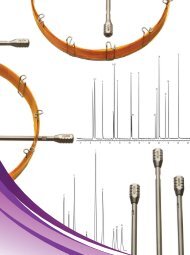
Figure 12.<br />
A low desorb flow can produce tailing peaks, as in this example, desorbed at 9mL/min.<br />
EPA Method 8020, Rtx<br />
1<br />
3<br />
1. benzene<br />
2. α,α,α-trifluorotoluene (SS)<br />
3. toluene<br />
4. ethylbenzene<br />
5. m-xylene<br />
6. p-xylene<br />
7. o-xylene<br />
2<br />
® -5Sil MS column, 40m, 0.45mm ID, 1.5µm (cat. #12798)<br />
Carrier gas: 9mL/min. @ constant pressure<br />
GC: Finnigan 9001<br />
Detector: FID<br />
Oven temp.: 40°C (hold 2 min.)<br />
85°C @ 4°C/min.<br />
(hold 1 min.) to<br />
225°C @ 40°C/min.<br />
(hold 2 min.)<br />
min. 3.50 4.50 5.50 6.50 7.50 8.50 9.50 10.50 11.50<br />
4<br />
5,6<br />
7<br />
Wastewater samples commonly<br />
contain surfactants and o<strong>the</strong>r<br />
material that can contaminate<br />
<strong>the</strong> concentrator.<br />
17<br />
www.restekcorp.com