Chapter 3 The applicability of LEFM - Division of Solid Mechanics
Chapter 3 The applicability of LEFM - Division of Solid Mechanics
Chapter 3 The applicability of LEFM - Division of Solid Mechanics

You also want an ePaper? Increase the reach of your titles
YUMPU automatically turns print PDFs into web optimized ePapers that Google loves.
<strong>Chapter</strong> 3<br />
<strong>The</strong> <strong>applicability</strong> <strong>of</strong> <strong>LEFM</strong><br />
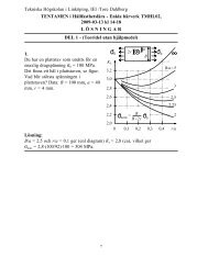
3.1 Crack tip plasticity<br />
3.1.1 Behaviour at the crack tip;<br />
plane stress, plane strain or mixed conditions<br />
According to linear elasticity (c.f. previous section), we have in front <strong>of</strong> the<br />
crack tip (θ = 0) the following generalized bi-axial stress state<br />
σ x = σ y =<br />
K I<br />
√<br />
2πr<br />
(3.1)<br />
σ z = 0 (plane stress) or σ z = ν(σ x + σ y )(plane strain) (3.2)<br />
τ xy = τ yz = τ zx = 0 (3.3)<br />
Clearly, due to the high tensile in-plane normal stresses, the material will<br />
contract in the thickness direction. However, the extent to which it will do<br />
so depends on the constraint due to the surrounding material. Considering a<br />
through thickness crack in a plane body, it is clear that a large thickness will<br />
prohibit contraction (plane strain condition), except at the surface, where a<br />
plane stress state will exist. For a thin specimen on the other hand, plane<br />
stress conditions will prevail throughout the thickness, for an illustration, see<br />
Fig.3.1 below. For an inner crack on the other hand, a plane strain situation<br />
will generally prevail at the crack tip.<br />
Now, why is this interesting? Well, the answer is that the condition in the<br />
thickness direction will affect the size <strong>of</strong> the plastic zone that inevitably will<br />
be found at crack tips in metallic materials.<br />
23
Figure 3.1: Plane strain and plane stress conditions<br />
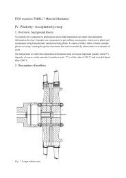
3.1.2 General plastic behaviour at bi-axial loading<br />
for plane stress and plane strain conditions<br />
Let us consider a flat specimen which is subjected to the in-plane bi-axial<br />
applied stress σ 0 , and which obeys the Tresca yield condition (used for simplicity).<br />
With the yield criterion<br />
where<br />
in combination with the prevailing loading<br />
σ eT = σ Y (3.4)<br />
σ eT = σ 1 − σ 3 (σ 1 ≥ σ 2 ≥ σ 3 ) (3.5)<br />
σ 1 = σ 2 = σ x = σ y = σ 0 (3.6)<br />
σ 3 = σ z (3.7)<br />
we get plastic yielding when<br />
⎧<br />
⎨σ Y<br />
plane stress<br />
σ 0 = 1<br />
⎩<br />
1 − 2ν σ Y ≈ 3σ Y plane strain<br />
(3.8)<br />
As can be seen, plane strain conditions will restrict the plastic flow under<br />
bi-axial loading conditions.<br />
24
3.1.3 Crack tip behavior and <strong>applicability</strong> <strong>of</strong> <strong>LEFM</strong>;<br />
a first discussion<br />
Since a generalized bi-axial stress state is prevailing at the crack tip, and since<br />
the associated plastic flow behaviour strongly depends on the constraint in<br />
the thickness direction, it follows from the above discussion, that the size<br />
<strong>of</strong> the plastic zone will be smaller under plane strain conditions than under<br />
plane stress conditions. Furthermore, for the case <strong>of</strong> a through-thickness<br />
crack in a flat specimen, the plastic zone size will be larger for a thin specimen<br />
than for a thicker one.<br />
Now, as long as the plastic zone is small compared to the crack length, it<br />
may be argued (and motivated by the success <strong>of</strong> <strong>LEFM</strong>) that K governs the<br />
occurrence <strong>of</strong> fracture (and as we shall see later on, the fatigue crack growth<br />
behaviour). Thus, we we would like to find an estimation <strong>of</strong> the plastic zone<br />
size and, based on that, set up a criterion for the <strong>applicability</strong>/validity <strong>of</strong><br />
<strong>LEFM</strong>.<br />
3.1.4 <strong>The</strong> Irwin approach<br />
<strong>The</strong> first simple approach for finding the plastic zone size, with focus on its<br />
length r p in the direction <strong>of</strong> the crack (θ = 0), is to start with the linearelastic<br />
solution for the crack tip stresses, and to state that r p is given by<br />
σ el.sol<br />
y (r p ) = ασ Y (3.9)<br />
where the factor α is equal to 1 for plane stress conditions and equal to 3 (or<br />
less, see subsequent discussion) for plane strain conditions, resp. However,<br />
such an approach will be erroneous, since we will then “miss” part <strong>of</strong> the<br />
area below the stress component curve. Irwin solved this problem, by simply<br />
translating the elastic stress-curve to the right, and calculated the corrected<br />
plastic zone size by the relation<br />
∫ r1<br />
0<br />
σ y (r)dr =<br />
∫ rp<br />
0<br />
ασ Y dr (3.10)<br />
where r 1 is the uncorrected plastic zone length, c.f. Fig.3.2 below. To see<br />
this, we note that<br />
A 1 = A ′ 1<br />
A 3 = A ′ 3<br />
⇒ A 2 = A ′ 2 ⇒ A 1 + A 2 = A ′ 1 + A ′ 2<br />
25
Figure 3.2: Approximation <strong>of</strong> the plastic zone size according to Irwin<br />
By the above relation we get<br />
K I<br />
√<br />
2π<br />
∫ r1<br />
0<br />
K I<br />
1<br />
√ r<br />
(r)dr = ασ Y r p ⇒<br />
√<br />
2π<br />
2 √ r 1 = ασ Y r p ⇒<br />
r p =<br />
√<br />
2KI<br />
√<br />
r1<br />
√ πασY<br />
(3.11)<br />
Furthermore,<br />
σ y (r 1 ) = ασ Y ⇒<br />
K I<br />
√ 2πr1<br />
= ασ Y ⇒<br />
√<br />
r1 =<br />
K I<br />
√<br />
2πασY<br />
⇒<br />
implying<br />
r 1 = 1 ( ) 2 KI<br />
(3.12)<br />
2π ασ Y<br />
r p =<br />
√<br />
2KI<br />
√ πασY<br />
K I<br />
√<br />
2πασY<br />
i.e.<br />
r p = 1 π<br />
(<br />
KI<br />
ασ Y<br />
) 2<br />
(3.13)<br />
As can be seen, the corrected plastic zone size (r p ) is, according to Irwin’s<br />
analysis, twice the size <strong>of</strong> the uncorrected one (r 1 ).<br />
26
3.2 Applicability <strong>of</strong> <strong>LEFM</strong><br />
It was found above, that<br />
r p = 1 π<br />
(<br />
KI<br />
ασ Y<br />
) 2<br />
(3.14)<br />
In order to ensure the <strong>applicability</strong> <strong>of</strong> <strong>LEFM</strong>, we know that the plastic zone<br />
size needs to be small compared to the crack length. More quantitatively,<br />
for <strong>LEFM</strong>-testing <strong>of</strong> K Ic -values, the American Society for Testing and Materials<br />
(ASTM) state the following requirements for critical dimensions <strong>of</strong> the<br />
test specimens (typically, Single Edge Notched Bend/SENB specimens, or<br />
Compact Tension/CT specimens)<br />
the ASTM criterion for K Ic testing<br />
⎧ ⎫<br />
⎨ a ⎬ ( ) 2<br />
t<br />
⎩ ⎭ ≥ 2.5 KIc<br />
(3.15)<br />
σ<br />
W − a<br />
Y<br />
where the second requirement assures plane strain conditions and the third<br />
requirement assures that no excessive plastic flow will take place in the uncracked<br />
ligament.<br />
It may be noted that with the original proposal α = √ 3 by Irwin for plane<br />
strain conditions, the ASTM condition requires that the crack length is to<br />
be approximately 25 times larger than the plastic zone at the time <strong>of</strong> fracture.<br />
In some literature (some course books and some handbooks) it is argued<br />
that the ASTM condition is to be used as a general criterion for the <strong>applicability</strong><br />
<strong>of</strong> <strong>LEFM</strong>, where the thickness criterion makes sure that K Ic may be<br />
used as a relevant value for the fracture toughness, and where the size <strong>of</strong> the<br />
unfractured ligament makes sure that no excessive plastic deformation has<br />
taken place. However, <strong>LEFM</strong> can also be used for plane stress situations, as<br />
long as the plastic zone is small compared to the crack length, and as long<br />
as a relevant value for the fracture toughness at plane stress K c /K 1c (> K Ic )<br />
is used.<br />
27
3.3 Some further comments<br />
Another approach for finding the size <strong>of</strong> the plastic zone is the one by Dugdale<br />
(the so called strip yield model), where the plastic zone size is found by<br />
superimposing elemental cases; similar results as for the Irwin approach are<br />
found for cases <strong>of</strong> small scale yielding. By the Dugdale-approach, fracture<br />
formulas based on the Crack (Tip) Opening Displacements/C(T)OD can also<br />
be formulated, which find their major use in Elasto-Plastic Fracture <strong>Mechanics</strong><br />
(EPFM).<br />
It should also be mentioned that it has been proposed to use Irwin’s results<br />
to correct the crack length in cases where the crack-length condition<br />
for <strong>LEFM</strong> is not fulfilled. This may be seen as an attempt to avoid EPFM.<br />
However, we will not enter into that details here.<br />
28
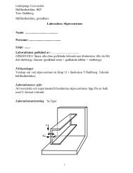
3.4 Questions<br />
3.1) Check if <strong>LEFM</strong> , according to the ASTM criterion, is applicable in the<br />
introductory example in Ch.1, Introduction?<br />
Answer: All critical dimensions are larger than 1.4 cm, thus <strong>LEFM</strong> is OK!<br />
3.2) Check if <strong>LEFM</strong> , according to the ASTM criterion, is applicable in<br />
Question 2.4) in Ch.2 ? Assume that t = 1.5cm and that σ Y = 1200MP a.<br />
Answer: All critical dimensions are larger than 1.1 cm, thus <strong>LEFM</strong> is OK!<br />
3.3) Do problem 2.12 in the book by Dahlberg & Ekberg!<br />
3.4) Calculate the maximum load that the linearly elastic detail shown below<br />
can withstand withoput cracking! <strong>The</strong> validity <strong>of</strong> <strong>LEFM</strong> is to be checked<br />
w.r.t. the ASTM criterion!<br />
Answer: P c = 2.8MN, All critical dimensions are larger than 1.8 cm, thus<br />
<strong>LEFM</strong> is OK!<br />
29