2003-01-18 - Division of Solid Mechanics
2003-01-18 - Division of Solid Mechanics
2003-01-18 - Division of Solid Mechanics

You also want an ePaper? Increase the reach of your titles
YUMPU automatically turns print PDFs into web optimized ePapers that Google loves.
Avd Hållfasthetslära, IKP, Linköpings Universitet<br />
Tentamen TMHL61<br />
Tentamen i Skademekanik och livslängdsanalys TMHL61<br />
lördagen den <strong>18</strong>/1 <strong>2003</strong>, kl 14-<strong>18</strong><br />
<strong>Solid</strong> <strong>Mechanics</strong>, IKP, Linköping University<br />
Examination in Damage <strong>Mechanics</strong> and Life Analysis TMHL61<br />
Saturday, January <strong>18</strong>, <strong>2003</strong>, time: 14-<strong>18</strong><br />
Teacher: Tore Dahlberg, <strong>01</strong>3-28 1116, or 070-66 511 03.<br />
Examination<br />
Part I<br />
Part II<br />
Part I (yellow papers): No books or other external facilities are allowed.<br />
The questions should be answered directly on the yellow papers.<br />
After having handed in Part I (the four yellow papers), Part II (white<br />
papers) is received. The following literature may then be used:<br />
Literature 1. T Dahlberg and A Ekberg: Failure, Fracture, Fatigue - An<br />
Part II Introduction, or T Dahlberg and A Ekberg: Fatigue and Fracture<br />
Design, LiTH-IKP-S-493<br />
2. Sundström B: Handbok och formelsamling i hållfasthetslära, KTH,<br />
1998 (or G Hedner (ed): KTH Formelsamling i Hållfasthetslära) and/or<br />
extractions from these handbooks (for English-speaking students).<br />
3. Handbooks and mathematical tables, dictionaries, glossary.<br />
4. Any small, handhold calculator in one single unit and without any<br />
external communication (as printer, tape-recorder or others).<br />
In the literature minor notations "in the margin" are allowed, but no<br />
problems, solutions, or answers to problems are allowed.<br />
Language<br />
Solutions<br />
Results<br />
Student’s<br />
inspection<br />
Marks/grades<br />
Solutions can be given in Swedish or English.<br />
Solutions will be posted on the notice-board <strong>of</strong> <strong>Solid</strong> <strong>Mechanics</strong><br />
(Hållfasthetsläras), entrance 15 or 17, corridor B, at <strong>18</strong>.00. Solutions<br />
will be available also on the web at http://www.solid.ikp.liu.se, under<br />
the heading "Examinations".<br />
Examination results will be posted on the same notice-board not later<br />
that January 30, <strong>2003</strong>.<br />
The correction <strong>of</strong> the examination papers is open for inspection until<br />
February 28, <strong>2003</strong>. After this date the exams are distributed to the<br />
students.<br />
To obtain a mark (grade), the examination and the laboratory work<br />
should be passed<br />
Points 0 to 5 6 to 8 9 to 11 12 to 16<br />
Mark failed 3 4 5<br />
NOTE! This page need not be handed in. Keep it to remember the dates and information given.<br />
Tore Dahlberg, Hållfasthetslära, tel <strong>01</strong>3-28 1116 <strong>2003</strong>-<strong>01</strong>-23
Examination in Damage <strong>Mechanics</strong> and Life Analysis (TMHL61)<br />
LiTH <strong>2003</strong>-<strong>01</strong>-<strong>18</strong><br />
Part 1<br />
1. (1 point)<br />
When working with tensor notations, the Kronecker delta, δ ij , is <strong>of</strong>ten very useful.<br />
Explain the use and meaning <strong>of</strong> this symbol.<br />
Solution and answer here:<br />
The symbol δ ij is defined as a tensor with the following property:<br />
δ ij = ⎧ 0 if i ≠ j<br />
⎨<br />
1 if i = j<br />
Indexes i and j stand for the three coordinate directions (x, y, z) or (r, Θ, z) or (1, 2, 3)<br />
and so on.<br />
2. (1 point)<br />
Explain the phenomenon plastic instability.<br />
Solution and answer here:<br />
When a bar is loaded so that yielding occurs, it will be more narrow (cross-sectional<br />
area will decrease), and, due to the plastic deformation, there will be plastic hardening<br />
(deformation hardening) <strong>of</strong> the material. When loading the bar, plastic instability occurs<br />
when the deformation hardening ("increase <strong>of</strong> yield limit") can not compensate for the<br />
area reduction <strong>of</strong> the cross section.<br />
6 <strong>2003</strong>-<strong>01</strong>-23/TD
Examination in Damage <strong>Mechanics</strong> and Life Analysis (TMHL61)<br />
LiTH <strong>2003</strong>-<strong>01</strong>-<strong>18</strong><br />
Part 1<br />
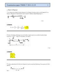
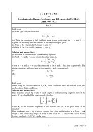
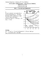
3. (1 point) Constant-amplitude fatigue strengths for materials<br />
subjected to different cyclic loading conditions are<br />
<strong>of</strong>ten expressed in Haigh diagrams. Consider the five<br />
a<br />
loading cases where the loading varies sinusoidally<br />
A<br />
and<br />
1. the mean value σ m is constant,<br />
200<br />
100<br />
B 2. the amplitude σ a is constant,<br />
3. the maximum value σ max (= σ m + σ a ) is constant,<br />
0<br />
0<br />
m<br />
100 200 300 400 MPa<br />
4. the minimum value σ min (= σ m − σ a ) is constant,<br />
and<br />
5. the stress ratio R = σ min /σ max is constant.<br />
In the Haigh diagram given, two straight lines (A<br />
and B) are shown. For each line one <strong>of</strong> the five<br />
loading conditions applies.<br />
(a) Determine which one <strong>of</strong> the five loading variables is constant for line A shown in<br />
the figure (i.e., match line A to one <strong>of</strong> the five loading conditions). Explain your choice.<br />
(b) Determine which one <strong>of</strong> the five loading variables is constant for line B shown in<br />
the figure (i.e., match line B to one <strong>of</strong> the five loading conditions). Explain your choice.<br />
Solution and answer here:<br />
For line A one notices that σ m + σ a is a constant (= 300 MPa). Thus, line A gives that<br />
stress σ max is constant.<br />
For line B one notices that σ m − σ a = σ min is constant (= 200 MPa). Thus, stress σ min is<br />
constant.<br />
Answer:<br />
(a) Line A: stress σ max is constant, (b) line B: stress σ min is constant.<br />
4. (1 point)<br />
To determine the fatigue limit <strong>of</strong> a material, the so-called stair-case method is<br />
sometimes used. Explain the principles, requirements and assumptions <strong>of</strong> this method<br />
(no formulas are needed).<br />
Solution and answer here:<br />
The fatigue testing is performed so that if a test specimen fails (due to fatigue), the next<br />
specimen will be tested at a lower stress level. If it does not fail (becomes a run-out),<br />
the next specimen will be tested at a higher stress lever. Then, assuming that the yield<br />
limit has a normal distribution, and knowing the number <strong>of</strong> failures and run-outs at each<br />
stress level, the mean value and the standard deviation <strong>of</strong> the fatigue limit can be<br />
estimated. This requires that tests performed at a stress level too far away from the<br />
mean value should be rejected.<br />
7 <strong>2003</strong>-<strong>01</strong>-23/TD
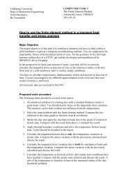
5. (3 points)<br />
( ) 0<br />
Examination in Damage <strong>Mechanics</strong> and Life Analysis (TMHL61)<br />
LiTH <strong>2003</strong>-<strong>01</strong>-<strong>18</strong><br />
y<br />
2 a<br />
2 W<br />
P<br />
x<br />
Part 2<br />
A large thin plate contains a through-thickness crack<br />
with initial crack length 2a 0 = 15 mm. The plate is<br />
loaded by a force P. Upon loading the plate,<br />
symmetric stable crack growth was observed. At load<br />
P = 300 kN the plate fractured. During the loading<br />
the crack opening δ(0) was recorded, and just prior to<br />
the fracture, the crack opening displacement was<br />
found to be δ(0) = 0.1 mm.<br />
Use the Dugdale model to determine the crack length<br />
just before the plate fractured.<br />
P<br />
Numerical data: Modulus <strong>of</strong> elasticity E = 210 GPa, yield strength σ Y = 480 MPa, plate<br />
width 2W = 0.4 m and plate thickness t = 0.002 m (i.e. the plate is so thin that the<br />
conditions at the crack tip may be regarded as plane stress).<br />
Solution:<br />
The load P = 300 kN gives stress σ ∞ = P/2Wt = 375 MPa in the plate.<br />
Since plane stress is at hand, the Dugdale model may be used. It gives<br />
δ(0) = 8 σ Y a 1 + sin(πσ<br />
E π<br />
ln⎧ ∞ /2σ Y ) ⎫<br />
⎨<br />
cos(πσ ∞ /2σ Y )<br />
Enter the given numerical values and solve for the unknown crack (half-)length a = a crit .<br />
One then obtains<br />
a crit<br />
= δ(0) E π ⎛ ⎜⎝ ln 1 + sin(πσ ∞/2σ Y ) ⎞<br />
⎟<br />
8 σ Y cos(πσ ∞ /2σ Y ) ⎠<br />
− 1<br />
210 000 ⋅ π ⎛ 1 + sin(π ⋅ 375/2 ⋅ 480) ⎞<br />
= 0, 00<strong>01</strong> ⎜ln ⎟ = 0, 0098 m<br />
8 ⋅ 480 ⎝ cos(π ⋅ 375/2 ⋅ 480) ⎠<br />
Thus, the total crack length at failure is 2a crit = 19.6 mm (= 1.31⋅2a 0 ).<br />
− 1<br />
⎬<br />
⎭<br />
8 <strong>2003</strong>-<strong>01</strong>-23/TD
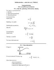
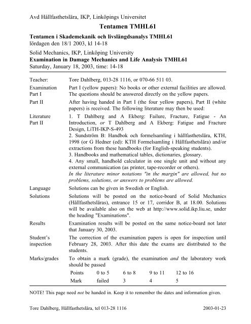
6.<br />
2 h<br />
Examination in Damage <strong>Mechanics</strong> and Life Analysis (TMHL61)<br />
LiTH <strong>2003</strong>-<strong>01</strong>-<strong>18</strong><br />
a<br />
a<br />
a<br />
Q<br />
P<br />
P<br />
Q<br />
M<br />
b<br />
2h<br />
2h<br />
b<br />
Part 2<br />
Determine, by use <strong>of</strong> superposition <strong>of</strong> stress intensity<br />
factors, the stress intensity factor K I for the split<br />
beam with a long crack, see figure. The crack length<br />
is a, beam thickness is b and beam height is 2h,<br />
where a >> b and a >> h. The material is linear<br />
elastic with modulus <strong>of</strong> elasticity E. The beam is<br />
loaded symmetrically with two opposite forces P at<br />
the beam ends. The sliding boundary condition to<br />
the right is such that the slope <strong>of</strong> the beam end is<br />
always zero. Assume plane stress conditions.<br />
The following results, taken from Problems 5/2 and<br />
5/3 in the textbook can be used:<br />
Double cantilever beam with stress intensity factor<br />
K I = 2 Qa / bh<br />
Double cantilever beam with energy release rate G =<br />
12M 2 / Eb 2 h 3<br />
Solution:<br />
First, remove the boundary condition to the right and add a bending moment M at the<br />
beam end. The bending moment M should be such that the slope at the free end <strong>of</strong> the<br />
cantilever beam is zero. One obtains, for slope Θ,<br />
a<br />
Q<br />
M<br />
M<br />
√⎺3<br />
which gives M = Qa / 2, and here Q = P<br />
Problem 5/3 gives, for plane stress, that K M I = = 2 M / bh<br />
Now superposition can be used to calculate the stress intensity factor in the case asked<br />
for. One obtains, using M = Qa / 2 and Q = P,<br />
K I = K I Q − K I M = 2 √⎺3 Qa<br />
bh√⎺h<br />
√⎺h<br />
Θ = Q a 2<br />
2EI − M a = 0<br />
EI<br />
√⎺⎺⎺EG √⎺3 √⎺h<br />
− 2 √⎺3 M<br />
bh√⎺h = 2 √⎺3 Qa<br />
bh√⎺h<br />
− 2 √⎺3 Qa<br />
2bh√⎺h = √⎺ 3 Qa<br />
bh√⎺h = √⎺ 3 Pa<br />
bh√⎺h<br />
9 <strong>2003</strong>-<strong>01</strong>-23/TD
Examination in Damage <strong>Mechanics</strong> and Life Analysis (TMHL61)<br />
LiTH <strong>2003</strong>-<strong>01</strong>-<strong>18</strong><br />
7. (3 points) One type <strong>of</strong> test specimen to determine the<br />
p<br />
fracture toughness <strong>of</strong> a material is the double<br />
cantilever beam, see figure. The height is 2h<br />
= 30 mm (the width t is large).<br />
At plane strain, the stress intensity factor can<br />
2 h be written<br />
p<br />
a<br />
where ν is the Poisson ratio, ν = 0.3, and p is<br />
the loading per unit <strong>of</strong> the width <strong>of</strong> the test<br />
specimen.<br />
Paris’ law for the material reads da<br />
dN = 5.1 × 10 − 12 (∆ K I ) 3<br />
m per cycle<br />
where ∆K I has the unit MPa m 1/2 .<br />
The fracture toughness <strong>of</strong> the material is (in this example) determined in the following<br />
way: First a crack <strong>of</strong> length a 0 = 20 mm is created by machining. Then, to obtain a<br />
sharp crack tip, the test specimen is subjected to a loading p such that the load p is<br />
cycled between 0 och 0.9 MN/m. This is done for N = 15 000 cycles. When this is done<br />
the cyclic loading is stopped.<br />
(a) Calculate the crack length a final obtained by the cyclic loading.<br />
After this, the test specimen is loaded by a static, monotonically increasing load p until<br />
fracture occurs. One obtains the final fracture <strong>of</strong> the specimen at load p = 1.8 MN/m.<br />
(b) Determine the fracture toughness <strong>of</strong> the material.<br />
The yield limit <strong>of</strong> the material is σ s = σ Y = 1000 MPa.<br />
Solution: (a) First determine the crack length after the cyclic loading. Paris’ law gives<br />
Which gives<br />
da<br />
dN = 5.1 × 10 ⎛ 3<br />
− 12 2√⎺3 0.9 a ⎞<br />
⎜ ⎟⎠ ⎝ 0.91 0.<strong>01</strong>5 3 / 2<br />
1 ⎧<br />
− 2<br />
from which is solved a final = 25.754 mm.<br />
(b) At the final, monotonically increasing loading the critical crack length is a final =<br />
25.754 mm. The fracture toughness is obtained from<br />
K I = K Ic = 2 √⎺3 p failure a final<br />
= 96.06 MPa√⎺m<br />
1 − ν 2 h 3/2<br />
Thus K Ic = 96 MPa m 1/2 .<br />
Here linear elastic fracture mechanics (LEFM) was used. Was it allowed?<br />
One has<br />
2.5 ⎛ 2<br />
K Ic ⎞<br />
⎜ ⎟⎠ = 2.5 ⎛ 2<br />
96 ⎞<br />
⎜ ⎟ = 0.023 m < a ⎝ σ Y ⎝ 1000⎠<br />
final = 0.02575 m<br />
Thus, it was OK to use LEFM for the final failure.<br />
⎨<br />
<br />
a final<br />
m per cycle<br />
K I = 2 √⎺3<br />
1 − ν 2 p a<br />
h 3/2<br />
1<br />
− 1 ⎫<br />
⎬<br />
2 2<br />
a = 0.033078 ⋅ N = 496.16 0 ⎭ (1/m2 )<br />
10 <strong>2003</strong>-<strong>01</strong>-23/TD
Examination in Damage <strong>Mechanics</strong> and Life Analysis (TMHL61)<br />
LiTH 2002-10-2<br />
Part 2<br />
8. (3 points)<br />
To determine the fatigue limit <strong>of</strong> a material a number <strong>of</strong> experiments were performed<br />
according to the "staircase" method. Calculate an estimation <strong>of</strong> the mean value and the<br />
standard deviation <strong>of</strong> the fatigue limit <strong>of</strong> the material if the following test series were<br />
obtained (stresses in MPa)<br />
σ a = 90, 99, 108, 117, 126, 117, 108, 117, 126, 117, 126, 135, 126, 117, 108, 117, 126,<br />
117, 126, 117, 108, 117 MPa,<br />
where the last test (117 MPa) became a run-out. The fatigue limit is supposed to have a<br />
normal distribution.<br />
Solution:<br />
From the load levels used in the test it is concluded that the test specimens failed<br />
(indicated by an F) or did not fail (became run-outs, indicated by RO) as follows:<br />
σ a = 90(RO), 99(RO), 108(RO), 117(RO), 126(F), 117(F), 108(RO), 117(RO), 126(F),<br />
117(RO), 126(RO), 135(F), 126(F), 117(F), 108(RO), 117(RO), 126(F), 117(RO),<br />
126(F), 117(F), 108(RO), 117(RO) MPa.<br />
The test series seems to have started on a too low stress level. Therefore, from the 22<br />
tests the first three tests are discarded (the first change from run-out to failure came at<br />
stress level 117 MPa). From the remaining 19 tests 10 are run-outs and 9 are failures.<br />
The less frequent event should be analysed. Thus, analyse the failures. The failures<br />
occurred at<br />
σ a = 126(F), 117(F), 126(F), 135(F), 126(F), 117(F), 126(F), 126(F), 117(F) MPa.<br />
These events give the following table (see compendium)<br />
I II III IV V<br />
117 0 3 0 0<br />
126 1 5 5 5<br />
135 2 1 2 4<br />
N = 9 A = 7 B = 9<br />
The mean value <strong>of</strong> the fatigue limit is estimated to (step d = 9 MPa)<br />
S’ m = S 0 + d ⎧ A<br />
⎨<br />
N − 1 ⎫<br />
⎬<br />
2<br />
= 117 + 9 ⎧ 7<br />
⎨<br />
⎭ 9 − 1 ⎫<br />
⎬ = 120 MPa<br />
2⎭ Further, one obtains<br />
NB − A 2<br />
= 9 ⋅ 9 − 72<br />
= 0.395<br />
N 2 9 2<br />
The standard deviation <strong>of</strong> the fatigue limit is estimated to<br />
s’ = 1.62d ⎧ NB − A 2<br />
⎨ + 0.029 ⎫ ⎬ = 6.2 MPa<br />
⎭<br />
N 2<br />
11 <strong>2003</strong>-<strong>01</strong>-23/TD