SOLEN INC.
SOLEN INC.
SOLEN INC.

Create successful ePaper yourself
Turn your PDF publications into a flip-book with our unique Google optimized e-Paper software.
<strong>SOLEN</strong> <strong>INC</strong>.<br />
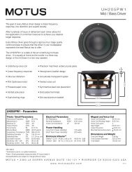
AIR CORE INDUCTORS<br />
PERFECT LAY HEXAGONAL WINDING<br />
<strong>SOLEN</strong> was the first electronic passive components manufacturing company to design air core inductors<br />
using the high precision honeycomb structured perfect lay hexagonal winding technique. This advance concept<br />
was introduced to design and manufacture the most complete line of highest quality close tolerance self<br />
supporting air core inductors for the specific application of the loudspeaker industry. The range of values is from<br />
0.10 mH to 30 mH with solid conductor sizes from 0.8 mm Ø (20AWG) to 2.6 mm Ø (10AWG) with a tolerance of<br />
0.5 %.<br />
< Inductor<br />
Inductor, also called coil, is a passive device consisting of a number of turns of conductor that introduce<br />
an inductive reactance due to inductance into an electrical circuit to produce a magnetic flux. The parameters that<br />
characterize an inductor are the inductance (L) and the quality factor (Q). In addition the d.c. resistance (R) and<br />
the a.c. resistance (R f ) can also be useful parameters as well.<br />
< Inductance L (H)<br />
The inductance of an inductor depends on the number of turns, diameter of the inductor, the length of the<br />
inductor and the nature of the core. The electrical size of an inductor is called inductance (L) and is expressed in<br />
Henrys (H). It is the property of a circuit that tends to oppose any change of current because of magnetic field<br />
associated with the current itself.<br />
< Inductive Reactance X L = 2 * B * f * L<br />
It is a positive reactance due the inductance of an inductor<br />
< Quality Factor Q<br />
The quality factor is the ratio of the reactance to the resistance and therefore is unit less. The higher the<br />
quality factor, the fewer the losses there are in the inductor. The dissipation factor (D) can be referred to as the<br />
total loss within a components and it is defined as 1 / Q. The total loss (D) of an air core inductor is comprised of<br />
winding copper loss, winding eddy-current loss and conductor skin effect loss. The total loss (D) of a magnetic<br />
core inductor is comprised of winding copper loss, winding eddy-current loss and conductor skin effect loss with<br />
the addition the magnetic core eddy-current loss and magnetic core hysteretic loss.<br />
< Impedance Z (S / f)<br />
The opposition that an inductor offers to alternating current is called impedance (Z) and it is expressed in<br />
ohms (Ω f). The impedance of an inductor increases with frequency.<br />
< Air Core Inductors<br />
Air core inductors are the only one that can achieve pure inductance ideal inductive reactance behavior.<br />
They have the highest stability, the tightest tolerance, a linear inductance under dynamic signal condition, greater<br />
power handling and less distortion. They have relatively low d.c. resistance, linear a.c. resistance, better and more<br />
linear quality factor at high frequency and linear phase characteristics. They also have no magnetic core hysteretic<br />
distortion, no magnetic core saturation distortion, no magnetic core non-linear inductance and no magnetic core<br />
phase distortion. They produce no harmonics frequency. Air core also means larger inductors and a higher d.c.<br />
resistance compare to magnetic core inductor.
Wheeler’s Formula L (:H) = ( 0.0315 *a 2 * N 2 ) / ( 6 *a + 9*l + 10 *c ) l w = 2 * B * N * a<br />
N = number of turns, (mm) a = average coil radius, l = coil length, c = coil thickness, l w = length of wire<br />
This accurate formula that calculate the inductance in micro henries, for multi layer air core inductors was<br />
used and integrated in a computer program to efficiently evaluate each specific inductor design for optimum size<br />
and lowest possible d.c. resistance for any given inductance value and wire size. After the most promising<br />
designs were identified, they were merged and incorporated in a series of 12 different optimum inductor<br />
dimensions (l x d x D were l = coil length, were the inside diameter d = 2c and were the outside diameter D = 4c)<br />
in order to cover the whole range of the inductance values and wire size ranges. The accuracy is within 1% when<br />
the three terms in the denominator are about equal.<br />
< Winding D.C. Resistance R dc (S) = 4 * ρ c * N * 2 * π * a / π * d w<br />
2<br />
ρ c = conductor resistivity (copper = 1.709 x 10 -8 Ωm), d w = diameter of wire<br />
This general formula calculates the d.c. resistance in ohms for the above multi layer air core inductor.<br />
Another formula, R dc (S) = 7.67 * a * N 2 / 10 6 * l * c, calculates the d.c. resistance in ohms for the above multi<br />
layer air core inductor with a single enamel coating circular copper conductor and a space factor of 90% for the<br />
winding.<br />
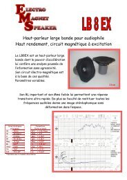
< Hexagonal Winding<br />
The standard air core inductor using low precision machine wound type which produces either a random<br />
or a square type loose winding, self supporting or not, was not acceptable. Close tolerance proprietary custom<br />
designed winding tooling were research and developed as the only way to achieve the high precision honeycomb<br />
structured perfect lay hexagonal winding technique. The finish product is a multi layer self supporting air core<br />
inductor with an extremely tight hexagonal honeycomb structured maximum filled winding area that delivers the<br />
best possible winding space factor for any given inductor value with the highest possible quality factor.<br />
< Electro Mechanical Vibration<br />
The alternating current passing through an inductor will induce an alternating magnetic field, which will<br />
produce a mechanical vibration in each turn of wire corresponding the applied audio frequency. This mechanical<br />
vibration generates an acoustic radiation that will cause a non-linear loss and distortion under the form of an audio<br />
frequency noise. The high precision perfect lay hexagonal winding technique with its tight hexagonal honeycomb<br />
structured winding cut most of these electro mechanical vibration losses. Furthermore, each inductor is dipped in<br />
an industrial varnish that impregnates perfectly and totally solidifies all the outside turns.<br />
< Perfect Layer Winder<br />
Advance technology, state of the art, perfect layer winding equipments along with a complete set of 12<br />
proprietary high precision self-supporting winding types tooling were custom designed, developed and<br />
manufactured by <strong>SOLEN</strong>. With this sophisticated manufacturing equipment and tooling, each turn of each layer is<br />
precisely winded side by side and each turn of all subsequent layers are alternatively offset from the underlying<br />
layer turn by a distance equal to the radius of the wire used, which means that each overlying turn of the second<br />
layer fits in the groove made by the underlying turn of the first layer, hence the term perfect lay.<br />
< Nec Plus Ultra<br />
All those optimized factors combine to give a much superior air core inductor with the best possible<br />
specifications: a higher quality factor, lower d.c. resistance, more linear a.c. resistance, lower electro mechanical<br />
vibration losses, closer tolerance, lower stray capacitance, longer stability, higher power handling, lowest distortion<br />
and the best sonic quality for any given inductor value. They are the nec plus ultra of today inductors because they<br />
were originally designed has a cost no object project and as a no compromise achievement.<br />
<strong>SOLEN</strong> 2008
<strong>SOLEN</strong> <strong>INC</strong>.<br />
AIR CORED INDUCTORS<br />
PERFECT LAY HEXAGONAL WINDING<br />
● GENERAL INFORMATION<br />
Type<br />
Conductor<br />
Dielectric<br />
Construction<br />
Winding<br />
Coating<br />
Leads<br />
: Air Cored Inductor.<br />
: Pure Copper Solid Round Type.<br />
: Red Polyurethane Polyamide Enamel.<br />
: Hollow Cylindrical Type, Radial Leads.<br />
: Perfect Layer Hexagonal Self-Supporting Type.<br />
: Varnish Dip With Four Black Nylon Ties.<br />
: Pure Copper<br />
● TECHNICAL DATA<br />
Inductance Range/Tolerance : 0.10 mH ... 30 mH, E24 series, ±1 %. (see specifications for details)<br />
Conductor Material<br />
: ≥ 99.99 % Purity Annealed Copper.<br />
Electrical Conductivity : ≥ 101.5 %.<br />
DC resistance<br />
: Very Low (see specifications for details)<br />
Oxygen Content<br />
: ≤ 200 ppm on surface.<br />
Temperature Coefficient : 0.00393 / °C.<br />
Temperature Range<br />
: -55 °C to +85 °C.<br />
Insulation Temperature : 130 °C.<br />
Solderable Temperature : 360 °C.<br />
Test Voltage<br />
: 1000 VAC<br />
Conductor Diameter<br />
: S20 = 0.8, S18 = 1.0, S16 = 1.3, S14 = 1.6, S12 = 2.0, S10=2.6mmØ<br />
Skin Effect Rac = Rdc<br />
: S20 = 7.0, S18 = 4.0, S16 = 2.5, S14 = 1.7, S12 = 1.0, S10 = 0.7 KHz<br />
Skin Effect Rac = Rdc +10% : S20 = 27, S18 = 17, S16 = 10, S14 = 7.0, S12 = 4.0, S10 = 2.5 KHz<br />
Winding Space Factor : S20 = 84, S18 = 86 , S16 = 87, S14 = 88, S12 = 90, S10 = 92 %<br />
● FEATURE<br />
Integral Wheeler Formula Application.<br />
Computer Optimized Inductor Dimension.<br />
Linear AC Resistance<br />
Very Low Magnetostriction Distortion.<br />
Constant Inductance with Voltage Variation.<br />
Constant Inductance with Current Variation.<br />
No Saturation Distortion.<br />
No Hyteresis Distortion.<br />
● ELECTRICAL PERFORMANCE<br />
High Quality Factor.<br />
Very Low DC Resistance<br />
Low AC Resistance.<br />
Low Skin Effect Losses.<br />
Low Proximity Effect Losses.<br />
Low Self Capacitance.
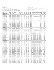
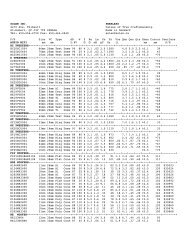
DC Resistance (Ohms) +5%<br />
Dimensions (mm) +10%<br />
S20 0.80 mm Ø / 20 AWG S18 1.02 mm Ø / 18 AWG S16 1.29 mm Ø / 16 AWG<br />
P/N Inductance/DCR LxdxD P/N Inductance/DCR LxdxD P/N Inductance/DCR LxdxD<br />
----------------------------- ----------------------------- -----------------------------<br />
S18.10 .10 mH .12 10x19x38 S16.10 .10 mH .08 11x22x45<br />
S18.11 .11 mH .13 10x19x38 S16.11 .11 mH .08 11x22x45<br />
S18.12 .12 mH .14 10x19x38 S16.12 .12 mH .09 11x22x45<br />
S18.13 .13 mH .15 10x19x38 S16.13 .13 mH .09 11x22x45<br />
S18.15 .15 mH .16 10x19x38 S16.15 .15 mH .10 11x22x45<br />
----------------------------- ----------------------------- -----------------------------<br />
S20.16 .16 mH .24 10x19x38 S18.16 .16 mH .16 11x22x45 S16.16 .16 mH .11 13x25x51<br />
S20.18 .18 mH .26 10x19x38 S18.18 .18 mH .17 11x22x45 S16.18 .18 mH .11 13x25x51<br />
S20.20 .20 mH .27 10x19x38 S18.20 .20 mH .18 11x22x45 S16.20 .20 mH .12 13x25x51<br />
S20.22 .22 mH .29 10x19x38 S18.22 .22 mH .19 11x22x45 S16.22 .22 mH .13 13x25x51<br />
S20.24 .24 mH .31 10x19x38 S18.24 .24 mH .21 11x22x45 S16.24 .24 mH .14 13x25x51<br />
S20.27 .27 mH .34 10x19x38 S18.27 .27 mH .22 11x22x45 S16.27 .27 mH .15 13x25x51<br />
S20.30 .30 mH .36 10x19x38 S18.30 .30 mH .24 11x22x45 S16.30 .30 mH .16 13x25x51<br />
----------------------------- ----------------------------- -----------------------------<br />
S20.33 .33 mH .38 11x22x45 S18.33 .33 mH .26 13x25x51 S16.33 .33 mH .16 14x29x57<br />
S20.36 .36 mH .40 11x22x45 S18.36 .36 mH .27 13x25x51 S16.36 .36 mH .17 14x29x57<br />
S20.39 .39 mH .42 11x22x45 S18.39 .39 mH .28 13x25x51 S16.39 .39 mH .18 14x29x57<br />
S20.43 .43 mH .44 11x22x45 S18.43 .43 mH .29 13x25x51 S16.43 .43 mH .19 14x29x57<br />
S20.47 .47 mH .47 11x22x45 S18.47 .47 mH .31 13x25x51 S16.47 .47 mH .21 14x29x57<br />
S20.51 .51 mH .49 11x22x45 S18.51 .51 mH .33 13x25x51 S16.51 .51 mH .22 14x29x57<br />
S20.56 .56 mH .51 11x22x45 S18.56 .56 mH .35 13x25x51 S16.56 .56 mH .23 14x29x57<br />
S20.62 .62 mH .54 11x22x45 S18.62 .62 mH .36 13x25x51 S16.62 .62 mH .24 14x29x57<br />
============================= ----------------------------- -----------------------------<br />
S20.68 .68 mH .57 13x25x51 S18.68 .68 mH .38 14x29x57 S16.68 .68 mH .25 16x32x64<br />
S20.75 .75 mH .60 13x25x51 S18.75 .75 mH .40 14x29x57 S16.75 .75 mH .27 16x32x64<br />
S20.82 .82 mH .63 13x25x51 S18.82 .82 mH .43 14x29x57 S16.82 .82 mH .28 16x32x64<br />
S20.91 .91 mH .66 13x25x51 S18.91 .91 mH .45 14x29x57 S16.91 .91 mH .30 16x32x64<br />
S201.0 1.0 mH .70 13x25x51 S181.0 1.0 mH .47 14x29x57 S161.0 1.0 mH .31 16x32x64<br />
S201.1 1.1 mH .75 13x25x51 S181.1 1.1 mH .50 14x29x57 S161.1 1.1 mH .33 16x32x64<br />
S201.2 1.2 mH .80 13x25x51 S181.2 1.2 mH .54 14x29x57 S161.2 1.2 mH .35 16x32x64<br />
S201.3 1.3 mH .85 13x25x51 S181.3 1.3 mH .57 14x29x57 S161.3 1.3 mH .38 16x32x64<br />
S201.5 1.5 mH .91 13x25x51 S181.5 1.5 mH .60 14x29x57 S161.5 1.5 mH .41 16x32x64<br />
----------------------------- ============================= -----------------------------<br />
S201.6 1.6 mH .96 14x29x57 S181.6 1.6 mH .63 16x32x64 S161.6 1.6 mH .44 19x38x76<br />
S201.8 1.8 mH 1.01 14x29x57 S181.8 1.8 mH .68 16x32x64 S161.8 1.8 mH .46 19x38x76<br />
S202.0 2.0 mH 1.05 14x29x57 S182.0 2.0 mH .70 16x32x64 S162.0 2.0 mH .48 19x38x76<br />
S202.2 2.2 mH 1.14 14x29x57 S182.2 2.2 mH .76 16x32x64 S162.2 2.2 mH .52 19x38x76<br />
S202.4 2.4 mH 1.20 14x29x57 S182.4 2.4 mH .81 16x32x64 S162.4 2.4 mH .56 19x38x76<br />
S202.7 2.7 mH 1.28 14x29x57 S182.7 2.7 mH .87 16x32x64 S162.7 2.7 mH .60 19x38x76<br />
S203.0 3.0 mH 1.36 14x29x57 S183.0 3.0 mH .93 16x32x64 S163.0 3.0 mH .63 19x38x76<br />
----------------------------- ----------------------------- =============================
S203.3 3.3 mH 1.43 16x32x64 S183.3 3.3 mH .98 19x38x76 S163.3 3.3 mH .66 22x45x89<br />
S203.6 3.6 mH 1.50 16x32x64 S183.6 3.6 mH 1.03 19x38x76 S163.6 3.6 mH .70 22x45x89<br />
S203.9 3.9 mH 1.57 16x32x64 S183.9 3.9 mH 1.09 19x38x76 S163.9 3.9 mH .73 22x45x89<br />
S204.3 4.3 mH 1.66 16x32x64 S184.3 4.3 mH 1.15 19x38x76 S164.3 4.3 mH .77 22x45x89<br />
S204.7 4.7 mH 1.75 16x32x64 S184.7 4.7 mH 1.22 19x38x76 S164.7 4.7 mH .82 22x45x89<br />
S205.1 5.1 mH 1.84 16x32x64 S185.1 5.1 mH 1.29 19x38x76 S165.1 5.1 mH .86 22x45x89<br />
S205.6 5.6 mH 1.93 16x32x64 S185.6 5.6 mH 1.36 19x38x76 S165.6 5.6 mH .91 22x45x89<br />
S206.2 6.2 mH 2.02 16x32x64 S186.2 6.2 mH 1.43 19x38x76 S166.2 6.2 mH .96 22x45x89<br />
----------------------------- ----------------------------- ------------------------------<br />
S186.8 6.8 mH 1.51 22x45x89 S166.8 6.8 mH 1.01 25x51x102<br />
S187.5 7.5 mH 1.59 22x45x89 S167.5 7.5 mH 1.07 25x51x102<br />
S188.2 8.2 mH 1.67 22x45x89 S168.2 8.2 mH 1.12 25x51x102<br />
S189.1 9.1 mH 1.75 22x45x89 S169.1 9.1 mH 1.18 25x51x102<br />
S1810 10 mH 1.84 22x45x89 S1610 10 mH 1.24 25x51x102<br />
S1811 11 mH 1.98 22x45x89 S1611 11 mH 1.38 25x51x102<br />
S1812 12 mH 2.12 22x45x89 S1612 12 mH 1.52 25x51x102<br />
S1813 13 mH 2.27 22x45x89 S1613 13 mH 1.66 25x51x102<br />
S1815 15 mH 2.42 22x45x89 S1615 15 mH 1.70 25x51x102<br />
----------------------------- ----------------------------- ------------------------------<br />
S1616 16 mH 1.79 32x64x127<br />
S1618 18 mH 1.88 32x64x127<br />
S1620 20 mH 1.97 32x64x127<br />
S1622 22 mH 2.07 32x64x127<br />
S1624 24 mH 2.17 32x64x127<br />
S1627 27 mH 2.27 32x64x127<br />
S1630 30 mH 2.37 32x64x127<br />
----------------------------- ----------------------------- ------------------------------
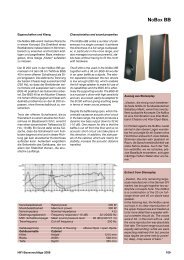
DC Resistance (Ohms) ±5%<br />
Dimensions (mm) ±10%<br />
S14 1.63 mm Ø / 14 AWG S12 2.05 mm Ø / 12 AWG S10 2.59 mm Ø / 10 AWG<br />
P/N Inductance/DCR LxdxD P/N Inductance/DCR LxdxD P/N Inductance/DCR LxdxD<br />
----------------------------- ----------------------------- -----------------------------<br />
----------------------------- ----------------------------- -----------------------------<br />
S14.16 .16 mH .07 14x29x57<br />
S14.18 .18 mH .08 14x29x57<br />
S14.20 .20 mH .08 14x29x57<br />
S14.22 .22 mH .09 14x29x57<br />
S14.24 .24 mH .10 14x29x57<br />
S14.27 .27 mH .10 14x29x57<br />
S14.30 .30 mH .11 14x29x57<br />
----------------------------- ----------------------------- -----------------------------<br />
S14.33 .33 mH .11 16x32x64 S12.33 .33 mH .07 19x38x76<br />
S14.36 .36 mH .11 16x32x64 S12.36 .36 mH .08 19x38x76<br />
S14.39 .39 mH .12 16x32x64 S12.39 .39 mH .08 19x38x76<br />
S14.43 .43 mH .12 16x32x64 S12.43 .43 mH .09 19x38x76<br />
S14.47 .47 mH .13 16x32x64 S12.47 .47 mH .10 19x38x76<br />
S14.51 .51 mH .14 16x32x64 S12.51 .51 mH .10 19x38x76<br />
S14.56 .56 mH .15 16x32x64 S12.56 .56 mH .11 19x38x76<br />
S14.62 .62 mH .16 16x32x64 S12.62 .62 mH .11 19x38x76<br />
----------------------------- ----------------------------- ------------------------------<br />
S14.68 .68 mH .17 19x38x76 S12.68 .68 mH .11 22x45x89 S10.68 .68 mH .08 25x51x102<br />
S14.75 .75 mH .18 19x38x76 S12.75 .75 mH .12 22x45x89 S10.75 .75 mH .09 25x51x102<br />
S14.82 .82 mH .19 19x38x76 S12.82 .82 mH .12 22x45x89 S10.82 .82 mH .09 25x51x102<br />
S14.91 .91 mH .20 19x38x76 S12.91 .91 mH .13 22x45x89 S10.91 .91 mH .10 25x51x102<br />
S141.0 1.0 mH .21 19x38x76 S121.0 1.0 mH .14 22x45x89 S101.0 1.0 mH .10 25x51x102<br />
S141.1 1.1 mH .23 19x38x76 S121.1 1.1 mH .15 22x45x89 S101.1 1.1 mH .11 25x51x102<br />
S141.2 1.2 mH .24 19x38x76 S121.2 1.2 mH .16 22x45x89 S101.2 1.2 mH .11 25x51x102<br />
S141.3 1.3 mH .26 19x38x76 S121.3 1.3 mH .17 22x45x89 S101.3 1.3 mH .12 25x51x102<br />
S141.5 1.5 mH .28 19x38x76 S121.5 1.5 mH .19 22x45x89 S101.5 1.5 mH .13 25x51x102<br />
----------------------------- ------------------------------ ------------------------------<br />
S141.6 1.6 mH .29 22x45x89 S121.6 1.6 mH .20 25x51x102 S101.6 1.6 mH .13 32x64x127<br />
S141.8 1.8 mH .30 22x45x89 S121.8 1.8 mH .21 25x51x102 S101.8 1.8 mH .14 32x64x127<br />
S142.0 2.0 mH .31 22x45x89 S122.0 2.0 mH .22 25x51x102 S102.0 2.0 mH .15 32x64x127<br />
S142.2 2.2 mH .33 22x45x89 S122.2 2.2 mH .24 25x51x102 S102.2 2.2 mH .16 32x64x127<br />
S142.4 2.4 mH .36 22x45x89 S122.4 2.4 mH .26 25x51x102 S102.4 2.4 mH .17 32x64x127<br />
S142.7 2.7 mH .39 22x45x89 S122.7 2.7 mH .28 25x51x102 S102.7 2.7 mH .18 32x64x127<br />
S143.0 3.0 mH .42 22x45x89 S123.0 3.0 mH .30 25x51x102 S103.0 3.0 mH .20 32x64x127<br />
------------------------------ ------------------------------ ------------------------------
S143.3 3.3 mH .45 25x51x102 S123.3 3.3 mH .32 32x64x127 S103.3 3.3 mH .21 38x76x152<br />
S143.6 3.6 mH .47 25x51x102 S123.6 3.6 mH .34 32x64x127 S103.6 3.6 mH .23 38x76x152<br />
S143.9 3.9 mH .49 25x51x102 S123.9 3.9 mH .35 32x64x127 S103.9 3.9 mH .24 38x76x152<br />
S144.3 4.3 mH .52 25x51x102 S124.3 4.3 mH .37 32x64x127 S104.3 4.3 mH .26 38x76x152<br />
S144.7 4.7 mH .56 25x51x102 S124.7 4.7 mH .40 32x64x127 S104.7 4.7 mH .27 38x76x152<br />
S145.1 5.1 mH .59 25x51x102 S125.1 5.1 mH .42 32x64x127 S105.1 5.1 mH .29 38x76x152<br />
S145.6 5.6 mH .63 25x51x102 S125.6 5.6 mH .45 32x64x127 S105.6 5.6 mH .30 38x76x152<br />
S146.2 6.2 mH .67 25x51x102 S126.2 6.2 mH .47 32x64x127 S106.2 6.2 mH .32 38x76x152<br />
============================== ------------------------------ ------------------------------<br />
S146.8 6.8 mH .71 32x64x127 S126.8 6.8 mH .49 38x76x152 S106.8 6.8 mH .34 45x89x178<br />
S147.5 7.5 mH .75 32x64x127 S127.5 7.5 mH .52 38x76x152 S107.5 7.5 mH .36 45x89x178<br />
S148.2 8.2 mH .79 32x64x127 S128.2 8.2 mH .54 38x76x152 S108.2 8.2 mH .38 45x89x178<br />
S149.1 9.1 mH .83 32x64x127 S129.1 9.1 mH .57 38x76x152 S109.1 9.1 mH .40 45x89x178<br />
S1410 10 mH .87 32x64x127 S1210 10 mH .60 38x76x152 S1010 10 mH .41 45x89x178<br />
S1411 11 mH .96 32x64x127 S1211 11 mH .65 38x76x152 S1011 11 mH .44 45x89x178<br />
S1412 12 mH 1.03 32x64x127 S1212 12 mH .70 38x76x152 S1012 12 mH .47 45x89x178<br />
S1413 13 mH 1.11 32x64x127 S1213 13 mH .75 38x76x152 S1013 13 mH .50 45x89x178<br />
S1415 15 mH 1.17 32x64x127 S1215 15 mH .79 38x76x152 S1015 15 mH .53 45x89x178<br />
------------------------------ ============================== ------------------------------<br />
S1416 16 mH 1.24 38x76x152 S1216 16 mH .83 45x89x178 S1016 16 mH .56 51x102x204<br />
S1418 18 mH 1.29 38x76x152 S1218 18 mH .88 45x89x178 S1018 18 mH .59 51x102x204<br />
S1420 20 mH 1.35 38x76x152 S1220 20 mH .92 45x89x178 S1020 20 mH .61 51x102x204<br />
S1422 22 mH 1.44 38x76x152 S1222 22 mH .99 45x89x178 S1022 22 mH .66 51x102x204<br />
S1424 24 mH 1.53 38x76x152 S1224 24 mH 1.06 45x89x178 S1024 24 mH .71 51x102x204<br />
S1427 27 mH 1.62 38x76x152 S1227 27 mH 1.13 45x89x178 S1027 27 mH .76 51x102x204<br />
S1430 30 mH 1.71 38x76x152 S1230 30 mH 1.20 45x89x178 S1030 30 mH .81 51x102x204<br />
------------------------------ ------------------------------ ==============================<br />
Maximum d. c. resistance for series inductors for 8 ohms load: 0.6 Ohms total.<br />
Maximum d. c. resistance for parallel inductors for 8 ohms load: 1.2 Ohms.